

Page 1

User’s Guide
E-mail:[email protected]
Shop online at omega.com
For latest product manuals:
www.omegamanual.info
Ultrasonic Flow Meter
®
FDT-25
Page 2

Omega.com [email protected]
F-mail: [email protected]
Servicing North America:
U.S.A.:
Omega Engineering Inc., One Omega Drive, P.O.Box
4047 Stamford, CT 06907-0047 USA
Toll-Free: 1-800-826-6342(USA& Canada only)
Customer Service: 1-800-622-2378(USA& Canada only)
Engineering Service:1-800-872-9436(USA& Canada only)
Tel:(203) 359-1660 Fax:(203) 359-7700
For Other Locations Visit omega.com/worldwide
Page 3

FDT-25 Handhold Ultrasonic Flowmeter 1
1. Introduction…………………………………………………………………………………………
1
§1.1
Preface………………………………………………………………………..………
1
§
1.2
Features……………………………………………………………………………
1
§
1.3
PrincipleofMeasurement ……………………………………………………………
2
§1.4
PartsIdentification………………………………………………………………………
3
§
1.5
TypicalApplications……………………………………………………………………
5
§
1.6
DataIntegrityand Built-inTime-Keeper……………………………………………………
5
§1.7
ProductIdentification…………………………………………………………………… 6
§1.8
Specifications……………………………………………………………………………6
2. Starting Measurement …………………………………………………………………………… 7
§
2.1
Built-inBattery…………………………………………………………………………7
§2.2
PowerOn……………………………………………………………………………… 7
§2.3
Keypad…………………………………………………………………………… 8
§
2.4
MenuWindows………………………………………………………………………… 8
§
2.5
Menu Windows Arrangement…………………………………………………………9
§
2.6
Stepsto ConfiguretheParameters ………………………………… ……………………… 10
§2.7
TransducersMountingAllocation………………… ………… ……………………………11
§
2.8
TransducersInstallation ………………………………………………………………12
§
2.8.1TransducersSpacing………………………………………………………………… 12
§
2.8.2V-methodInstallation………………………………………………………………… 12
§
2.8.3Z-methodInstallation………………………………………………………………13
§
2.8.4 W-method Installation……………………………………………………………13
§
2.8.5N-methodInstallation…………………………………………………………… 14
§
2.9
InstallationCheckup………………………………………………………………… 14
§
2.9.1 SignalStrength………………………………………………………………… 14
§2.9.2
Signal Quality……………………………………………………………………14
§
2.9.3 TotalTransit Time and Delta Time………………………………………………14
§
2.9.4TimeRatiobetweentheMeasuredTotalTransitTimeandthe CalculatedTime…………15
3. How To……………………………………………………………………………………………
16
§
3.1
Howto judgeif theinstrumentworksproperly……………………… ………………………
16
§
3.2
How to judgetheliquid flowingdirection
……………………………………………… 16
§
3.3
How tochangebetweenunitssystems……………………………………………………
16
§
3.4
How toselectarequiredflow rate unit……………………………………………………
16
§
3.5
How to use the totalizer multiplier………………………………… ……………………
16
§
3.6
Howtoopenor shut thetotalizers……………………… ………………………………
16
Contents
Page 4

2 FDT-25 Handhold Ultrasonic Flowmeter
§
3.7
Howtoresetthe totalizers………………………………………………………………
16
§
3.8
How to restore the flow meter with default setups………………………………………
17
§3.9
How to use the damper……………………………………………………………… …
17
§3.10How to use the zero-cutoff function……………………………………………
17
§3.11
How to setup a zero point…………………………………… ………………………
17
§3.12How to get a scale factor forcalibration………………………………………
17
§3.13How to use theoperation locker………………………… …………………
17
§3.14
How to use the built-in data logger…………… ……………………… …………… …
18
§3.15 How to use the FrequencyOutput… …………………………………………
18
§3.16How to use the Totalizer Pulse Output…………………………………………
18
§3.17
How to produce an alarm signal……………………… ………………………………
19
§3.18
How to use the built-in Buzzer……………………………………………………
19
§3.19
How to use the OCT output…… ……………………………………………… …
19
§3.20 How to modify the built-in calendar… ………………… …………………
19
§3.21How to adjust the LCD contrast……………………………………………
20
§3.22 How to use the RS232 serial interface………………………… ……………
20
§3.23How to view the DateTotalizers ……………………………………………
20
§3.24 How to use the WorkingTimer ……………………………………………
20
§3.25How to use the manual totalizer … ………………………… …………………
20
§3.26
How to check the ESN and other minor details………… ……… …………… ………
20
§3.27
How to know how long the battery will last…………… ……… …………… ………
20
§3.28
How to charge the built-in battery……………………………………………………
20
4. Menu Window Details ………………………………………………………………………
21
5.Troubleshooting………………………………………………………………………………
26
§5.1
Power-onError Displays and Counter-Measures …………………………… ……
26
§5.2
Error Code and Counter-Measures ……………………………………………
26
§
5.3
Other Problems andSolutions …………………………………………… …
27
6. Communication Protocol ………………………………………………………………
……
29
§
6.
0 General ……………… …………………………………………………………
29
§
6.1
InterfaceP in-out Definition ……………………………………………………
29
§
6.2
the Protocol……………………………………………………………………
29
§
6.3
Protocol Prefix Usage ………………………………………………………
30
§6.4
CodesfortheKeypad ………………………………………………………………
31
Page 5

FDT-25 Handhold Ultrasonic Flowmeter 1
* 0.5% of linearity * 0.2% of repeatability
* Bilingual interface in Chinese and English *4 flow totalizers
1. Introduction
§1.1 Preface
The FDT-25 Series flow meter incorporates the latest ICs manufactured from the famous
semiconductor manufacturers like Philips, Maxim, TI, Winbond, and Xilinx. The hardware features
the ease of operation, high accuracy and outstanding reliability, while the software provides a very
user friendly interface and much more functions. It employs a patent balanced lower voltage multipulse igniting circuit which increases the anti-interference ability magnificently so that the flow meter
will work properly even in demanding industrial environments such as those with power frequency
transverter working nearby.
Other outstanding features:
----the signal receiving circuits feature self-adapting performance so as to ensure that the user can
easily operate the instrument without any adjustment.
----the built-in rechargeable Ni-H battery can work continuously for more than 12 hours without
recharge.
The advanced circuit design, the integration of the latest semiconductors, the user-friendly software
interface both in English and Chinese languages and small-sized P CB board, all these features
combine to make the series ultrasonic flow meter the best and the biggest seller on the Chinese
market. Moreover, it is gaining more and more recognition on the international flow meter market
§1.2 Features
Page 6
2 FDT-25 Handhold Ultrasonic Flowmeter
* Patent balanced lower-voltage multi-pulse * built-in date totalizers
* Work properly near transverters * 0.5 second totalizing period
* 100 Pico-second resolution of time measurement
Downstream transducer
own
Flow
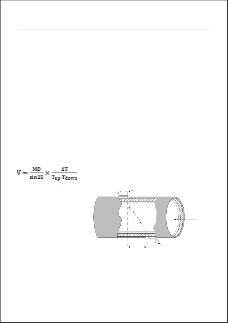
Where
0 is the include angle to the flow direction
M is the travel times of the ultrasonic beam
D is the pipe diameter
Spacing
Upstream transducer
ultrasonic igniting * built-in data-logger
§1.3 Principle of Measurement
The FDT-25 ultrasonic flow meter is designed to measure the fluid velocity of liquid within a closed
conduit. The transducers are a non-contacting, clamp-on type, which will provide benefits of nonfouling operation and easy installation.
The FDT-25 transit time flow meter utilizes two transducers that function as both ultrasonic
transmitters and receivers. The transducers are clamped on the outside of a closed pipe at a specific
distance from each other. The transducers can be mounted in V-method where the sound transverses
the pipe twice, or W-method where the sound transverses the pipe four times, or in Z-method where
the transducers are mounted on opposite sides of the pipe and the sound crosses the pipe once. This
selection of the mounting method depends on pipe and liquid characteristics. The flow meter operates
by alternately transmitting and receiving a frequency modulated burst of sound energy between the
two transducers and measuring the transit time that it takes for sound to travel between the two
transducers. The difference in the transit time measured is directly and exactly related to the velocity of
the liquid in the pipe, as shown in Figure 1.
Tup is the time for the beam from upstream transducer to the downstream one
Tdown is the time for the beam from downstream transducer to the upstream one
ΔT-Tup Tdown
Page 7
FDT-25 Handhold Ultrasonic Flowmeter 3
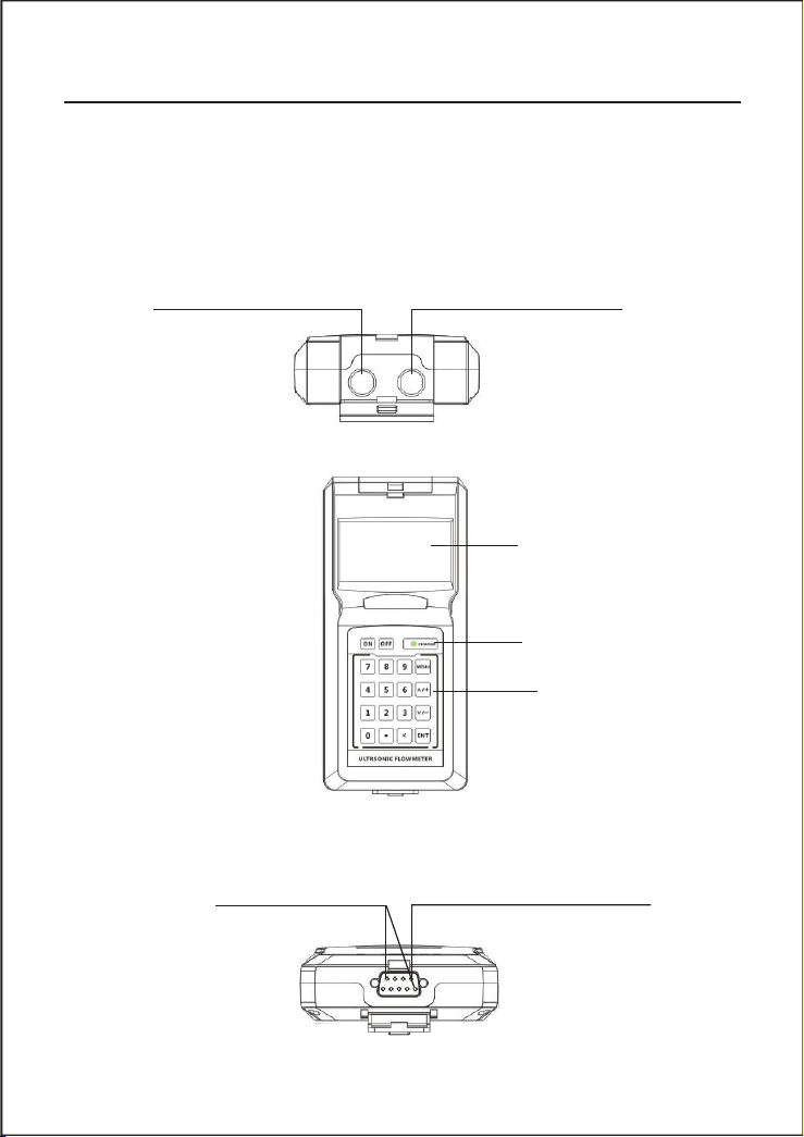
stream transduer socket
stream transduer socket
Front view
LCD DISPLAY
LED Charging Indicator
Keypad
§1.4 Parts Identification
Converter:
Top vierw
Bottom view
Pins for battery recharge
RS-232C communication interface
Page 8
4 FDT-25 Handhold Ultrasonic Flowmeter
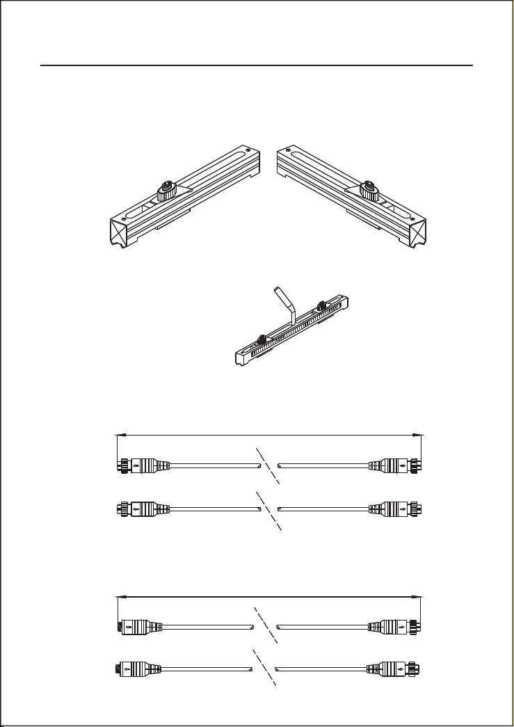
Red Terminal
5m
Red Terminal
Blue Terminal
Blue Terminal
Red Terminal
5m
Blue Terminal
Red Terminal
Blue Terminal
Transducers:
Standard-HM (50mm-700mm)
Standard-HS (20mm-100mm)
(Optional Accessaries)
Cable 5m x2
Extended Cable 5m x2(Optional Accessaries)
Page 9
FDT-25 Handhold Ultrasonic Flowmeter 5
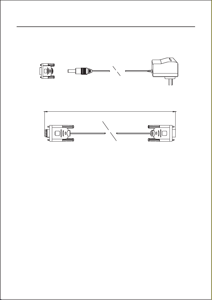
Converted Terminal and AC/DC Adapter
Cable of RS-232C interface
1m
§1.5 Typical Applications
The FDT-25 flow meter can be virtually applied to a wide range of measurements. The measured pipe
ranges 20-6000 mm [0.5 - 200 inch]. A variety of liquid applications can be accommodated: ultra-pure
liquids, potable water, chemicals, raw sewage, reclaimed water, cooling water, river water, plant effluent,
etc. Because the instrument and transducers are non-contacting and have no moving parts, the flow
meter can not be affected by system pressure, fouling or wear. Standard transducers are rated to 110 ℃.
Higher temperatures can be accommodated. For further information, please consult the manufacturer for
assistance.
§1.6 Data Integrity and Built-in Time-Keeper
All user-inputted configuration values are retained in the built-in non-volatile flash memory that
can store them for over 100 years, even if power is lost or turned off. Password protection is provided
to avoid inadvertent configuration changes or totalizer resets.
A time-keeper is integrated in the flow meter for the index of date totalizing and works as the time
base of flow accumulation. It keeps operating as long as the battery’s terminal voltage is over 1.5V.
In case of battery failure, the time-keeper will not keep running and it will lose proper time values.
The user must re-enter proper time values in case the battery becomes totally exhausted. An improper
time value affects no other functions but the date totalizer.
Page 10
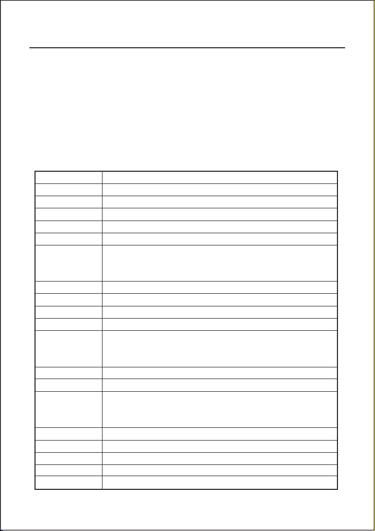
6 FDT-25 Handhold Ultrasonic Flowmeter
Linearity
0.5%
Repeatability
0.2%
Accuracy
±1% of reading at rates>0.2 mps
Response Time
0-999 seconds, user-configurable
Velocity
±32 m/s
Pipe Size
20mm-6000mm
Rate Units
Meter, Feet, Cubic Meter, Liter, Cubic Feet, USA Gallon, Imperial
Gallon, Oil Barrel, USA Liquid Barrel, Imperial Liquid Barrel, Million
USA Gallons. User configurable.
Totalizer
7-digit totals for net, positive and negative flow respectively
Liquid Types
Virtually all liquids
Security
Setup values Modification Lockout. Access code needs unlocking
Display
4x8 Chinese characters or 4x16 English letters
Communication
Interface
RS-232C, baud-rate: from 75 to 57600. Protocol made by the
manufacturer and compatible with that of the FUJI ultrasonic flow
meter. User protocols can be made on enquiry.
Transducers
Model M1 for standard, other 3 models for optional
TransducerCord Length
Standard 2x10 meters, optional 2x 500 meters
Power Supply
3 AAA Ni-H built-in batteries. When fully recharged it will last over
10 hours of operation.
100V-240VAC for the charger
Data Logger
Built-in data logger can store over 2000 lines of data
Manual Totalizer
7-digit press-key-to-go totalizer for calibration
Housing Material
ABS
Case Size
100x66x20mm
Handset Weight
514g (1.2 lbs) with batteries
§1.7 Product Identification
Each set of the FDT-25 Series flow meter has a unique product identification or ESN written into
the software that can only be modified with a special tool by the manufacturer. In case of any hardware
failure, please provide this number which is located on menu window number M61 when contacting
the manufacture.
§1.8 Specifications
Page 11

FDT-25 Handhold Ultrasonic Flowmeter 7
2. Starting Measurement
§2.1 Built-in Battery
The instrument can operate either from the built-in Ni-H rechargeable battery, which will last over
10 hours of continuous operation when fully recharged, or from an external AC/power supply
from the battery charger.
The battery charging circuits employ a scheme of constant-current and constant-voltage. It has a
characteristic of fast charging at the beginning and very slow charging when the battery approaches
to full recharge. Generally, when the green LED starts coming on, the battery would be nearly
95% recharged and when the red LED is off, the battery would be 98% recharged.
Since the charging current becomes tapered when the battery recharge is nearly completed, i.e.
the charging current becomes smaller and smaller, therefore, there should be no over-recharging
problem. That means the charging progress can last very long. The charger can be connected to
the handset all the time when an around-the-clock measurement is required.
When fully recharged, the terminal voltage reaches around 4.25V. The terminal voltage is displayed
on window M07. When the battery is nearly consumed, the battery voltage drops to below 3V.
The user can obtain an approximate battery working time from the battery voltage.
A software battery working time estimator is integrated in this instrument based on the terminal
voltage. Please note that the estimator may have relatively bigger errors in the estimated working
time, especially when the voltage is in the range of around 3.70 to -3.90 volt.
§2.2 Power On
Press the ON key to switch on the instrument and press the OFF to turn off the power.
Once the flow meter is switched on, it will run a self diagnostic program, checking first the hardware
and then the software integrity. If there is any abnormality, corresponding error messages will
display.
Generally, there should be no display of error messages, and the flow meter will go to the most
commonly used M enu Window Number 01 (short for M01) to display the Velocity, Flow Rate,
Positive Totalizer, Signal Strength and Signal Quality, based on the pipe parameters configured
last time by the user or by the initial program.
The flow measurement program always operates in the background of the user interface. This
means the flow measurement will keep on running regardless of any user menu window browsing
or viewing. Only when the user enters new pipe parameters will the flow meter change measurement
to the new parameter changes.
Page 12
8 FDT-25 Handhold Ultrasonic Flowmeter
When new pipe parameters have been entered or when the power has been just switched on, the
flow meter will enter an adjusting mode to make the signals magnified with proper amplification.
By this step, the flow meter is going to find the best threshold of receiving signal. The user will
see the progress by the number 1, 2, or 3, which are indicated on the right lower corner of the
LCD display.
When the transducers have been adjusted on the pipe by the user, the flow meter will re-adjust
the signal automatically.
Any user-entered configuration value will be retained into the NVRAM of the flow meter, until
it is modified by the user.
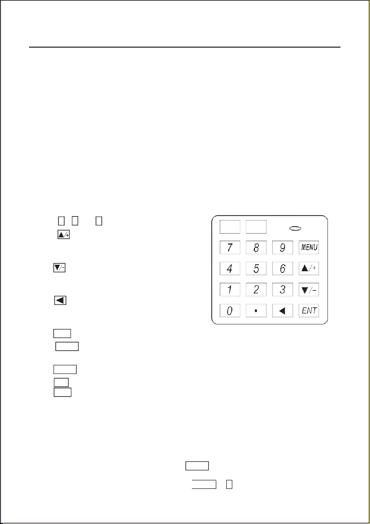
Keys 0
~
and•are keysto enter numbers
ON
OFF
Key is the going UP key, when the user
wants to go to the upper menu window. It also
works as + key when entering numbers
Key is the going DOWN key, when the user
wants to go down-sided menu window. It also
works as the
‘ ‘
key when entering numbers.
Key is backspace key, when the user wants
go left or wants backspace the left character that
is located to the left of the cursor.
Key ENT is the ENTER key for any inputting or selections.
CHARGE
The OFF key is for the power off.
The user interface of this flow meter comprises about 100 different menu windows that are
numberedbyM00,M01,M02.M99.
There are 2 methods to enter certain menu window:
(1) Direct going/entering. The user can press the MENU key followed by two-digit number keys.
For example, the menu window M11 is for the entering of pipe outer diameter. The display will
go to the M11 menu window after the user presses .
9
MENU
1
1
§2.3 Keypad
The keypad for the operation of the flow meter has 16+2 keys, as shown by the right dia
Key MENU is the key for the direct menu window jump over. Whenever the user wants to proceed
to a certain menu window, the user can press this key followed by 2-digit numbers.
The MENU key is shortened as the
The ON key is for the power on.
§2.4 Menu Windows
‘M’
key afterward when referring to the menu windows.
Page 13
4
FDT-25 Handhold Ultrasonic Flowmeter 9
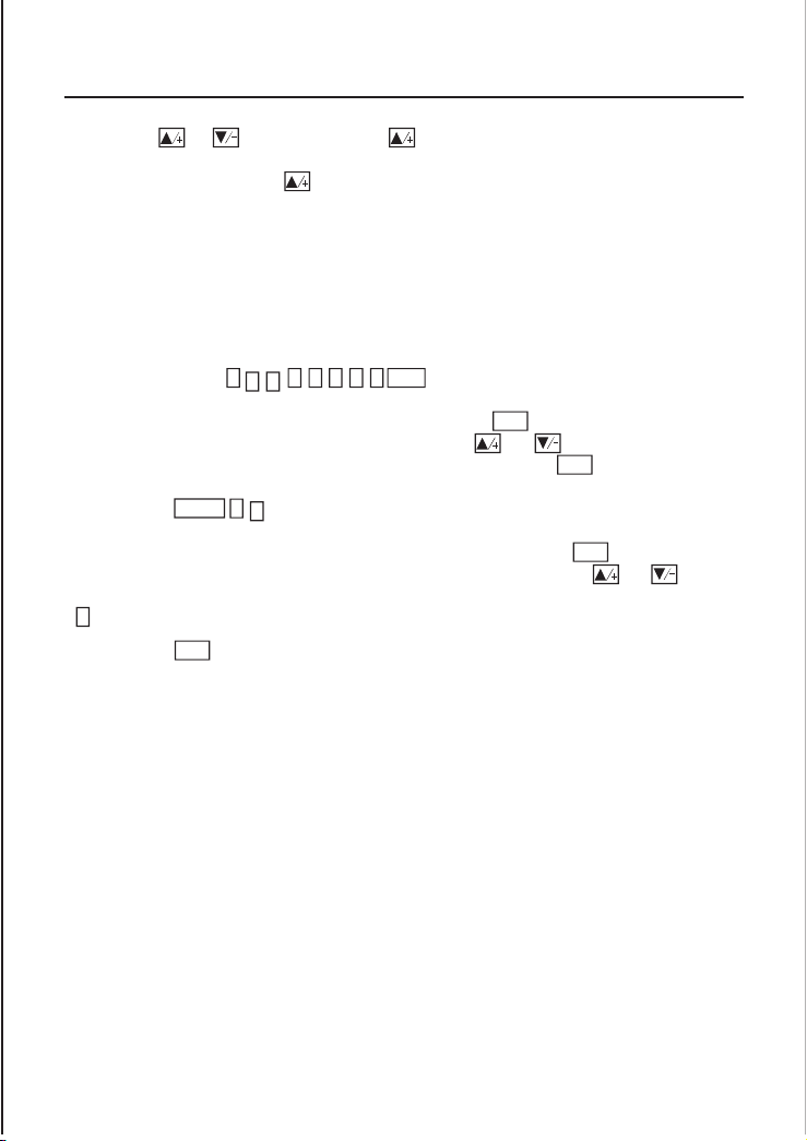
(2) Pressing and keys. Each time of the key pressing will proceed to the lower-numbered
(1) Menu windows for number entering, like M11 for the entering of pipe outer diameter.
(2) Menu windows for option selection/selecting options, like M14 for the selection of pipe materials.
(3) Displaying windows only, like M00 to display Velocity, Flow Rate etc.
following serial keys: 2
- 2 3 4 5 ENT .
selection, (the MENU 1
should be pressed first to enter this menu window if the current menu
19ENT
menu window. For example, if the current window is on M12, the display will go to the number
M11 window after pressing the key.
There are three different types of menu windows:
For number entering windows, the user can directly press the starting digit key when the user is
going to modify the value. F or example, when the current window is on M11, and the user is going
to enter 219.2345 as the pipe outer diameter, the user can get the numbers entered by pressing the
For the option selection windows, the user should first press the ENT key to a selection modification
mode and then select the relevant options by pressing the and keys or the digit keys to
select the option with a number antecedent to the option. In the end, the ENT key must be pressed
to make the selection. For example, with menu window M14 for the selection of pipe material
window is on a different window. The pipe material is stainless steel which has a number
antecedent to “stainless steel” on the display, the user should first press the ENT key to enter into a
selection modification mode, then either make the selection by pressing the and keys to
make the cursor on the line that displays
1 key directly.
Generally, the ENT key must be pressed to enter a modification mode. If the “Locked M47 Open’
message is indicated on the lowest line of the LCD display, it means the modification operations is
locked out. In such cases, the user should go to M 47 to have the instrument unlocked first before
any further modification can be made.
“1.
Stainless Steel”, or make the selection by pressing the
§2.5 Menu Windows Arrangement
M00~ M09 windows for the display of the flow rate, velocity, date time, tot alizers, battery voltage
and estimated working hours for the battery.
M10~M29windows for entering the pipe parameter.
M30~M38 windows for flow rate unit selections and totalizer unit selections.
M40~M49 windows for response time, zeroing, calibration and modification password setup.
M50~M53windowsforthe built-in logger
M60-M78 windows for time-keeper initialization, version and ESN information viewing and alarms.
M82 window for viewing date totalizer.
M90~M94are diagnostic windows for a more accurate measurement.
M97~ M99 are not windows but commands for the outputtingof displaycopying andpipe parameter setups.
M+0~M+8 are windows for some additional functions, including a scientific calculator, viewer on
records such as total working hours, turn-on and turn-off times, dates and times when the flow meter
has been turned on or turned off.
“1”
Page 14
ENT
10 FDT-25 Handhold Ultrasonic Flowmeter
(1) Pipe outer diameter
(2) Pipe wall thickness
(3) Pipe materials (for non-standard pipe materials*, the sound speed for the material must be
(4) Liner material and its sound speed and thickness, if there is any liner.
(5) Liquid type (for non-standard liquids, the sound speed of the liquid is also needed)
(6) Transducer type adapted to the flow meter. Generally the Standard M1 or the Frame M-sized
(7) Transducer mounting methods (the V-method or Z-method is the common option)
(8) Check up the Space displayed on M25 and install the transducers accordingly.
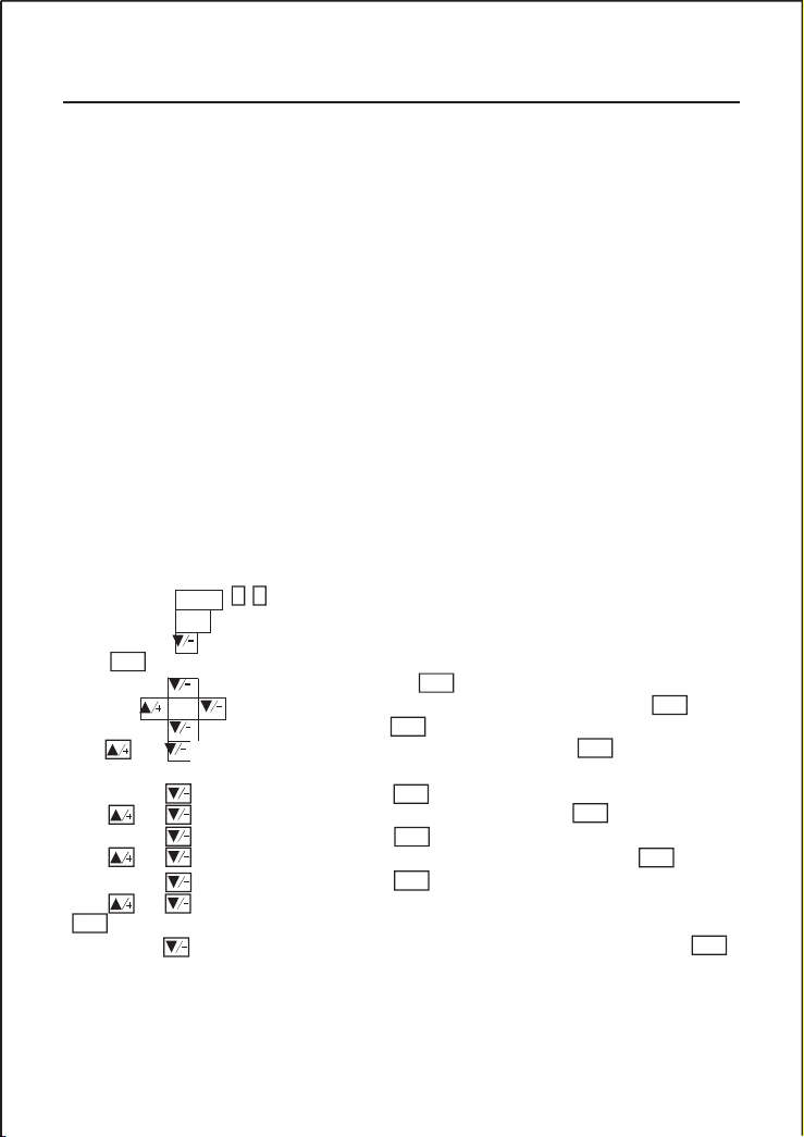
(1) Press keys
and then press
(2) Press key
press ENT key.
1 1 to enter M11 window to input the digits for the pipe outer diameter,
ey.
enter M12 window to input the digits for the pipe outer diameter and then
(3) Press key to enter M14 window, and press ENT key to enter the option selection mode.
Use keys
(4) Press key
keys and
to scroll up and down to the intended pipe material, and then press ENT key.
nter M16 window, press ENT key to enter the option selection mode, use
roll up and down to the liner material, and then press ENT key. Select “No
Liner”, if there is no liner.
(5) Press key to enter M20 window, press
key to enter the option selection mode, use
(6) Press key to enter M23 window, press
key to enter the option selection mode, use
(7) Press key to enter M24 window, press
key to enter the option selection mode, use
(8) Press key to enter M24 window to install the transducers on the pipe, and then press
ENT
ENT
ENTkto
and
to e
to sc
Other menu windows such as M88 have no functions, or functions were cancelled because they are
not applied to this version of the software.
§2.6 Steps to Configure the Parameters
The following parameters need to be configured for a proper measurement:
configured too)
*Standard pipe materials and standard liquids refer to those with the sound parameters that have
already been programmed into software of the flow meter, therefore there is no need to configure
them
transducers will be the selected option.
For standardpipe materials andstandardliquids, the following detailedstep-by-step setup is recommended.
keys and to scroll up and down to the proper liquid, and then press ENT key.
keys and to scroll up and down to the proper transducer type, and then press ENT key.
keys and to scroll up and down to the proper transducer mounting method, and then press
ENT key.
key to go to M01 for the results.
Page 15
FDT-25 Handhold Ultrasonic Flowmeter 11
(1) When the window display is between M 00 to M09, press a number key x , the user will go
(2) When the window display is under M 00 to M09, press the ENT key and the user will go to
Piping Configurat ion
and
Transducer Positio n
L up L dn
Upstream
Dimension
L up
x Diameters
Downstream
Dimension
L dn
x Diameters
10D 5D
L up L dn
L up L dn
L up
L dn
L up
L dn
L up
L dn
L up
L dn
10D 5D
10D 5D
12D 5D
20D 5D
20D 5D
30D 5D
The first-time users may need some time to get familiar with the operation. However, the user friendly
interface of the instrument makes the operation quite easy and simple. Before long, the user will
configure the instrument with very little key pressing, since the interface allows the user to go to
the desired operation directly without any extra steps.
The following tips will facilitate the operation of this instrument.
directly to the M0x window. For example, if the current window displays M01, press 7 and the user
will go to M07.
M90; press ENT key to return. Press the dot key to go to M11
When the window display is under M25, press ENT key to go to M01.
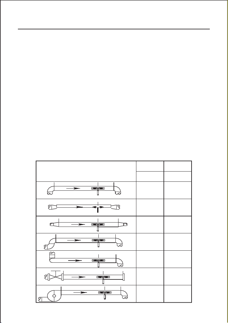
§2.7 Transducers Mounting Allocation
The first step in the installation process is the selection of an optimum location in order to obtain a
more accurate measurement. For this to be completed effectively, a basic knowledge about the piping
and its plumbing system would be advisable.
An optimum location would be defined as a straight pipe length full of liquid that is to be measured.
The piping can be in vertical or horizontal position. The following table shows
Page 16

12 FDT-25 Handhold Ultrasonic Flowmeter
(1) Install the transducers on a longer length of the straight pipe. The longer the better, and make
(2) Make sure that the temperature on the location does not exceed the range for the transducers.
(3) Take the pipe fouling into consideration. Select a straight length of a relatively newer pipe. If
(4) Some pipes have a kind of plastic liner, and between the outer pipe and the liner there may be a
(1) Locate an optimum position where the straight pipe length is sufficient, and where pipes are in
(2) Cleanany dust and rust. For a betterresult,polishing the pipewitha sander is stronglyrecommended.
(3) Apply adequate coupler to the spot where the transducers are to be installed and leave no gap
§2.8.1 Transducers Spacing
§2.8.2 V-method Installation
examples of optimum locations.
Principles to selection of an optimum location
sure that the pipe is completely full of liquid.
Generally speaking, the closer to the room temperature, the better.
the condition is not satisfying, consider the fouling thickness as part of the liner for a better result.
certain thickness difference that will prevent the ultrasonic waves from direct traveling. Such conditions
will make the measurement very difficult. Whenever possible, try to avoid this kind of pipes. If
impossible, try our plug-in transducers that are installed permanently on the pipe by drilling holes
on the pipe while liquid is running inside.
§2.8 Transducers Installation
The transducers used by the series ultrasonic flow meter are made of piezoelectric crystals both for
transmitting and receiving ultrasonic signals through the wall of liquid piping system. The
measurement is realized by measuring the traveling time difference of the ultrasonic signals. S ince
the difference is very small, the spacing and the alignment of the transducers are critical factors to
the accuracy of the measurement and the performance of the system. Meticulous care should be taken
for the installation of the transducers.
Steps to the inst allation of the transducers
a favorable condition, e.g., newer pipes with no rust and ease of operation.
between the pipe surface and the transducers.
Extra care should be taken to avoid any sand or dust particles left between the pipe outer surface
and the transducers.
To avoid gas bubbles inside the upper part of the pipe, the transducers should be installed horizontally
by the side of the pipe.
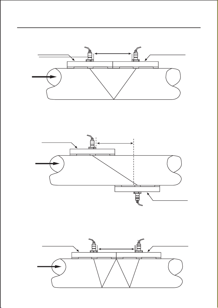
The spacing value shown on menu window M25 refers to the distance of inner spacing between
the two transducers. The actual transducers spacing should be as close as possible to the spacing
value.
V-method installation is the moswidely used mode for daily measurement with pipe inner diameters
ranging from 20 millimeter to 300 millimeter. It is also called reflective mode or method.
Page 17
FDT-25 Handhold Ultrasonic Flowmeter 13
Upstream transducer
Sensors Spacing
Downstream transducer
Upstream transducer
Sensors Spacing
Downstream transducer
Flow
TOP VIEW OF PIPE
§2.8.3 Z-method Installation
Z-method is commonlyused when the pipe diameter is between300 millimeters and 500 millimeters.
TOP VIEW OF PIPE
Upstream transducer
Flow
SensorsSpacing
Downstream transducer
§2.8.4 W-method Installation
W-method is usually used on plastic pipes with a diameter from 10 millimeters to 100 millimeters
TOP VIEW OF PIPE
Flow
Page 18

14 FDT-25 Handhold Ultrasonic Flowmeter
(1) Relocate a more favorable location, if the current location is not good enough for a stable and
(2) Try to polishthe outer surface of the pipe, and apply more coupler to increase the signal strength.
(3) Adjust the transducers both vertically and horizontally while checking the varying signal
(1) Interference of other instruments and devices such as a powerful transverter working nearby.
(2) Bad sonic coupling for the transducers with the pipe. Try to apply more coupler or clean the
(3) Pipes are difficult to be measured. Relocation is recommended.
§2.8.5 N-method Installation
Rarely used method.
§2.9 Installation Checkup
Through the checkup of the installation, one can: check the receiving signal strength, the signal
quality Q value, the traveling time difference of the signals, the estimated liquid speed, the measured
traveling time of the signals and the calculated traveling time ratio. Therefore, optimum measurement
result and longer running time of the instrument can be achieved.
§2.9.1 Signal Strength
Signal strength indicates the amplitude of receiving ultrasonic signals by a 3-digit number. [000]
means there is no signal detected, and [999] refers to the maximum signal strength that can be
received.
Although the instrument works well if the signal strength ranges from 500 to 999, stronger signal
strength should be pursued, because a stronger signal means a better result. The following methods
are recommended to obtain stronger signals:
reliable flow reading, or if the signal strength is lower than 700.
strength, stop at the highest position, and then check the transducers spacing to make sure the
transducers spacing is the same as what the M25 shows.
§2.9.2 Signal Quality
Signal quality is indicated as the Q value in the instrument. A higher Q value would mean a higher
Signal and Noise Ratio (short for SNR), and accordingly a higher degree of accuracy would be
achieved. Under normal pipe condition, the Q value is in the range 60-99, the higher the better.
Causes for a lower Q value could be:
Try to relocate the flow meter to a new place where the interference can be reduced.
surface, etc.
§2.9.3 Total Transit Time and Delta Time
The numbers displayed on menu window M93 are called total transit time and delta time respectively.
They are the primitive data for the instrument to calculate the flow rate inside the pipe. So the
flow rate indication will vary accordingly with the total time and delta time.
Page 19

FDT-25 Handhold Ultrasonic Flowmeter 15
(1) If the pipe parameters are correctly entered.
(2) If the actual spacing of the transducers is right and the same as what the window M 25 shows.
(3) If the transducers are installed properly in the right directions.
(4) If the mounting location is good and if the pipe has changed shape or if there is too much
(5) Other poor conditions.
The total transit time should remain stable or vary little.
If the delta time fluctuates higher than 20%, it means there are certain kinds of problems with
the transducer installation.
§2.9.4TimeRatiobetweentheMeasuredTotal Transit Time and the Calculated Time
This ratio would be used to check the transducer installation. If the pipe parameters are entered
correctly and the transducers are installed properly, the value for this ratio should be in the range
of 1003. If this range is exceeded, the user should check:
fouling inside the pipes
Page 20

16 FDT-25 Handhold Ultrasonic Flowmeter
3. How To
When
‘R’
is displayed inthelowest right corner of LCDdisplay,theinstrument is workingproperly,
generally speaking.
If an
‘H’
flashes on that place, there could be poor signal received. Please refer to the chapters
on diagnosis.
If a
‘J’
is displayed, it means that the hardware of this instrument could be out of order. Refer to
the chapter on diagnosis.
(1) Make sure that the instrument works properly
(2) Check the flow rate for the indication. If the displayed value is POSIT IVE, the direction of
the flow will be from the RED transducers to the BLUE transducers; if the displayed value is
NEGATIVE, the direction will be from the BLUE transducers to the RED transducers;
Use window M33 to select a proper totalizer. M ake sure that the totalizer pulse is appropriately
speeded. It should not be too fast and neither too slow. A speed of producing a pulse in several
seconds or minutes is preferable.
If the totalizer multiplier is too small, there can be a loss of accumulation pulse because the output
device can output only one pulse in a measurement period (500milliseconds)
If the totalizer multiplier is too large, the output pulse will be too fewer for the devices that are
connected with the instrument for a quicker response.
§3.1 How to judge if the instrument works properly
If an
‘I’
is displayed, it means that there is no signal detected.
§3.2 How to judge the liquid flowing direction
§3.3 How to change between units systems
Use menu window M30 for the selection of unit system in English or Metric system.
§3.4 How to select a required flow rate unit
Use menu window M31 to select the flow unit first and then the timing unit.
§3.5 How to use the totalizer multiplier
§3.6 How to open or shut the totalizers
Use M34, M 35 and M36 to turn on or turn off the POS, NEG, or NET totalizer respectively.
§3.7 How to reset the totalizers
Use M37 to reset the proper totalizer.
Page 21

FDT-25 Handhold Ultrasonic Flowmeter 17
Use M37, when the ‘selection’ message is displayed. Press the dot key first and the message ‘Master
Erase’ will display,thenpressthebackspace key
The master erase step will erase all the parameters entered by the user and setup the instrument with
default values.
The damper acts as a filter for a stable reading. If
‘0’
is entered in window M 40, that means there
is no damping. A bigger number brings a more stable effect. But bigger damper numbers will prevent
the instrument from acting quickly.
The number displayed in window M41 is called the low-cutoff value. The flow meter will replace
these flow rate values that are absolutely less than the low-cutoff value with
‘0’.
This means the flow
meter will avoid any invalid accumulation when the actual flow is below the zero-cutoff value.
The low-cutoff value does not affect the flow measurement when the actual flow is absolutely greater
than the low-cutoff value.
There exists a ‘Zero Point’ with certain installation which means the flow meter will display a non-
zero value when the flow is absolutely stopped. In this case, setting a zero point with the function
in window M42 will bring a more accurate measurement result.
Make sure that the flow is absolutely stopped, then run the function in window M 42 by pressing
the ENT key.
A scale factor is the ratio between the ‘actual flow rate’ and the indicated value by the flow meter.
The scale factor can be determined by calibration with flow calibration equipment.
The system locker provides a means of preventing inadvertent configuration changes or totalizer
resets.
When the system is locked, menu window browsing can be done without affecting any change, but
any modifications are prohibited.
The system can be locked without a password or with a one 1 to 4 digit password. With a no-password
locking, directly press the ENT key when the password input prompt displays.
§3.8 How to restore the flow meter with default setups
§3.9 How to use the damper
Numbers 0 to 10 are commonly used for the damper value.
§3.10 How to use the zero-cutoff function
§3.11 How to setup a zero point
§3.12 How to get a scale factor for calibration
§3.13 How to use the operation locker
If the password is forgotten, please contact the factory.
Page 22

18 FDT-25 Handhold Ultrasonic Flowmeter
§3.14 How to use the built-in data logger
The data logger has a space of 24K bytes of memory, which will hold about 2000 lines of data.
Use M50 to turn on the logger and for the selection for the items that is going to be logged.
Use M51 for the times when the logging begins and at how long an interval sustains and how long
the data logging will last.
Use M52 for the direction of logging data. The default setting will permit the logging data to be
stored in the logger buffer.
Logging data can be redirected to the RS-232C interface without being stored into the logger buffer.
Use M53 to view the data in the logger buffer.
Dumping the logging data through the RS-232C interface and the clearing of the buffer can be
operated with a function in window M52.
§3.15 How to use the Frequency Output
There is a Frequency Output in all series flow meters. This frequency output signal, which
represents the flow rate, is intended to connect with other instruments.
The Frequency Output is totally user-configurable. Generally, four parameters should be configured
for the setups.
Enter the lower flow rate value in window M68 and the higher flow rate value in window M69.
Enter the frequency range in window M67.
For example, assume that the flow rate varies in a range 0m3/h to 3000m3/h, and an output signal
is at a maximum frequency of 1000Hz, the minimum of 200Hz is going to be required for other
instrumentation. The user should enter 0 in M68 and 3000 in M69, and enter 200 and 1000 in window
M67.
Please note that the user has to make the selection with OCT setups in window M78 by selecting
the 13thoption reading like ‘FO output’ to direct the frequency output to the OCT OUTPUT hardware
device.
§3.16 How to use the Totalizer Pulse Output
The totalizer output will produce a pulse output with every unit flow of the totalizer.
Refer §3.4 and §3.5 for the setups of the totalizer units and multiplier.
The totalizer pulse output can only be realized by mapping the pulse output to the OCT or BUZZER
hardware devices.
For example, assume that the POS totalizer pulse output is needed, and every pulse should represent
0.1cubic meter of liquid flow; the pulse output will be mapped to the internal Buzzer, so that with
every 0.1 cubic meter of flow the BUZZER will beep for a while.
Page 23

FDT-25 Handhold Ultrasonic Flowmeter 19
(1) Select the unit Cubic Meter under window M32.
(2)
Select the Multiplier as ‘2. X0.1’ under window M33.
(3)
Select the output option ‘9. POS INT Pulse’ under window M77. (INT stands for totalized )
(1) Alarms on when there is no receiving signal
(2) Alarms on when there is poor signal received.
(3) Alarms on when the flow meter is not in normal measurement modes.
(4) Alarms on reverse flow.
(5) Alarms on the overflow of the Frequency Output
(6) Alarms on when the flow is out of a designated range set by the user.
(1) Enter 300 under M73 for #1 alarm low flow rate
(2) Enter 2000 under M 74 for #1 alarm high flow rate
(3)
Select the item reading like
‘6.
Alarm
#1’
under M77.
The following setups should be taken/performed:
§3.17 How to produce an alarm signal
There are 2 types of hardware alarm signals that are available with this instrument. One is the Buzzer,
and the other is the OCT output.
Both for the Buzzer and OCT output the triggering sources of the event include the following:
There are two out-of-normal-range alarms in this instrument. They are called #1 Alarm and #2 Alarm.
The flow range can be user-configurable through M73, M74, M 75, M76.
For example, assume that the Buzzer should start beeping when the flow rate is less than 300 m3/h
and greater than 2000m3/h, the following steps for setups would be recommended.
§3.18 How to use the built-in Buzzer
The built-in buzzer is user-configurable. It can be used as an alarm. Use M77 for setups.
§3.19 How to use the OCT output
The OCT output is user-configurable, which can be performed by selecting the proper input source
such as pulse output.
Use M78 for the setups.
Please make sure that the Frequency Output shares the OCT.
The OCT output shares pins with the RS-232C interface, and the terminal is at Pin 6 and the ground
is at Pin 6.
§3.20 How to modify the built-in calendar
No modification on the built-in calendar will be needed in most cases. The calendar runs on insignificant
amount of power supply. Modification will be required only in such cases as when the battery is
totally consumed, or when the changing of the battery takes a long time.
Page 24

20 FDT-25 Handhold Ultrasonic Flowmeter
Press the ENT key under M61 for Modification. Use the dot key to skip over these digits that need
no modification.
§3.21 How to adjust the LCD contrast
Use M70 to the LCD contrast. The adjusted result will be storedin the EEPROM so that the MASTER
ERASE will make no effect on the contrast.
§3.22 How to use the RS232 serial interface
Use M62 for the setup of the RS-232C serial interface.
§3.23 How to view the Date Totalizers
Use M82 to view the date totalizers that are comprised of a daily totalizer, a monthly totalizer and
a yearly totalizer.
§3.24 How to use the Working Timer
Use the working timer to check the time that has passed with a certain kind of operation. For example,
use it as a timer to show how long a fully-charged battery will last.
Under M 72, press ENT key and then select YES to reset the timer.
§3.25 How to use the manual totalizer
Use M28 for the manual totalizer. Press ENT key to start and stop the totalizer.
§3.26 How to check the ESN and other minor details
Every set of the series flow meter utilizes a unique ESN to identify the meter. The ESN is an 8digit number that provides the information of version and manufacturing date.
The user can also employ the ESN for instrumentation management.
The ESN is displayed in window M61.
Other details about the instrument are the total working hours displayed in window M+1, and the
total power-on times displayed in window M +4.
§3.27 How to know how long the battery will last
Use M07 to check how long the battery will last. Also please refer to §.2.1
§3.28 How to charge the built-in battery
Refer to §2.1
Page 25
FDT-25 Handhold Ultrasonic Flowmeter 21
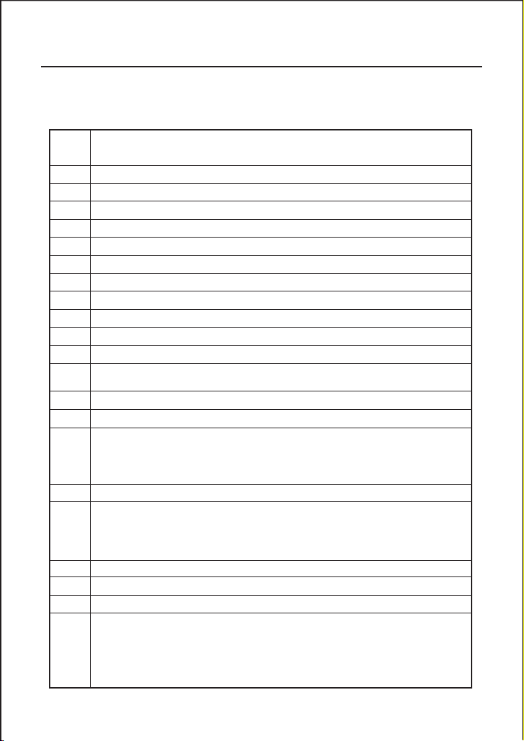
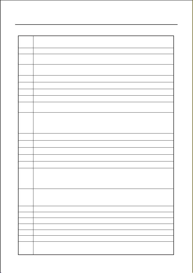
4. Menu Window Details
Men
u
w
ind
ow
No.
Function
M00
Display three positive negative net totalizers, signal strength, signal quality and working status
M01
Display POS totalizer, flow rate, velocity, signal strength, signal quality and working status
M02
Display NEG totalizer, flow rate, velocity, signal strength, signal quality and working status
M03
Display NET totalizer, flow rate, velocity, signal strength, signal quality and working status
M04
Display date and time, flow rate, signal strength, signal quality and working status
M05
Display date and time, velocity, signal strength, signal quality and working status
M06
Display the wave shape of the receiving signal
M07
Display the battery terminal voltage and its estimated lasting time
M08
Display the all the detailed working status, signal strength, signal quality
M09
Display today’s total flow, velocity, signal strength, signal quality and working status
M10
Window for entering the outer perimeter of the pipe
M11
Window for entering the outer diameter of the pipe
0 to 6000mm is the allowed range of the value.
M12
Window for entering pipe wall thickness
M13
Window for entering the inner diameter of the pipe
M14
Window for selecting pipe material
Standard pipe materials (that the user need not know the speed ) include:
(0) carbon steel (1) stainless steel (2) cast iron (3) ductile iron (4) copper
(5) PVC (6) aluminum (7) asbestos (8) fiberglass
M15
Window for entering the pipe material speed only for non-standard pipe materials
M16
Window for selecting the liner material, select none for pipes without any liner
Standard liner materials that the user need not know the speed include:
(1) Tar Epoxy (2) Rubber (3) Mortar (4) Polypropylene (5) Polystryol
(6)Polystyrene (7) Polyester (8) Polyethylene (9) Ebonite (10) Teflon
M17
Window for entering the liner material speed only for non-standard liner materials
M18
Window for entering the liner thickness, if there is a liner
M19
Window for entering the ABS thickness of the inside wall of the pipe
M20
Window for selecting fluid type
For standard liquids that the user need not know the liquid speed include:
(0) Water (1) Sea Water (2) Kerosene (3) Gasoline (4) Fuel oil (5) Crude Oil
(6) Propane at -45C (7) Butane at 0C (8)Other liquids (9) Diesel Oil (10)Caster Oil
(11)Peanut Oil (12) #90 Gasoline (13) #93 Gasoline (14) Alcohol (15) Hot water at 125C
Page 26
22
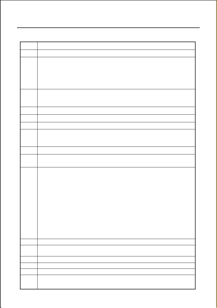
M21
Window for entering the fluid sonic velocity only for non-standard liquids
M22
Window for entering the viscosity of the non-standard liquids
M23
Window for selecting the proper transducers
There are 14 different types of transducers for selection.
If the user-type-transducers are used, 4 user type wedge parameters, which will be
prompted by the software, should be entered following.
If theπtype transducersareused,3π
type transducersand pipeparameters should be
entered following.
M24
Window for selecting the transducer mounting methods
Four methods can be selected:
(0) V-method (1) Z-method (2) N-method (3) W-method
M25
Display the transducer mounting spacing
M26
Entry to store the parameter configuration into the internal NVRAM
M27
Entry to load one set of saved parameters
M28
Select YES or NO for the instrument to determine whether or not to hold (or to keep)
the last correct value when poor signal condition occurs. YES is the default setup
M29
Enter a value ranging from 000 to 999. 0 is the default value
M30
Window for selectingunit system. Default value is
‘Metric’.
The change from English
to Metric or vice versa will not affect the unit for totalizers.
M31
Window for selecting flow rate that will be used by the instrument afterward.
Flow rate can be in
1. Cubic meter short for (m3)
2. Liter (l)
3. US A gallon (gal)
4. Imperial Gallon (igl)
5. Million USA gallon (mgl)
6. Cubic feet (cf)
7. US A liquid barrel (bal)
8. Imperial liquid barrel (ib)
9. Oil barrel (ob)
The flow unit in terms of time can be per day, per hour, per minute or per second. So
there are 36 different flow rate units in total for selection.
M32
Window for selecting the totaliziers’ working unit
M33
Select totalizer multiplier
The multiplier ranges from 0.001 to 10000
M34
Turn on or turn off the NET totalizer
M35
Turn on or turn off the POS totalizer
M36
Turn on or turn off the NEG totalizer
M37
(1) Totalizer reset
(2) Restore the instrument to the default parameters as the manufacturer did
FDT-25
Handhold Ultrasonic Flowmeter
Page 27
FDT-25 Handhold Ultrasonic Flowmeter 23
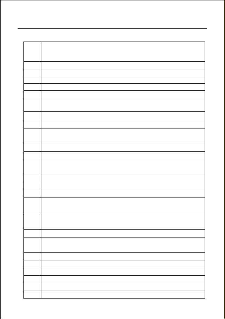
by pressing the dot key followed by the backspace key. Take care or make note on the
parameters before doing the restoration
M38
Press-a-key-to-run or to stop totalizer for easier calibration
M39
Operational interface language selection in Chinese and English. This selection makes
it possible that more than 2 billions of people on the world can read the menu.
M40
Flow rate damper for a stable value. The input range is 0 to 999 seconds.
0 means there is no damping. Default value is 10 seconds
M41
Lower flow rate cut-off to avoid invalid accumulation.
M42
Zero point setup under the condition when there is no liquid running inside the pipe.
M43
Clear the zero point set by the user, and restore the zero point set by the manufacturer
M44
Set up a manual flow bias. Generally this value should be 0.
M45
Scale factor for the instrument. The default value is
‘1’.
Keep this value as
‘1’,
when no user calibration has been made.
M46
Network environment Identification Number. Any integer can be entered except 13(0DH,
carriage return), 10 (0AH, line feeding), 42 (2AH), 38, 65535.
Every set of the instrument in a network environment should have a unique IDN. Please
refer to the chapter for communication.
M47
System locker to avoid modification of the parameters
M48
Not used
M49
Communication tester
M50
“Option” selection for the built-in logger. It also functions as the switch of logger
M51
Time setup for the data logger
M52
(1)
Data logging direction control. If ‘To RS-232’ is selected, all the data produced by
the data logger will be transmitted out through the RS-232 interface
(2)
If ‘To buffer ‘ is selected, the data will be stored into the built-in logger memory
(3) Buffer transferring and buffer clearing
M53
Logger buffer viewer. It functions as a file editor. Use Dot, backspace UP and DN keys
to browse the buffer.
If the logger is ON, the viewer will automatically refresh once new data are stored
M54
Not used
M55
Nod used
M56
Not used
M57
Not used
M58
Not used
M59
Not used
M60
99-year calendar. Press ENT for modification. Use the dot key to skip the digits that
need no adjusting.
Page 28
24 FDT-25 Handhold Ultrasonic Flowmeter
M61
Display Version information and Electronic S erial Number (ESN) that are unique for
each series flow meter.
The users can employ the ESN for instrumentation management
M62
RS-232 setup. Baud rate can be 75 to 115200 bps
M63
Not used
M64
Not used
M65
Not used
M66
Not used
M67
Input the frequency range for the frequency output. The biggest range is 0Hz-9999Hz.
Default value is 1-1001 Hz
M68
Enter a flow rate value that corresponds to lower frequency
M69
Enter a flow Rate value that corresponds to higher frequency
M70
LCD display backli ght control. The entered value indicates how many seconds the
backlight will be on with every key pressing.
M71
LCD contrast control. The LCD will become darker when a small value is entered.
M72
Working timer. It can be cleared by pressing ENT key, and then select YES.
M73
Enter Lower Flow Rate value that will trigger the #1 Alarm. There are two virtual alarms
in the system. By
“virtual”
we mean that the user must redirect the output of the alarms
by setuping the output hardware in M78 and M77
M74
Enter the higher flow rate value that will trigger the #1 Alarm.
M75
Enter the lower flow rate value that will trigger the #2 Alarm.
M76
Enter the higher flow rate value that will trigger the #2 Alarm.
M77
Buzzer setup.
If a proper input source is selected, the buzzer will beep when the trigger event occurs
M78
OCT (Open Collect Transistor Output) setup
By selecting a proper input source, the OCT hardware will close when the trigger event
occurs
M79
Not used
M80
Work as a keypad and display for another Handheld set by RS-232 connected with the
handset
M81
Not used
M82
Date totalizer
M83
Not used
M84
Not used
M85
Not used
M86
Not used
Page 29
FDT-25
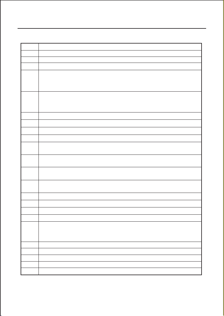
M87
Not used
M88
Not used
M89
Not used
M90
Display signal strength, signal quality, time ratio on the upper right corner.
M91
Displays the Time Ratio between the Measured Total Transit Time and the Calculated
time. If the pipe parameters are entered correctly and the transducers are properly installed,
the ratio value should be in the range of 100±3%. Otherwise the entered parameters
and the transducer installation should be checked.
M92
Displays the estimated fluid sound velocity. If this value has an obvious difference with
the actual fluid sound speed, pipe parameters entered and the transducer installation
should be checked again.
M93
Displays total transit time and delta time(transit time difference)
M94
Displays the Reynolds number and the pipe factor used by the flow rate program.
M95
Not used
M96
Not used
M97
Command to record the pipe parameters entered by the user either to the built-in data
logger or to RS-232C serial interface
M98
Command to record the diagnostic information either to the built-in data logger or to
RS-232C serial interface
M99
Command to copy the current display either to the built-in data logger or to RS-232C
serial interface
M+0
Browse the 64 recorded instrument power-on and power-off date and time with the flow
rate at the time of power on and off
M+1
Displays the total working time of the instrument
M+2
Displays the last power-off date and time
M+3
Displays the last power-off flow rate
M+4
Displays the times of instrument powered on(the instrument has been powered on)
M+5
A scientific calculator for the convenience of field working.
All the values are in single accuracy.
The drawback is that the user can’t operate it by direct key-pressing
M+6
Not used
M+7
Not used
M+8
Not used
M+9
Not used
M-0
Entry to hardware adjusting windows only for the manufacturer
Handhold Ultrasonic Flowmeter
25
Page 30
26
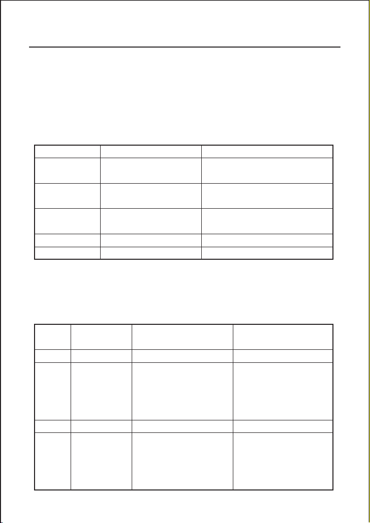
Error message
causes
Counter-measures
ROM Testing Error
Segment Test Error
Problem with the software
(1)Power on again
(2)Contact with factory
Stored Data Error
The parameters entered by
the user lose integration.
When this message displays, the user should
press ENT key, and all the configuration
will be restored to the default state.
Timer Slow Error
Timer Fast Error
Problem with the timer-keeper
or the crystal oscillator.
(1)Power on again
(2)Contact with factory
Date Time Error
Number errors with the calendar
Initializethecalendar by menu window M61
Reboot repetitively
Hardware problems
Contact the factory
Error code
Correspondent
Message displayed
on M 08
Causes
Counter-measures
R
System Normal
No error
!
Detect No Signal
(1)
No Signals detected
(2)
Transducers installed improperly
(3)Toomuch fouling
(4)Pipe linersaretoothick.
(5)Transducer cords are not properly
connected
(1)Relocate measuring location
(2)Clean the spot
(3)Check the cords
J
Hardware Error
Hardware problem
Contact the factory
H
PoorSig Detected
(1)Poor signal detected
(2) T ransducer s ins t al led
improperly
(3)Too much fouling
(4)The pipe liners are too thick.
(5)Problemwithtransducers cords
(1)Relocate measuring place
(2)Clean the spot
(3)Check the cords
(4)Check the coupler
FDT-25
Handhold Ultrasonic Flowmeter
5.Troubleshooting
§5.1 Power-on Error Displays and Counter-Measures
The series ultrasonic flow meter provides an automatic power-on diagnosis for the
hardware problems. When any message (with the power on) in the following table displays, countermeasures should be taken.
§5.2 Error Code and Counter-Measures
The series ultrasonic flow meter will show Error Code in the lower right corner with a single
letter like I, R etc. on menu windows M00, M01, M02, M03, M90 and M08. When any
abnormal Error Code shows, counter-measures should be taken.
Page 31

FDT-25 Handhold Ultrasonic Flowmeter 27
Q
Frequ OutputOver
The actual frequency for the
Frequency Output is out of the
range set by the user
Check the value entered at M66,
M67,M68 and M69, and try to
enter a larger value on M69
F
System RAM Error
Date Time Error
CPU or IRQ Error
ROM Parity Error
(1) Temporary problems with
RAM, RTC
(2) Permanent problems with
hardware
(1) power on again
(2) contact factory
2
3
Adjusting Gain
Instrument is in the progress of
adjusting the gain for the signal,
and the number indicates the
progressive steps
K
Empty pipe
(1) No liquid inside pipe
(2) Setup error on M29
(1) Relocate where the pipe is
full of liquid
(2) Enter 0 on M29
(1) When the actual flow inside the pipe is not standstill, but the instrument displays 0.0000 for
(2) The displayed flow rate is much lower or much higher than the actual flow rate in the pipe
(a)
There is probably an offset value wrongly entered by the user in M44. Enter
‘0’
in M44.
(b) Problem with transducer installation.
(c)
There is a ‘Zero Point’.Try to
‘zero’
the instrument byusing M42 and make surethat the flow
(3) The battery can not work as long as the time period as indicated by M07
(a) Battery should be replaced due to the end of the service life.
(b) Newly changed battery does not fit the battery estimating software. Customizing the battery
§5.3 Other Problems and Solutions
the flow rate, and
value?
The problems are likely caused by the user who has used the ‘Set Zero’ function on this non-
standstill flowing pipe. To solve this problem, use the ‘Reset Zero’ function on menu window
M43.
under normal working conditions.
inside the pipe should be standstill.
with the software should be taken. Please contact the factory.
‘R’
displaying signal strength and the signal quality Q (value) has a satisfactory
Page 32

28 FDT-25 Handhold Ultrasonic Flowmeter
(c) The battery has not been fully recharged or the recharge has been stopped too many times
(d) There is indeed a time difference between the actual working time and the estimated one,
halfway.
especially when the terminal voltage is in the range 3.70 and 3.90 volt. Please refer to battery
voltage for a closer estimated working time.
Page 33
FDT-25 Handhold Ultrasonic Flowmeter 29
6. Communication Protocol
Pin1for battery recharge, positive input
2
RXD3TXD4not used
5
GND6OCT output
7
not used
8
for battery recharge, negative input
9
RING input for connecting a MODEM
Command
Function
Data Format
DQD(CR)
Return flow rate per day
±d.ddddddE±dd(CR)(LF)*
DQH(CR)
Return flow rate per hour
±d.ddddddE±dd(CR)(LF)
DQM(CR)
Return flow rate per minute
±d.ddddddE±dd(CR)(LF)
DQS(CR)
Return flow rate per second
±d.ddddddE±dd(CR)(LF)
DV(CR)
Return flow velocity
±d.ddddddE±dd(CR)(LF)
DI+(CR)
Return POS totalizer
±dddddddE±d(CR)(LF )**
DI-(CR)
Return NEG totalizer
±dddddddE±d(CR)(LF)
DIN(CR)
Return NET totalizer
±dddddddE±d(CR)(LF)
DID(CR)
Return Identification Number
ddddd (CR) (LF)
DL(CR)
Return signal strength and quality
S-ddd,ddd Q-dd(CR) (LF)
DT(CR)
Return date and time
yy-mm-dd hh:mm:ss(CR) (LF)
M@(CR)***
Send a key value as if a key is pressed
LCD(CR)
Return the current window display
§6. 0 General
The series ultrasonic flow meter integrates a standard RS-232C communication interface and a
complete set of communication protocols that are compatiblewith that of the Fuji’s ultrasonic flow
meter.
§6.1 Interface Pin-out Definition
§6.2 the Protocol
The protocol is comprised of a set of basic commands that is a string in ASCII format, ending with
a carriage (CR) and line feed (LF). Commonly used commands are listed in the following table.
Page 34
30 FDT-25 Handhold Ultrasonic Flowmeter
FOdddd(CR)
Force theFOoutput witha frequencyinddddHz
ESN(CR)
Return the ESN for the instrument
Dddddddd(CR)(LF)
RING(CR)
Handshaking Request by a MODEM
OK(CR)
Response from a MODEM
No action
GA
Command for GSM messaging
Please contact factory for detail
GB
Command for GSM messaging
GC
Command for GSM messaging
DUMP(CR)
Return the buffer content
In ASCII string format
DUMP0(CR)
Clear the whole buffer
In ASCII string format
DUMP1(CR)
Return the whole buffer content
InASCIIstringFormat, 24KB inlength
W
Prefix before an Identification Number in
a network environment. The IDN is a word,
ranging 0-65534.
N
Prefix before an Identification Number in
a network environment. The IDN is a single
byte value, ranging 00-255.
P
Prefix before any command
&
Command connector to mak e a longer
command by combining up to 6 commands
(1) Prefix P
Notes * CR stands for Carriage Return and LF for Line Feed.
**
*** @ stands for the key value, e.g., 30H for the
§6.3 Protocol Prefix Usage
The prefix P can be added before any command in the above table to have the returning data
followed with two bytes of CRC check sum, which is the adding sum of the original character
string.
Take the DI+(CR) command as an example. Assume that DI+(CR) would return +1234567E+0m3
(CR)(LF)( the string in hexadecimal is 2BH, 31H, 32H, 33H, 34H, 35H, 36H, 37H, 45H, 2BH,
30H, 6DH, 33H, 20H, 0DH, 0AH) , then PDI(CR) would return +1234567E+0m3!F7(CR)(LF).
‘!’
acts as the starter of check sum which is yielded by adding up the string 2BH, 31H, 32H, 33H,
34H, 35H, 36H, 37H, 45H, 2BH, 30H, 6DH, 33H, 20H.
Please note that there will be SPACES (20H) before
‘d’
standsfor the0~9 digitnumbers.
‘!’ .
‘0’
key.
Page 35
FDT-25 Handhold Ultrasonic Flowmeter 31
(2) Prefix W
(3) Prefix N
(4) Command Connector &
Key
Hexadecimal
Key code
Decimal
Key code
ASCII
Code
0
30H480131H491232H502
3
33H513434H524535H535636H546
7
37H557
Key
Hexadecimal
Key code
Decimal
Key code
ASCII
Code
8
38H568939H579-3AH58:
▲
3BH,0BH
59
;
3CH,0CH
60
<
3DH,0DH
61
-
3EH62>
3FH63?
The prefix W should be used in the network environment. The usage format is W + digit string
which stands for the IDN + basic command.
The digit string should have a value between 0 and 65534 except 13(0DH), 10 (0AH), 42(2AH,*),
38(26H, &).
For example,if the IDN-12345 instrument is addressed andreturningthevelocity of that
instrument is requested, the command will be W12345DV(CR).
The prefix N is a single byte IDN network prefix, not recommended in a new design. It is
reserved only for the purpose of the compatibility with the former versions
The & command connector can connect up to 6 basic commands to form a longer command so
that it will make the programming much easier.
For example, assume that the measurement of an instrument with IDN-4321 are going to be
returned, and (then) all the following 3 values--- (1) flow rate (2) velocity (3)POS totalizer---will
be returned simultaneously. The combined command would be W4321DQD&DV&DI+(CR),
and the result would be:
+1.234567E+12m3/d(CR)
+3.1235926E+00m/s(CR)
+1234567E+0m3(CR)
§6.4 Codes for the Keypad
The codes for the keypad should be used when the instrument is connected with other terminals
that operate the instrument bytransmittingthe
function, remote operation of this instrument can be reali zed, even via the Internet.
‘M’
commandalong with the keypad code.Bythis
 Loading...