

Page 1
NEWPORT
OMEGA
omega.co.uk
EWSE Series
Rugged, Weatherproof Temperature Sensors and Transmitters
INSTRUCTION
MUK001/0311
SH EET
Shop online at: omega.co.uk e-mail: [email protected]
For latest product manuals: omega.co.uk
1.0 Description
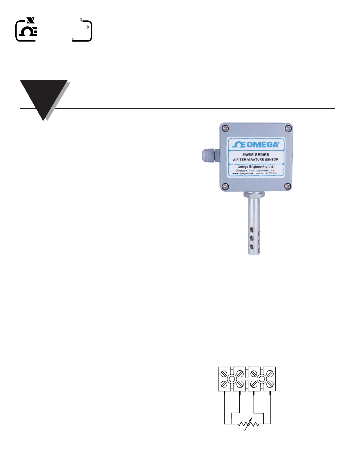
The EWSE air temperature sensors are designed for wall or pipe
mounting in harsh indoor or outdoor environments.
A rugged 6mm diameter sheathed RTD probe is housed in the centre
of a 14mm dia. outer protection tube. The RTD sensor terminal block or
optional transitter are housed in a tough aluminium alloy enclosure,
rated to IP65.
An IP68 cable gland is fitted to the left hand side of the enclosure,
suitable for cables from 2.5 to 6.5mm diameter.
2.0 Receiving and Unpacking
Please inspect the packaging and sensor thoroughly for any signs of
transit damage. Please notify Omega customer service if any damage
is found.
3.0 Specifications
Dimensions:
Box: 80 W x75 H x 58 mm D
Sensors: 75 mm long x 14 mm O.D
Cable Entry: IP68 gland for 2.5 to 6.5 O.D cable
EWSE-Pt100 Sensor Only Model:
Sensor Type:
- Pt100 class A 4-wire standard
- Pt1000 on request
Ambient Temperature Range:
-50 to +100°C
Electrical Conection:
Screw terminal block
EWSE-Pt100-TX:
Ambient Temperature Range:
-40 to +85°C at 10 to 90% RH non condensing
Standard Transmitter Scaling:
4 mA at -25 C, 20 mA at +75°C
Electrical Connection:
Screw terminals, 2-wire
Power Supply:
10 to 30Vdc, loop powered
Power Supply:
[(V supply-10)/20] KΩ. eg. 700Ω @ 24V
4.0 Mechanical Installation
The EWSE has been designed for wall or pipe mounting.
For wall fixing a drilling template is provided in Annex A of this manual.
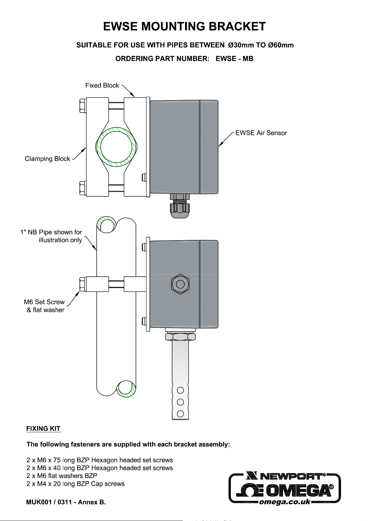
An optional bracket, part number EWSE-MB is avaiable for
pipe mounting. See Annex B for details.
5.0 Electrical Installation
For the EWSE-Pt100-TX temperature sensor with transmitter please
refer to the transmitter manual M4561 for wiring and scaling
information.The standard EWSE-Pt100 model features a 4 way screw
termal block for connection to the 4-wire Pt100 sensor.
Pt100
Page 2

NEWPORT
OMEGA
omega.co.uk
Online Service Internet e-mail
omega.co.uk [email protected]
Servicing Europe:
United Kingdom: OMEGA Engineering Ltd.
ISO 9001 Certified One Omega Drive, River Bend Technology Centre, Northbank
Irlam, Manchester M44 5BD United Kingdom
Free Phone: 0800-488-488 TEL: +44 (0) 161 777-6611
FAX: +44 (0) 161 777-6622 e-mail: [email protected]
France: Managed by the United Kingdom Office
Toll-Free: 0800 466 342 TEL: +33 (0) 161 37 29 00
FAX: +33 (0) 130 57 54 27 e-mail: [email protected]
Benelux: Managed by the United Kingdom Office
Germany/Austria: Daimlerstrasse 26, D-75392 Deckenpfronn, Germany
Toll-Free: 0800 6397678 TEL: +49 (0) 7056 9398-0
FAX: +49 (0) 7056 9398-29 e-mail: [email protected]
It is the policy of OMEGA Engineering, Ltd. to comply with all worldwide safety and EMC/EMI regulations that apply. OMEGA is constantly pursuing certification of its
products to the European New Approach Directives. OMEGA will add the CE mark to every appropriate device upon certification.
The information contained in this document is believed to be correct, but OMEGA accepts no liability for any errors it contains, and reserves the right to alter specifications without notice.
WARNING: These products are not designed for use in, and should not be used for, human applications.
U.S.A.: Omega Engineering, Inc., One Omega Drive, P.O. Box 4047
ISO 9001 Certified Stamford, CT 06907-0047
Canada: 976 Bergar
For immediate technical or application assistance:
United Kingdom: Sales Service Free Phone: 0800-488-488 (UK ONLY)
U.S.A. and Canada: Sales Service: 1-800-826-6342/1-800-TC-OMEGA
Servicing North America:
Laval (Quebec), H7L 5A1 Canada
Toll-Free: 1-800-826-6342 TEL: (514) 856-6928
FAX: (514) 856-6886 e-mail: [email protected]
Sales Service International: +44(0)-161-777-2225
Engineering Service Direct +44(0) -161-777-2232
Customer Service: 1-800-622-2378/1-800-622-BEST
Engineering Service: 1-800-872-9436/1-800-USA-WHEN
®
®
®
WARRANTY/ DISCLAIMER
OMEGA ENGINEERING, LTD. warrants this unit to be free of defects in materials and workmanship for a period of 13 months from date of purchase.
OMEGA’s WARRANTY adds an additional one (1) month grace period to the normal one (1) year product warranty to cover handling and
shipping time. This ensures that OMEGA’s customers receive maximum coverage on each product.
If the unit malfunctions, it must be returned to the factory for evaluation. OMEGA’s Customer Service Department will issue an Authorized Return (AR)
number immediately upon phone or written request. Upon examination by OMEGA, if the unit is found to be defective, it will be repaired or replaced
at no charge. OMEGA’s WARRANTY does not apply to defects resulting from any action of the purchaser, including but not limited to mishandling,
improper interfacing, operation outside of design limits, improper repair, or unauthorized modification. This WARRANTY is VOID if the unit shows
evidence of having been tampered with or shows evidence of having been damaged as a result of excessive corrosion; or current, heat, moisture or
vibration; improper specification; misapplication; misuse or other operating conditions outside of OMEGA’s control. Components in which wear is not
warranted, include but are not limited to contact points, fuses, and triacs.
OMEGA is pleased to offer suggestions on the use of its various products. However, OMEGA neither assumes responsibility for any
omissions or errors nor assumes liability for any damages that result from the use of its products in accordance with information provided
by OMEGA, either verbal or written. OMEGA warrants only that the parts manufactured by the company will be as specified and free of
defects. OMEGA MAKES NO OTHER WARRANTIES OR REPRESENTATIONS OF ANY KIND WHATSOEVER, EXPRESSED OR IMPLIED, EXCEPT
THAT OF TITLE, AND ALL IMPLIED WARRANTIES INCLUDING ANY WARRANTY OF MERCHANTABILITY AND FITNESS FOR A PARTICULAR
PURPOSE ARE HEREBY DISCLAIMED. LIMITATION OF LIABILITY: The remedies of purchaser set forth herein are exclusive, and the total
liability of OMEGA with respect to this order, whether based on contract, warranty, negligence, indemnification, strict liability or otherwise,
shall not exceed the purchase price of the component upon which liability is based. In no event shall OMEGA be liable for consequential,
incidental or special damages.
CONDITIONS: Equipment sold by OMEGA is not intended to be used, nor shall it be used: (1) as a “Basic Component” under 10 CFR 21 (NRC), used in
or with any nuclear installation or activity; or (2) in medical applications or used on humans. Should any Product(s) be used in or with any nuclear
installation or activity, medical application, used on humans, or misused in any way, OMEGA assumes no responsibility as set forth in our basic
WARRANTY/ DISCLAIMER language, and, additionally, purchaser will indemnify OMEGA and hold OMEGA harmless from any liability or damage
whatsoever arising out of the use of the Product(s) in such a manner.
Direct all warranty and repair requests/inquiries to the OMEGA Customer Service Department. BEFORE RETURNING ANY PRODUCT(S) TO
RETURN REQUESTS / INQUIRIES
OMEGA, PURCHASER MUST OBTAIN AN AUTHORIZED RETURN (AR) NUMBER FROM OMEGA’S CUSTOMER SERVICE DEPARTMENT (IN ORDER
TO AVOID PROCESSING DELAYS). The assigned AR number should then be marked on the outside of the return package and on any
correspondence.
The purchaser is responsible for shipping charges, freight, insurance and proper packaging to prevent breakage in transit.
FOR WARRANTY
available BEFORE contacting OMEGA:
1. Purchase Order number under which the product was PURCHASED,
2. Model and serial number of the product under warranty, and
3. Repair instructions and/or specific problems relative to the product.
OMEGA’s policy is to make running changes, not model changes, whenever an improvement is possible. This affords our customers the latest in technology and
engineering. OMEGA is a registered trademark of OMEGA ENGINEERING, LTD.
© Copyright 2011 OMEGA ENGINEERING, LTD. All rights reserved. This document may not be copied, photocopied, reproduced, translated, or reduced to any electronic
medium or machine-readable form, in whole or in part, without the prior written consent of OMEGA ENGINEERING, LTD.
RETURNS, please have the following information
FOR NON-WARRANTY REPAIRS,
consult OMEGA for current repair charges.
Have the following information available BEFORE contacting OMEGA:
1. Purchase Order number to cover the COST of the repair,
2. Model and serial number of the product, and
3. Repair instructions and/or specific problems relative to the product.
Page 3
Page 4
OUTPUT
Type Two wire (4 to 20) mA sink
Limits Low 3.8 mA ; high 21.5 mA
Accuracy ±(mA out / 2000) or ±5 uA which ever greater
Loop Effect ± 0.2 uA / V measured @ 50 Hz 1 V (peak to peak)
Thermal Drift ± 1 uA / °C typical ; ±1.5 uA Max
Max Load [ (Vsupply – 10)/20 ] K_
GENERAL
Update Time 0.5 Seconds
Response Time 1 Second to reach 90% of final value
Start up time From power up typically 5 Seconds
Filter Factor Adaptive
Ambient Temperature (-40 to 85) °C
Connection Screw Terminal
Approvals BS EN 61326 ; 1998 – Electrical equipment for measurement
Factory Default (0 to 100) °C upscale burnout (0.0 °C user trim)
and control ANNEX A ; ANNEX F
3.0 SPECIFICATION @ 20 °C
INPUT
Sensor Type PT100 100 R @ 0°C 2 or 3 Wire
Sensor Range (-200 to +850) ° C (18 to 390) _
Sensor Connection Screw terminal
Minimum span (see note 1) 25 °C
Linearisation BS EN 60751(IEC 751) standard / JISC1604
Accuracy (see note 2) ±0.1 ° C±0.05% of Reading
Thermal Drift 0.0025 % / °C
Excitation current < 200 uA
Lead Resistance effect 0.002 ° C/ _
Maximum lead Resistance 20 _ per leg
Note 1 Any span may be selected, full accuracy is only guaranteed
Note 2 Basic measurement accuracy includes the effects of
for spans greater than the minimum recommended span.
calibration, linearisation and repeatability
If the instrument has been damaged, please notify your supplier immediately.
INSTRUCTION
SHEET
For latest product manuals: omega.co.uk
Shop online at: omega.co.uk e-mail: [email protected]
PUSH BUTTON
PT100 TX
1.0 DESCRIPTION
The TX12 head mounted temperature transmitter connects to any standard pt100
resistance sensor and converts the linearised temperature to a (4 to 20) mA signal. The
transmitter is a two wire device, and is fully configurable by the user, over a wide
temperature range, with the aid of a simple push button. This new TX12 design
incorporates additional configuration menus, allowing the user to push button trim the
transmitter output at both zero and span, ideal for trimming out sensor errors. The
transmitters advanced circuitry guaranties high stability over the wide operating ambient
temperature ranges experienced by head mounted devices.
One of the transmitters features is the program LED, which provides visual indication of
sensor fault when in normal operation and is also used to guide the operator through the
simple menus during configuration.
2.0 RECEIVING AND UNPACKING
Please inspect the packaging and instrument thoroughly for any signs of transit damage.
M4561/0807
MADE IN UNITED KINGDOM
TX12
omega.co.uk
NEWPORT
OMEGA
equipment or loop power supply.
In normal operation the program LED acts as over-range LED.
Figure 2
Menu 1 Range configuration (No Timeout)
Configuration will require the following tools and equipment :-
% DC Supply (12 to 30) V @ 30 mA
% Precision resistance decade box to simulate PT100 sensor.
% Screw driver flat blade 3mm wide
% PT100 resistance tables
% Current meter (user trim)
% Double press button to escape from menus, and return to normal. Normal
% Use single button press to advance selection to “menu 2”, the program LED will
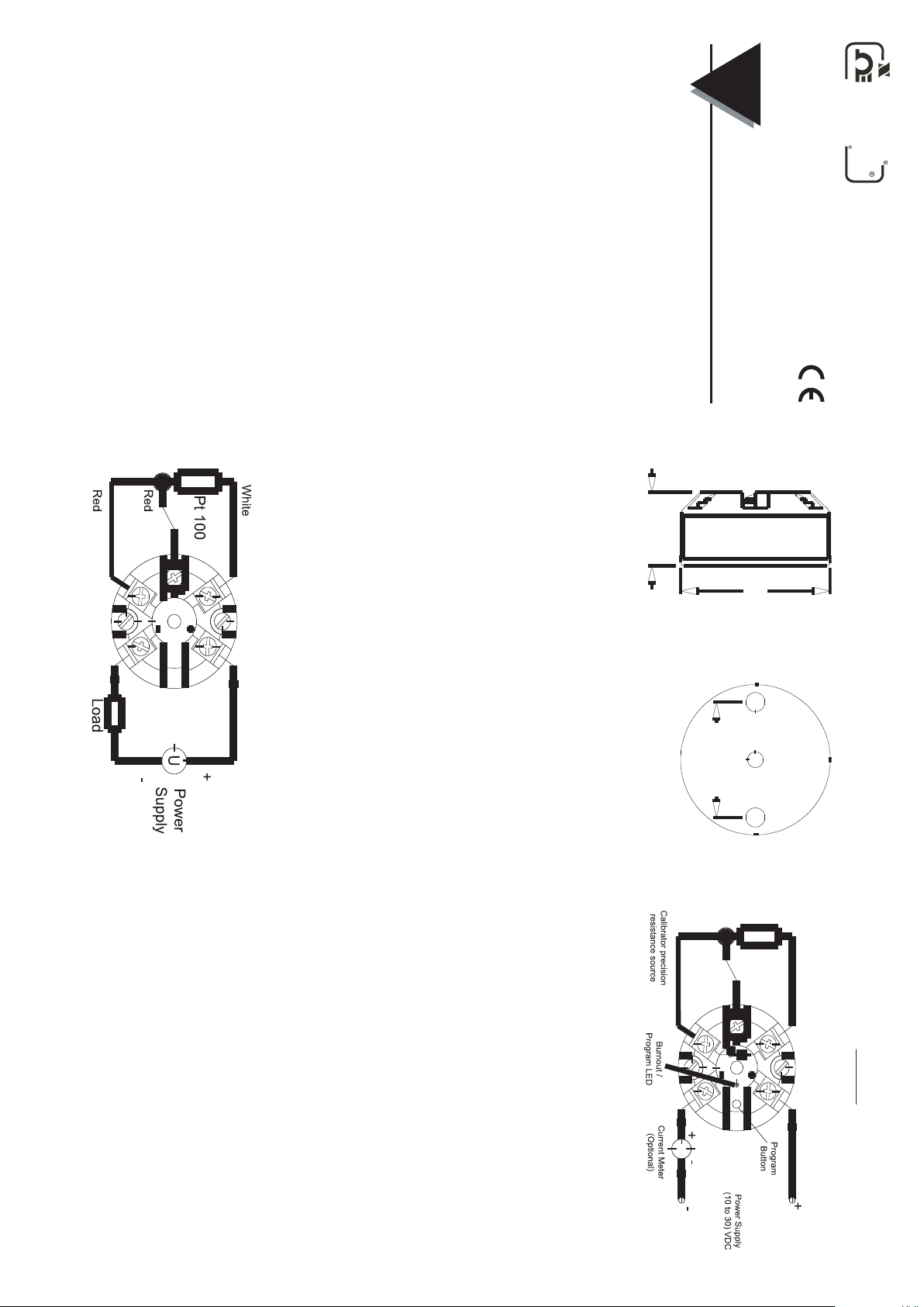
Mounting holes : two holes 5.5 mm diameter, 33 mm centres
Centre Hole sensor wire entry : 4 mm
4.1 Mechanical
The TX12 transmitter has been specifically designed to fit inside a DIN standard probe
head enclosure (such as the Omega NB series), which provides adequate protection
from moisture, dust, corrosive atmosphere etc. All cable entries must be sealed using the
correct size gland. Likewise any probe assembly fitted must be sealed.
Care must be taken when locating the transmitter to ensure the working ambient
temperature range of (-40 to 85) °C is not exceeded. The TX12 enclosure has a centre
hole allowing the sensor wired to enter screw terminals from the transmitter centre, this is
applicable when the sensor is mounted directly below the transmitter.
4.2 Electrical
Electrical connections to the transmitter are made to the screw terminal provided on the
top face. The sensor wires must be equal length and type for the lead compensation to
work correctly. The screw terminals allow for wires to enter either inner or outer direction.
The transmitter is protected against reverse connection and over voltage. If no sensor
(input) connection is made the transmitter will go into either up or down scale output
current, depending on configuration.
Figure 2 gives connection details, the output is shown connected to a 24 V supply. The
load symbol represent any other device connected in the loop, such as Monitoring
equipment , panel indicators and loop isolators. The load value can range from 0 ohms to
the max loop load for given supply, refer to section 3 “Max load” for more information.
The transmitter conforms with EC directive BS EN 61326 : 1998 when correctly installed
in a termination head providing at least IP20 protection and with sensor wires less than 3
metres. Screened or twisted pair wires are recommended for output wires. Always ensure
the (4 to 20 ) mA loop is grounded at one point, this would normally be at the monitoring
PP
Figure 1
number of flashes represents the menu number.
Navigating the menus
% To access menus, press and hold button > 2 second, then program LED will start
% Double press within 0.5 seconds = Escape or change direction
% Press and hold button > two seconds = Enter
%
When a menu is selected the Program LED will flash in bursts of one to three flashes, the
Three types of button press are used:-
% Single button press = Advance
click action.
button use a 3 mm screw driver (flat blade) inserted into the hole. The button has a slight
push button is located under the hole in the keyhole shaped wiring label. To press the
The configuration menus are navigated using the push button and program LED, The
User Configuration
User configuration uses three menus, each menu sets a different parameter:-
Menu 1 Set range
Menu 2 Set direction of output on sensor burnout
Menu 3 User trim at 4 mA and 20 mA.
&(175(6
PP
PP
4.0 INSTALLATION AND WIRING
6,'(9,(: %$6(9,(:
5.0 USER CONFIGURATION
READ COMPLETE SECTION BEFORE ATTEMPTING CONFIGURATION
PARTICULAR CARE SHOULD BE TAKEN REGARDING TIMEOUTS IN MENU 2 & 3
around menus 1 to 3, in the above sequence.
back to menu 1. Repeated single presses will cycle the selected menu back
selected menu to menu 3 and the next single press will advance selected menu
now show two flashes per burst. The Next single presses will advance the
transmitter will not time out and automatically escape from menus.
operation can also be selected by turning transmitter power off and on. Note the
to flash, one flash every burst. This Indicates “menu 1” is selected.
Figure 3 Configuration circuit
IMPORTANT
Page 5

• Press and hold button > 2 seconds to enter menus, menu 1 will then be selected,
• Whilst menu 1 is selected, press and hold button > 2 seconds to enter menu 1, at
• Allow ten seconds then single press button to store low range setting, the program
• Set calibrator to the equivalent resistance of the pt100 sensor, at required high
• Press button to store high range setting, the program LED will flicker for one
check resistance and connection.
indicated by one flash every burst.
which stage the program LED toggle on and off at a slow rate.
LED will now flash at a fast rate.
range temperature and allow ten seconds.
second before the transmitter returns to normal operation. The transmitter is now
re-ranged.
OMEGA’s policy is to make running changes, not model changes, whenever an improvement is
possible. This affords our customers the latest in technology and engineering.
OMEGA is a registered trademark of OMEGA ENGINEERING, INC.
© Copyright 2007 OMEGA ENGINEERING, INC. All rights reserved. This document may not be
copied, photocopied, reproduced, translated, or reduced to any electronic medium or machine-
readable form, in whole or in part, without the prior written consent of OMEGA ENGINEERING, INC.
3. Repair instructions and/or specific
problems relative to the product.
contacting OMEGA:
1. Purchase Order number under which
2. Model and serial number of the product
under warranty, and
the product was PURCHASED,
• Set calibrator to the equivalent resistance of the PT100 sensor, at required low
connection. Connect output to a DC supply, observe polarity. Turn power on and
allow 1 minute warm up period.
range temperature. If the program LED is on at this stage the input is out of range,
The purchaser is responsible for shipping charges, freight, insurance and proper packaging to
prevent breakage in transit.
the following information available BEFORE
FOR WARRANTY
RETURNS, please have
• Current meter (user trim)
To re-range the temperature scale follow the following instructions:-
Direct all warranty and repair requests/inquiries to the OMEGA Customer Service Department.
BEFORE RETURNING ANY PRODUCT(S) TO OMEGA, PURCHASER MUST OBTAIN AN
AUTHORIZED RETURN (AR) NUMBER FROM OMEGA’S CUSTOMER SERVICE DEPARTMENT
(IN ORDER TO AVOID PROCESSING DELAYS). The assigned AR number should then be
marked on the outside of the return package and on any correspondence.
Configuration will require the following tools and equipment :-
• DC Supply (12 to 30) V @ 30 mA
• Precision resistance decade box to simulate PT100 sensor.
• Screw driver flat blade 3mm wide
• PT100 resistance tables
To reset to factory setting, hold the button down whilst the TX12 is powered up.
Range (0 to 100) °C
Burnout up-scale
User trim All user adjustment cleared
Using Menus
• Refer to figure 3, connect resistance box to TX12 input terminals using three wire
• Double press button to escape from menus, and return to normal. Normal
Menu 1 Range configuration (No Timeout)
operation can also be selected by turning transmitter power off and on. Note the
transmitter will not time out and automatically escape from menus.
• To store new setting allow 20 seconds with no button action, the program will then
Reset to factory default settings
If required theTX12 can be reset to factory default setting, this procedure also
removes any user trim adjustment. Factory default settings are :
timeout, store new setting then return to normal operation.
• Use single button press to advance selection to “menu 2”, the program LED will
to flash, one flash every burst. This Indicates “menu 1” is selected.
now show two flashes per burst. The Next single presses will advance the
selected menu to menu 3 and the next single press will advance selected menu
back to menu 1. Repeated single presses will cycle the selected menu back
around menus 1 to 3, in the above sequence.
• Whilst menu 3 is selected, press and hold button > 2 seconds to enter menu 3,
• To change trim direction double press button. The Program LED toggle rate
• To trim output current, single press button to advance current 2 uA in set direction,
select menu 3 indicated by three flashes of the program LED every burst.
which stage the program LED toggle on and off at either a slow rate indicating
downward trim direction or fast rate indicating upwards trim direction.
toggle to the opposite direction. Repeated double presses will toggle between
and down trim direction
or press and hold button to auto advance in set direction release button to stop
advance. Note after approximately 20 seconds of continuous button press,
auto trim rate will speed up. Monitor the current change on the current meter.
• Press and hold button > two seconds = Enter
When a menu is selected the Program LED will flash in bursts of one to three flashes, the
number of flashes represents the menu number.
Navigating the menus
• To access menus, press and hold button > 2 second, then program LED will start
RETURN REQUESTS/INQUIRIES
• Double press within 0.5 seconds = Escape or change direction
Three types of button press are used:-
• Single button press = Advance
• Press and hold button > 2 seconds to enter menus, menu 1 will then be selected,
• Single press button to advance selection to menu 2, and single press again
not within these two bands. Ensure your calibration points are within these bands.
indicated by one flash every burst.
Menu 3 User trim at 4 mA and 20 mA.
The configuration menus are navigated using the push button and program LED, The
push button is located under the hole in the keyhole shaped wiring label. To press the
button use a 3 mm screw driver (flat blade) inserted into the hole. The button has a slight
click action.
• Set
• The transmitter will automatically trim the 4 mA end if the output is within the active
point. Alternatively ensure sensor temperature is at the required calibration point.
band of (3.8 to 6) mA, and trim the 20 mA end if the output is within the active
band of (18 to 21.5) mA. No setting adjustment is performed if the output current
calibrator
to the equivalent resistance of the PT100 sensor, at required
User Configuration
User configuration uses three menus, each menu sets a different parameter:-
Menu 1 Set range
Menu 2 Set direction of output on sensor burnout
Figure 3 Configuration circuit
• To change burnout direction single press button. The Program LED toggle rate will
• To store setting allow 3 seconds with no button action, the program will then
Menu 3 User trim (Timeout is 20 Seconds)
This menu allows the user to trim the output current at 4 mA and 20 mA points,
(similar function to trim potentiometers) and is very useful for trimming out sensor
errors.
The input of the transmitter must be connected to either a calibrator or
temperature sensor held at a known temperature. The (4 to 20) mA loop current
also need to be monitored with a current meter.
• Refer to figure 3, connect sensor or resistance box to TX12 input terminals using
which stage the program LED will either toggle on and off at a slow indicating low
scale burnout or fast rate indicating upscale burnout.
change to the other setting. Repeated single presses will toggle between up and
down scale.
three wire connection. Connect output to a DC supply, observe polarity, connect
current meter in series with loop.Turn power on and allow 1 minute warm
timeout, store new setting then return to normal operation.
5.0 USER CONFIGURATION
READ COMPLETE SECTION BEFORE ATTEMPTING CONFIGURATION
PARTICULAR CARE SHOULD BE TAKEN REGARDING TIMEOUTS IN MENU 2 & 3
IMPORTANT
Menu 2 Burnout Selection (Timeout is 3 Seconds)
• Refer to figure 3, Connect output to a DC supply, observe polarity. For this menu
• Press and hold button > 2 seconds to enter menus, menu 1 will then be selected,
• Single press button to advance selection to menu 2, indicated by two flashes of
• Whilst menu 2 is selected, press and hold button > 2 seconds to enter menu 2, at
the input can be connected or open circuit. Turn power on.
indicated by one flash every burst.
the program LED every burst.
following information available BEFORE
contacting OMEGA:
1. Purchase Order number to cover the
2. Model and serial number of the
3. Repair instructions and/or specific problems
COST of the repair,
product, and
relative to the product.
pH/CONDUCTIVITY
䡺⻬
䡺⻬
䡺⻬
䡺⻬
Controllers, Calibrators, Simulators &
Pumps
Industrial pH & Conductivity
pH Electrodes, Testers & Accessories
Benchtop/Laboratory Meters
䡺⻬
䡺⻬
䡺⻬
䡺⻬
Rotameters, Gas Mass Flowmeters &
Flow Computers
Air Velocity Indicators
Turbine/Paddlewheel Systems
Totalizers & Batch Controllers
Equipment
ENVIRONMENTAL
MONITORING AND CONTROL
䡺⻬
䡺⻬
䡺⻬
䡺⻬
䡺⻬
䡺⻬
pH, Conductivity & Dissolved
Industrial Water & Wastewater
Treatment
Oxygen Instruments
Metering & Control Instrumentation
Refractometers
Pumps & Tubing
Air, Soil & Water Monitors
FOR NON-WARRANTY REPAIRS,
OMEGA for current repair charges. Have the
consult
FLOW/LEVEL
PRESSURE, STRAIN AND FORCE
䡺⻬
䡺⻬
䡺⻬
䡺⻬
䡺⻬
Infrared Pyrometers
Transducers & Strain Gages
Load Cells & Pressure Gages
Displacement Transducers
Instrumentation & Accessories
䡺⻬
䡺⻬
䡺⻬
Wire: Thermocouple, RTD &
Thermistor
Recorders, Controllers & Process
Monitors
Calibrators & Ice Point References
䡺⻬
Thermocouple, RTD & Thermistor
Probes, Connectors, Panels &
Assemblies
䡺⻬
䡺⻬
䡺⻬
䡺⻬
䡺⻬
HEATERS
䡺⻬
䡺⻬
䡺⻬
䡺⻬
䡺⻬
Data Acquisition & Engineering
Software
Communications-Based Acquisition
Systems
Plug-in Cards for Apple, IBM &
Compatibles
Datalogging Systems
Recorders, Printers & Plotters
Heating Cable
Cartridge & Strip Heaters
Immersion & Band Heaters
Flexible Heaters
Laboratory Heaters
TEMPERATURE
Shop online at omega.com
OMEGA…Of Course!
applications.
Where Do I Find Everything I Need for
Process Measurement and Control?
regulations that apply. OMEGA is constantly pursuing certification of its products to the
European New Approach Directives. OMEGA will add the CE mark to every appropriate device
upon certification.
The information contained in this document is believed to be correct, but OMEGA accepts no
liability for any errors it contains, and reserves the right to alter specifications without notice.
WARNING: These products are not designed for use in, and should not be used for, human
DATA ACQUISITION
period.
It is the policy of OMEGA Engineering, Inc. to comply with all worldwide safety and EMC/EMI
or with any nuclear installation or activity, medical application, used on humans, or misused
in any way, OMEGA assumes no responsibility as set forth in our basic WARRANTY /
DISCLAIMER language, and, additionally, purchaser will indemnify OMEGA and hold
OMEGA harmless from any liability or damage whatsoever arising out of the use of the
Product(s) in such a manner.
which liability is based. In no event shall OMEGA be liable for consequential,
incidental or special damages.
CONDITIONS: Equipment sold by OMEGA is not intended to be used, nor shall it be used: (1)
as a “Basic Component” under 10 CFR 21 (NRC), used in or with any nuclear installation or
activity; or (2) in medical applications or used on humans. Should any Product(s) be used in
EXCEPT THAT OF TITLE, AND ALL IMPLIED WARRANTIES INCLUDING ANY
WARRANTY OF MERCHANTABILITY AND FITNESS FOR A PARTICULAR PURPOSE
ARE HEREBY DISCLAIMED. LIMITATION OF LIABILITY: The remedies of purchaser
set forth herein are exclusive, and the total liability of OMEGA with respect to this
order, whether based on contract, warranty, negligence, indemnification, strict
liability or otherwise, shall not exceed the purchase price of the component upon
However, OMEGA neither assumes responsibility for any omissions or errors nor
assumes liability for any damages that result from the use of its products in
accordance with information provided by OMEGA, either verbal or written.
OMEGA warrants only that the parts manufactured by the company will be as
specified and free of defects. OMEGA MAKES NO OTHER WARRANTIES OR
REPRESENTATIONS OF ANY KIND WHATSOEVER, EXPRESSED OR IMPLIED,
with or shows evidence of having been damaged as a result of excessive corrosion; or
current, heat, moisture or vibration; improper specification; misapplication; misuse or other
operating conditions outside of OMEGA’s control. Components in which wear is not
warranted, include but are not limited to contact points, fuses, and triacs.
OMEGA is pleased to offer suggestions on the use of its various products.
Service Department will issue an Authorized Return (AR) number immediately upon phone
or written request. Upon examination by OMEGA, if the unit is found to be defective, it will
be repaired or replaced at no charge. OMEGA’s WARRANTY does not apply to defects
resulting from any action of the purchaser, including but not limited to mishandling,
improper interfacing, operation outside of design limits, improper repair, or unauthorized
modification. This WARRANTY is VOID if the unit shows evidence of having been tampered
workmanship for a period of 13 months from date of purchase. OMEGA’s WARRANTY adds
an additional one (1) month grace period to the normal one (1) year product warranty to
cover handling and shipping time. This ensures that OMEGA’s customers receive maximum
coverage on each product.
If the unit malfunctions, it must be returned to the factory for evaluation. OMEGA’s Customer
OMEGA ENGINEERING, INC. warrants this unit to be free of defects in materials and
WARRANTY/DISCLAIMER
M4498/0607
 Loading...