

Page 1
Series EWDP Wireless Communicating
[18]
Ø15/64
3-29/32
2-9/16
3-3/8
®
Adjustable Differential Pressure Switch
Specications - Installation and Operating Instructions
Bulletin P-EWDP
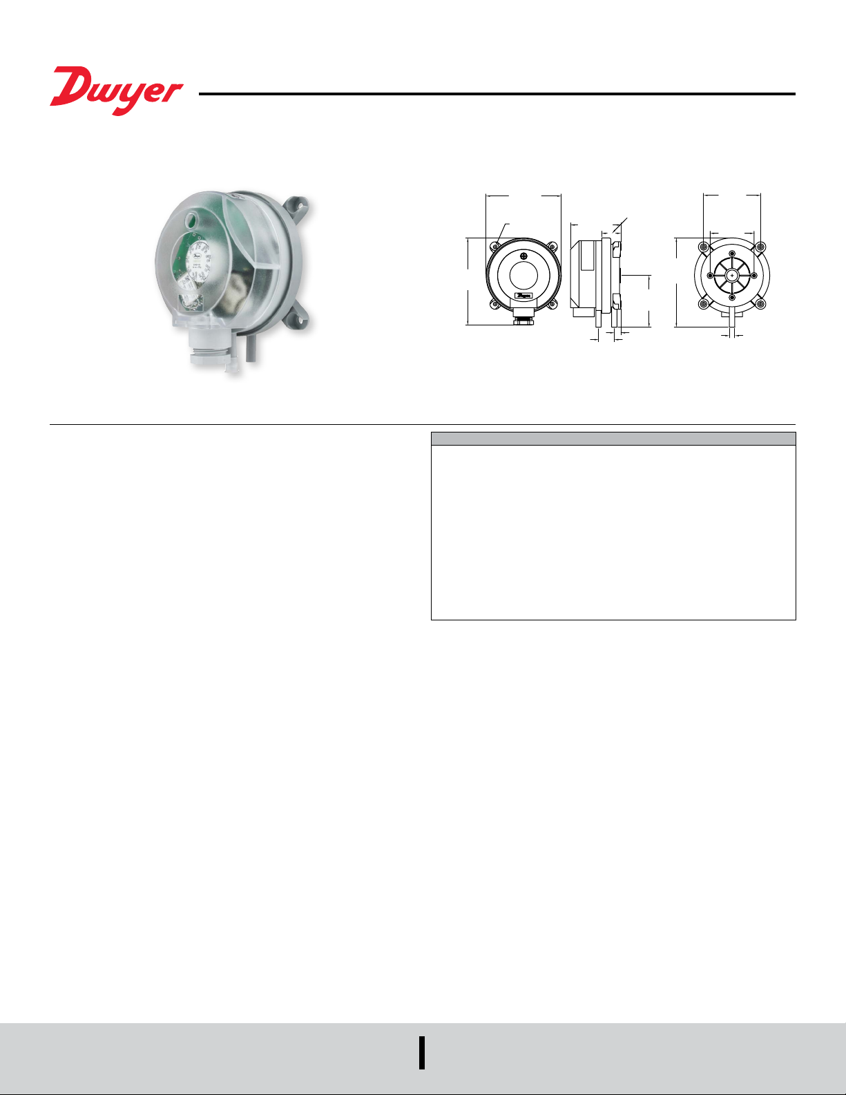
The SERIES EWDP Wireless Communication Adjustable Differential Pressure Switch
uses EnOcean
pressures. The dual scaled adjustment knob in inches of water column and pascals
allows changes to the pressure set point to be made without a pressure gage. The
battery-powered switch is equipped with radio module for frequencies of 902 MHz or
868 MHz which sends a signal wirelessly to a receiver at each change of status. The
silicone diaphragm makes this series ideal for use with air and other noncombustible
gases. The EWDP is available with settings from 0.08 in w.c. (20 Pa) up to 20 in w.c.
(5000 Pa). The compact size, adjustment knob, and wireless capabilities make the
EWDP the perfect choice for HVAC applications in temporary installations or retrots
of existing buildings.
Use only with mediums such as air, or other noncombustible or non-aggressive gases.
Otherwise operating faults or accidents may occur.
MOUNTING
Begin by checking the pressure switch to ensure there is no visible damage to the
housing. If the housing is damaged and may leak, the pressure switch should not be
used.
®
wireless technology to monitor pressure, vacuum, and differential
[85.73]
4x 11/64
[Ø4.45]
[99.10]
SPECIFICATIONS
Service: Air and non-combustible, compatible gases.
Wetted Materials: Diaphragm material: Silicone; Housing material: POM; Switch
body: PA 6.6; Cover: Polystyrene.
Temperature Limits: Process and ambient: 14 to 158°F (-10 to 70°C); Storage: -40
to 185°F (-40 to 85°C).
Pressure Limits: 40 in w.c. (10 kPa).
Process Connections: 5/16˝ (7.94 mm) outside diameter tubing, 1/4˝ (6.0 mm)
inside diameter tubing.
Power Requirements: (1) 3 V CR2032 lithium metal battery, installed nonfunctional, user replaceable (included).
Enclosure Rating: NEMA 3 (IP54).
Mounting Orientation: Vertically, with pressure connections pointing downwards.
Weight: 5.3 oz (150 g).
Agency Approvals: CE.
2-17/64
[57.5]
51/64
7/8
[22]
2-21/64
[59]
19/64
[7.5]
4
[101.54]
[65]
1-31/32
[50]
[Ø6]
Position:
It is recommended that mounting is done in a vertical position with the pressure inlets
pointing downward. If there is no potential for condensation forming, the pressure
switch may be mounted with the pressure ports in a horizontal position. This is not
recommended, and will result in readings that are approximately 0.08 in w.c. higher
than indicated on the adjustment knob. When mounting horizontally, the device
should be mounted lying down with the adjustment knob pointing upwards. Mounting
should not be done with the pressure inlets pointing upwards, as the device will not
be accurate.
Mounting with Screws or Brackets:
1. To mount the pressure switch, L-shaped A-288 and S-shaped A-289 mounting
brackets can be ordered separately. To secure the bracket on the rear side of the
housing, use only the sheet metal screws (3.5 X 8 mm) which are provided with
the bracket. Otherwise, the base of the housing could be punctured resulting in the
pressure switch leaking.
2. The pressure switch can also be mounted directly to a wall. To do this, use screws
with a maximum diameter of 0.315˝ (8.0 mm). Do not over tighten screws allowing the
housing to crack or deform. If cracks or deformation happens, the pressure switch can
leak and readings will not be accurate.
DWYER INSTRUMENTS, INC.
P.O. BOX 373 • MICHIGAN CITY, INDIANA 46360, U.S.A.
Phone: 219/879-8000
Fax: 219/872-9057
www.dwyer-inst.com
e-mail: [email protected]
Page 2
INSTALLING HOSES
IMPORTANT: Pressure hoses cannot be kinked. When running hose over an edge, it
is best to form a loop to ensure the hose will not kink. If the hoses are kinked, pressure
readings will not be accurate.
For hose connection to the switch, use the provided hoses or one with an internal
diameter of 0.25˝ (6.0 mm).
• Connect the hose with the higher pressure to socket P1 which is located in the lower
section of the housing.
• Connect the hose with the lower pressure to socket P2 which is located in the upper
section of the housing.
After installing the hoses, check them for tightness of t at the connection points and
ensure there are no kinks in the line.
SETTING THE PRESSURE RANGE
Removing The Cover:
To remove the cover, unscrew the black housing cover screw located in the recessed
portion of the cover.
LINKING
The Series EWDP Differential Pressure Switches can be linked to Series USB-300
Wireless Receiver and DolphinView Basic software. (For information on that download
process, see the instruction manual for USB-300.) To connect the two units, the EWDP
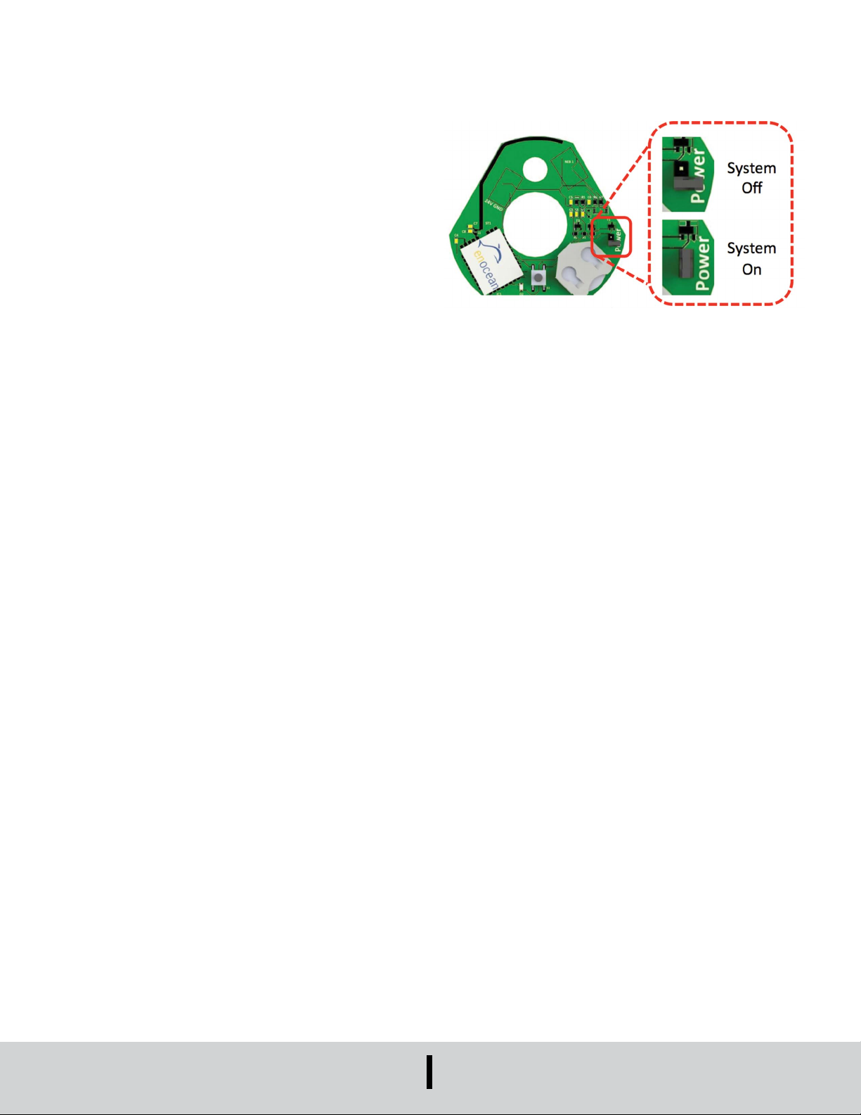
must be turned on. See Figure 1 below to see how the unit should look when it is on.
Adjusting:
Make certain that the jumper is in the ‘system off’ position before carrying out any
pressure adjustments. Refer to Figure 1 for an example of the jumper in an off position.
Using the adjustment knob, set the desired differential pressure to trip the switch.
When the pressure decreases, the switch will return to the resting position as soon as
differential pressure drops below the deadband.
Note: Indications on the dial are only correct for the vertical mounting position.
Attaching The Cover:
Place the cover back on the device, ensuring it is on straight. Using the provided
screw, tighten the cover back onto the housing.
TESTING THE SET POINT
Using a known pressure, slowly raise the pressure until the switch trips, then slowly
lower it again until the device resets.
IMPORTANT: Observe the maximum permissible operating pressure of 40 in w.c. (10
kPa) which is indicated in the data sheet. If this is not followed, damage will occur to
the device.
Figure 1
Once the unit is turned on, plug the USB-300 into the computer being used and open
the DolphinView Basic. Within a few minutes, the EWDP should begin communicating
with the software.
TEST MODE
To test the unit, press the button inside of the cover. For one hour, the LED will ash
with each change of the switch status.
MAINTENANCE/REPAIR
Upon nal installation of the Series EWDP, no routine maintenance is required. The
Series EWDP is not eld serviceable and should be returned if repair is needed. Field
repair should not be attempted and may void warranty.
WARRANTY/RETURN
Refer to “Terms and Conditions of Sale” in our catalog and on our website. Contact
customer service to receive a Return Goods Authorization number before shipping the
product back for repair. Be sure to include a brief description of the problem plus any
additional application notes.
©Copyright 2015 Dwyer Instruments, Inc. Printed in U.S.A. 11/15 FR# 444244-00
DWYER INSTRUMENTS, INC.
P.O. BOX 373 • MICHIGAN CITY, INDIANA 46360, U.S.A.
Phone: 219/879-8000
Fax: 219/872-9057
www.dwyer-inst.com
e-mail: [email protected]
 Loading...