

Page 1
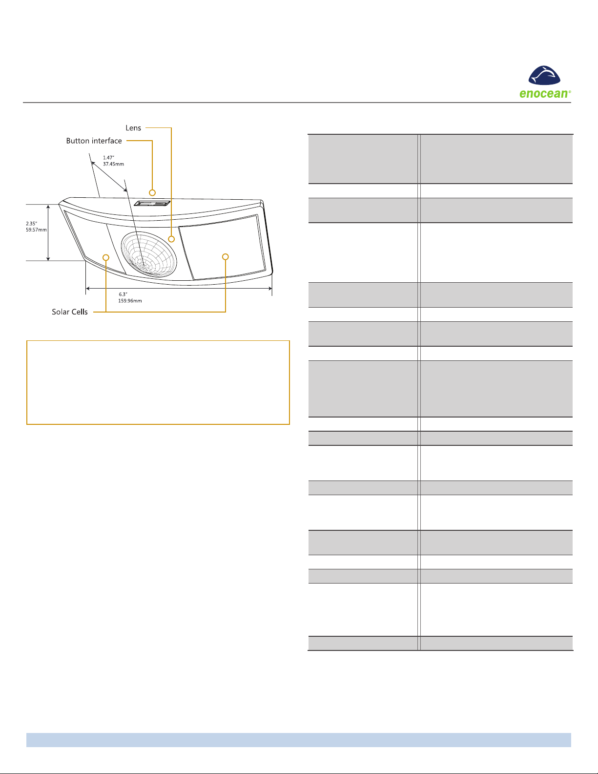
Occupancy Sensor - Ceiling Mounted
Installation Guide
Model: EOSC
Specications (typ. values)
Package Contents
▪ Occupancy Sensor
▪ 2 screws, 2 wall anchors
▪ Wire bracket
Tools Required
▪ Power drill, 3/16” bit
▪ Screwdriver
▪ Light meter
▪ Battery (CR2032) for testing
Product Description
The ceiling-mounted Occupancy Sensor saves energy and adds
convenience by accurately detecting when an area is occupied
or vacant.
This device is wireless, powered by indoor light, and uses a
passive infrared (PIR) sensor to detect motion. The occupancy
sensor transmits RF signals to control lighting, HVAC and outlets
more efciently.
Features Include:
▪ Sends wireless messages to other devices when motion is
detected
▪ Harvests ambient solar energy to power the sensor and wire-
less communication
▪ Mounts easily on any ceiling material
▪ Works with other sensors for enhanced occupancy tracking
▪ Built-in tests to conrm operation at installed location
▪ Supplemental battery or alternative power supply options for
extreme low-light conditions
Power Supply:
Optional:
RF Transmission Range 80 ft. (25 m)
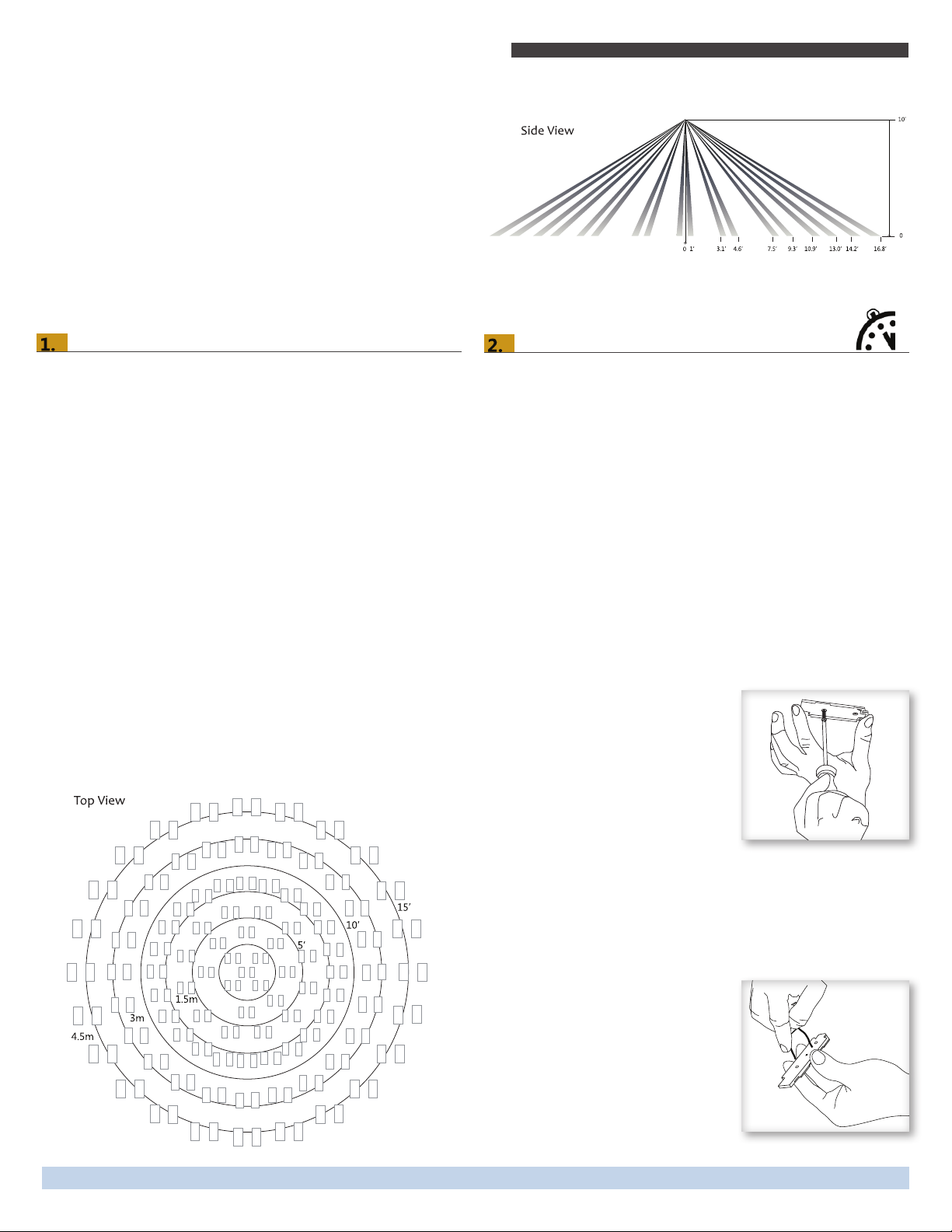
Motion Sensing Range 34 ft. (10 m) diameter
Startup Charge Times*
First motion transmission
/ Linking
Motion LED blink
Light Test / Walk Test
Sustaining Charge Time
for battery free operation
Time to Full Charge* 25 hours @ 200 lux
Operating Life in
Total Darkness
Minimum Operating Light 50 lux (for auto-off only)
Optional Battery Life:
• Infrequent Bright Light
• Consistent Low Light
• Total Darkness
Motion Transmission Interval 2 minutes
Unoccupied Transmission 10 and 30 minutes since last motion
Heartbeat Transmission
Interval (unoccupied)
EnOcean Equipment Prole A5-07-01 (EEP)
RF Communications
Dimensions 6.30” L x 2.35” W x 1.47” D
Weight 4.4 oz. (125 g)
Mounting Height 7-10 feet (2 - 3m) recommended
Environment Indoor use only
Agency Compliance FCC, IC, RoHS, CE, R&TTE
* Natural bright light (2000 lux) or a battery can be temporarily used to
signicantly shorten startup charge times. Specied lux values are for typical
uorescent lighting. Lux level requirements for LED and other types may vary.
For lux reference, OSHA standards require a minimum of 323 lux for ofce
areas.
Indoor light energy harvesting
Supplemental battery (CR2032)
2-wire connector for external power
or remote solar cell (3-5 VDC)
(refer to coverage diagrams)
(operation from empty energy storage)
5 minutes @ 200 lux
1.5 hours @ 2000 lux
3 hours per 24 hours @ 200 lux
80 hours
(after full charge)
20 yrs (with 200 lux for 2 hrs/day, 7 days/week)
15 yrs (with 65 lux for 5 hrs/day, 7 days/week)
6.5 yrs
Disabled by default
Enabled = heartbeat @ 1 hr interval
(after unnocupied messages)
EnOcean 902 MHz (EOSCU)
EnOcean 868 MHz (EOSCA)
(160mm x 60mm x 37mm)
14° to 104°F (-10° to 40°C)
20% to 95% relative humidity
(non-condensing)
Page 1© 2015 EnOcean GmbH
Page 2
Occupancy Sensor – Ceiling Mounted • Installation Guide
Functional Description
If motion is detected by the permanently active PIR sensor, a
radio telegram indicating the occupied status will transmit immediately. A transmission interval timer starts to run with a 2
minute lockout timer. No radio telegrams will be sent out until
the timer expires.
After the timer has expired, the unit will transmit occupancy
upon new motion detection. An unoccupied message will be
sent if no motion is detected for an extended period - sending
the rst at 10 minutes, then again at 30 minutes. A heartbeat
message can also be enabled.
To provide coverage for very high ceilings, a wall sensor can be
incorporated in the plan for complete coverage.
Planning
Take a moment to plan for the sensor’s successful operation and
optimal communication with other system components.
Remove the sensor from its packaging and place it under a
bright light to provide the required startup charge. Optionally,
to ensure the sensor energy storage is fully charged, insert a
CR2032 battery for 5 minutes while in a well-lit location.
▪ Ensure the location provides consistent and adequate light
▪ Locate the sensor between 7 - 10 ft (2.1 to 3 m) high
▪ Avoid installed near ceiling fan or hanging light xtures
▪ Consider the area’s trafc patterns and principal use, for
example, walking, working, lounging or sleeping
▪ Provide a minimum clearance of 4 ft. (1.2 m) away from heat
sources, light bulbs, forced air, or ventilation systems
▪ Consider the construction materials (such as metal) in the
space and obstacles that may interfere with RF signals
Sensor Range
A single occupancy sensor provides sufcient coverage for most
applications. For some applications, multiple sensors may be
required to provide complete coverage.
Coverage Diagrams
Installing
The occupancy sensor can be mounted on most ceilings with
the provided screws, or mounted on dropped ceilings, using the
provided wire bracket.
NOTE: It is often easier to link the sensor before it is mounted
on the ceiling. Refer to the “Linking” section.
1. Decide where you want to install the occupancy sensor.
Tip: For visual alignment, orient the sensor parallel to one of
the walls.
2. Remove the mounting plate from the sensor.
3. Decide which of the two installation options is appropriate.
A. Screw Mounting Plate to the Ceiling
i. Hold the mounting plate in place on the ceiling and
use a pencil to lightly mark two small dots for the
screw drill points.
ii. Drill two holes with a 3/16” drill bit and insert
the wall anchors.
iii. Insert the rst screw
loosely and level the
mounting plate.
iv. Insert the second screw
and then hand-tighten
the rst screw.
estimated time: 20 minutes
B. Mount Using the Wire Bracket
i. Remove the ceiling tile where you want to
mount the sensor.
ii. Place the mounting plate squarely on the ceiling tile
and use the wire to mark two points for the holes.
iii. Punch two small holes
through the ceiling tile at
the marked points.
iv. Insert the wire bracket
through the two holes in
the mounting plate.
Make sure the ends are
roughly even.
Page 2© 2015 EnOcean GmbH
Page 3
Occupancy Sensor – Ceiling Mounted • Installation Guide
v. Feed the wires through the
holes in the ceiling tile.
vi. On the front of the ceiling
tile, atten the wire bracket
so it is snug against the
mounting plate.
vii. On the back of the ceiling
tile, twist the wires together
to hold the mounting plate
securely.
viii. Replace the ceiling tile.
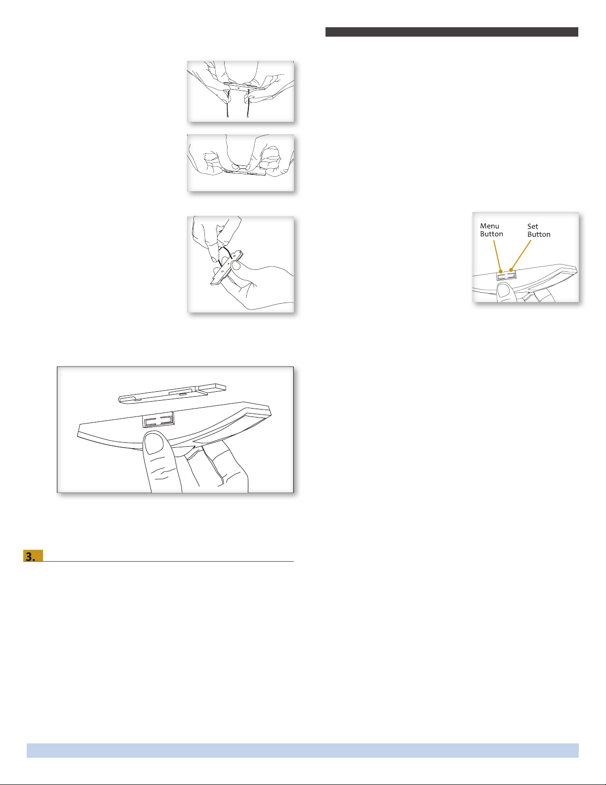
4. Attach the sensor to the mounting plate.
With the 2-button interface facing you, slide the sensor to
the left on the mounting plate until it snaps into place.
The Occupancy Sensor is a Transmit-only Device.
To link the occupancy sensor to a transceiver; the transceiver
must rst be powered, within wireless range of the sensor, and
set to accepts links.
Next, the desired transmitter, or another transceiver, is triggered
to send a special link message. The awaiting transceiver receives
and stores the link permanently so the devices can interact to
provide a variety of intelligent control options.
To Link or Unlink an Occupancy Sensor
1. Set the desired transceiver to the desired Link/Unlink mode.
(refer to that device’s installation guide).
2. Click the Menu button on the
bottom of the sensor once. This
sends a link/unlink radio
telegram.
NOTE: The button interface on the
sensor is used for linking and
testing only. The occupancy timer
settings are congured on the
transceiver to which the sensor is linked.
Refer to the “Linking” section of the transceiver/controller
installation guides to complete the linking & setup process.
5. Conrm the sensor is properly positioned to detect motion
and has sufcient light to operate - refer to the “Walk Test”
and “Light Test” sections.
Linking
Two or more compatible devices can be linked and congured
to provide the desired control. There are two basic types of
devices in the system; transmitters and transceivers.
▪ Transmit-only: Transmitters are simple energy-harvesting
devices that send RF messages to communicate a condition,
level, or state. Transmitters can only be linked to transceivers.
Examples > Rocker Switches, Occupancy Sensors
▪ Transmit & Receive: Transceivers are controlling devices
that send as well as receive RF messages. They also process
relevant control logic, and actuate the appropriate outputs
(switching a light on or off for example). Transceivers can be
linked with transmitters as well as other transceivers.
Examples > Relays, Dimmers, Gateways
Testing the Sensor
Before starting a test, ensure the sensor’s energy storage is fully
charged by placing it under bright light (2000 lux) for 1.5 hours,
or insert a battery for 5 minutes while in a well-lit area.
NOTE: If the sensor does not have a sufcient charge, it cannot
enter into the test modes. No LED light or 1 red blink when the
set button is pressed indicates insufcient charge.
If a battery is used to charge the sensor for a light test, ensure it
is removed to get an accurate light measurement.
A test mode will stay active for 3 minutes. To exit a test and
resume normal operation, press and hold the Menu button for 5
seconds.
Walk Test
Use the walk test to conrm that motion is within the sensor’s
range.
1. Press and hold the Set button for 5 seconds.
••> Red LED will blink to conrm that a walk test is active.
2. Move in and out of the sensor‘s range to determine its coverage area.
••> Sensor will blink when it detects motion.
3. Make small hand movements just inside the limit of the sensor‘s range to see if the motion triggers a response.
NOTE: Ensure the sensor does not falsely trigger from user
activity outside the desired zone or other heat and motion
sources. If false triggering occurs, adjust the sensitivity switch
(next to the battery slot) from REG to LOW.
Page 3© 2015 EnOcean GmbH
Page 4
Occupancy Sensor – Ceiling Mounted • Installation Guide
Light Test
Use the light test to measure real-time light levels and conrm
whether the occupancy sensor has sufcient light.
1. Create a realistic lighting condition (the test measures the
real-time light level).
2. Press and hold the Set button for 10 seconds.
••> Red & green LEDs will blink to conrm light test is active.
3. Watch the LED blink rate to determine the light strength.
••> The highest is 5 blinks which indicates very good light
(200 lux or more). 1 blink indicates minimum light (<25 lux).
NOTE: If there is no blink rate, consider relocating the sensor or
installing a battery to provide supplemental power.
Optional Settings
Two additional settings can be congured via button presses
which may be useful in some installations. Note that these
settings consume additional energy and are not advisable for
low-light level installations:
LED Blink on Motion Transmision - Red LED under PIR lense
will blink whenever motion is transmitted (disabled by default).
••> To enable/disable - press and hold Menu button for
3 seconds (green Menu LED will blink once)
-Enabled = 3 blinks from green Menu LED
-Disabled = 3 blinks from red Set LED
Heartbeat Transmision - unoccupied heartbeat message will
be sent at 1 hr intervals with no motion (disabled by default).
••> To enable/disable - press and hold Menu button for
5 seconds (both green and red LEDs will blink once)
-Enabled = 3 blinks from green Menu LED
-Disabled = 3 blinks from red Set LED
Supplemental Power (optional)
In areas with consistently low lighting, or prolonged periods of
darkness, battery power (CR2032) or an auxilliary 3-5 VDC power source can be used to supplement the solar energy harvester.
1. Remove the sensor from the mounting plate and identify the
battery holder and auxilliary power connector on the circuit
board
2. A. Insert the battery under the clip with the positive pole (+)
up and press it in place
3. B. Or insert the 3-5 VDC + and - leads into the appropriate
screw terminals.
4. Remount the sensor on the mounting plate.
Troubleshooting
Problem Solution Checklist
Sensor does not
generate a wireless
message
Sensor is activated
when there is nothing to detect
Linked device does
not respond to
wireless messages
Explanation of
Occupied & Heartbeat Message Data
Telegrams
902 MHz:
This device complies with part 15 of the FCC rules and Industry Canada ICES-003. Operation
is subject to the following two conditions: (1) This device may not cause harmful interference,
and (2) this device must accept any interference received, including interference that may
cause undesired operation.
IMPORTANT! Any changes or modications not expressly approved by the party responsible
for compliance could void the user’s authority to operate this equipment.
Le présent appareil est conforme aux CNR d’Industrie Canada applicables aux appareils radio
exempts de licence. L’exploitation est autorisée aux deux conditions suivantes: (1) l’appareil ne
doit pas produire de brouillage, et (2) l’utilisateur de l’appareil doit accepter tout brouillage
radioélectrique subi, meme si le brouillage est susceptible d’en compromettre le fonctionnement.
IMPORTANT! Tous les changements ou modifications pas expressément approuvés par la
partie responsable de la conformité ont pu vider l’autorité de l’utilisateur pour actioner cet
équipment.
▪ Press Set button to transmit motion message
▪ Verify the LED blinks when motion is detected
during a walk test
▪ Verify the solar cell is charged properly
▪ Verify there is 4 ft. (1.2 m) clearance from heat
sources that may disturb sensing
▪ Reduce sensitivity setting by moving the PIR
sensitivity switch on the back from REG to
LOW (the left-hand position)
▪ Force motion message by pressing Set button
▪ Check for environment or range issues
▪ Verify the device is linked
▪ Check the transceiver connection and the wir-
ing for errors
▪ Check if appropriate devices are linked accord-
ing to good system planning
Data Byte 3: Super Capacitor Voltage, 0-250 (0-5V)
Data Byte 2: Solar Panel Current, 0-127 microA
Data Byte 1: 0xFF (occupied) or 0x00 (unoccupied)
Data Byte 0: 0x09 (wall sensor) 0x0B (ceiling sensor)
contains:
FCC: SZV-STM300U
IC: 5713A-STM300U
Page 4© 2015 EnOcean GmbH
V2.4 XOSCIGEOC
 Loading...