

Page 1
User’s Guide
Shop online at
omega.com
e-mail: [email protected]
For latest product manuals:
omegamanual.info
®
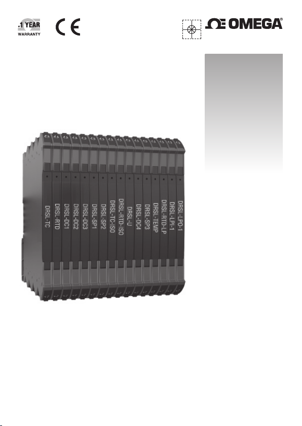
DRSL SERIES DIN RAIL ISOLATORS
and SIGNAL CONDITIONERS
DRSL-TC, DRSL-RTD, DRSL-TC-ISO,
DRSL-RTD-ISO, DRSL-TEMP,
and DRSL
-RTD-LP
Page 2

omega.com [email protected]
Servicing North America:
U.S.A.: Omega Engineering, Inc., One Omega Drive, P.O. Box 4047
Stamford, CT 06907-0047 USA
Toll-Free: 1-800-826-6342 (USA & Canada only)
Customer Service: 1-800-622-2378 (USA & Canada only)
Engineering Service: 1-800-872-9436 (USA & Canada only)
Tel: (203) 359-1660 Fax: (203) 359-7700
e-mail: [email protected]
For Other Locations Visit omega.com/worldwide
The information contained in this document is believed to be correct, but OMEGA accepts no
liability for any errors it contains, and reserves the right to alter specifications without notice.
WARNING: These products are not designed for use in, and should not be used for, human
applications.
Page 3

DRSL SERIES OF
TEMPERATURE SIGNAL CONDITIONERS
DRSL-TC / DRSL-RTD / DRSL-TC-ISO / DRSL-RTD-ISO /
DRSL-TEMP / DRSL-RTD-LP
CONTENTS
Warning ...................................................................................................................... 2
Safety instructions ................................................................................................ 3
Mounting on DIN rail ............................................................................................. 5
Installation on DIN rail ......................................................................................... 6
Module stop ............................................................................................................. 6
Flexible supply ........................................................................................................ 7
Marking ...................................................................................................................... 8
Side label ................................................................................................................... 8
Applications.............................................................................................................. 9
Technical characteristics ..................................................................................... 9
Mounting / installation ........................................................................................ 9
Order codes: ............................................................................................................. 10
Specifications .......................................................................................................... 10
DIP-switch configuration .................................................................................... 13
Temperature range programming.................................................................... 14
Front LED Indications ........................................................................................... 15
Block diagram and wiring ................................................................................... 16
1
Page 4
GENERAL
HAZARD-
OUS
VOLTAGE
CAUTION
To avoid the risk of electric shock and fire, the safety instructions
of this guide must be observed and the guidelines followed. The
specifications must not be exceeded, and the device must only be
applied as described in the following. Prior to the commissioning
of the device, this installation guide must be examined carefully.
Only qualified personnel (technicians) should install this device.
If the equipment is used in a manner not specified by the
manufacturer, the protection provided by the equipment may
be impaired. Until the device is fixed, do not connect hazardous
voltages to the device.
Repair of the device must be done by OMEGA Engineering only.
In applications where hazardous voltage is connected to in-/
outputs of the device, sucient spacing or isolation from wires,
terminals and enclosure - to surroundings (incl. neighbouring
devices), must be ensured to maintain protection against electric
shock.
Potential electrostatic charging hazard. To avoid the risk of
explosion due to electrostatic charging of the enclosure, do not
handle the units unless the area is known to be safe, or appropriate
safety measures are taken to avoid electrostatic discharge.
SYMBOL IDENTIFICATION
Triangle with an exclamation mark: Read the manual
before installation and commissioning of the device in
order to avoid incidents that could lead to personal injury or
mechanical damage.
The CE mark proves the compliance of the device with the
essential requirements of the directives.
WARNING
2
Page 5

SAFETY INSTRUCTIONS
RECEIPT AND UNPACKING
Unpack the device without damaging it. The packing should always follow the
device until this has been permanently mounted. Check at the receipt of the device
whether the type corresponds to the one ordered.
ENVIRONMENT
Avoid direct sunlight, dust, high temperatures, mechanical vibrations and shock, as
well as rain and heavy moisture. If necessary, heating in excess of the stated limits
for ambient temperatures should be avoided by way of ventilation.
Can be used in overvoltage Category II and Pollution Degree 2. The devices are
designed to be safe at least under an altitude up to 2 000 m.
MOUNTING
Mounting and connection of the device should comply with national legislation for
mounting of electric materials, i.e. wire cross section, protective fuse, and location.
Descriptions of input / output and supply connections are shown in this installation
guide and on the side label.
The device is provided with field wiring terminals and shall be supplied from a Power
Supply having double / reinforced insulation. A power switch should be easily accessible
and close to the device. The power switch shall be marked as the disconnecting unit
for the device.
DRSL Series must be mounted on a DIN rail according to EN 60715.
UL installation
Use 60/75°C copper conductors only.
Wire size ................................... AWG 26-12
UL file number........................ E70366
The device is an Open Type Listed Process Control Equipment. To prevent injury
resulting from accessibility to live parts the equipment must be installed in an
enclosure.
The power Supply unit must comply with NEC Class 2, as described by the National
Electrical Code
®
(ANSI / NFPA 70).
3
Page 6

Cleaning
When disconnected, the device may be cleaned with a cloth moistened with
distilled water.
4
Page 7
MOUNTING ON DIN RAIL
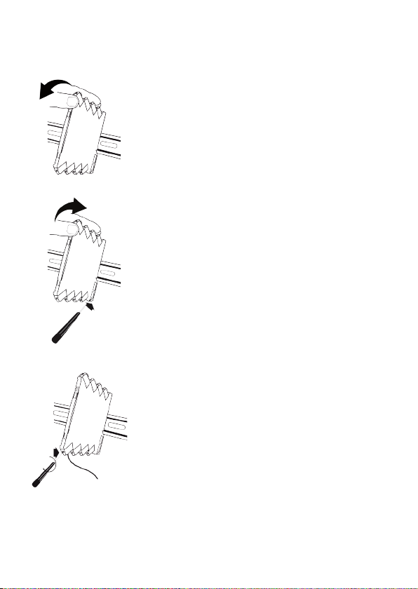
The DRSL devices can easily be mounted on a
standard 35 mm DIN rail.
Remove the DRSL Series units from the rail by lifting
the DIN rail mounting clip.
2
Wire size AWG 26-12 / 0.13 x 2.5 mm
Screw terminal torque 0.5 Nm.
stranded wire.
5
Page 8
INSTALLATION ON DIN RAIL
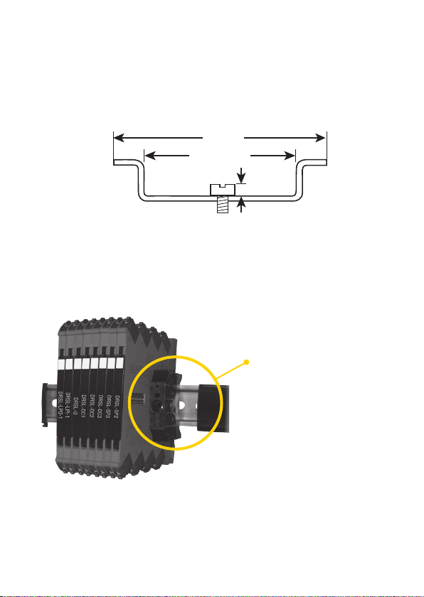
To avoid short circuit between the power rail connectors on the DRSL-TC-ISO
and DRSL-RTD-ISO devices and the screws holding the 7.5 mm DIN rail, the head
of the screws shall be no more than 3.5 mm high.
35 mm
> 24 mm
< 3,5 mm
MODULE STOP
Module stop
(DRSL-MOD-STOP)
6
Page 9
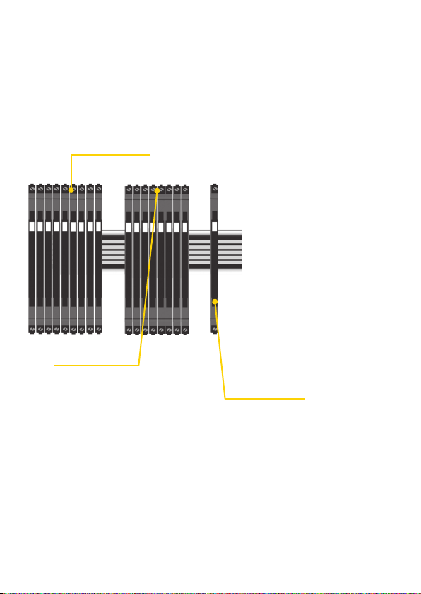
FLEXIBLE SUPPLY
The DRSL-TC, DRSL-RTD, DRSL-TC-ISO,
and DRSL-RTD-ISO devices are powered
by 24 VDC +/- 30%. 2.5 A equals 60 W - this
means that up to 85 units can be energized
by connecting the source in parallel
with the power terminals of each unit.
External protective fuse: 2.5 A.
Power rail solution:
Alternately, you can connect 24 VDC
to one DRSL-TC-ISO or DRSL-RTDISO device, which will energize up
to 10 other units on the power rail.
External protective fuse: 0.4 A.
DRSL-PCU
Power rail solution:
The DRSL-PCU power connector unit
allows easy connection of your 24 VDC/
2.5 A source to the power rail. Up to
85 of the DRSL-TC-ISO and DRSL-RTDISO units can be powered this way.
External protective fuse: 2.5 A.
External fuse characteristics:
The 2.5 A fuse must break after not more than 120 seconds at 6.4 A.
7
Page 10
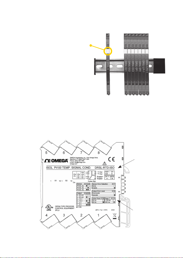
MARKING
The hinged cover of the DRSL series has
a space designed to accept a snap-on
marker, which can be used to identify
individual units.
This space measures 5 x 7.5 mm, and
markers from Weidmuller’s MultiCard
System, type MF 5/7.5, are suitable.
SIDE LABEL
Terminal numbers
}
Type no.
Pin
connections
}
Approvals
8
}
DIP-switch
}
settings
Page 11

TEMPERATURE SIGNAL CONDITIONERS
• Converts process measurements from Pt100, TC J and K temperature
sensors to voltage or current outputs
• Multiple pre-calibrated temperature ranges are selectable via
DIP-switches
• High accuracy < 0.05% and excellent 50/60 Hz noise suppression
• Fast signal response time < 30 ms
• Slimline 6 mm housing
Applications
• The temperaturesignal conditioners measurestandard2-, 3- or 4-wire Pt100
and/or TC J & K temperature sensors, and provides an analog voltage or current
output.
• High3portisolationinthetypesDRSL-TC-ISOandDRSL-RTD-ISOprovidesurge
suppression and protects the control system from transients and noise.
• The loop powered devices type DRSL-TEMP also have high 2-port galvanic
separation to eliminate ground loops.
Technical characteristics
• Highconversionaccuracy,betterthan0.05%ofselectedrange.
• A visible green LED indicates operational status of the DRSL-TC, DRSL-RTD,
DRSL-TC-ISO AND DRSL-RTD-ISO units and status of the input sensor.
• Allterminalsareprotectedagainstovervoltageandpolarityerror.
• Meeting the NAMUR NE21 recommendations, the DRSL devices ensure top
measurement performance in harsh EMC environments.
• ThedevicesmeettheNAMURNE43standarddefiningout ofrangeandsensor
error output values.
• High galvanic isolation of 2.5 kVAC (DRSL-TC-ISO, DRSL-RTD-ISO, AND DRSL-
TEMP).
• Excellentsignal/noiseratioof>60dB.
Mounting / installation
• Easyconfigurationofmore than 1000 factorycalibrated measurementranges
using DIP-switches.
• Thenarrow6 mmhousingand very lowpower consumptionallows upto165
units to be mounted per meter of DIN rail, without any air gap between units.
• Widetemperatureoperationrangeof-25...+70°C.
9
Page 12
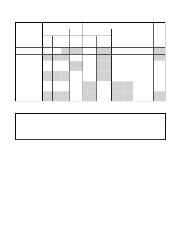
Order codes:
Input Output
DRSL-TC
DRSL-RTD
DRSL-TC-ISO
DRSL-RTD-ISO
DRSL-TEMP
DRSL-RTD-LP
TC Pt100 Current
Int.
Ext.
CJC
2-, 3-,
CJC
Active Passive
4-wire
J & K
Volt-
age
LED Supply
24 VDC
24 VDC
24 VDC /
power rail
24 VDC /
power rail
Loop-
powered
Loop-
powered
Accessories
Type Function
DRSL-PCU
DRSL-PWR-RAIL
DRSL-MOD-STOP
Power rail connector unit - DRSL-TC-ISO, DRSL-RTD-ISO
Power rail - 7.5 or 15 mm - DRSL-TC-ISO, DRSL-RTD-ISO
Module stop
Specifications
Environmental conditions:
Specifications range ............................................... -25°C to +70°C
Storage temperature .............................................. -40°C to +85°C
Calibration temperature ........................................ 20...28°C
Relative humidity..................................................... <95%RH(non-cond.)
Protection degree .................................................... IP20 / EN60529
Installation .................................................................. Pollution degree 2 and
overvoltage category II
Mechanical specifications:
Dimensions(HxWxD) .............................................. 113 x 6.1 x 115 mm
Weight approx. .......................................................... 70 g
DIN rail type ............................................................... DIN EN 60715 - 35 mm
Wire size ...................................................................... 0.13...2.5 mm
AWG 26...12 stranded wire
Screw terminal torque ........................................... 0.5 Nm
2
/
Isola-
ted
2.5 kV
2.5 kV
2.5 kV
10
Page 13

Common electrical specifications:
Supply voltage, 24 VDC nom. ............................. 16.8...31.2 VDC
Power consumption, max. .................................... 0.7 W
Loop-powered:
DRSL-TEMP ........................................................... 5.5...35 VDC
DRSL-RTD-LP ........................................................ 3.3...35 VDC
Isolation voltage, test ............................................ 2.5 kVAC (reinforced)
Isolation voltage, working .................................... 300 VAC / 250 VAC
Signal / noise ratio .................................................. >60dB
Signal dynamics, input ........................................... 23 bit
Signal dynamics, output ....................................... 18 bit
Response time, fixed or selectable .................. < 30 ms / 300 ms
Incorrect DIP-sw setting identification:
Supplied ....................................................................... 0V/0mAoutput;LED0.5s/1Hz
Loop-powered ........................................................... 3.5 mA output
Accuracy - the greater of the basic and general value is valid
Device Input
DRSL-RTD-ISO
DRSL-TEMP
DRSL-TC-ISO
DRSL-TEMP
DRSL-RTD,
DRSL-RTD-LP
DRSL-TC TC ≤ 1°C
Pt100 ≤ 0.1°C
TC ≤ 0.5°C
Pt100 ≤ 0.2°C
Basic
accuracy
General
accuracy
≤ ± 0.05%
of selected
range
≤ ± 0.1%
of selected
range
Temperature
coefficient
0.02°C/°C (basic) or
≤ ± 0.01% of selected range/°C
0.1°C/°C (basic) or
≤ ± 0.01% of selected range/°C
0.02°C/°C (basic) or
≤ ± 0.01% of selected range/°C
0.1°C/°C (basic) or
≤ ± 0.01% of selected range/°C
EMC immunity influence ....................................... < ±0.5% of selected range
Extended EMC immunity:
NAMUR NE 21 ........................................................... < ±1% of selected range
Input specifications:
Specifications for Pt100 input:
Temperature range, Pt100 .................................. -200...+850°C - IEC 60751
Sensor current ........................................................... < 150 mA
Sensor cable resistance ........................................ < 50 W per wire
Effect of sensor cable resistance, 3- / 4-wire .... < 0.002 Ω / Ω
Sensor error detection ........................................... Yes - selectable
Shorted sensor detection ............................... < 18 Ω
Broken sensor detection ................................. >800Ω
11
Page 14
Specifications for TC input:
Temperature range, TC J ........................................ -100...+1200°C - IEC 60584-1
Temperature range, TC K ...................................... -180...+1372°C - IEC 60584-1
Sensor cable resistance ........................................ < 5 kΩ per wire
Cold junction compensation (CJC) accuracy:
Accuracy @ external Pt100 ................................. Beter than ±0.15°C
Accuracy @ internal CJC ......................................... Better than ±2.5°C
Open Thermocouple detection ........................... Yes – selectable
Internal CJC error detection ................................. Yes
External CJC error detection ................................ Yes – selected
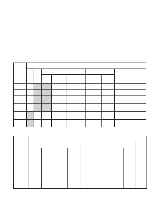
Output specifications:
Current output
DRSL-TC
DRSL-RTD
DRSL-TC-
ISO
DRSL-
RTD-ISO
DRSLTEMP
DRSL-
RTD-LP
Active
Invert Range Limit
Passive
Selectable NAMUR NE43
Sensor
error
0/4...20 mA 0/3.8...20.5 mA 0/3.5/23 mA
0/4...20 mA 0/3.8...20.5 mA 0/3.5/23 mA
0/4...20 mA 0/3.8...20.5 mA 0/3.5/23 mA
0/4...20 mA 0/3.8...20.5 mA 0/3.5/23 mA
4...20 mA 3.8...20.5 mA 3.5 / 23 mA
4...20 mA 3.8...20.5 mA 3.5 / 23 mA
Range
4...20 mA
Max. load
600 W @ 21 mA
600 W @ 21 mA
600 W @ 21 mA
600 W @ 21 mA
(V
supply
(V
supply
-5.5)/0.023 [W]
-3.3)/0.023 [W]
Load stability ............................................................. ≤ 0.01% of span / 100 Ω
Selectable voltage output
Low range High range
Range Limit
Sensor
error
Range Limit
DRSL-TC 0/1...5 V 0/0.875...5.125 V 0/5.5 V 0/2...10 V 0/1.75...10.25 V 0/11 V 10 kW
DRSL-
0/1...5 V 0/0.875...5.125 V 0/5.5 V 0/2...10 V 0/1.75...10.25 V 0/11 V 10 kW
RTD
DRSL-TC-
0/1...5 V 0/0.875...5.125 V 0/5.5 V 0/2...10 V 0/1.75...10.25 V 0/11 V 10 kW
ISO
DRSL-
0/1...5 V 0/0.875...5.125 V 0/5.5 V 0/2...10 V 0/1.75...10.25 V 0/11 V 10 kW
RTD-ISO
Sensor
error
Min.
load
12
Page 15
Approvals:
EMC 2004/108/EC .................................................. EN 61326-1
EMC Emission............................................................. CISPR 22, Class B
LVD 2006/95/EC ...................................................... EN 61010-1
UL, Standard for Safety ......................................... UL 61010-1
Safe Isolation ............................................................. EN 61140
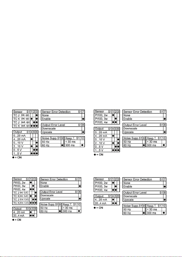
DIP-SWITCH CONFIGURATION
DRSL-RTD and DRSL-RTD-ISO - Pt100DRSL-TC and DRSL-TC-ISO - TC J & K
*DRSL-TC - only int CJC
DRSL-TEMP - Pt100 & TC J/K DRSL-RTD-LP - Pt100
(Power must be cycled after DIP-switch positions are changed).
13
Page 16
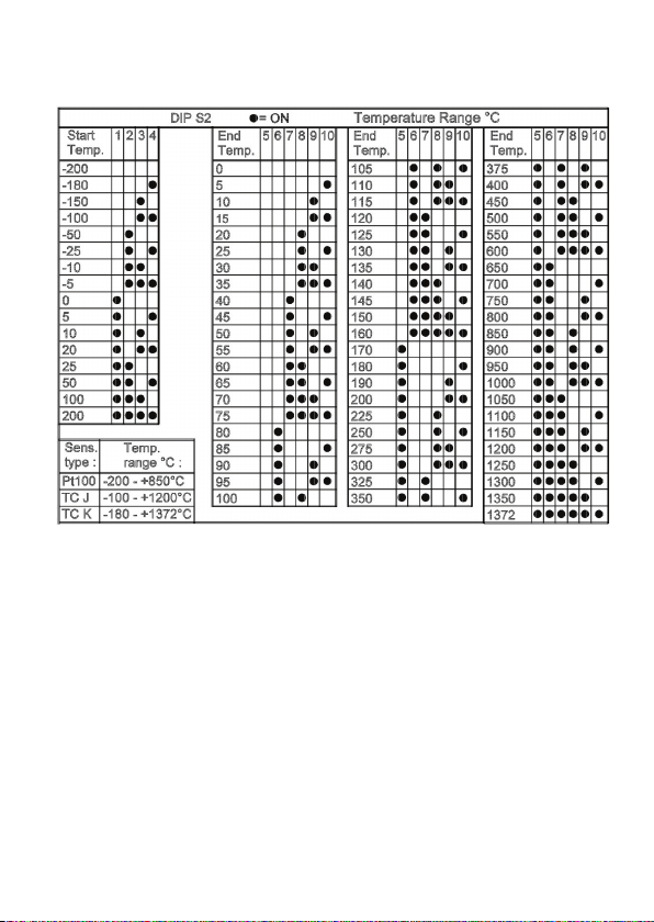
TEMPERATURE RANGE PROGRAMMING
Please note:
a. DRSL-TC and DRSL-TC-ISO - only TC input available
Valid TC J range: -100...+1200°C = correct DIP-switch setting
Valid TC K range: -180...+1372°C = correct DIP-switch setting
b. DRSL-RTD, DRSL-RTD-ISO and DRSL-RTD-LP - only Pt100 input available
Valid Pt100 range: -200...+850 °C = correct DIP-switch setting
c. ”Start temp” must be lower than ”End temp” = correct DIP-switch setting
d. Power must be cycled after DIP-switch positions are changed
14
Page 17

FOR DRSL-TC, DRSL-RTD, DRSL-TC-ISO, AND DRSL-RTD-ISO
FRONT LED INDICATIONS
LED (green) Condition Output Action required
1 flash 0.5 s ON and OFF
Flashing13Hz/15 msON Device OK Energized -
Flashing1Hz/15 msON
Flashing1Hz/500 msON
OFF
Power-up
or Restart
Sensor error
indication
Incorrect DIP-switch
setting
No supply /
device error
De-energized -
Up- or Downscale Check sensor
De-energized
De-energized
Correct setting
and repower
Connect supply /
replace device
15
Page 18
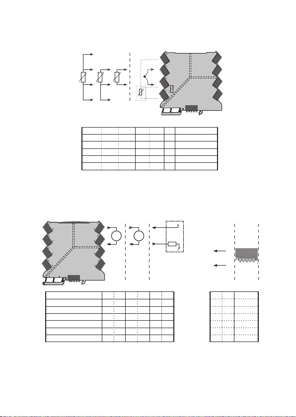
Input wiring
BLOCK DIAGRAM AND WIRING
4
+
3
CJC
2
-
+ -
1
Type
CJC
External CJC
(2- or 3-wire Pt100)
- - - 3 2 Y* DRSL-TC
1,2 & 3,4 1,2 & 3 2 & 3 - - N DRSL-RTD
- - - 3 2 Y DRSL-TC-ISO
1,2 & 3,4 1,2 & 3 2 & 3 - - N DRSL-RTD-ISO
1,2 & 3,4 1,2 & 3 2 & 3 3 2 Y DRSL-TEMP
1,2 & 3,4 1,2 & 3 2 & 3 - - N DRSL-RTD-LP
*DRSL-TC - only internal CJC
Output wiring Supply wiring
+ Vsupply
++ - -
+
+
V
-
4...20 mA
-
+
24 VDC
-
Power
+ -
+ -
rail
+
5
mA
6
-
7
8
DRSL-TC 5 6 5 6 - - 7 8 N
DRSL-RTD 5 6 5 6 - - 7 8 N
DRSL-TC-ISO 5 6 5 6 - - 7 8 Y
DRSL-RTD-ISO 5 6 5 6 - - 7 8 Y
DRSL-TEMP - - - - 5 6 - - N
DRSL-RTD-LP - - - - 5 6 - - N
DRSL-PCU - - - - - - 7 8 Y
DRSL-TC, DRSL-RTD, and DRSL-RTD-LP - no galvanic isolation
DRSL-TEMP - 2 port isolation (reinforced)
DRSL-TC-ISO and DRSL-RTD-ISO - 3 port isolation (reinforced)
16
Page 19

OMEGA ENGINEERING, INC. warrants this unit to be free of defects in materials and workmanship for a period of 13 months from date of purchase. OMEGA’s Warranty adds an additional
one (1) month grace period to the normal one (1) year product warranty to cover handling
and shipping time. This ensures that OMEGA’s customers receive maximum coverage on each
product.
If the unit malfunctions, it must be returned to the factory for evaluation. OMEGA’s Customer
Service Department will issue an Authorized Return (AR) number immediately upon phone or
written request. Upon examination by OMEGA, if the unit is found to be defective, it will be
repaired or replaced at no charge. OMEGA’s WARRANTY does not apply to defects resulting
from any action of the purchaser, including but not limited to mishandling, improper interfacing, operation outside of design limits, improper repair, or unauthorized modification. This
WARRANTY is VOID if the unit shows evidence of having been tampered with or shows evidence
of having been damaged as a result of excessive corrosion; or current, heat, moisture or vibration; improper specification; misapplication; misuse or other operating conditions outside of
OMEGA’s control. Components in which wear is not warranted, include but are not limited to
contact points, fuses, and triacs.
OMEGA is pleased to offer suggestions on the use of its various products. However,
OMEGA neither assumes responsibility for any omissions or errors nor assumes
liability for any damages that result from the use of its products in accordance with
information provided by OMEGA, either verbal or written. OMEGA warrants only
that the parts manufactured by the company will be as specified and free of defects.
OMEGA MAKES NO OTHER WARRANTIES OR REPRESENTATIONS OF ANY KIND
WHATSOEVER, EXPRESSED OR IMPLIED, EXCEPT THAT OF TITLE, AND ALL IMPLIED
WARRANTIES INCLUDING ANY WARRANTY OF MERCHANTABILITY AND FITNESS
FOR A PARTICULAR PURPOSE ARE HEREBY DISCLAIMED. LIMITATION OF LIABILITY:
The remedies of purchaser set forth herein are exclusive, and the total liability of
OMEGA with respect to this order, whether based on contract, warranty, negligence,
indemnification, strict liability or otherwise, shall not exceed the purchase price of
the component upon which liability is based. In no event shall OMEGA be liable for
consequential, incidental or special damages.
CONDITIONS: Equipment sold by OMEGA is not intended to be used, nor shall it be used: (1) as
a “Basic Component” under 10 CFR 21 (NRC), used in or with any nuclear installation or activity;
or (2) in medical applications or used on humans. Should any Product(s) be used in or with any
nuclear installation or activity, medical application, used on humans, or misused in any way,
OMEGA assumes no responsibility as set forth in our basic WARRANTY/ DISCLAIMER language,
and, additionally, purchaser will indemnify OMEGA and hold OMEGA harmless from any liability
or damage whatsoever arising out of the use of the Product(s) in such a manner.
WARRANTY/ DISCLAIMER
Direct all warranty and repair requests/inquiries to the OMEGA Customer Service Department.
BEFORE RETURNING ANY PRODUCT(S) TO OMEGA, PURCHASER MUST OBTAIN AN
AUTHORIZED RETURN (AR) NUMBER FROM OMEGA’S CUSTOMER SERVICE DEPARTMENT
(IN ORDER TO AVOID PROCESSING DELAYS). The assigned AR number should then be marked
on the outside of the return package and on any correspondence. The purchaser is responsible for
shipping charges, freight, insurance and proper packaging to prevent breakage in transit.
FOR WARRANTY RETURNS, please have
the following information available BEFORE
contacting OMEGA:
1. Purchase Order number under which the
product was PURCHASED,
2. Model and serial number of the product under
warranty, and
3. Repair instructions and/or specific problems
relative to the product.
OMEGA’s policy is to make running changes, not model changes, whenever an improvement is
possible. This affords our customers the latest in technology and engineering.
OMEGA is a registered trademark of OMEGA ENGINEERING, INC.
© Copyright 2014 OMEGA ENGINEERING, INC. All rights reserved. This document may not be copied,
photocopied, reproduced, translated, or reduced to any electronic medium or machine-readable form,
in whole or in part, without the prior written consent of OMEGA ENGINEERING, INC.
RETURN REQUESTS/ INQUIRIES
FOR NON-WARRANTY REPAIRS,
OMEGA for current repair charges. Have
the following information available BEFORE
contacting OMEGA:
1. Purchase Order number to cover the COST
of the repair,
2. Model and serial number of the product, and
3. Repair instructions and/or specific problems
relative to the product.
consult
Page 20

Where Do I Find Everything I Need for
Process Measurement and Control?
OMEGA…Of Course!
Shop online at omega.com
SM
TEMPERATURE
MU
Thermocouple, RTD & Thermistor
Probes, Connectors, Panels &
Assemblies
MU
Wire: Thermocouple, RTD &
Thermistor
MU
Calibrators & Ice Point References
MU
Recorders, Controllers & Process
Monitors
MU
Infrared Pyrometers
PRESSURE, STRAIN AND
FORCE
MU
Transducers & Strain Gages
MU
Load Cells & Pressure Gages
MU
Displacement Transducers
MU
Instrumentation & Accessories
FLOW/LEVEL
MU
Rotameters, Gas Mass Flowmeters
& Flow Computers
MU
Air Velocity Indicators
MU
Turbine/Paddlewheel Systems
MU
Totalizers & Batch Controllers
pH/CONDUCTIVITY
MU
pH Electrodes, Testers &
Accessories
MU
Benchtop/Laboratory Meters
MU
Controllers, Calibrators, Simulators
& Pumps
MU
Industrial pH & Conductivity
Equipment
DATA ACQUISITION
MU
Data Acquisition & Engineering
Software
MU
Communications-Based
Acquisition Systems
MU
Plug-in Cards for Apple, IBM &
Compatibles
MU
Data Logging Systems
MU
Recorders, Printers & Plotters
HEATERS
MU
Heating Cable
MU
Cartridge & Strip Heaters
MU
Immersion & Band Heaters
MU
Flexible Heaters
MU
Laboratory Heaters
ENVIRONMENTAL
MONITORING AND CONTROL
MU
Metering & Control
Instrumentation
MU
Refractometers
MU
Pumps & Tubing
MU
Air, Soil & Water Monitors
MU
Industrial Water & Wastewater
Treatment
MU
pH, Conductivity & Dissolved
Oxygen Instruments
M5399/0614
 Loading...