

Page 1
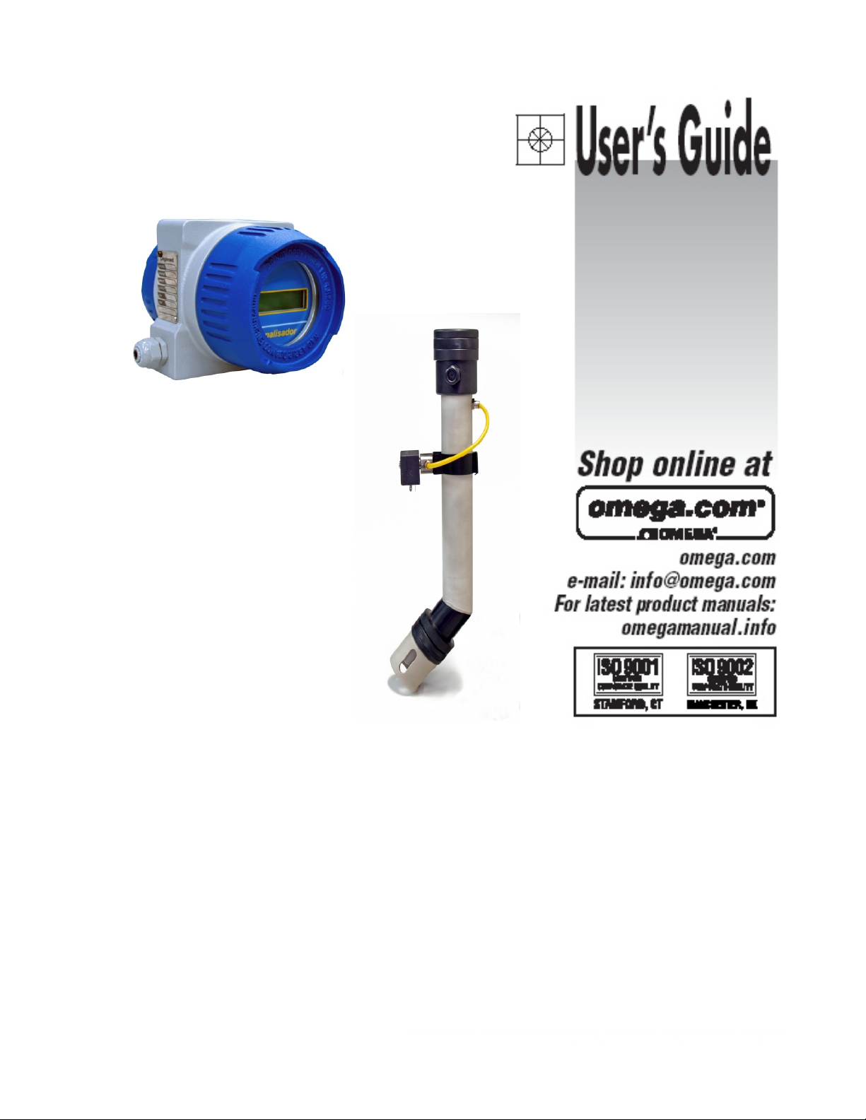
DOTX441
Dissolved Oxygen Analyzer
Page 2
Page 3
Instruction Manual
Dissolved Oxygen Analyzer
DOTX441
Index
Specifications..........................................................3
Mechanical Description..................................................4
Typical Installation......................................................5
Equipment Installation...................................................6
Electrical Schematics ...................................................9
Equipment Operation...................................................10
Equipment Operation DO - Set Up ........................................13
Equipment Operation DO - Calibration.....................................21
Equipment Operation DO - Read .........................................22
Maintenance .........................................................23
Cell Maintenance......................................................24
Protocol Communication................................................29
Page 4

2.
Application
Analyzer/Tansmiter/Dissolved Oxygen
Controler Micro processed
GENERAL
Case Cast Aluminum SAE 323
Finishing Electrostatic Epoxy Paint
Electrical Connection Connector Barr – Conexell Type
Cable Inlet Cable Knockout 1/2" ( 2 x )
Assembly 2" Tube or Flat Surface
Identification (TAG) SS Tag
Enclosure IP-68
Power Consumption 3.5 VA
Weight 1.9 Kg
Electrical Power 90 to 240 VAC ( 50 / 60 Hz)
Working Temperature 5 to 40ºC
Relative Humidity 20 to 80 %
Analyzer / Transmiter
Display Alphanumeric 2 lines x 16 characters
Range 0 to 60 mgO2/L
Resolution 0.1 or 0.01
Relative Precision 0.02 % (full scale)
Working Temperature 50 ºC
Auto Temperature Compensation 50 ºC
Measuring Princíple Clark Polarographic Cell
Response Time 20 s (Programmable)
Barometric Pressure Compensation Up to 10.000 m
Signal Output
Analogic 4 to 20 mA w/ programmable output range
for all Reading range
Galvanic Isolation 2000 VAC ( by opto coupler )
Line Resistance 1K3 Ohms
Controller
Actuation Type Frequency Modulation, P+Di
Set-Points 2 independent from 0 to 100% of scale
Outputs 2 control ON-OFF, programmable for Alarm or
Actuation P+Di
Control for Automatic Cleaning Timer ON-OFF, for periods up to 99 seconds, and
in intervals up to 99 hours
Cell Model: DOE-441
Type Immersion
Body Material Polypropylene (PP) or SS 316(others upon request)
Maximum Temperature (@ Atm. Press.) 50 ºC
Body Length 1500 mm (standard, others upon request)
Auto Cleaning System Activated by a solenoid valve
Accessories
Instruction Manual on a CD
SS 304 clamps with nuts and bolds
Specificatons
3
Page 5
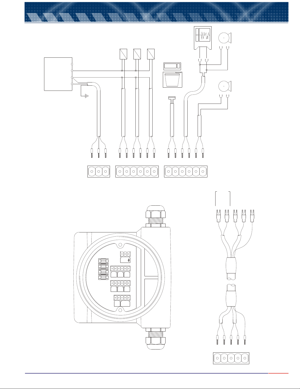
3.
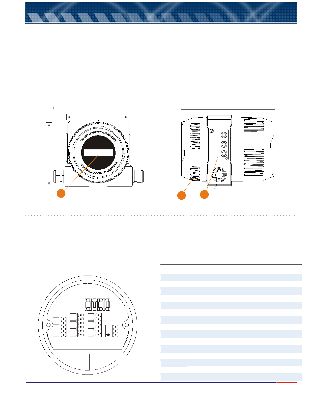
Slots Connections
1 Dissolved Oxygen Cell Shield
2 & 3
Measuring Sensor
4 & 5
Thermocompensator
6 & 7
Transmission Output mA - 1
8 & 9
Transmission Output mA - 2
10 & 11
Digital Output Communication RS - 485
12 & 13
Set-Point 3 ( S3 ) Contacts – Auto Cleaning
14 & 15
Set-Point 2 ( S2 ) Contacts
16 & 17
Set-Point 1 ( S1 ) Contacts
18
Grounding
19 & 20
Electrical Power from 90 thru 240 VAC 50 / 60 Hz
F1
General Fuse (3 A )
F2
Set-Point 1 Fuse (1 A )
F3 Set- Point 2 Fuse (1 A )
F4 Set- Point 3 Fuse (1 A )
Mechanical Description
The equipment is offered in compact case in cast aluminum. SAE 323, with low oxidation grade, with anti
corrosion treatment and finished with electrostatic epoxy paint. Reduced dimensions and very light weight, it is
build under IP-68 protection.
User will find under the same case: the local indicator, Analyzer, Transmitter, Controller and the Register, making
the equipment compact , rough and of ease operation.
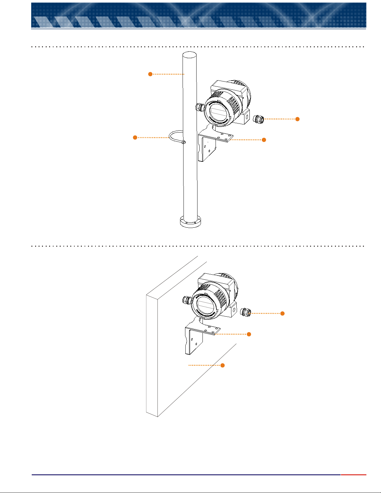
The case installation can be done in 2” tube or Flat Surface.
Electrical connection is done by a terminal barr located in the case’s back housing of the instrument, with cable
Entrance thru 2 cable press of ½ ” BSP.
In one the instrument sides, user will find an identification tag in SS 316, which covers the external controls, sealed in
Order to guarantee the case protection.
190
126
180
125
1
Items Description
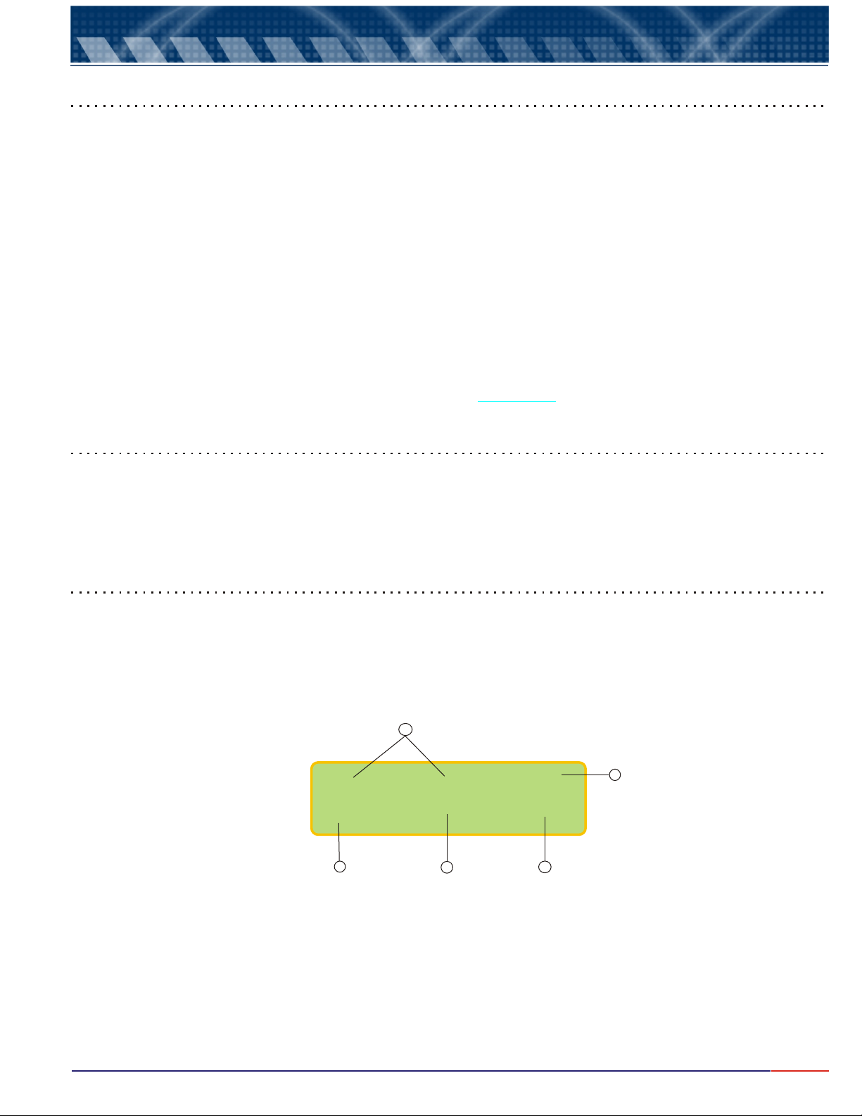
1 - Display: Alphanumeric back lighted 2 Lines x 16 characters
2 - Keyboard: 3 keys
key Select the desired function, flashing option.
key Confirms the selection chosen by Select key.
key .
3 - Insterconnection Board (located inside the back lid)
<SEL>
<ENT>
<ESC> returns to prior menu
DOTX441DOTX441
THERMO
5
Gre
Yel
4
3
Black
2
Red
..
Shie
1
CN1
F4F4
RS485
++
11
- - ++
10
9
mA-2
- - ++ - -
8
7
mA-1
6
F3F3
F2F2 F1F1
No
S1
C
No
S2
C
No
S3
C
CN3CN2 CN4
SEL.
TAG
ENT.
ESC.
2 x Æ ½" BSP 14 tpi
3
*Dimensions in millimeters
17
16
15
14
13
12
20
AC
19
18
2
4
Page 6
4.
Typical Installation
2” Tube Installation
2” Tube
Cable Knockout
Clamp (SS)
Flat Surface Installation
Support base (aluminum SAE 323)
Cable Knockout
Support base (aluminum SAE 323)
Flat Surface
Important: Install the equipment in a strategic location that allows ease access and maintenance and avoid
exposing it direct to solar rays, besides equipment’s overheating causing eventual damage, the Liquid Crystal
Display will also loose it’s sensibility, fading the display.
5
Page 7
5.
Equipment Installation
In order to achieve the best performance of OMEGA’s Continuous Analyzer, it is crucial to perform it’s correct
installation. Follow instructions below:
1. Remove the equipment from the box, verify if any damage was caused by it’s transportation.
2. Install the case in a strategical location, for ease access and maintenance, exempt of vibrations and vapors.
3. Avoid exposing the equipment direct to solar rays. If necessary use some kind of protection.
4. After connecting the cable with it’s respective terminals, proceed with terminal barr connection, located in
the back panel of the case.
5. Inspect all electrical installation in order to certify that all connections are correct.
6. Verify power electrical source in order to make sure it’s voltage value.
7. Turn on circuit breakers of the electrical box.
5.1 Important Recommendations
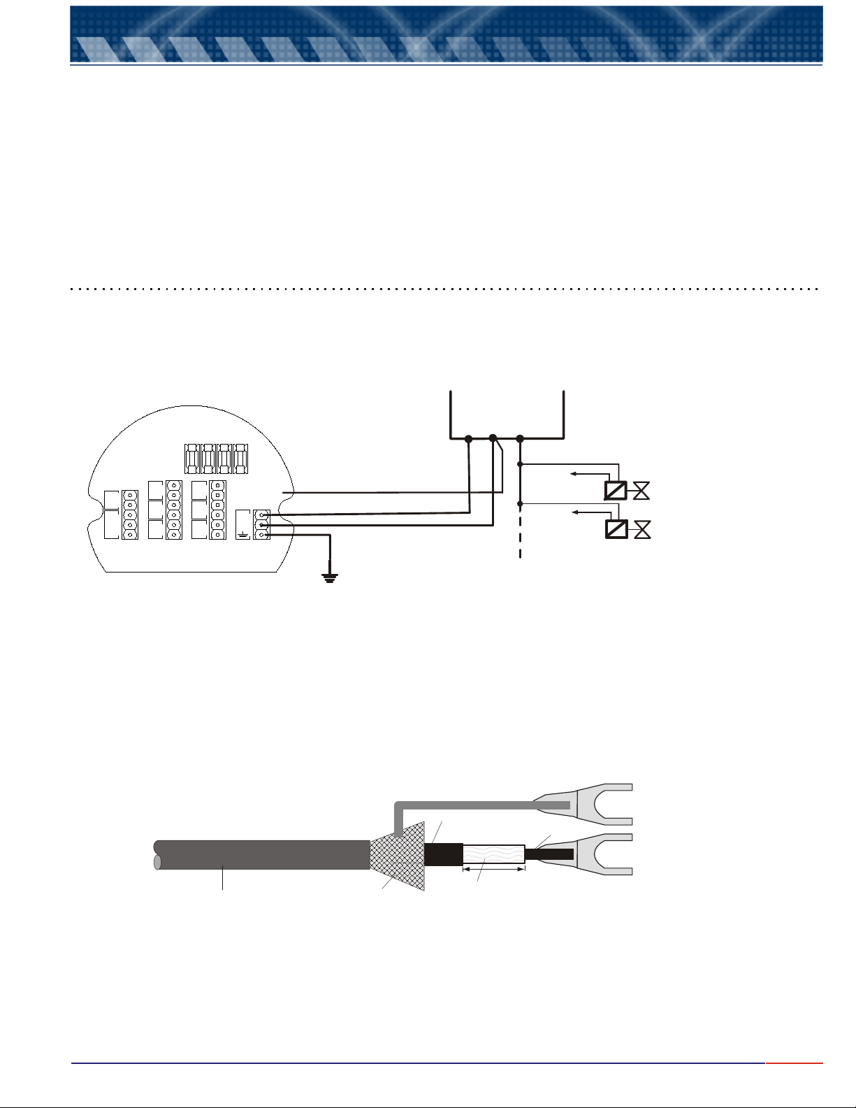
1 - The equipment electrical power must be independent from others system components. Being so, the cable
that will power the Control Valves, Solenoids, Alarms, and others, MUST BE CONNECTED DIRECT TO
DISTRIBUTION BOX, and "never" to the equipment slots.
Distribution Box
F3
F2 F1
DOTX441DOTX441
TO-401
THERMO
5
Gre
Yel
4
3
Black
2
Red
.
Shie
1
CN1
F4
20
AC
19
18
To Contacts NO
RS485
+
11
- +
10
9
mA-2
- + -
8
7
mA-1
6
No
S1
C
No
S2
C
No
S3
C
CN3CN2 CN4
17
16
15
14
13
12
13,15 & 17
R S T N
12
14
Controls or Alarms
Grounding
2 - Verify if the cable knockouts of the equipment and probes are firmly attached to its respective
interconnection cable. This proceeding is necessary in order to preserve IP-68 protection.
3 - Be careful with humidity!. It will diminish the impedance generating measurement errors. Verify the
cable knockouts and if necessary, dry them using a hair dryer.
4 - Replace periodically the sealing O-Rings in order to guarantee a good sealing of the enclosure.
5 - Do not cut or mend the interconnection cables. Under the cable shield there is a semiconductor coating
material, used to eliminate electrostatic interference at the cable.
Semiconductor
Cap
Conductor
d
Covering
6 - ON-OFF are , offering innumerous advantages for the equipment, such as: no
outputs thyristor type
Shield
Isolation (polypropylene)
d = 5 mm
min
sparks presence, faster commutation, noise practically inexistent, no presence of RF interference and many
more.
The outputs can commute any charge, since they are
powered by alternate tension (VAC).
6
Page 8
5.
Equipment Installation (cont.)
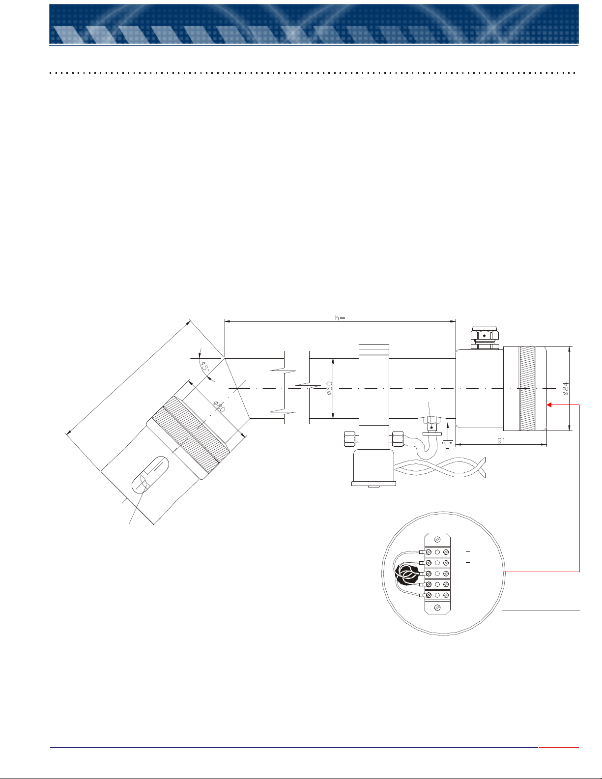
5.2 Dissolved Oxygen Industrial probe Characteristics - DOE-441
Dissolved Oxygen Immersion Probes for industrial application, consists typically in an adequate installation
hardware, whose function is to hold and protect the Dissolved Oxygen industrial cell model: and ti’s
respective connections.
In order to choose the adequate material to it’s body construction will depend on work’s chemical aggressiveness
and temperature of the process. Find below some materials available:
a) PP (Polypropylene) - Model DOE-441 (Standard)
b) Stainless Steel 316 - Model DOE-441-S (Special Order) and others upon request.
All connections offer guaranteed sealing by Nitrilic Rubber O-Rings, FKM or others. The electrical connection is
done thru a terminal barr in an IP-68 case protection, with cables going thru a ½” NPT hole or ½” cable pres and the
interconnection of the Probe’s terminal barr to the cell being done by PA type connector. It is recommended that the
connection cable from the probe to the equipment offers the shortest length possible, in order to avoid RF
interference and noise problems.
The installation of the Probe can be done by a pole or flange and the insertion length is defined based on the need of
measure to be taken, being supplied with standard of h=1500 mm.
DOE-441-R
Cleaning Injector Tip
1500
Quick Connect
NTCNTC
NTCNTC
AnodeAnode
CathodeCathode
ShieldShield
Analyzer (8)
Distribution Box (T)
(Green)
(Yellow)
(Red)
(Black)
Interconnection BarrInterconnection Barr
Located internally
at the Electrical
Connection Box
7
Page 9
5.
Equipment Installation (cont.)
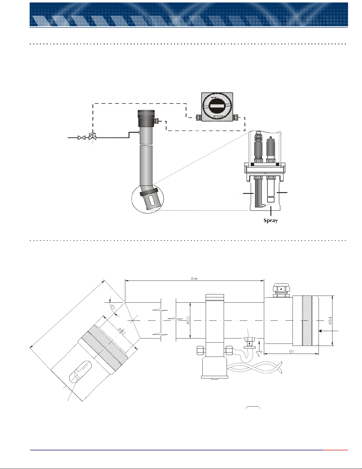
5.3 Automatic Cleaning System hose installation
Probes DOE-441, are supplied with Automatic Cleaning System, whose function is to remove any clogging at the
membrane of the Dissolved Oxygen’s Cell. Typically, the cleaning is done by pressurized air jet (3 bar maximum).
The cleaning is executed a solenoid valve activation controlled by the equipment. The time and duration of the
cleaning can be programmed, by accessing the Set Up operation of the equipment’s program.
At slots 12 & 13, there is a thyristor contact (S3) that commands the Solenoid for the cleaning system.
Automatic Timer
DO Signal
Cleaning Solution
or Air
Solenoid Valve
DOTX441
Injector Tip
DO Cell
ø1/4” x 1/8” Parker U-42 Hose Installation
Insert the hose at the connection (quick connect) all the way down. Metal holdings located inside of the ring will
attach and hold the hose, push the ring following the same direction as arrow “L” shown on below illustration.
Never pull the hose, as it will damage the metal clips.
1500
Quick Connect
Analyzer (8)
Distribution Box (T)
Cleaning Injector Tip
Important:
When noticed a drop in sensibility during calibration, frequently deviations of calibrated value or even reading
oscillations, it is necessary to proceed with a cell maintenance. The steps in order to perform this operation, you will
find on chapter 12 - Cell Maintenance, page:22.
8
Page 10
6.
Electrical Installation
CONTRÔLOrALARMS
16
TT NN
ELECTRICAL
SS
DISTRIBUTION
BOX
1919
RR
2020
1818
17
15
AUTOMATIC
14
13
2
CLEANING
GRÁPHIC REGISTER
OR PLC OR SDLC
PUMP
12
PCPC
1
PUMP
GROUNDINGGROUNDING
CABLECABLE
33
2020
1919
Note: Note:
It is important to use phase and cables
different for the equipment and
control valves or alarms.
CABLECABLE
44
CABLE CABLE
55
1818
1717
1616
1515
1414
CONVERTERCONVERTER
RS-485 RS-485
/ /
CABLECABLE
66
1313
1212
RS-232RS-232
CABLECABLE
88
CABOLECABOLE
77
1111
1010
CABLECABLE
99
99
88
77
66
CN2CN2 CN3CN3 CN4CN4
NTCNTC
GreenGreen
YellowYellow
Black Black
Red Red
(Anode)(Anode)
(Cathode)(Cathode)
ShieldShield
CELLCELL
2020
1818
1919
ACAC
1717
1414
1212
1313
1515
F2F2 F1F1
F3F3
F4F4
1616
CN3CN3CN2CN2 CN4CN4
S2S2
S3S3
S1S1
CC
1010
-- ++
55
TERMOTERMO
GrGr
NoNoCCNoNo
99
mA-2mA-2
44
YelYel
886677
-- ++ --
33
PblaPbla
CC
mA-1mA-1
11
22
CN1CN1
..
RedRed
ShieldShield
NoNo
1111
++
RS485RS485
DOTX441DOTX441
22
CABLECABLE
INTERCONNECTION
CABLE
BlackBlack
Green.Green.
YellowYellow
44
55
11
CABLECABLE
RedRed
ShieldShield
221133
EQUIPMENTEQUIPMENT
CN1CN1
9
Page 11

7.
Equipment Operation
Important Information
1 - Never forget that if the instrument is turned off, it is necessary to wait for the cell polarization (aprox. 12 min.).
2 - While at , is possible to obtain other information, such as:
By pressing , user can obtain the Temperature value, or the Set - Points, programmed during
mode.
By pressing , it moves the equipment to STAND BY . While in STAND BY the outputs will be turned
off, that means, the current output goes to 4 mA and the contacts to NO. The outputs must be programmed by the
user.
<ESC>
3 - . This time is necessary in order to certify
that the user desires to exit the selected option.
4 - During certain program steps, it is allowed to adjust such values as: Span, salinity, barometric pressure, set-points,
hystereses and others. The adjust is done by indication of arrows (decrease) and (increase).
order to choose the correct option, increase “>” or decrease “<” then confirm by pressing
Press
5 - When power failure occurs, when the equipment turns back on the initial pre-programmed conditions will remain as
prior to the power failure. Wait for the Cell Polarization. If the equipment is under , it will return to
Reading and no further action will be necessary!
While at Stand By, if a power failure occurs the instrument will not return to reading mode after the polarization is
completed, it will go to the main menu (select Function).
READ
key is only recognized when pressed and hold for about 5seconds
<SEL>
<SEL>
<ENT>
key again until user reaches the desired value, then press key to confirm.
mode
key
key mode
SET UP
< > Press key in
<ENT>
<ENT>
READ
mode
<SEL>
key.
6 -Syntonizing P + Di Contol
The Period Value (Di), must be established in relation to the retention time of the process.
Example: Retention Time is equal 30 minutes, establish a period of 1 minute.
The Proportional Band (BP), must be equally established in relation to the reagent concentration and of the process
homogenizing power. Start with 50 % of PB and increase or decrease it in relation to its variable response.
10
Page 12
7.
Equipment Operation (cont.)
Set Up Procedures
The Equipment offers a non-volatil memory (E2PROM) in order to store operation’s functions (Resolution,
Reading Mode, Calibration, etc) . Even when turned off from power, all functions chosen during set up will
remain stored. Before you start any work with the equipment, it is recommended to verify the
conditions
Press and hold key until reached the Select Function Menu. When at the
menu
order to access the , press key until SET UP flashes, then press
confirm the option
and follow step by step the options shown at the display. In case the user desires to switch the flashing
option, press key and change as needed following the display commands, then
to confirm the option chosen.
When a mistake is made and the user needs to go back to change it, press . The display will
move back one screen at a time for every option.
At the flow chart, the flashing option will be displayed in
, to certify that you have chosen the correct options fro your work and to avoid operation errors.
<ESCAPE>
, press key in order to select the function desired, flashing option, then press In
<SELECT>
SET UP
. A Password will be requested, press in sequence ( , , )
<SELECT>
menu key to
<SELECT>
<SELECT>
Blue Color
.
SELECT FUNCTION
<ENTER>
<ESCAPE>
SET UP
<ENTER>
<ENTER>
<ESCAPE>
<ENTER>
Check Operation
.
key
The option Sensor is very useful, as it allows the user to verify the cell condition. This option is self
explanatory, just press key until Check flashes, then press .
Then follow the display instructions as it sel explanatory.
CHECK
<SELECT> <ENTER> key to confirm the option
Read Operation
At this operation user will have options to or . In case the desire is to the Cell, press
<SELECT> option flashes key to confirm it
program will guide the user step by step on how to proceed with a perfect calibration. In case the desire is to ,
press place the cell at the sample and press
show the following format
key in until , then press . From this point on the
<ENTER> <ENTER>
CALIBRATE
key at flashing option Read then , the display will then
:
CALIBRATE READ CALIBRATE
<ENTER>
5
4
READ
»»» »»»» »»»
-> »»»»»»» @ »»»»
1
2
3
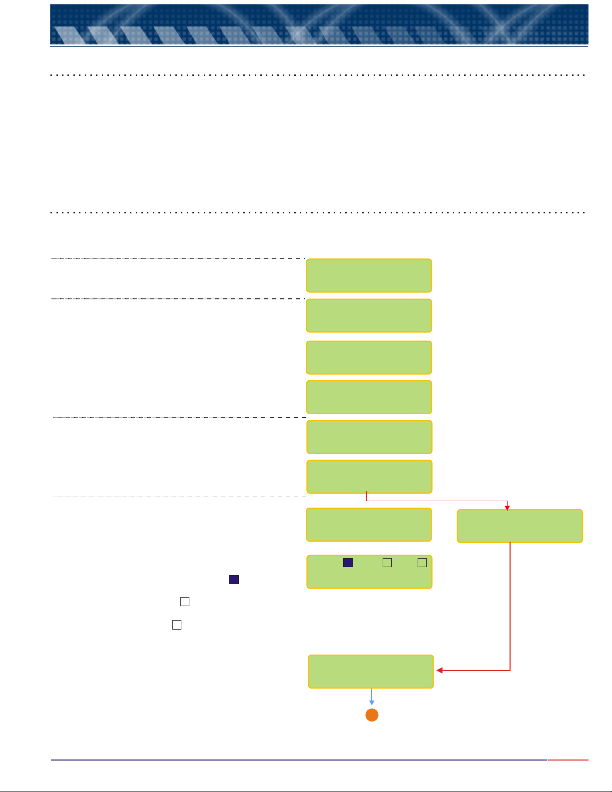
1 - The "Prompt" is a signal that will flash at every executed reading or depending on the Time between
Readings, chosen during Set Up Mode.
2 - The measured value
3 - Reference Temperature
4 - Sample Temperature
5 - Set - Points S1 & S2 conditions
Note: while indicating the set-points, the sample temperature (4) will not be displayed.
11
Page 13
Operação do equipamento
4.
7.
Equipment Operation (cont.)
Basic Operations
Menus are self explanatory and of ease interaction. In order to input or alter data, menus are offered always as
flashing option and in order to choose this option, press key, than press
option chosen <ESCAPE>
the program will move back one step at a time), except while at Reading Mode, when this key needs to be pressed
and held for about 5 seconds in order to exit the Reading Mode.
The equipment stores all configurations at a non-volatile memory. Even when turned off, the conditions will
remain stored.
. key is used to change option or correct data chosen at prior screens (at every touch,
<SELECT> <ENTER> to confirm the
Turning On the equipment
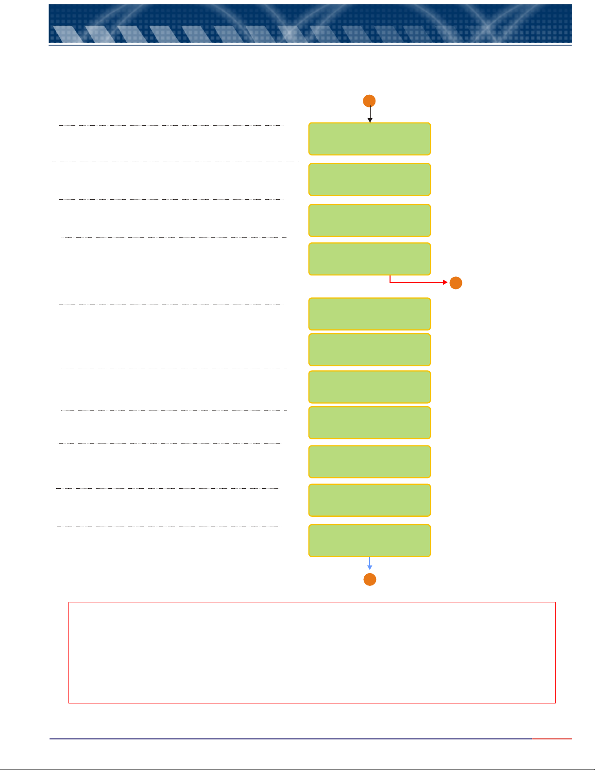
1 - Power the Equipment. The display will show the following menus as described below.
Indicates the model and firmware version of the
equipment
Software will perform an auto check of the memories
and also of the display
Cell will be Polarized and this process should take 12
minutes to complete.
After the Polarization is completed, the instrument will
perform the Reading operation and in order to exit and
access the Main Menu, where user will be able to Set
Up the instrument, press and hold for about 5 seconds
<ESCAPE> key.
Interpreting the Read menu. For S1, the indicates
that this contact was set as On during Set Up and it
is now operating. For S2, the indicates that this
contact was set as On during Set Up but it is not
operating now. For S3, the indicates that this
Contact was set to Off during Set Up.
X
OMEGA
DOTX441 V1.1
AUTO CHECK
DISPLAY TEST
»»»»»»»»»»»»»»»»
»»»»»»»»»»»»»»»»
WAIT IN
POLARIZATION
11min : 59 sec
IN POLARIZATION
S1:» S2:» S3:»
-> 49.98ppm
S1: S2: S3:
-> 49.98ppm
Indicates when the
Bargraph was chosen
during Set Up Mode.
================
-> 49.98ppm
X
<ESCAPE>
DISSOLVED OXYGEN
/SET UPREAD
A
Go to Page 13
12
Page 14
7.
Equipment Operation DO - Set Up
Before starting a new operation, make sure that the Set Up conditions are correct for the application being
performed.
From Page 12
A
Press until flashes then press <SEL> Set Up <ENT>
A Password is required in order to access the .
Press in sequence , and keys.
In order to select the desired language, press
key until the desired option flashes, then press
key to confirm .
User can program the instrument, such as Calibration
Default,
Resolution, on line Calibration and more. If chosen ,
the last configuration will remain in effect. Press
<SEL>
<ENT>
You can calibrate the instrument as factory default.
Choose and confirm and the instrument will
calibrate as factory default! This option is offered in
case the user does have any other way to perform a
calibration procedure.
The user will be allowed to chose the unit desired.
Press until the desired option flashes then
confirm by presssing .
key until the desired option flashes, then press
key to confirm .
Yes
<SEL>
<SEL> <ENT> <ESC>
<ENT>
SET UP
<SEL>
<ENT>
No
DISSOLVED OXYGEN
READ/SET UP
PASSWORD
___
LANGUAGE: /
PORT
ENGLISH/SPANISH
CONFIG INSTR.?
/ YES NO
B
CAL. DEFAULT?
/ YES NO
CONFIRM?
/ YES NO
UNIT:
/ mg/LPPM
Go to Page15
The Range cannot be changed. It is default from factory.
The Resolution can be chosen, by pressing
key until the desired opiton flashes and confirmed by
pressing
The user will be allowed to adjust the DO value read at
sample. Press until flashes then confirm
by presssing .
<ENT>
<SEL> MAN
<ENT>
User has the option to choose the Calibration type
desired. Press key until the desired option
flashes, then press key to confirm the option
chosen. If air, calibrate the cell dry at 2cm from water
surface, and if water, dip the cell into Saturated
distilled water with Oxygen. See page 19.
Note A: Every time you see the symbols “ ” “ ”, that means that the user can adjust the displayed
value up or down.
To increase the value pres key until “ ” flashes, then press to confirm, then press
key and at every touch the value will increase by one unit.
To decrease the value press key until “ ” flashes, then press to confirm, then press
key and at every touch the value will decrease by one unit.
If a mistake is made, press key to return and correct the value!
<SELECT>
<ENTER>
<SEL> <SEL>
<SEL> <SEL>
<ESC>
<SEL>
and <
>
>
<
0 to 60 PPM
RESOLUTION
1 / 0.1 / 0.01
ON-LINE CAL,
/ YES NO
CALIBRATE IN:
/ WATERAIR
A
Go to Page 14
<ENT>
<ENT>
RANGE
13
Page 15
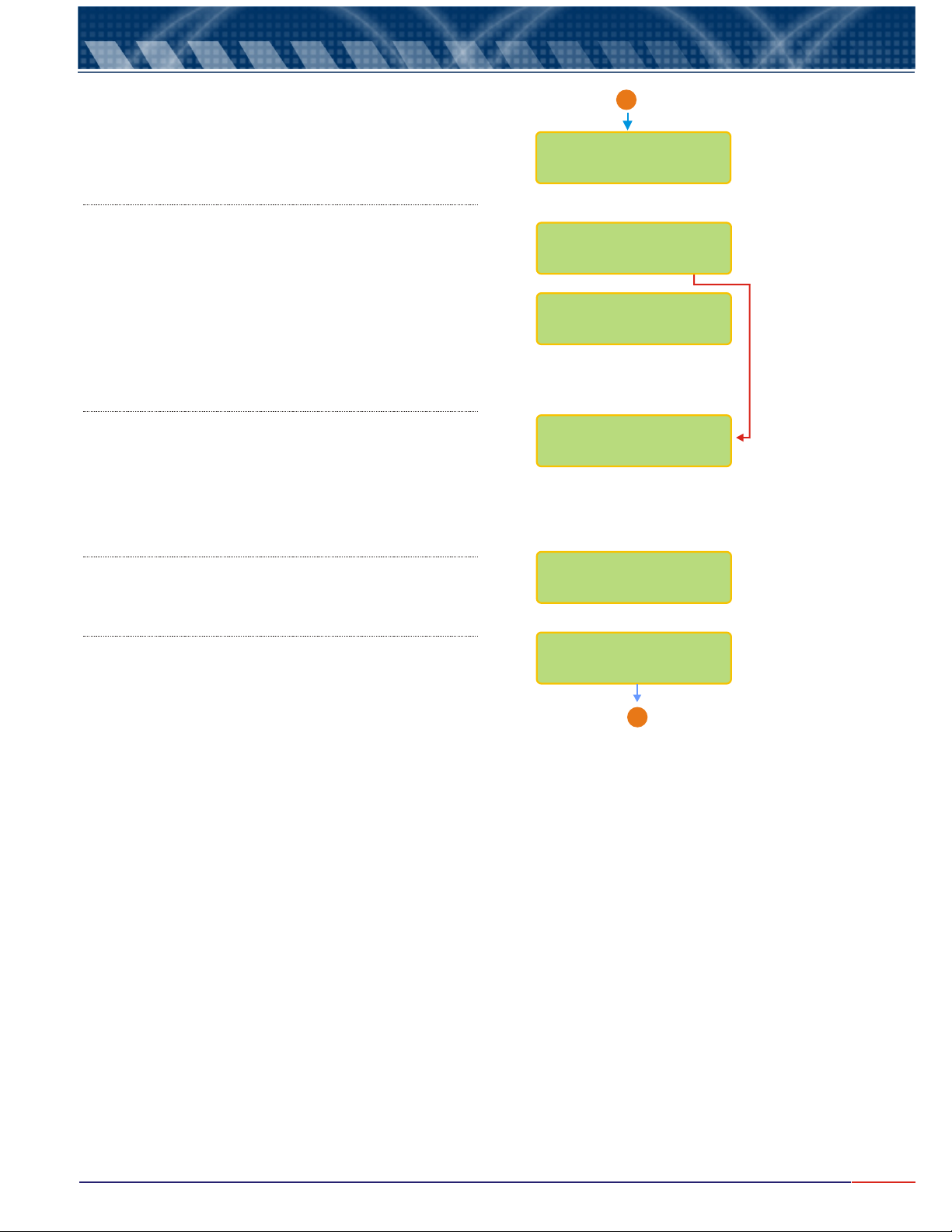
7.
Equipment Operation DO - Set Up (cont.)
User has the option to choose the Zero calibration type
desired. Press key until the desired option
flashes, then press key to confirm the option
chosen. If Zero Auto - Zero is achieved internally by the
instrument. If Zero Manual - also known as Zero Chemical,
use solution without Oxygen presence.
Span is the second calibration point and user has the
option to choose between Span Manual - when user has
a solution with a known dissolved oxygen value,
obtained thru Winkler Method, so read values can be
compared to the Winkler values or Span Auto automatic conditions, with atmospheric air. Press
<SELECT>
<ENTER>
press key to confirm the option chosen.
The Span Resolution will depend upon the Resolution
chosen for Reading. Refer to page 13 (Note A) for
instructions on how to adjust this value.
User can adjust the Salinity value, so the salinity
compensation can be performed. So the salt concentration
of the sample, needs to be known. Remember that at fresh
water this value does not exceed 2000µOhms/cm, that
corresponds to 1000ppmwhere use can considres the
adjust to 0 (zero). Refer to page 13 (Note A) for instruction
on how to adjust this value.
<SELECT>
<ENTER>
key until the desired option flashes, then
From Page 13
A
ZERO
/ AUTOMANUAL
SPAN:
/ MANUAL AUTO
SPAN:
7.50 ppm <>
SALINITY
0 ppm <>
User can adjust the Barometric Pressure Altitude. Up to
4500meters. Find out the Barometric Pressure Altitude
of the location where the instrument will be used and refer
to page 13 (Note A)for instruction on how to adjust this value.
User can adjust the Temperature Coefficience. This is used
to correct the variation imposed by the Cell Membrane.
A membrane of 50 mµ has a Temperature Coefficiency of
4.10% / °C. In case thinner or thicker membranes are used,
the correct value, must be used. Refer to page 13 (Note A)
for instruction on how to adjust.
BAROMETRIC PRES.
ALTITUDE:800m <>
TEMP; COEF.
4.10% / ºC <>
A
Go to Page 15
14
Page 16
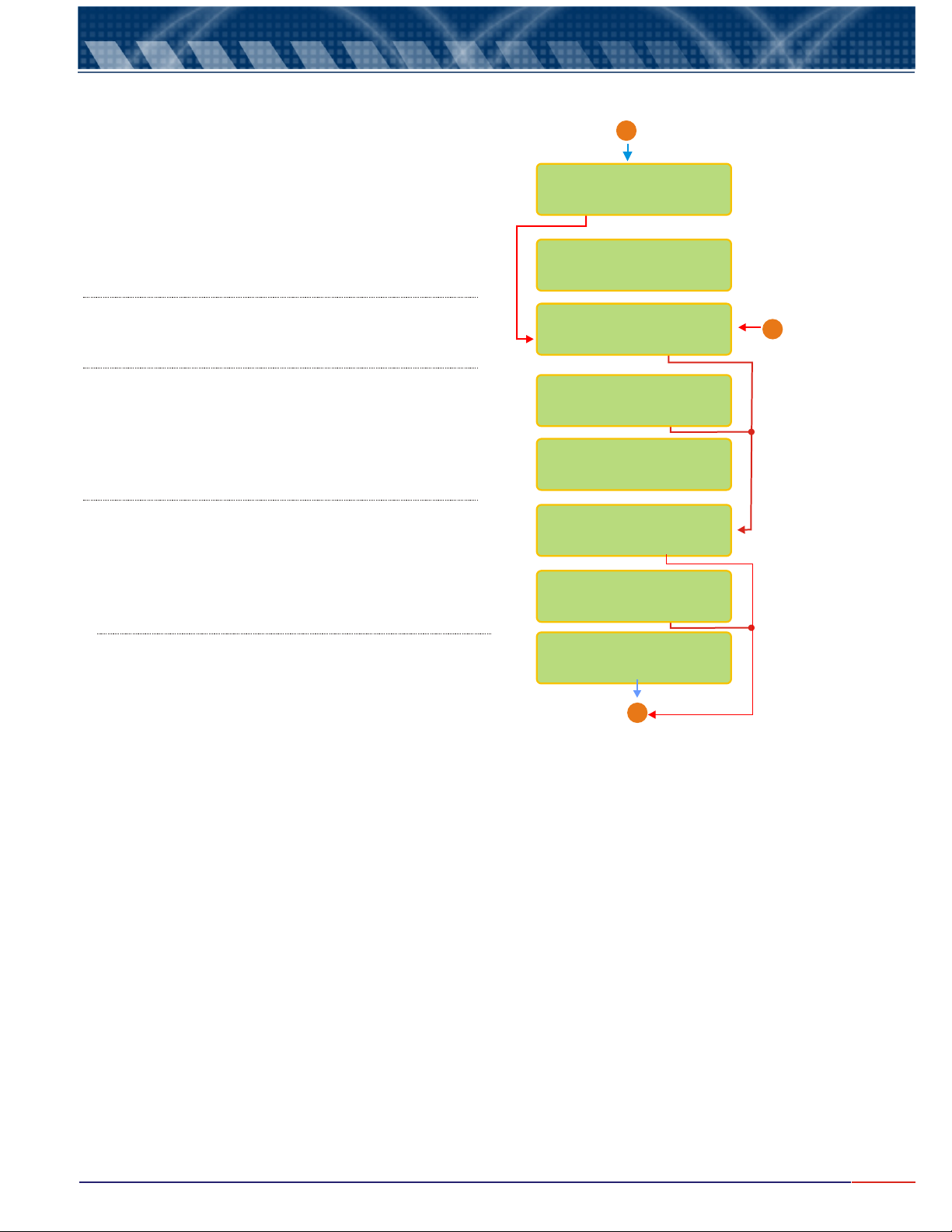
7.
Equipment Operation DO - Set Up (cont.)
From Page 14
A
User can choose between the following Reading Modes:
Continuous - Read continuously after time is set
Average - Reads the average after time is set
Hold - user must press key to Read
User can program the time between Readings.
Refer to Page 13 (Note A) for instructions on how to
adjust this time.
User can program the display to show information like
Barr graph, Clock and more.
User can choose if desire to have Barr graph shown
above the Reading screen. When Bar Graph is
displayed, the information about Sensibility and Sample
Temperature will not be displayed!
User can now adjust the Minimum and Maximum
values for the Bar Graph. Refer to Page 13 (Note A)
for instructions on how to adjust this value.
User can choose to display the clock when sending
data information thru RS-485.
User can adjust date and clock, if desired.
<ENTER>
READING MODE:
/CONTIN. AVER.
TIME BETWEEN
READINGS: 5s <>
DISPLAY?
/ YES NO
BARGRAPH?
/ YES NO
>
Min.:0ppm
Max.:60ppm
<
<
>
CLOCK?
/ YES NO
ADJUST CLOCK/
/ YES NO
From Page 13
B
<SELECT>
Use key to change numbers and when
finished, press key. If a mistake is made,
<ESCAPE>
press key to move back.
<ENTER>
14/03/2007
11:20:00
A
Go to Page 16
15
Page 17
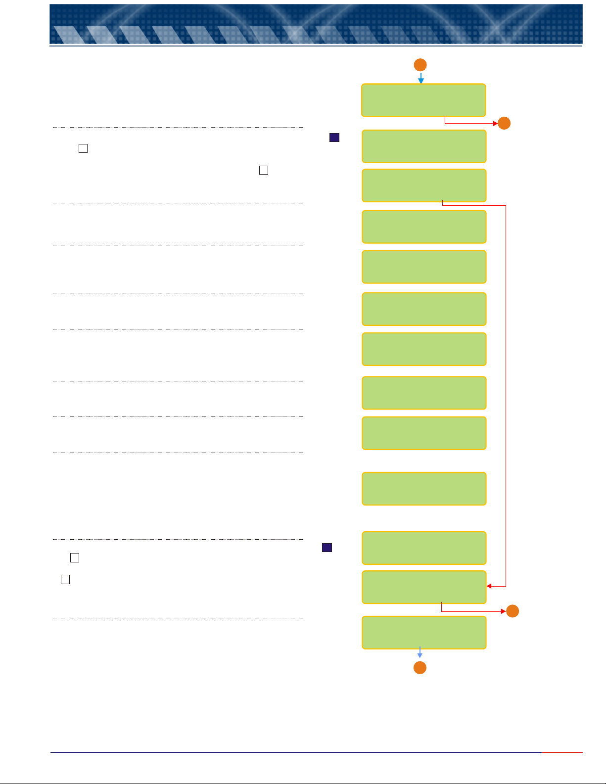
7.
Equipment Operation DO - Set Up (cont.)
From Page 15
A
User has the option to configure Contacts SP 1, SP 2 and SP 3
Press key to choose the desired option then
<SELECT>
press key to confirm.
<ENTER>
If user chooses Contact S1 as On, while at Reading Mode, a
or a will be displayed after the S1, indicating that this Contact
is On. If user chooses
Contact S1 as Off, while at Reading Mode, a will be displayed
after the S1, indicating that this Contact is Off.
User can program the SP 1 for Alarm or P+Di.
<SELECT>
Press key to choose the desired option then
<ENTER>
press key to confirm
User can adjust the value for SP 1.
Refer to Page 13 (Note A)for instruction on how to adjust
this value. Resolution will depend upon the Resolution
chosen while at Set Up.
User can choose the Acting desired.
Press key to choose the desired option then
<SELECT>
press key to confirm .
<ENTER>
User can adjust the value for Hystereses.
Refer to Page 13 (Note A) for instruction on how to adjust
this value. Resolution will depend upon the Resolution
chosen while at Set Up.
User can adjust the percent for Proportional Band.
Refer to Page 13 for instruction on how to adjust this
value.
User can adjust the time for Period.
Refer to Page 13 for instruction on how to adjust this
value.
X
CONTACTS CONFIG?
/ YES NO
CONFIG CONTACT
S1
SET-POINT S1:
/ OFFON
SET-POINT S1
/ P+DiAlarm
SET-POINT S1
8.00 ppm <>
ACTING:
/ REVERSEDIRECT
HYSTERESES
0.20 ppm <>
PROPORT. BAND:
100% <>
PERIOD:
2S <>
Go to Page 17
B
For the Burn Out configuration, user will have three options as:
On - Contact is going to stay On all the time, Off - contact will stay
Off all the time or Hold - contact is going to follow the last situation,
before going to Hold status.
<SEL>
Press key until the desired option flashes, then press
<ENT>
If user chooses Contact S2 as On, while at Reading Mode, a
or a will be displayed after the S2, indicating that this Contact
is On. If user chooses Contact S1 as Off, while at Reading Mode,
a will be displayed after the
S1, indicating that this Contact is Off.
to confirm.
X
User can program the SP 2 for Alarm or P+Di.
<SELECT>
Press key to choose the desired option then
<ENTER>
press key to confirm
BURN-OUT CONFIG.
STAND-BY: HOLD
CONFIG CONTACT
S2
SET-POINT S2:
/ OFFON
SET-POINT S2
/P+DiAlarm
A
Go to Page 17
Go to Page 17
C
16
Page 18
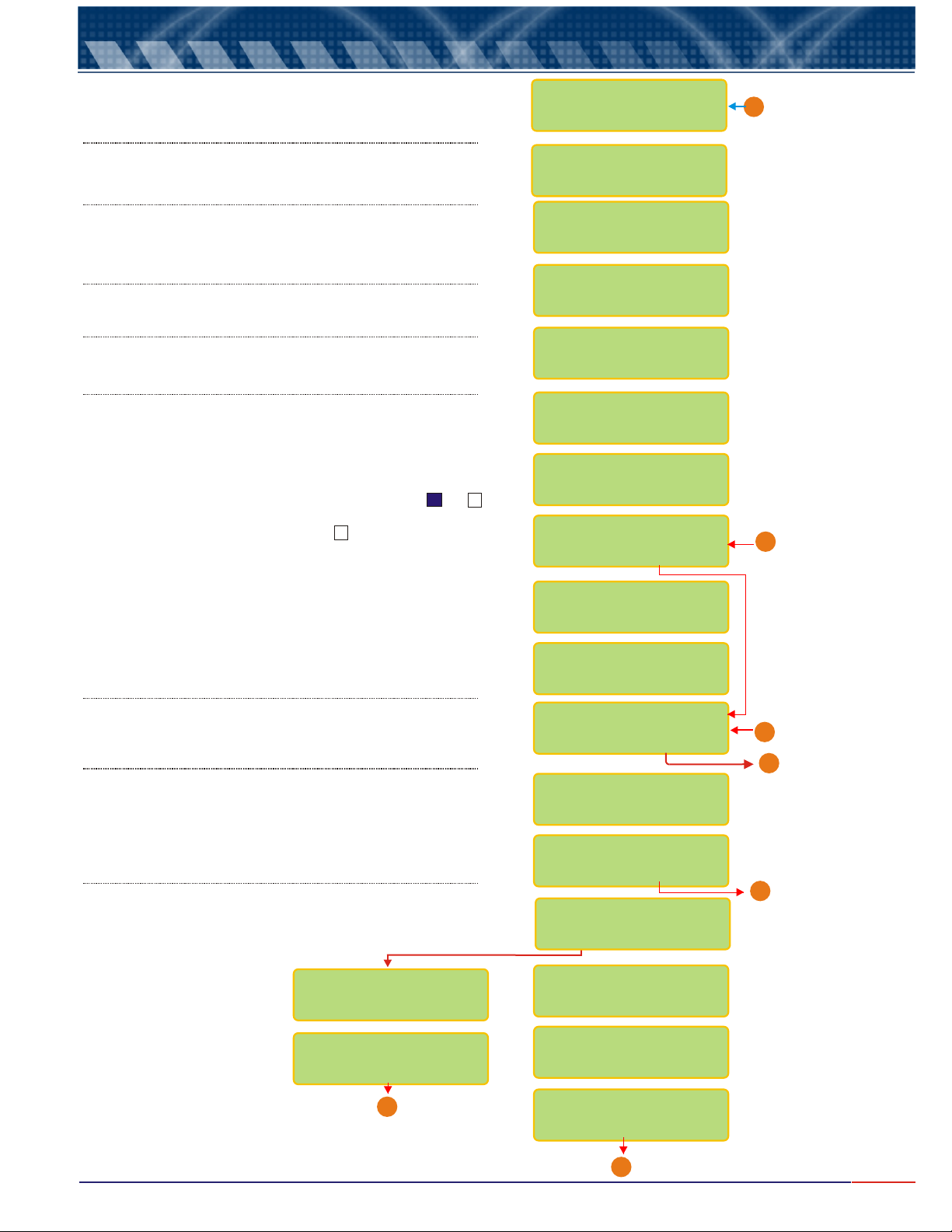
7.
Equipment Operation DO - Set Up (cont.)
User can adjust the value for SP 2.
Refer to Page 13 (Note A) for instruction on how to adjust
this value. Resolution will depend upon the Resolution
chosen while at Set Up..
User can choose the Acting desired.
<SELECT>
Press key to choose the desired option then
<ENTER>
press key to confirm
User can adjust the value for Hystereses.
Refer to Page 13 for instruction on how to adjust this
value. Resolution will depend upon the Resolution
chosen while at Set Up.
User can adjust the percent for Proportional Band.
Refer to Page 13 for instruction on how to adjust this
value.
User can adjust the time for Period.
Refer to Page 13 for instruction on how to adjust this
value.
For the Burn Out configuration, user will have three options as: On - Contact is
going to stay On all the time, Off - contact will stay Off all the time or Hold contact is going to follow the last situation, before going to Hold status.
Press key until the desired option flashes, then press to confirm. <SEL> <ENT>
If user chooses Contact S3 as On, while at Reading Mode, a or a will be
displayed after the S3, indicating that this Contact is On. If user chooses
Contact S1 as Off, while at Reading Mode, a will be displayed after the
S1, indicating that this Contact is Off. Set Point 3 is for Cleaning purpose
Only and it is strongly recommended to use this function for DO
measurements.
User can program the Cleaning Interval (up to 99hours) and also
the Cleaning Time (up to 99minutes). Refer to Page 13 (Note A)
for instruction on how to adjust this value.
X
SET-POINT S2
7.00 ppm <>
ACTING
/ REVERSEDIRECT
HYSTERESES
0.20 PPM <>
PROPORT. BAND:
100% <>
PERIOD:
2s <>
BURN-OUT CONFIG.
STAND-BY: HOLD
CONFIG CONTACT:
S3
SET-POINT S3:
/ OFFON
CLEAN INTERVAL:
24h ><
CLEAN TIME:
20s ><
From Page 15
A
From Page 16
C
User has the option to configure Current.
Press key to choose the desired option then
<SELECT>
press key to confirm.
<ENTER>
User has the option to choose using Output mA-1.
<SELECT>
Press key to choose the desired option then
<ENTER>
press key to confirm.
User has the option to configure Output mA-1.
Press key to choose the desired option then
<SELECT>
press key to confirm.
<ENTER>
VALUE FOR 4 mA
0.00 ppm <>
VALUE FOR 20 mA
20.00 ppm <>
D
Go to Page 18
CURRENT CONFIG?
/ YES NO
OUTPUT CONFIG:
mA-1
OUTPUT: mA-1
/ OFFON
OUTPUT mA-1
/Trans. Control
SET-POINT mA-1
20.90 ppm <>
ACTING
/ REVERSEDIRECT
PROPORT. BAND:
10% <>
From Page 16
B
Go to Page 18
B
Go to Page 18
C
Go to Page 18
A
17
Page 19
7.
Equipment Operation DO - Set Up (cont.)
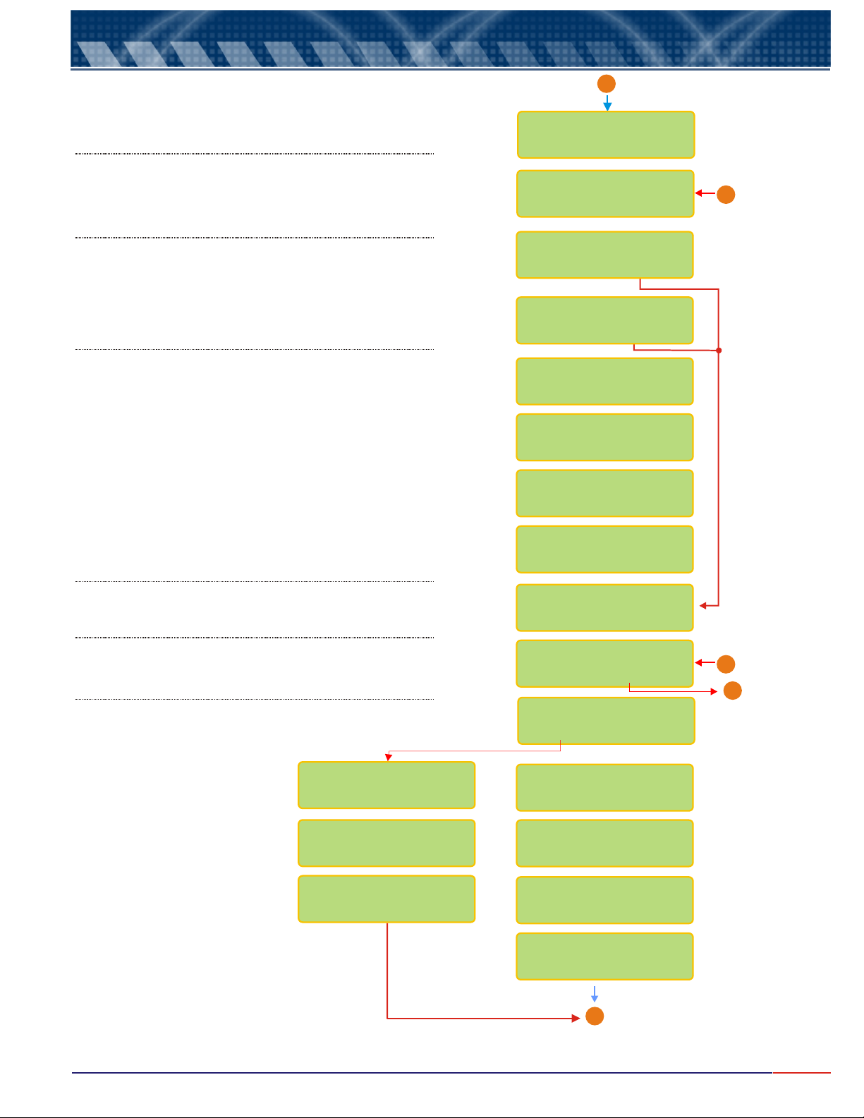
From Pge 17
A
User will be able to adjust the Rate and Reset values. Refer to
Page 13 for instruction on how to adjust these values.
For the Burn Out configuration, user will have three options as:
4mA, 2omA or Hold.
Press key until the desired option flashes, then press
<SEL>
<ENT>
Connect Amp Meter to output 4-20mA mA-1 and it will be possible
to adjust them, then press <ENTER> when ready.
Adjust the value as needed by pressing (to decrease)
or (to increase) keys, so the outputs can be adjusted.
<SELECT>
increase.
to confirm.
User will be able to calibrate output mA-1.
Press key to choose the desired option then
<SELECT>
press key to confirm
<ENTER>
<SELECT>
<ESCAPE>
<ESCAPE>
key will decrease the value and key will
RATE: 5s
RESET: 5s
<
>
<
>
BURN-OUT CONFIG.
STAND-BY: HOLD
CALIBRATE mA-1
/ YES NO
CONFIRM?
/ YES NO
PLACE AMP METER@
OUTPUT 4-20:mA-1
READY?
ADJUST: 4 mA-1
<SEL>- <ESC>+
From Page 17
D
User has the option to choose using Output mA-2.
Press key to choose the desired option then
<SELECT>
press key to confirm.
<ENTER>
User has the option to choose using Output mA-2.
Press key to choose the desired option then
<SELECT>
press key to confirm.
<ENTER>
User has the option to configure Output mA-2.
Press key to choose the desired option then
<SELECT>
press key to confirm.
<ENTER>
VALUE FOR 4 mA
0.00 ppm <>
VALUE FOR 20 mA
60.00 ppm <>
BURN-OUT CONFIG.
STAND-BY: HOLD
ADJUST: 20 mA-1
<SEL>- <ESC>+
OUTPUT CONFIG:
mA-2
OUTPUT: mA-2
/ OFFON
OUTPUT mA-2
/Trans. Control
SET-POINT mA-2
21.00 ppm <>
ACTING
/ REVERSEDIRECT
PROPORT. BAND:
10% <>
RATE: 5s
RESET: 5s
<
>
<
>
A
Go to Page 19
From Page 17
C
B
Go to Page 19
User can program
Set Point 2 for Direct
or Reverse Acting
and also adjust the
Proportional Band
% and also adjust
the values for Rage
and Reset.
Refer to page 13
(Note A) for info on
how to modify this
value.
18
Page 20
7.
Equipment Operation DO - Set Up (cont.)
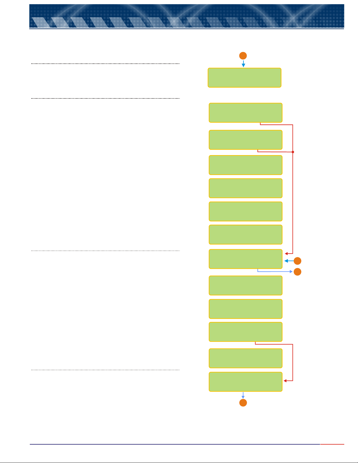
From Page 18
A
For the Burn Out configuration, user will have three options as:
4mA, 2omA or Hold.
Press key until the desired option flashes, then press
<SEL>
<ENT>
Connect Amp Meter to output 4-20mA mA-2 and it will be possible
to adjust them, then press <ENTER> when ready.
Adjust the value as needed by pressing (to decrease)
or (to increase) keys, so the outputs can be adjusted.
<SELECT>
to confirm.
User will be able to calibrate output mA-2.
<SELECT>
Press key to choose the desired option then
<ENTER>
press key to confirm
<SELECT>
<ESCAPE>
<ESCAPE>
key will decrease the value and key will increase.
BURN-OUT CONFIG.
STAND-BY: HOLD
CALIBRATE mA-2
/ YES NO
CONFIRM?
/ YES NO
PLACE AMP METER@
OUTPUT 4-20:mA-2
READY?
ADJUST: 4 mA-2
<SEL>- <ESC>+
ADJUST: 20 mA-2
<SEL>- <ESC>+
User will have the option to configure digital output RS-485 for
Proprietary or Modbus Protocol. Press key to choose
the desired option then press key to confirm .
User can choose the protocol desired.
User can choose the Speed.
User can choose the Bits Number.
User can choose the Parity.
User will be able to define the instrument identification number
within the network, up to 256 instruments. Refer to Page 13 (Note
A) for instruction on how to adjust this value.
<ENTER>
<SELECT>
CONFIG RS-485
/ YES NO
PROTOCOL:
/ PROPR. Modbus
SPEED <100 bps>
24 48 9612
BITS NUMBER
/ 7 8
PARITY:
/ ODDEVEN
Comunication-ID
Number: 1 <>
A
Go to Page 20
From Page 17 & 18
B
END
X
19
Page 21
7.
Equipment Operation DO - Set Up (cont.)
From Page 19
A
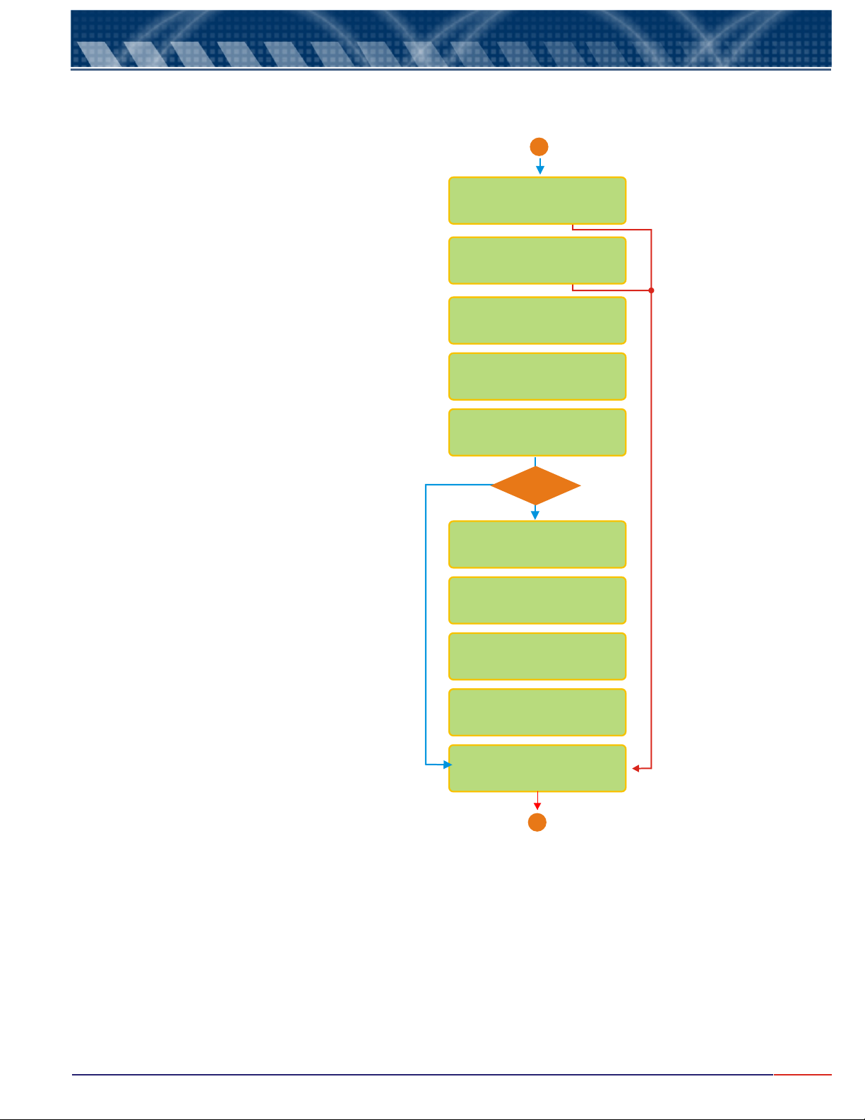
If user is changing the cell of the instrument,
it is necessary to adjust its temperature.
If changing the cell, choose
First find out any sample temperature (any sample,
like tap water), then adjust the temperature at the
screen, to match the sample temperature being used.
Refer to page 13 (Note A) for instruction on how to
modify this value. Dip the cell into the used
sample, then press
Yes and confirm.
key.<ENTER>
NEW CELL?
/ YES NO
CONFIRM?
/ YES NO
THERMOSTATIZE
CELL @ 25ºC <>
THERMOSTATIZE
CELL @ 25ºC<E>
WAIT
STABILIZING
Yes
Temp.
ok?
No
VERIFY SOLUTION
TEMPERATURE
VERIFY CELL
PERSISTING ERROR
CONTACT OMEGA
CUSTOMER SERVICE
(800)872-9436
<ENTER>
================
WAIT
X
END
20
Page 22
7.
Equipment Operation DO - Calibration
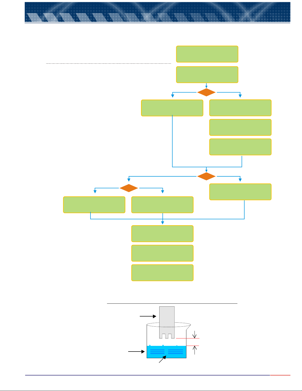
Press until flashes then press key. <SEL> Read <ENT>
Press until flashes then press key. <SEL> Calibrate <ENT>
Depending on option chosen during Set Up Mode for Zero:
Auto Zero or Manual Zero.
Depending on option chosen during Set Up Mode
for Span: Auto Span or Manual Span.
Depending on option
hosen during Set Up
Mode for Calibration
Type: in Air or in Water
SIMULATE 100%
HUMIDITY
Air
CAL. IN
DISSOLVED OXYGEN
Auto
WAIT
AUTO ZERO
Auto
Water
DIP CELL INTO
AIRY WATER
/READ SET UP
DO: READ /
CALIBRATE
ZERO
Manual
PLACE CELL @
ZERO CHEMICAL
WAIT ZERO
SPAN
Manual
PLACE CELL
IN: 7.50 ppm
READY?
CHEMICAL
Simulate 100% Humidity as shown on below picture.
This option is show if user had chosen to calibrate in
Air. Press key when ready. <ENT>
Dip Cell into sample to be measured. Make sure that
the sample is being stirred.
Stirring is crucial for DO measurement and without it
the result will not be correct!
Then press key when ready.<ENTER>
Follow this procedure in order to simulate 100% humidity.
Level
READY?
================
WAIT
GO TO SAMPLE!
READY?
Cell
Distilled Water
Airy water is water place inside a
Reservoir and O2 is directly
pumped inside this reservoir,
mixing with the water.
Press key when ready. <ENT>
10mm
21
Page 23
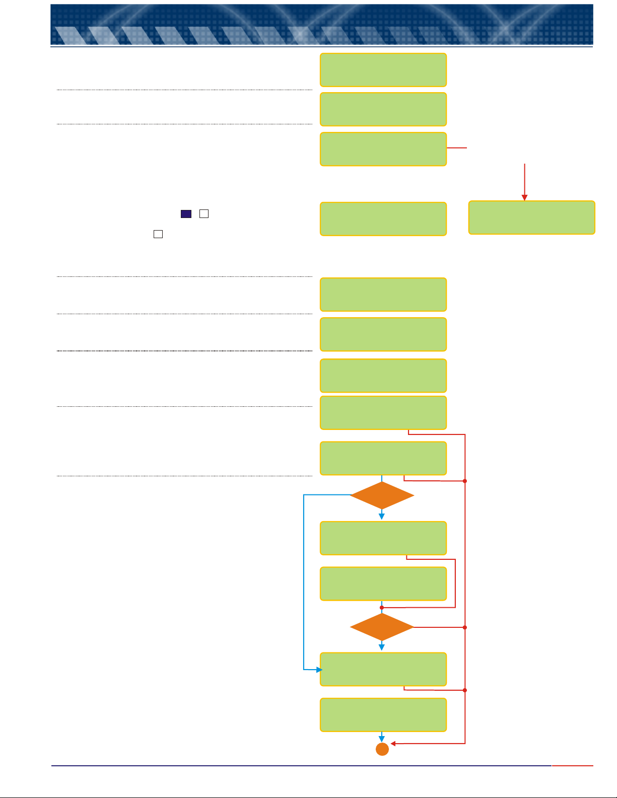
10.
7.
pH/Leitura
Equipment Operation DO - Read
Press until flashes then press key. <SEL> Read <ENT>
Press until flashes then press
<SEL> Read <ENT>
key.
Dip Cell into sample to be measured. Make sure that
the sample is being stirred.
Stirring is crucial for DO measurement and without it
the result will not be correct!
Then press key when ready.<ENTER>
The reading will be displayed and also the Set Points conditions. If user had
chosen Contacts (S1, S2 and S3) as On, a or will be displayed after the
Contact Set Point number, indicating that this Contact is On. If user ha chosen
Contacts (S1, S2 and S3) as Off, a will be displayed after the contact Set
Point number, indicating that this Contact is Off. Set Point 3 is for Cleaning
purpose Only and it is strongly recommended to turn On this Set Point.
Press and it will be able to verify the temperature <SEL>
Press and it will be able to verify the values
<SEL>
for Current Output, chosen during Set Up Mode.
X
DISSOLVED OXYGEN
READ/SET UP
DO - /
READ
CALIBRATE
GO TO SAMPLE!
READY?
S1:» S2:» S3:»
-> 49.98ppm
S1:» S2:» S3:»
23.2ºC
mA-1: 4.00mA
mA-2: 20.00mA
Reading display, when the
bargraph function was not
chosen durign Set Up Mode.
================
-> 49.98ppm
Press and it will be able to adjust the value Read, if
<SEL>
chosen this procedure during Set Up Mode (On Line
Calibration-page 13). Refer to page 13 for instructions on how
to adjust this value.
<SEL>
Press and it will be able to fine tune the
Current outputs (mA-1 and mA-2, if they were
chosen for Control Purpose (pages 17 & 18), based
on the process situation.
Confirm the opiton chosen.
At this point the user will be able to adjust the mA
Output Current. Press to decrease the
value or
should be adjusted until reached an ideal current
output value for the value being read by the cell
<ESC> toincrease the value this value
<SEL>
.
ON LINE CALIBR.:
3.93ppm <>
FINE TUNE PROC,?
/ NOYES
CONFIRM?
/ YES NO
No
CONTROL
for mA 1?
Yes
FINE TUNE mA-1?
/ YES NO
<SEL>10.00<ESC>
3.93ppm mA-1
CONTROL
for mA 2?
Yes
No
FINE TUNE mA-2?
/ YES NO
<SEL>10.00<ESC>
3.93ppm mA-2
X
END
22
Page 24
8.
CN1
1
CN3CN2 CN4
RS485
S2
mA-2
2
3
S3
mA-1
AC
Na
S1
C
Med.
Blind.
Am
Vd
TERMO
Ref.
4
5
F4
F3
F2 F1
11
8
6
7
9
10
17
14
12
13
15
16
20
18
19
Na
C
Na
C
Maintenance
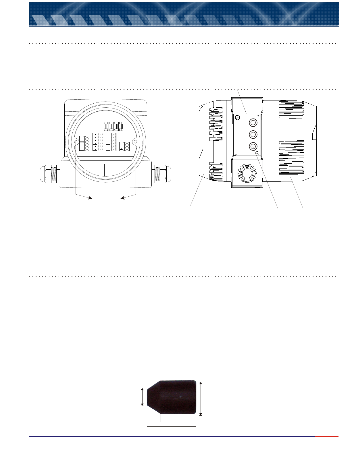
Case Disassemble/Aseemble Method
This method has an objective to instruct technical personal for assemble and disassemble or the case.
Necessary Material: Hex Tool ¼ “
Parts Description
ID Tag
SEL.
ENT.
ESC.
Nuts
Back Lid
Desassemble Porceedures
Command
Keys
Frontal Lid
1 - Unscrew back and front al lids.
2 - Using a Hex Tool 1/4", unscrew nuts used to attach the electronic circuit boards set to the case.
3 - Remove the electronic circuit boards, from the back lid, being careful not to damage the circuits.
Assemble Proceedures
1 - Place the electronic circuit boards set inside the case, insert if from back lid.
2 - Using the Hex Tool, re-attach the electronic circuit boards to the case, by the nuts.
3 - Thread the front and back lids to the case.
Note: If necessary to maintain the command keys, execute the following steps:
1 - Remove identification Tag;
2 - Using the Rubber device (need to request from factory), press with some pressure over the command
keys and turn it counter clockwise in order to unscrew it;
3 - Remove the spring and the contact pin;
4 - Make the necessary maintenance and proceed with the assembly, following the same steps in reverse.
Rubber Device
ø 10 ø 20
22
30
* Dimensions in miliímeters
23
Page 25
9.
A periodical cell maintenance consists of replacing the ELECTROLYTE, the MEMBRANE and cleaning of the
Ag/AgCI/Pt ELECTRODE. The maintenance must be executed when notice sensibility lost during calibration or
frequent deviations of the calibrated value.
These factors could occur caused by: Silver Phosphate clogging at the Anode, impurity clogging, grease or even
membrane mechanical damage. Initiate this operation by replacing the electrolyte solution, if necessary proceed
with Ag/AgCI/Pt Electrodes cleaning (verify again) and if even needed, replace the membrane.
ATTENTION
Cell Maintenance
The Silver Anode is treated superficially with Silver Chloride, presenting a dark grey color and this is normal.
Electrolyte Replacement
The electrolyte consists of a Tribasic Phosphate Sodium solution (Na3 PO4 .12H2O) . In order to replace it, proceed
as follow:
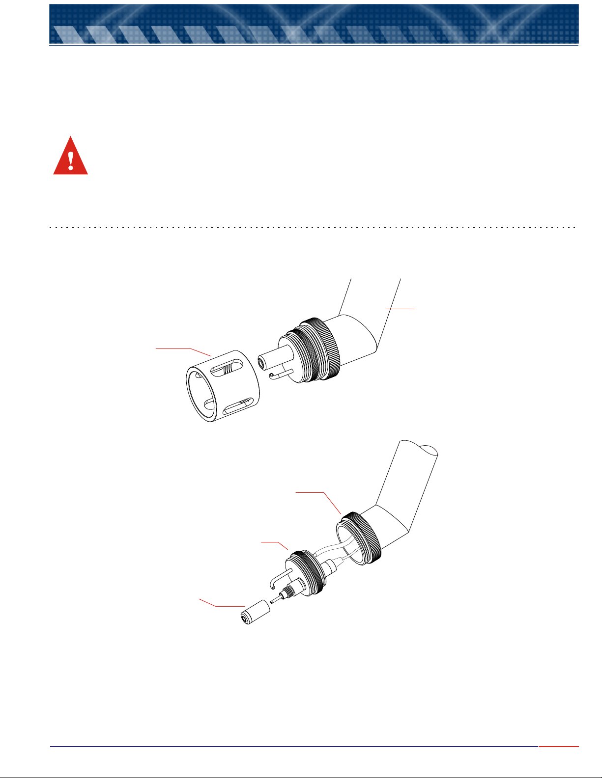
1. Unscrew the Cell and Tip Protection Cap from the body, as shown below.
Cell Body
Cell and Tip
Protetion Cap
2. Unscrew the Electrolyte Reservoir.
Electrolyte
Reservoir
Attachment
Ring
Cell Base
3. Wash the Electrolyte Reservoir interior and exterior using distilled or deionized water
4. Rinse it with Tribasic Phosphate Solution, provided with the unit, then remove it immediately.
5. Fill the Electrolyte Reservoir with Tribasic Phosphate Solution (DOA-21RS) up to the beginning of the internal
thread. Make sure small bubbles will not be created while filling the reservoir. Shack or tap the Reservoir in order to
remove these bubbles. Bubbles will interfere with the reading!
6. Reinstall the Electrolyte Reservoir into the cell being careful in order not to touch or damage the membrane.
7.Proceed with the instrument calibration.
24
Page 26
9.
Cell Maintenance (cont.)
Membrane Replacement
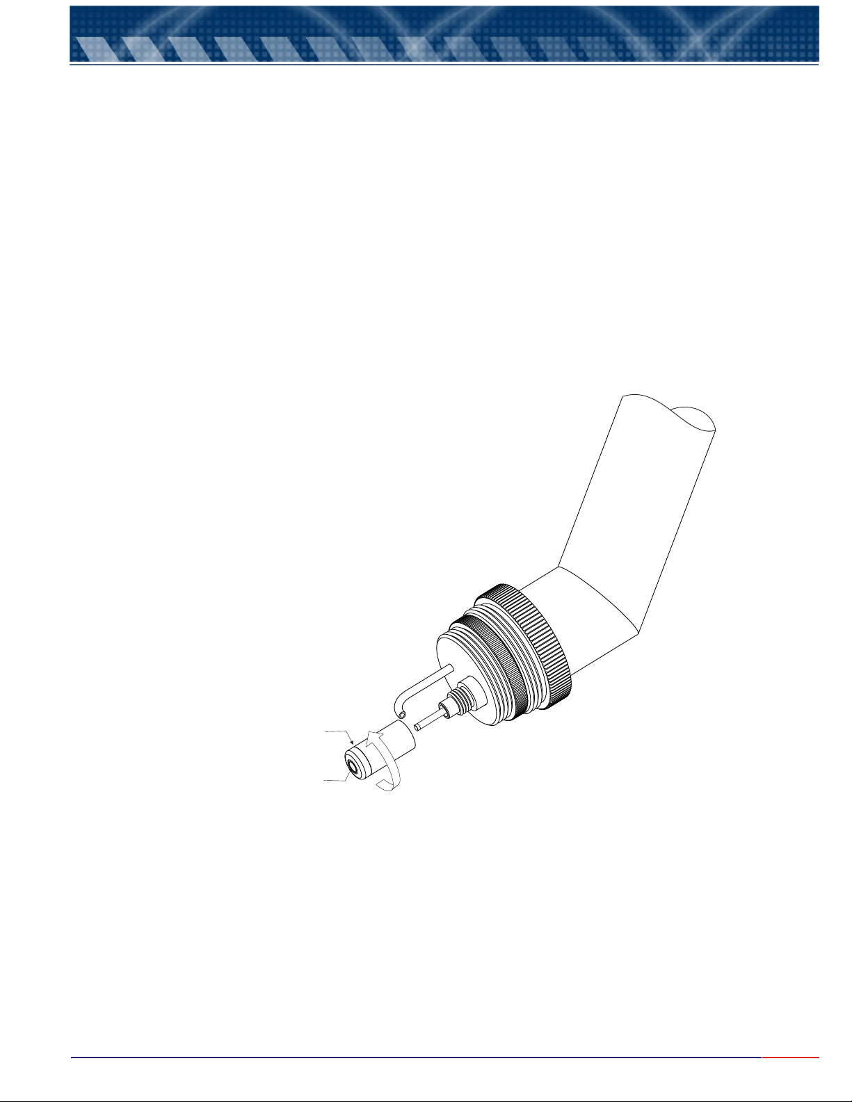
In order to proceed with the membrane replacement, the cell is supplied with an Industrial Cell Maintenance Kit
(DOA-21MK) composed of 6 Electrolyte Reservoir, already supplied with its own membrane and
Electrolyte Solution (DOA-21RS).
In order to replace the membrane, just un-thread and remove the old Electrolyte Reservoir and discard it.
Fill up the new Electrolyte Reservoir, up to the beginning of the thread, using the electrolyte solution (DOA-21RS)
supplied with the instrument, dropping it gently into the reservoir, avoiding to generate bubbles.
Bubbles will interfere with the reading and must be avoided.
After replacing the membrane, look at the membrane tip and inspect it visually, if noticed any bubble presence,
remove the Electrolyte Reservoir, tip it using your finger tips by tapping on it so he micro bubbles can be released
from the membrane.
Refill the reservoir, up to the beginning of the thread and screw it back at the cell and visually re-inspect for bubbles,
again!
Electrolyte Reservoir
Membrane
25
Page 27
9.
Cell Maintenance (cont.)
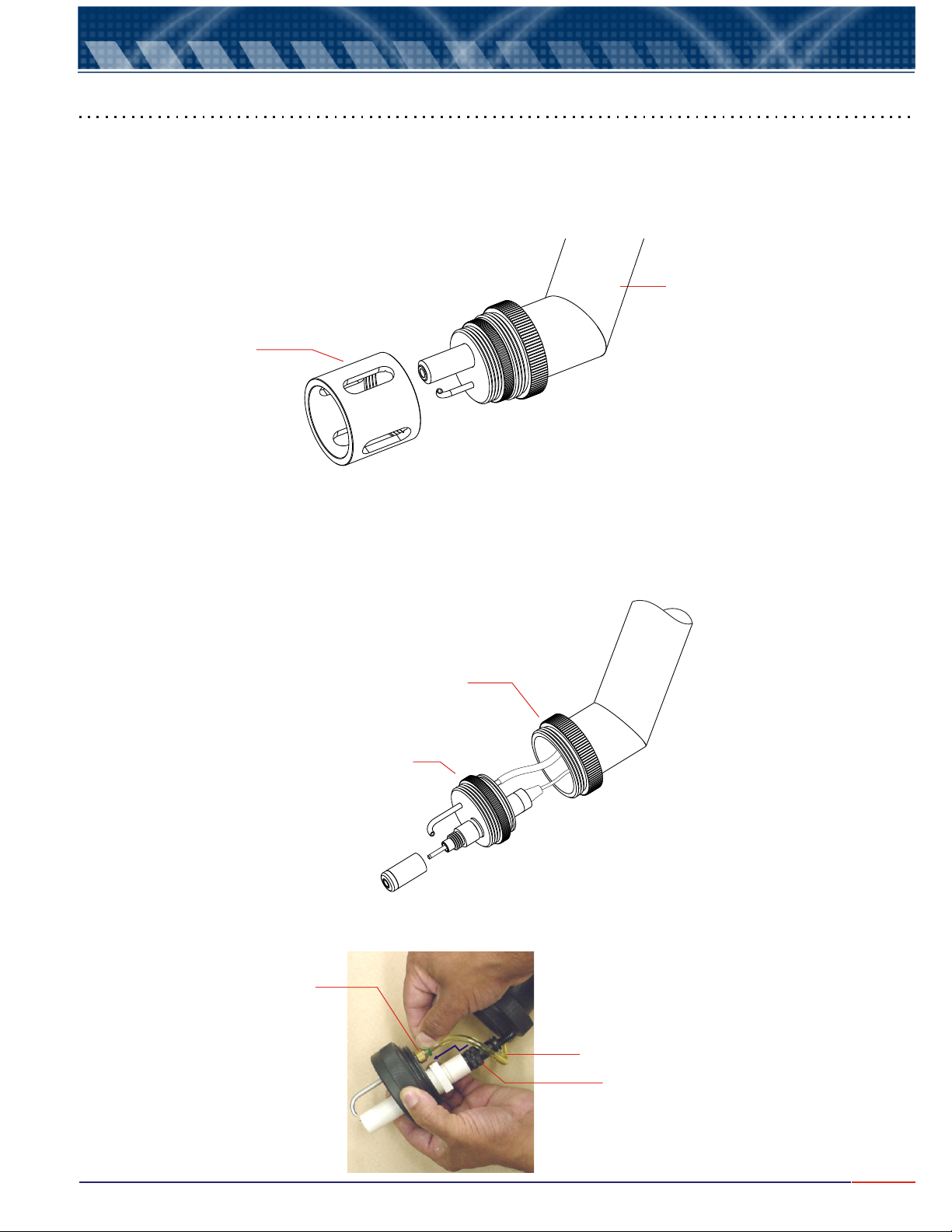
Cell Replacement
In order to proceed with the DO Cell (DOE-441-R) replacement, follow as below.
1. Unscrew the Cell and Tip Protection Cap (shown at figure A).
Cell and Tip
Protetion Cap
Figure A
Cell Body
2. Unscrew the attachment ring (shown at Figure B);
2.1 Pull out the cell base up to the cable extension limit and the air cleaning hose (shown at figure B);
2.2 Unscrew the cell connector from the cell, then disconnect the cleaning hose pushing the quick connect
(making an “L” movement), in order to remove the cleaning hose (shown at figure C);
Attachment
Ring
Cell Base
Figure B
Quick
Connect
Cleaning
Hose
Cell
Conector
Figure C
26
Page 28
9.
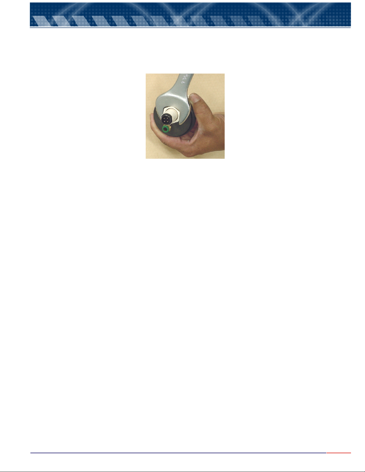
2.3 Move the base to a bench in order to start the membrane replacement;
2.4 Using an 27mm or 1” 1/6 tool, unscrew the H-8 connector and remove the cell (shown at figure D);
3. With the new cell on hands, proceed with the reverse operation as described above and on page 26.
Cell Maintenance (cont.)
Figure D
27
Page 29
9.
Cell Maintenance (cont.)
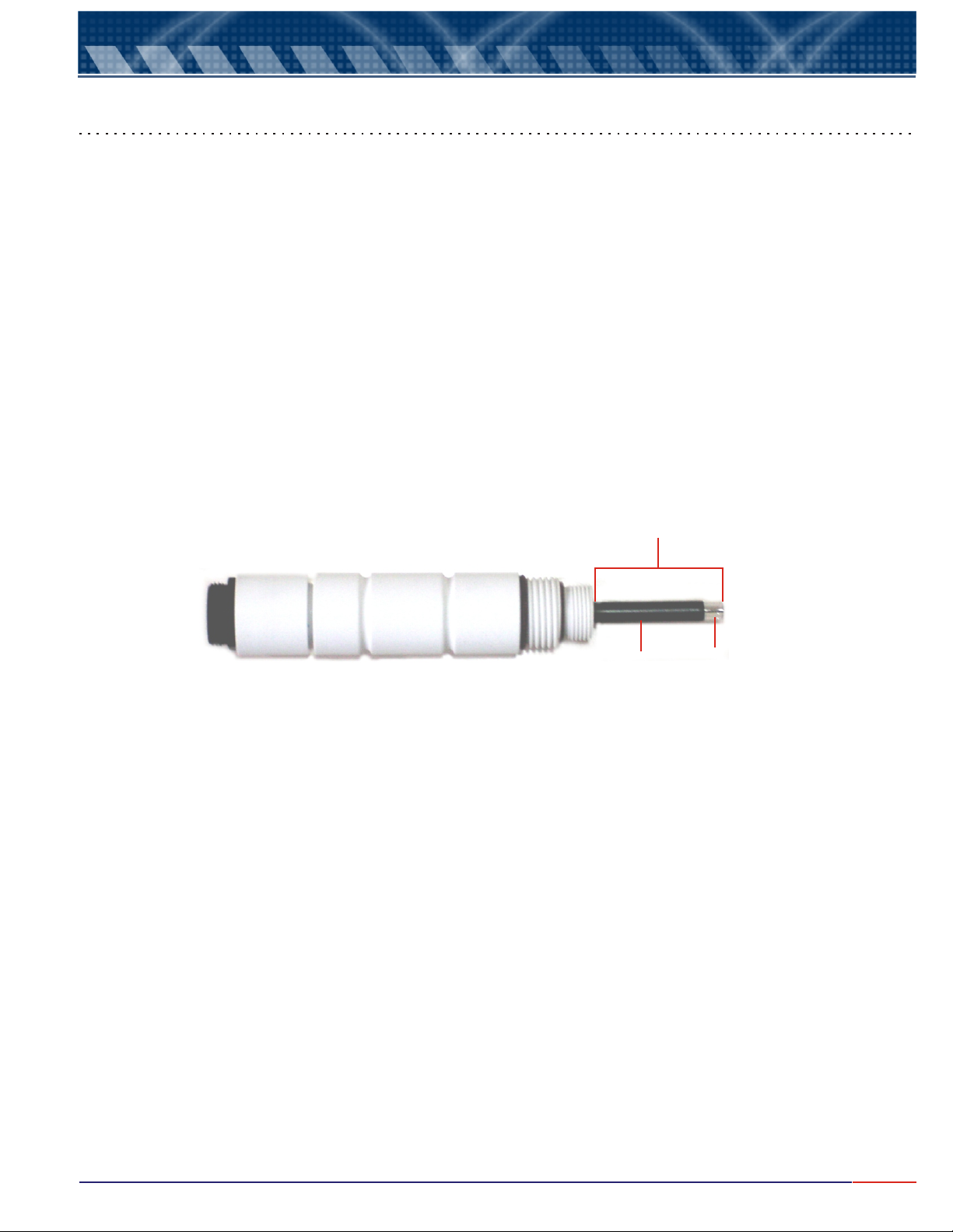
Ag / AgCl / Pt Electrode Cleaning
The Cell electrode is composed internally by a silver anode that is superficially treated presenting a dark grey
color and Pt cathode. This electrode offers a limited life and requires maintenance. But, its use in contemned
solutions, cause the anode to get dirty and requires a periodical cleaning.
In order to clean the cell electrode, proceed as:
1. Unscrew the Cell Protection Cap;
2. Unscrew the Electrolyte Reservoir being careful in order not to touch or damage the membrane;
3. Wash the electrode using deionized water;
4. Using a soft absorbent paper, carefully clean the anode and cathode; rinse using deionized water;
5. Refill the Electrolyte Reservoir with electrolyte (DOA-21RS) up to the beginning of the thread and screw it
back to the Electrode, like described on prior pages of the Cell Maintenance.
Electrode
Anode
Cathode
28
Page 30

10.
1) Proprietary:
Order:
ESC ID P CR LF
0x1B 0x50 0x0D 0x0A Hexadecimal
Answer:
L > > V V V V V V mgO2/L C C C C C C m A
Example of answer for an un-stable value
L > 5 . 0 0 mgO2/L 1 2 . 0 0 m A
Example of answer for a stable value
Proprietary Communication Protocol
The ID is configured at the instrument from 1 to 32.
L > > 5 . 0 0 mgO2/L 1 2 . 0 0 m A
Note: a) When the answer comes a C instead of a L, it means that the equipment is under
calibration function (is being operated in location by the user, executing the calibration
operation at the instrument).
b) When the answer comes an S instead of a L, it means that the equipment is under Set Up
function and it is being operated in location by the user.
2) RS485 – It is a “physical location”, where the proprietary protocol will be “transported”.
As factory default, this communication comes configured as:
Speed = 9600
Parity = none
Number of Bits = 8
Stop Bit = 1
ID = 1
29
Page 31
Page 32

M-4520/0908
 Loading...