

Page 1

USER’S GUIDE
Series CP/CN/CT/CX |
CoolPoint® Vortex Shedding
Flowmeter
Specifications - Installation and Operating
Instructions
dwyer-inst.com | [email protected]
For latest product manuals:
dwyer-inst.com/en/instruction-manuals Bulletin F-CP-CN-CT-CX
Page 2

CONTACT
Dwyer Instruments, LLC
dwyer-inst.com/en/contact-us
Toll-Free:
1-800-872-9141
(USA only)
Telephone:
(219) 879-8000
Fax:
(219) 872-9057
Email: [email protected]
The information contained in this document is believed to be correct,
but Dwyer accepts no liability for any errors it contains, and reserves
the right to alter specifications without notice.
Page 3

Table of Contents
1. Introduction ......................................................................................................................................................................... 4
2. Specifications ..................................................................................................................................................................... 4
3. Installation ........................................................................................................................................................................... 8
4. Electrical Connections ..................................................................................................................................................... 8
5. Operation ............................................................................................................................................................................. 9
6. Setup And Configuration ................................................................................................................................................. 10
6.1. Initial Power Up.....................................................................................................................................................................10
6.2. Model CT .................................................................................................................................................................................10
6.3. Configuring the solid state relay as alarm output: .................................................................................................10
6.4. Alarm Relays and Pulse Output .....................................................................................................................................11
6.5. Configuring the Solid State Relay as Pulse Output: ...............................................................................................11
6.5.1. Pulse Output....................................................................................................................................................................11
6.6. Configuring the Temperature Alarm .............................................................................................................................11
6.7. Configuring Response Time in Filter Mode: ............................................................................................................... 13
6.8. Step Response Graphs for Various Filter Settings ..................................................................................................13
7. Maintenance/Repair .......................................................................................................................................................... 14
8. Warranty/Return................................................................................................................................................................. 14
9. FCC Compliance ............................................................................................................................................................... 14
Table of Contents
3
Page 4

1. Introduction
The Series CP/CN/CT/CX CoolPoint® Vortex Shedding Flowmeter is made for water, water/glycol mixtures, or low
viscosity uids. These units contain no moving parts to clog or wear, allowing for minimal maintenance in the eld.
This series has two versions: a 3-wire version, where power is supplied separate from the 4 mA to 20 mA output,
and a 2-wire loop-powered version. The 3-wire version is equipped with a solid state relay that can be congured
in the eld to be either an alarm or a pulse output, an LED display which allows the user to choose between
selectable engineering units (GPM or LPM), and a high temperature option. The alarm on this version is selectable
between a high or low alarm (NO or NC) and the pulse output option is set at a frequency at a specic pulses
per gallon. The 2-wire option allows for operation in an intrinsically safe mode only when used in conjunction with
an approved intrinsic safety barrier meeting required entity parameters. This version does not come with a display
or relay contacts to allow for this operation mode.
2. Specifications
Service: Compatible liquids.
Range: See ow rate chart.
Display: 3-digit or 4-digit LED (pipe sizes > 76.2 mm [3 in]), 7.6 mm (0.3 in) digit height; CP-V8: 3-digit LCD (6-digit
LCD totalizer mode), 7.6 mm (0.3 in) digit height.
Wetted Materials: Flow body: 316 SS or brass; Sensor: PEEK; Seals: FKM.
Accuracy: Flow: ± 2 % FS; Temperature: ±0.1 °C (± 2 °F) (model selectable).
Repeatability: ± 0.25 % of reading.
Turndown: 10:1 (20:1 optional).
Temperature Limits: 2 °C to 99 °C (35 °F to 210 °F).
Pressure Limits: 0.7 bar to 20.7 bar (10 psig to 300 psig); CP ange and CX: 20.7 bar (200 psig) max.
Response Time: 450 ms
Power Requirements: 10 V dc to 30 V dc @ 80 mA standard; 25 mA for 2 wire option; CP-V8: 2 AA alkaline
batteries, not included (45 day battery life).
Output: 4 mA to 20 mA; 100 pulses per gallon (3-wire models only); 2 in, 3 in, and 4 in: 25 pulses per gallon.
Deadband: Alarm output: 2.5 % FS for up to in; 5 % FS for larger than in.
Viscosity: 15 cP max.
Enclosure Rating: NEMA 4X (IP65).
Process Connection: Female NPT, BSPT, or BSPP (model selectable).
Electrical Connection: Male DC micro 5 pin connector; Pigtails or junction box with terminal strip (model
selectable).
Weight: CX: 0.7 kg (1.5 lb); CP: 1.5 kg (3.3 lb); CP-V8: 1.8 kg (4 lb); CN, CT: 3.2 kg (7 lb).
Compliance: CE, ETL.
4 Series CP CN CT CX User's Manual
Page 5
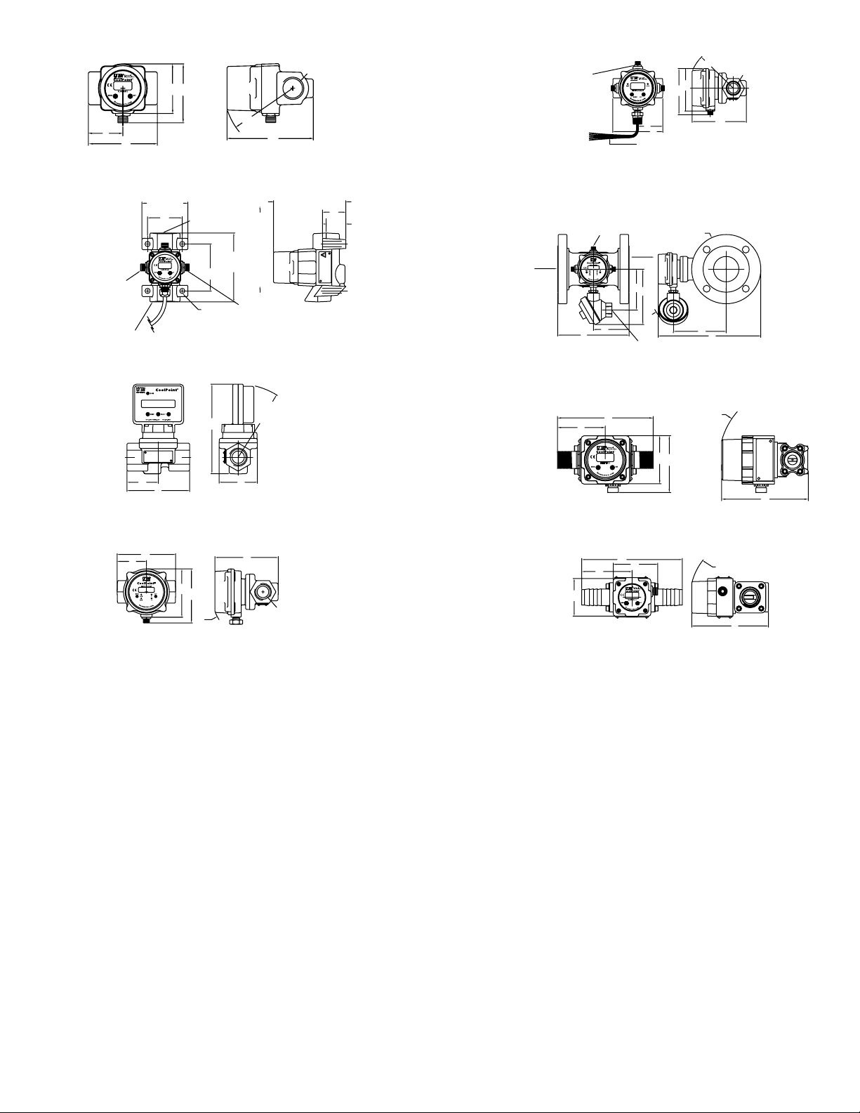
A
NPT FEMALE
CONNECTION
IN
NPT FEMALE
N
CONTROL BOX CAN
BE ROT
PIG TAIL CONNECTION
A
CONNECTION
B
C
F APPROXIMATE
B
E
FLOW
CONTROL BOX CAN BE ROTATED
CONDUIT CONNECTION
3-1/4 MAX.
[33 MM]
DETENTED POSITIONS
POSITION N2
E
F APPROXIMATE
ATEDTO ANY
OF [4] DETENTED
F
E
OUT
POSITIONS IN
90° INCREMENTS
C
CONNECTIO
E
F
B
POSITION N3
CONTROL BOX
CAN BE ROTATED
TO ANY OF [4]
IN 90° INCREMENTS
IN
[83 MM]
A
CP2, CP3, CP4
B
POSITION N4
OUT
4.592 MAX.
[117 MM]
A
MOUNTING LUGS FOR
Ø.31 [5/16] BOLTS. [4] PLACES.
CPM8
D
OUT
C
CPX-V8
C
D
5 MAX. [127 MM]
FLOW DIRECTION
POSITION N1
E APPROXIMAT
SWING RADIUS
ØH
D
G
D
B
A
OPTIONAL -C2
CTx (shown with -C2 pig tail connection)
C
1.312
TO ANY OF [4] DETENTED
POSITIONS IN 90° INCREMENTS
FLOW
B
B
OUT
E
F
C
.500-14 NPT
SWING RADIUS
C
D
CXX-M5
IN
A
CP24, 32 (shown with -C3/-C14 conduit box)
A
B
CP/CN6, CP/CN8, CN12, CN16
D
E
F
C
NPT FEMALE
D
A
CX8-M7
SWING RADIUS
E
Figure 1: Dimensions
5Specications
Page 6

Model Option A in [mm] B in [mm] C in [mm] D in [mm] E in [mm] F in [mm] G in [mm] H in [mm]
FLOW [GPM]
50GPM
CT2-CT8
CT12,
CT16
CP2-V8
CP3-V8
CP4-V8
CP6-V8
CP8-V8
CP12-V8
CP16-V8
Standard
4-1/2 [114.3] 2-1/4 [57.15]
6-3/4
[171. 4 5]
1-5 3/6 4
[46.48]
3-3/8 [85.72]
3-21/32
[92.71]
2-1/4 [57.15] 4-1/2 [114.3] 2-3/4 [69.8 5]
3-3/8 [85.72]
6-3/4
[171. 4 5]
4- 3/64
[102.62]
4-23/32
[119. 85]
2-3/8 [60.32]
2-7/8 [ 73.02]
CPM8 2-7/8 [ 73] 2-1 /2 [63 . 5] 2 [51] - - - - -
CP2,
CP3, CP4
CN6,
CN8
CP6, CP8 4-1/2 [114.3] 2-1/4 [57.15]
CN12,
C1 and C2
options
CN16
CP24
CT24
CP32
CT32
CP2,
CP3, CP4
CN6,
CN8
3-1/4 [82.55]
4-1/2 [114.3] 2-1/4 [57.15]
6-3/4
[171. 4 5]
7-3/4
[196. 85]
10-3/4
[273.05]
3-1/4 [82.55]
4-1/2 [114.3] 2-1/4 [57.15]
CP6, CP8 4-1/2 [114.3] 2-1/4 [57.15]
CN12,
CN16
CP12,
CP16
C3 = Conduit
box
6-3/4
[171. 4 5]
6-3/4
[171. 4 5]
CT2-CT8 4-1/2 [114.3] 2-1/4 [57.15]
CT12,
CT16
CP24
CT24
CP32
CT32
CX8
CX2,
CX3, CX4
CX6, CX8
CX2,
CX3, CX4
CX6, CX8
M7 = Hose
barb
M8 = Nylong
Endcaps
T1 = NPT
female thread
T1 = NPT
female thread
T6 = NPT
male thread
T6 = NPT
male thread
6-3/4
[171. 4 5]
7-3/4
[196. 85]
10-3/4
[273.05]
3-3/16
[80.96]
2-1 /2 [63 . 5]
1-6 3/6 4
[50.29]
2-3/8 [60.32]
2-3/8 [60.32]
3-5/16
[83.82]
1-11 /6 4
[41.15]
3-1/4 [82.55]
3- 35/64
[9 0.17 ]
4- 3/64
[102.62]
3-3/8 [85.72] 4-1 /4 [10 7.7 ]
3-7/8
[98.55]
5-3/5
[136.65]
1-11 /6 4
[41.15]
8-29/32
[226]
9-15/ 32
[240]
5-13/32
[1 37.1 6]
5-11/16
[144 .53]
6- 33/64
[16 5.61]
3-3/8 [85.72] 6 [152.4]
3- 3/5 [91.44] 6 -7/8 [ 174.5]
6- 3/6 4
[16 5.61]
3-3/8 [85.72]
3-7/8
[98.55]
5-3/5
[136.65]
6-23/6 4
[161. 54]
4- 61/64
[125.73]
3-31/32
[100.84]
4-3/4
[120.65]
4-23/32
[119. 85]
6- 39/6 4
[167. 8 9]
6-23/32
[174 . 5]
8-29/32
[226]
9-15/ 32
[240]
2-1 /2 [63 . 5]
2-13/32
[60.96]
2-13/32
[60.96]
2-13/32
[60.96]
2-23/64
[59.94]
2-13/32
[60.96]
4- 59/6 4
[124.97]
6-9/64
[155.96]
5-29/32
[50.11]
6-7/16
[16 3.51]
7-11 /1 6
[195. 33]
4- 5/6 4
[103.38]
4- 39/6 4
[116.84]
4- 59/6 4
[124.97]
5- 55/64
[148.59]
11-1 /8
[282.57]
12 -37/64
[319.48]
4- 5/6 4
[103.38]
4- 39/6 4
[116.84]
4- 59/6 4
[124.97]
5- 55/64
[148.59]
6-9/64
[155.96]
4- 59/6 4
[124.97]
6-9/64
[155.96]
11-1 /8
[282.57]
12 -37/64
[319.48]
2-27/3 2
[72.14]
2-13/16
[71.37]
4-13/16
[122.17]
2-13/16
[71.37]
2-13/16
[71.37]
2-13/16
[71.37]
3-3/4 [95.25]
3-3/4 [95.25]
4- 61/64
[125.73]
5-17/6 4
[133.6]
4-3/16
[106.43]
4-3/16
[106.43]
- -
-
- - -
- - -
6 [152.4] - - -
2-15/6 4
[59.44]
2-3/4 [69.8 5]
3-3/4 [95.25]
2-49/64
[70.36]
3-3/16
[80.96]
4-3/16
[106.43]
- -
- -
- -
2-7/8 [ 73.02] 3-1/4 [82.55] - -
11-1 /8
[282.57]
12 -37/64
[319.48]
2-15/6 4
[59.44]
2-3/4 [69.8 5]
3-3/4 [95.25]
2-7/8 [ 73.02]
3-3/4 [95.25]
3-3/4 [95.25]
3-3/4 [95.25]
11-1 /8
[282.57]
12 -37/64
[319.48]
4-21/32
[118. 27]
4-21/32
[118.36]
4-9/32
[10 8.71]
4- 55/64
[123.19]
4-9/32
[10 8.71]
4- 55/64
[123.19]
7-1/2
[190. 5]
9
[228.6]
6-13/3 2
[162. 81]
6- 51/64
[172.47]
7-51/6 4
[198.04]
6- 55/64
[173.99]
7-51/6 4
[198.04]
7-51/6 4
[198.04]
7-51/6 4
[198.04]
7-1/2
[190. 5]
9
[228.6]
3- 39/6 4
[91. 69]
3- 39/6 4
[91. 69]
3- 39/6 4
[91. 69]
3-13/16
[96.52]
3- 39/6 4
[91. 69]
3-13/16
[96.52]
5-47/64
[146]
6-7/16
[16 3.51]
- -
- -
- -
- -
- -
- -
- -
5-47/64
[146]
6-7/16
[16 3.51]
- -
- -
- -
- -
- -
- -
7-1/2
[190. 5]
[228.6]
7-1/2
[190. 5]
[228.6]
9
9
6GPM
12GPM
25GPM
4GPM
100GPM
200GPM
300GPM
200
250
300
600GPM
500
12
10
8
5
2
1
.5
.2
PRESSURE DROP [PSID]
.1
.05
.3 .6 12 510152550 100
6 Series CP CN CT CX User's Manual
Page 7
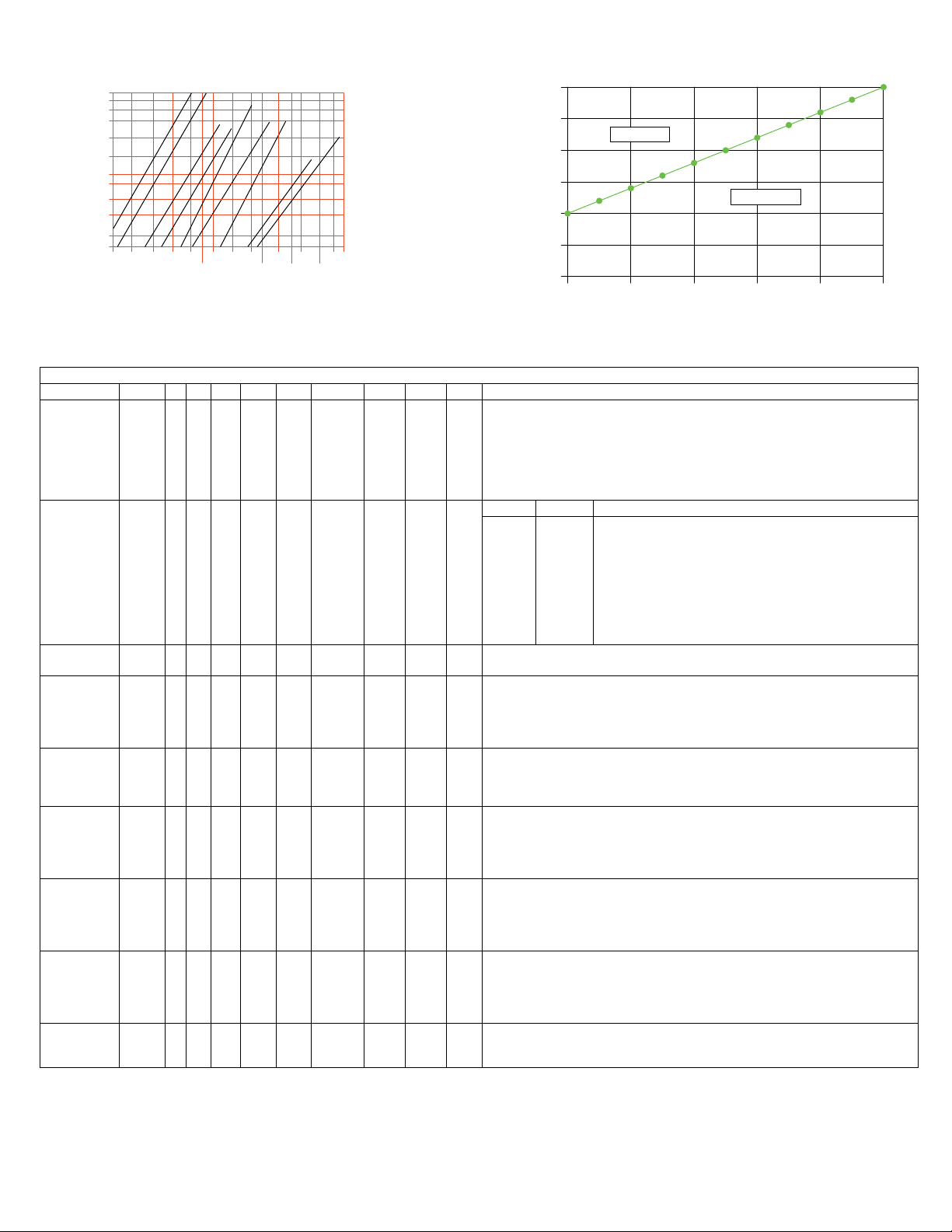
Ø [OHMS]
1000
MAXIMUM LOAD RESISTANCE VS. SUPPLY VOLTAGE
VDC
FLOW [LPM]
MILLIBAR
M
PM
M
1000
750
600
350
200
100
50
35
20
10
5
3.5
2510 203050 100 200
45LPM
95LPM
15LPM
22.7LP
380LPM
760LPM
1100LPM
300
190L
800
1200
1500
2300LP
2000600
30
25
20
15
10
5
0
0
SUFFICIENT
200 400 600 800
MODEL CHART
Example CP 2 -M1 T1 C1 -W1 CP2-M1T1C1-W1
Series
CX
CP
CN
CT
Polysulfone body vortex shedding owmeter
Metal body vortex shedding owmeter with rotatable display
Metal body vortex shedding owmeter
Metal body vortex shedding owmeter with temperature sensor and
rotatable display
CPM
Polysulfone body vortex shedding owmeter with integral lugs integral to
body for concrete trucks (only available with pipe size 8 or 1˝)
GPM LPM
2
3
4
Pipe Size
6
8
12
16
24
32
Battery
Option
-
V8
M1
M2
Material
M5
M7
M8
Process
Connection
Electrical
Connection
Output and
Display
Orientation
Special
Options
T1
T2
T3
T6
C1
C2
C3
C7
C14
-
D1
D3
D4E10
D4E1
-
N1
N2
N3
N4
E14
NIST
W1
3
6
12
25
50
100
200
300
600
11
23
45
95
190
380
750
1136
2271
8 mm (1/4 in)
10 mm (3/8 in)
15 mm (1/2 in)
20 mm (3/4 in)
25 mm (1 in)
40 mm (1-1/2 in)
50 mm (2 in)
80 mm (3 in)
100 mm (4 in)
No battery
Battery operated
Brass
316 SS
Polysulfone
Brass with nylon endcaps
Brass with nylon hosebarbs
NPT female
BSPT
BSPP
NPT male
Male 5 pin
3-wire pig tail leads 1 m (3.3 ft)
Aluminum conduit box
3-wire pig tail leads with PG7 connector 1 m (3.3 ft)
316 SS conduit box
4 mA to 20 mA output with high and low solid state relays
4 mA to 20 mA out with 3 digit of rate display (only for series=CPM)
Pulse out with 3 digit display of total (only for series=CPM)
Pulse out no display (only for series=CPM)
4 mA to 20 mA out with no display (only for series=CPM)
Standard display orientation
Flow right
Flow up
Flow left
Flow down
4 mA to 20 mA 2-wire, intrinsically safe
NIST traceable calibration certicate
20:1 extended turndown
INSUFFICIENT
7Specications
Page 8
3. Installation
WHITE
LOAD
T
5: FLOW RELAY CONTACT
WHITE
RESISTOR ON THE PULSE OUTPUT LINE (PIN 5).
BROWN = +24 VDC LOOP POWER
BLUE = DC LOOP GROUND
WHITE
5: FLOW RELAY CONTA CT
For best results, the meters may be installed in any position as long as proper piping installation requirements are
observed. This includes sufcient support of adjacent piping to minimize the system’s inherent vibration. Unions
of the same pipe size and full port isolation ball valves may be installed for ease of removal and servicing of
equipment, if necessary. Meters should be placed in horizontal, slightly ascending runs or vertical runs to prevent
trapped air from accumulating in the meter. Furthermore, the meters should not be placed at the highest point in
the piping. The piping system should be lled slowly to prevent water hammer from damaging the ow sensor.
Please note that reverse ow can also damage the ow sensor.
In order to achieve the stated accuracy, a straight pipe run of 10 pipe-diameters (minimum) is required upstream
of the meter, as well as 5 pipe-diameters downstream. Isolation ball valves, when used, should be in the full open
position. Throttling valves should always be placed downstream of the meter. A minimum straight run of 50 pipediameters is required between an upstream valve and the owmeter.
If PTFE tape or pipe sealant is used, the user must ensure that no loose parts become wrapped around the bluff
or the ow sensor when ow starts.
Use of diaphragm or piston pumps affects the meter’s performance unless they are installed with a properly sized
pulsation dampener and pressure control. The piping system must create some back pressure on the meter to
allow vortex formation and to prevent cavitation, especially at full ow. Minimum required back pressure is 0.689
bar (10 psig) at maximum ow and at 21 °C (70 °F). Higher back pressures are required at elevated temperatures
and occasional surges to 125 % of maximum ow.
In rare situations, the user may notice an intermittent ow display that drops off while the ow is held steady. In
this case, please contact Dwyer Instruments to discuss the back pressure requirements.
4. Electrical Connections
Caution
The unit shall be supplied by a Class 2 or SELV (safety extra-low voltage) source in accordance with CSA C22.4
No. 61010-1-012. Failure to do so may result in equipment damage.
4-20 mA FLOW SIGNAL OUT
1
4
3
4-20 mA FLOW SIGNAL OUT
+24 VDC SUPPLY
FLOW RELAY CONTA CT
FLOW RELAY CONTA CT
SUPPLY GROUND
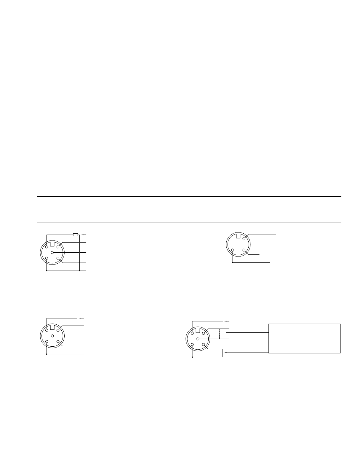
PIN connector standard wiring
NOT USED
CX2 wire transmitter
TURN FLOW RELAY CONTA CT FROM A
SWITCH TO A PULSE OUT BY EXTERNALLY
CONECTING A 2K - 10K Ω PULL UP RESISTOR
FROM POWER SUPPLY TO ONE FLOW RELAY
CONTACT AND CONNECTING THE OTHER
FLOW RELAY CONTAC TO SUPPLY GROUND.
CONFIGURATION:
1: +24 VDC POWER SUPPLY
2: 4-20 mA FLOW SIGNAL OUT
3: SUPPLY GROUND
4: FLOW RELAY CONTA CT
BROWN
1
2
2
GRAY
5
4
3
BLACK
BLUE
[FLOW ONLY]
BROWN
1
5
3
GRAY
4
BLACK
BLUE
+24 VDC SUPPLY
FLOW RELAY CONTACT
FLOW RELAY CONTACT
SUPPLY GROUND
CP
WIRING
4-20 mA FLOW SIGNAL OUT
+24 VDC SUPPLY
FLOW SIGNAL PULSE OUTPUT
SUPPLY GROUND (REDUNDANT)
SUPPLY GROUND
CONFIGURATION:
1: +24 VDC POWER SUPPLY
2: NOT USED
3: SUPPLY GROUND
4: SUPPLY GROUND
5: FLOW SIGNAL PULSE OUTPUT
NOTE: THERE IS AN INTERNAL 10K Ω PULL-UP
Totalizer with pulse output
PIN CONFIGURATION:
1: +24 VDC POWER SUPPLY
2: 4-20 mA FLOW SIGNAL OU
3: POWER SUPPLY GROUND
4: FLOW RELAY CONTACT
BROWN
*
1
2
5
3
GRAY
4
BLACK
BLUE
Figure 2a: Pin diagrams
8 Series CP CN CT CX User's Manual
Page 9
BROWN
LOAD
T
8: TEMP RELAY CONTACT
T
SUPPLY GROUND
BROWN
WHITE
BLUE
1
PINK
7
6
8
2
RED
3
5
4
GRAY
YELLOW
GREEN
CT (ow and temperatue) wiring
4 mA to 20 mA FLOW SIGNAL OUT
+24 V DC SUPPLY
TEMP RELAY CONTACT
4 mA to 20 mA TEMP SIGNAL OUT
TEMP RELAY CONTACT
FLOW RELAY CONTACT
FLOW RELAY CONTACT
SUPPLY GROUND
PIN CONFIGURATION:
1: +24 V DC POWER SUPPLY
2: 4 mA to 20 mA FLOW SIGNAL OU
3: POWER SUPPLY GROUND
4: FLOW RELAY CONTACT
5: FLOW RELAY CONTACT
6: 4 mA to 20 mA TEMP SIGNAL OUT
7: TEMP RELAY CONTACT
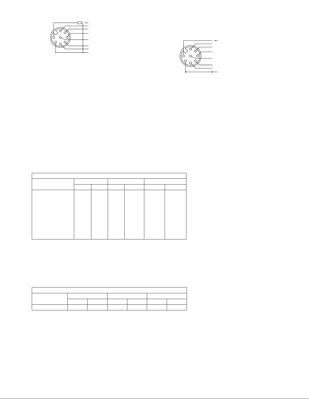
Figure 2b: Pin diagrams
WHITE
1
7
8
6
2
3
5
4
YELLOW
GREEN
4 mA to 20 mA FLOW SIGNAL OU
+24 V DC SUPPLY
BLUE
TEMP RELAY CONTACT
PINK
4 mA to 20 mA TEMP SIGNAL OUT
RED
TEMP RELAY CONTACT
GRAY
FLOW RELAY CONTACT
FLOW RELAY CONTACT
CT wiring
5. Operation
The CoolPoint® inline owmeter utilizes the vortex shedding principle. The uid strikes a bluff body, generating
vortices (eddies) that move downstream. The vortices form alternately, from one side to the other. A piezoelectric
sensor housed in a sensor tube directly downstream of the bluff senses the pressure zones created by the
vortices. The sensor generates a frequency directly proportional to the vortices (ow). The pulses are then
amplied by the circuit board and converted to a 4 mA to 20 mA output, which is also linear with ow. Flow is
displayed on the LEDs in either GPM or LPM. Selection of the preferred units of measure is made by using the
SET push button. A solid-state relay can also be set for a low-ow alarm, typically from 15 % to 90 % of full-scale
ow. The relay can be congured to be either NC (normally-closed) or NO (normally-open), or for a pulse output.
Flow Set Point Ranges
Meter Size
6.35 mm (1/4 in)
9.53 mm (3/8 in)
12.7 mm (1/2 in)
19.05 mm (3/4 in)
25.4 mm (1 in)
38.1 mm (1 in)
50.8 mm (2 in)
76.2 mm (3 in)
101.6 mm (4 in)
Setpoint Min. Setpoint Max. Hysteresis
GPM LPM GPM LPM GPM LPM
0.4
0.6
1.2
7.5
15
30
40
80
1.5
2.3
4.5
3
11
30
56
113
151
302
3
6
12
22.5
45
90
180
280
560
12
23
45
85
170
341
682
1059
2119
0.1
-
1.2
2.5
5
10
15
30
0.4
-
5
9
18
37
57
114
-
-
CT owmeters can combine temperature measurement with the ow-measuring feature. An internal temperature
sensor, housed in a small thermowell downstream of the ow sensor, measures the liquid temperature.
Temperature can be displayed in either degrees Fahrenheit or Celsius, and is selected by using the SET push
button. There is an independent 4 mA to 20 mA output proportional to temperature and an independent solidstate relay that can be congured as a high temperature alarm. The relay state (NC or NO) is the same as that
selected for ow alarm. The user can select either ow or temperature to be displayed on the LEDs by using the
MENU push button.
Temperature Set Point Ranges
Meter Size
Setpoint Min. Setpoint Max. Hysteresis
°F °C °F °C °F °C
All CT Models 35 1 200 93 4 2
Cleaning: These meters do not require any special cleaning of the external surfaces. If cleaning is deemed
necessary, strong solvents, detergents, or chemicals should not be used. A damp cloth may be used to wipe off
dirt or debris.
9Operation
Page 10

6. Setup And Configuration
Factory Default Settings
Flow Units: GPM
Set Point: 00.0. NO/NC is set to NC. Flow averaging lter set to F 08.
Temperature Units: °F
6.1. Initial Power Up
Upon supplying the initial DC power, the unit goes into a set-up mode. First, it will energize the LED display,
showing that all segments of the display functions (8.8.8. is displayed), along with the GPM/LPM LEDs. Then it
will display the rmware revision by stating the revision (4.5P for example). Then nally, it will go into the run
mode and give the ow rate (or if no ow, 00.0).
When a ow alarm occurs, the second LED (either GPM or LPM) will blink as a visual indicator. Please note
the solid LED indicates engineering units of the display and blinking indicates a ow alarm. One of the two
LEDs is lit all the time. Use the SET push button to toggle between the two. If ow is available, the GPM and
LPM ow rates will be displayed (again the LPM ow rate is greater than the GPM).
6.2. Model CT
In addition to the above-mentioned LEDs, there are two more individual LEDs for temperature – °F and °C.
If the meter is displaying ow, these LEDs are off. Use the MENU push button to toggle between “ow” and
“temperature” displays.
When the “temperature” display is selected, the GPM and LPM LEDs turn off and either the °F or the °C LED
lights up. Use the SET push button to toggle between °F and °C.
Flow Alarm - If a low-ow alarm occurs while the meter is displaying temperature, both GPM and LPM LEDs
start blinking. If the meter is in “ow” display mode, the °F and °C LEDs remain off and either the GPM or LPM
LED blinks.
Temperature Alarm – If a high-temperature alarm occurs while the meter is displaying ow, both °F and °C
LEDs start blinking. If the meter is in “temperature” display mode, both the GPM and LPM LEDs remain off,
and either the °F or °C LED blinks.
6.3. Configuring the solid state relay as alarm output:
Step 1: Make sure the meter is in “ow” display mode. The MENU push button is used to toggle between the
“ow” and “temperature” displays. When in “ow” mode, either the GPM or the LPM LED lights up
(both °F and °C LEDs will be off).
Step 2: Press and hold MENU.
Step 3: “FLo” is displayed, followed by either “PUL” (for pulse output) or “ALA” (for alarm output).
Step 4: Release the MENU push button.
Step 5: If “ALA” is displayed, press the SET push button.
Step 6: If “PUL” is displayed, use the MENU push button to change it to “ALA”, then press the SET button.
Step 7: The 3-digit value that is displayed is the alarm set point (as stored in the memory).
Step 8: Use the MENU button to change the alarm set point, if needed.
Note
When MENU is pressed once, the display increments to the next value. If the MENU button is held down, the
display will initially increment slowly, then increment more quickly until the maximum allowed set point is
reached. It will then roll over to 0 and start from the minimum set point again. Please refer to Table 1 for the
range of acceptable ow set points for each owmeter size.
When the set point is 0, the ow alarm is disabled.
Step 9: Press the SET push button to store the new set point in the memory.
Step 10: The LED then displays either “nc” (normally-closed) or “no” (normally-open). This is the state of the
relay when there is no ow alarm.
10 Series CP CN CT CX User's Manual
Page 11

Step 11: Use the MENU push button to toggle between “nc” and “no”.
Step 12: Use the SET push but ton to store the new relay conguration in memory.
6.4. Alarm Relays and Pulse Output
Both CP and CT models can be congured by the user to transmit either a ow alarm signal or a scaledpulse output. An internal solid-state relay (SSR) is shared between the ow alarm and pulse output.
Model CT has an additional SSR (independent of ow) for transmitting the temperature alarm.
The user menu is entered by pressing (and holding) the MENU push button. In this mode, all subsequent
selections must be made within 5 seconds of each other. A period of inactivity (not touching the push buttons)
longer than 5 seconds results in the meter’s reverting back to normal run mode, without storing the new
selection in the memory.
Note
The “LSP” and “HSP” relay contacts are independent of each other and can be set to “nc” or “no” for the ow
alarms. When either or both of the alarms are on, the alarm LED will blink.
6.5. Configuring the Solid State Relay as Pulse Output:
In order to congure the owmeter for scaled-pulse output, proceed as follows:
Step 1: Make sure the meter is in “ow” display mode. The MENU push button is used to toggle between the
“ow” and “temperature” displays. When in “ow” mode, either the GPM or the LPM LED lights up
(both °F and °C LEDs will be off).
Step 2: Press and hold MENU.
Step 3: “FLo” is displayed, followed by either “PUL” (for pulse output) or “ALA” (for alarm output).
Step 4: Release the MENU push button.
Step 5: If “PUL” is displayed, press the SET push button.
Step 6: If “ALA” is displayed, use the MENU push button to change it to “PUL”, then press the SET button.
6.5.1. Pulse Output
There is an output pulse proportional to ow “rate” as well. The pulse output always indicates ow in
GPM. It is driven by an internal solid-state relay with a 10K pull-up resistor to supply voltage (pulse width
= 3 ms). It should be noted that the pulse output represents instantaneous ow rate, not an averaged
value. Therefore, ow jitter may be present when an external rate indicator is used, unless the indicator is
capable of ltering or signal averaging.
The totalizer resolution and the corresponding ow rate pulse output depend on the full-scale setting of
the owmeter, as follows:
6.6. Configuring the Temperature Alarm
Only model CT can be congured by the user to transmit a temperature alarm. An internal solid-state relay
(independent of ow) is used as a “high alarm” for temperature, meaning that the alarm signal is transmitted
when the temperature set point is exceeded.
In order to congure the temperature alarm output, proceed as follows:
Step 1: Make sure the meter is in “temperature” display mode. The MENU push button is used to toggle
between the “ow” and “temperature” displays. When in “temperature” mode, either the °F or the °C
LED lights up (both GPM and LPM LEDs will be off).
Step 2: Press and hold MENU.
Step 3: “t” is displayed, followed by “AL”.
Step 4: Release the MENU push button.
Step 5: The 3-digit value that is displayed is the alarm set point (as stored in the memory).
11Setup And Conguration
Page 12

Step 6: Use the MENU button to change the alarm set point, if needed.
Note
When MENU is pressed once, the display increments to the next value. If the MENU button is held down, the
display will initially increment slowly, then increment more quickly until the maximum allowed set point is
reached. It will then roll over to 0 and start from the minimum set point again. Please refer to Table 2 for the
range of acceptable temperature set points.
When the set point is 0, the temperature alarm is disabled.
Step 7: Press the SET push button to store the new set point in the memory.
Note
The state of the SSR (“nc” - normally-closed) or (“no” - normally-open) is the same as the ow alarm relay,
and can only be changed in the ow alarm menu, regardless of whether the meter is congured for ow
alarm or ow pulse output. In other words, in order to select “no” or “nc” for temperature alarm relay, you must
repeat Steps 1 through 12 under “Conguring the Flow Alarm”. Later, if the meter is re-congured for scaledpulse output (ow), it does not affect the temperature relay state.
12 Series CP CN CT CX User's Manual
Page 13
6.7. Configuring Response Time in Filter Mode:
1 SEC/DIV
The response time for all models (except E4 or D2) can be congured by the user in the range of 0.9 s to
7.5 s (63 % step response). This is achieved by adjusting the “ltering” array size. Slower response typically
provides a more steady output signal, as the instantaneous ow variation (dependent on pump, piping, etc.) is
averaged out.
It should be noted that the response time refers to the D/A (analog 4 mA to 20 mA) output of the owmeter.
The LED display has a slower update rate.
In order to set the response time, proceed as follows:
Step 1: Make sure the meter is in “ow” display mode.
Step 2: Press and hold the MENU button until “Flo” is displayed.
Step 3: Release the MENU button.
Step 4: Depending on the output mode, either “PUL” or “ALA” will be displayed.
Step 5: After approximately 5 seconds “FLt” will be displayed.
Step 6: When “FLt” is displayed, press the SET button.
Step 7: The current lter setting will be displayed (2, 4, 8, 16, or 32 samples averaged to produce the output).
The letter “F” will be a prex to the lter value.
Response time for each setting is as shown in the table:
Response Time vs.
Filter Value
Filter
Value
2
4
8
16
32
Response
Time (S)
0.9
1.4
2.3
4
7.5
Step 8: To change the lter array size, press and release MENU. Alternately, you can press and hold the
MENU button and see the values scroll.
Step 9: When the desired lter size is selected, press the SET button.
Step 10: After the lter size is changed, the meter will reboot itself for the changes to take effect.
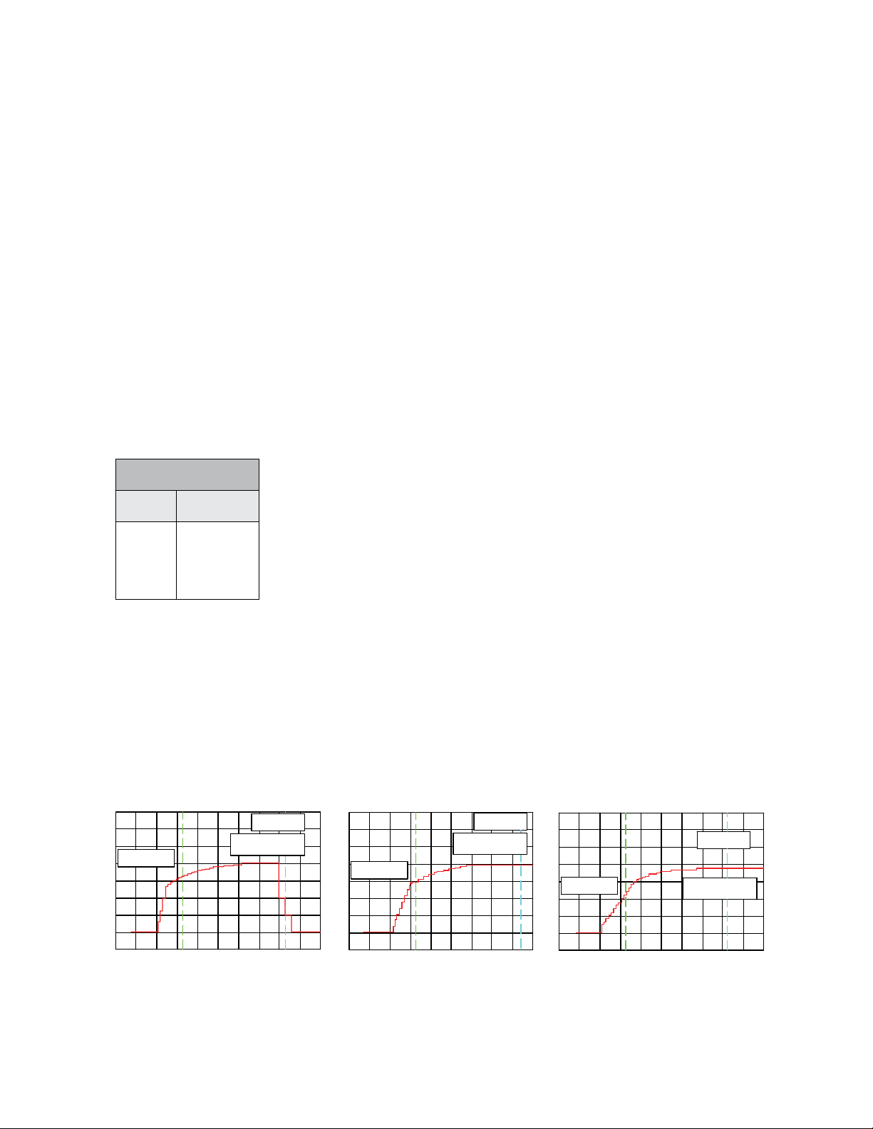
6.8. Step Response Graphs for Various Filter Settings
The following graphs show some examples of the step-response behavior of the meter for various lter
settings. The output shown is the 4 mA to 20 mA ow signal going from zero to full-scale ow, through a 250Ω load resistor (no ltering on the analog signal as shown). It is recommended that the user utilizes a lter
component (e.g., a 0.1 °F capacitor across the load resistor) after installation.
1 SEC/DIV
FLT = 4
1 VOLT/DIV
1 VOLT/DIV
Figure 3: Step-response behavior graphs
FLT = 8
1 VOLT/DIV
1 SEC/DIV
FLT = 16
13Setup And Conguration
Page 14

7. Maintenance/Repair
Upon nal installation of the Series CP/CN/CT/CX, no routine maintenance is required. The Series CP/CN/CT/CX
is not eld serviceable and is not possible to repair the unit. Field repair should not be attempted and may void
warranty.
8. Warranty/Return
Refer to “Terms and Conditions of Sale” in our catalog and on our website. Contact customer service to receive
a Return Materials Authorization (RMA) number before shipping the product back for repair. Be sure to include a
brief description of the problem plus any additional application notes.
9. FCC Compliance
This device complies with part 15 of the FCC Rules. Operation is subject to the following two conditions: (1) This
device may not cause harmful interference, and (2) this device must accept any interference received, including
interference that may cause undesired operation. Changes or modications not expressly approved by the party
responsible for compliance could void the user’s authority to operate the equipment.
Note: This equipment has been tested and found to comply with the limits for a Class A digital device, pursuant to
part 15 of the FCC Rules. These limits are designed to provide reasonable protection against harmful interference
when the equipment is operated in a commercial environment. This equipment generates, uses, and can radiate
radio frequency energy and, if not installed and used in accordance with the instruction manual, may cause
harmful interference to radio communications. Operation of this equipment in a residential area is likely to cause
harmful interference in which case the user will be required to correct the interference at his own expense.
CAN ICES-003(A) / NMB-003(A)
This Class A digital apparatus complies with Canadian ICES-003
Cet appareil numérique de la classe A est conforme à la norme NMB-003 du Canada
14 Series CP CN CT CX User's Manual
Page 15

®
dwyer-inst.com
©Copyright 2024 Dwyer Instruments, LLC Printed in U.S.A. 9/24
Improving the world, one measurement at a time.
TM
UNIVERSAL
FLOW MONITORS
FR#: 444689-00 Rev. 2
 Loading...