

Page 1
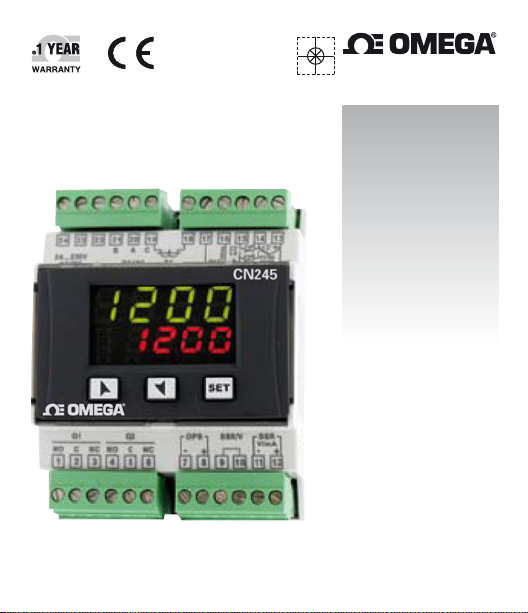
User’s Guide
Shop online at
omega.com
e-mail: [email protected]
For latest product manuals:
www.omegamanual.info
MADE IN ITALY
®
CN245
Controller
Page 2

omega.com [email protected]
U.S.A.: Omega Engineering, Inc., One Omega Drive, P.O. Box 4047
Stamford, CT 06907-0047 USA
Canada: Toll-Free: 1-800-826-6342 (USA & Canada only)
Mexico/ Tel: 001 800-099-0420 (Mexico only)
Latin Tel: 001-203-359-7577 (Outside Mexico)
America: Fax: 001-203-968-7290 e-mail: [email protected]
Web: mx.omega.com
China: Hotline: (+86) 800 819 0559, (+86) 400 819 0559
France: Freephone: 0805 541 038 (France only)
Germany/ Freephone: 0800 826 6342 (Germany only)
Austria: Tel: +49 (0)7056-9398-0 Fax: +49 (0)7056-9398-29
Italy: Freephone: 800 906 907 (Italy only)
Netherlands: Freephone: 0800 099 33 44 (Netherlands only)
Benelux Tel: +31 070 770 3815 Fax: +31 070 770 3816
Spain: Freephone: 800 900 532 (Spain only)
United Freephone: 0800 488 488 (United Kingdom only)
Kingdom: Tel: +44 (0)161 777 6611 Fax: +44 (0)161 777 6622
Servicing North America:
Toll-Free: 1-800-826-6342 (USA & Canada only)
Customer Service: 1-800-622-2378 (USA & Canada only)
Engineering Service: 1-800-872-9436 (USA & Canada only)
Tel: (203) 359-1660 Fax: (203) 359-7700
e-mail: [email protected]
Tel: (514) 856-6928 Fax: (514) 856-6886
e-mail: [email protected] Web: www.omega.ca
Servicing Mexico and Latin America:
Servicing Asia:
Servicing Europe:
e-mail: [email protected] Web: www.omega.de
Page 3

Summary
1 Safety guide lines ...................................................................................................................5
2 Model identication ..............................................................................................................6
3 Technical Data ........................................................................................................................6
3 .1 General data ..................................................................................................................6
3 .2 Hardware data .............................................................................................................. 6
3 .3 Soft ware data ................................................................................................................7
4 Dimensions and Installation ...............................................................................................8
5 Electrical wirings ....................................................................................................................9
5.1 Wiring diagram .............................................................................................................9
6 Display and Ke y Functions .................................................................................................15
6 .1 Numeric Indi cators (Display) ...................................................................................15
6 .2 Meaning o f Status Lights (Led) ...............................................................................15
6.3 Keys ................................................................................................................................ 16
7 Controller Functions ........................................................................................................... 16
7.1 Modi fying Main Setpoi nt and Alarm Setpoint Values ..................................... 16
7.2 Auto-Tuning .................................................................................................................17
7.3 Manual Tuning ............................................................................................................17
7.4 Automatic Tuning .......................................................................................................17
7.5 Sof t-Start .......................................................................................................................17
7.6 Automa tic / Manual Regulation fo r % Output Control ................................... 18
7.7 Pre- Programmed Cycle .............................................................................................19
7.8 CN-Cong-Module (optional) ................................................................................ 20
8 Latch on func tions .............................................................................................................. 22
8 .1 Loop Break Ala rm On Current Trasformer .......................................................... 23
8 .2 Digital Im put Functions ........................................................................................... 24
8 .3 D ual Action Heating-Cooling ................................................................................ 25
9 Serial Communication .......................................................................................................28
10 Enter Cong uration parameters ..................................................................................... 34
10.1 Loading default values ............................................................................................ 35
11 Table of congu ration parameters ................................................................................ 36
12 Alarm I ntervention Modes ................................................................................................ 53
13 Table of Anomaly Signals.................................................................................................. 58
14 Summary of Conguration parameters ....................................................................... 59
User manual - CN245 - 3
Page 4

Sommario
1 Norme di sicu rezza ............................................................................................................. 63
2 Identicazione del modello ..............................................................................................64
3 Dati tecnici ............................................................................................................................ 64
3 .1 Caratteristich e generali ........................................................................................... 64
3 .2 Caratteris tiche hardware ........................................................................................ 64
3 .3 Caratteris tiche software .......................................................................................... 65
4 Dimensioni e installazione ...............................................................................................66
5 Collegamenti elettrici......................................................................................................... 67
5.1 Schema di collegamento ......................................................................................... 67
6 Funzione dei v isualizzatori e tasti ................................................................................... 73
6.1 Indicatori numerici (display) ................................................................................... 73
6 .2 Signicato de lle spie di stato (led) ......................................................................... 73
6. 3 Tasti ................................................................................................................................74
7 Funzioni del regolatore ......................................................................................................74
7.1 Modi ca valore setpoint princi pale e setpoint di allar me...............................74
7.2 Auto-tune..................................................................................................................... 75
7.3 Lancio dell’AutoTuning “Manuale” .......................................................................75
7.4 Tuning “Automatico” ................................................................................................75
7.5 Sof t Start ...................................................................................................................... 76
7.6 Regol azione automatico / manua le per controllo % uscita .......................... 76
7.7 Ciclo pre-programmato........................................................................................... 77
7.8 CN-Cong-Module .................................................................................................... 78
8 Funzione L ATCH ON ............................................................................................................ 80
8 .1 Loop Break Ala rm su TA (Trasformatore Am perometrico) ............................. 81
8 .2 Funzioni da Ingresso digitale ................................................................................ 83
8 .3 Funzionamento in doppia azione (caldo-freddo) ............................................84
9 Comunicazione Seriale ...................................................................................................... 87
10 Accesso alla congurazione ............................................................................................. 93
10.1 Caricamento valori di default ................................................................................ 94
11 Tabella parametri di congurazione .............................................................................95
12 Modi d ’intervento allarme ............................................................................................... 11 3
13 Tabella segnalazioni anomalie ......................................................................................117
14 Promemoria congurazione ...........................................................................................118
4 - CN245 - User manual
Page 5

Introduction
Thank you for choosing an Omega controller.
Controller CN245 is specically conceived for application on control panels with
DIN rail mounting.
Omega make s available in a single device all the options relevant to sensor input
and actuators command, in addition to the extended power range 24 .. 230 Vac/
Vdc. With 18 sensors to select and outputs congurable as relay, Ssr command,
4 .. 20 mA and 0 .. 10Volt, th e user or retailer can r educe warehouse sto ck by rationalising investment and device availability. The series is completed with models
equipped with serial communication RS485 Modbus RTU and with a loading
control function via the amperometric transformer. The conguration is further
simplied by the CN-Cong-Modules which are equipped with internal battery
and therefore don’t require cabling to p ower the controller.
1 Safety guide lines
Read carefully the safety guidelines and programming instructions contained in
this manual before using/connecting the device.
Disconnect power supply before proceeding to hardware settings or electrical
wirings.
Only qualied personnel should be allowed to use the device and/or service it
and in accordance to technical data and environmental conditions listed in this
manual.
Do not dispose electric tools together with household waste material. In
observance European Directive 2002/96/EC on waste electrical and electronic
equipment and its implementation in accordance with national law, electric tools
that have reached the end of the ir life must be collec ted separately and returned
to an environmentally compatible recycling facility.
User manual - CN245 - 5
Page 6

2 Model identication
Power supply 24 .. 230 Vac/Vdc +/- 15% 50/60Hz – 5,5VA
CN245-R1R2F3C4 2 Relays 5A + 1 Ssr/V/mA + Rs4 85 +T.A.*
* Model with
current transformer input for “Loop Break Alarm” function.
3 Technical Data
3.1 General data
Displays
Operating
temperature
Sealing
Material PC ABS UL94VO self-exstinguishing
Weight 165 g
4x0.40 inch displays
4x0.30 inch displays
Temperature 0-45 °C
Humidit y 35..95 uR%
IP65 front panel
IP20 box and terminals
3.2 Hardware data
AN1 Congurable via software
Input Thermocouple type K , S, R,
J. Automatic compensation of cold
Analogue
imput
Relay
output
6 - CN245 - User manual
junction from from 0°C to 50°C.
Thermoresistance: PT100, PT500,
PT1000, Ni100, PTC1K, NTC10K.
Linear: 0-10V, 0-20 or 4-20mA,
0-40mV, amperometric transformer T.A. 50mA 1024 points
Potentiometers: 6 K, 150 K.
2 relays Congurable for
command or alarm.
Tolerance (25 °C) +/-0.2% ±1 digit
(F.s.) for thermocouple input,
thermo resistance and V / mA .
Cold junction accurac y 0,1°C/°C.
Impedance:
0-10 V : Ri>11 0K
0-2 0 mA: Ri<5
4-2 0 mA: Ri<5
0-40 mV: Ri>1M
Contacts 5A/250V~Resistite loads
Page 7

SSR 12V 30mA
Congurable:
0-10 V with 9500 points +/-0.2%
(F. s. )
0-2 0 mA with 7500 points +/-
0.2% (F.s.)
4-2 0 mA with 6000 points +/-
0.2% (F.s.)
SSR/V/mA
output
1 linear 0/4..20mA /SSR/0..10Volt
Congurable as command or retransmission of setpoint/process
3.3 Software data
Regulation
algorithms
Proportional band 0...9999 °C or °F
Integral time 0,0.. .999,9 sec. (0 e xcludes integral func tion)
Derivative time 0,0...999,9 sec. (0 excludes derivative function)
Controller
functions
ON - OFF with hysteresis.
P, P.I., P.I.D., P.D. with proportional time.
Manual or automatic Tuning, congurable alarms, protection of command and alarm setpoints, activation of
functions via digital input, preset cycle with Start / Stop.
User manual - CN245 - 7
Page 8
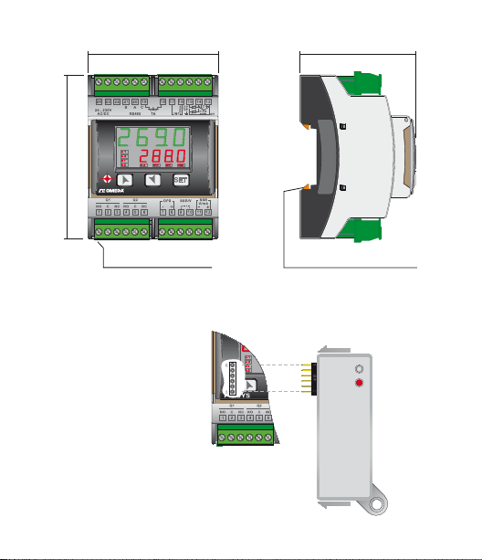
4 Dimensions and Installation
90 mm
72 mm
CN243
64 mm
Extractable terminal blocks
Morsettiere Estraibili
8 - CN245 - User manual
Din rail mounting guide EN50022
Attacco a guida DIN EN50022
CN-CONFIG-MODULE
(optional)
Page 9
5 Electrical wirings
Although this controller has been designed to resist noises in an industrial environment, please notice the following safety guidelines:
• Separatecontrollinesfromthepowerwires.
• Avoid the proximity of remote control switches, electromagnetic meters,
powerful engines.
• Avoidtheproximityofpowergroups,especiallythosewithphasecontrol.
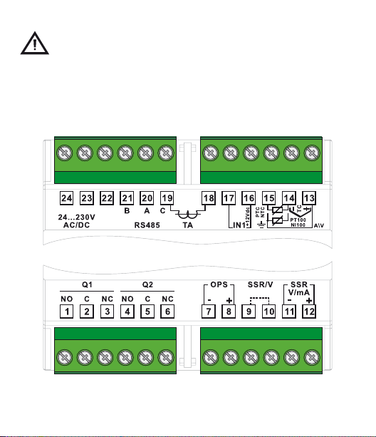
5.1 Wiring diagram
User manual - CN245 - 9
Page 10
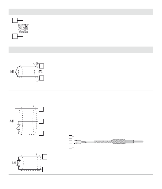
Power supply
24
15
23
SUPPLY
24..230
Vac/dc
Switching supply with extended range
24 .. 230 Vac/dc ±15% 50/60Hz – 5,5VA
(galvanic isolated)
AN1 analogue imput
Shield/Schermo
AI1
Shield/Schermo
Rosso
Red
Bianco
AI1
PT/NI100
White
Rosso
Red
Shield/Schermo
AI1
PTC/NTC
10 - CN245 - User manual
For thermocouples K , S, R, J.
• Complywithpolarity.
13
• Forpossibleextensions,useacompensatedwire
TC
and terminals suitable for the thermocouples used
(compensated).
14
• Whenshieldedcableisused,itshouldbegrounded
at one side only.
For thermoresistances PT100, NI100.
• Forthethree-wireconnectionusewireswiththe
same section.
13
• Forthetwo-wireconnectionshort-circuitterminals1
and 3.
• Whenshieldedcableisused,itshouldbegrounded
14
at one side only.
• SelectinternaljumperJP3asinthegure.
15
14
13
RED/ROSSO
WHITE/BIANCO
14
15
RED/ROSSO
For thermoresistances NTC, PTC , PT500, PT1000 e
potentiometers.
When shielded cable is used, it should be grounded at
one side only to avoid ground loop currents.
Page 11
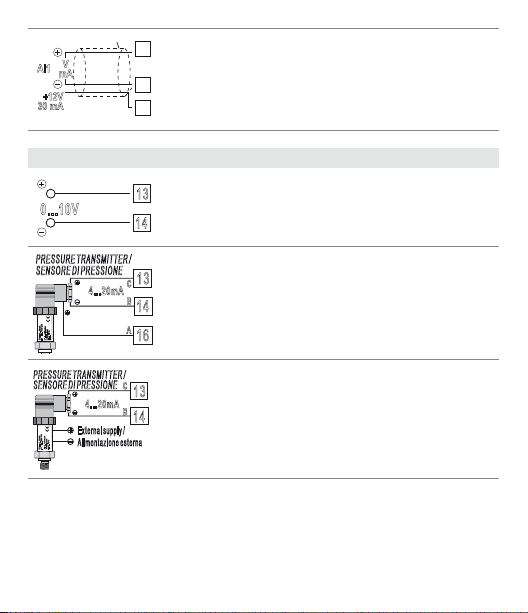
AI1
+12V
30 mA
mA
V
Shield/Schermo
13
For linear signals V / mA.
• Complywithpolarity.
14
• Whenshieldedcableisused,itshouldbegrounded
at one side only.
16
Example of connection for linear input Volt and mA
For signals 0 .. .10 V.
0...10V
13
14
Comply with polarity.
PRESSURE TRANSMITTER /
SENSORE DI PRESSIONE
P :0...100mbar
Pmax :3bar
T :0..70°C
OUT : 4...20mA
IN :9...33V DC
PRESSURE TRANSMITTER /
SENSORE DI PRESSIONE
P :0...100mbar
Pmax :3bar
T :0..70°C
OUT : 4...20mA
IN :9...33V DC
13
C
4...20mA
B
14
A
16
C
13
4...20mA
B
14
External supply /
Alimentazione esterna
For signals 0/4 .. .20 mA with three-wire sensor.
Comply with polarity:
A= Sensor output
B= Sensor ground
C= Sensor power supply (12Vdc / 30mA)
For signals 0/4 .. .20 mA with external power of sensor.
Comply with polarity:
A= Sensor output
B= Sensor ground
User manual - CN245 - 11
Page 12
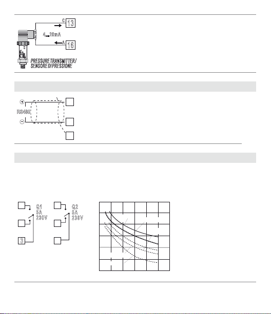
4...20mA
4
OUT : 4...20mA
IN :9...33V DC
P :0...100mbar
Pmax :3bar
T :0..70°C
PRESSURE TRANSMITTER /
SENSORE DI PRESSIONE
Serial input
Shield/Schermo
RS485
Relay Q1 - Q2 out put
1
Q1
5A
230V
2
3
12 - CN245 - User manual
C
13
For signals 0/4 .. .20 mA with two-wire sensor.
A
Comply with polarity:
16
A= Sensor output
C= Sensor power supply (12Vdc / 30mA)
21
RS485 Mo dbus RTU communication.
• Fornetworkswithmorethanveinstruments
20
supply in low voltage, preferably Vdc.
• Shieldmustnot be grounded (connect to pin 19)
19
Capacity:
• 5 A / 250 V~ for resistive loads, 10
• 20/2 A, 250 Vac, cosφ = 0.3, 10
4
Q2
5A
230V
5
6
200
100
operations)
50
20
10
Service life (x10
AC250V COS ø=0.4
5
DC30 V t=15ms
0
Life Curve
AC250V
DC30 V
AC125 V
2 3 4
1
Contact load current (A)
AC125V COS ø=0.4
DC30 V t=7ms
5
5
operations.
5
operations.
Page 13
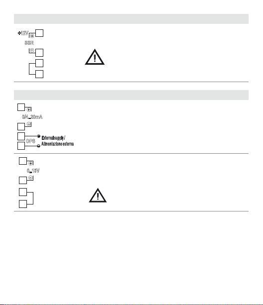
SSR output
9
12
+12V
12
SSR
11
10
mA / Volt output
0/4..20mA
11
8
OPS
7
12
0..10V
11
10
9
External supply /
Alimentazione esterna
SSR command 12V/30mA
Short-circuit pins 9 and 10 as in the gure to
use SSR output
Pins 11-1 2: linear output in mA congurable using parameters as command (Parameter
sion of process or setpoint (Parameter
Pins 7-8: optional external power supply for current
loop (max 24Vdc).
Linear output in Volt congurable using parameters
as command (Parameter
process or setpoint (Parameter
Short-circuit pins 9 and 10 as in the gure to
use linear output in Volt.
c.out
c.out
) or retransmission of
re tr.
).
User manual - CN245 - 13
) or retransmis-
re tr.
).
Page 14
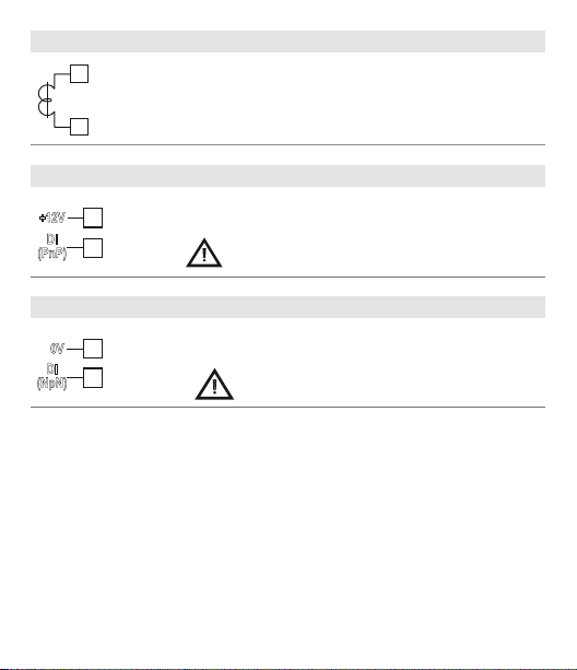
Current transformer input
18
TA
19
Digital Input 1
+12V
16
DI
17
(PnP)
Digital Input 2
0V
14
DI
15
(NpN)
14 - CN245 - User manual
• Input50mAforamperometrictransformer
• Samplingtime80ms
• Congurablebyparameters
Use of digit al input without T.A . input
Digital input according to parameter
Combined use of digital input and T.A. input
Digital input according to parameter
Short-circuit pins 16 and 17 as in the gure to
d Gt.i .
activate the digital input.
d Gt.i .
This combined use is possible only with
sensors TC, 0 .. 10V, 0/4 .. 20mA, 0 .. 40 mV.
Page 15
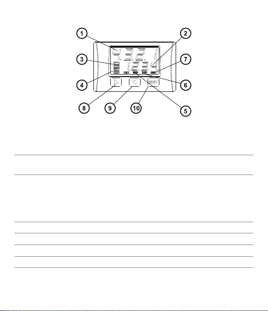
6 Display and Key Functions
6.1 Numeric Indicators (Display)
1
2
1234
1234
Normally displays the pro cess. During the conguration
phase, it displays the parameter being inserted.
Normally displays the setpoint. During the conguration
phase, it displays the parameter value being inserted.
6.2 Meaning of Status Lights (Led)
3 C1 C2
4 A1 A2 A3 ON when the corresponding alarm is on.
5 MAN ON when the “Manual” function is on.
6 TUN ON when the controller is running an “Autotune” cycle.
7 REM ON when the controller communicates via serial port.
ON when the output command is on.
C1 with relay/SSR/mA /Volt command or C1 (open) and C2
(close) for a motorised valve command.
User manual - CN245 - 15
Page 16
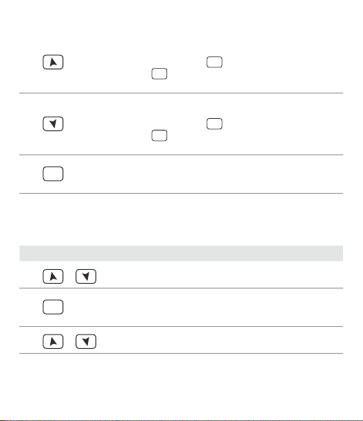
6.3 Keys
• Allowstoincreasethemainsetpoint.
• Duringthecongurationphase,allowstoslidethrough
8
parameters. Together with the
• Pressedafterthe
SET
key it allows to increase the alarm
SET
key it modies them.
setpoint.
• Allowstodecreasethemainsetpoint.
9
parameters. Together with the
• Pressedafterthe
SET
key it allows to de crease the alarm
• Duringthecongurationphase,allowstoslidethrough
SET
key it modies them.
setpoint.
• Allowstodisplaythealarmsetpointandrunstheautotuning
SET
10
function.
• Allowstovarythecongurationparameters.
7 Controller Functions
7.1 Modifying Main Setpoint and Alarm Setpoint Values
The setpoint value can be changed by keyboard as follows:
Press Display Do
1
or
SET
2
3
or
16 - CN245 - User manual
Value on display 2 changes.
Visualize alarm setpoint
on display 1 value being
inserted.
Value on display 2 changes.
Increases or decreases
the main setpoint.
Increases or decreases
the alarm setpoint value.
Page 17

7. 2 Auto-Tuning
Tuning procedure calculates the controller parameters and can be manual or
automatic according to selection on parameter 57 (
tunE
).
7. 3 Manual Tuning
Manual procedure allows the user greater exibility to decide when to update
P.I.D. algorithm work parameters. The procedure can be ac tivated in two ways:
• RunningTuningbykeyboard:
SET
Press
TUN led switches on and the procedure b egins.
•RunningTuningbydigitalinput:
Select
key until display 1 shows the writing
off
, press , display 2 shows on.
tun e
(commutation on front panel) TUN led switches on and at second activation
on parameter 61
switches o.
d Gt.i .
tunE
with display 2 showing
At rst activation of digital input
7.4 Automatic Tuning
Automatic tuning activates when the controller is switched on or when the
setpoint is modied to a value over 35%.
To avoid an overshoot, the treshold where the controller calculates new P.I.D.
parameters is determined by the setpoint value minus the “Set Deviation Tune”
(see parameter 58
To exit Tuning and keep P.I.D. values unchanged, press
shows the writing
TUN
led switches o and procedure nishes.
S.D. t u .
).
tun e
and display 2 shows on. Press , display 2 shows
SET
key until display 1
off
7. 5 Soft-Start
To reach the setpoint the controller can follow a gradient expressed in units
(example: Degree/Hours).
Enter the gradient on parameter 62
subsequent activation the controller uses Soft-Start function.
GrAd .
with chosen Units/Hours; only on
User manual - CN245 - 17
.
Page 18

If parame ter 59
0, after s witch-on and el apsing of the time set o n parameter 63, setp oint does not
follow the gr adient anymore, but it reaches nal setpoint with maximum power.
Autotuning does not work when Soft-Start is activated: otherwise if parameter
63
m a . ti .
start s when Soft-Start time is nished.
If parameter 57
Soft-Start nishes.
op.mo.
is set on
co nt.
and param eter 63
is dierent f rom 0 and parameter 57
tun e
is set on
man.
, the Autotuning can be started only when
tun e
m a . ti .
is set on
is dierent from
au to
, Autotuning
7.6 Automatic / Manual Regulation for % Output Control
This function allows to select automatic functioning or manual command of the
output percentage.
With parameter 60
1 First selection (
Pressing
Pressing
percentage using
procedure, select
returns to automatic mode.
2 Second selec tion (
enables the same f unctioning, but with two impor tant variants:
• Ifthereisatemporarypowerfailureorafterswitch-o,themanualfunctio-
ning as well as the previous output percentage value will be maintained at
restarting.
• If thesensorbreaks during automaticfunctioning, thecontroller movesto
manual mode while maintaining the output percentage command unchanged as generated by the P.I.D. immediately before breakage.
18 - CN245 - User manual
Au.ma.
en.
)
SET
key display 1 shows
key display shows
and . To return to automatic mode, using the same
Auto
EN. ST,
, can select two methods.
p.---
, while display 2 shows
Man.
; it is now possible to change the output
on display 2: led MAN switches o and functioning
)
Auto
.
Page 19
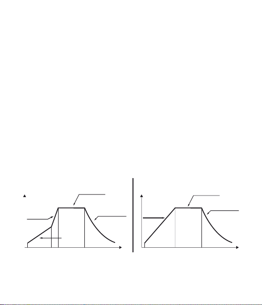
7.7 Pre-Programmed Cycle
The pre-programmed cycle function activates by setting
parameter 59
First selection (
oP.Mo
.
Pr. c y
):
the controller reaches setpoint1 basing on the gradient set on parameter 62
Gra d .
, then it reaches maximum power up to setpoint 2. When the process
reaches maximum power, this setpoint is maintained for the time set on
parameter 63
m a . ti .
On expiry, the command output is disabled and controller displays
Cycle starts at each activation of the controller, or via digital input if it is
enabled for this type of functioning (see parameter 61
Pr. c y
Second se lection (
):
start-up is decided only on activation of the digital input, according to the
setting of parameter 61
following gradient set in parameter 62
d Gt.i .
On start-up, controller reaches setpoint 1
Gra d .
When the process reaches this gradient, it is maintained for the time set on
paramete r 63
ler displays
First selection
Primo caso
Setpoint
Max. Power
Potenza
massima
Setpoint 2
Gradient
Gradiente
m a . ti .
stop
Setpoint 1
On expir y, command o utput is disabled and the control-
.
Second selection
Hold
Mantenimento
Natural cooling
Rareddamento
naturale
Secondo caso
Setpoint 1
Setpoint
Gradient
Gradiente
Pr. c y
or
Pc. SS.
d Gt.i .
).
Hold
Mantenimento
Natural cooling
Rareddamento
naturale
User manual - CN245 - 19
stop
TempoTime
on
.
Page 20

Variation (
Selecting
selection (
is lower than SET1, the device regulates the output power according to the
percentage selected on parameter 62
When the process is greater than SET1 or the time selected on parameter 63
M A . ti .
reaches SET2 the controller keeps it to innity.
If on param eter 59
ter 17
Starting the manual tune during the regulation on SET1, TUN led switches ON
only when the regulation pass to SET2.
The autotun ing (manual or automatic) wor ks only if SET2 is be ing regulated. If
the autotuning is launched during regulation on SET1 it do esn’t start until the
regulation pass to SET2.
S.S. cY.
):
S.S. cY.
(Soft Start Cycle) the controller will operate as per the rst
Pr. c y
) but with two important variations. If at starting the process
GrAd
.
is elapsed, it reaches maximum power up to SET2. When the process
oP.Mo.
is set
S.S. cY.
c. S.P.
: SET1 is no longer displayed and SET2 label becomes SE T.
it is possibl e to select
Hi d E
on parame-
7.8 CN-Cong-Module (optional)
Parameter s and setpoint valu es can be duplicate d from one controller t o another
using the CN-Cong-Module.
2 modes are available:
• Withthecontrollerconnectedtothepowersupply.
Insert CN-Cong-Module when the controller is o.
On activ ation display 1 shows
values ar e saved in the CN-Co ng-Module). By p ressing
Lo a d
, then conrm using
Controller loads the new value and restarts.
20 - CN245 - User manual
SET
mem o
key.
and display 2 sh ows
---
(only if the correct
key display 2 show s
Page 21
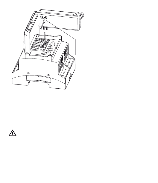
RED LIGHT: waiting for programming
GREEN LIGHT: done
LED ROSSO: accceso in programmazione
LED VERDE: programmazione eseguita
• Withthecontrollernotconnectedtopowersupply.
The CN- Cong-Modu le is equipped wit h an internal batter y with an autonomy of
about 1000 uses (2032 button bat tery, replaceable).
Insert the CN-Cong-Module and press the programming buttons.
When writing the parameters, led turns red and on completing the procedure it
changes to green. It is possible to repeat the procedure without any particular
attention.
Updating CN-Cong-Module
To update the CN- Cong-Module values, follow the procedure described on rst
mode, set ting display 2 to
----
so as not to load the parameters on controller1.
Enter conguration and change at least one parameter.
Exit conguration. Changes are stored automatically.
1
If on activation th e controller doe s not display
on the CN- Cong-Module , but it is possible to upd ate values.
mem o
it means no data h ave been saved
User manual - CN245 - 21
Page 22
8 Latch on functions
For use with input
K) and wi th linear input (0 .. 10 V, 0...40 mV, 0/4 .. 20 mA), it is possib le to associate
start v alue of the scale (p arameter 6
and value of end scale (parameter 7
sensor (parameter 8
It is also possible to x the point in which the controller will display 0 (however
keeping the scale range between
option by setting
If you set
set
u .OSt.
To enable the LATCH ON function select chosen conguration for parameter
2
LA t c
.
For the calibration proce dure refer to the following table:
Press Display Do
1
simultaneaously
2
3
2
The tuning procedu re starts by exitin g the conguration af ter changing the pa rameter.
22 - CN245 - User manual
P o t .1
(potentiometer 6 K) and
Lo L.i
) to the minimum p osition of the sens or
u P. L. i
La t c.
congured as
u .OSt.
or
u.Oin.
the virtual zero will reset after each activation of the tool; if you
the virtual zero remains xed once tuned.
u.Oin.
Exit parameters conguration. Display 2 shows
the writing
Set the value on minimum. Display shows
Lo w
Set the value to maximum.
The display shows
Lo L.i
in parameter 8
LA t c
.
Std .
and
Po t.2
(potentiometer 150
) to the maximum position of the
).
u P. L. i
) using the “virtual zero”
La t c
.
Place the sensor on
minimum operating
value (associated with
.
Lo L.i .
).
Place the sensor on
maximum operating
value (associated with
u p L.i .
).
To exit standard procedure press
“virtual zero” settings
place the sensor on the
Hi G H
.
zero point.
SET
. For
Page 23
Press Display Do
Max
Set the vir tual zero
value. Display shows
ui r t
SET
4
. NB: For selection
of
u.0in.
the procedure
in point 4 should be
followed on each reactivation.
To exit procedure press
SET
.
Min Zero
8.1 LoopBreakAlarmOnCurrentTrasformer
This function allows to measure load current and to manage an alarm during
malfunc tioning (with power in short circuit or always o ).
The current transformer connected to terminals 15 and 16 must be 50 mA (sampling time 80 ms).
• Set end scalevalueofthecurrent transformer inAmperes on parameter47
t.a.
• Set theinterventionthresholdoftheLoopBreakAlarmin Amperesonpara-
meter 48
L. b.a.d.
AL. 2
as
L.b.a.t.
L. b.a.
L.b.a.c.
on display 2 (alternatively with a command setpoint).
User manual - CN245 - 23
AL . 1
• Set the intervention delay time of the Loop Break Alarm on parameter 49
• Itispossibletoassociatethealarmwitharelaybysettingtheparameter
If a remote control switch or SSR remains closed, controller signals the fault
by showing
,
Page 24

If the power s tage remains ope n, or the load curre nt is lower than the value s et on
L.b.a.t.
, controlle r shows
absorbed during the closure phase of the power stage.
L. b.a.o.
on display. It is pos sible to display the curr ent
Press Display Do
SET
Press
until the writing
am.t.a.
This key enables to scroll on display 2 the output percentage,
SET
1
Setting on parameter 48
absorbed without generating the Lo op Break Alarm.
auto / man selection, setpoint
and alarms.
L.b.A.t.
the value 0 it is possible to visualize the current
appears on display 1
and display 2 shows the current in amperes (
The value is also maintained
when no current circulates on
the load.
t. a .
>0).
8.2 Digital Imput Functions
On CN245 model, digital input can be enabled by using parameters 59
and 61
d Gt.i .
•Parameter59
NB: When using this settings, parameter 61
2t.s .
2t. s .i .
3 t. s .i .
4 t. s .i
t. res .
p.c.s.s.
Setpoints values can be modied any time pressing
24 - CN245 - User manual
op.mo.
d Gt.i .
Switch two thresholds setpoint: with open contact CN245 regula-
tes on SET1; with closed contact regulates on SET2;
Switch two thresholds setpoint: setpoint selection is done by an
impulse on digital input;
Switch three thresholds setpoint by an impulse on digital input;
Switch four thresholds setpoint by an impulse on digital input;
Customized function;
Pre-programmed cycle (Par. 7.7 pag. 19).
is ignored.
op.mo.
SET
key.
Page 25

•Parameter61
NB: Settings on this parameter are available only if
selected on parameter 59
st.st.
rn.n.o.
rn.n.c.
L.c.n.o.
Lc.n . c.
tun e
a.ma.i.
a.ma.c.
NB: for the wiring connection of digital input see. (Par. 5.1 pag. 9)
Digital input functions are not available with sensors PT100 and Ni100 if also the
TA input is used.
d Gt.i .
co nt.
or
p r. cY.
are
op.mo.
Start / Stop; operating on digital input the controller switches
alternatively from start to stop;
Run N.O. Controller is in start only with closed input;
Run N.C. Controller is in start only with open input;
With closed input allows to lock the reading of sensors;
With open input allows to lock the reading of sensors;
Enables / disables Tuning function if parameter 57
lected as
man.
If parameter 60
switch from automatic to manual functioning;
If parameter 60
automatic mode if input is open or in manual mode if input is closed.
;
au.ma.
au.ma.
is selected as
is selected as
en.
en.
or
or
en .st.
en .st.
CN245 works in
tun e
is se-
controller
8.3 Dual Action Heating-Cooling
CN245 is suitable also for systems requiring a combined heating-cooling action.
Command output must be congured as Heating P.I.D. (
with a
P. b .
congured as
Command output must be connected to the actuator responsible fo r heat, while
the alarm will control cooling action.
Parameter s to congure for the Heating P.I.D. are:
Act. t.
P. b .
t.i
t.d.
t. c.
greater than 0), and one of the alarms (
co o L.
=
HEAT
: Heating proportional band;
: Integral time heating and cooling;
: Derivative time heating and cooling;
: Heating time cycle.
Command output type (Heating);
A L .1, AL. 2
Act. t.
=
HEAT
or
AL. 3
User manual - CN245 - 25
and
) must be
Page 26
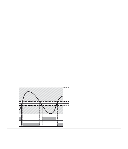
Parameters to congure for the Cooling P.I.D. are the following (ex: action asso -
ACTIVE
ACTIVE
SPV
PV
x = COOL
< 0
(HEAT)
COMMAND OUTPUT (HEAT)
ALARM OUTPUT (COOL)
ciated to alarm 1):
A L .1
=
coo L
P. b . M .
ou.d.b.
co.t.c.
Parameter
band of cooling basing on the formula:
Cooling proportional band =
This gives a proportional band for cooling which will be the same as heating
band if
Integral and derivative time are the same for both actions.
Parameter
actions. For systems in which the heating and cooling output must never be
simultaneously active a dead band (
versa an overlapping (
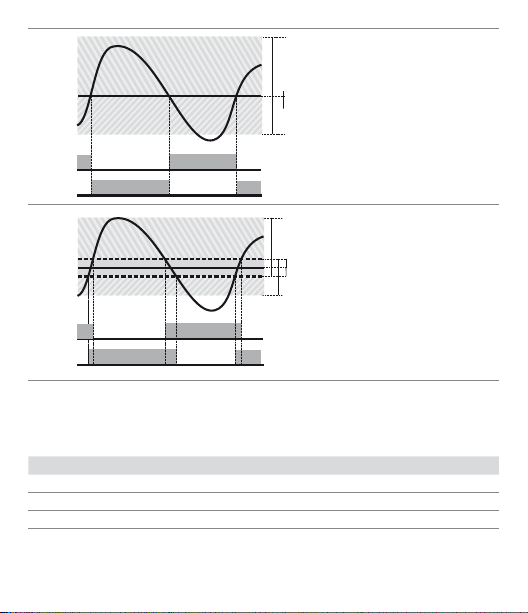
The following gure shows an example of dual action P.I.D. (heating-cooling)
with
1
Alarm 1 selection (Cooling);
: Proportional band multiplier;
: Overlapping / Dead band;
: Cooling time cycle.
p.b.m.
(that ranges from 1.00 to 5.00) determines the proportional
P. b .
P. b . M .
= 1.00, or 5 times greater if
ou.d.b.
determines the percentage overlapping between the two
ou.d.b.
> 0).
t.i .
= 0 and
t.d.
= 0.
x
P. b . M .
P. b . M .
= 5.00.
ou.d.b.
≤ 0) can be congured, and vice
26 - CN245 - User manual
Page 27
ACTIVE
ACTIVE
SPV
PV
x = COOL
x = COOL
< 0
= 0
(HEAT)
(HEAT)
COMMAND OUTPUT (HEAT)
ALARM OUTPUT (COOL)
COMMAND OUTPUT (HEAT)
ALARM OUTPUT (COOL)
SPV
PV
ACTIVE
ACTIVE
ACTIVE
ACTIVE
SPV
PV
x = COOL
x = COOL
x = COOL
< 0
= 0
> 0
(HEAT)
(HEAT)
(HEAT)
COMMAND OUTPUT (HEAT)
ALARM OUTPUT (COOL)
COMMAND OUTPUT (HEAT)
ALARM OUTPUT (COOL)
COMMAND OUTPUT (HEAT)
ALARM OUTPUT (COOL)
SPV
PV
ACTIVE
ACTIVE
SPV
PV
ACTIVE
ACTIVE
2
3
Parameter
Parameter
P. b . M .
co.t.c.
co o . f.
and the cool ing P.I.D. time c ycle
c o o . F.
Ai r
oi L
H2o
Once selected, parameter
however be changed.
has the same meaning as the heating time cycle
(cooling uid) pre-selects the proportional band multiplier
Cooling uid type
co.t.c.
basing on th e type of cooling uid:
Air 1.00 10
Oil 1.2 5 4
Water 2.50 2
co o . f.
, parameters
P. b . M . co.t.c
P. b . M ., oud.b.
and
User manual - CN245 - 27
t. c.
co.t.c.
can
Page 28

9 Serial Communication
CN245-R1R2F3C4, equipp ed with RS485, can re ceive and broadca st data via serial
communicat ion using MODBUS RTU p rotocol. The device c an only be congured
as a Slave. This function enables the control of multiple controllers connected to
a superv isory system (SCADA). Each controller responds to a master query only if
the query contains the same address as that in the parameter
The permitted addresses range from 1 to 254 and there must not be controllers
with the same address on the same line. Address 255 can be used by the master
to communica te with all the connec ted equipment (b roadcast mode), whi le with
0 all the devices receive the command, but no response is exp ected.
CN245 can introduce a delay (in milliseconds) in the response to the master
request. This delay must be set on parameter 72
is saved by the controller on EEPROM memory (100000 writing cycles), while the
setpoint s are saved with a delay of ten seconds after the last change.
NB: changes made to Words that are dierent from those reported in the following table can lead to malfunction.
se. d e.
Modbus RTU protocol features
bd . rt.
Selection on parameter 70
4.8 k
Baud-rate
Format 8, N, 1 (8 bit, no parit y, 1 stop)
Supported
functions
Looking at the table here below it is possible to nd all available addresses and
functions:
RO Read Only R/W Read / Write WO Write Only
28 - CN245 - User manual
4.800 bit/Sec.
9.6 k
9.600 bit /Sec.
19.2k
19.200 bit/Sec.
WORD READING (max 20 word) (0x03, 0x04)
SINGLE WORD WRITING (0x06)
MULTIPLE WORDS WRITING (max 20 word) (0x10)
:
28.8 k
38 .4 k
57.6 k
SL.Ad .
Each parameter change
28.800 bit/Sec.
38.400 bit/Sec.
57.600 bit/Sec.
Page 29

Modbus
Address
0 Device type RO EEPROM
1 Software version RO EEPROM
5 Slave address RO EEPROM
6 Boot version RO EEPROM
50 Automatic addressing WO 51 System code comparison WO -
500 Loading default values (write 9999) R/W 0
510 Setpoints storing time in eeprom (0-60 s) R/W 10
999 Process subjected to the visualization lter RO -
Process (degrees.tenths for temperature sensors;
1000
digits for linear sensors)
1001 Setpoint 1 R/W EEPROM
1002 Setpoint 2 R/W EEPROM
1003 Setpoint 3 R/W EEPROM
100 4 Setpoint 4 R/W EEPROM
1005 Alarm 1 R/W EEPROM
1006 Alarm 2 R/W EEPROM
1008 Setpoint gradient RO EEPROM
Relay status (0 = O, 1 = On):
Bit 0 = Relay Q1
Bit 1 = Relay Q2
1009
Bit 2 = Reser ved
Bit 3 = SSR
1010 Heating output percentage (0-10000) RO 0
1011 Cooling output percentage (0-10000) RO 0
Alarms status (0 = None, 1 = Active)
1012
Bit 0 = Alarm 1 Bit 1 = Alarm 2
Manual reset: write 0 to reset all alarms.
1013
In reading (0 = Not resettable, 1 = Reset table)
Bit 0 = Alarm 1 Bit 1 = Alarm 2
Description
Read
Reset
Only
value
RO -
RO 0
RO 0
WO 0
User manual - CN245 - 29
Page 30

Modbus
Address
Description
Error ags
Read
Only
Reset
value
Bit 0 = Eeprom writing error
Bit 1 = Eeprom reading error
Bit 2 = Cold junc tion error
Bit 3 = Process error (sensor)
1014
Bit 4 = Generic error
RO 0
Bit 5 = Hardware error
Bit 6 = L.B.A.O. error
Bit 7 = L.B.A.C. error
Bit 8 = Missing calibration data error
1015 Cold junction temperature (degrees.tenths) RO -
Start / Stop
1016
0 = Controller in STOP
R/W 0
1 = Controller in START
Lock conversion ON / OFF
1017
0 = Lock conversion o
R/W 0
1 = Lock conversion on
Tuning ON / OFF
1018
0 = Tuning o
R/W 0
1 = Tuning on
Automatic / manual selection
1019
0 = Automatic
R/W 0
1 = Manual
1020 T.A. current ON (Amp ere with tenths) RO -
1021 T.A. current OFF (Ampere with tenths) RO
1022 OFF LINE* time (milliseconds) R/W
* If va lue is 0, the contro l is disabled. I f dierent fro m 0, it is the max. ti me which can ela pse
betwee n two pollin gs before the controller goe s o-line. If it goes o-line, the controller
returns to Stop m ode, the control ou tput is disabled bu t the alarms are acti ve.
30 - CN245 - User manual
Page 31

Modbus
Address
1023 Instant Current (Ampere) R/W 0
1024 Digital Input State R/W 0
Synchronized Tuning for multizone system
0 = Tuning OFF (Normal operating of the regulator)
1 = Output command OFF
2 = Output command ON
1025
3 = Start Tuning
4 = End Tuning and output command OFF
(Write 0 for normal operating)
Process subjected to the visualization lter and
1099
decimal point selection
110 0 Process with decimal p oint selection RO
1101 Setpoint 1 with decimal point selection R/W EEPROM
110 2 Setpoint 2 with decimal point selection R/W EEPROM
110 3 Setpoint 3 with decimal point sele ction R/W EEPROM
110 4 Setpoint 4 with decimal point selection R/W EEPROM
110 5 Alarm 1 with decimal point selection R/W EEPROM
110 6 Alarm 2 with decimal point selec tion R/W EEPROM
110 8 Gradient Setpoint with decimal point selection RO EEPROM
110 9 Percentage heating output (0-1000) R/W 0
1110 Percentage heating output (0-100) RO 0
1111 Percentage cooling output (0-1000) RO 0
1112 Percentage cooling output (0-100) RO 0
2001 Parameter 1 R/W EEPROM
2002 Parameter 2 R/W EEPROM
2072 Parameter 72 R/W EEPROM
3000 Disabling serial control of machine** RO 0
** By w riting 1 on this word, the e ects of the writing a re cancelled on all the M odbus addresses
from 3001 to 3022. Cont rol therefore retu rns to the controller.
Description
Read
Reset
Only
value
R/W 0
RO
User manual - CN245 - 31
Page 32
Modbus
Address
3001 First word display 1 (ascii) R/W 0
3002 Second word display 1 (ascii) R/W 0
3003 Third word display 1 (ascii) R/W 0
3004 Fourth word display 1 (ascii) R/W 0
3005 Fif th word display 1 (ascii) R/W 0
3006 Six th word display 1 (ascii) R/W 0
3007 Seventh word display 1 (ascii) R/W 0
3008 Eighth word display 1 (ascii) R/W 0
3009 First word display 2 (ascii) R/W 0
3010 Second word display 2 (ascii) R/W 0
30 11 Third word display 2 (ascii) R/W 0
3012 Fourth word display 2 (ascii) R/W 0
3013 Fifth word display 2 (ascii) R/W 0
3014 Sixth word display 2 (ascii) R/W 0
3015 Seventh word display 2 (ascii) R/W 0
3016 Eight word display 2 (ascii) R/W 0
Word LED
Bit 0 = LED C1
Bit 1 = LED C2
Bit 2 = LED A1 Bit 3 = LED A2
3017
Bit 4 = LED A3
Bit 5 = LED MAN
Bit 6 = LED TUN
Bit 7 = LED REM
Word keys
(write 1 to command keys)
Bit 0 =
3018
Bit 1 =
SET
Bit 2 =
32 - CN245 - User manual
Description
Read
Only
R/W 0
R/W 0
Reset
value
Page 33

Modbus
Address
Word serial relay
3019
Bit 0 = Relay Q1
Bit 1 = Relay Q2
3020 Word SSR serial (0 = O, 1 = On) R/W 0
3021 Word output 0...10 V serial (0 .. 100 00) R/W 0
3022 Word output 4...20 mA serial (0 .. 10000) R/W 0
Relay state in case of o-line
(only if controlled by serial)
3023
Bit 0 = Relay Q1
Bit 1 = Relay Q2
Output st ate SSR / 0 .. 10 V / 4 .. 20 mA in case of o3024
line (only if controlled by serial)
(0 .. 10000)
Serial process. Setting parameter 54 it is possible
3025
to make averages on the remote process
4001 Parameter 1*** R/W EEPROM
4002 Parameter 2*** R/W EEPROM
4072 Parameter 72*** R/W EEPROM
*** Parameters m odied using seri al address 4001 to 4072 will b e stored on eeprom o nly after 10”
since last writ ing of one paramete r.
Description
Read
Reset
Only
value
R/W 0
R/W 0
R/W 0
R/W 0
User manual - CN245 - 33
Page 34
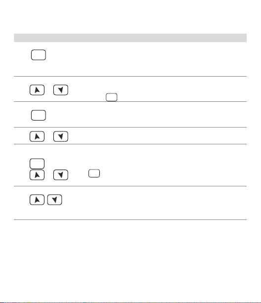
10 Enter Conguration parameters
For conguration parameters see: (Par. 11 pag. 36)
Press Display Do
Display 1 shows
with the 1st digit ashing,
while display 2 shows
PASS
.
1
for 3 seconds
SET
Changes ashing digit
2
or
and move to the ne xt one
using
Display 1 shows the rst
3
SET
to conrm
4
or
SET
5
or
parameter and display 2
shows the value.
Slide up / down through
parameters.
Increase or decrease displayed value by pressing
SET
and an arrow key.
End of conguration
6
simultaneously
34 - CN245 - User manual
parameter change.
The controller exits from
programming.
0.000
SET
key.
1234
Enter pa sword:
.
Enter new data which will
be saved on releasing the
keys. To change another
parameter return to
point 4.
Page 35
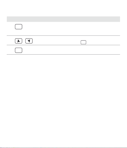
10.1 Loading default values
This procedure allows to res tore factory settings of the instrument.
Press Display Do
SET
1
for 3 seconds
2
3
SET
o
to conrm
Display 1 visualizes
with 1st digit blinking, while
display 2 shows
Change blinking digit and
move to the nex t one with
Device loads default settings.
PASS
0.000
.
Enter password:
SET
.
9999
Turn o and restar t
the instrument.
User manual - CN245 - 35
.
Page 36

11 Table of conguration parameters
The following table includes all parameters. Some of them will not be visible on
the models which are not provided with relevant Hardware data.
C.out Command Output
1
Command output type selection (see tables).
c. o1
Default (necessary for using process and setpoint retransmission
function with Volt / mA output)
c. o2
Command on relay output Q2
c.SS r
Command in tension for SSR
c. uA L.
Servo-valve command with open loop
c.4 . 2 0
4...20 mA command
c.0.20
c.0.10
0...20 mA command
0...10 V command
3
3
3
3
COMMAND ALARM 1 ALARM 2
CN245-R1R2F3C4
c. o1
c. o2
c.SS r
c. uA L.
c.4 . 2 0
c.0.20
c.0.10
3
D o not select if proces s retransmission func tion is used.
36 - CN245 - User manual
Q1 Q2 SSR
Q2 Q1 SSR
SSR Q1 Q2
Q1 (open)
Q2 (clo se)
4..20 mA Q1 Q2
0..20 mA Q1 Q2
0. .10 mV Q1 Q2
SSR -
Page 37

2 SEN. Sensor
Analogue input conguration/sensor selection
Tc.K
Tc- K (Default) -260 °C..1360 °C
Tc. s
Tc-S -40 °C ..1760 °C
Tc. r
Tc-R -40 °C..1760 °C
Tc. j
Tc-J -200 °C..1200 °C
Pt
Pt100 -200 °C..600 °C
P t1
Pt100 -200 °C..140 °C
ni
NI100 -60 °C..180 °C
n t c .1
NTC10K-β3435K -40 .. 125°C
n tc.2
NTC10K-OMEGA -40 .. 150°C
n tc.3
NTC2252-OMEGA -40 .. 150°C
Ptc
PTC1K -50 °C..150 °C
Pts
Pt500 -100 °C..600 °C
P t1 k
Pt1000 -100 °C..600 °C
0 .1 0
0..10 Vol t
0.20
0..20 mA
4.20
4..20 mA
0.4 0
0..40 mVolt
P o t .1
Potentiometer max 6 Kohm (Par. 8 pag. 22)
Po t.2
Potentiometer max 150 Kohm (Par. 8 pag. 22)
t.A.
50 mA secondary Current transformer
d . P. Decimal Point
3
Select type of visualized decimal point
0
Default
0.0
1 Decimal
0.00
2 Decimals
0.000
3 Decimals
User manual - CN245 - 37
Page 38

4 Lo. L.S . Lower Limit Setpoint
Lower limit selectable for setpoint
-999 .. +9999 [digit
u p .L. S. Upper Limit Setpoint
5
Upper limit selectable for setpoint
-999 .. +9999 [digit
4
] (degrees.tenths for temperature sensors), Default: 0.
4
] (degrees.tenths for temperature sensors),
Default: 1750.
Lo L.i Lower Linear Input
6
Range AN1 lower limit only for linear. Example: with input 4...20 mA this
parameter takes value associated to 4 mA
-999 bis +9999 [digit
u p .L.i . Upper Linear Input
7
4
], Default: 0.
Range AN1 upper limit only for linear. Example: with input 4...20 mA this
parameter takes value associated to 20 mA
-999 bis +9999 [digit
La t c. Latch On Funct ion
8
4
], Default: 1000.
Automatic setting of limits for linear inputs and potentiometers
(Par. 8 pag. 22)
di s .
Disabled (Default)
std .
Standard
u.0 st.
Virtual zero stored
u . 0i n
Virtual zero initialized
dYn .L
Allows to surpass lower and upper limits if on input there are
values out of 0/4..20mA or 0..10V.
38 - CN245 - User manual
Page 39

9 o . cA L. Oset Calibration
Value added / subtracted to process visualization (usually correcting the
value of environment temperature)
-999 .. +1000 [digit
-200.0 .. +100.0 (degrees.tenths for temperature sensors), Default 0.0.
10
G. cAL. Gain Calibration
Percentage value that is multiplied for the process value (allows to calibrated the working point)
-99.9% .. +100.0% (Default = 0.0)
ex: to correct the range from 0...1000°C showing 0...1010°C, set the parameter to -1.0.
11
Act. t. Ac tion type
Regulation type
Heat
Heating (N.O.) (Default)
coo L
Cooling (N.C.)
H.o.o.S.
Lock command above SPV. Example: command output disabled
12
c. re. Command Reset
Type of reset for state of command contact (always automatic in P.I.D.
functioning)
a re.
Automatic reset (Default)
m re.
Manual reset
m re.s .
Manual reset stored (keeps relay status also after an eventual
13
c. S.e . Command State Error
State of contac t for command output in case of error
c. o.
Open contact (Default)
c. c.
Closed contact
4
] for linear sensors and potentiometers.
when reaching setpoint, also with P.I.D. value dierent from 0
power failure)
User manual - CN245 - 39
Page 40

14 c. Ld. Command Led
State of the OUT1 led corresponding to the relevant contac t
c. o.
ON with open contac t
c. c.
ON with closed contact (Default)
c. HY. Command Hysteresis
15
Hysteresis in ON/OFF or dead band in P.I.D.
-999 .. +999 [digit
c. de . Command Delay
16
Command delay (only in ON / OFF functioning). In case of servo valve it also
works in P.I.D. and re presents the delay be tween opening and closure of the
two contac ts
-180 .. +180 seconds (tenths of second in case of servo valve).
Negative: delay in switching o phase.
Positive: delay in activation phase. Default: 0.
17
c. s. p. Command Setpoint Protection
Allows or not to modify the command setpoint value
free
Modication allowed (Default)
Lo c k
Protected
p. b. Proportional Band
18
Proportional band Process inertia in units (example: if temperature is in °C)
0 ON / OFF
1-9999 [digit
t.i . Integral Time
19
Process inertia in seconds
0.0-999.9 seconds (0 = integral disabled), Default: 0.
4
Display of decimal point depends on setting of parameter
40 - CN245 - User manual
4
] (degrees.tenths for temperature sensors), Default 0.0.
t.i .
if equal to 0 (Default)
4
] (degrees for temperature sensors)
sen.
and parameter
d. p.
Page 41

20 t. d . Derivative Time
Normally ¼ of integral time
0.0-999.9 seconds (0 = derivative disabled), Default: 0.
21
t. c. Cycle Time
Cycle time (for P.I.D. on remote control switch 10 / 15 sec., for P.I.D. on SSR 1
sec.) or servo time (value declared by servo-motor manufacturer)
1-300 seconds, Default: 10.
22
o . Po L. Output Power Limit
Select max. value for command output percentage
0 .. 100%, Default: 100% .
Es: with
c.out
modulate from a min. of 0 V to a max . of 9 V.
A L .1 Alarm 1
23
Alarm 1 selection. Alarm intervention is related to AL1. (Par. 12 pag. 53)
di s .
A. AL.
b . AL.
H. d .A L.
L. d . A L.
A. c.AL.
s t. A L.
coo L
L. b . A.
selected as 0...10 V and
Disabled (Default)
Absolute alarm, referring to process
Band alarm
Upper deviation alarm
Lower deviation alarm
Absolute alarm, referring to command setpoint
Status alarm (active in Run / Start)
Cooling action
Status alarm “load control” (Loop Break Alarm). Example: status of
contactors / SSR or heating elements
o . Po L.
as 90%, command output can
User manual - CN245 - 41
Page 42

24 A . I. 5 . o . Alarm 1 State Ou tput
Alarm 1 output contact and intervention type
n . o . 5.
(N.O. start) Normally open, active at start
n . c. 5.
(N.C . start) Normally closed, active at start
n . o . t.
(N.O. threshold) Normally open, active on reaching alarm
n . c. t.
(N.C. threshold) Normally closed on reaching alarm
5
5
25 a1 . r e . Alarm 1 Reset
Alarm 1 contact reset type
a re.
Automatic reset (Default)
m re.
Manual reset
m re.s .
Manual reset stored. (keeps relay status also after an eventual
SET
power failure)
a .1 . s . e . Al arm 1 State Reset
26
State of contac t for alarm 1 output in case of error
c. o.
Open contact (Default)
c. c.
Closed contact
a.1.Ld. Alarm 1 Led
27
Denes the state of OUT2 led corresponding to the relative contact
c. o.
ON with open contac t
c. c.
ON with closed contact (Default)
a .1 . H y . Alarm 1 Hysteresis
28
-999 .. +999 [digit
5
O n activation, the ou tput is inhibited if the co ntroller is in alarm m ode. Activates onl y if
alarm condit ion reappers, a fter that it was restore d.
6
Display of decimal point depends on setting of parameter
42 - CN245 - User manual
6
] (degrees.tenths for temperature sensors), Default: 0.0.
sen.
and parameter
d. p.
Page 43

29 a .1 . d e . Alarm 1 Delay
-180 .. +180 seconds.
Negative: delay in alarm output phase.
Positive: delay in alarm entr y phase. Default: 0.
30
a .1 . s p . Alarm 1 Setpoint Protection
Alarm 1 set protection. Does not allow user to modif y setpoint
free
Modication allowed (Default)
Lo c k
Protected
Hi d e
Protected and not visualized
AL. 2 Alarm 2
31
Alarm 2 selection. Alarm intervention is related to AL2. (Par. 12 pag. 53)
di s .
Disabled (Default)
A. AL.
Absolute alarm, referring to process
b . AL.
Band alarm
H. d .A L.
Upper deviation alarm
L. d . A L.
Lower deviation alarm
A. c.AL.
Absolute alarm, referring to command setpoint
s t. A L.
Status alarm (active in Run / Start)
coo L
Cooling action
L. b . A.
Status alarm “load control” (Loop Break Alarm). Example: status of
contactors / SSR or heating elements
User manual - CN245 - 43
Page 44

32 a.2.so. Alarm 2 State Output
Alarm 2 output contact and intervention type
n . o . s
(N.O. start) Normally open, active at start (Default)
n . c. s
(N.C. start) Normally closed, active at start
n . o . t
(N.O. threshold) Normally open, active on reaching alarm7
n . c. t
(N.C. threshold) Normally closed, active on reaching alarm
7
33 A2. re. Alarm 2 Reset
Alarm 2 contact reset type
Are.
Automatic reset (Default)
m re.
Manual reset (reset / manual reset by keyboard)
m re.s .
Manual reset stored. (keeps relay status also after an eventual
SET
power failure)
a . 2.s . e . Alarm 2 State Error
34
State of contac t for alarm 2 output in case of error
c. o.
Open contact (Default)
c. c.
Closed contact
a.2.Ld. Alarm 2 Led
35
State of OUT2 led corresponding to relative contact
c. o.
ON with open contac t
c. c.
ON with closed contact (Default)
a.2.HY. Alarm 2 Hysteresis
36
-999 .. +999 [digit
7
O n activation, the ou tput is inhibited if the co ntroller is in alarm m ode. Activates onl y if
alarm condit ion reappers, a fter that it was restore d.
8
Display of decimal point depends on setting of parameter
44 - CN245 - User manual
8
] (degrees.tenths for temperature sensors), Default: 0.0.
sen.
and parameter
d. p.
Page 45

37 a.2.d. e. Alarm 2 Delay
-180 .. +180 seconds.
Negative: delay in alarm exit phase.
Positive: delay in alarm entr y phase. Default: 0.
38
a. 2. s . p. Alarm 2 Setpoint Protection
Alarm 2 set protection. Does not allow operator to change value set
free
Modication allowed (Default)
Lo c k
Protected
Hi d e
Protected and not visualized
t.a. Current Transformer
47
Activation and scale range of current transformer
0 Disabled.
1-200 Ampere.
Default: 0
48
L.b.a.t. Loop Break Alarm Threshold
Intervention threshold of Loop Break Alarm
0.0-200.0 Ampere.
Default: 50.0
49
L. b.a.d. Loop B reak Alarm Delay
Delay time for Loop break alarm intervention
00.00- 60.00 mm.ss.
Default: 01.0 0
User manual - CN245 - 45
Page 46

50 co o . f. Cooling Fluid
Type of refrigerant uid for heating / cooling P.I.D.
Ai r
Air (Default)
oi L
Oil
H2o
Water
p.b.m. Proportional Band Multiplier
51
Proportional band multiplier. Proportional band for cooling action is given
by parameter 18 multiplied for this parameter. 1.00-5.00 (Default: 1.00)
52
ou.d.b. Overlap / Dead Band
Dead band combination for heating / cooling action in heating / cooling
P.I.D. mode (dual action).
-20.0-50.0% of proportional band value (Default: 0).
Negative indicates dead band value.
Positive means overlap.
53
co.t.c. Cooling Cycle Time
Cycle time for cooling output
1-300 seconds, Default: 10.
54
c. f Lt. Conversion Filter
ADC Filter: Number of input sensor readings to calculate the mean that
denes process value. NB: When rea dings increase, contr ol loop speed slo ws
down
di s .
Disabled
2. s. m .
2 Samples Mean
3. s. m .
3 Samples Mean
4. s. m .
4 Samples Mean
5. s. m .
5 Samples Mean
46 - CN245 - User manual
Page 47

6. s. m .
6 Samples Mean
7. s. m .
7 Samples Mean
8. s. m .
8 Samples Mean
9. s. m .
9 Samples Mean
10.s . m .
10 Samples Mean (Default)
11 . s . m .
11 Samples Mean
12. s . m .
12 Samples Mean
13.s. m .
13 Samples Mean
14.s . m .
14 Samples Mean
15.s . m .
15 Samples Mean
c. frn . Conversion Frequency
55
Sampling frequency of analogue / digital converter.
NB: Increasing the conversion sp eed will slow down read ing stability (ex: f or
fast transients, as pressure, it is advisable to increase sampling frequency)
242H.
242 Hz (Maximum speed conversion)
123H.
123 H z
62 H.
62 Hz
50 H.
50 Hz
39 H.
39 Hz
33.2 H.
33.2 Hz
19.6H.
19.6 Hz
1 6 .7H .
16.7 Hz (Default) Ideal for ltering noises 50 / 60 Hz
12.5 H.
12.5 Hz
10 H.
10 H z
8.33H.
8. 33 Hz
6.25H.
6.25 Hz
4 .1 7 H .
4.17 Hz (Minimum speed conversion)
User manual - CN245 - 47
Page 48

56 u . FLt. Visualization Filter
Slow down the refresh of display, to simplify reading
di s .
Disable d with pitchfork (maxi mum speed of display u pdate) Default.
fi . o r .
First order lter with pitchfork
2. s. m .
2 Samples Mean
3. s. m .
3 Samples Mean
4. s. m .
4 Samples Mean
5. s. m .
5 Samples Mean
6. s. m .
6 Samples Mean
7. s. m .
7 Samples Mean
8. s. m .
8 Samples Mean
9. s. m .
9 Samples Mean
10.s . m .
10 Samples Mean (Maximum slow down of display update)
n u LL
Disabled without pitchfork
f. o . 2
First order lter
tun e Tune
57
Tuning type selection (Par. 7.2 pag. 17 )
di s .
Disabled (Default)
Auto
Automatic (P.I.D. parameters are calculated at activation and at
change of set point)
Man.
Manual (launch by keyboard or digital IN)
sYn c.
Synchronized (see word modbus 1025)
s.d.tu. Setpoint Deviation Tune
58
Select the deviation from the command setpoint for the threshold used by
autotuning to calculate the P.I.D. parameters
0-5000 [digit
Default: 10.
48 - CN245 - User manual
10
] (degrees.tenths for temperature sensors).
Page 49

59 op.mo. Operating Mode
Select operating mode. (Par. 7.7 pag. 19) (Par. 8. 2 pag. 24)
co nt.
Controller (Default)
p r. cY.
Pre-programmed cycle
2t.s .
Setpoint change by digital input
2t. s .i .
Setpoint change by digital input with impulse command
3 t. s .i .
3 sets change by digital input with impulse command
4 t. s .i .
4 sets change by digital input with impulse command
t. res .
Reset time (custom function)
p.c.s.s.
Pre-programmed cycle with Star t / Stop only by digital input
au.ma. Automatic / Manual
60
Enable automatic / manual selection (Par. 7.6 pag. 18)
di s .
Disabled (Default)
En.
Enabled
En .St.
Enabled with memor y
d Gt.i . Digital Input
61
Digital input functioning (P59 selection must be
(Par. 8.2 pag. 24)
di s .
Disabled (Default)
st.st.
Start / Stop
rn.n.o.
Run N.O. (enables regulation with N.O. contact)
rn.n.c.
Run N.C . (enables regulation with N.C. contact)
L.c.n.o.
Lo ck conversion N.O. (stop conversion and display v alue with N.O.)
L.c.n.c.
Lock conversion N.C. (stop conversion and display value with N.C.)
tu n e
Manual Tune (by digital input)
a.ma.i.
Automatic / Manual Impulse (if enabled on parameter 60)
a.ma.c.
Automatic / Manual Contact (if enabled on parameter 60)
co nt.
or
Pr. cY .
User manual - CN245 - 49
)
Page 50

62 Grad . Gradient
Rising gradient for Sof t-Start or pre-programmed cycle
0 Disabled
1-9999 [Digit/hour
sensor). Default: 0.
m a . ti . Maintenance Time
63
Maintenance time for pre-programmed cycle
00.00-24.00 hh.mm. Default: 00.00
64
u.m.c.p. User Menu Cycle Programmed
Allows to modify rising gradient and maintenance time, from user menu,
when pre-programmed cycle is operating
di s .
Disabled (Default)
Gra d .
Gradient
m a . ti .
Maintenance time
ALL
Both gradient and maintenance time
ui . t Y. Visualization Type
65
Select visualization for display 1 and 2
1. p. 2.s .
1 Process, 2 Setpoint (Default)
1. p.2.H.
1 Process, 2 Hide after 3 sec.
1.s.2.P.
1 Setpoint, 2 Process
1.s .2.H.
1 Setpoint, 2 Hide after 3 sec.
1.p.2.a.
1 Process, 2 Ampere (T.A. input)
1.p.2.E
1 Process, 2 Emissivity for infrared sensors
9
Display of decimal point depends on setting of parameter
50 - CN245 - User manual
9
] (degrees/hour with display of tenth for temperature
sen.
and parameter
d. p.
Page 51

66 d eG r. Degree
Select degree type
c
Centigrade (Default)
f
Fahrenheit
re tr. Retransmission
67
Retransmission for output 0-10 V or 4 .. 20 mA (Short- circuit pins 9 and 10 to
use linear output in Volt). Parameters 68 and 69 dene the lower and upper
limits of the scale.
di s .
Disabled
u o . p.
Retransmits process in Volt
m a . p.
Retransmits process in mA
u o . c.
Retransmits command setpoint in Volt
m a . c.
Retransmits command setpoint in mA
uo.o.p.
Volt output percentage
ma.o.p.
mA output percentage
uo.a.1
Volt alarm 1 setpoint
ma.a.1
mA alarm 1 setpoint
uo.a.2
Volt alarm 2 setpoint
ma.a.2
mA alarm 2 setpoint
uo.t.a.
Vol t T.A.
ma.t.a.
mA T. A.
Lo .L. r. Lower Limit Retransmission
68
Output V / mA retransmission lower limit range
-999 .. +9999 [digit
10
] (degrees.tenths for temperature sensors), Default: 0.
User manual - CN245 - 51
Page 52

69 up.L.r. Upper Limit Retransmission
Output V / mA retransmission upper limit range
-999 .. +9999 [digit10] (degrees.tenths for temperature sensors), Default: 1000.
70 b d. rt. Baud Rate
Select baud rate for serial communication
4.8 k
4.800 Bit/s
9.6 k
9.600 Bit/s
19.2k
19.200 Bit/s (Default)
28.8 k
28.800 Bit/s
39 .4 k
39.400 Bit/s
57.6 k
57.600 Bit/s
71
sL. a d . Slave Address
Select slave address for serial communication.
1 - 254.
Default: 254
72
se. d e. Serial Delay
Select serial delay.
0 – 100 milliseconds.
Default: 20
73
L.L. o . p . Lower Limit Output Percentage
Selects min. value for command output percentage
0 – 100%, Default: 0%.
Ex: with
c.out
can change from a min. of 1 V to a max. of 10 V.
10
The display of the decimal point depends on the setting of parameter
parameter
52 - CN245 - User manual
selected as 0..10 V and
d. p.
L.L. o .P.
set at 10%, command output
sen.
and the
Page 53
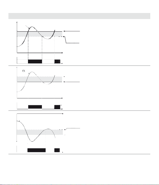
12 Alarm Intervention Modes
Alarm Spv
Pv
O
On On
O
Hysteresis
parameter
> 0
Time
Alarm
output
Absolute Alarm or Threshol d Alarm (a . AL. selection)
Absolute alarm with controller in
heating functioning (par. 11
1
2
On On
O
Pv
O
3
O
On On
O
selected
greater than “0” (par. 28
N.B.*
Hysteresis
parameter
< 0
Absolute alarm with controller in
Alarm Spv
heating functioning (par. 11
selected
less than “0” (par. 28
Time
N.B.*
Alarm
output
Time
Hysteresis
Absolute alarm with controller in
parameter
> 0
cooling functioning (par. 11
selected
Alarm Spv
than “0” (par. 28
N.B.*
Alarm
output
Heat
) and hysteresis value
Heat
) and hysteresis value
A.1.HY.
Co o L
) and hysteresis value
A.1.HY.
A.1.HY.
> 0).
Act. t.
Act. t.
< 0).
Act. t.
> 0).
User manual - CN245 - 53
Page 54
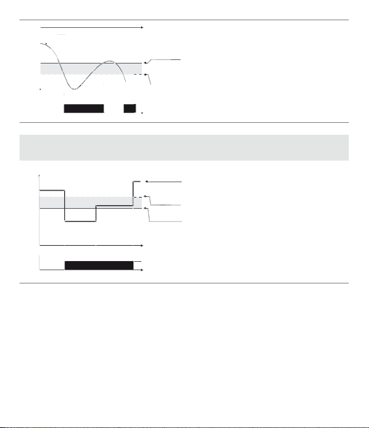
Pv
Time
Absolute alarm with controller in
cooling functioning
Alarm Spv
(par. 11
Act. t.
4
O O
On On
Hysteresis
parameter
hysteresis value less than “0” (par. 28
< 0
A.1.HY.
N.B.*
Alarm
output
selected
< 0).
Absolute Alarm or Threshold Alarm Referring to Setpoint
Command (
1
54 - CN245 - User manual
a . c .AL. selection)
On
O
O
Comand Spv
Hysteresis
parameter
> 0
Alarm Spv
Time
Alarm
output
Absolute alarm refers to the
command set, with the controller in
heating functioning (par. 11
selected
Heat
) and hysteresis value
greater than “0” (par. 28
The command set can be changed
by pressing the arrow keys on front
panel or using serial port RS485
commands.
N.B.*
Co o L
A.1.HY.
) and
Act. t.
> 0).
Page 55
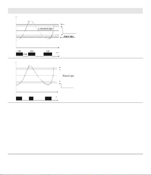
Band Alarm (b . AL. selection)
Alarm Spv
Pv
1
Alarm Spv
Hysteresis
parameter
> 0
Band alarm hysteresis value greater
than “0” (par. 28
A.1.HY.
> 0).
N.B.*
Time
O O
Pv
Comand Spv
2
On On On
O O O
* The exam ple refers to alarm 1; the fu nction can also be ena bled for alarms 2 and 3 o n models
that include it.
Alarm
output
Hysteresis
parameter
< 0
Band alarm hysteresis value less than
Hysteresis
parameter
< 0
Time
Alarm
output
“0” (par. 28
N.B.*
A.1.HY.
< 0).
User manual - CN245 - 55
Page 56
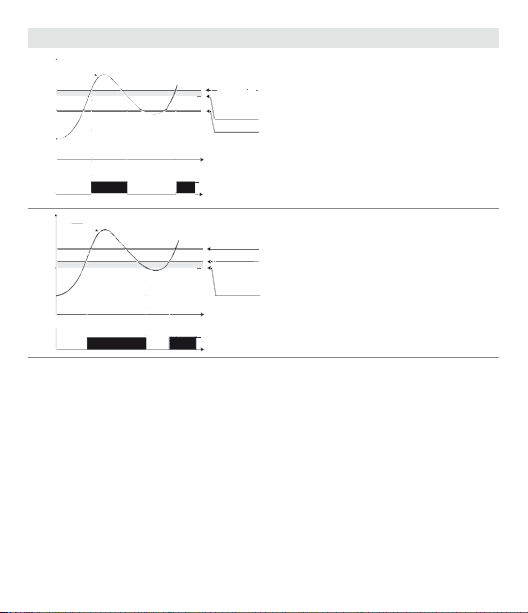
Upper Deviation Alarm (H. d . AL. selection)
Alarm Spv
Comand Spv
Comand Spv
Alarm Spv
Alarm Spv
Alarm Spv
Pv
Alarm Spv
Hysteresis
parameter
> 0
1
O O
On On
Pv
Comand Spv
Comand Spv
Alarm Spv
2
On On
O O
56 - CN245 - User manual
Upper deviation alarm value of
alarm setpoint greater than “0” and
hysteresis value greater than “0” (par.
28
A.1.HY.
Time
Alarm
output
> 0).
N.B.**
Upper deviation alarm value of alarm
setpoint less than “0” and hysteresis
Hysteresis
parameter
value greater than “0” (par. 28
> 0
> 0).
Time
N.B.**
Alarm
output
A.1.HY.
Page 57
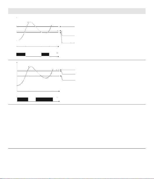
Lower Deviation Alarm (L. d .AL. selection)
Alarm Spv
Comand Spv
Comand Spv
Comand Spv
Comand Spv
Alarm Spv
Alarm Spv
Pv
Comand Spv
Hysteresis
parameter
1
On On
O O
Pv
2
On On
O O
** a) The example re fers to alarm 1; the fu nction can also be enabled fo r alarms 2 and 3 on
models that include it.
b) With hysteresis value less than “ 0” (
setpoint.
> 0
Alarm Spv
Time
Alarm
output
Hysteresis
parameter
> 0
Alarm Spv
Comand Spv
Time
Alarm
output
Lower deviation alarm value of
alarm setpoint greater than “0” and
hysteresis value greater than “0” (par.
28
A.1.HY.
> 0).
N.B.**
Lower deviation alarm value of alarm
setpoint less than “0” and hysteresis
value greater than “0” (par. 28
> 0).
N.B.**
A.1.HY.
< 0) the broken line moves unde r the alarm
User manual - CN245 - 57
A.1.HY.
Page 58

13 Table of Anomaly Signals
If installation malfunctions, controller will switch o regulation output and will
report the anomaly. For example, controller will report failure of a connected
thermocouple visualizing
below.
Cause what to do
E-01
Error in EEPROM cell
programming.
SYS. E
Cold junction sensor fault or
E-02
room temperature outside of
SYS. E
allowed limits.
Incorrect conguration data.
E-04
Possible loss of calibration
SYS. E
values.
E-05
Thermocouple open or temperature outside of limits.
prb .
E-08
Missing calibration data. Call Assistance.
SYS. E
58 - CN245 - User manual
e -05
ashing on display for other signals, see table
Call Assistance.
Call Assistance.
Check if the conguration
parameters are correct.
Check the connection with the
sensors and their integrity.
Page 59

14 Summary of Conguration parameters
Date: Model CN245:
Installer: System:
Notes:
N. Pa r. Description
1
2
3
4
5
6
7
8
9
10
11
12
13
14
15
16
17
18
19
20
21
22
23
Command output type selection
c. oUT
Analogue input conguration
sen.
Number of decimal points
d. p.
Lower limit setpoint
Lo L. s .
Upper limit setpoint
u p .L. s .
Lower limit range AN1 only for linear
Lo . L.i .
Upper limit range AN1 only for linear
u p .L.i .
Automatic setting of linear input limit s
La t c
Oset calibration
o . c AL.
Gain calibration
G. cAL.
Regulation type
act.t.
Command output reset type
c. re.
Contact state for command output in case of error
c. se.
Dene the OUT1 led state
c. Ld.
Hysteresis in ON / OFF or dead band in P.I.D.
c. Hy .
Command delay
c. de .
Command setpoint protection
c. s. p.
Proportional band
p. b.
Integral time
t.i .
Derivative time
t.d.
Cycle t ime
t. c.
Upper limit of heating output percentage
o . p o L.
Alarm 1 selection
AL. 1
User manual - CN245 - 59
Page 60

N. Pa r. Description
24
25
26
27
28
29
30
31
32
33
34
35
36
37
38
47
48
49
50
51
52
53
54
55
56
57
58
59
60 - CN245 - User manual
Alarm 1 output contact and intervention type
A.1. s . o.
Reset type of alarm 1 contact
a1 . re .
State of contac t for alarm 1 output
a .1 . s . e .
State of OUT2 led
a.1.Ld.
Alarm 1 hysteresis
A.1.HY
Alarm 1 delay
a .1 . d e .
Alarm 1 set protection
a .1 . s . p .
Alarm 2 selection
aL. 2
Alarm 2 output contact and intervention type
a.2.s.o.
Reset type of alarm 2 contact
a . 2. r e
State of contac t for alarm 2 output
a . 2.s . e .
State of OUT2 led
a.2.Ld.
Alarm 2 hysteresis
A.2.HY.
Alarm 2 delay
a . 2. d e.
Alarm 2 set protection alarm 2 set prote ction
a . 2.s . p .
Activation and scale range of Current transformer
t.a.
Intervention threshold of Loop Break Alarm
L.b.a.t.
Delay time for Loop Break Alarm intervention
L. b.a.d.
Cooling uid type
co o . f.
Proportional band multiplier
p.b.m.
Overlapping / Dead band
ou.d.b.
Cycle time for cooling output
co.t.c.
Analog converter lter
c. f Lt.
Sampling frequency of analog converter
c.Frn .
Display lter
u . fLt.
Autotuning t ype selection
tun e
Command setpoint deviation for tuning threshold
s.d.tu.
Operating mode
op.mo
Page 61

N. Pa r. Description
60
61
62
63
64
65
66
67
68
69
70
71
72
73
Automatic / manual selection
au.ma.
Digital input functioning
d Gt.i .
Gradient for Soft-Start
Gra d .
Cycle maintenance time
m a . ti .
Gradient change and maintenance time by user
u.m.c.p.
Display data selection
ui . t Y.
Degree type selection
d e G r.
Retransmission for output 0-10 V or 4 .. 20 mA
re tr.
Lower limit range for linear output
Lo L. r.
Upper limit range for linear output
up.L.r.
Select baud rate for serial communic ation
bd . rt.
Select slave address
sL. a d .
Select the serial delay
se. d e.
Lower limit of heating output percentage
L.L. o . p .
Notes / Updates
User manual - CN245 - 61
Page 62

Introduzione
Grazie per aver scelto un regolatore Omega.
Il modello CN245 Omega è un regolatore per l’utilizzo in applicazioni su quadro
di comando con montaggio a barra DIN.
In un singolo strumento sono disponibili le selezioni relative alla connessione dei
sensori e al co mando di attuatori, con in aggiunta un’utile alimentazione a range
esteso da 24 .. 230 Vac/Vdc.
Con le 18 sonde selezionabili e l’uscita congurabile come Relè , Comando SSR,
4 .. 20 mA e 0 .. 10Volt l’utiliz zatore o il rivenditore può gestire al meglio le scor te
di magazzino razionalizzando investimento e disponibilità dei dispositivi. Il
modello è completo di comunicazione seriale RS485 Modbus Rtu e funzione di
controllo del carico tramite trasformatore TA. La ripetibilità in serie delle operazioni di parametrizzazione è ulteriormente semplicata dalle nuove CN-CongModule che essendo dotate di batteria interna non richiedono il cablaggio per
alimentare il regolatore.
1 Norme di sicurezza
Prima di utili zzare il disposi tivo, leggere con att enzione le istruz ioni e le misure di
sicurezza contenute in questo manuale. Disconnettere l’alimentazione prima di
qualsiasi intervento sulle connessioni elettriche o settaggi hardware.
L’utilizzo/manutenzione è riservato a personale qualicato ed è da intendersi
esclusivamente nel rispetto dei dati tecnici e delle condizioni ambientali dichiarate.
Non gettare le apparecchiature elettriche tra i riuti domestici.
Secondo la Direttiva Europea 2002/96/CE, le apparecchiature elettriche esauste
devono essere raccolte separatamente al ne di essere reimpiegate o riciclate in
modo eco-compatibile.
62 - CN245 - Manuale d’uso
Page 63

2 Identicazione del modello
Alimentazione 24 .. 230 Vac/Vdc +/- 15% 50/60Hz – 5,5VA
CN245-R1R2F3C4 2 Relè da 5A + 1 Ssr/V/mA + Rs485 +Ta*
* Modello con ingresso TA per funzione loop break alarm.
3 Dati tecnici
3.1 Caratteristiche generali
Displays 4 display da 0,40 pollici + 4 display da 0,30 pollici
Temperatura
di esercizio
Protezione IP65 su Frontale, IP20 custodia e morsetti
Materiale PC ABS UL94VO autoestinguente
Peso 165 g
0-45°C, umidità 35..95uR%
3.2 Caratteristiche hardware
AN1 Congurabile via software
Ingresso Termocoppie tipo K , S,
R, J. Compensazione automatica
del giunto freddo da 0°C a 50 °C.
Ingresso
analogici
Uscite relè
Termoresistenze: PT100, PT500,
PT1000, Ni100, PTC1K, NTC10K.
Ingresso V/I: 0 -10V, 0-20 o
4-20mA, 0 -40mV, TA da 50mA
1024 p unti
Ingresso Pot:.: 6K, 150K,
2 relè congurabili come uscita
comando e allarme.
Tolleranza (25 °C)
+/-0,2% ±1 digit (su F.s.) per
termocoppia, termoresistenza
e V / mA.
Precisione giunto freddo
0,1°C/°C.
Impedenza:
0-10V: Ri >110 K
0-2 0mA: Ri<5
4-2 0mA: Ri<5
0-40mV: Ri>1M
Contatti da 5A-250V~
Manuale d’uso - CN245 - 63
Page 64

1 normalizzata
0/4 .. 20mA /SSR/0 .. 10Volt.
Uscita SSR
Congurabili come uscita
comando o ritrasmissione
setpoint o setpoint
3.3 Caratteristiche software
Algoritmi
regolazione
Banda
proporzionale
Tempo integrale 0,0...999,9 sec (0 esclude)
Tempo derivativo 0,0...999,9 sec (0 esclude)
Funzioni del
regolatore
64 - CN245 - Manuale d’uso
ON-OFF con isteresi.
P, PI, PID, PD a tempo proporzionale
0...9999°C o °F
Tuning manuale o automatico allarme selezionabile,
protezione set comando e allarme, selezione funzioni da
ingresso digitale, ciclo preprogrammato con Start/Stop.
Congurabile:
0-10 V con 9500 punti +/-0.2%
(s u F.s. )
0-2 0 mA con 7500 punti +/- 0.2%
(s u F.s. )
4-2 0 mA con 600 0 punti +/-0.2%
(s u F.s. )
Page 65
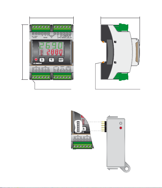
4 Dimensioni e installazione
90 mm
72 mm
CN243
64 mm
Extractable terminal blocks
Morsettiere Estraibili
Din rail mounting guide EN50022
Attacco a guida DIN EN50022
CN-CONFIG-MODULE
(optional)
Manuale d’uso - CN245 - 65
Page 66
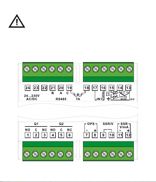
5 Collegamenti elettrici
Benché questo regolatore sia stato progettato per resistere ai più
gravosi disturbi presenti in ambienti industriali è buona norma
- Distinguere la linea di alimentazioni da quelle di p otenza.
- Evitare la vicinanza di gruppi di teleruttori, contattori elet tromagnetici, motori
- Evitare la vicinanza di gruppi di potenza, in par ticolare se a controllo di fase.
seguire la seguenti precauzioni:
di grossa potenza e comunque usare gli app ositi ltri.
5.1 Schema di collegamento
66 - CN245 - Manuale d’uso
Page 67
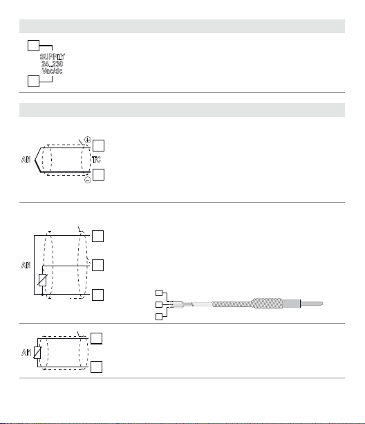
Alimentazione
24
15
23
SUPPLY
24..230
Vac/dc
Alimentazione switching a range esteso
24 .. 230 Vac/dc ±15% 50/60Hz – 5,5VA
Ingresso analogico AN1
Shield/Schermo
AI1
AI1
AI1
Shield/Schermo
PT/NI100
Shield/Schermo
PTC/NTC
Rosso
Red
Bianco
White
Rosso
Red
TC
14
15
14
Per termocoppie K, S, R, J.
• Rispettarelapolarità
13
• Pereventualiprolungheutilizzarecavocompensato
e morset ti adatti alla termocoppia utiliz zata
(comp esati)
14
• Quandosiusailcavoschermato,laschermaturava
collegata a terra ad una sola estremità
Per termoresistenze P T100, NI100
• Perilcollegamentoatreliusarecavidellastessa
sezione
13
• Perilcollegamentoaduelicortocircuitareimorsetti
13 e 15
• Quandosiusailcavoschermato,laschermaturava
collegata a terra ad una sola estremità
13
RED/ROSSO
WHITE/BIANCO
14
15
RED/ROSSO
Per termoresistenze N TC, PTC , PT500, PT1000 e
potenziometri lineari
Quando si usa il cavo schermato, la schermatura va
collegata a terra ad una sola estremità
Manuale d’uso - CN245 - 67
Page 68
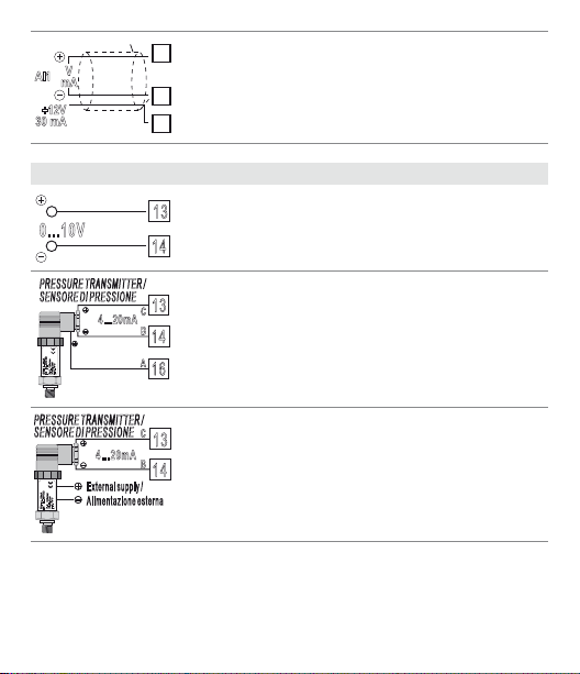
AI1
PRESSURE TRANSMITTER /
PRESSURE TRANSMITTER /
+12V
30 mA
mA
V
Shield/Schermo
13
Per segnali normalizzati in corrente e tensione
• Rispettarelapolarità
• Quandosiusailcavoschermato,laschermaturava
14
collegata a terra ad una sola estremità
16
Esempi di collegamento per ingressi normalizzati
13
0...10V
Per segnali normalizzati in tensione 0 .. .10V
Rispettare le polarità
14
SENSORE DI PRESSIONE
4...20mA
P :0...100mbar
Pmax :3bar
T :0..70°C
OUT : 4...20mA
IN :9...33V DC
SENSORE DI PRESSIONE
4...20mA
External supply /
Alimentazione esterna
P :0...100mbar
Pmax :3bar
T :0..70°C
OUT : 4...20mA
IN :9...33V DC
68 - CN245 - Manuale d’uso
Per segnali normalizzati in corrente 0/4 .. .20mA con
13
C
sensore a tre li
B
Rispettare le polarità
14
A=Uscita sensore
A
B=Massa sensore
16
C=Alimentazione sensore (12Vdc / 30mA)
C
Per segnali normalizzati in corrente 0/4..20mA
13
con sensore ad alimentazione esterna
B
14
Rispettare le polarità
A=Uscita sensore
B=Massa sensore
Page 69
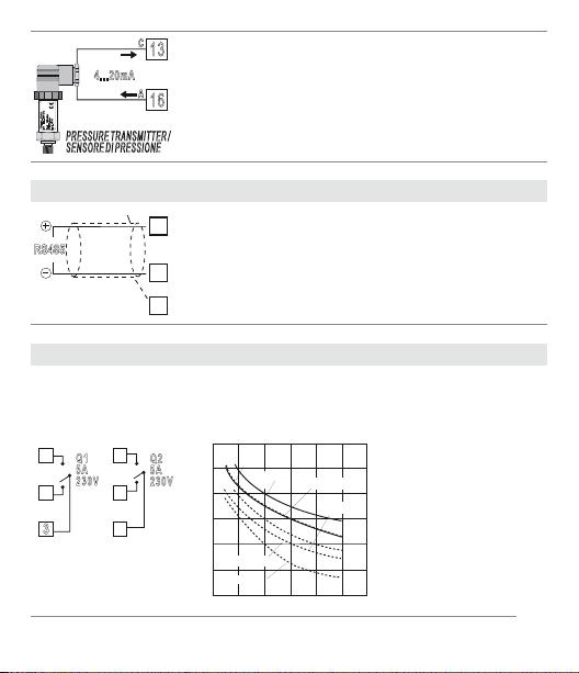
SENSORE DI PRESSIONE
4...20mA
4
OUT : 4...20mA
IN :9...33V DC
P :0...100mbar
Pmax :3bar
T :0..70°C
PRESSURE TRANSMITTER /
Ingresso Seriale
Shield/Schermo
RS485
Uscita relè Q1 Q2
1
Q1
5A
230V
2
3
C
13
Per segnali normalizzati in corrente 0/4 .. .20mA con
sensore a due li
A
Rispettare le polarità
16
A=Uscita sensore
C=Alimentazione sensore (12Vdc / 30mA)
Comunicazione RS485 Modbus RTU
21
• Perreticonpiùdicinquestrumentialimentarein
bassa tensione
• Quandosiusailcavoschermato,laschermaturava
20
collegata a terra ad una sola estremità (connessa al
19
morsetto 19)
Portata contatti:
• 5A,250Vac,caricoresistivo,10
• 20/2A,250Vac,cosφ= 0.3,10
4
Q2
5A
230V
5
operations)
6
Service life (x10
200
100
50
20
10
AC250V COS ø=0.4
5
0
DC30 V t=15ms
Life Curve
AC250V
DC30 V
AC125 V
2 3 4
1
Contact load current (A)
AC125V COS ø=0.4
DC30 V t=7ms
5
5
operazioni.
5
operazioni.
Manuale d’uso - CN245 - 69
Page 70
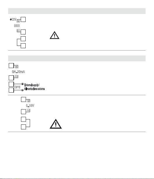
Uscita SSR
9
12
12
+12V
12
SSR
11
10
Uscita mA o Volt
0/4..20mA
11
8
External supply /
OPS
Alimentazione esterna
7
Uscita comando SSR portata 12V/30mA
Ponticellare il morse tto 9 con il 10 come in
gura per utilizzare l’uscita SSR
Morsetti 11-12: uscita continua in mA congurabile da
parametri come comando (par.
del processo-setp oint (par.
Morsetti 7-8: alimentazione esterna opzionale del loop
di corrente (max 24Vdc).
re tr.
c.out
) o ritrasmissione
).
0..10V
11
10
9
70 - CN245 - Manuale d’uso
Uscita continua in Volt congurabile da parametri come
comando (par.
setpoint (par.
c.out
) o ritrasmissione del processo-
re tr.
Ponticellare il morse tto 9 con il 10 come in
gura per utilizzare l’uscita continua in Volt.
).
Page 71
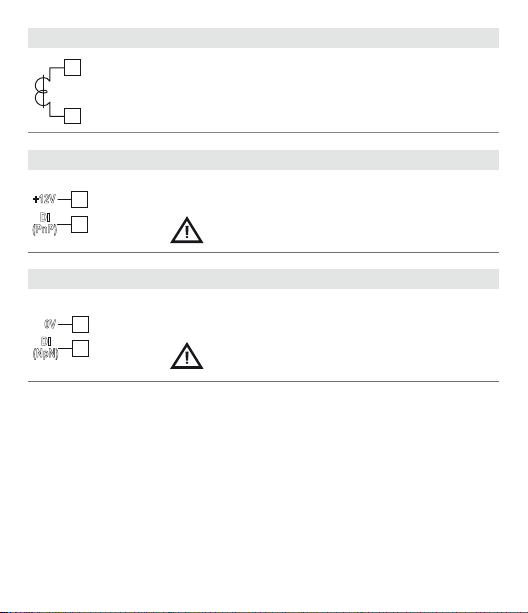
Ingresso TA
18
TA
19
Ingresso digitale (1)
+12V
16
DI
17
(PnP)
Ingresso digitale (2)
0V
14
DI
15
(NpN)
• Ingressopertrasformatoreamperometricoda50mA
• Tempodicampionamento80ms
• Congurabiledaparametri
Per utiliz zo senza connessione TA
Ingresso digitale da parametro
d Gt.i .
Ponticellare il morse tto 16 con il 17 per
attivare l'ingresso digitale.
Per utilizzo insieme all’ingresso TA
Ingresso digitale da parametro
d Gt.i .
L’utilizzo dell’ingresso digitale in questa modalità è possibile solo co n sensori tipo Tc, 0 .. 10V,
0/4 .. 20mA e 0 .. 40 mV.
Manuale d’uso - CN245 - 71
Page 72
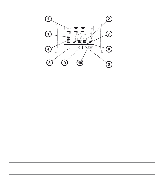
6 Funzione dei visualizzatori e tasti
6.1 Indicatori numerici (display)
Normalmente visualiz za il processo, ma può visualizzare
1
2
1234
1234
anche i setp oint. In fase di congurazione visualizza il
parametro che si sta inserendo.
Normalmente visualiz za i setpoint. In fase di congurazione visualiz za il valore del parametro che si sta inserendo.
6.2 Signicato delle spie di stato (led)
C1
3
C2
4 A1 A2 A3 Si accendono quando l’allarme corrispondente è attivo.
5 MAN Si accende con la funzione “Manuale” attiva.
6 TUN
7 REM
72 - CN245 - Manuale d’uso
Si accendono quando l’uscita comando è attiva. C1 con
comando a relè/SSR/mA/ Volt o C1 (apri) e C2 (chiudi) nel
caso di comando valvola motorizzata.
Si accende quando il regolatore stà eseguendo un ciclo di
“Autotune”.
Si accende quando il regolatore sta comunicando attraverso la porta seriale.
Page 73
6.3 Tas ti
• Consentediincrementareilsetpointprincipale
• Infasedicongurazioneconsentediscorrereiparametri.
8
Insieme al tasto
• Premutodopoiltasto
SET
li modica.
SET
consente di incrementare i setpoint
di allarme.
• Consentedidecrementareilsetpointprincipale
9
Insieme al tasto
• Premutodopoiltasto
• Infasedicongurazioneconsentediscorrereiparametri.
SET
li modica.
SET
consente di decrementare i setpoint
di allarme.
• Permettedivisualizzareilsetpointdiallarmeedientrarenella
SET
10
funzione di lancio dell’autotuning.
• Permettedivariareiparametridicongurazione.
7 Funzioni del regolatore
7.1 Modica valore setpoint principale e setpoint di
allarme
Il valore dei setpoint può essere modicato da tastiera come segue:
Premere Eetto Eseguire
1
o
SET
2
3
o
La cifra sul display 2 varia di
conseguenza
Visualizza setpoint di allarme su display 1
La cifra sul display 2 varia di
conseguenza
Incrementare o diminuire il valore del setpoint
principale
Incrementare o diminuire il valore del setpoint
principale
Manuale d’uso - CN245 - 73
Page 74

7. 2 Auto-tune
La procedura Auto-tune per il calcolo dei parametri di regolazione può essere
manuale o automatica e viene selezionata da par. 57
Tu n e .
7. 3 Lancio dell’AutoTuning “Manuale”
La procedura manuale permette all’utente maggiore essibilità nel decidere
quando aggiornare i parametri di lavoro dell’argoritmo PID. La procedura può
essere attivata in due mo di.
• Lancio del Tune da tastiera:
Premere il tasto
display 2 su
e la procedura ha inizio.
• Lancio del Tune da ingresso digitale:
Selezionare
digitale (commutazione su fronte) il led TUN si accende, alla seconda si
spegne.
SET
nché il display 1 non visualiz za la scritta
off
, premere , il display 2 visualizza on. Il led TUN si accende
tun e
su parametro 61
d Gt.i .
Alla prima attuazione dell’ingresso
tun e
con il
7.4 Tuning “Automatico”
Il tuning automatico si attiva all’accensione dello strumento o quando viene
modicato il setpoint di un valore superiore al 35%.
Per evitare overshoot, il punto dove il regolatore calcola i nuovi parametri PID è
determinato dal valore di set meno il valore “Set Deviation Tune” (Parametro 58
S.d.tu.
) Per uscire dal t uning lasciando invar iati i valori PID, è sucie nte premere
SET
il tasto
on
termina.
74 - CN245 - Manuale d’uso
nché il display 1 non visualiz za la scritta
, premere , il display 2 visualizza
tun e
off
. Il led TUN si spegne e la procedura
con il display 2 su
Page 75

7. 5 Soft Start
All’accensione il regolatore per raggiungere il setpoint segue un gradiente di
salita imp ostato in Unità (es. Grado / Ora).
Impostare sul parametro 62
Ora; alla successiva accensione lo strumento eseguirà la funzione Soft-Start.
Se il parametro 59
diverso da 0, dopo l’accensione, trascorso il tempo impostato sul parametro 63,
il setpoint non segue più il gradiente, ma si porta alla massima potenza verso
il setpoint nale. L’autotuning non funziona quando il Soft-Start è attivo: se il
parametro 63
l’autotuning parte allo scadere del tempo di Soft-Start, mentre se il parametro
57
tun e
scadere del Soft-Start.
m a . ti .
è impostato su
GrAd .
il valore di incremento desiderato in Unità/
op.mo.
è impostato su
è diverso da 0 e i l parametro 57
Man.
la funzione può essere lanciata solamente allo
co nt.
e il parametro 63
tun e
è imposta to su
m a . ti .
Auto
è
7.6 Regolazione automatico / manuale per controllo %
uscita
Questa funzione permette di passare dal funzionamento automatico al comando
manuale della percentuale dell’uscita.
Con il parametro 60
1 La prima selezione (
sul display 1, mentre sul display due appare
Premere il tasto per visualizzare
zazione del processo, variare con i tasti
Per tornare in automatico, con la stessa procedura, selezionare
display 2: subito si spegne il led MAN e il funzionamento torna in automatico.
2 La seconda selezione (
importanti varianti:
• Nelcasoditemporaneamancanzaditensioneocomunquedopounospe-
gnimento, accendendo il regolatore, verrà mantenuto sia il funzionamento in
manuale, sia il valore di percentuale dell’uscita precedentemente impostato.
• Nelcasodirotturadelsensoreduranteilfunzionamentoautomatico,ilre -
Au.ma.
è possibile selezionare due modalità.
en.
) permet te di abilitare con il tasto
au to.
man,
; è ora possibile, durante la visualiz-
e la percentuale dell’uscita.
en .st.
) abilita lo stesso funzionamento, ma con due
SET
la scritta
p.---
au to
sul
Manuale d’uso - CN245 - 75
,
Page 76
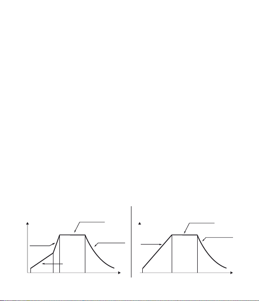
golatore si porterà in manuale mantenendo invariata la percentuale di uscita
comando generata dal P.I.D. subito prima della rot tura.
Es: su un estrusore viene mantenuto il comando in percentuale della resisten-
za (carico) anche nel caso di guas to sulla sonda in ingresso.
7.7 Ciclo pre-programmato
Questa funzione si abilita impostando
Prima selezione (
Pr. c y
):
il regolatore raggiunge il setpoint 1 seguendo il gradiente impostato nel parametro 62
Gra d .
, poi sale al la massima potenza ver so il setpoint 2. Quan do il
processo lo raggiunge, lo mantiene per il tempo impostato nel parametro 63
m a . ti .
Allo scadere, l’uscita di comando è disabilitata e lo strumento visua-
lizza
stop
. La partenza del ciclo avviene al ogni accensione dello strumento,
oppure da ingresso digitale se abilitato per questo funzionamento (vedi
parametro 61
Seconda selezione (
d Gt.i .
).
p.c.s.s.
la partenza è decisa solo dall’attivazione dell’ingresso digitale, a prescindere
dall’impostazione del parametro 61
giunge il setpoint 1 seguendo il gradiente impostato nel parame tro 62
Quando il processo lo raggiunge, lo mantiene per il tempo impostato nel
parametro 63
Allo scad ere, l’uscita di comando è d isabilitata e lo str umento visualizz a
First selection
Primo caso
Setpoint
Max. Power
Potenza
massima
76 - CN245 - Manuale d’uso
Setpoint 2
Gradient
Gradiente
m a . t.i .
Setpoint 1
Hold
Mantenimento
):
Natural cooling
Rareddamento
naturale
p r. cy .
oppure
p.c.s.s.
d Gt.i .
Alla partenza, il regolatore rag-
Second selection
Secondo caso
Setpoint 1
Setpoint
Gradient
Gradiente
nel par. 59
Hold
Mantenimento
Natural cooling
Rareddamento
naturale
op.mo.
Gra d .
stop
TempoTime
.
Page 77

Variante (
S.S. cY.
Selezionando
selezione (
inferiore al SET1, lo strumento regola la potenza dell’uscita al valore percentuale
impostato sul parametro 62
Quando il pr ocesso supera il SET1 o è t rascorso il tempo imp ostato sul paramet ro
63
M A . ti .
tiene per un tempo innito.
Se sul parametro 59
parametro 17
label del SET2 diventa semplicemente SET. In questa modalità, lanciando il tune
manuale durante la regolazione sul SET1 non si attiva il led TUN nchè non si
passa alla re golazione sul SET2.
L’autotuning (automatico e manuale) funziona solo se sta regolando sul SET2. Se
viene lanciato durante la regolazione sul SET1, rimane in standby per poi partire
appena si passa alla regolazione sul SE T2.
):
S.S. cY.
(Soft Star t Cycle) il rego latore si comport a come nella prima
Pr. c y
) con due importanti varianti. Se all’accensione il processo è
GrAd .
, il regolatore porta il processo al SET2 alla massima potenza e lo man-
oP.Mo.
c. S. P.
è impostato
: in questo mo do non viene più visua lizzato il SET1, mentre l a
S.S. cY.
è possibile selezionare
Hi d E
sul
7.8 CN-Cong-Module
È possibile duplicare parametri e setpoint da un regolatore ad un altro mediante
l’uso del CN-Cong-Module.
Sono previste due modalità:
• Con regolatore connesso all’alimentazione
Inserire il CN- Cong-Module con regolatore spento.
All’accensione il display 1 visualizza
se nel modulo sono salvati valori corretti). Premere il tasto
visualizza
Lo a d
valori e riparte.
, quindi conf ermare con il tasto
mem o
e il display 2 visualizza
SET
. Il regolat ore carica i nuovi
----
(solo
, il display 2
Manuale d’uso - CN245 - 77
Page 78
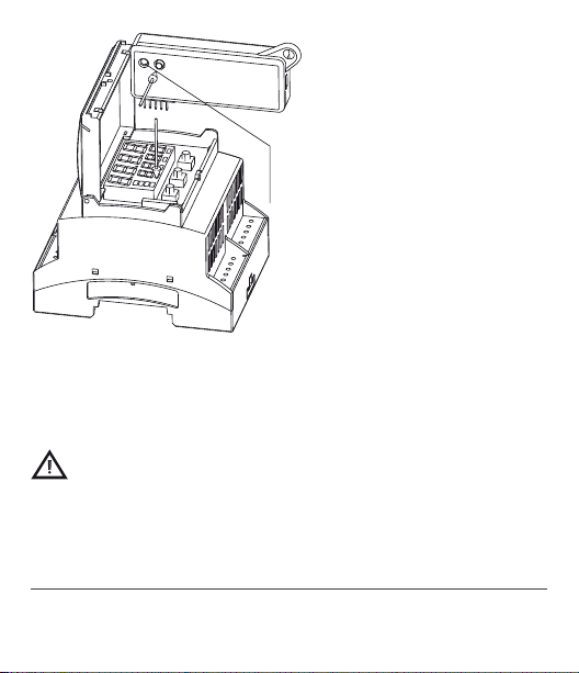
RED LIGHT: waiting for programming
GREEN LIGHT: done
LED ROSSO: accceso in programmazione
LED VERDE: programmazione eseguita
• Con regolatore non connesso all’alimentazione
Il CN-Cong-Module è dotato di batteria interna con autonomia per circa 1000
utilizzi. Inserire il CN -Cong-Module e premere i b ottone per la programmazione.
Durante la sc rittura dei pa rametri il led si acce nde rosso, al termin e della procedura si accende ve rde. È possibile ripetere la procedura senza particolari attenzioni.
Aggiornamento CN-Cong-Module.
Per aggiornare i valori del modulo, seguire il procedimento descritto nella prima
modalità, impostando
regolatore
11
. Entrare in congurazione e variare almeno un parametro.
----
sul display 2 in modo da non cari care i parametri sul
Uscendo dalla congurazione il salvataggio sarà automatico.
11
Nel caso in cui all’accensione il regolatore non visualizzi
sono dati sal vati nel CN-Con g-Module, m a è comunque possib ile aggiornarn e i valori.
78 - CN245 - Manuale d’uso
mem o
signica che non ci
Page 79
8 Funzione LATCH ON
Per l’impiego con ingresso
normalizzati (0 .. 10V, 0...40mV, 0/4 .. 20mA), è possibile associare il valore di
inizio scala (parametro 6
di ne scala (parametro 7
metro 8
La t c.
lo strumento visualizzerà 0 (mantenendo comunque il campo scala compreso
tra
Lo . L.i .
u.0in.
Se si imposta
dello strumento; se si imposta
tarato. Per utilizzare la funzione LATCH ON congurare come desiderato il parametro
congurato come
e
u p .L.i .
nel parametro 8
u.0in.
12
La t c.
Per la procedura di taratura fare riferimento alla seguente tabella:
Premere Eetto Eseguire
+
1
assieme
2
3
12
La procedura di taratura parte uscendo dalla congurazione dopo aver variato il
parametro.
p o t .1
(pot. 6K) e
Lo . L.i .
) alla posizione di minimo del sensore e quello
u p .L.i .
) alla posizione di massimo del sensore (para-
std .
) tramite l’opzione “zero virtuale” impostando
La t c.
lo zero virtuale andrà reimpostato dopo ogni accensione
u.0 st.
Esce dalla congurazione parametri. Il display 2 visualizza
la scritta
La t c.
Fissa il valore sul minimo.
Il display visualizza L
Fissa il valore sul massimo.
Il display visualizza
po t.2
(pot.150K) e con ingressi
). È inoltre possibile ssare il punto in cui
u.0 st.
oppure
lo zero virtuale resterà sso una volta
Posizionare il sensore sul
valore minimo di funzionamento
ow
Hi G h
(associato a
Posizionare il sensore
sul valore massimo di
funzionamento
(associato a
Per uscire dalla procedura
standard tenere premuto
SET
zione con “zero virtuale
”posizionare il sensore
nel punto di zero.
Lo . L.i .
)
u p .L.i .
)
. Nel caso di imposta-
Manuale d’uso - CN245 - 79
Page 80
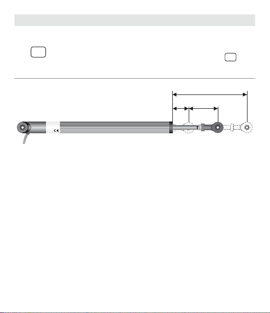
Premere E etto Eseguire
Max
Fissa il valore di zero virtuale.
Il display visualizza
SET
4
NB: nel caso di selezione
u.0in.
la procedura al punto
4 va eseguita ad ogni riaccensione.
ui r t.
Per uscire dalla procedura
tenere premuto
SET
.
Min Zero
8.1 LoopBreakAlarmsuTA(Trasformatore
Amperometrico)
Permette di misurare la corrente sul carico per gestire un allarme in caso di
malfunzionamento (con stadio di potenza in corto oppure sempre aperto). Il
trasfor matore amperometr ico collegato ai morsetti 15 e 16 deve essere da 50 mA
(tempo di campionamento 80 ms).
• Impostaresulparametro47
matore amperometrico.
• Impostare sul parametro 48
Loop Break Alarm.
• Impostaresulparametro 49
Loop Break Alarm.
• È possibile associare l’allarme ad un relè, impostando il parametro
oppure
AL. 3
Nel caso un te leruttore o rel è allo stato solido d ovesse restare sem pre chiuso il re-
80 - CN245 - Manuale d’uso
come
L. b.a.
t.a.
il valore di fondo scala in Ampere del trasfor-
L.b.a.t.
la soglia di intervento in Ampere del
L. b.a.d.
il tempo di ritardo per l’intervento del
AL. 1, AL. 2
Page 81

golatore segnala il guasto visualizzando
con il setpoint di comando).
Nel caso invece lo stadio di potenza dovesse restare sempre aperto, oppure la
corrente sul carico fosse inferiore al valore impostato su
visualizza sul display 2
fase di chiusura dello stadio di potenz a.
L. b.a.o.
L.b.a.c.
sul display 2 (alternativamente
L.b.a.t.
È possibile visualizzare la corrente assorbita in
, il regolatore
Premere Eetto Eseguire
SET
Premere
Questo tasto, in modo cicli-
SET
1
Impostando sul parametro 48
corrente assorbita senza mai generare il Loop Break Alarm.
co, permette di visualizzare
sul display 2 percentuale di
uscita, selezione auto/man,
setpoint ed allarmi.
L.b.a.t.
il valore 0 è possibile visualizzare la
visualizzazione sul
display 1 della scritta
am.t.a.
della corrente in Ampere
(
t.a.
Il valore è mantenuto anche quando non circola
corrente sul carico.
no alla
, e sul display 2
>0).
Manuale d’uso - CN245 - 81
Page 82

8.2 Funzioni da Ingresso digitale
Il CN245 integra alcune funzionalità relative all’ingresso digitale, e può essere
abilitato utilizzando i parametri 59
•Parametro 59
NB: Utilizzando le seguenti impostazioni, il parametro 61
ignorato.
2t.s .
2t. s .i .
3 t. s .i .
4 t. s .i .
t. res .
p.c.s.s.
I vari setpoint possono essere impostati durante il funzionamento premendo il tasto
•Parametro61
NB: Le impostazioni su questo parametro sono considerate solo impostando
st.st.
rn.n.o.
rn.n.c.
L.c.n.o.
Lc.n . c.
tun e
a.ma.i.
a.ma.c.
82 - CN245 - Manuale d’uso
op.mo.
Cambio setpoint a due soglie: con contatto aperto il CN245 regola
su SET1; con contatto chiuso regola su SET2;
Cambio setpoint a due soglie: la selezione del punto di lavoro
viene fatta agendo con un impulso sull’ingresso digitale;
Cambio setpoint a tre soglie con impulso sull’ingresso digitale;
Cambio setpoint a quattro soglie con impulso sull’ingresso digitale;
: Funzione personalizzata;
Ciclo pre-programmato (Par. 7.7 pag. 76)
SET
.
d Gt.i .
co nt.
oppure
Start / Stop; agendo sull’ingresso digitale il regolatore passa
Run N.O. Il regolatore è in start solamente con ingresso chiuso;
Run N.C. Il regolatore è in start solamente con ingresso aperto;
Con ingresso aperto blocca la lettura delle sonde;
Abilita/disabilita il Tuning se il par. 57
Se par. 60
Se par. 60
p r. cY.
alternativamente da start a stop;
Con ingresso chiuso blocca la lettura delle sonde;
au.ma.
so il regolatore passa alternativame nte da regolazione au tomatica
a regolazione manuale;
au.ma.
automatico con ingresso aperto e in manuale con ingresso chiuso.
op.mo.
e 61
sul parametro 59
è impostato su
è impostato su
d Gt.i .
op.mo.
tun e
en.
o
en.
è impostato su
en .st.
agendo sull’ingres-
o
en .st.
d Gt.i .
viene
man.
il CN245 regola in
;
Page 83

NB: per la connessione elet trica dell’ingresso digitale vedi (Par. 5.1 pag. 66).
Le funzioni da ingresso digitale non sono disponibili con sonde PT100 e NI100 nel
caso sia utilizzato anche l’ingresso per trasformatore TA.
8.3 Funzionamento in doppia azione (caldo-freddo)
Il CN245 è adatto a funzionare anche su impianti che prevedono un’azione
combinata caldo-freddo.
L’uscita di comando deve essere congurata in PID caldo (
maggiore di 0), e uno degli allarmi (
gurato come
dell’azione caldo, l’allarme comanderà invece l’azione refrigerante.
I parametri da congurare per il PID caldo sono:
act.t.
p. b.
t.i .
t.d.
t. c.
I parametri da congurare per il PID freddo sono (azione associata, per esempio,
all’allarme1):
a L.1
p.b.m.
ou.d.b.
co.t.c.
Il parametro
dell’azione refrigerante secondo la formula:
Banda proporzionale azione refrigerante =
Si avrà così una banda proporzionale per l’azione refrigerante che sarà uguale
a quella dell’azione caldo se
Tempo integrale e Tempo derivativo sono gli stessi per entrambe le azioni.
coo L
. L’uscita di comando va collegata all’attuatore responsabile
=
He a t
: Banda proporzionale azione caldo
: Tempo integrale azione caldo ed azione freddo
: Tempo derivativo azione caldo ed azione freddo
: Tempo di ciclo azione caldo
=
: Moltiplicatore di banda proporzionale
Tipo azione uscita di comando (Caldo)
coo L
Selezione Allarme1 (Cooling)
: Sovrapposizione / Banda morta
: Tempo di ciclo azione freddo
p.b.m.
(che varia da 1.00 a 5.00) determina la banda proporzionale
a L.1, a L.2
oppure
p. b.
p.b.m.
= 1.00, o 5 volte più grande se
act.t.
a L.3
*
p.b.m.
Manuale d’uso - CN245 - 83
=
Heat
e
) deve essere con-
p.b.m.
p. b.
= 5.00.
Page 84
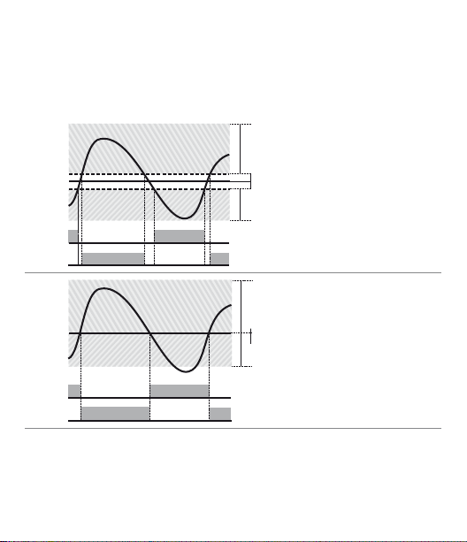
Il parametro
ACTIVE
ACTIVE
SPV
PV
x = COOL
< 0
(HEAT)
COMMAND OUTPUT (HEAT)
ALARM OUTPUT (COOL)
ACTIVE
ACTIVE
SPV
PV
x = COOL
x = COOL
< 0
= 0
(HEAT)
(HEAT)
COMMAND OUTPUT (HEAT)
ALARM OUTPUT (COOL)
COMMAND OUTPUT (HEAT)
ALARM OUTPUT (COOL)
SPV
PV
ACTIVE
ACTIVE
ou.d.b.
determina la sovrapposizione in percentuale tra le due
azioni. Per gli impianti in cui l’uscita scaldante e l’uscita refrigerante non devono
mai essere attive contemporaneamente si congurerà una Banda morta
(
ou.d.b.
≤ 0), viceversa si potrà congurare una sovrapposizione (
ou.d.b.
> 0).
La gura seguente riporta un esempio di PID doppia azione (caldo-freddo) con
t.i .
= 0 e
t.d.
= 0.
1
2
84 - CN245 - Manuale d’uso
Page 85
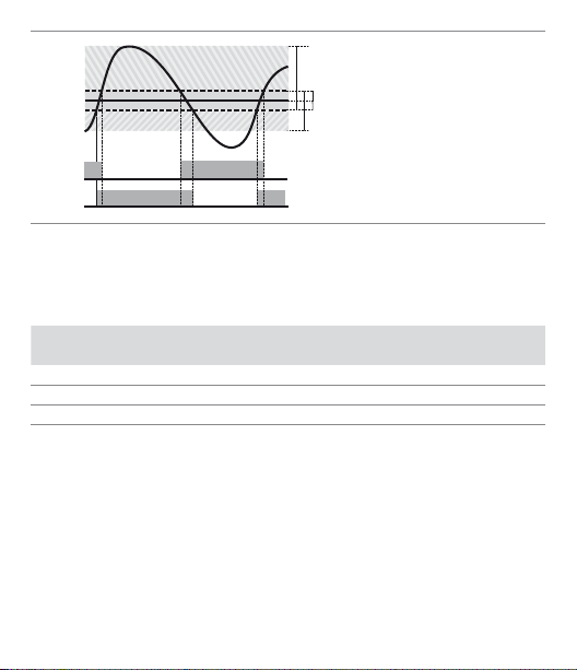
ACTIVE
ACTIVE
SPV
PV
x = COOL
x = COOL
x = COOL
< 0
= 0
> 0
(HEAT)
(HEAT)
(HEAT)
COMMAND OUTPUT (HEAT)
ALARM OUTPUT (COOL)
COMMAND OUTPUT (HEAT)
ALARM OUTPUT (COOL)
COMMAND OUTPUT (HEAT)
ALARM OUTPUT (COOL)
SPV
PV
ACTIVE
ACTIVE
SPV
PV
ACTIVE
ACTIVE
3
Il parametro
t. c.
proporzionale
co.t.c.
Il parametro
p.b.m.
ha lo stesso signicato del tempo di ciclo per l’azione caldo
co o . f.
(Cooling Fluid) pre-seleziona il moltiplicatore di banda
ed il tempo di ciclo
di uido refrigerante:
Tipo di uido
refrigerante
c o o . F.
Ai r
oi L
H2o
Una volta selezionato il parametro
possono essere comunque modicati.
co.t.c.
del PID freddo in base al tipo
P. b . M . co.t.c
Aria 1.0 0 10
Olio 1.2 5 4
Acqua 2.50 2
co o . f.
, i parametri
p.b.m., ou.d.b
Manuale d’uso - CN245 - 85
. e
co.t.c.
Page 86

9 Comunicazione Seriale
Il CN245-R1R2F3C4 è dotato di seriale RS485 è in grado di ricevere e trasmettere
dati tramite protocollo MODBUS RTU. Il dispositivo può essere congurato solo
come Slave. Questa funzione permette il controllo di più regolatori collegati ad
un sistema di supervisione.
Ciascuno strumento risponderà ad un’interrogazione del Master solo se questa
contiene l’indirizzo uguale a quello contenuto nel parametro
permess i vanno da 1 a 254 e non devono es serci regolatori con l o stesso indirizz o
sulla stessa linea.
L’indirizzo 255 può essere usato dal Master per comunicare con tutte le apparecchiature collegate (modalità broadcast), mentre con 0 tutti i dispositivi ricevono
il comando, ma non è prevista alcuna rispos ta.
Il CN245 può introdu rre un ritardo (in millis econdi) della rispo sta alla richiesta d el
Master. Tale ritardo deve essere impostato sul parametro 72
Ad ogni vari azione dei param etri lo strumento s alva il valore in memo ria EEPROM
(100000 cicli di scrittura), mentre il salvataggio dei setpoint avviene con un
ritardo di 10 secondi dall’ultima modica.
NB: Modiche a pportate a Word dive rse da quelle ripor tate nella tabell a seguente possono causare mal funzionamenti dello strumento.
Caratteristiche protocollo Modbus RTU
Selezionabile da parametro 70
4.8 k
Baud-rate
Formato 8, N, 1 (8 bit, no parità, 1 stop)
Funzioni
supportate
86 - CN245 - Manuale d’uso
4.800 bit/Sec.
9.6 k
9.600 bit /Sec.
19.2k
19.200 bit/Sec.
WORD READING (max 20 word) (0x03, 0x04)
SINGLE WORD WRITING (0x06)
MULTIPLE WORDS WRITING (max 20 word) (0x10)
bd . rt.
28.8 k
38 .4 k
57.6 k
sL. a d .
se. d e.
:
28.800 bit/Sec.
38.400 bit/Sec.
57.600 bit/Sec.
Gli indirizzi
Page 87

Si riporta di seguito l ’elenco di tutti gli indirizzi disponibili, dove:
RO Read Only R/W Read / Write WO Write Only
Modbus
Address
0 Tipo dispositivo RO EEPROM
1 Versione software RO EEPROM
5 Address slave RO EEPROM
6 Versione boot RO EEPROM
50 Indirizzamento automatico WO 51 Confronto codice impianto WO -
500 Caricamento valori di default (scrivere 9999) R/W 0
510 Tempo salvataggio setpoint in eeprom (0- 60s) R/W 10
999 Processo sottoposto al ltro in visualizzazione RO -
Processo (gradi con decimo p er sensori di tempe-
1000
ratura; digit per sensori normalizzati)
1001 Setpoint1 R/W EEPROM
1002 Setpoint2 R/W EEPROM
1003 Setpoint3 R/W EEPROM
100 4 Setpoint4 R/W EEPROM
1005 Allarme1 R/W EEPROM
1006 Allarme2 R/W EEPROM
1007 Allarme3 R/W EEPROM
1008 Setpoint gradiente RO EEPROM
Stato relè (0=o, 1=on)
Bit 0 = relè Q1
Bit 1 = relè Q2
1009
Bit 2 = riser vato.
Bit 3 = SSR
1010 Percentuale uscita caldo (0-10000) RO 0
1011 Percentuale uscita f reddo (0-10000) RO 0
Description
Read
Reset
Only
value
RO -
RO 0
Manuale d’uso - CN245 - 87
Page 88

Modbus
Address
Stato allarmi (0=assente, 1=presente)
1012
Bit0 = Allarme 1
Bit1 = Allarme 2
Riarmo manuale: scrivere 0 per riarmare tutti gli
allarmi.
In lettura (0=non riarmabile, 1=riarmabile):
1013
Bit0 = Allarme 1
Bit1 = Allarme 2
Flags errori
Bit0 = Errore scrittura eeprom
Bit1 = Errore let tura eeprom
Bit2 = Errore giunto freddo
Bit3 = Errore processo (sonda)
1014
Bit4 = Errore generico
Bit5 = Errore hardware
Bit6 = Errore L.B.A.O.
Bit7 = Errore L .B.A.C.
Bit8 = Errore tarature mancanti
1015 Temperatura giunto freddo (gradi con decimo) RO -
Start /Stop
1016
0=regolatore in STOP
1=regolatore in START
Lock conversion ON/OFF
1017
0=Lock conversion o
1=Lock conversion on
Tuning ON/OFF
1018
0=Tuning o
1=Tuning on
Selezione automatico/manuale
1019
0=automatico ; 1=manuale
88 - CN245 - Manuale d’uso
Description
Read
Only
RO 0
WO 0
RO 0
R/W 0
R/W 0
R/W 0
R/W 0
Reset
value
Page 89

Modbus
Address
1020 Corrente TA ON (ampere con decimo) RO -
1021 Corrente TA OFF (ampere con decimo) RO
1022 Tempo OFF LINE*(millisecondi) R/W
1023 Corrente istantanea (Ampere) R/W 0
1024 Stato ingresso digitale R/W 0
Tuning sincronizzato per multizona
0 = Tuning OFF (Funzionamento normale del
regolatore)
1 = Uscita comando OFF
1025
2 = Uscita comando ON
3 = Start Tuning
4 = Fine Tuning e comando OFF (Portare la word
1025 al valore 0)
Processo sottoposto al ltro in visualizzazione e
1099
alla selezione del punto decimale
110 0 Processo con selezione del punto decimale RO
1101 Setpoint 1 con selezione del punto decimale R/W EEPROM
110 2 Setpoint 2 con selezione del punto decimale R/W EEPROM
110 3 Setpoint 3 con selezione del punto decimale R/W EEPROM
110 4 Setpoint 4 con selezione del punto decimale R/W EEPROM
110 5 Allarme 1 con selezione del punto decimale R/W EEPROM
110 6 Allarme 2 con selezione del punto de cimale R/W EEPROM
110 7 Allarme 3 con selezione del punto decimale RO EEPROM
110 8 Setpoint gradiente con sel. del punto decimale R/W 0
110 9 Percentuale uscita caldo (0-1000) RO 0
1110 Percentuale uscita caldo (0-100) RO 0
1111 Percentuale uscita freddo (0-1000) RO 0
1112 Percentuale uscita freddo (0-100) R/W EEPROM
2001 Parametro 1 R/W EEPROM
2002 Parametro 2 R/W EEPROM
Description
Read
Reset
Only
value
R/W 0
RO
Manuale d’uso - CN245 - 89
Page 90

Modbus
Address
2072 Parametro 72 RO 0
3000 Disabilitazione controllo macchina da seriale** R/W 0
3001 Prima word display1 (ascii) R/W 0
3002 Seconda word display1 (ascii) R/W 0
3003 Terza word display1 (ascii) R/W 0
3004 Quarta word display1 (ascii) R/W 0
3005 Quinta word display1 (ascii) R/W 0
3006 Sesta word display1 (ascii) R/W 0
3007 Settima word display1 (ascii) R/W 0
3008 Ottava word display1 (ascii) R/ W 0
3009 Prima word display2 (ascii) R/W 0
3010 Seconda word display2 (ascii) R/W 0
30 11 Terza word display2 (ascii) R/W 0
3012 Quarta word display2 (ascii) R/W 0
3013 Quinta word display2 (ascii) R/W 0
3014 Sesta word display2 (ascii) R/W 0
3015 Settima word display2 (ascii) R/W 0
3016 Ot tava word display2 (ascii) R/W 0
Word LED
Bit 0 = LED C1
Bit 1 = LED C2
Bit 2 = LED A1
3017
Bit 3 = LED A2
Bit 4 = LED A3
Bit 5 = LED MAN
Bit 6 = LED TUN
Bit 7 = LED REM
90 - CN245 - Manuale d’uso
Description
Read
Only
R/W 0
Reset
value
Page 91
Modbus
Address
Description
Word tasti
Read
Only
Reset
value
(scrivere 1 per assumere il controllo dei tasti)
Bit 0 =
3018
Bit 1 =
Bit 2 =
SET
R/W 0
Word relè seriale
3019
Bit 0 = relè Q1
R/W 0
Bit 1 = relè Q2
3020 Word SSR seriale (0=o, 1=on) R/W 0
3021 Word uscita 0...10V seriale (0 .. 1000 0) R/W 0
3022 Word uscita 4...20mA seriale (0 .. 10000) R/W 0
Word stato relè in caso di o-line (solo se control-
lati da seriale)
3023
Bit 0 = relè Q1
R/W 0
Bit 1 = relè Q2
Word stato uscita SSR/0 .. 10V/4 .. 20mA in caso di
3024
o-line (solo se controllati da seriale)
R/W 0
(0 .. 10000)
Word processo seriale. Impostando il parametro 54
3025
è possibile mediare il processo remoto
R/W EEPROM
4001 Parametro 1*** R/W EEPROM
4002 Parametro 2*** R/W EEPROM
4072 Parametro 7*** R/W EEPROM
* Se vale 0 il cont rollo è disabili tato. Se diverso da 0, è “ Il tempo massimo ch e può trascorrere tra
due interro gazioni senza che i l regolatore si por ti in O-Line ”.
In O-L ine il regolatore va in stato di Stop, dis abilita l’uscita di comando, ma mantiene gli
allarmi attivi.
Manuale d’uso - CN245 - 91
Page 92
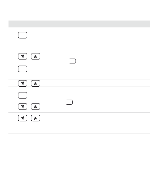
10 Accesso alla congurazione
Per parametri di congurazione vedi: (Par. 11 pag. 94)
Premere Eetto Eseguire
Su display 1 compare
con la 1^cifra lampeggiante,
mentre sul display 2 compare
pass
1
SET
per 3 sec.
Si modica la cifra lampeg-
2
o
SET
3
per conferma
4
o
SET
+
5
o
o
6
Contemporaneamente
** Con 1 su questa word, si annu llano gli ee tti della scrit tura su tutti gl i indirizzi M odbus da 3001
a 3022. Il controll o ritorna al regola tore.
92 - CN245 - Manuale d’uso
giante si passa alla successiva
con il tasto
Su display 1 compare il primo parametro e sul secondo
il valore.
Scorre i parametri
Si incrementa o decrementa
il valore visualizzato premen-
SET
do prima
freccia.
Fine variazione parametri di
congurazione.
Il regolatore esce dalla programmazione.
0000
SET
e poi un tasto
Inserire la p assword
Inserire il nuovo dato che
verrà salvato al rilascio
dei tasti. Per variare un
altro parametro tornare
al punto 4
1234
Page 93
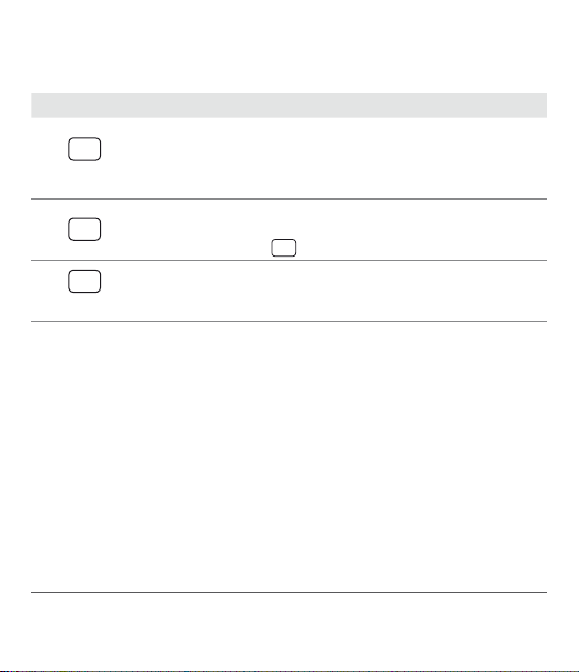
10.1 Caricamento valori di default
Questa procedura permette di ripristinare le impostazioni di fabbrica dello
strumento.
Premere Eetto Eseguire
Su display 1 compare
con la 1^cifra lampeggiante,
mentre sul display 2 compare
pass
1
SET
per 3 sec
Si modica la cifra lampeg-
SET
2
giante si passa alla successiva con il tasto
SET
3
per conferma
*** I parametri mo dicati usando gli ind irizzi seriali dal 4 001 al 4072, vengono salvati i n eeprom
solamente d opo 10” dall’ultim a scrittura di uno de i parametri.
Lo strumento carica le
impostazioni di fabbrica e
si riavvia
0000
Inserire la p assword
SET
9999
Manuale d’uso - CN245 - 93
Page 94

11 Tabella parametri di congurazione
1 C.out Command Output
selezione tipo uscita di comando (vedi tabelle sot tostanti)
c. o1
Default (necessario per utilizzo funzione di ritrasmissione di
processo e set con uscita Volt / mA)
c. o2
Comando su uscita relè Q2
c.SS r
Comando in tensione per SSR
c. uA L.
Comando servo-valvole a loop aperto
c.4 . 2 0
Comando con segnale 4...20 mA
c.0.20
Comando con segnale 0...20 mA
c.0.10
Comando con segnale 0...10 V
14
14
14
13
COMANDO ALLARME 1 ALLARME 2
CN245-R1R2F3C4
c. o1
c. o2
c.SS r
c. uA L.
c.4 . 2 0
c.0.20
c.0.10
13
Non impos tare mai se si utilizza la f unzione di ritrasmissio ne del processo.
94 - CN245 - Manuale d’uso
Q1 Q2 SSR
Q2 Q1 SSR
SSR Q1 Q2
Q1 (ap ri)
Q2 (chiudi)
4 ... 20 mA Q1 Q2
0 ... 20 mA Q1 Q2
0 ... 10 mV Q1 Q2
SSR -
Page 95

2 SEN . Sensor
Congurazione ingresso analogico
Tc.K
Tc- K (Default) -260 °C ... 1360 °C
Tc. s
Tc-S -40 °C ... 1760 °C
Tc. r
Tc-R -40 °C ... 1760 °C
Tc. j
Tc-J -200 °C ... 1200 °C
Pt
Pt100 -200 °C ... 600 °C
P t1
Pt100 -200 °C ... 140 °C
ni
NI100 -60 °C ... 180 °C
n t c .1
NTC10K-β3435K -40 .. 125°C
n tc.2
NTC10K-OMEGA -40 .. 150°C
n tc.3
NTC2252-OMEGA -40 .. 150°C
Ptc
PTC1K -50 °C ... 150 °C
Pts
Pt500 -100 °C ... 600 °C
P t1 k
Pt1000 -100 °C ... 60 0 °C
0 .1 0
0 ... 10 Volt
0.20
0 ... 20 mA
4.20
4 ... 20 mA
0.4 0
0 ... 40 mVolt
P o t .1
Potenziometro max. 6 KOhm (Par. 8 pag. 79)
Po t.2
Potenziometro max. 150 KOhm (Par. 8 pag. 79)
t.A.
T.A. con secondario 50 mA
d . P. Decimal Point
3
Seleziona il tipo di decimale visualizzato
0
Default
0.0
1 Decimale
0.00
2 Decimali
0.000
3 Decimali
Manuale d’uso - CN245 - 95
Page 96

4 Lo .L.S . Lower Limit Setpoint
Limite inferiore impostabile per il setpoint
-999 .. +9999 [digit
u p .L. S. Upper Limit Setpoint
5
Limite superiore impostabile per il setpoint
-999 .. +9999 [digit
14
] (gradi.decimi per sensori di temperatura), Default: 0.
14
] (gradi.decimi per sensori di temperatura),
Default: 1750.
Lo L.i Lower Linear Input
6
Limite inferiore range AN1 solo per normalizzati. Es: con ingresso 4...20 mA
questo parametro assume il valore associato a 4 mA
-999 bis +9999 [digit
u p .L.i . Upper Linear Input
7
14
], Default: 0.
Limite superiore range AN1 solo per normalizzati. Es: con ingresso 4...20 mA
questo parametro assume il valore associato a 20 mA
-999 bis +9999 [digit
La t c. Latch On Funct ion
8
14
], Default: 1000.
Impostazione automatica dei limiti per ingressi normalizzati e potenziometri. (Par. 8 pag. 79)
di s .
Disabled (Default)
std .
Standard
u.0 st.
Virtual zero stored
u . 0i n
Virtual zero initialized
dYn .L
Permette di superare i limiti inferiore e superiore se in ingresso ci
sono valori esterni al 0/4 .. 20mA o 0 .. 10V.
96 - CN245 - Manuale d’uso
Page 97

9 o . cA L. Oset Calibration
Calibrazione oset. Valore che si somma o sottrae al processo visualizzato
(es: normalmente corregge il valore di temperatura ambiente).
-999 .. +1000 [digit
-200.0 .. +100.0 (gradi.decimi per sensori di temperatura),
Default 0.0.
10
G. cAL. Gain Calibration
Calibraz ione guadagno AI1. Valore che si moltiplica al pro cesso per eseguire
calibrazione sul punto di lavoro.
-99.9% .. +100.0% (Default = 0.0)
es: per correggere la scala di lavoro da 0...1000°C che visualizza 0...1010°C,
ssare il parametro a -1.0
11
Act. t. Ac tion type
Tipo di regolazione
Heat
Caldo (N.A.) (Default)
coo L
Freddo (N.C.)
H.o.o.S.
Blocca comando sopra SPV. Es: uscita di comando disabilitata al
12
c. re. Command Rearmament
Tipo di riarmo del contatto di comando (sempre automatico in funzionamen to P.I .D. ).
a re.
Riarmo automatico (Default)
m re.
Reset manuale
m re.s .
Reset manuale memorizzato (mantiene lo stato del relè anche
14
] per sensori normalizzati e potenziometri.
raggiungimento del setpoint anche con valore di P.I.D. diverso da
zero.
dopo un eventuale mancanza di alimentazione)
Manuale d’uso - CN245 - 97
Page 98

13 c. S. e. Command State Error
Stato del contatto per l’uscita di comando in caso di errore
c. o.
Contatto aperto (Default)
c. c.
Contatto chiuso
14
c. Ld. Command Led
Denisce lo stato del led OUT1 in corrispondenza del relativo contatto
c. o.
Acceso a contatto aperto
c. c.
Acceso a contatto chiuso (Default)
15
c. HY. Command Hysteresis
Isteresi in ON/OFF o banda mor ta in P.I.D.
-999 .. +999 [digit14] (gradi.decimi per sensori di temperatura), Default 0.0.
16
c. de . Command Delay
Ritardo comando (solo in funzionamento ON/OFF). In caso di servo valvola
funziona anche in P.I.D. e rappresenta il ritardo tra l’apertura e la chiusura
dei due contatti.
-180 . . +180 secondi (decimi di secondo in caso di servo valvola).
Negativo: ritardo in fase di spegnimento.
Positivo: ritardo in fase di accensione. Default: 0.
17
c. s. p. Command Setpoint Protection
Consente o meno di variare il valore del setpoint di comando
free
Modicabile dall’utente (Default)
Lo c k
Protetto
18
p. b. Proportional Band
Banda prop orzionale. Inerzia del processo in unità (es: se temperatura in °C)
0 ON / OFF se
1-9999 [digit14] (gradi per sensori di temperatura)
14
La visualizzazione del punto decimale dipende dall’impostazione del parametro
e del parame tro
98 - CN245 - Manuale d’uso
t.i .
uguale a 0 (Default)
d. p.
sen.
Page 99

19 t.i . Integral Time
Tempo integrale. Inerzia del processo in secondi
0.0-999.9 secondi (0 = integrale disabilitato), Default: 0.
20
t. d . Derivative Time
Tempo derivativo. Normalmente ¼ del tempo integrale
0.0-999.9 secondi (0 = derivativo disabilitato), Default: 0.
21
t. c. Cycle Time
Tempo di ciclo (per P.I.D. su teleruttore 10 / 15 sec, per P.I.D. su SSR 1 sec.) o
tempo servo-motore (valore dichiarato da produttore)
1-300 secondi, Default: 10.
22
o . Po L. Output Power Limit
Seleziona il valore massimo per la percentuale dell’uscita di comando 0 ..
100%, Default: 100%.
Es: con
c.out
di comando può variare da un minimo di 0 V al massimo di 9 V.
23 A L .1 Alarm 1
Selezione allarme 1. L’intervento dell’allarme è associato a AL1.
(Par. 12 pag. 112)
di s .
A. AL.
b . AL.
H. d .A L.
L. d . A L.
A. c.AL.
s t. A L.
coo L
L. b . A.
Es: controlla lo stato dei contattori / SSR o delle resistenze
selezionato 0...10 V e impostazione su
Disabilitato (Default)
Assoluto / soglia, riferito al processo
Allarme di banda
Allarme di deviazione superiore
Allarme di deviazione inferiore
Assoluto / soglia, riferito al setpoint di comando
Allarme di stato (attivo in Run / Star t)
Azione freddo (cooling) (Par. 8. 3 pag. 83)
Allarme di stato “controllo carico” (Loop Break Alarm)
o . Po L.
al 90%, l’uscita
Manuale d’uso - CN245 - 99
Page 100

24 A . I. 5 . o . Alarm 1 State Ou tput
Contatto uscita allarme 1 e tipo intervento.
n . o . s.
(N.O. Start) Normalmente aperto, operativo dallo start (Default)
n . c. s.
(N.C . Start) Normalmente chiuso, operativo dallo start
n . o . t.
(N .O. Threshold) Nor malmente aperto, o perativo al raggi ungimen-
to dell’allarme
n . c. t.
(N.C . Threshold) Norma lmente chiuso, operati vo al raggiungimen-
to dell’allarme
25 a1 . r e . Alarm 1 Rearmament
Tipo di reset del contatto dell’allarme 1
a re.
Automatic Reset (Default)
m re.
Reset manuale (riarmo/reset manuale da tastiera)
m re.s .
Reset Manuale memorizzato (mantiene lo stato del relè anche
dopo un eventuale mancanza di alimentazione)
a .1 . s . e . Al arm 1 State Reset
26
Stato del contatto per l’uscita di allarme 1 in caso di errore
c. o.
Contatto aperto (Default)
c. c.
Contatto chiuso
a.1.Ld. Alarm 1 Led
27
Denisce lo stato del led OUT2 in corrispondenza del relativo contatto
c. o.
Acceso a contatto aperto
c. c.
Acceso a contatto chiuso (Default)
15
All’accensio ne, l’uscita è inibita se lo s trumento è in condizio ne di allarme. Si at tiva solo
quando rientrato dalla condizione d’allarme, questa si ripresenta.
100 - CN245 - Manuale d’uso
15
15
SET
 Loading...