

Page 1
Operating Manual | Bedienungsanleitung
English Deutsch
ClipX
Page 2

Hottinger Baldwin Messtechnik GmbH
Im Tiefen See 45
64293 Darmstadt
Tel. +49 6151 803-0
Fax +49 6151 803-9100
[email protected]
www.hbm.com
Mat.:
DVS: A04643_04_X00_00 HBM: public
04.2019
© Hottinger Baldwin Messtechnik GmbH.
Subject to modifications.
All product descriptions are for general information only.
They are not to be understood as a guarantee of quality or
durability.
Änderungen vorbehalten.
Alle Angaben beschreiben unsere Produkte in allgemeiner
Form. Sie stellen keine Beschaffenheits- oder Haltbarkeitsgarantie dar.
Page 3
Operating Manual | Bedienungsanleitung
English Deutsch
ClipX
Page 4

Contents Page
1 Safety instructions . . . . . . . . . . . . . . . . . . . . . . . . . . . . . . . . . . . . . . . 5
2 Symbols on the device . . . . . . . . . . . . . . . . . . . . . . . . . . . . . . . . . . . . 9
3 Overview . . . . . . . . . . . . . . . . . . . . . . . . . . . . . . . . . . . . . . . . . . . . . . 11
4 ClipX device types, scope of supply. . . . . . . . . . . . . . . . . . . . . . . . 13
4.1 Device types . . . . . . . . . . . . . . . . . . . . . . . . . . . . . . . . . . . . . . . . . . . . 13
4.2 Scope of supply . . . . . . . . . . . . . . . . . . . . . . . . . . . . . . . . . . . . . . . . . 15
4.3 Dimensions . . . . . . . . . . . . . . . . . . . . . . . . . . . . . . . . . . . . . . . . . . . . . 16
5 Mounting . . . . . . . . . . . . . . . . . . . . . . . . . . . . . . . . . . . . . . . . . . . . . . 17
5.1 Mounting on a support rail . . . . . . . . . . . . . . . . . . . . . . . . . . . . . . . . . 17
5.2 Dismounting from a support rail . . . . . . . . . . . . . . . . . . . . . . . . . . . . . 18
5.3 Other mounting options. . . . . . . . . . . . . . . . . . . . . . . . . . . . . . . . . . . . 19
6 Electrical connections, LEDs. . . . . . . . . . . . . . . . . . . . . . . . . . . . . . 21
6.1 Functionality (block diagram) . . . . . . . . . . . . . . . . . . . . . . . . . . . . . . . 21
6.2 Shielding and grounding design . . . . . . . . . . . . . . . . . . . . . . . . . . . . . 23
6.3 Available connections and LEDs. . . . . . . . . . . . . . . . . . . . . . . . . . . . . 24
6.4 Health-Monitoring, LEDs. . . . . . . . . . . . . . . . . . . . . . . . . . . . . . . . . . . 26
6.5 Connecting the supply voltage . . . . . . . . . . . . . . . . . . . . . . . . . . . . . .34
6.6 Connecting transducers . . . . . . . . . . . . . . . . . . . . . . . . . . . . . . . . . . . 35
6.6.1 Strain gage full and half bridge, voltage-fed piezo-resistive
sensors . . . . . . . . . . . . . . . . . . . . . . . . . . . . . . . . . . . . . . . . . . . . . . . . 36
6.6.2 Strain gage full bridge for applications in areas with potentially
explosive atmospheres . . . . . . . . . . . . . . . . . . . . . . . . . . . . . . . . . . . . 41
6.6.3 Potentiometric transducer . . . . . . . . . . . . . . . . . . . . . . . . . . . . . . . . . . 42
6.6.4 Temperature measurement by Pt100 . . . . . . . . . . . . . . . . . . . . . . . . . 43
6.6.5 Voltage source (±10 V) . . . . . . . . . . . . . . . . . . . . . . . . . . . . . . . . . . . .44
6.7 Use TEDS . . . . . . . . . . . . . . . . . . . . . . . . . . . . . . . . . . . . . . . . . . . . . . 47
6.8 Connecting the digital inputs and outputs . . . . . . . . . . . . . . . . . . . . . . 49
6.9 Connecting the analog output . . . . . . . . . . . . . . . . . . . . . . . . . . . . . . . 51
6.10 Using multiple ClipX devices, ClipX bus . . . . . . . . . . . . . . . . . . . . . . . 52
6.11 Synchronizing multiple ClipX CF amplifiers . . . . . . . . . . . . . . . . . . . . 54
6.12 Signal phase delays within the ClipX and over the ClipX bus. . . . . . . 56
2 A04643_04_X00_00 HBM: public ClipX
Page 5

7 Starting up the ClipX . . . . . . . . . . . . . . . . . . . . . . . . . . . . . . . . . . . . 63
7.1 Power-up and operating behavior. . . . . . . . . . . . . . . . . . . . . . . . . . . . 63
7.2 Connecting a web browser to the ClipX . . . . . . . . . . . . . . . . . . . . . . . 64
7.2.1 No device found? . . . . . . . . . . . . . . . . . . . . . . . . . . . . . . . . . . . . . . . . 67
7.2.2 Possible cases and their effects when connected via Ethernet . . . . . 69
7.2.3 Set Ethernet address of PC . . . . . . . . . . . . . . . . . . . . . . . . . . . . . . . . 69
7.2.4 Resetting Ethernet network settings (DHCP), enabling fixed IP
address . . . . . . . . . . . . . . . . . . . . . . . . . . . . . . . . . . . . . . . . . . . . . . . . 72
7.3 User Management . . . . . . . . . . . . . . . . . . . . . . . . . . . . . . . . . . . . . . . 74
7.4 Setting the ClipX using a web browser . . . . . . . . . . . . . . . . . . . . . . . . 76
7.4.1 Assistant to measure sensors. . . . . . . . . . . . . . . . . . . . . . . . . . . . . . . 76
7.4.2 Calculation functions. . . . . . . . . . . . . . . . . . . . . . . . . . . . . . . . . . . . . . 78
7.5 Using parameter sets . . . . . . . . . . . . . . . . . . . . . . . . . . . . . . . . . . . . . 94
7.6 Device storage (Device cloning) . . . . . . . . . . . . . . . . . . . . . . . . . . . . . 95
8 Operation via Ethernet/OPC UA. . . . . . . . . . . . . . . . . . . . . . . . . . . . 99
8.1 Accessing via standard Ethernet and object dictionary . . . . . . . . . . . 99
8.2 Operation and content of the ClipX-FIFO . . . . . . . . . . . . . . . . . . . . . 103
8.3 Using OPC UA . . . . . . . . . . . . . . . . . . . . . . . . . . . . . . . . . . . . . . . . . 108
9 Operation via fieldbus . . . . . . . . . . . . . . . . . . . . . . . . . . . . . . . . . . 113
9.1 Connecting the fieldbus . . . . . . . . . . . . . . . . . . . . . . . . . . . . . . . . . . 113
9.2 Data types used by the ClipX . . . . . . . . . . . . . . . . . . . . . . . . . . . . . . 115
9.3 Data transfer from the controller to the ClipX . . . . . . . . . . . . . . . . . . 116
9.4 Data transfer from the ClipX to the controller . . . . . . . . . . . . . . . . . . 119
9.5 Settings for the fieldbuses. . . . . . . . . . . . . . . . . . . . . . . . . . . . . . . . . 122
9.5.1 Settings for PROFINET. . . . . . . . . . . . . . . . . . . . . . . . . . . . . . . . . . . 122
9.5.3 Settings for EtherNet/IP™. . . . . . . . . . . . . . . . . . . . . . . . . . . . . . . . . 123
9.5.4 Settings for PROFIBUS . . . . . . . . . . . . . . . . . . . . . . . . . . . . . . . . . . 124
9.6 Flags and status bits . . . . . . . . . . . . . . . . . . . . . . . . . . . . . . . . . . . . . 142
9.6.1 Measured value status: List of status bits . . . . . . . . . . . . . . . . . . . . . 142
9.6.2 System status: List of status bits. . . . . . . . . . . . . . . . . . . . . . . . . . . . 144
9.6.3 TEDS status: List of status bits . . . . . . . . . . . . . . . . . . . . . . . . . . . . . 146
9.6.4 Digital flags: List of I/O flags (I/O status). . . . . . . . . . . . . . . . . . . . . . 147
9.6.5 The control word . . . . . . . . . . . . . . . . . . . . . . . . . . . . . . . . . . . . . . . . 148
ClipX A04643_04_X00_00 HBM: public 3
Page 6

9.7 Object dictionary . . . . . . . . . . . . . . . . . . . . . . . . . . . . . . . . . . . . . . . . 149
9.7.1 How do you access the ClipX objects?. . . . . . . . . . . . . . . . . . . . . . . 151
9.7.2 Examples of object access via the fieldbus . . . . . . . . . . . . . . . . . . . 155
9.7.4 Measuring channel objects . . . . . . . . . . . . . . . . . . . . . . . . . . . . . . . . 169
9.7.5 I/O objects. . . . . . . . . . . . . . . . . . . . . . . . . . . . . . . . . . . . . . . . . . . . . 176
9.7.7 Objects of the ClipX functions. . . . . . . . . . . . . . . . . . . . . . . . . . . . . . 197
9.7.8 CiA 404 objects. . . . . . . . . . . . . . . . . . . . . . . . . . . . . . . . . . . . . . . . . 200
9.7.9 List of signal references . . . . . . . . . . . . . . . . . . . . . . . . . . . . . . . . . . 203
10 Calibration certificates . . . . . . . . . . . . . . . . . . . . . . . . . . . . . . . . . . 207
11 Updating the firmware . . . . . . . . . . . . . . . . . . . . . . . . . . . . . . . . . . 208
12 Diagnostics and error rectification, FAQs . . . . . . . . . . . . . . . . . . 211
12.1 Possible errors . . . . . . . . . . . . . . . . . . . . . . . . . . . . . . . . . . . . . . . . . 211
12.2 FAQs. . . . . . . . . . . . . . . . . . . . . . . . . . . . . . . . . . . . . . . . . . . . . . . . . 213
13 Technical support . . . . . . . . . . . . . . . . . . . . . . . . . . . . . . . . . . . . . . 217
14 Maintenance . . . . . . . . . . . . . . . . . . . . . . . . . . . . . . . . . . . . . . . . . . 219
15 Disposal . . . . . . . . . . . . . . . . . . . . . . . . . . . . . . . . . . . . . . . . . . . . . . 221
16 Index. . . . . . . . . . . . . . . . . . . . . . . . . . . . . . . . . . . . . . . . . . . . . . . . . 223
4 A04643_04_X00_00 HBM: public ClipX
Page 7

Safety instructions
1 Safety instructions
Read this operating manual before operating the device for the first time. Any
persons assigned to install, commission, operate or maintain the device must
have read at least the sections of the operating manual of relevance to them.
The operating manual forms part of the product. Keep it in a safe place so that it
is permanently accessible to all users. If you pass the device on to a third party,
always pass it on together with the relevant documents.
Intended use
The ClipX amplifier system is to be used exclusively for measurement tasks and
directly related control tasks (automation systems). Use for any purpose other
than the above is deemed to be non-designated use. In the interests of safety,
the device should only be operated as described in the operating manual.
The device may only be powered by a safety extra low voltage (DIN EN 61558
or VDE 0570, Safety of transformers, reactors, power supply units and combinations thereof). The supply voltage must be between 10 V and 30 V (DC).
Conditions at the place of installation
• Protect the device from direct contact with water.
• Protect the ClipX from moisture and dampness or weather such as rain,
snow, etc.
• Do not expose the device to direct sunlight.
• Please observe the permissible maximum ambient temperatures stated in
the specifications.
• The permissible relative humidity at 31 °C is 95 % (non condensing); linear
reduction up to 50 % at 40 °C.
• It is safe to operate the ClipX up to an altitude of 2000 meters.
Conversions and modifications
The device must not be modified from the design or safety engineering point of
view except with our express agreement. In particular, any repair or soldering
work on motherboards is prohibited. The device must not be opened. The prod-
ClipX A04643_04_X00_00 HBM: public 5
Page 8

Safety instructions
uct is delivered from the factory with a fixed hardware and software configuration. Changes can only be made within the possibilities documented in the operating manual.
Qualified personnel
This device is only to be installed and used by qualified personnel (electricians
or persons trained in electrical engineering), strictly in accordance with the
safety regulations listed here. This includes personnel who meet at least one of
the three following requirements, depending on their assigned tasks:
• Knowledge of the safety concepts of measurement and automation technol-
ogy is a requirement and as project personnel, they must be familiar with
these concepts.
• As measurement or automation system operating personnel, they have
been instructed how to use the equipment. They are familiar with the operation of the equipment and technologies described in this document.
• As commissioning engineers or service engineers, you have successfully
completed the training to repair the automation systems. You are also
authorized to operate, ground and label circuits and equipment in accordance with safety engineering standards.
Residual dangers
The ClipX system is a state-of-the art unit and as such is reliable. The scope of
supply and performance of the ClipX system covers only a small area of measurement technology however. In addition, equipment planners, installers and
operators should plan, implement and respond to the safety engineering considerations of measurement technology in such a way as to minimize residual dangers. For example, automation equipment and devices must be designed in
such a way that adequate protection or locking against unintentional actuation is
provided (e.g. access controls, password protection, etc.). When devices are
working in a network, these networks must be designed in such a way that malfunctions in individual nodes can be detected and shut down. Safety precautions must be taken both in terms of hardware and software, so that a line break
or other interruptions to signal transmission do not cause undefined states or
loss of data in the automation device.
6 A04643_04_X00_00 HBM: public ClipX
Page 9

Safety instructions
Safety notice used in this document
Note
This symbol draws your attention to a situation in which failure to comply with
safety requirements may result in damage to property.
ClipX A04643_04_X00_00 HBM: public 7
Page 10

Safety instructions
8 A04643_04_X00_00 HBM: public ClipX
Page 11
2 Symbols on the device
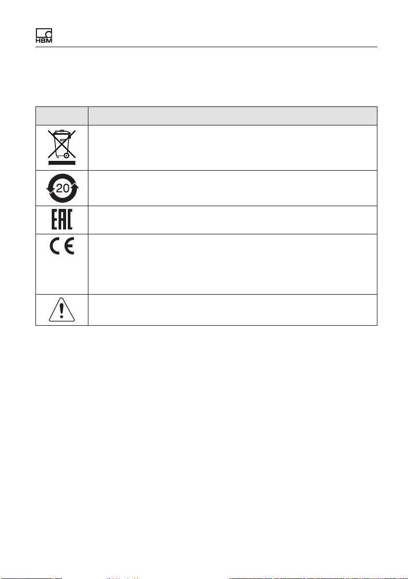
Symbol Meaning
Statutory waste disposal mark, see “Disposal” on page 221.
Statutory mark of compliance with emission limits in electronic equipment supplied to China
Marking certifying approval for sale of the device in the Russian Federation.
CE mark
The CE mark enables the manufacturer to guarantee that the product
complies with the requirements of the relevant EC directives. The declaration of conformity can be found on the HBM website
https://www.hbm.com under HBMdoc.
Read and note the information given in this manual.
Symbols on the device
ClipX A04643_04_X00_00 HBM: public 9
Page 12

Symbols on the device
10 A04643_04_X00_00 HBM: public ClipX
Page 13

Overview
3 Overview
Make sure you always have, and are using, the documentation version matching your device. After a firmware update, for example, you can download the
current version of the full documentation from the HBM website:
https://www.hbm.com/ClipX. To read this documentation you need the Adobe
Acrobat Reader. You can download the Acrobat Reader free of charge from the
Adobe website.
About ClipX
By buying a ClipX measuring amplifier, you have chosen a high-quality HBM
measurement system that is compact, powerful and variable. You can connect
the ClipX via the standard Ethernet port to a PC, and parameterize and control
the device via its internal web server. You can connect to an automation system
via the digital and analog inputs/outputs and/or via one of the fieldbus interfaces
2)
PROFIBUS®, PROFINET®, EtherNet/IP™1) or EtherCAT
device type). One input per device is provided for different sensors (strain gage,
voltage, current, potentiometer or Pt100), and you can connect sensors with
zero-wire TEDS or 1-wire TEDS. The device additionally features a peak value
memory, instantaneous value memory, limit value switches, and six calculated
channels, as well as offering the facility to display one signal from each of up to
five additional devices and forward the signals to the interfaces. The ClipX is
normally mounted on a support rail; the mounting materials are supplied.
®
(depending on
The ClipX documentation
• Quick Start Guide (supplied)
• This manual in PDF format
• Data sheet listing the technical data
• Online help on the device's internal web server
1)
EtherNet/IP™ is a trademark of ODVA Inc. For more information regarding ODVA, visit
www.odva.org.
2)
EtherCAT® is a registered brand and patented technology, licensed by Beckhoff Automation
GmbH, Germany.
ClipX A04643_04_X00_00 HBM: public 11
Page 14
Overview
Contents of this manual
This manual has a table of contents at the beginning. The index at the end of the
manual enables you to search for specific terms. The most frequently asked
questions are summarized in section “FAQs” on page 213.
All the marks mentioned in this manual are the property of their respective owners.
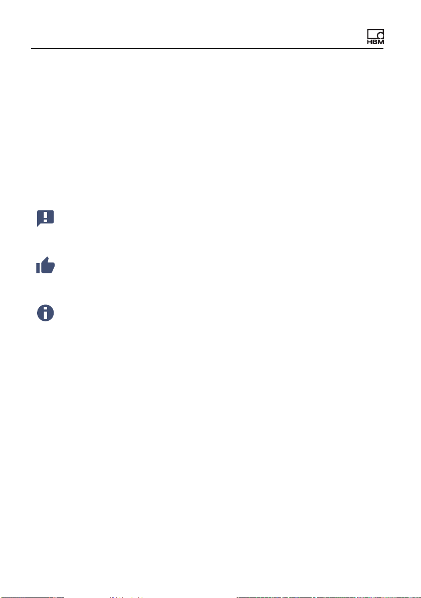
Symbols used in this manual
See also “Safety instructions” on page 5.
Important: This symbol indicates an important detail or a special feature.
Paragraphs with this symbol provide a tip or explain an interesting feature.
Paragraphs marked by this symbol contain additional information.
12 A04643_04_X00_00 HBM: public ClipX
Page 15

ClipX device types, scope of supply
4 ClipX device types, scope of supply
The ClipX is mounted directly on a support rail, though other mounting methods
are also possible. The ClipX is supplied as standard with easy-fit push-in type
plug terminals. You can also use screw-type plug terminals from Phoenix Contact – see “Electrical connections, LEDs” on page 21.
You can connect strain gage full or half bridges, voltage-fed piezo-resistive sensors, current or voltage sensors and currents or voltages, potentiometer transducers or Pt100s to the transducer connector. Two freely configurable digital
input/outputs and an analog output for current or voltage are additionally available.
Important: All basic settings are made via the web server integrated
into the ClipX and your web browser. The web server includes its own
help, which explains all the ClipX settings. Depending on the design,
you can also connect the ClipX to various fieldbuses.
4.1 Device types
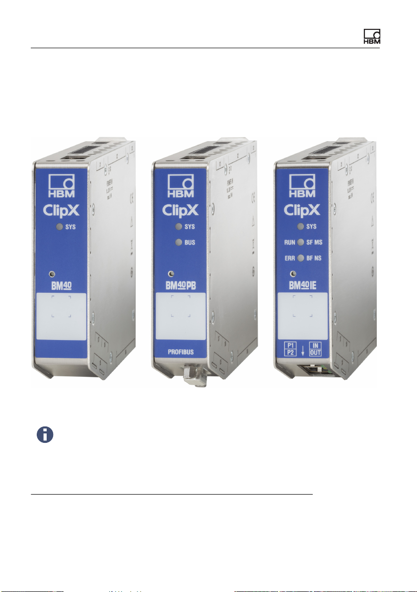
The ClipX comes in three different design versions. All the design versions feature the same sensor inputs, two freely configurable digital input/outputs, and an
analog output switchable for current (4 … 20 mA) or voltage (±10 V):
1. BM40
This version does not include a fieldbus.
2. BM40PB
This version includes a PROFIBUS® interface.
ClipX A04643_04_X00_00 HBM: public 13
Page 16
ClipX device types, scope of supply
3. BM40IE
You can operate this version with a one of the interfaces for PROFINET®,
2)
EtherNet/IP™1) or EtherCAT
®
interface. The interfaces can be switched
using the software.
Fig. 1: The ClipX device types from left to right: BM40, BM40PB and BM40IE
To aid the design process, pre-compiled ePLAN macros (licensefree) and 3D-STEP files are available free of charge at
https://www.hbm.com/ClipX.
1)
EtherNet/IP™ is a trademark of ODVA Inc. For more information regarding ODVA, visit
www.odva.org.
2)
EtherCAT® is a registered brand and patented technology, licensed by Beckhoff Automation
GmbH, Germany.
14 A04643_04_X00_00 HBM: public ClipX
Page 17

ClipX device types, scope of supply
4.2 Scope of supply
• ClipX with mounted support rail holder.
• Bag containing three plug terminals, ordering number 1-CON-S1019 for
sensor connection (13-pin), supply, digital I/O and ClipX bus (12-pin) as well
as the analog output (3-pin). You can also order this plug terminal set separately.
• Shield connection clamp ME-SAS MINI - 2200456 from PHOENIX , HBM
order no. 1-CON-A1023. You can order more clamps from HBM as required.
• A Quick Start Guide with safety instructions (a4838).
You can download a full operating manual as well as additional information resources from the HBM website:
https://www.hbm.com/ClipX. Pre-compiled ePLAN macros (license-
free) and 3D-STEP files to aid the design process are also available
to download. To read this documentation you need the Adobe Acrobat Reader. You can download the Acrobat Reader free of charge
from the Adobe website.
ClipX A04643_04_X00_00 HBM: public 15
Page 18
ClipX device types, scope of supply
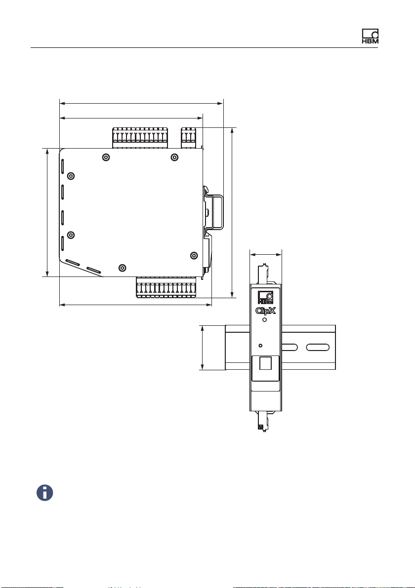
4.3 Dimensions
100
127.7
111. 7
132.6
25
118.6
35
Fig. 2: ClipX dimensions when mounted on support rail (DIN rail 35 mm to DIN
EN 60715) with 16 mm depth, all measures in mm
To aid the design process, pre-compiled ePLAN macros (licensefree) and 3D-STEP files are available free of charge at
https://www.hbm.com/ClipX.
16 A04643_04_X00_00 HBM: public ClipX
Page 19
Mounting
5 Mounting
The ClipX is designed for mounting on a support rail (35 mm DIN rail to DIN
EN 60715). You can choose different mounting methods if you want though. The
support rail on which you mount the ClipX may be 8.5 or 16 mm deep.
Important: You must ground the support rail.
5.1 Mounting on a support rail
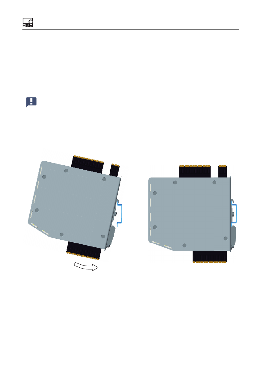
Fig. 3: Mounting on a support rail
1. Hang the ClipX from the top edge of the support rail.
2. Push the ClipX onto the support rail in the direction of the arrow as shown in
the picture.
The clip at the bottom secures the ClipX by a spring.
ClipX A04643_04_X00_00 HBM: public 17
Page 20
Mounting
5.2 Dismounting from a support rail
3
2
1
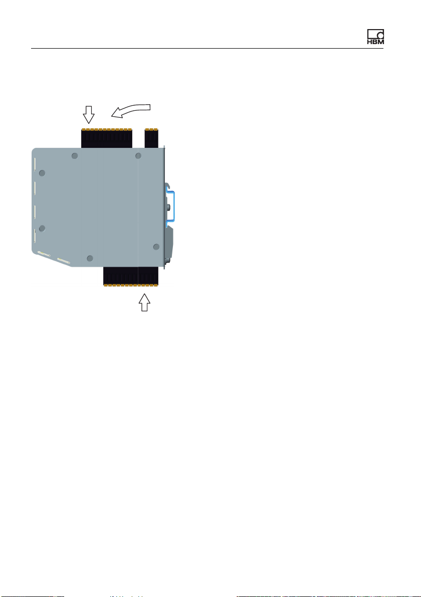
Fig. 4: Dismounting from a support rail
1. Push the ClipX up.
The spring mechanism allows you to release it from the top locator on the
support rail.
2. Tilt the ClipX forward, rotating it as you do so.
3. Detach the ClipX downwards.
18 A04643_04_X00_00 HBM: public ClipX
Page 21
Mounting
5.3 Other mounting options
Instead of using a support rail, you can mount the ClipX on a wall, for example,
using an appropriate bracket. To do so, make a mounting bracket to fit on the
back of the ClipX.
Important: The vents on the back must not be covered over. The minimum clearance between the back of the device and a wall in the area
of the vents is 8 mm.
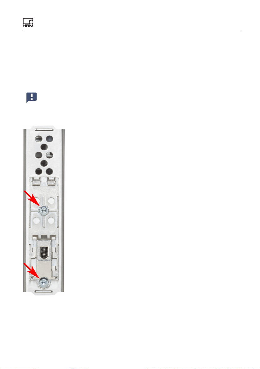
Fig. 5: Screws to remove the support rail mount
ClipX A04643_04_X00_00 HBM: public 19
Page 22

Mounting
Procedure
1. Use a size T10 Torx screwdriver to remove the screws indicated in the picture.
2. Keep the screws, because you should reuse them.
3. Make your mounting bracket.
The material should be about 1 to 2 mm thick, to enable you to reuse the
original (M3) screws. The space between the two screws is 43.7 mm.
4. Fix your mount either using the original screws or using M3 screws penetrating a maximum of 5 mm into the housing. Fasten the screws only hand-tight.
Important: You must ground the ClipX housing, such as by way of the
mount.
20 A04643_04_X00_00 HBM: public ClipX
Page 23

Electrical connections, LEDs
6 Electrical connections, LEDs
The ClipX features IP20 protection in accordance with EN 60529 (protection
against touch by fingers; protection against foreign bodies of Ø > 12 mm).
The ClipX is supplied as standard with easy-fit push-in terminals. But you can
also obtain screw-type terminals from Phoenix Contact (https://www.phoenix-
contact.com, BK = black variant), e.g.:
– MC 1.5/3-ST-3.5 BK for the analog output,
– MC 1.5/12-ST-3.5 BK for the power supply, digital I/O, ClipX bus and syn-
chronization of the TF amplifiers,
– MC 1.5/13-ST-3.5 BK for connection of sensors.
Other variants, such as with locking clips, are also available from Phoenix Con-
tact, e.g. MCVW 1.5/…, MCVR 1.5/…, FK-MCP 1.5/…
The clamping range of the plug terminals is 0.2 mm2 (AWG24) to 1.5 mm2
(AWG16). If you need to connect multiple wires to one terminal, adapt the wire
cross-sections accordingly. Use 10 mm wire end ferrules (without plastic collars)
to connect the wires to the terminals wherever possible.
The plug terminals can be protected against interchanging by the supplied coding pins. To do so, plug a coding pin into one of the slots in the device sockets
and remove the lug of the corresponding connection on the plug terminal.
To aid the design process, pre-compiled ePLAN macros (licensefree) and 3D-STEP files are available free of charge at
https://www.hbm.com/ClipX.
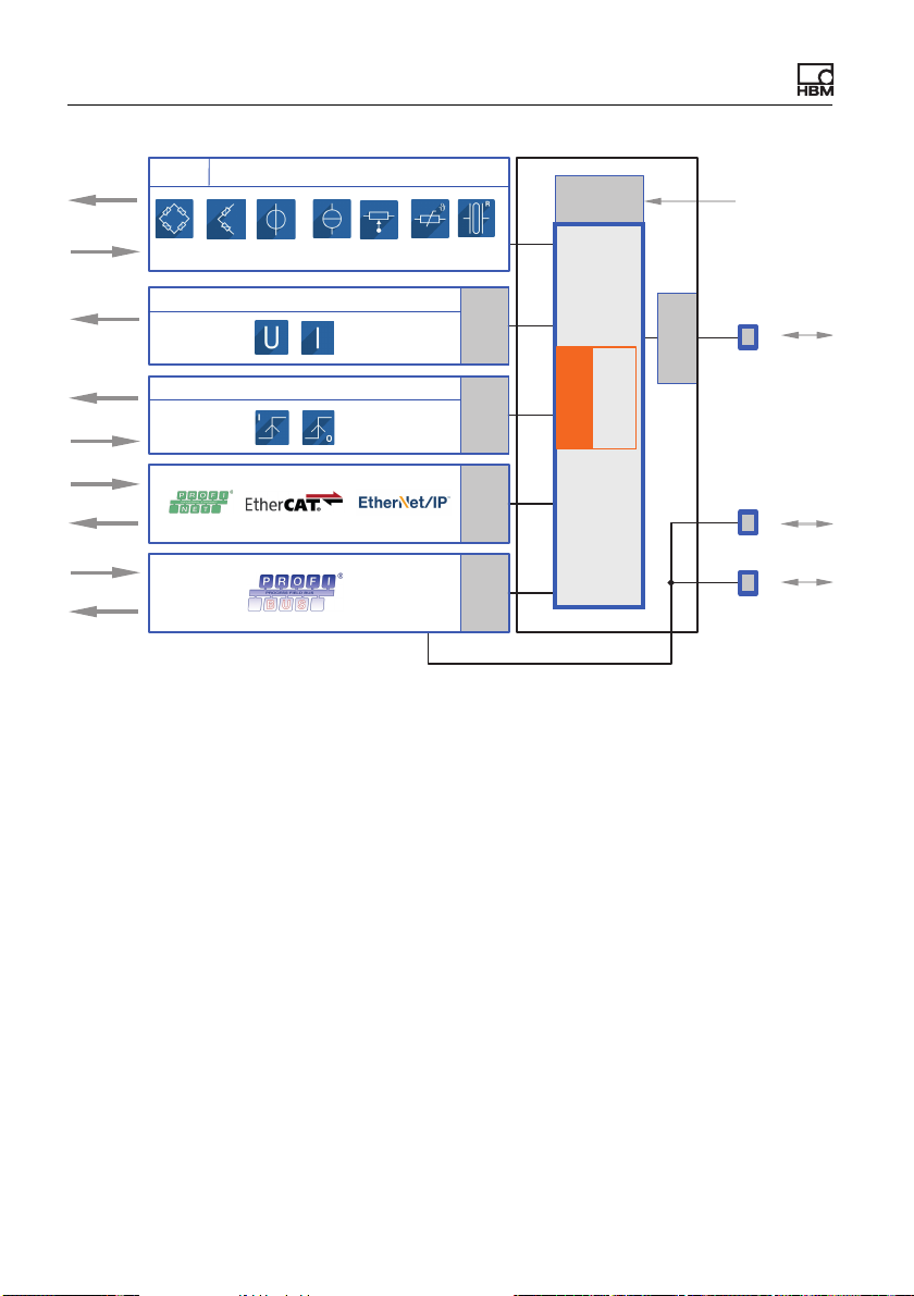
6.1 Functionality (block diagram)
The following diagram presents the functionality and interaction of the various
inputs and outputs of the ClipX. The electrical isolation of the various function
blocks is also shown: there is electrical isolation between the power supply and
all signal inputs and outputs.
ClipX A04643_04_X00_00 HBM: public 21
Page 24
Electrical connections, LEDs
Bridge
excitation
Signal
Signal
DO 1/2
DO GND
DI 1/2
DI GND
Signal
DC / CF
Transducer
TEDS
Analog output
Digital I/Os
isolation
Galvanic
isolation
Galvanic
isolation
Galvanic
Galvanic
isolation
CPU
FPU
Floating point
unit
isolation
Galvanic
ClipX SYNC
24 V
0 V
Ethernet
ClipX bus
Signal
isolation
Galvanic
Fig. 6: Function blocks and electrical isolation of the ClipX
Electrical isolation of the GND connections
The following connections are electrically isolated from each other:
• DI, GND (Ground) Digital-In: Reference potential for DI1 and DI2.
• X, GND ClipX bus: Reference potential for ClipX bus (CxA, CxB) and Sync;
on the BM40PB PROFIBUS-GND is also connected by this.
• AI, GND Analog-In: Reference potential for U-In and I-In; the adjacent measurement inputs for voltage and current.
• S GND for the inner shield on double-shielded cable; with 1-wire TEDS,
TEDS (–) is also connected here.
• AO, GND Analog-Out: Reference potential for the analog output.
22 A04643_04_X00_00 HBM: public ClipX
Page 25
Electrical connections, LEDs
6.2 Shielding and grounding design
The supply voltage connection, as well as the signal and sense leads, must be
installed in such a way that electromagnetic interference does not adversely
affect module functionality (HBM recommendation: “Greenline shielding design”
– see http://www.hbm.com/Greenline). Always connect the cable shield by the
shortest possible length to the plug terminals and, as far as possible, lay the
shield flat at the control cabinet inlet with shield connection clamps, e.g. type
SKS 8-SNS35 – 3062786 from Phoenix Contact – see illustration of shield
clamp.
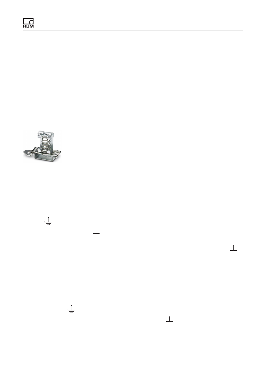
Fig. 7: Shield clamp for flat contacting of cable shields (example)
Double-shielded connecting cables, e.g. for sensors
We recommend using HBM cable Kab 7.5/00-2/2/2 wherever possible. The
cable is double-shielded and low in capacitance. When using double-shielded
cables, connect the outer shield only to the connection for the housing (ground
symbol , labeled “Outer cable shield” in the connection diagrams), not to one
of the GND connections ( ). In the case of control cabinets, also lay this shield
S
contacting on the cabinet – see illustration of shield clamp. Connect the inner
shields of the sensor cables to the connection labeled “Inner cable shield” ( ).
S
Use the shortest lines possible for the connections.
Applications in areas with potentially explosive atmospheres are exceptions.
There connect all cable shields to the potential equalization connection.
Single-shielded cables
Connect the shields of single-shielded cables to the connection for the housing
(ground symbol , labeled “Outer cable shield” or “Cable shield” in the connection diagrams), not to one of the GND connections ( ). In the case of control
S
ClipX A04643_04_X00_00 HBM: public 23
Page 26
Electrical connections, LEDs
cabinets, also lay this shield contacting on the cabinet – see illustration of shield
clamp.
Grounding
Important: You must ground the support rail on which you mount the
ClipX. If you want to mount the ClipX in a different way, such as on a
wall, you must ground the housing by way of the mount.
6.3 Available connections and LEDs
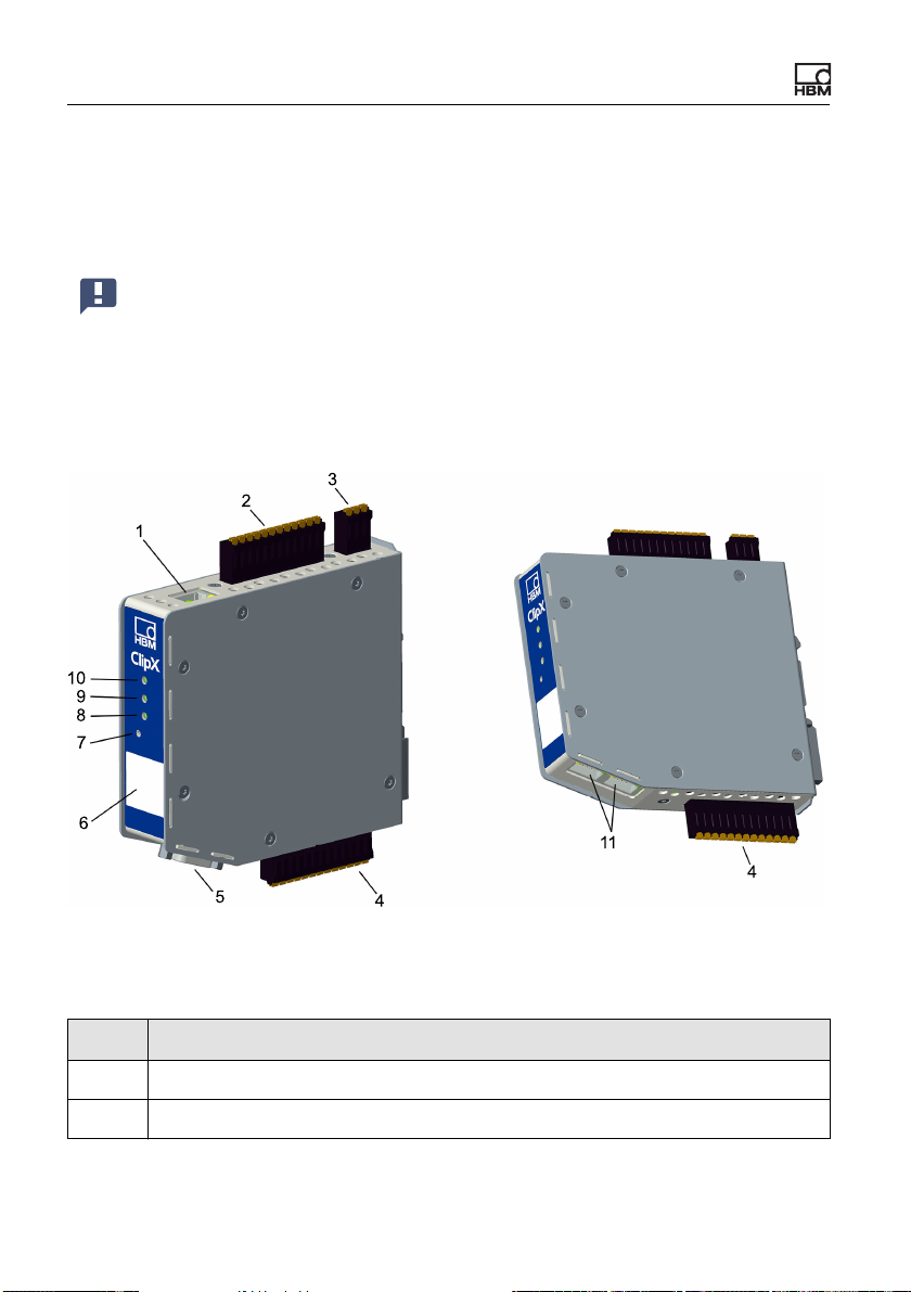
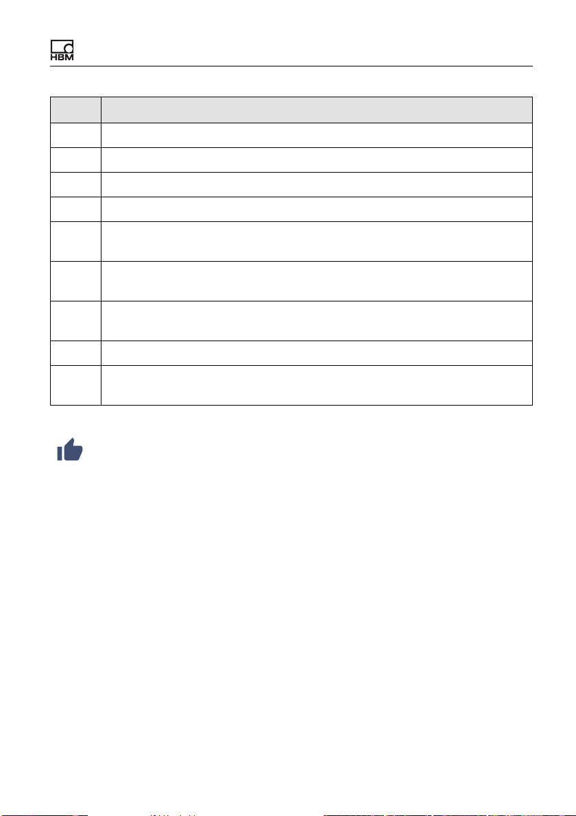
Fig. 8: Locations of the connections and LEDs; the connector designations X1
to X7 are imprinted on the housing; for meanings see table.
No. Description
1 X1: Ethernet port
2 X2: Power supply, Digital I/O, ClipX bus
24 A04643_04_X00_00 HBM: public ClipX
Page 27
No. Description
3 X3: Analog output
4 X4: Transducer connection, TEDS
5 X5: Fieldbus, here PROFIBUS (only BM40PB)
6 HBM calibration label and free labeling space
Reset button, see “User Management” on page 74, “Resetting Ethernet net-
7
work settings (DHCP), enabling fixed IP address” on page 72
Fieldbus LED 1, only BM40IE; EtherCAT: ERR, PROFINET: BF, Ether-
8
Net/IP™: NS
Fieldbus LED 2, only BM40IE and BM40PB; EtherCAT: RUN, PROFINET:
9
SF, EtherNet/IP™: MS; PROFIBUS: BUS
10 System LED
X6, X7: 2 x RJ45; P1/IN (X7) and P2/OUT (X6) for EtherNet/IP™ or PROF-
11
INET or EtherCAT (only BM40IE)
See also “Electrical connections, LEDs” on page 21 for plug terminals
with screw connections.
Electrical connections, LEDs
Electrical isolation of the GND connections
The following connections are electrically isolated from each other:
• DI, GND (Ground) Digital-In: Reference potential for DI1 and DI2.
• X, GND ClipX bus: Reference potential for ClipX bus (CxA, CxB) and Sync;
on the BM40PB PROFIBUS-GND is also connected by this.
• AI, GND Analog-In: Reference potential for U-In and I-In; the adjacent mea-
surement inputs for voltage and current.
• S GND for the inner shield on double-shielded cable; with 1-wire TEDS,
TEDS (–) is also connected here.
• AO, GND Analog-Out: Reference potential for the analog output.
ClipX A04643_04_X00_00 HBM: public 25
Page 28
Electrical connections, LEDs
6.4 Health-Monitoring, LEDs
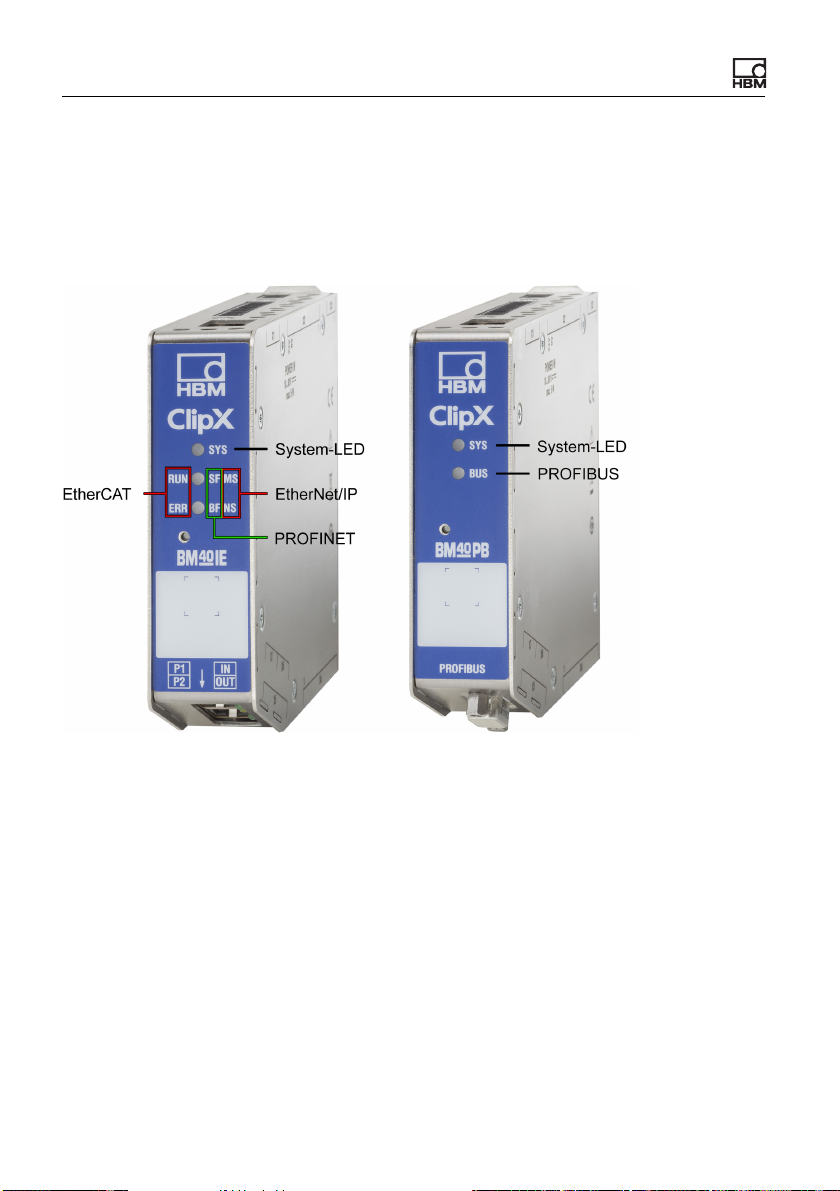
There are 1 to 3 LEDs on the front, depending on the device type. On the
BM40IE the LEDs have different meanings, indicated by differing labels,
depending on the fieldbus.
Fig. 9: Assignment of the LEDs to the interfaces on the BM40IE and BM40PB.
The BM40 only has the system LED.
The following tables list the states indicated by the LEDs. The LEDs flash about
once a second in flash mode, and about five times a second in rapid-flash
mode.
26 A04643_04_X00_00 HBM: public ClipX
Page 29
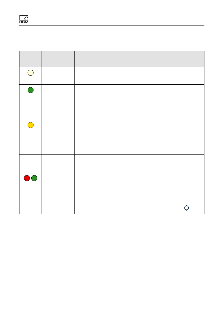
System LED (SYS)
SYS-
LED
Status Meaning
Electrical connections, LEDs
Off
Green
Yellow
/
Red
green
Off
On
On
Flashing
No supply voltage, or ClipX defective.
The ClipX has fully booted up, and is ready.
Error on ClipX bus:
– One or more of the expected devices is not transmitting,
or not responding
– Errors in data transfer
If an invalid external measurement value is correctly trans-
mitted, it does NOT result in a yellow or red system LED. It
causes an invalid status of the external measurement value
in question (one bit per value).
Manual device detection (via the browser) has been started.
or
The ClipX is not ready.
or
None of the other meanings in this table applies. If this state
lasts longer than a few seconds, please contact HBM
nical support” on page 217
.
“Tech-
Note that the red/green flash can also be triggered via your
browser to identify a device (Home menu, click on ).
ClipX A04643_04_X00_00 HBM: public 27
Page 30
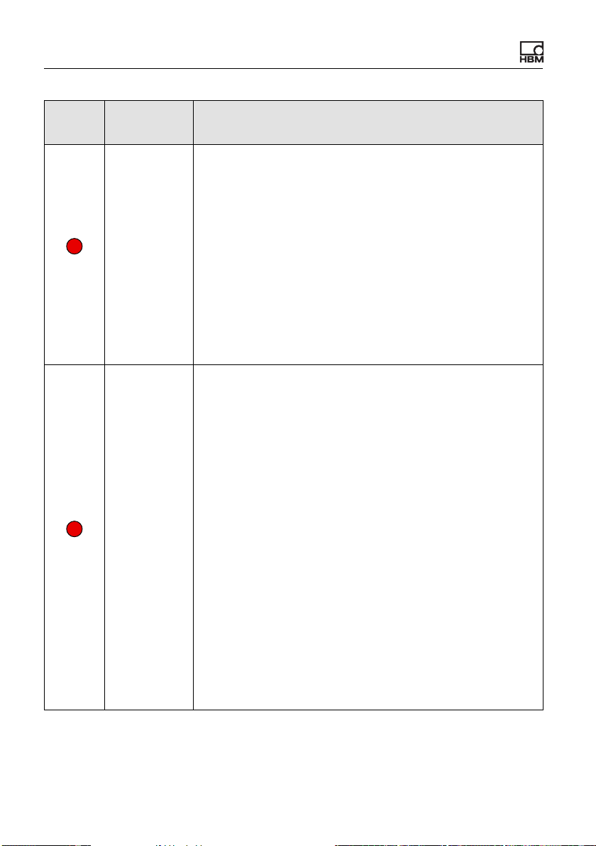
Electrical connections, LEDs
SYS-
LED
Red
Red
Status Meaning
The self-test has failed. This may be due to the following
causes:
– Error in the internal file system
– Error in the A/D converter
– Bridge excitation voltage short-circuit
Flashing rap-
idly
On
– Error in the D/A converter
– Error in communication with a 1-wire TEDS
– Error in the RAM of the ClipX (not in the RAM of the
– Working standard calibration invalid
– Error in communication with the fieldbus hardware in the
One of the status bits is set. This may be due to the following causes:
The ClipX is booting up (initializing everything).
The parameter set is changed or contains errors.
The device is configured as a sync slave but there is no
sync input signal.
The analog output is configured as a current output but not
connected (current loop not closed).
There is a TEDS error.
One or more of the following measured values is invalid:
– Output value of the A/D converter
– Field value (electrical value)
– Gross process value
– Net process value
– Analog output (e.g. overflow)
CPU)
ClipX
or
or
or
or
or
28 A04643_04_X00_00 HBM: public ClipX
Page 31
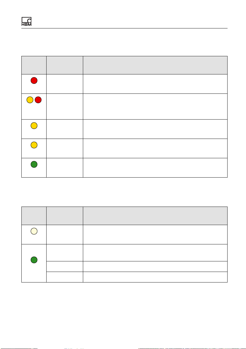
LED state during a firmware update
SYS
LED
Status Meaning
Electrical connections, LEDs
The ClipX is booting up (initializing everything).
The ClipX checks the file integrity, copies or expands files.
Red
/
Yel-
On or flash-
ing
Flashing
low/red
The ClipX clears the CPU flash memory.
The ClipX stores the new program in the CPU flash.
The ClipX checks the CPU flash memory.
Yellow
Yellow
Green
On
Flashing
Flashing
EtherCAT LEDs (RUN, ERR, only BM40IE)
RUN
LED
Off
Status Meaning
Off The ClipX is in the INIT state.
Flashing at
The ClipX is in the PRE-OPERATIONAL state.
2.5 Hz
Green
Single flash The ClipX is in the SAFE-OPERATIONAL state.
On The ClipX is in the OPERATIONAL state.
ClipX A04643_04_X00_00 HBM: public 29
Page 32
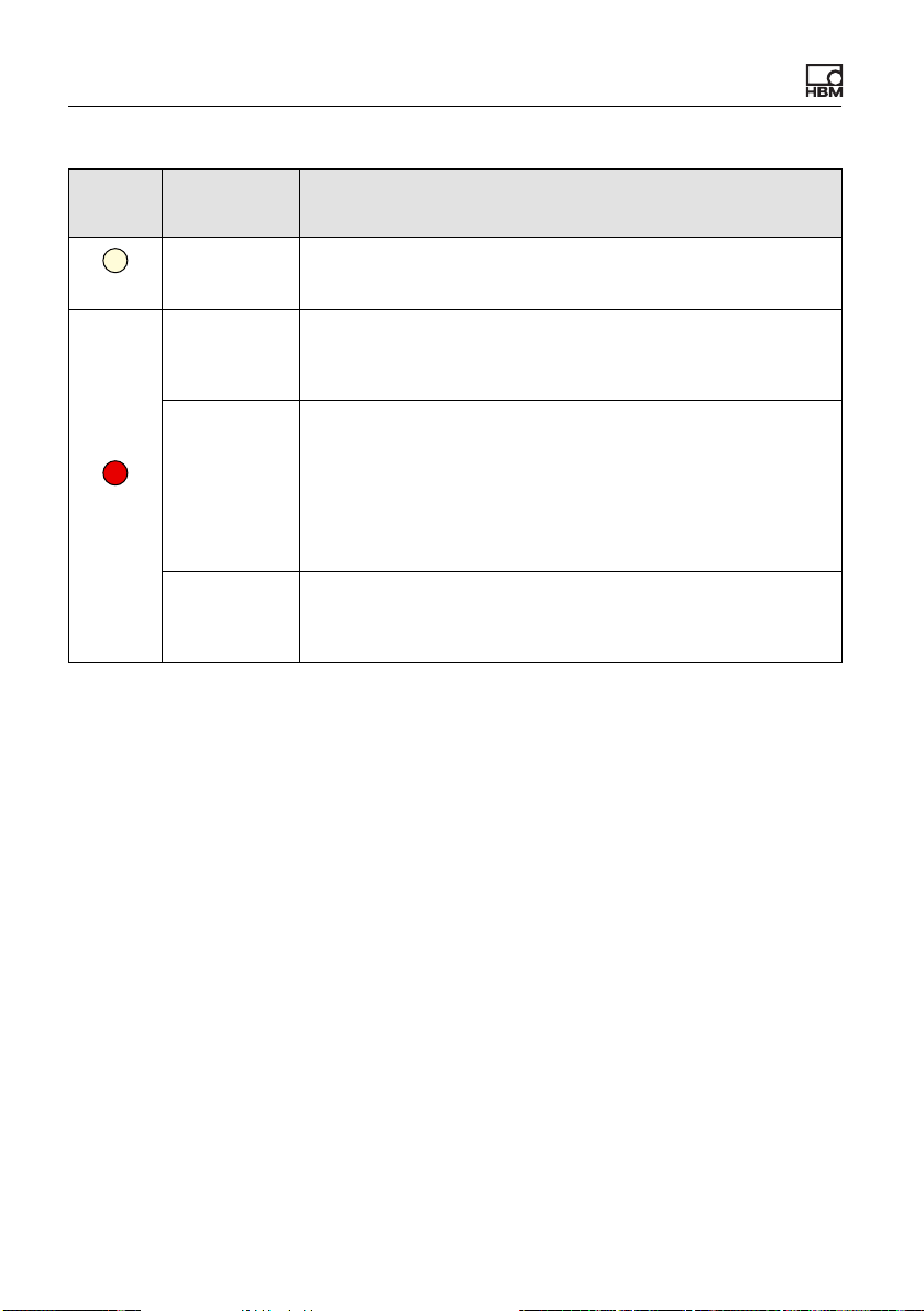
Electrical connections, LEDs
ERR
LED
Off
Status Meaning
Off No error.
The EtherCAT communication is running and error-free.
Flashing
(2.5 Hz)
Invalid configuration.
Possible cause: A change specified by the master is not
possible.
Single flash Local error: The ClipX has autonomously changed the Eth-
erCAT status.
Possible causes:
Red
– A host watchdog timeout has occurred,
– synchronization error. In this case the device switches
automatically to the SAFE-OPERATIONAL state.
Double flash A process data watchdog timeout has occurred.
Possible cause: A synchronization timeout (Sync Manager
watchdog).
30 A04643_04_X00_00 HBM: public ClipX
Page 33
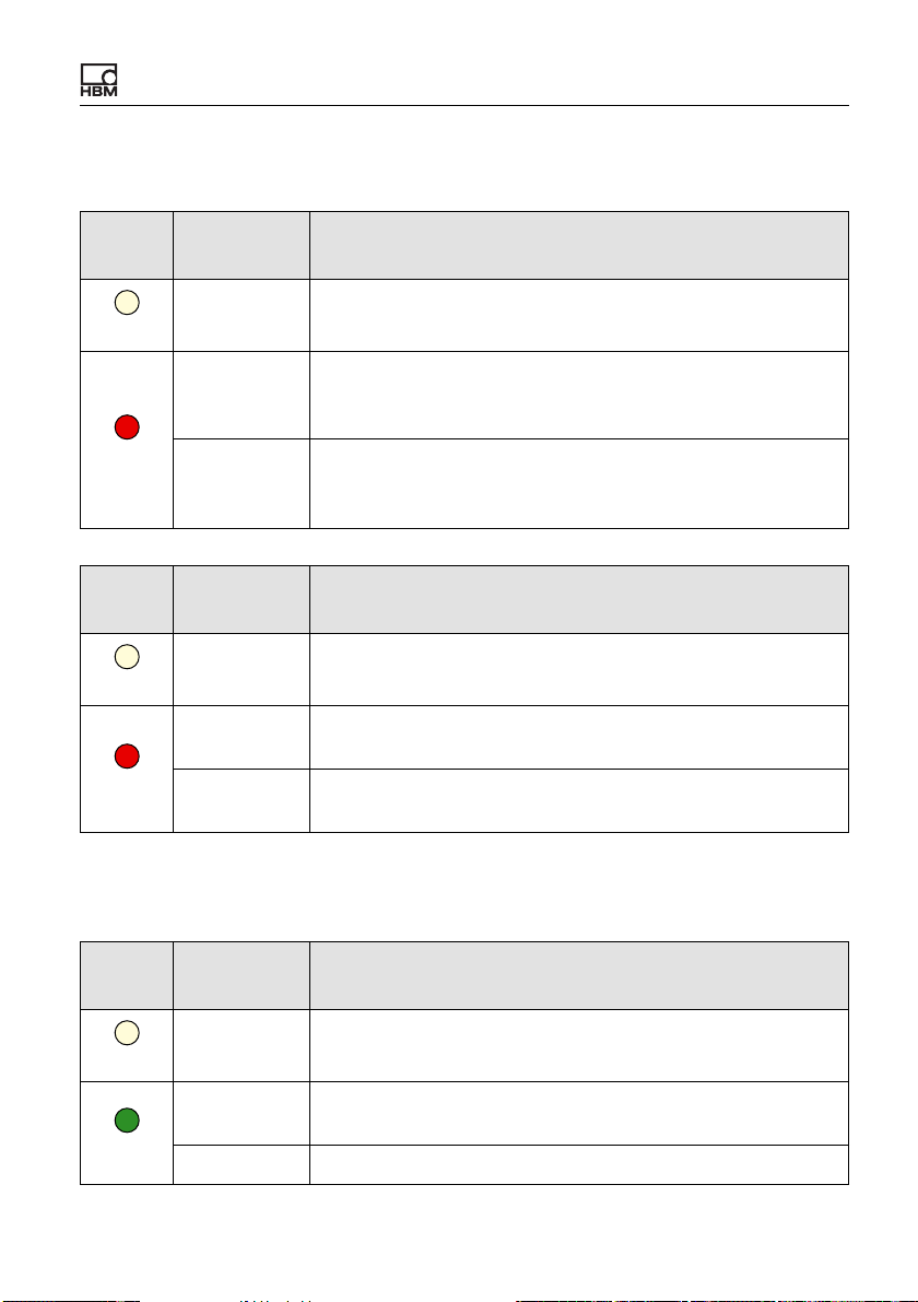
PROFINET LEDs (SF, BF, only BM40IE)
SF
LED
Off
Status Meaning (system error LED)
Off No error.
Electrical connections, LEDs
Flashing
A DCP signal service is triggered over the bus.
(1 Hz, 3 sec-
onds)
Red
On Watchdog timeout.
There is a system error, or a channel, generic or extended
diagnosis.
BF
LED
Status Meaning (bus error LED)
Off No error.
Off
Flashing
No data exchange.
(2 Hz)
Red
On Error: No configuration, slow physical connection or no con-
nection.
EtherNet/IP™ LEDs (MS, NS, only BM40IE)
MS
LED
Status Meaning
Off The ClipX is not on.
Off
Flashing
Standby: The ClipX has not been configured.
(1 Hz)
Green
On The ClipX is running and error-free.
ClipX A04643_04_X00_00 HBM: public 31
Page 34
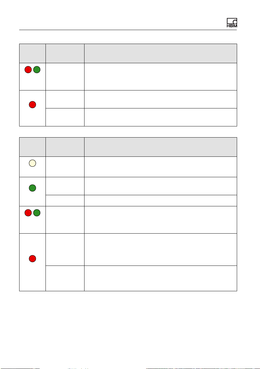
Electrical connections, LEDs
MS
LED
/
Red/
green
Red
NS
LED
Off
Green
/
Red
green
Status Meaning
Flashing
(1 Hz)
Flashing
(1 Hz)
On Serious error: There is an irreparable error. Please contact
The ClipX is running a self-test.
Simple error: The ClipX has detected a reparable error, e.g.
an incorrect configuration.
HBM
“Technical support” on page 217.
Status Meaning
Off The ClipX is not on, or has no IP address.
Flashing
(1 Hz)
On The ClipX is connected to a network device, e.g. a switch.
Flashing
(1 Hz)
No network connection. But the ClipX has been assigned
an IP address.
The ClipX is running a self-test.
Flashing
(1 Hz)
Connection timeout.
One or more connections to this ClipX are in timeout. This
status will only be terminated when all connections have
been restored or you reset the ClipX.
Red
On Duplicate IP address.
The ClipX has detected that the IP address assigned to it
(and set) is already being used in the network.
32 A04643_04_X00_00 HBM: public ClipX
Page 35
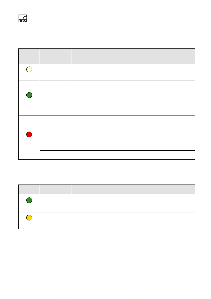
PROFIBUS LED (BUS, only BM40PB)
LED
BUS
Off
Status Meaning
Off The ClipX is not on, or the network has no power.
Electrical connections, LEDs
Flashing
The master is in the CLEAR state.
cyclically
(2 Hz)
Green
On The ClipX is in the RUN state; cyclic communication is run-
ning.
Flashing
The ClipX is not configured.
briefly (1 Hz)
Red
Flashing
cyclically
(2 Hz)
The ClipX is in the STOP state.
No communication; a connection error has possibly
occurred.
On Incorrect PROFIBUS-DP configuration.
LEDs on the Ethernet port
LED Status Meaning
Off No connection.
Green
Yellow
On Connected to a client (PC) or switch.
Flickering Data is being transferred.
ClipX A04643_04_X00_00 HBM: public 33
Page 36
Electrical connections, LEDs
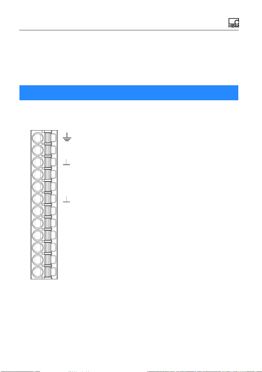
6.5 Connecting the supply voltage
Connect the supply voltage from 10 to 30 VDC to terminal X2 (top).
See also “Available connections and LEDs” on page 24.
Note
Voltages above 30 VDC can destroy the ClipX.
Make sure that the supply voltage is between 10 and 30 VDC.
Housing
ClipX bus
CxA
X
ClipX bus GND
ClipX bus
CxB
Sync
Synchronization
DI
Digital In GND
Digital In 2
DI2
Digital In 1
DI1
Digital Out 2
DO2
Digital Out 1
DO1
Supply 0 V
Plug terminal X2, supply, DIO, Sync, ClipX bus
0V
24V
Supply 10 … 30 V
Fig. 10: Supply voltage at plug terminal X2
For each ClipX you must provide a power output of 5 W plus the power required
for analog and digital outputs. Use an appropriately dimensioned cable for the
supply voltage to avoid an excessive voltage drop when operating multiple
devices. We recommend using wire end ferrules and a cable cross-section of
1.5 mm2 (AWG16).
34 A04643_04_X00_00 HBM: public ClipX
Page 37
Electrical connections, LEDs
6.6 Connecting transducers
Important: Refer to the information on the terminals (“Available con-
nections and LEDs” on page 24) and on cable shielding (“Shielding
and grounding design” on page 23).
The signals of the connected sensor or signal are digitized by the ClipX at
19.2 kHz. You can view various signal processing data values in your browser:
• the field value, i.e. the input signal,
• the ADC value, i.e. the signal of the A/D converter in digits,
• the filtered ADC value, i.e. the signal of the A/D converter based on your
selected filter, also in digits,
• the gross signal, i.e. the signal after zero balancing and scaling,
• the net signal, i.e. the signal after taring.
The taring stage is located in the signal path after the gross signal, and only
effects the net signal. You can use the tare function, for example, to record the
content and total weight of a container or hide the initial load for a force measurement.
With Invalid Signal Value you can specify in your browser which value you
want to display and output if the signal is "invalid" (Amplifier menu). For test
purposes, you can also define and output a Test Signal Value via your browser.
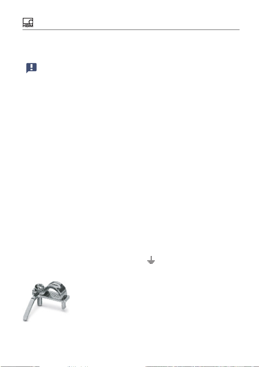
If you want strain relief for the sensor cable, you can use the included shield
connection clamp ME-SAS MINI - 2200456 from PHOENIX. Insert the rigid pin
into the connection for the outer cable shield ( ). Then attach your cable by
the clamp. You can order more clamps from HBM by quoting 1-CON-A1023.
Fig. 11: Shield connection clamp for cable strain relief
ClipX A04643_04_X00_00 HBM: public 35
Page 38
Electrical connections, LEDs
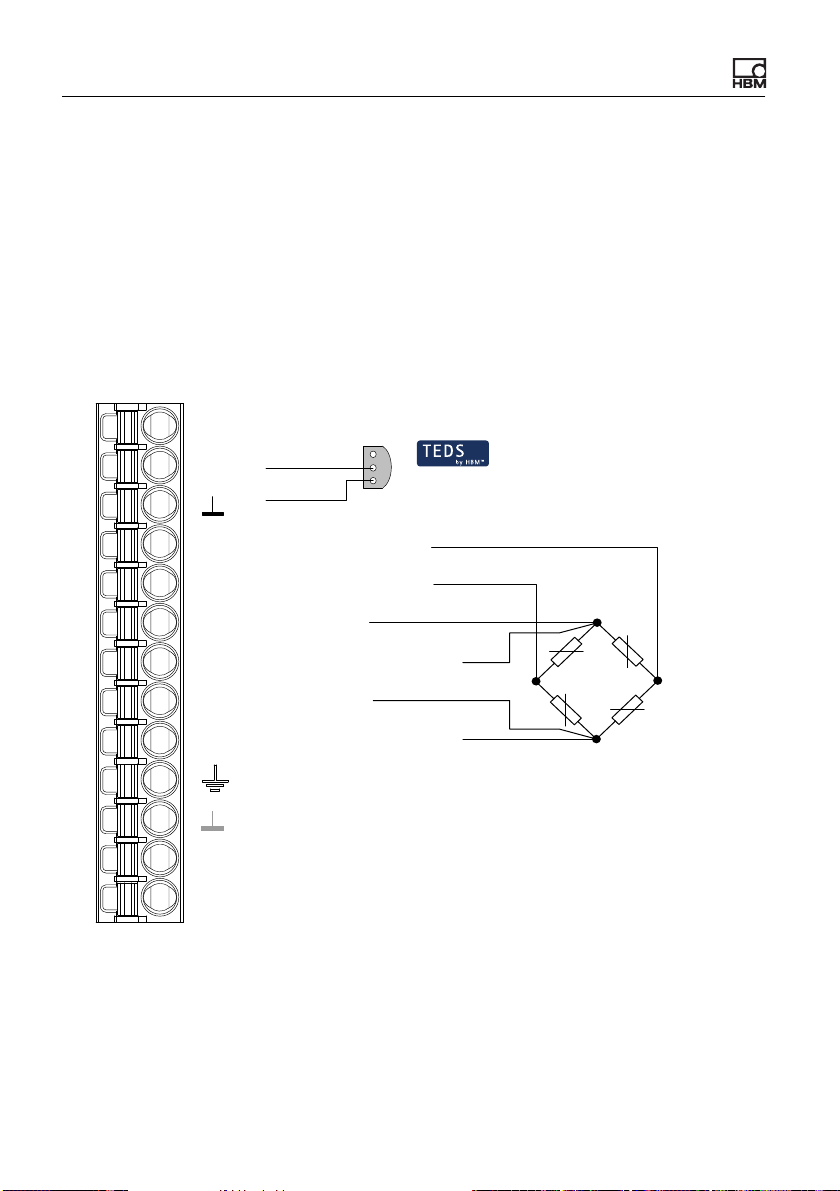
6.6.1 Strain gage full and half bridge, voltage-fed piezo-resistive sensors
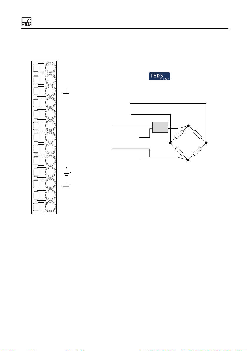
When connecting transducers in a 6-wire configuration, you can also use zerowire TEDS instead of the 1-wire TEDS connection. In this case the TEDS module is looped into the sense lines.
See also “Available connections and LEDs” on page 24, “Shielding and ground-
ing design” on page 23.
Strain gage full bridge, voltage-fed piezo-resistive sensors in 6-wire configuration (1-wire TEDS)
Pt100
TEDS
S
Inner cable shield
4
1
2'
2
3'
3
Plug terminal X4, transducer connection
I
U
Measurement signal -
Measurement signal +
Sense lead -
Bridge excitation voltage -
Sense lead +
Bridge excitation voltage +
Outer cable shield
AI
2
1
1-Wire-TEDS
rd
wh
gy
bk
14
gn
bu
Cable wire colors (HBM transducer):
bu = blue; gn = green; gy = gray;
rd = red; bk = black; wh = white;
2
3
Fig. 12: Plug terminal X4, pin assignment in 6-wire configuration; TEDS
optional, view from below (solder side)
36 A04643_04_X00_00 HBM: public ClipX
Page 39
Electrical connections, LEDs
Strain gage full bridge, voltage-fed piezo-resistive sensors in 6-wire configuration (zero-wire TEDS)
Pt100
TEDS
S
Inner cable shield
4
1
2'
2
3'
3
Plug terminal X4, transducer connection
I
U
Measurement signal -
Measurement signal +
Sense lead -
Bridge excitation voltage -
Sense lead +
Bridge excitation voltage +
Outer cable shield
AI
Zero-Wire-TEDS
rd
wh
gy
TEDS
bk
gn
bu
Cable wire colors (HBM transducer):
bu = blue; gn = green; gy = gray;
rd = red; bk = black; wh = white;
14
Fig. 13: Plug terminal X4, 6-wire pin assignment; TEDS optional
2
3
ClipX A04643_04_X00_00 HBM: public 37
Page 40
Electrical connections, LEDs
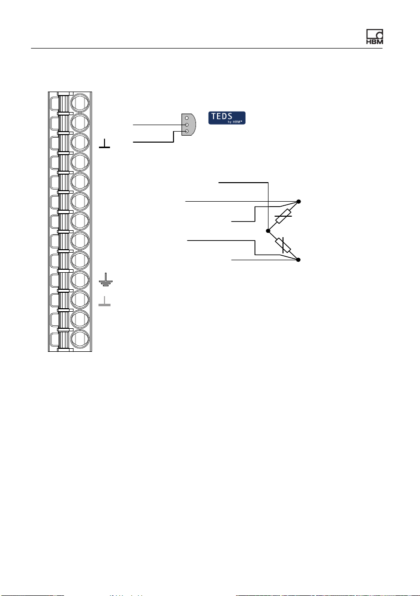
Strain gage half bridge in 6-wire configuration (1-wire TEDS)
Pt100
TEDS
S
Inner cable shield
4 Measurement signal -
1
2'
2
3'
3
Plug terminal X4, transducer connection
I
U
Measurement signal +
Sense lead -
Bridge excitation voltage -
Sense lead +
Bridge excitation voltage +
Outer cable shield
AI
2
1
Cable wire colors (HBM transducer):
bu = blue; gn = green; gy = gray;
bk = black; wh = white;
1-Wire-TEDS
wh
gy
bk
gn
bu
1
2
3
Fig. 14: Plug terminal X4, pin assignment in 6-wire configuration; TEDS
optional, view from below (solder side)
38 A04643_04_X00_00 HBM: public ClipX
Page 41
Electrical connections, LEDs
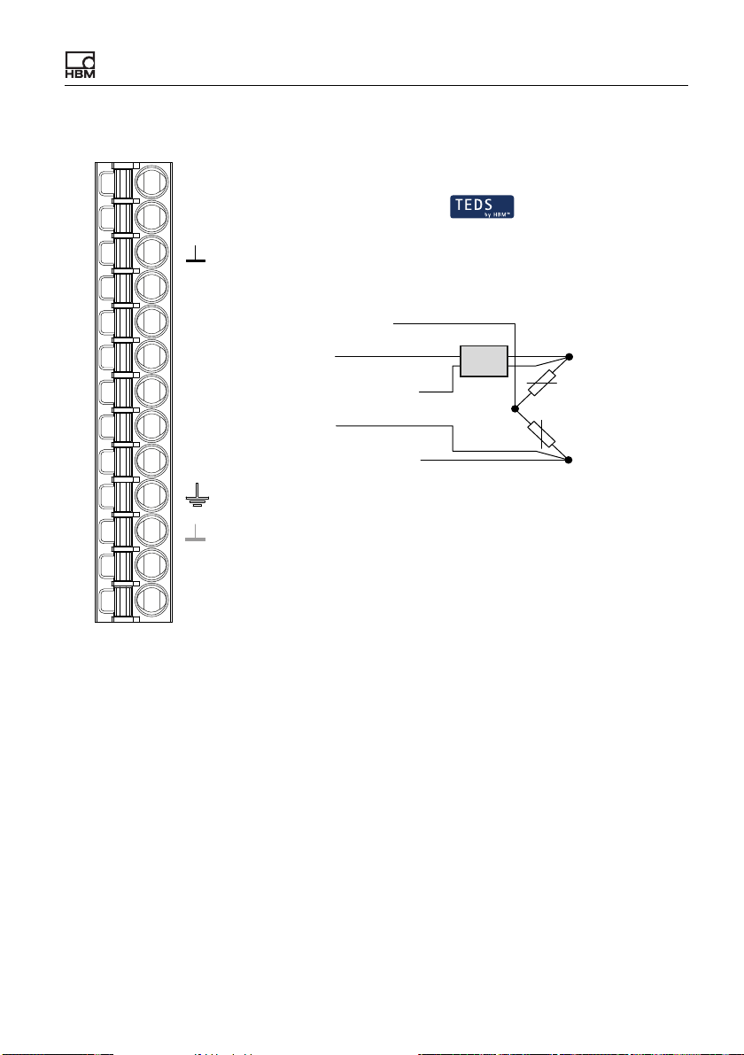
Strain gage half bridge in 6-wire configuration (zero-wire TEDS)
Pt100
TEDS
S
Inner cable shield
4 Measurement signal -
1
2'
2
3'
3
Plug terminal X4, transducer connection
Measurement signal +
Sense lead -
Bridge excitation voltage -
Sense lead +
Bridge excitation voltage +
Outer cable shield
AI
Zero-Wire-TEDS
wh
gy
TEDS
bk
gn
bu
1
2
3
I
U
Cable wire colors (HBM transducer):
bu = blue; gn = green; gy = gray;
bk = black; wh = white;
Fig. 15: Plug terminal X4, 6-wire pin assignment; TEDS optional
ClipX A04643_04_X00_00 HBM: public 39
Page 42
Electrical connections, LEDs
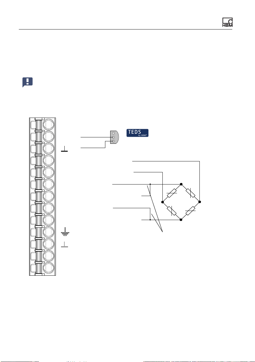
Strain gage full or half bridge in 4-wire configuration
When connecting in a 4-wire configuration, you can only use 1-wire TEDS (as
shown in the diagram).
Important: When connecting in a 4-wire configuration, you must connect the inputs of the sense lines by wire bridges (2 at 2' and 3 at 3',
also referred to as jumpers or feedback bridges) to the supply voltage
outputs, otherwise the measurement value will always be invalid.
Pt100
TEDS
S
4
1
2'
2
3'
3
Plug terminal X4, transducer connection
I
U
Measurement signal -
Measurement signal +
Sense lead -
Bridge excitation voltage -
Sense lead +
Bridge excitation voltage +
Cable shield
AI
2
1
1-Wire-TEDS
rd
wh
2
bk
14
bu
3
Feedback bridges for 4-wire circuitry
Cable wire colors (HBM transducer):
bk = black; bu = blue; rd = red;
wh = white;
Fig. 16: Plug terminal X4, 4-wire pin assignment; pin 4 is not used for half bridge
circuits; TEDS optional, view from below (solder side)
40 A04643_04_X00_00 HBM: public ClipX
Page 43
Electrical connections, LEDs
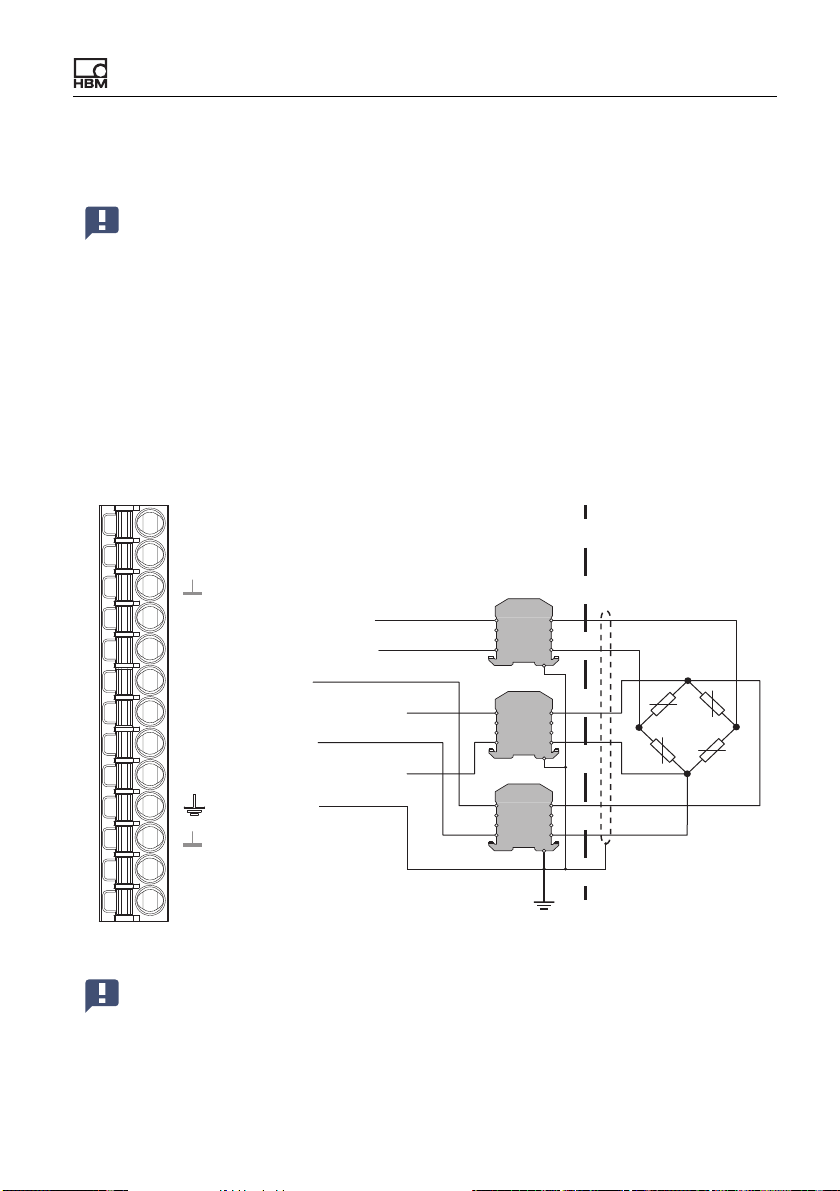
6.6.2 Strain gage full bridge for applications in areas with potentially explosive atmospheres
You cannot use transducers with TEDS when using Zener barriers.
Use cable KAB 7.5/00-2/2/2 and safety barriers 1-SD01A from HBM to connect
transducers in areas with potentially explosive atmospheres to the ClipX (measuring circuit type Ex II (1) GD, [EEx ia] IIC). The connection resistance of the
sensor (or of multiple parallel configured sensors) must be between 80 and
5000 Ohms. The maximum line length is 100 m.
See also “Available connections and LEDs” on page 24.
Strain gage full bridge in 6-wire configuration
Pt100
Pt100
TEDS
S
4
1
2'
2
3'
3
AI
Plug terminal X4, transducer connection
I
U
HBM cable KAB7.5/00-2/2/2
Cable wire colors:
bu = blue; gn = green; gy = gray;
rd = red; bk = black; wh = white;
Measurement signal -
Measurement signal +
Sense lead -
Bridge excitation voltage -
Sense lead +
Bridge excitation voltage +
Cable shields
Potential equalization
rd
wh
gy
bk
gn
bu
Safe
area
851
Z961H
851
Z961
851
Z961H
Explosion hazard
area
4
2
4
14
3
4
Fig. 17: Plug terminal X4, 6-wire pin assignment
Important: Note that transducers between 350 and 5000 Ohms may
only be operated with DC bridge excitation voltage. Also read the
safety instructions for the Zener barrier SD01A in the operating manual.
ClipX A04643_04_X00_00 HBM: public 41
Page 44
Electrical connections, LEDs
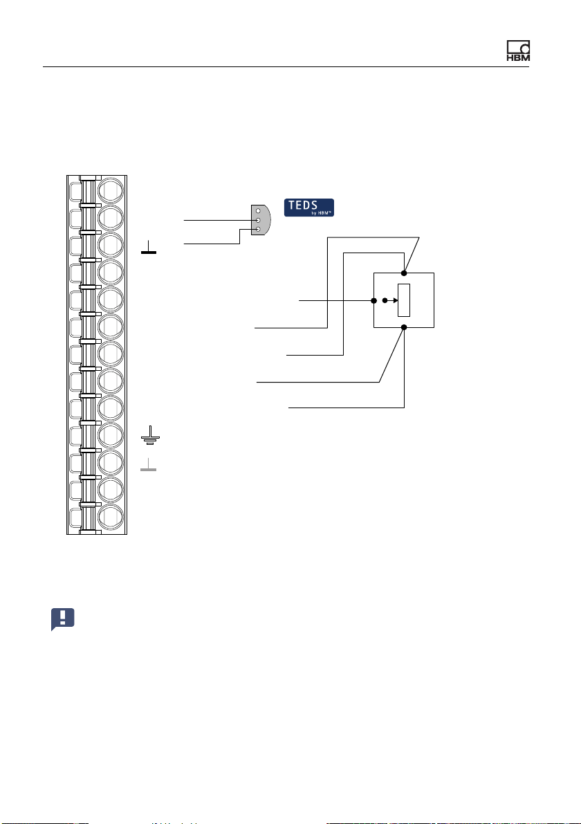
6.6.3 Potentiometric transducer
See also “Available connections and LEDs” on page 24, “Shielding and ground-
ing design” on page 23.
Pt100
TEDS
S
Inner cable shield
4
1
2'
2
3'
3
Plug terminal X4, transducer connection
I
U
Measurement signal -
Measurement signal +
Sense lead -
Excitation voltage -
Sense lead +
Excitation voltage +
Outer cable shield
AI
2
1
1-Wire-TEDS
2
1
3
Fig. 18: Plug terminal X4, potentiometric transducer pin assignment; TEDS
optional, view from below (solder side)
Important: Connect the sense leads to the corresponding excitation
voltage leads by wire bridges (2 at 2' and 3 at 3', also referred to as
jumpers or feedback bridges) if you are not using a 6-wire configuration (with 5 wires assigned). Otherwise a sensor error will be signaled, and you will not be able to measure (invalid measured value).
42 A04643_04_X00_00 HBM: public ClipX
Page 45
Electrical connections, LEDs
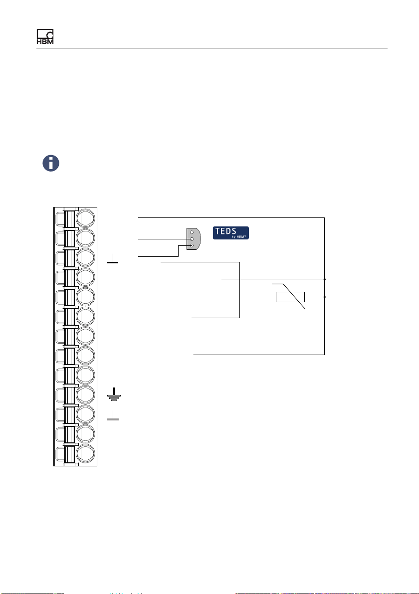
6.6.4 Temperature measurement by Pt100
With the ClipX, temperatures can be measured in degrees Celsius, Kelvin or
Fahrenheit using a Pt100 resistor. The cable resistance is adjusted by way of
the sense line.
See also “Available connections and LEDs” on page 24.
When using TEDS, measurements are initially always in °C. However, you can set a different unit via your web browser's Amplifiers
menu. Any conversion template in the TEDS is not evaluated.
Pt100
TEDS
S
GND
4
1
2'
2
3'
3
Plug terminal X4, transducer connection
I
U
Measurement signal -
Measurement signal +
Sense lead -
Excitation voltage -
Sense lead +
Excitation voltage +
Cable shield
AI
2
1
1-Wire-TEDS
14, 3'
ϑ
Fig. 19: Plug terminal X4, Pt100 pin assignment; TEDS optional, view from
below (solder side)
ClipX A04643_04_X00_00 HBM: public 43
Page 46
Electrical connections, LEDs
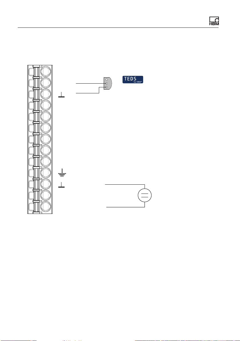
6.6.5 Voltage source (±10 V)
See also “Available connections and LEDs” on page 24.
Pt100
TEDS
S
GND
4
1
2'
2
3'
3
Plug terminal X4, transducer connection
I
U
Measurement signal -
Measurement signal +
Sense lead -
Excitation voltage -
Sense lead +
Excitation voltage +
Cable shield
AI
Analog GND
Current input
Voltage input
2
1
1-Wire-TEDS
U
Fig. 20: Plug terminal X4, electrical voltage source pin assignment; TEDS
optional, view from below (solder side)
44 A04643_04_X00_00 HBM: public ClipX
Page 47
Electrical connections, LEDs
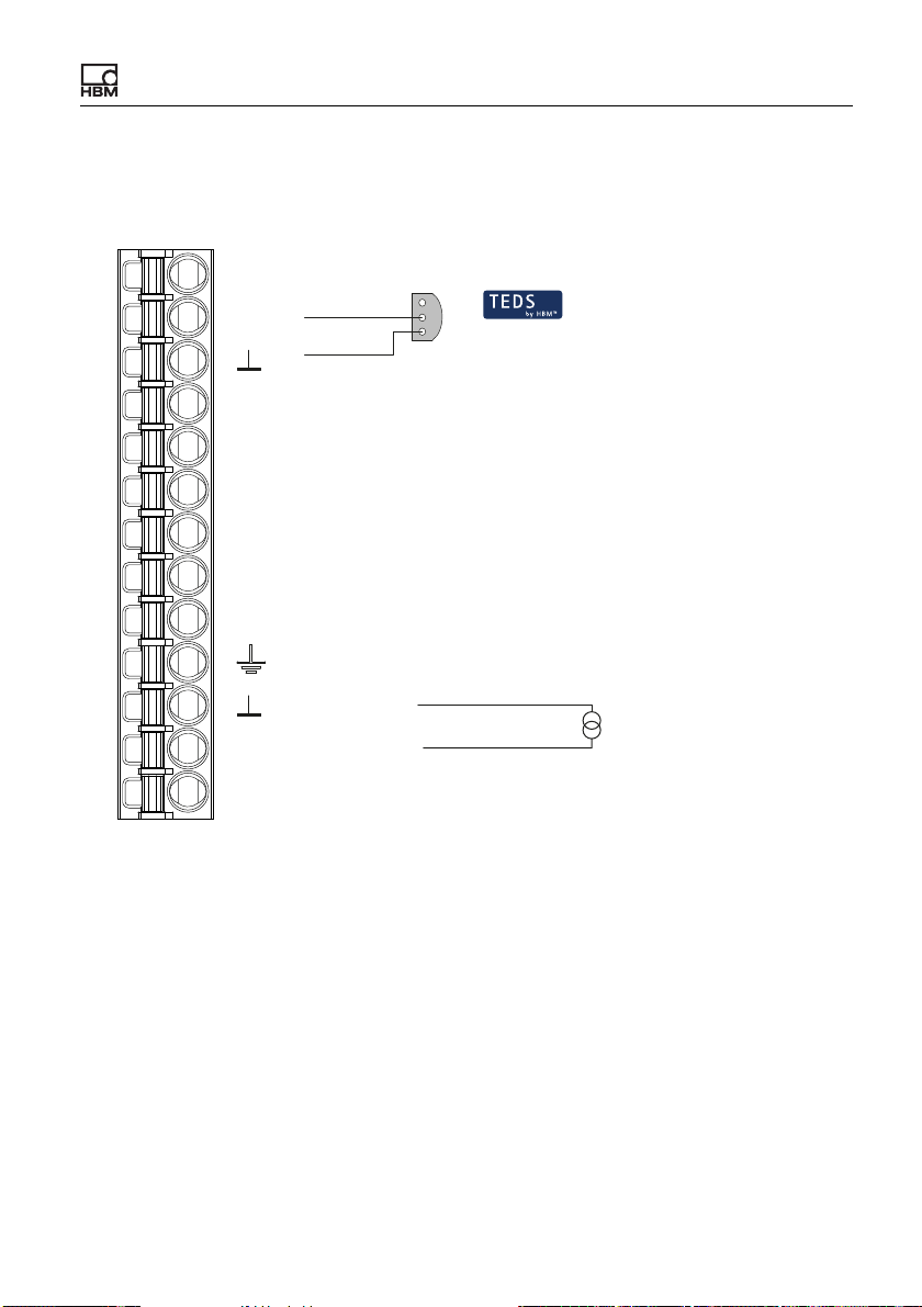
6.6.6 Current source (±20 mA or 4 … 20 mA)
See also “Available connections and LEDs” on page 24.
Pt100
TEDS
S
GND
2
1
1-Wire-TEDS
4
1
2'
2
3'
3
Plug terminal X4, transducer connection
I
U
Measurement signal -
Measurement signal +
Sense lead -
Excitation voltage -
Sense lead +
Excitation voltage +
Cable shield
AI
Analog GND
Current input
Voltage input
I
Fig. 21: Plug terminal X4, current source pin assignment; TEDS optional, view
from below (solder side)
ClipX A04643_04_X00_00 HBM: public 45
Page 48

Electrical connections, LEDs
6.6.7 Current drain (4 … 20 mA)
See also “Available connections and LEDs” on page 24.
Digital In 2
DI2
Digital In 1
DI1
Digital Out 2
DO2
Digital Out 1
DO1
Supply 0 V
Plug terminal X2
0V
Supply 10 … 30 V
24V
Pt100
TEDS
S
GND
4
Measurement signal -
1
Measurement signal +
2'
Sense lead -
2
Excitation voltage -
3'
Sense lead +
3
Excitation voltage +
2
1
1-Wire-TEDS
Sensor
Cable shield
AI
I
U
Analog GND
Current input
Voltage input
Plug terminal X4, transducer connection
Fig. 22: Plug terminals X2 and X4, current drain pin assignment; TEDS optional,
view from below (solder side)
46 A04643_04_X00_00 HBM: public ClipX
Page 49

Electrical connections, LEDs
6.7 Use TEDS
When the ClipX is powered up, or a sensor is connected, the information in the
TEDS module is read and the ClipX is set accordingly (sensor type, scaling,
bridge excitation voltage, etc.).
You can use transducers with both 1-wire and zero-wire TEDS (TEDS module in
the sense lines). If both TEDS connection variants are installed in the transducer, only the 1-wire module is used.
Specifying usage
You can choose between three TEDS usage variants via your browser's TEDS
menu:
1. Ignore TEDS.
2. Use TEDS, if installed.
3. TEDS required.
In the third variant, an error is signaled if no TEDS is found, or cannot be set as
specified.
Supported templates (Information)
• Strain gage (template: Strain Gage)
• Full or half bridge sensor (template: Bridge Sensor)
• Voltage (setting Volt, template: High Level Voltage Output Sensor)
• Sensor with current output (settings Current, template: Current Loop Output
Sensor)
• Potentiometer (template: Potentiometric Voltage Divider)
• Pt100 (template: Resistive Temperature Detector)
• Two-point scaling (always included in the respective sensor template)
• Polynomial scaling (template: Calibration Curve)
• HBM Channel Name (max. 45 ASCII characters)
• HBM Unit Conversion (1 conversion factor and new unit)
• HBM User Defined ID (max. 15 ASCII characters, e.g. for an identifier)
ClipX A04643_04_X00_00 HBM: public 47
Page 50

Electrical connections, LEDs
Restrictions
• Only 1 segment with a maximum 4th order is supported for polynomial scal-
ing (Calibration Curve). Only “Electrical” is supported as “Domain parameter
of the Calibration Curve”, meaning electrical values are converted to physical values. Correction of physical values to other physical values is not supported.
• For Pt100 (Resistive Temperature Detector) measurements are always in
°C; the HBM Unit Conversion template cannot be used. However, you can
set a different unit via your web browser's Amplifiers menu. Any conversion
template in the TEDS is not evaluated.
48 A04643_04_X00_00 HBM: public ClipX
Page 51
Electrical connections, LEDs
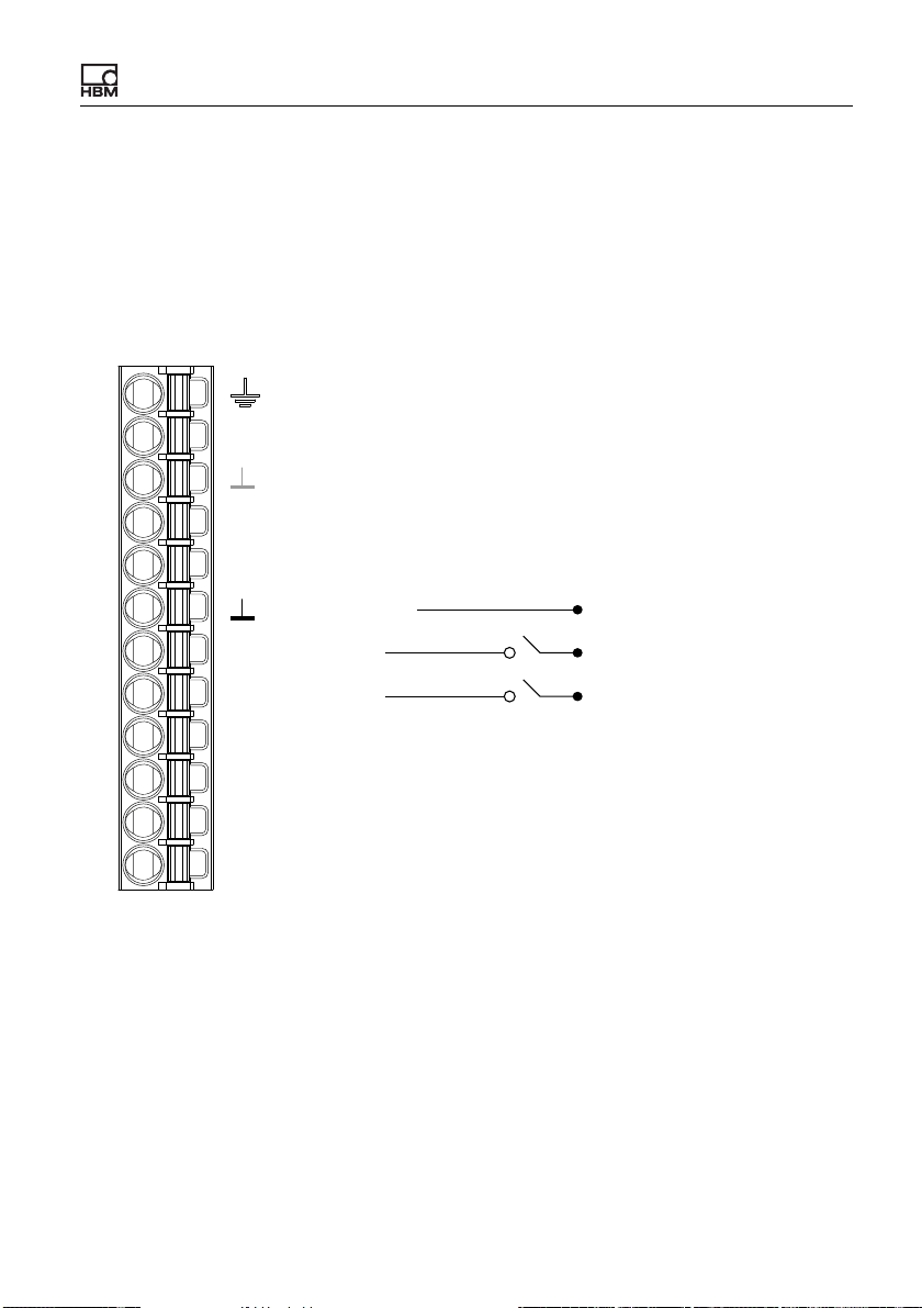
6.8 Connecting the digital inputs and outputs
The digital inputs and the flags or bits for the outputs are analyzed after 1 ms at
the latest in the event of a change.
See also “Available connections and LEDs” on page 24.
Digital inputs
Housing, cable shield optional
ClipX bus
CxA
X
ClipX bus GND
ClipX bus
CxB
Sync Synchronization
DI
DI2
DI1
Digital In GND
Digital In 2
Digital In 1
LOW: 0 V … 5 V
HIGH: 10 V … 30 V
DO2
Digital Out 2
Digital Out 1
DO1
Plug terminal X2, supply, DIO, Sync, ClipX bus
Supply 0 V and Digital Out GND
0V
Supply 10 … 30 V
24V
Fig. 23: Plug terminal X2, pin assignment of digital inputs
The digital inputs must be switched against a positive voltage (≥10 V). An open
input will be detected as Low level (0).
ClipX A04643_04_X00_00 HBM: public 49
Page 52
Electrical connections, LEDs
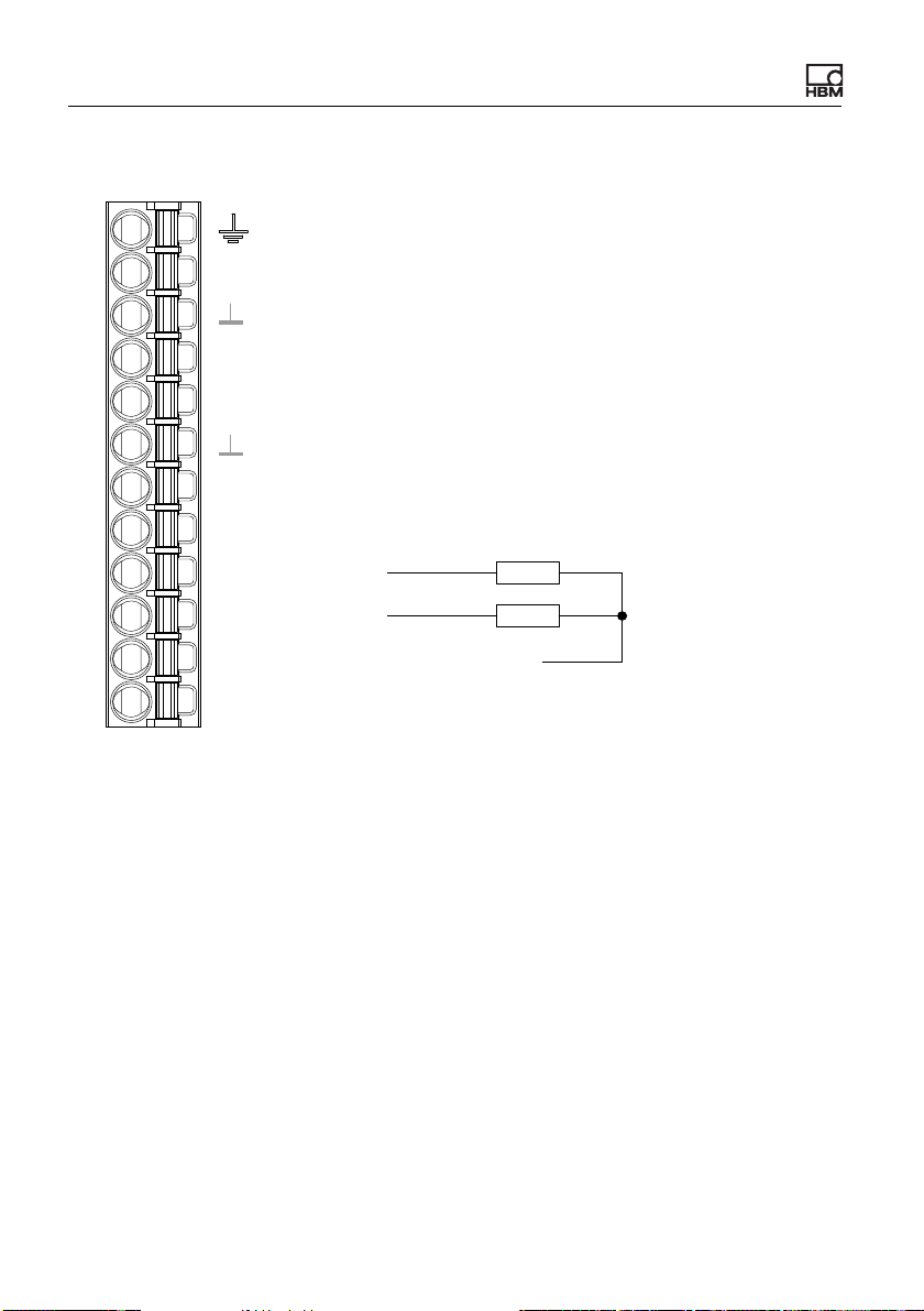
Digital outputs
Housing, cable shield optional
CxA
ClipX bus
X
ClipX bus GND
ClipX bus
CxB
Sync
Synchronization
DI
Digital In GND
DI2
Digital In 2
DI1
Digital In 1
Digital Out 2
DO2
Digital Out 1
Plug terminal X2, supply, DIO, Sync, ClipX bus
DO1
Supply 0 V and Digital Out GND
0V
24V
Supply 10 … 30 V
Fig. 24: Plug terminal X2, pin assignment of digital outputs
Start-up behavior of the digital outputs
On starting up the ClipX (power on), each output initially has a high output resistance. After initializing, the status of the settings is determined in the Start
parameter set. When an output is active, the supply voltage (10 … 30 V) is
switched through to it.
The factory default setting is: Output deactivated.
50 A04643_04_X00_00 HBM: public ClipX
Page 53
Electrical connections, LEDs
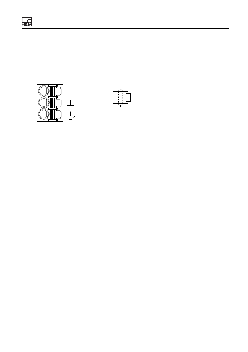
6.9 Connecting the analog output
You can output voltage (±10 V) or current (4 … 20 mA). The analog output is
short-circuit-proof, the bandwidth is 3.8 kHz, the update rate is 19.2 kHz.
See also “Available connections and LEDs” on page 24.
AO
Analog Out +
AO
Analog Out ‒
analog output
Plug terminal X3,
Cable shield
Fig. 25: Plug terminal X3, pin assignment for analog output
Start-up behavior
On starting up the ClipX (power on), the analog output initially has a high output
resistance. After initializing, the status of the settings is determined in the Start
parameter set.
The factory default setting is: Output deactivated, gross signal as input (source),
zero value 0 V, scaling 0/0 and 5/5, value in case of “invalid” signal 0 V and test
signal 0 V (both inactive).
Value in case of error
Which value is outputted depends on whether you activate the value in case of
an “invalid” signal or not. Make the setting via the ClipX web server in your
browser.
1. Value in case of “invalid” signal active (switch in browser on the right and
red)
If the input signal becomes invalid, or the output signal would be outside the
range of ±11 V or less than 3 mA or greater than 21 mA, the specified value
is outputted.
2. Value in case of “invalid” signal not active (switch in browser on the left and
gray)
The highest or lowest possible value is outputted depending on the signal
(±11 V, or 3 mA or 21 mA).
ClipX A04643_04_X00_00 HBM: public 51
Page 54
Electrical connections, LEDs
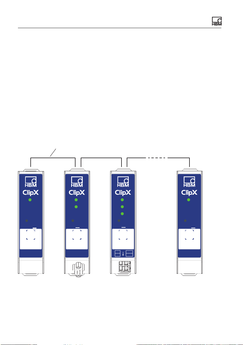
6.10 Using multiple ClipX devices, ClipX bus
You can transfer one measured value with status from each of up to five other
ClipX devices over the ClipX bus to a ClipX and then capture them simultaneously with the values of that device. The connections use line topology. The
maximum cable length between two devices is 30 cm.
Interconnect the CxA terminals and CxB terminals respectively of up to six
devices. Lay the lines from the first device to the second, from the second to the
third device, etc. (line topology). The ClipX bus GND connection is additionally
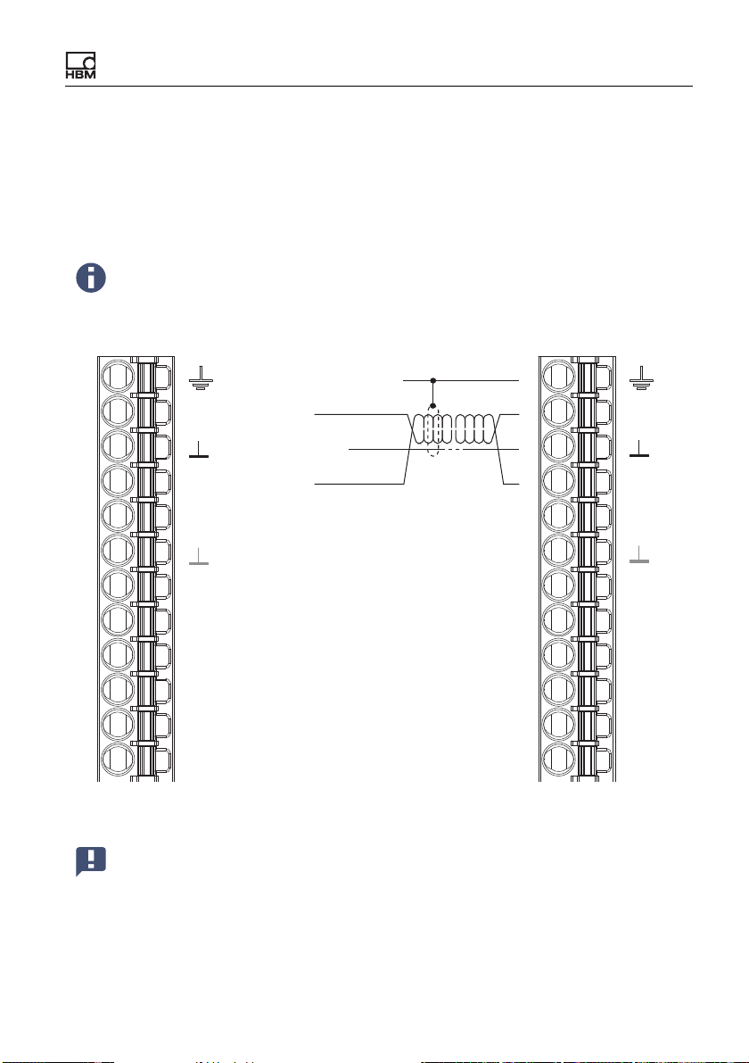
required. The CxA and CxB lines must be twisted and shielded.
See also “Available connections and LEDs” on page 24, “Synchronizing multiple
ClipX CF amplifiers” on page 54.
max. 30 cm
RUN
ERR
BM40IE
P1
P2
SYS
SF MS
BF NS
IN
OUT
BM
SYS
40
BM
SYS
40
SYS
BUS
40
BM
PB
PROFIBUS
Fig. 26: Transferring a measured value from multiple ClipX devices
The ClipX bus synchronizes automatically. All you have to do is enter the High-
est Address (number of devices) and the Own Address (location where the
52 A04643_04_X00_00 HBM: public ClipX
Page 55
Electrical connections, LEDs
own device is to appear) in your browser (ClipX Bus menu). Address 1 serves
as the bus master; all the other addresses are slaves. Specify which signal to
transmit at each device. The status (valid/invalid) is transmitted along with the
measurement signal. 1000 values per second are transmitted per device
(including CRC check).
If you set Own Address for a device to 0, the ClipX bus will be deactivated for that device, meaning no other devices are visible, and no
own signal can be transmitted.
Housing, cable shields
CxA
CxB
Sync
DI2
DI1
DO2
DO1
Plug terminal X2, supply, DIO, Sync, ClipX bus
0V
24V
ClipX bus
X
ClipX bus GND
ClipX bus
Synchronization
DI
Digital In GND
Digital In 2
Digital In 1
Digital Out 2
Digital Out 1
Supply 0 V
Supply 10 … 30 V
Fig. 27: Plug terminal X2, pin assignment for ClipX bus
Important: Termination resistors are not necessary, and must not be
used. The maximum cable length between two devices is 30 cm.
CxA
X
CxB
Sync
DI
DI2
DI1
DO2
DO1
0V
24V
ClipX A04643_04_X00_00 HBM: public 53
Page 56
Electrical connections, LEDs
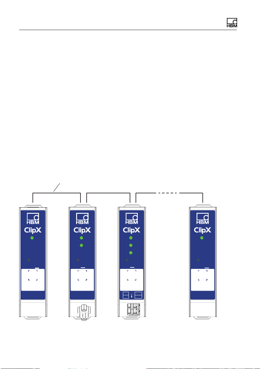
6.11 Synchronizing multiple ClipX CF amplifiers
You should synchronize multiple ClipX devices that supply sensors with carrier
frequency (CF) so that the carrier frequency measuring amplifiers do not interfere with each other. This will prevent crosstalk between adjacent sensor
cables, resulting in disturbance to measurements. If you are using only sensors
with direct voltage (DC) amplifiers, no synchronization is necessary.
To synchronize, interconnect the Sync terminals of the devices and the ClipX
bus GND terminals, unless you have already connected the latter to transmit
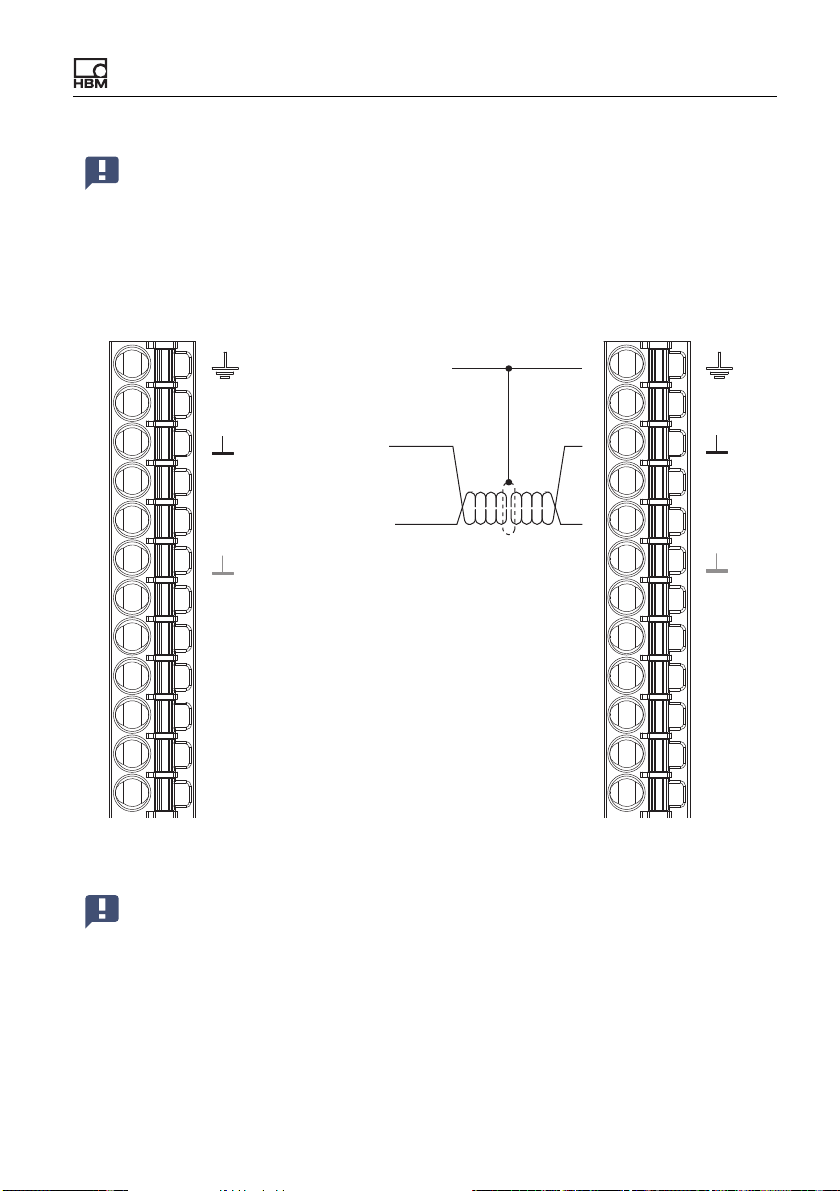
measured values. Lay the lines from the first device to the second, from the second to the third device, etc. (line topology). The cable must have twisted-pair
wires, and be shielded. The ClipX bus GND and Sync lines must be twisted and
shielded.
See also “Available connections and LEDs” on page 24, “Using multiple ClipX
devices, ClipX bus” on page 52.
max. 30 cm
RUN
ERR
BM40IE
P1
P2
SYS
SF MS
BF NS
IN
OUT
BM
SYS
40
BM
SYS
40
SYS
BUS
40
BM
PB
PROFIBUS
Fig. 28: Synchronizing multiple ClipX devices
54 A04643_04_X00_00 HBM: public ClipX
Page 57
Electrical connections, LEDs
Important: On the first device you must enable Sync Mode Master
[Master sync mode]. All the others operate as slaves, so the switch
must not be active. Make the setting in your browser using the Ampli-
fier and Sensor Type menu items. Synchronization is only possible
for sensor types with carrier frequency (CF), not for DC. No synchronization of the time base or the A/D converters takes place.
Housing, cable shields
CxA
CxB
Sync
DI2
DI1
DO2
DO1
Plug terminal X2, supply, DIO, Sync, ClipX bus
0V
24V
ClipX bus
X
ClipX bus GND
ClipX bus
Synchronization
DI
Digital In GND
Digital In 2
Digital In 1
Digital Out 2
Digital Out 1
Supply 0 V
Sipply 10 … 30 V
Fig. 29: Plug terminal X2, pin assignment for Sync signal
Important: Termination resistors are not necessary, and must not be
used. The maximum cable length between two devices is 30 cm.
CxA
X
CxB
Sync
DI
DI2
DI1
DO2
DO1
0V
24V
ClipX A04643_04_X00_00 HBM: public 55
Page 58
Electrical connections, LEDs
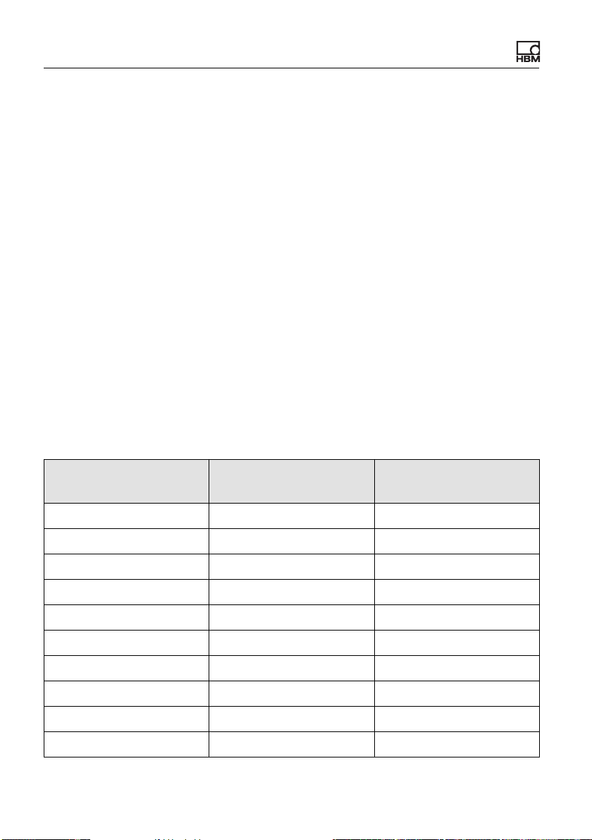
6.12 Signal phase delays within the ClipX and over the ClipX bus
The various modules in the ClipX are combined into a number of groups, each
with fixed cycle times. This makes it easier to calculate the total phase delay of
a signal. The following diagrams indicate the phase delays of the various groups
as well as any potential additions you might need to allow for the hardware of
inputs/outputs. To calculate the maximum phase delay of signals running
through more than one group, such as min/max values obtained from calculated
channels, simply add together the phase delays of the respective groups.
Pay attention to the sequencing of the analysis within a group. If source signals
are formed only later in the group, this will double the phase delay until the
result is available.
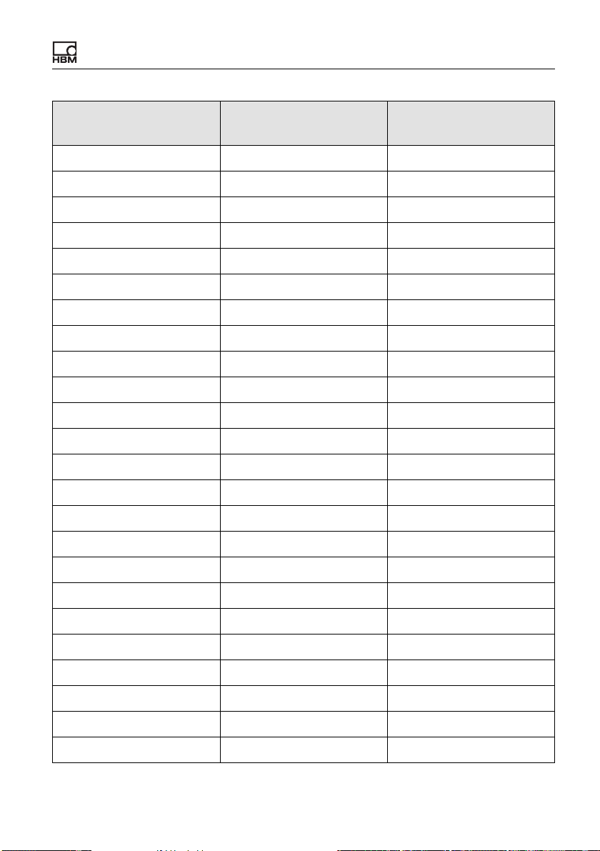
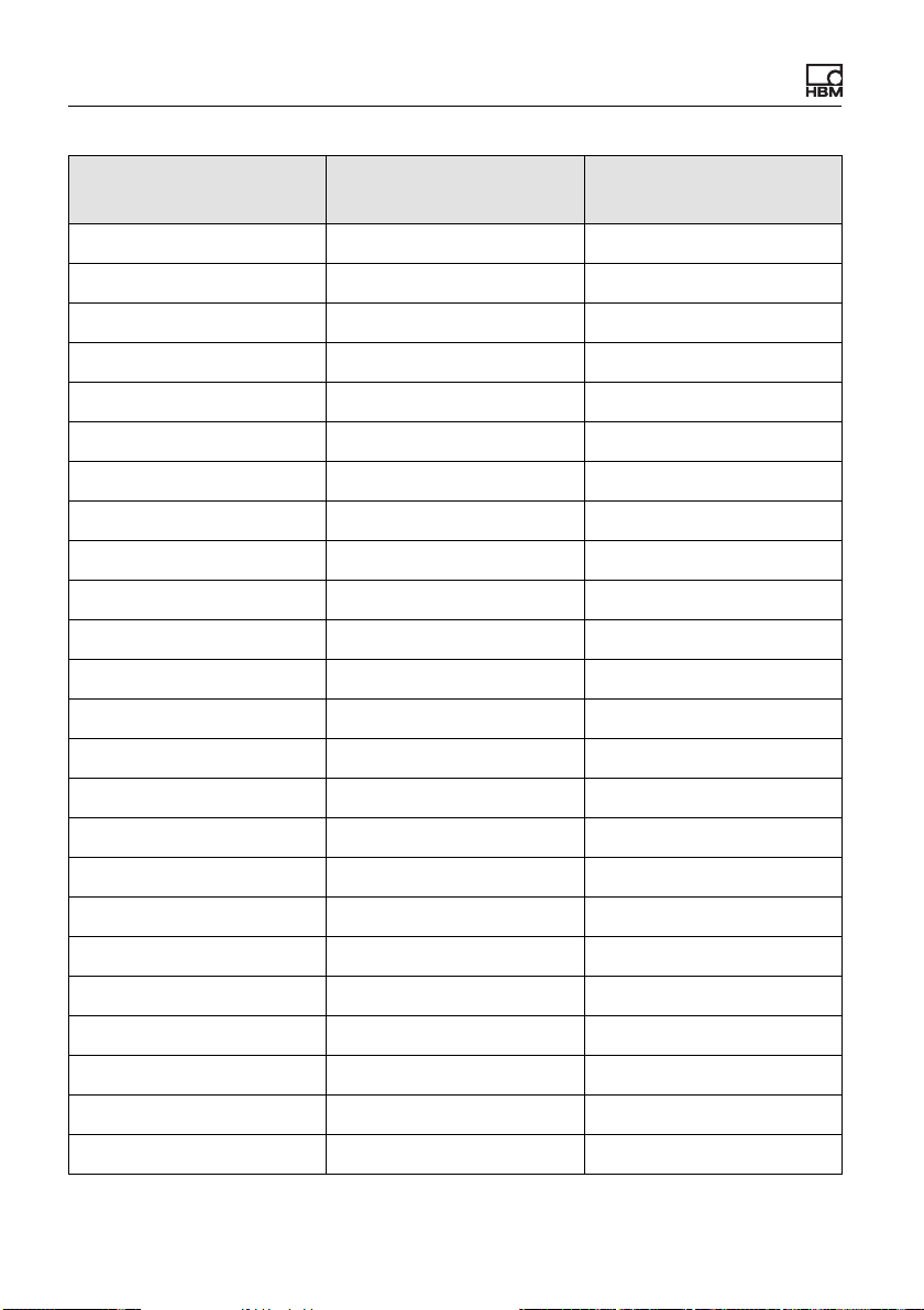
Phase delays of A/D converter plus digital filter
Some filter frequencies are only possible with a DC amplifier, and are identified
accordingly. The bandwidth with DC and the digital filter switched off (Filter
OFF) is 3800 Hz. The filter phase delay is then 0 ms, meaning the phase delay
of the A/D converter with no filter is 260 μs.
Cut-off frequency in HzPhase delay with Bes-
sel filter in ms
Phase delay with But-
terworth filter in ms
3000 (DC only) 0.403 0.480
2500 (DC only) 0.432 0.524
2000 (DC only) 0.475 0.590
1500 (DC only) 0.547 0.700
1000 (DC only) 0.690 0.920
800 (DC only) 0.798 1.085
750 (DC only) 0.833 1.140
600 (DC only) 0.977 1.360
500 (DC only) 1.120 1.580
400 (DC only) 1.335 1.910
56 A04643_04_X00_00 HBM: public ClipX
Page 59
Electrical connections, LEDs
Cut-off frequency in HzPhase delay with Bes-
sel filter in ms
350 (DC only) 1.489 2.146
280 (DC only) 1.796 2.617
250 (DC only) 1.980 2.900
200 2.410 3.560
160 2.948 4.385
150 3.127 4.660
120 3.843 5.760
100 4.560 6.860
80 5.635 8.510
75 5.993 9.060
60 7.427 11.260
50 8.860 13.460
40 11.010 16.760
35 12.546 19.117
30 14.593 22.260
Phase delay with But-
terworth filter in ms
25 17.460 26.660
20 21.760 33.260
16 27.135 41.510
15 28.927 44.260
12 36.093 55.260
10 43.260 66.260
8 54.010 82.760
7.5 57.593 88.260
6 71.927 110.260
ClipX A04643_04_X00_00 HBM: public 57
Page 60
Electrical connections, LEDs
Cut-off frequency in HzPhase delay with Bes-
sel filter in ms
5 86.260 132.260
4 107.76 165.26
3.5 123.12 188.83
3 143.59 220.26
2.5 172.26 264.26
2 215.26 330.26
1.6 269.01 412.76
1.2 358.59 550.26
1 430.26 660.26
0.8 537.76 825.26
0.75 573.59 880.26
0.6 716.93 1100.26
0.5 860.26 1320.26
0.4 1075.26 1650.26
0.35 1228.83 1885.97
Phase delay with But-
terworth filter in ms
0.28 1535.97 2357.40
0.25 1720.26 2640.26
0.2 2150.26 3300.26
0.16 2687.76 4125.26
0.15 2866.93 4400.26
0.1 4300.26 6600.26
0.075 5733.59 8800.26
0.05 8600.26 13200.26
0.035 12286.0 18857.4
58 A04643_04_X00_00 HBM: public ClipX
Page 61
Electrical connections, LEDs
Cut-off frequency in HzPhase delay with Bes-
sel filter in ms
Phase delay with But-
terworth filter in ms
0.025 17200.3 26400.3
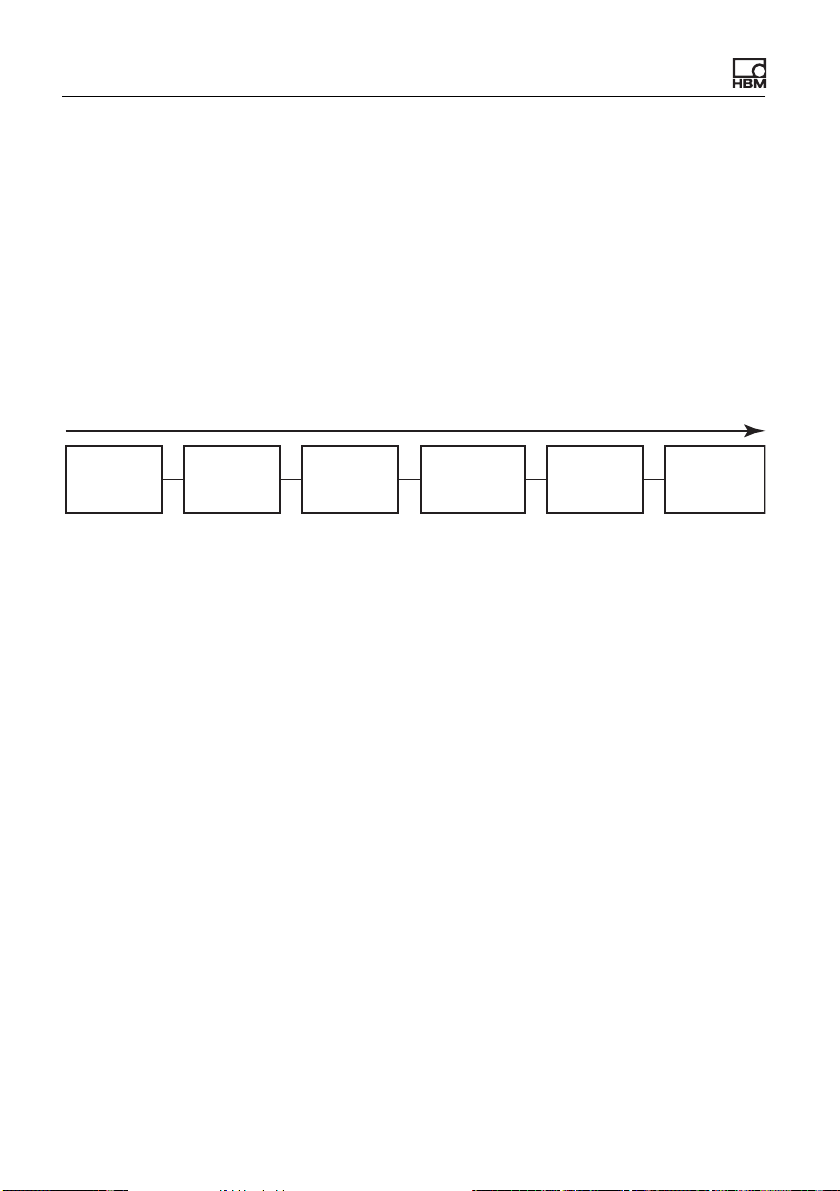
0.02 21500.3 33000.3
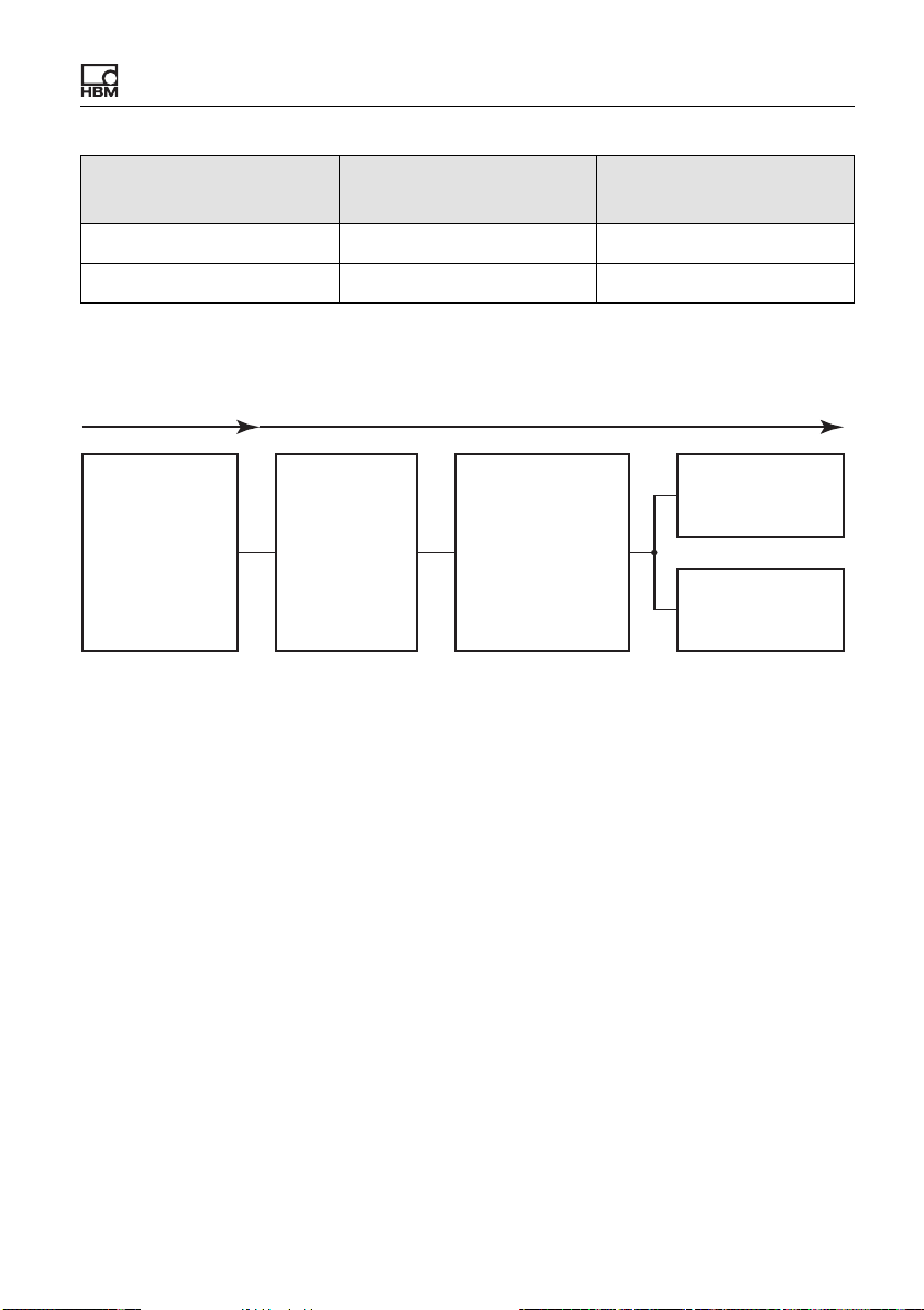
Group 1: Measured values
260 μs
min. 52 μs
ADC unfiltered
ADC filtered
Field value (el. value)
A/D converter
(ADC)
1)
Filter off: 0 s; propagation times filter and A/D converter see table; The result is time for an output
Filter
1)
Gross value
Net value
Minimum
Maximum
2)
2)
Peak-to-peak
2)
Limit value switch
Analog output
2)
3)
signal of 50% of the full scale value with a jump at the input.
2)
These signals can also use other sources. The phase delays of the source signals must then be
added.
3)
If the analog output is to output a value from this group, you must add on 52 μs. If you are using
a source from a different group, you must add the phase delay of the source signal to the 52 μs.
Fig. 30: Minimum phase delay for group 1: 52 μs plus A/D converter conversion
time
Some signals might also have sources from other groups. For example, the
analog output might deliver a signal from the ClipX bus. In these cases,you
must add the phase delay of the source signal's group in order to get the total
phase delay:
ClipX A04643_04_X00_00 HBM: public 59
Page 62
Electrical connections, LEDs
Example 1
Phase delay from input, e.g. 10 V, 20 mA or DC full/half bridge, to analog output
(10 V) with a Bessel filter at 1 kHz:
• A/D converter (ADC) plus filter: 260 μs
• Analog output: 52 μs
Added to this is a jitter of up to 52 μs, as the A/D converter only starts a new
conversion every 52 μs. So the total phase delay is 742 … 797 μs.
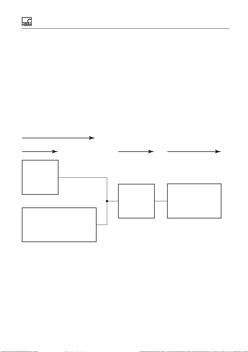
Group 2: Flags, Digital I/Os, calculated values, ClipX bus
1 ms
Flags and
values from
fieldbus
1)
Changes in digital flags are analyzed in the following order: Zeroing, taring, clear zero value,
clear tare value, reset limit value switch, reset peak values, hold held values, clear hold values.
2)
The digital outputs have an additional response time of max. 0.25 ms.
3)
Asynchronous transfer of the values on the ClipX bus is complete after max. 1 ms, i.e on the next
cycle.
Digitale
inputs
Computed
channels
Digital flags
(I/O flags)
1)
Digital
outputs
2)
ClipX bus:
Start
transfer
3)
Fig. 31: Maximum phase delay for group 2: 1 ms
Example 2
Phase delay from input (see group 1) to a digital output with a Bessel filter at
1 kHz, limit switch at half the step height.
• A/D converter (ADC) plus filter: 690 μs
• Group 2: 1 ms
• Digital output: max. 250 μs response time
Added to this is a jitter of up to 52 μs, as the A/D converter is not synchronized
with group 1. In the best case, a value is available at the start of the analysis in
group 2 and can be outputted directly at the digital output for example. So the
total phase delay is 940 … 1992 μs.
60 A04643_04_X00_00 HBM: public ClipX
Page 63
Electrical connections, LEDs
Example 3
Phase delay of a value from the ClipX bus via a limit switch to a digital output.
• ClipX bus: 1 ms
• Limit value switch: 52 μs
• Digital output: 1 ms plus max. 250 μs response time
This results in a total phase delay of 2.3 ms. However, you must add the phase
delay in the device that places the value on the ClipX bus in order to get the time
from the sensor until a response occurs.
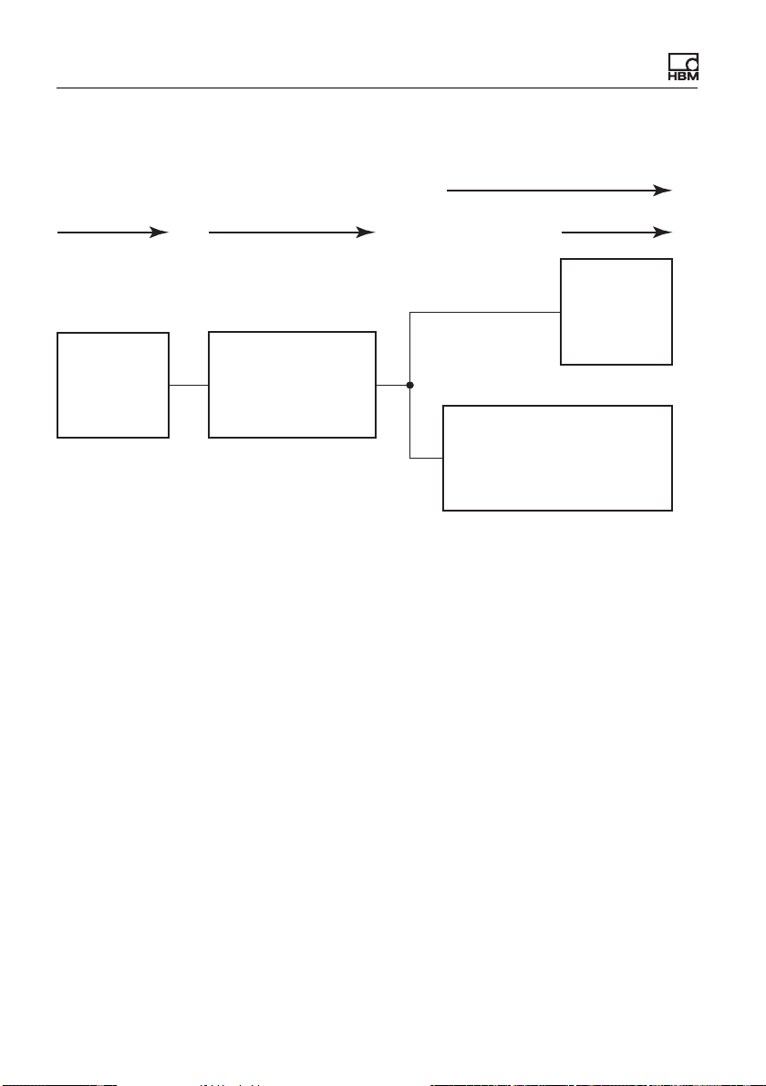
Group 3: Data from fieldbus master to ClipX
1 ms
1)
Polling rate
EtherCAT/
PROFINET
Polling rate
EtherNet/IP /
PROFIBUS
1)
At 4 kHz frame rate.
Fig. 32: Phase delay for group 3
ca. 250 μs250 μs
ClipX
fieldbus
controller
0.25 … 1 ms
Period duration
of frame rate
of fieldbus
ClipX A04643_04_X00_00 HBM: public 61
Page 64
Electrical connections, LEDs
Group 4: Data from ClipX to fieldbus master
approx. 250 μs 0.25 … 1 ms
1 ms
Update rate
EtherCAT/
PROFINET
250 μs
1)
ClipX
fieldbus
controller
1)
At 4 kHz frame rate.
Period duration
of frame rate
of fieldbus
Fig. 33: Phase delay for group 4
Update rate
EtherNet/IP/
PROFIBUS
62 A04643_04_X00_00 HBM: public ClipX
Page 65

Starting up the ClipX
7 Starting up the ClipX
The first section of this chapter explains the general power-up and operating
behavior of the ClipX following a successful installation. Then the steps required
to put the ClipX into operation are explained. For initial start-up, you should connect the ClipX via Ethernet to a PC. The description of operation via one of the
fieldbuses can be found in chapter “Operation via fieldbus” on page 113.
If you want to operate multiple ClipX devices, you should first connect
each ClipX device individually to a PC and perform a basic configuration (e.g. IP address and Name).
Then read the section headed “Synchronizing multiple ClipX CF
amplifiers” on page 54 so as to avoid interference between the
devices.
7.1 Power-up and operating behavior
When the ClipX is powered up, all the inputs and output remain at 0 or 0.0 V as
appropriate. The start parameter set is loaded and activated first (= initialization). As soon as the ClipX has initialized, the outputs are set to the preset or
calculated values (factory setting for the digital outputs: 0, not inverted). If the
analog output is inactive, the output has a high internal resistance. If the source
signal for the analog output is invalid, the specified value in case of an invalid
signal is outputted (factory setting 11 V but disabled).
The digital inputs and outputs and the calculations are updated at1000 Hz. The
signal at the analog output is updated at 19.2 kHz. If the source signal has a
smaller rate of change, the value is outputted multiple times. Values are transferred from synchronized ClipX devices at a maximum of 1000 values per second, so with six connected device you get 6000 values per second. The maximum time delay between the ClipX values transmitted over the ClipX bus is
1 ms.
Up to three clients (PCs) can connect to a ClipX; any further connection is then rejected.
ClipX A04643_04_X00_00 HBM: public 63
Page 66

Starting up the ClipX
Important: Some browsers make more than one connection. In this
case, the number of possible additional connections is reduced.
See also “Using parameter sets” on page 94.
7.2 Connecting a web browser to the ClipX
Preparing to connect
You have two options for connecting to the ClipX:
1. You are using the ClipX's default settings (DHCP, automatic address assign-
ment)
a) Make sure that your PC is also using DHCP (Get IP address automati-
cally) – see also “Set Ethernet address of PC” on page 69.
b) Connect your PC either directly to the ClipX or connect your PC and the
ClipX to your network or switch.
c) After connecting, wait about one minute for the ClipX and PC to set their
addresses before connecting.
2. You are using the ClipX's fixed IP address (192.168.0.234, from firmware
2.0)
a) Enable the ClipX's fixed address as described in the section headed
“Resetting Ethernet network settings (DHCP), enabling fixed IP
address” on page 72.
b) Make sure that your PC's IP address is in the same network segment
(192.168.0.x, where x is a number between 1 and 254 other than 234) –
see “Set Ethernet address of PC” on page 69.
c) Connect your PC and the ClipX by an Ethernet cable. In very rare cases,
you will need an Ethernet cross cable for this. Normally the PC will adapt
automatically to the cable.
64 A04643_04_X00_00 HBM: public ClipX
Page 67

Starting up the ClipX
Important: The transfer of commands and data is not encrypted or
secure (no https). So you should only operate the ClipX in an internal
network with no connection to the Internet or – if an Internet connection is essential – connect via a VPN tunnel.
If you want to use multiple ClipX devices, first connector to each individual ClipX and assign a unique device name (or a fixed IP address)
through your web browser. This will enable you to identify the individual
ClipX devices later, otherwise (depending on the connection method you
use) it will not always be possible to distinguish between them.
Connecting
1. Launch your web browser.
The latest versions of Firefox, Chrome and Microsoft Internet Explorer (ver-
sion 11 or higher) are supported and have been tested by HBM.
2. Enter ClipX/ or http://ClipX/ or http://ClipX.local in the address bar. Enter
192.168.0.234 if you are using the fixed (static) IP address of the ClipX –
see “Resetting Ethernet network settings (DHCP), enabling fixed IP
address” on page 72.
3. The start screen (Login) with User Management is displayed. From it,
select your user level or the Home menu.
Important: Do not use https; only http.
If you have already changed the device name, you must enter the new name in
place of ClipX. If you have forgotten the name, try one of the alternative options
for example.
Click on and the SYS LED on the ClipX you are using will flash
red/green.
ClipX A04643_04_X00_00 HBM: public 65
Page 68

Starting up the ClipX
You can make two connections to the ClipX's web server simultaneously. Additional connections are also possible, e.g. via OPC UA.
The ClipX only uses IPv4; IPv6 is not supported.
Finding HBM devices in the network under MS Windows
If the Java Runtime Environment is installed on your PC, you can download the
"HBM Device discovery" Java program from the HBM ClipX web page
(https://www.hbm.com/ClipX) and unzip it. The program finds all ClipX devices
in the network, regardless of their address. Using the context menu for a device
(by right-clicking) and choosing Configure network setting you can change
the Ethernet settings, e.g. set an IP address or connect to the device (Open
web page).
Alternative options
If the method described above does not work or is not possible, in Windows 7 or
higher you can try the following (detect via UPnP):
1. Open Windows Explorer.
2. Click on Network.
3. In the Other devices section you should see the ClipX device (with the
device name, factory default ClipX) after a few minutes.
4. Double-click on the icon.
If you know the device's IP address, you can also type it in your browser's
address bar, e.g. http://192.168.0.234.
Android
Install one of the following apps from the Google Play Store if you want to connect the ClipX using Android:
https://play.google.com/store/apps/details?id=com.hbm.devices.
scan.ui.android
https://play.google.com/store/apps/details?id=com.tjjang.upnptool
https://play.google.com/store/apps/details?id=com.melloware.zeroconf
The apps use different connection methods – see also “No device found?” on
page 67.
66 A04643_04_X00_00 HBM: public ClipX
Page 69

Starting up the ClipX
Linux
Under Linux you can also type one of the following lines to call up a list of ClipX
devices and their IP addresses or MAC addresses respectively and enter them
in your browser:
$ nmblookup clipx
$ avahi-browse --all
Which line works is dependent on which method (NetBIOS or Bonjour) you are
able to use, i.e. what software is installed on your PC.
7.2.1 No device found?
If no connection is made, there may be a number of reasons.
General reasons
• Is the device actually on (connected to the power supply)?
• Is the system LED on the ClipX lit? See also “Health-Monitoring, LEDs” on
page 26.
• Is the interface cable connected?
• Have you enabled the correct interface or correct interface adapter on the
PC?
Problems with the interface
• Are you using the correct Ethernet cable?
Use an Ethernet switch with a standard cable or a direct connection by a
cross cable.
• Is your Ethernet switch operating correctly?
If you are not operating any other devices on the switch with which you can
check the function, try to set up a direct connection between the PC and the
measuring device.
• Have you waited long enough for the PC to specify its address?
If the PC cannot find a server in the network, the search for the server looks
in the DHCP setting (Obtain an IP address automatically) first of all. (The
ClipX A04643_04_X00_00 HBM: public 67
Page 70

Starting up the ClipX
icon for the interface in the Windows 7 tray indicates the search, but the icon
might only appear if it is configured to do so. In Windows 8 and higher it is
no longer displayed.) It then takes about 30 seconds before an automatic
address or the specified alternative address (if any) is set. No device is
found during this time.
• Is it possible that your firewall is blocking the connection?
Try deactivating your firewall or open the following ports:
• For communication with the device via a browser, TCP ports 80 and
8081 are required.
• Different ports are required to locate the ClipX depending on the variant.
For UPnP TCP 80 and UDP-Multicast at IP address 239.255.255.250
(sending and receiving) with port 1900, for NetBIOS UDP 137, for Avahi
or Zeroconf (similar to Bonjour) UDP-Multicast is required at IP address
224.0.0.251 (sending and receiving) with port 5353.
• If a WLAN is also active with your PC, test whether the device is found when
you temporarily switch off the WLAN (only for the time of the scan). With
some WLAN configurations, problems can occur if multiple Ethernet ports
are enabled.
• If your PC has several Ethernet interfaces, try deactivating all other Ethernet
interfaces.
• If you are using the device in a large network, contact your network adminis-
trator. There are a series of options in managed networks to limit or completely prevent data transmission between the individual nodes. Administrative access control settings may therefore by needed here.
Notes
• In Windows XP only the name resolution under NetBIOS is available.
• For name resolutions via NetBIOS, you should only ever connect one ClipX
as long as you have not changed the device names.
• UPnP is only available as from Windows 7.
• Avahi or Zeroconf (similar to Bonjour) is only available if a corresponding
service, such as Bonjour print services, is installed.
68 A04643_04_X00_00 HBM: public ClipX
Page 71

Starting up the ClipX
See also “Possible cases and their effects when connected via Ethernet”
on page 69, “Set Ethernet address of PC” on page 69.
7.2.2 Possible cases and their effects when connected via Ethernet
When connecting between the PC and ClipX the following cases may arise:
1. No server in the network, the PC has no address (DHCP is used), and the
ClipX is likewise set to DHCP (factory default setting).
When using Windows XP or higher, temporary addresses are automatically
assigned by the PC (APIPA), the ClipX connection can be made.
2. No server in network, PC has no setting or is using DHCP, the ClipX has a
fixed address
No connection can be established with this combination.
3. No server in the network, PC and ClipX have a fixed address
A connection can normally be made only if the addresses of the PC and
ClipX are in the same network segment and both are using the same subnet
mask.
4. DHCP server in network, PC has a fixed address or uses DHCP, the ClipX
has a fixed address.
A connection can normally be made only if the addresses of the PC and
ClipX are in the same network segment.
5. DHCP server in network, PC and ClipX are using DHCP
The connection can be established.
7.2.3 Set Ethernet address of PC
Procedure for Windows 10
1. Use the icon in the notification area of the task bar to open the Network
and Internet Settings (right mouse button).
2. In the Change network settings section click on Change adapter options.
ClipX A04643_04_X00_00 HBM: public 69
Page 72

Starting up the ClipX
3. Right click on the relevant adapter (port), select Properties and specify an
Administrator account or confirm the security prompt.
4. Select Internet protocol version 4 (TCP/IPv4) and click on Properties.
5. Activate Use the following IP address and enter an address with which the
first three groups of numbers match the groups of numbers of the HBM
device and only the last group of numbers contains a different number
between 1 and 254. The last group of numbers must not match the one on
the HBM device.
6. For Subnet mask enter the same groups of numbers as are present on the
HBM device.
7. Then click OK or Close to close all open dialogs.
See also “Example” on page 72.
Procedure for Windows 8/8.1
1. From the Charms menu on the Windows desktop (not in tile view) open
Settings -> Control Panel -> Network and Sharing Center (display:
Small icons) or Show network status and tasks (View by: Categories).
2. Click in the Show active networks area on the connection you want (usually LAN connection).
3. Click on Properties and specify an administrator account or confirm the
confirmation prompt.
4. Select Internet protocol version 4 (TCP/IPv4) and click on Properties.
5. Activate Use the following IP address and enter an address with which the
first three groups of numbers match the groups of numbers of the HBM
device and only the last group of numbers contains a different number
between 1 and 254. The last group of numbers must not match the one on
the HBM device.
6. For Subnet mask enter the same groups of numbers as are present on the
HBM device.
7. Then click OK or Close to close all open dialogs.
See also “Example” on page 72.
70 A04643_04_X00_00 HBM: public ClipX
Page 73

Starting up the ClipX
Procedure for Windows 7
1. From the Windows Start menu select Control panel -> Network and sharing center(display: Small icons) or Show network status and tasks
(View by: Categories).
2. Click in the Show active networks area on the connection you want (usually LAN connection).
3. Click on Properties and specify an administrator account or confirm the
confirmation prompt.
4. Select Internet protocol version 4 (TCP/IPv4) and click on Properties.
5. Activate Use the following IP address and enter an address with which the
first three groups of numbers match the groups of numbers of the HBM
device and only the last group of numbers contains a different number
between 1 and 254. The last group of numbers must not match the one on
the HBM device.
6. For subnet mask enter the same digit groups as those available on the
HBM device.
7. Then click OK or Close to close all open dialogs.
See also “Example” on page 72.
Procedure for Windows XP
1. From the Windows Start menu select Settings -> Network Connections.
From the context menu (right-click), choose the Properties of the relevant
LAN connection.
2. Select Internet protocol (TCP/IP) and click on Properties.
3. Activate Use the following IP address and enter an address with which the
first three groups of numbers match the groups of numbers of the HBM
device and only the last group of numbers contains a different number
between 1 and 254. The last group of numbers must not match the one on
the HBM device.
4. For subnet mask enter the same digit groups as those available on the
HBM device.
5. Then click OK to close all open dialogs. You may have to restart the PC to
activate the setting.
ClipX A04643_04_X00_00 HBM: public 71
Page 74
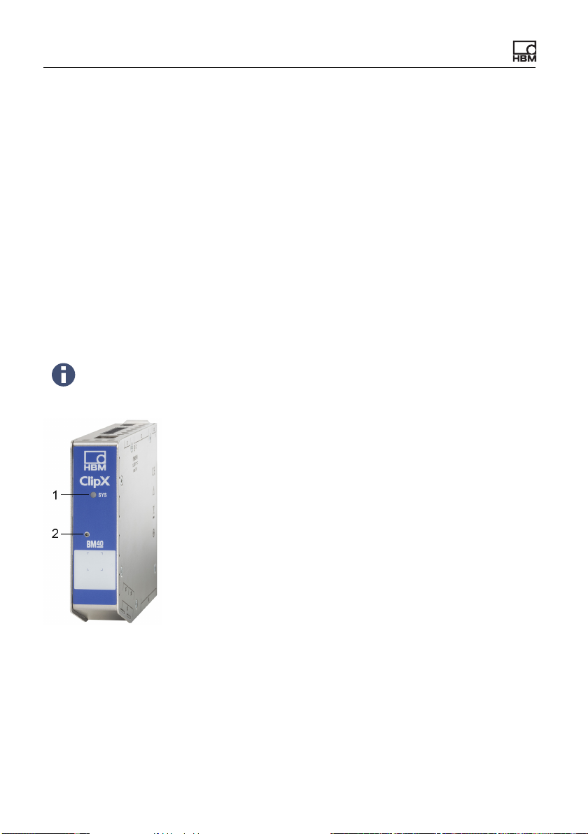
Starting up the ClipX
Example
The IP address of the ClipX is 192.168.169.80, the subnet mask is
255.255.255.0.
Enter 192.168.169.123 as the IP address and 255.255.255.0 as the subnet
mask on the PC.
7.2.4 Resetting Ethernet network settings (DHCP), enabling fixed IP address
You can reset the Ethernet network settings (and only them) to their factory
defaults or enable the fixed (static) IP address 192.168.0.234 (from firmware
2.0). In both cases you must press the Reset button on the front of the ClipX
while powering up.
You can also use the Reset button to temporarily disable user management – see also “User Management” on page 74.
Fig. 34: System LED (1) and Reset button (2)
Resetting the Ethernet settings to their factory defaults (DHCP)
1. Switch off the power supply.
2. Press the Reset button (see picture) using a pencil or a small screwdriver
and keep it pressed while you switch the power back on.
72 A04643_04_X00_00 HBM: public ClipX
Page 75
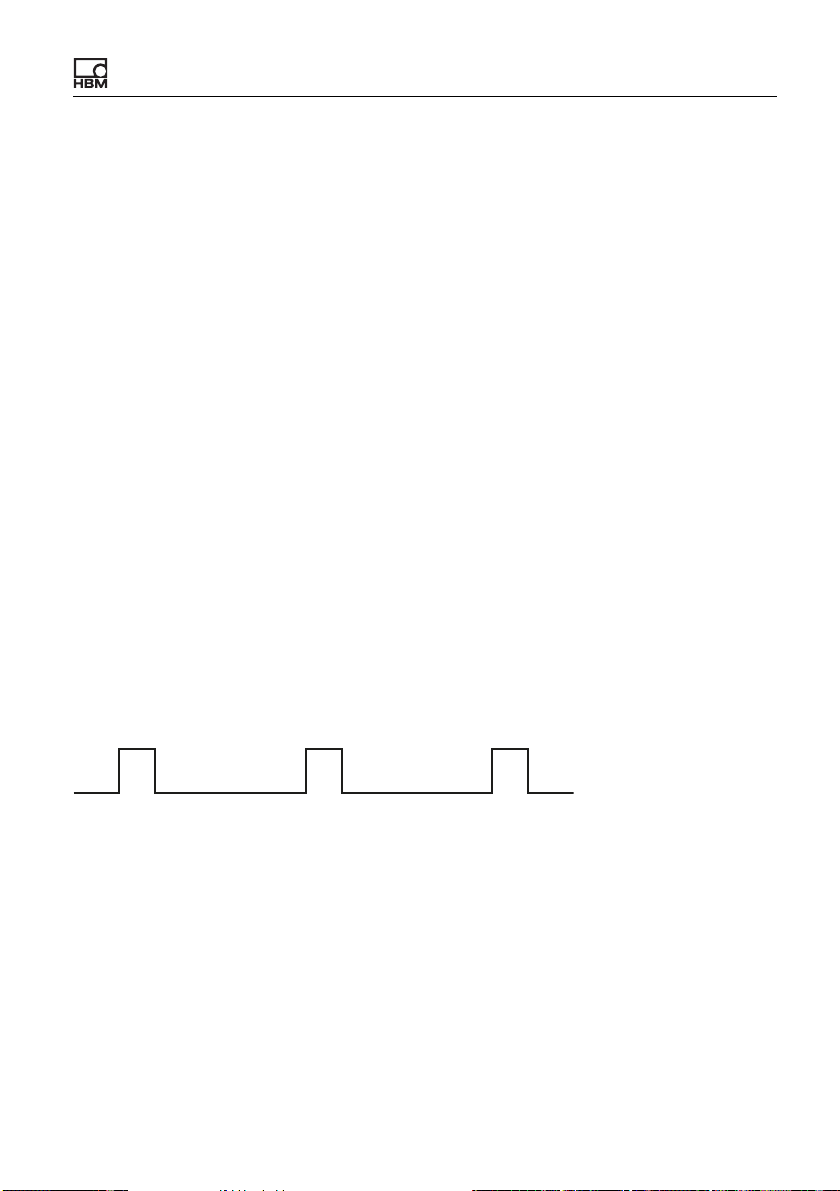
Starting up the ClipX
3. Wait for the system LED to start flickering green before releasing the button.
The ClipX then reboots.
4. Wait for the reboot to complete before connecting to the device.
Ethernet port settings afterwards (factory defaults)
• Use DHCP ("Obtain an IP address automatically", meaning from the server
or via APIPA, i.e. negotiate in the network, if your PC is also using DHCP).
• Device name: ClipX.
• All manual IP address, subnet mask, gateway or DNS settings are cleared.
Enabling fixed ClipX Ethernet address 192.168.0.234 (from firmware 2.0)
1. Switch on the supply voltage.
2. Wait about one minute until the device is ready.
3. Press the Reset button (see illustration) three times using a pen or small
screwdriver. Each press must be held for at least 0.5 seconds, and the
pause between them must not be more than 3 seconds.
4. If the ClipX has successfully detected the button presses, the system LED
flickers yellow and the ClipX reboots. The fixed IP address is then set.
Otherwise, you have up to three minutes in which to repeat the sequence.
5. Wait for the reboot to complete before connecting to the device.
>0.5s
>0.5s >0.5s
<3s<3s
Fig. 35: Sequence of button presses for the fixed IP address 192.168.0.234
Ethernet port settings afterwards
• Fixed IP address (do not use DHCP).
• IP address: 192.168.0.234.
• Subnet mask: 255.255.255.0.
• Device name: ClipX.
• All gateway or DNS settings are cleared.
ClipX A04643_04_X00_00 HBM: public 73
Page 76
Starting up the ClipX
Your PC must be using an address from the range 192.168.0.1 to
192.168.0.233 or 192.168.0.235 to 192.168.0.254 for a connection to
be made.
7.3 User Management
After connecting via the browser, you are initially at the Operator user level
(Symbol ). Click on the icon at the top right of the window to select a different
user level: Maintenance (Symbol ) or Administrator (Symbol ).
User management enables you to restrict access to the ClipX menus through a
browser. The default setting is for no password to be set and you can switch
directly to a different user level. But you can set a different password for both the
Maintenance and Administrator user levels, thus restricting access to the settings.
At the Operator and Maintenance user levels, only the Home and Visualiza-
tion menus are accessible by default. At the Administrator user level all setting
menus are accessible.
If no input is made at the Maintenance or Administrator user level,
the user level is reset to Operator after 30 minutes. The user level is
also reset when you close your browser and reconnect.
Forgotten your password?
You can temporarily disable user management by pressing and holding down the Reset button on the front of the ClipX while logging in or
changing a password (any password is accepted, including a blank
password field). You will normally need a second colleague to press
the button while you are logging in.
See also “Available connections and LEDs” on page 24.
74 A04643_04_X00_00 HBM: public ClipX
Page 77

Starting up the ClipX
Setting passwords and rights
Log in to the Administrator or Maintenance user level and use Change Pass-
word: Select User Level to choose the user level for which you want to set the
password. The length of the password is not actually limited, but it might be that
only a specific number of entered characters can be displayed depending on the
window size. All characters are allowed, including special characters. For security reasons, you must enter the password twice before you can activate it with
CHANGE PASSWORD.
Specify at the Administrator user level the menu items to be accessible at the
Maintenance level by checking the relevant checkboxes. At the Operator user
level no changes can be made; only the Home and Visualization menu items
can be displayed.
You can reset both passwords by loading the factory default setting in
the Device menu (Without network settings is sufficient).
When connecting via the fieldbus interface, you can enable the Maintenance or
Administrator user level directly for the browser by one command, without
entering a password. When doing so, you must specify a time for which the
password deactivation is to apply, up to a maximum of 24 hours. You can also
disable the selected user level prematurely, or extend the time period. The
active user level is also available in the browser as from the time of switching
and for the specified period of time, and is displayed accordingly. The setting via
the fieldbus has priority over any setting made in the browser.
See “Object dictionary” on page 149.
For the connection via the fieldbus itself you do not need a password; all functions are always accessible there.
ClipX A04643_04_X00_00 HBM: public 75
Page 78
Starting up the ClipX
7.4 Setting the ClipX using a web browser
Click on to switch language.
You make all the settings for sensors and signal processing in your browser.
You can view help on each topic by pressing F1 or clicking on . Click on to
make the SYS LED of the ClipX being used flash red/green if you have connected multiple ClipX devices.
The start screen of the ClipX displays the current measured values (gross and
net signals), peak and captured values, the status of the limit value switches
and the digital inputs and outputs, as well as the values of the calculated channels and the values transmitted over the bus systems. If no valid values are
received from one of the data sources, INVALID is displayed.
The net signal (default) is additionally displayed in graph form. Click on the signal name to display a different signal (the setting is not saved). It is not currently
possible to change the display rate or the scaling. is additionally displayed if the transducer has a TEDS module and it has been successfully read.
TEDS
After connecting via the browser, you are initially at the Operator user level
(Symbol ). Click on the icon at the top right of the window to select a different
user level: Maintenance (Symbol ) or Administrator (Symbol ).
After making the ClipX device settings in your browser, save them all to
your PC by choosing Device Storage from the menu.
7.4.1 Assistant to measure sensors
The Assistant menu option will help you to measure your sensor if you do not
have a calibration protocol or you want to measure the sensor when installed.
Before measuring, set the sensor type in the Amplifiers menu to enable the
ClipX to perform measurements. Also specify a suitable low-pass filter, e.g.
10 Hz for static measuring, so as to obtain the most stable possible measure-
76 A04643_04_X00_00 HBM: public ClipX
Page 79

Starting up the ClipX
ment values. For dynamic measuring, you must select the filter matching your
signal frequencies and process.
The assistant provides two measurement variants:
1. Mode: Static
Two points are measured: the value with the sensor under no load and the
value with the sensor under load (force/pressure/torque, etc.). The measurement itself is performed over a period of about 6 seconds with the filter
set in Amplifiers. The calculated mean value and the (sample) standard
deviation are displayed both during and after the measurement process.
2. Mode: Dynamic
This mode is suitable when you are not able to apply a constant load
(force/pressure/torque, etc.). The peak values are calculated over your
measuring time and displayed.
You can either enter the physical value of the load manually or import it over the
ClipX bus or via one of the interfaces.
Procedure
1. Select the Mode.
2. Choose whether you want to enter the reference values manually or import
them.
3. Either enter the reference values (the unit will be applied from the Amplifiers
menu, though you can change it here) or specify the signal source for the
reference values (e.g. from the ClipX bus).
4. Start the measurement.
In static measuring mode, the sensor is first measured under no load. Then
you must apply a load to the sensor and start the second measurement.
You can stop dynamic measuring mode when the minimum and maximum
values have been reached at least once.
5. When the measurements are complete, you can either accept the measured
values and click APPLY or start a new measurement cycle.
The already measured values will then be set off against the new values
(averaging).
The window closes when you click APPLY.
ClipX A04643_04_X00_00 HBM: public 77
Page 80

Starting up the ClipX
7.4.2 Calculation functions
Specify your calculations by choosing Calculated Channels from the menu.
You can create up to six calculations, and output up to six result channels plus
eight digital flags (the 6x6-matrix calculation already delivers up to six result
channels). Each calculation is executed 1000 times per second.
Procedure
1. Click on one of the six lines at the top of the window under Function
Blocks.
2. Select one of the calculation functions under Select Function Type.
3. Select the inputs or numerical values you want.
If you need more constants than those already available (internal constants), you must first specify the number at the bottom of the window in the
User-defined Constants area. You can create up to 10 custom constants
and assign them suitable names.
The formula for calculating the respective function indicates how the variables x1, x2 etc. will be used. Check that all variables have corresponding
values, even if they are not used. Otherwise, a multiplication by 0 for example might make the preceding variable practically ineffective.
4. Select the channel in which you want the result(s) to be outputted. For digital signal, eight flags (bits) are provided.
5. Give the result channels informative names. Flags cannot be renamed.
Most calculations have only one or two outputs; the logic function NOT has 2
times 2 outputs; for the 6x6-matrix up to six outputs are possible. If the value is
outside the displayable number range, NaN (not a number) is outputted. If one
of the input values is invalid, the result is also flagged as invalid, though the calculation is normally performed and the result outputted. For more information on
this refer to the relevant calculations.
78 A04643_04_X00_00 HBM: public ClipX
Page 81
Starting up the ClipX
Click on DELETE below the calculation formula to be able to assign a
calculation a different function type. To avoid accidental deletion, the
button changes to CONFIRM DELETE, and you have to click it again.
Sequence of calculations
The sequence of the functions at the top of the window decides when which calculation is made. It does not matter which of the six function blocks you define
the calculation in. Change the sequence using UP or DOWN below the
calculation formula.
7.4.2.1 6x6 Matrix
Calculates six output signals from up to six input signals by means of a matrix.
For x1 to x6 Select the input channels and for y1 to y6 select one of the six available calculated channels in order to output the relevant result channels.
You can use the calculation to compensate for the crosstalk of a multi-component force transducer in the output signal. Enter only the coefficients (axx) in the
dialog table. Use 0 for unused coefficients. For example, if you do not need
input x6, set every ax6 (a16 to a66) to 0.
If one of the source signals is invalid, all the output signals will become invalid
as well.The calculation will nevertheless be performed and the result exported.
7.4.2.2 Tolerance window
The tolerance window combines several functions: Acquisition of minimum,
maximum, peak-to-peak and arithmetic mean and monitoring of exceeding/undershooting a limit for a definable period of time. You can also determine
the value of another channel when an extreme value is reached.
Note: If you do not want to use any channels to define the level values for level
monitoring, first define the levels with User-defined Constants (Calculated
Channels menu at bottom).
ClipX A04643_04_X00_00 HBM: public 79
Page 82

Starting up the ClipX
Procedure
1. For Input, enter the channel to be monitored.
2. For Start with define a digital signal that starts the functions on a rising
edge. All output signals (min, max, etc.) and the flags for level monitoring
are reset at the start.
3. For Stop with define a digital signal that stops the functions on a rising
edge. All output values (min, max, etc.) and the flags for level monitoring are
frozen at the stop.
4. If you want to determine the value of another channel when a (new) minimum or maximum is reached, specify the channel for Hold Channel.
5. If you want to use the monitoring functions, specify the Threshold High
and/or the Threshold Low.
6. Finally, specify the outputs and flags for the desired results.
Function
After the start, all values and the flags are first reset. Then the signal at the
Input is checked for minimum and maximum and the oscillation bandwidth and
mean value are calculated. The mean value is calculated across a maximum of
100,000 values (100 s). The amount of time between a start and the corresponding subsequent stop is measured as Duration in milliseconds.
The Input is also monitored for exceeding or undershooting the high and low
thresholds. If the relevant limit is exceeded or undershot during the runtime, the
corresponding flag is set.
If you specify a channel for Hold Channel, its value when a minimum or maximum of the channel specified for Input occurs will be retained until the next
occurrence of an extreme value (Captured at Min or Captured at Max).
At stop, all the output values and flags are frozen, which means they remain in
their final status.
If the Input source signal becomes invalid, the peak values and the mean value
are captured and marked as invalid. The Duration output is not influenced by
this. The Hold Channel is not checked for validity.
If the Duration (time between start and stop) is more than 100 s, the mean
value is no longer updated and is marked as invalid.
80 A04643_04_X00_00 HBM: public ClipX
Page 83
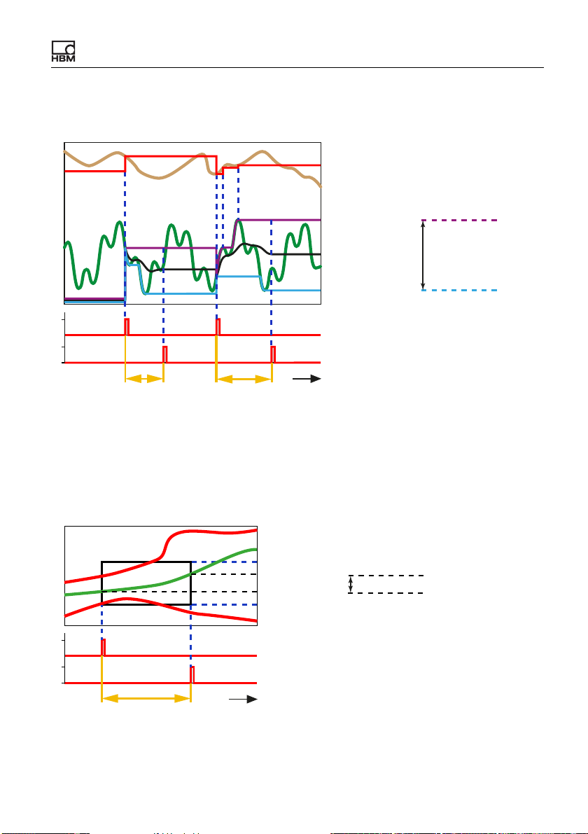
Starting up the ClipX
Example 1: Determining minimum, maximum and mean value, outputting cap-
tured value at maximum
Captured
at Max
Hold Channel
Maximum Value
Mean
Input
(Meas. signal)
Minimum Value
1
0
1
0
t
Duration Duration
Start
Stop
Peak-to-Peak
Fig. 36: Tolerance window; Determining minimum, maximum and mean value
Example 2: Monitoring for undershooting (Threshold Low) and overshooting
(Threshold High). OK/NOK is evaluated via the Threshold High/Threshold
Low flags. The values for Maximum Value, Minimum Value, Peak-to-Peak
and Mean are additionally available.
1
0
1
0
Duration
t
Threshold High = 1 → NOK
Input OK
Threshold High
Maximum Value
Minimum Value
Threshold Low
Start
Stop
Peak-to-Peak
Fig. 37: Tolerance window; Monitoring for underflow and overflow
See also “Peak with capture” on page 82
ClipX A04643_04_X00_00 HBM: public 81
Page 84
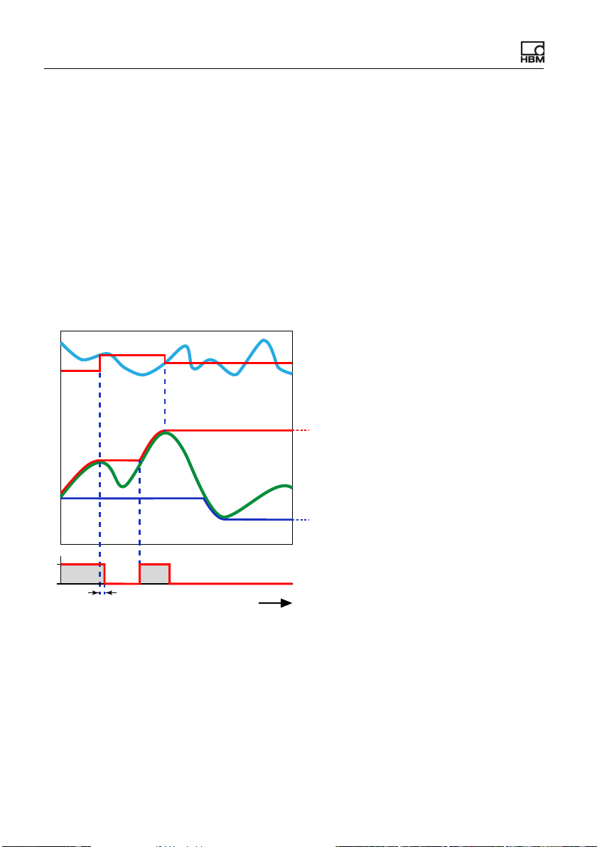
Starting up the ClipX
7.4.2.3 Peak with capture
This calculation determines the minimum, maximum or oscillation bandwidth of
a signal. You can also have the value of another channel (Hold Channel) determined when an extreme value is reached (output signal Captured Value). You
can tell by the falling edge of the peak flag (about 1 ms after detection of a new
peak value) that a new peak value has been found. As long as the measured
value continuously rises (in case of maximum) or falls (in case of minimum) the
peak flag is High (1).
Select the desired function and if necessary create a digital input to reset the
value (level-controlled, in case of High (1), Reset by). Set Reset on to Low
level to reset as long as a Low signal (0) is active.
Captured Value
(Mode: Maximum value)
Signal at
Hold Channel
Peak Value
(Mode: Maximum value)
Signal at
Input
Peak Value
(Mode: Minimum value)
1
0
ca. 1 ms
t
Peak Flag
(Mode: Maximum value)
Fig. 38: Peak value with capture (example)
You can use the Reset by input to capture no new (peak) value at specific
times, leaving the current one instead. This is equivalent to temporarily deacti-
vating the memory function. The capture takes place level-controlled at High (1),
unless you are using Hold on: Low level, capture takes place as long as a Low
signal (0) is active.
82 A04643_04_X00_00 HBM: public ClipX
Page 85
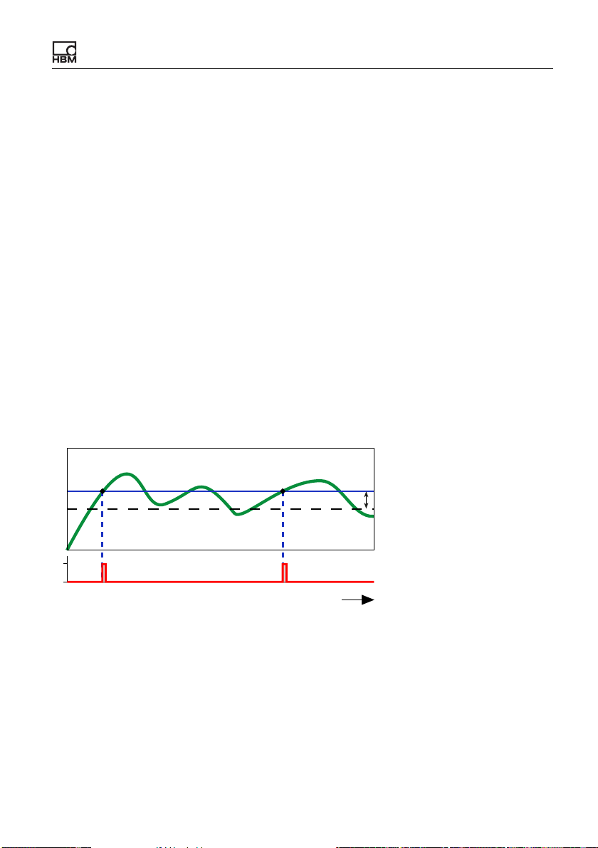
Starting up the ClipX
If the source signal Input is invalid, no analysis is carried out. If the signal of the
Hold Channel is invalid at the time of a peak value, the value is stored, but is
marked as invalid.
7.4.2.4 Trigger
The calculation monitors whether an analog signal exceeds and/or falls below a
limit value. You can monitor two limit values with the function. Use the hysteresis to prevent signal noise from generating multiple trigger pulses. As soon as a
limit value is exceeded and/or undershot, a pulse (lasting 1 ms) is outputted on
the trigger flag. As long as the signal remains within the hysteresis, no further
pulse is triggered. The Hysteresis is below the limit value in the case of Above
threshold and above in the case of Below threshold. In Above or below
threshold mode the hysteresis is both above and below (example 2).
If the source signal is invalid, no pulse is generated. The values for limit value
and hysteresis are not checked.
Example 1: Above threshold mode
Signal at Input
Threshold
Hysteresis
1
0
t
Trigger Flag
Fig. 39: Trigger condition is Above threshold
Example 2: Above or below threshold mode
ClipX A04643_04_X00_00 HBM: public 83
Page 86
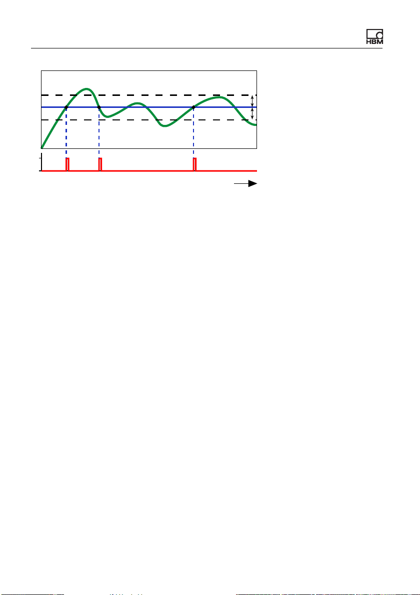
Starting up the ClipX
Signal at Input
Hysteresis
Threshold
Hysteresis
1
0
t
Trigger Flag
Fig. 40: Trigger condition is Above or below threshold
7.4.2.5 Automatic mean
The calculation filters an easily usable signal from a severely fluctuating or noisy
signal by using a specific segment of the signal curve to compute a mean value.
This enables you to reduce the impact of overlaid interference. You can also
define a range in which the signal is averaged and used as the zero value for
further measurements.
You have two options in each case for starting measurement and zeroing:
1. By a limit value.
2. By a digital signal.
You can also combine the methods, i.e. start measuring a mean value, min/max
etc. by way of a limit value and start zero measurement by a digital signal.
If you do not want monitor the start and stop of the calculation via a digital signal, set Enable by to 1 (internal constant) and Start on to High level for example. The calculation is then performed whenever the conditions (Threshold or
Start Measure/Start Zeroing with) are met.
Maximum Value, Minimum Value, Peak-to-Peak and Mean are the values
determined during the measuring time via the signal at the input. The Offset is
the mean value over the Zero Tracking Time. The Status contains an identifier
for the current status of the calculation – see diagram and table below. The
Measured Value is continually updated throughout the time (current measurement value).
84 A04643_04_X00_00 HBM: public ClipX
Page 87
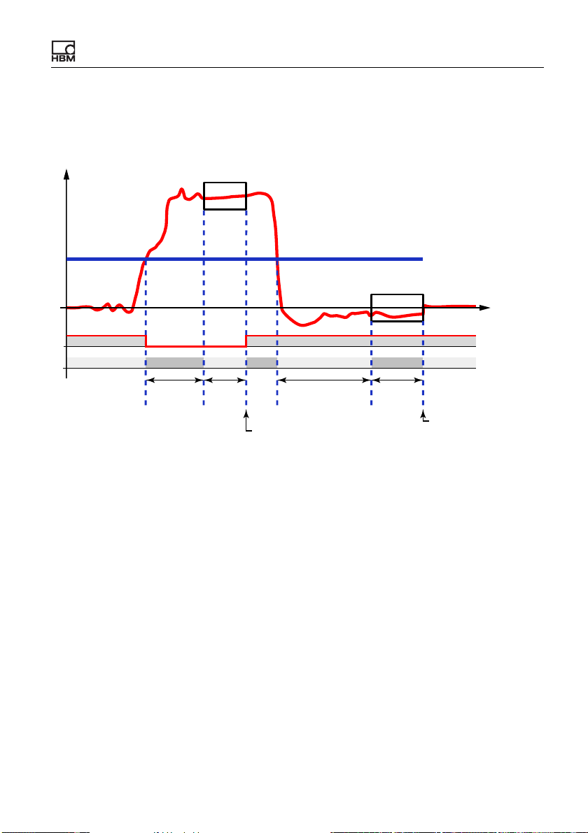
Starting up the ClipX
After a restart (Device menu), a zero measurement is first performed with the
duration of Zero Tracking Time.
Start by a limit value
Threshold
Signal at
Input
0
1
0
Measured Value
t
Ready Flag
Status 23456 72
Meas.
Delay
Meas.
Time
Zero Tracking
Delay
Update of Maximum Value,
Minimum Value, Peak-to-Peak
and Mean
Zero
Tracking
Time
Update Offset
Fig. 41: Automatic mean; Start via limit value
The specified limit value is used in the example for both start conditions. Use a
User-defined Constant (Calculated Channels menu at bottom) for the limit
value. Also set the Start Measure with and Start Zeroing with conditions to 0
(internal constant).
ClipX A04643_04_X00_00 HBM: public 85
Page 88
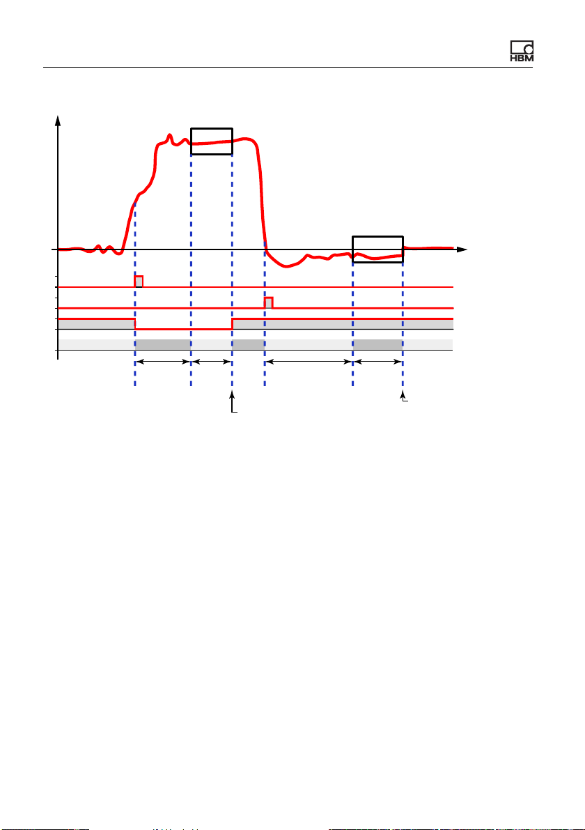
Starting up the ClipX
Start by digital signals
Signal at
Input
0
1
0
1
0
1
0
Measured Value
t
Start Measure
Start Zeroing
Ready Flag
Status 1, 2 3 4 5 6 7 1, 2
Meas.
Delay
Meas.
Time
Zero Tracking
Delay
Update of Maximum Value,
Minimum Value, Peak-to-Peak
and Mean
Zero
Tracking
Time
Update Offset
Fig. 42: Automatic mean; Start via digital signals
Specify a digital signal (digital input, limit switch or flag) for the Start Measure
with and Start Zeroing with conditions. As soon as a channel is entered here,
any specified limit value is ignored for the condition in question. The inputs are
triggered by an edge from Low (0) to High (1). A constant value deactivates the
input.
86 A04643_04_X00_00 HBM: public ClipX
Page 89
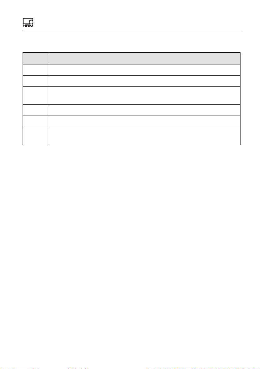
Starting up the ClipX
Status
Value Explanation
1, 2 Wait for start of measurement or limit value overshoot.
3 Wait for the end of the delay measurement.
4 Status during measuring time. When the measurement is complete, the
maximum, minimum, peak-to-peak and mean values are updated.
5 Wait for start of zero measurement or limit value undershoot.
6 Wait for the end of the delay zero measurement.
7 Status during zero measurement. When the zero measurement is complete,
the offset is updated.
7.4.2.6 Physical work
The calculation determines the (physical) work over a specific period from the
two quantities of force and distance (or for example torque and angle of rotation). The force must act along the distance. You will need the measurement values of a different channel for the calculation, e.g. via the ClipX bus.
For Start with define a digital signal that starts the function on a rising edge. At
the start, all output signals are reset to zero. Then the work done since the start
is calculated (∫ F(s) * ds where F = force and s = distance) and outputted in
Work. For Stop with define a digital signal that stops the calculation on a rising
edge. At stop, all output signals are frozen.
Normally, the Work value will steadily increase during the runtime. But if one of
the source signals – that is, either the force or the distance for example –
becomes negative, the work decreases again. In this case Work Max (maximum work value between start and stop) will have a different value than Work.
Additionally, the maximum force and distance are always calculated and outputted during the runtime.
If one of the source signals is invalid, all the output signals will become invalid
as well. The calculation is aborted in this case, and you have to restart it with a
new start signal.
ClipX A04643_04_X00_00 HBM: public 87
Page 90

Starting up the ClipX
7.4.2.7 Adder, Multiplier and Divider
Multiplies up to four source signals and adds together up to four of those terms
in its adder/multiplier function. You can use constants as source signals to multiply channels by a factor (e.g. -1 for subtraction). Set inputs for terms you don't
need to 0 (internal constant); set all others to 1.
In the divider function two terms are divided. The dividend adds together up to
three terms, for each of which 2 inputs are multiplied; the divisor adds together
up to three inputs. Set inputs for terms you don't need to 0 (internal constant);
set all others to 1.
Output = dividend/divisor
In addition to the "normal" division, a modulo division is carried out. This modulo
division checks how often the divisor is fully included in the dividend and determines the Residual z. When you divide 11 by 4, for example, the 4 is included
twice in 11, and 3 is produced as the Residual z (2 x 4 = 8, 8 + 3 = 11).
If one of the source signals is invalid, all the output signals will become invalid
as well.The calculation will nevertheless be performed and the result exported.If
the result is outside the number range, NaN (not a number) is outputted.
7.4.2.8 Counter
Counts the edges (rising/falling/both) of a digital signal. Use Start/Stop with to
interrupt the count.
Timeout after: If you enter a time greater than 0, after that time the counter is
reset if no edge has occurred by then.
With Threshold Value for Flag you can set a flag when a specific count is
reached.
88 A04643_04_X00_00 HBM: public ClipX
Page 91
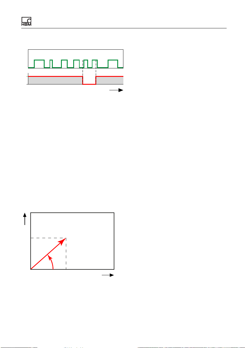
Example:
Input signal
Starting up the ClipX
Rising: 5
Falling: 6
Both: 11
1
0
t
Start/Stop
Fig. 43: Example for the counter function
If the maximum counter reading (107) is exceeded, the output signal becomes
invalid and the counter stops. After a timeout or reset, the counter restarts.
7.4.2.9 Cartesian to polar coordinates
The calculation converts two input channels representing the position (x, y) of a
point in the Cartesian coordinates system into the corresponding polar coordinates. You will need the measurement values of a different channel for the calculation, e.g. via the ClipX bus. The calculation results in two output channels:
one with the angle values (θ, theta) and one with the radius values (r). The value
range for the angle extends from -179.99° to +180°. Multiply the value by π/180
as necessary to get the radian measure (rad).
y
y
r
θ
x
x
Fig. 44: Example for coordinates transformation
If one of the source signals is invalid, all the output signals will become invalid
as well.The calculation will nevertheless be performed and the result exported.
ClipX A04643_04_X00_00 HBM: public 89
Page 92
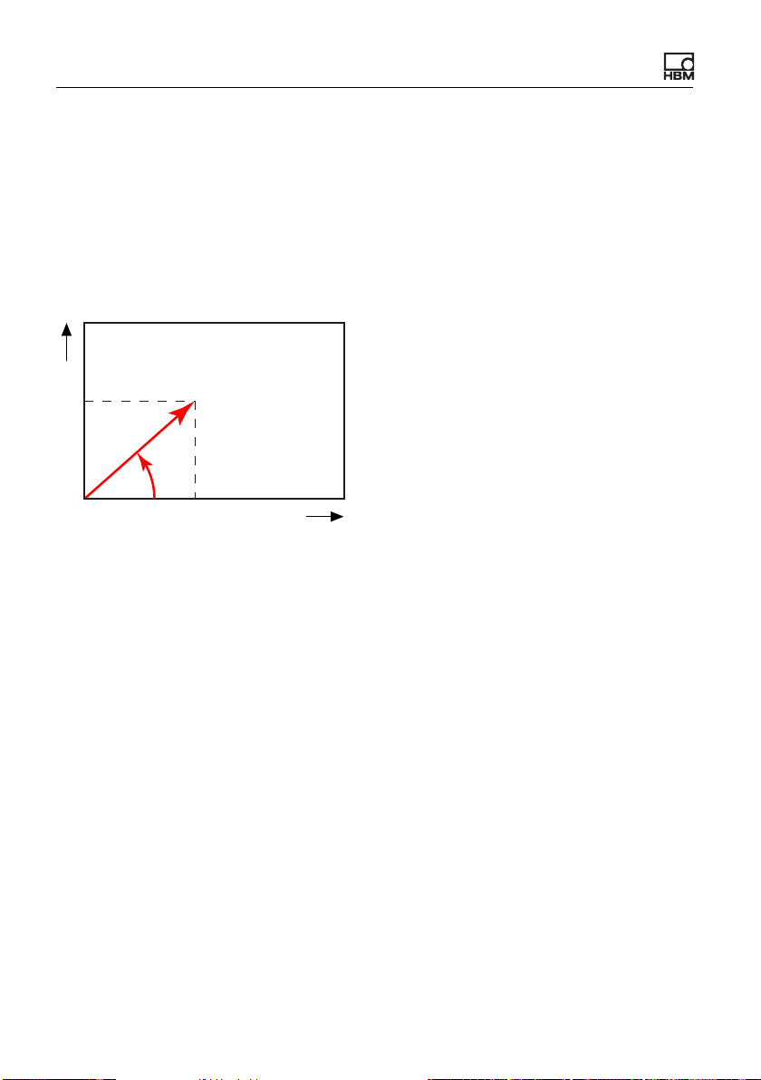
Starting up the ClipX
7.4.2.10 Polar-to-Cartesian coordinates
The calculation converts two input channels representing the position (Radius r,
Angle θ = theta) of a point in polar coordinates into the corresponding Cartesian
coordinates. You will need the measurement values of a different channel for
the calculation, e.g. via the ClipX bus. The calculation results in two output
channels: one with the x values and one with the y values. The angle value
must be in degrees (-360° to +360°).
y
y
r
θ
x
x
Fig. 45: Example for coordinates transformation
If one of the source signals is invalid, all the output signals will become invalid
as well.The calculation will nevertheless be performed and the result exported.
7.4.2.11 PID controller
This calculation implements a PID controller in parallel structure. The PID (Proportional Integral Derivative) controller consists of three elements: the P term, I
term and D term. The parallel structure of the controller prevents a wind-up
effect. You can limit the output signal via Y
max
and Y
. When one of the values
min
is reached the Min/Max Flag is set. Td is the parasitic time constant at 1/update
rate = 1 ms.
90 A04643_04_X00_00 HBM: public ClipX
Page 93
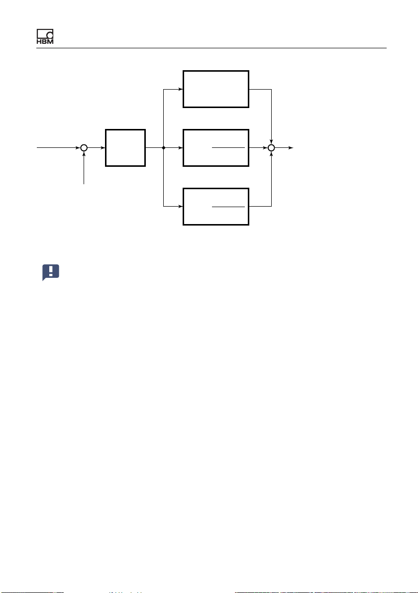
G(s) = 1
Starting up the ClipX
Set Point
Process
Value
T
d
1
T
*s
i
T
*s
d
*s + 1
+
-
K
p
G(s) =
G(s) =
+
+
+
Regulating
Variable
Fig. 46: Block diagram of the PID controller
You cannot define the PID controller as a simple P controller. At least
one I element must be present in addition (Ti ≥ 0.01 s).
If either the target value or actual value is invalid, the controller stops and the
value is marked as invalid. However the output retains the last value. In the case
of Enable by: 0 the controller is reset and the value of Y
is outputted. This
Default
input has priority over the Start/Stop with signal.
7.4.2.12 Signal generator
This calculation generates a periodic signal, for example a sine wave. Determine the desired frequency, amplitude and, if applicable, an offset. Signal forms
available are sine, square wave, triangle, counter, constant and (white) noise.
The signal on Start/Stop with together with Start on determines whether the
selected function will be outputted. When Start on: High level) is set, on a Low
ClipX A04643_04_X00_00 HBM: public 91
Page 94

Starting up the ClipX
level (0) the output is stopped and the Offset value is outputted. When the signal switches back to High (1), a new output period begins.
Use 100 Hz (1/10 of the update rate) as the maximum frequency, otherwise the output signal will not be formed from enough points. This results
in a distorted curve shape (stairway effect) for a sine wave.
Example: Sine with amplitude 50 and offset 50
The amplitude fluctuates sinusoidally between 0 and 100 at the set frequency.
If the result is outside the number range, NaN (not a number) is outputted.
Counter function
At an offset of 0 the counter generates a number between -Amplitude and
+Amplitude that is incremented by one each time by the update rate (1000 Hz).
Any entered frequency is ignored.
White noise function
The noise signal is generated by a hardware noise source (integrated circuit).
7.4.2.13 Pulse-width measurement
This calculation measures the time between two edges. You can use one or two
(digital) channels (flags) as the input. The result can be output as time (seconds
or milliseconds) or as frequency (1/s). Specify the same channel for Start with
and Stop with, and use different levels if you only want to use one input channel.
Maximum resolution (smallest measurement duration): 1/update rate; at an
update rate of 1000/s this is equivalent to 1 ms.
Maximum measurement duration: 600 s. The output becomes invalid and the
calculation is stopped if the maximum measurement duration is exceeded. This
status is reset by the next start signal.
92 A04643_04_X00_00 HBM: public ClipX
Page 95
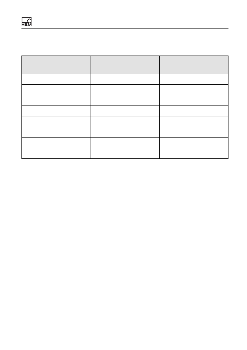
Starting up the ClipX
Pulse duration, corresponding frequency and achievable measurement uncertainty
Pulse duration in ms Frequency in Hz
10 100 10
20 50 5
50 20 2
100 10 1
200 5 0.5
500 2 0.2
1000 1 0.1
2000 0.5 0.05
Measurement uncer-
tainty as a %
7.4.2.14 Timer
After a programmable time (Interval), sets the Timer Flag to active and holds
the level over the Pulse Length before the level is reset to inactive. If you enter
0 for the Pulse Length, the flag is set to active at least for one update interval
(1/update rate = 1 ms). The maximum interval is 200,000 seconds. The Pulse
Length should be shorter than the Interval, otherwise the flag will always be
active as long as the timer is running. Choose Active Timer Flag to set the
Timer Flag to Low (0) or High (1) when active.
Enable by: Depending on the setting of Enable on (High level or Low level),
the timer is only started when the corresponding level applies. In both Single
shot and Continuous mode the timer is stopped (reset) immediately if this level
is no longer active. The values at the outputs are deleted, or reset to 0, in this
case.
The procedure can be run once only (Type: Single shot) or continually
repeated (Type: Continuous) as long as a corresponding signal is active on
Start/Stop with.
ClipX A04643_04_X00_00 HBM: public 93
Page 96

Starting up the ClipX
In the case of single shot and Start on: High level, a positive edge starts the
timer and the next positive edge only restarts the timer when the time has
elapsed. In continuous mode, the timer starts as soon as a High signal (1) is on
Start/Stop with, and immediately restarts at the end of the interval. As soon as
no High signal is active any more, the timer is stopped and is only restarted
when a High signal is received.
In the case of single shot and Start on: Low level, a negative edge starts the
timer and the next negative edge only restarts the timer when the time has
elapsed. In continuous mode, the timer starts as soon as a low level (0) is on
Start/Stop with, and immediately restarts at the end of the interval. As soon as
no low level is active any more, the timer is stopped and is only restarted when
a low level is received.
Both the Timer Flag and the current time value (Time) are outputted: 0 when
the timer starts, the Interval value at the end of the interval. When the timer is
stopped, the interval time is outputted constantly.
7.5 Using parameter sets
You can store up to 10 parameter sets in the ClipX. A parameter set contains
almost all the settings of the various menus for Amplifier (sensors), Calculated
Channels, Peak Values and Limit Switches etc. It does not include the net-
work settings, TEDS usage, the passwords, the visualization, fieldbus and ClipX
bus settings and settings for synchronization of the CF amplifiers.
You can also transfer the parameter sets together with the other device settings
to your PC. Give the parameter sets names so that you can distinguish them
more easily. You can use up to 30 characters per name.
The active parameter set is indicated by ACTIVE, and the start parameter
set by BOOT.
on the second line in the browser window indicates that the original
settings of the current parameter set are no longer being used. Save the
settings to a parameter set so as not to lose them.
94 A04643_04_X00_00 HBM: public ClipX
Page 97

Starting up the ClipX
You can save, load and activate parameter sets via the web browser or the fieldbus interface, or activate them only via the digital inputs.
Processing parameter sets
On a new ClipX all the parameter sets contain the factory setting. You can reset
a (single) parameter set to those defaults at any time by clicking on FACTORY
SETTINGS in the browser while a parameter set is active.
When the ClipX powers up, all the parameter sets are translated into the relevant binary instructions and stored in the RAM in order to enable quick parameter set changing. Then the start parameter set is activated.
Each parameter set is assigned a check digit (CRC, cyclic redundancy check) in
the RAM in order to avoid errors.
It takes just a few milliseconds (<100 ms) to change the active parameter set.
However, in the event of a parameter set switch which changes sensor settings,
filters or the analog output, the measurement status is set to INVALID for
approximately 2.5 seconds so as to suppress transient responses on the outputs. Brief timeouts may also occur on the ClipX bus (SYS LED turns yellow).
7.6 Device storage (Device cloning)
Using the Device storage menu, you can back up all the device settings to your
PC or restore them from it. You can also transfer all the settings to another
device (Device cloning). All settings are saved in the operation. When restoring,
you can choose which settings to restore.
Here you will also find the working standard calibration certificate, the manufacturer’s certificate, the default files for the fieldbuses (PROFIBUS, PROFINET
and EtherCAT), possible log files, and the object directory (clipx_OD.csv). A
new object directory is generated each time prior to downloading so that it contains the current status. As a result, the download takes several seconds.
You can also upload your own files to this area and download them back to your
PC or delete them.
ClipX A04643_04_X00_00 HBM: public 95
Page 98

Starting up the ClipX
Backing up device settings
Click on BACKUP. The ClipX creates a ZIP file. The file name is composed of
the device name, the UUID (serial number) and the current date, e.g.
ClipX_009043-20180424.zip. Depending on your browser setting, you are
prompted to select a folder, or the file is saved to your Download folder.
Restoring device settings
1. Click on REVERT and specify the file containing the desired settings.
2. Activate all lines whose settings you want to load. To load everything, click
on Select all.
• Network: Contain all the settings of the Ethernet port such as IP
address, subnet mask etc., as well as the settings for time (e.g. NTP)
and OPC UA.
• General: Contains the settings for TEDS usage, visualization, ClipX bus
(address and synchronization mode Master or Slave), the number of the
start parameter set, and the settings for parameter set switching by the
digital inputs (where specified).
• Fieldbus: Contains all the settings of the active fieldbus (only BM40IE
and BM40PB).
• Password: Contains the passwords being used for the user levels in
encrypted form.
• User management: Contains the settings (accessible menu items) of
the Maintenance user level.
• Visualization: Contains the settings for the Visualization menu.
• Parameter set 01 … Parameter set 10: Contains the settings of the
specific parameter set.
3. Click on REVERT again.
Saving (uploading) your own files to the ClipX, ClipX memory
Files that you have already uploaded, such as the working standard calibration
certificate, are displayed in this area, and you can choose to save the files on
your PC. Depending on your browser setting, you are prompted to select a
96 A04643_04_X00_00 HBM: public ClipX
Page 99

Starting up the ClipX
folder, or the file is saved to your Download folder. Select a file and click on
DELETE to remove the file from the ClipX memory.
Choose FILE UPLOAD to upload your own files, such as more calibration certificates, to the ClipX. The file name must not contain any special characters
(umlauts) or blanks, only ASCII letters and numbers, dashes (-) and (underscores (_). At least one, and a maximum of 130, characters are allowed. The file
extension must comprise two to a maximum of four characters. You can upload
any file formats. If the upload did not complete correctly, because of insufficient
space for example, the failure is indicated at the bottom of the browser window
and any storage space already occupied by the file is freed up again.
ClipX A04643_04_X00_00 HBM: public 97
Page 100

Starting up the ClipX
98 A04643_04_X00_00 HBM: public ClipX
 Loading...