

Page 1
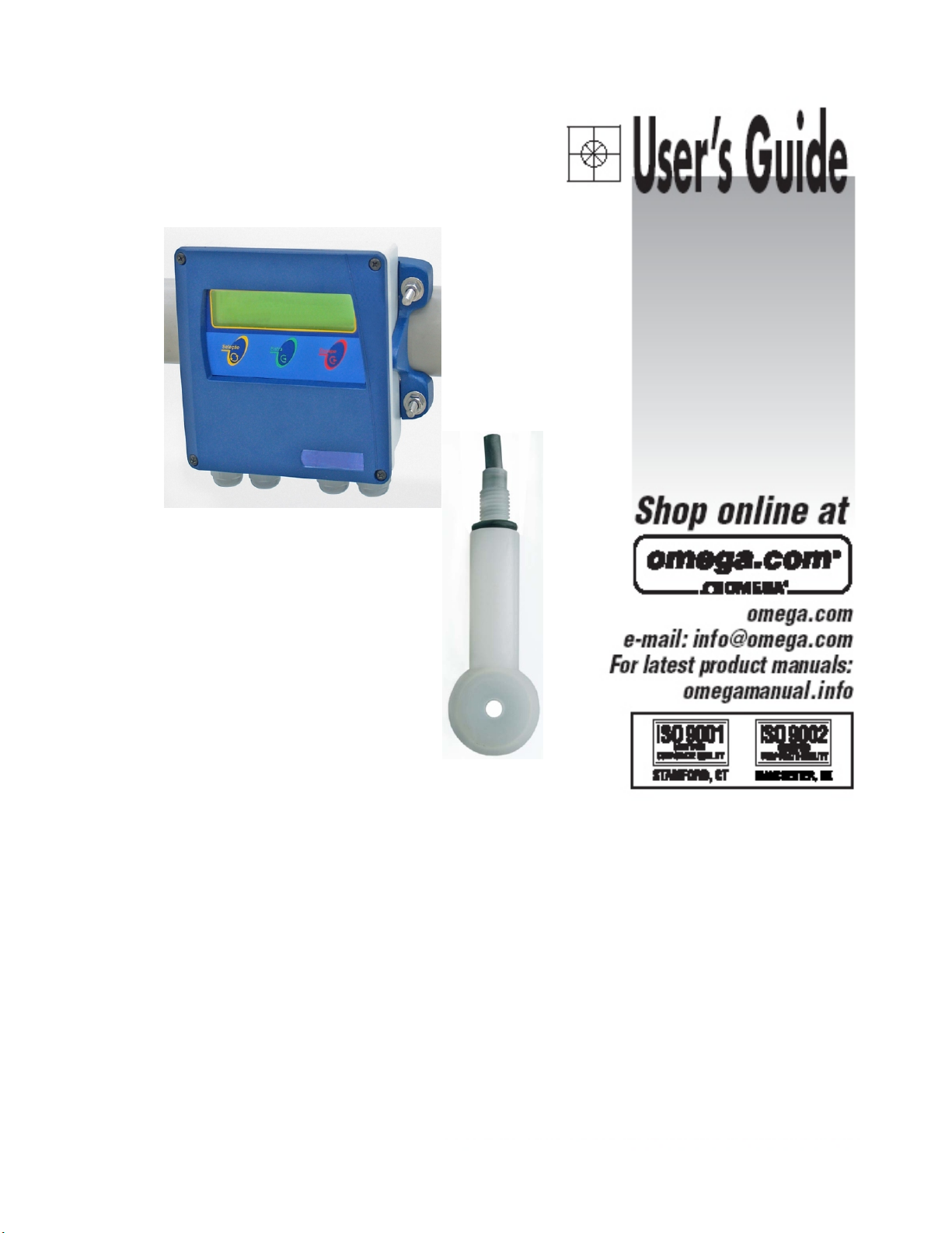
CDCN442
Omega
CDCN442
Concentration Conductivity Meter
Page 2
Page 3

Instruction Manual
Conductivity and Concentration Analyzer
CDCN442
Index
Specifications .........................................................3
Mechanical Description..................................................4
Dimensional ..........................................................5
Typical Installation......................................................6
Electrical Installation....................................................7
Interconnection Barr....................................................8
Electrical Schematic....................................................9
Equipment Operation ..................................................10
Equipment Operation - Concentration Set Up . . . . . . . . . . . . . . . . . . . . . . . . . . . . . . . 14
Equipment Operation - Concentration Calibration . . . . . . . . . . . . . . . . . . . . . . . . . . . . 16
Equipment Operation - Concentration Read. . . . . . . . . . . . . . . . . . . . . . . . . . . . . . . . . 17
Equipment Operation - Conductivity Set Up . . . . . . . . . . . . . . . . . . . . . . . . . . . . . . . . . 18
Equipment Operation - Conductivity Calibration . . . . . . . . . . . . . . . . . . . . . . . . . . . . . . 20
Equipment Operation - Conductivity Read . . . . . . . . . . . . . . . . . . . . . . . . . . . . . . . . . . 21
Cell Maintenance .....................................................22
Communication Protocol................................................23
Troubleshooting ......................................................24
Page 4

2.
General
Case Material Cast Aluminum SAE 323(BASE)
ABS(Frontal Lid)
Finishing Electrostatic Epoxy Paint
Electrical Connection Terminal Barr
Cable Inlet Cable kncokout 3/8” (4x)
Assembly 2" Tube, Flat Surface or Panel
Enclosure IP-68
Power Consumption 3.5 VA
Weight 1.3Kg.
Electrical Power 90 thru 240 Vac ( 50/60 Hz)
Operating Temperature 5 thru 40 ºC
Relative Humidity 20 thru 80%
Analyzer/Transmiter
Display Alphanumeric 2 lines x 16 characteres
Conductivity Ranges 5 thru 2000 mS/cm
Concentration Range Consult list on page 11
Temperature Range 0 thru 200 ºC (Others upon request)
Automatic Temperature
Compensation
0 thru 200 ºC (Others upon request)
Output Signal
Analogic 4 - 20 mA w/ adjustable output range.
Digital RS-485 bilateral thru software up to 36
equipments 2 Km apart.
Galvanic Isolation 2000 VAC (by opto coupler)
Line Resistance 1KOhm
Controler
Actuation Type Frequency Modulation, P+Di
Set-Point 1 independent from 0 thru 100% of scale
Output 1 control ON-OFF
Actuation Type Frequency Modulation, P+Di
Sensor
Type Toroidal (Electrodeless)
Body Material PVDF (Kynar)
Range 10 mS thru 2 S
Temperature (@ Atm. Pr.) 0 thru 100ºC
Max. Pressure (@ 25ºC) 10 Kgf/cm2
Insertion lenght 100mm
Process Connection Threaded Point 2” (CIP and others upon request)
Specifications
R 485
ACCESSORIES: supplied with the equipment : installation hardware (2x), Instruction Manual, SS
Clamps with nuts and washers.
S
3
Page 5
3.
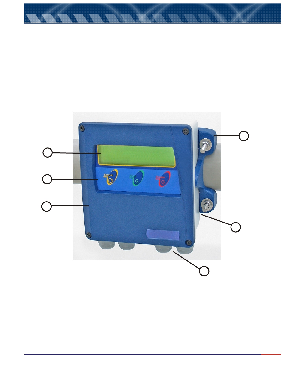
This equipment is offered in SAE-323 aluminum with lower oxidation level, anti corrosion treatment and electrostatic epoxy
paint finishing and frontal lid in ABS . Built in small and light size, complying with IP-68 Standard.
Under the same case you will find: Local Indicator, Analyzer, Transmitter and Controller.
The mounting of the instrument can be done on 2” Tube" or in Flat Surface or Panel (DIN144).
The electrical connection is possible through a terminal block located internally at the lower portion of the case and the
cable knockouts are located in the bottom of the case, 4x 3/8” BSP.
Mechanical Description
6
2
3
1
5
CDCN442
Omega
4
1 - Frontal Lid in ABS.
2 - Display alphanumeric 2 lines x 16 characters.
3 - 3 keys Tactile Membrane Keyboard:
<SELECT>
= Select the desired operation, flashing option.
<ENTER>
= Enter the program commands for analysis, confirm above Selected Function.
<ESCAPE>
= Move back one step at every touch.
4 - Cable knockouts (4) 3/8” BSP.
5 - Aluminum Case (SAE-323)
6 - Installation Hardware for Wall Mounting, 2” tube and panel.
4
Page 6
4.
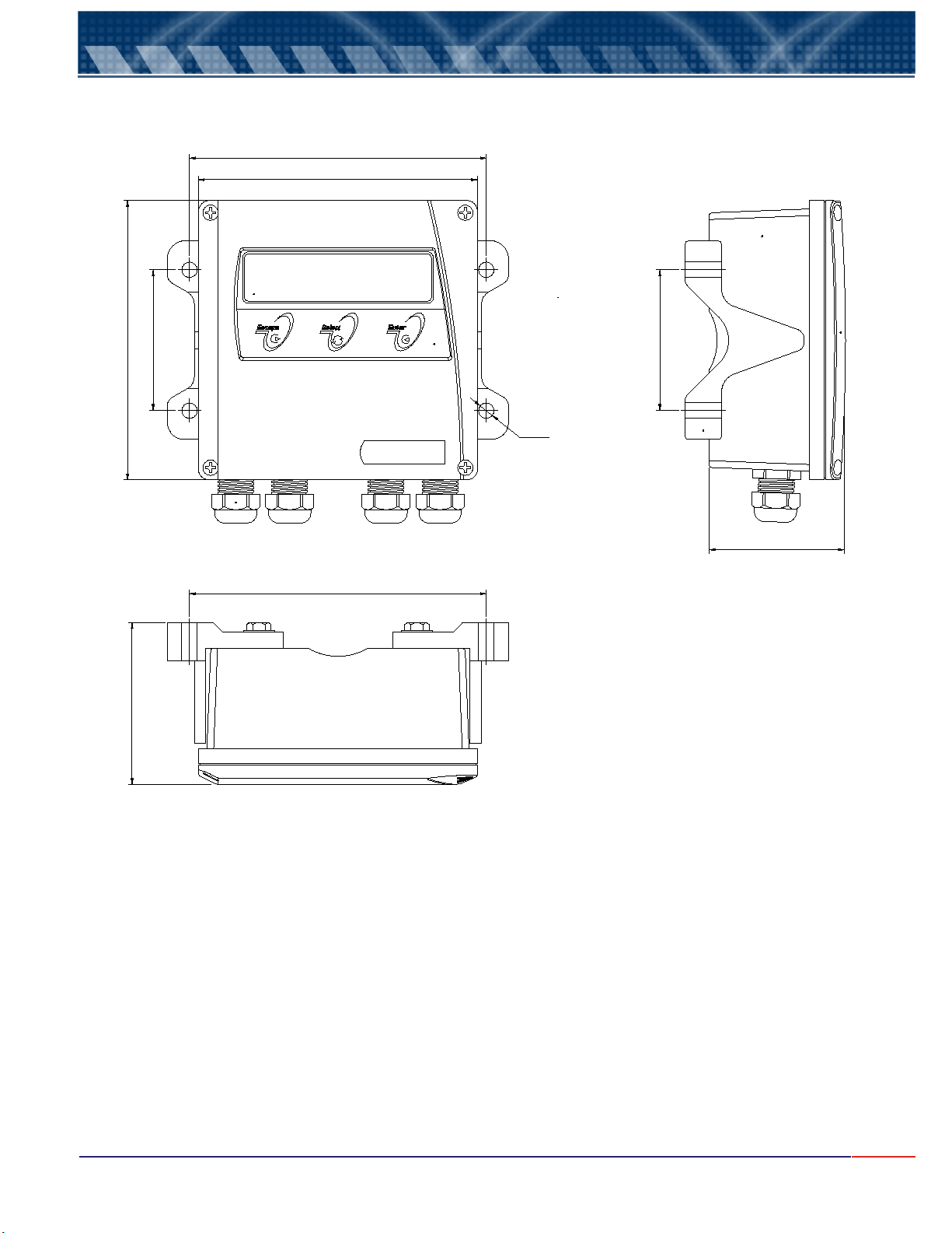
Dimensional
145
¢73
¢154
145
SELECT FUNCTION
Conductivity Analyzer
¢73
Ø8(4x)
CDCN442
70
¢154
Note: Dimensions in millimeters
84
5
Page 7
5.
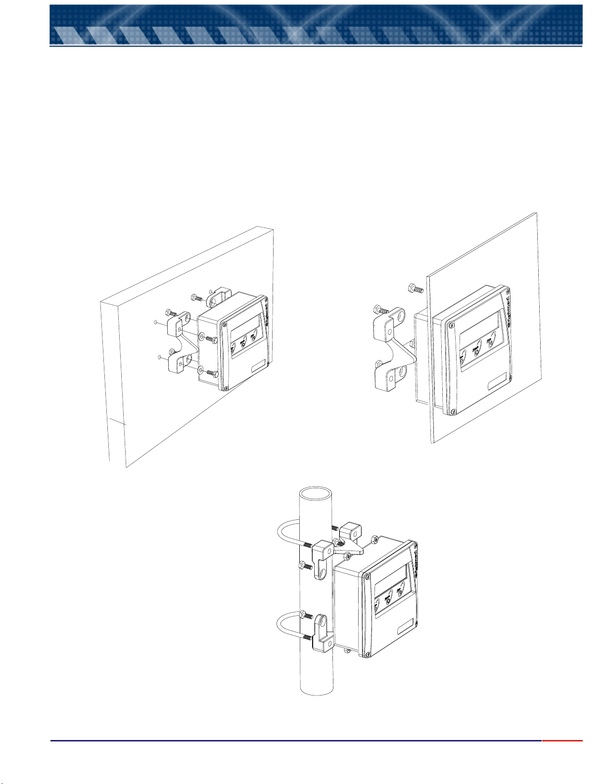
The CDCN442 can be installed in 3 different ways: Panel, 2” Tube and Flat Surface.
For installation purpose the instrument is offered with the following hardware: 2 Installation Support, 4 SS
screws ¼" x ½", 4 plain SS washers ¼", 2 "U" SS clamps , 2 SS screws and 2 SS plain ¼".
These hardware allow 3 different ways for installation, to know:
a) Installation in 2” tube: Uses 2 installation support + 2 "U" clamps with nuts and washers.
b) Installation in Panel: Uses 2 installation support ; the edges will be placed against the internal surface of
the panel, 4 screws. ¼" x ½” will be used to hold it in place.
c) Installation in Flat Surface(Wall Mount): Uses 2 installation support and “U” clamps holes are also used to
Hold the instrument in place at flat surface.
Typical Installation
Flat Surface Installation
2” Tube Installation
Panel Installation
6
Page 8
6.
1- Remove the equipment from the box and inspect for any possible damage caused by the transportation;
2- Install the instrument in an area that offers easy access and handling, exempt of vibrations, following the
installation procedures Topic 5 - Typical Installation - page 6;
3- Avoid exposing the equipment to direct to solar rays and if necessary provide a covering;
4- Verify if the electrical installation is correct, if security hardware is available (circuit breakers);
5- Proceed with the equipment installation.
Electrical Installation
Electrical installation
1- Remove the front lid of the equipment
2- Insert the cables through the cable knockouts, certify that the connections are correct, verifying thru the
identification drawing and the electrical schematic;
3- The wires must be correctly positioned in order to avoid humidity access to the equipment case,
Never mend the Toroidal Cell cables! This may cause reading errors!
Important Recommendations
1.1. The electrical power of the equipment, must be independent from other system components. Being so,
the cable that powers the Control Valves, Solenoids, Alarms and others, must be connected directly to the
Distribution box and "never" at the connection barr of the equipment.
1.2.Verify if the cable knockouts of the equipment and probes are firmly attached to its respective
interconnection cables. This procedure is necessary in order to preserve the enclosure protection (IP-68).
1.3.Be careful with Humidity !!. It diminishes the impedance, generating reading errors. Verify the cable
knockouts and if necessary, dry the interconnection barr using a hair dryer.
1.4.Never cut or mend the cell cables.
1.5.ON-OFF outputs are thyristor type, offering many advantages for the equipment, such as : spark free,
quicker commutation, noise practically zero, exempt of RF interference and many more. Outputs can
commutate any charge, since they are powered by alternate tension (VAC), limited to 250V / 1A.
7
Page 9
7.
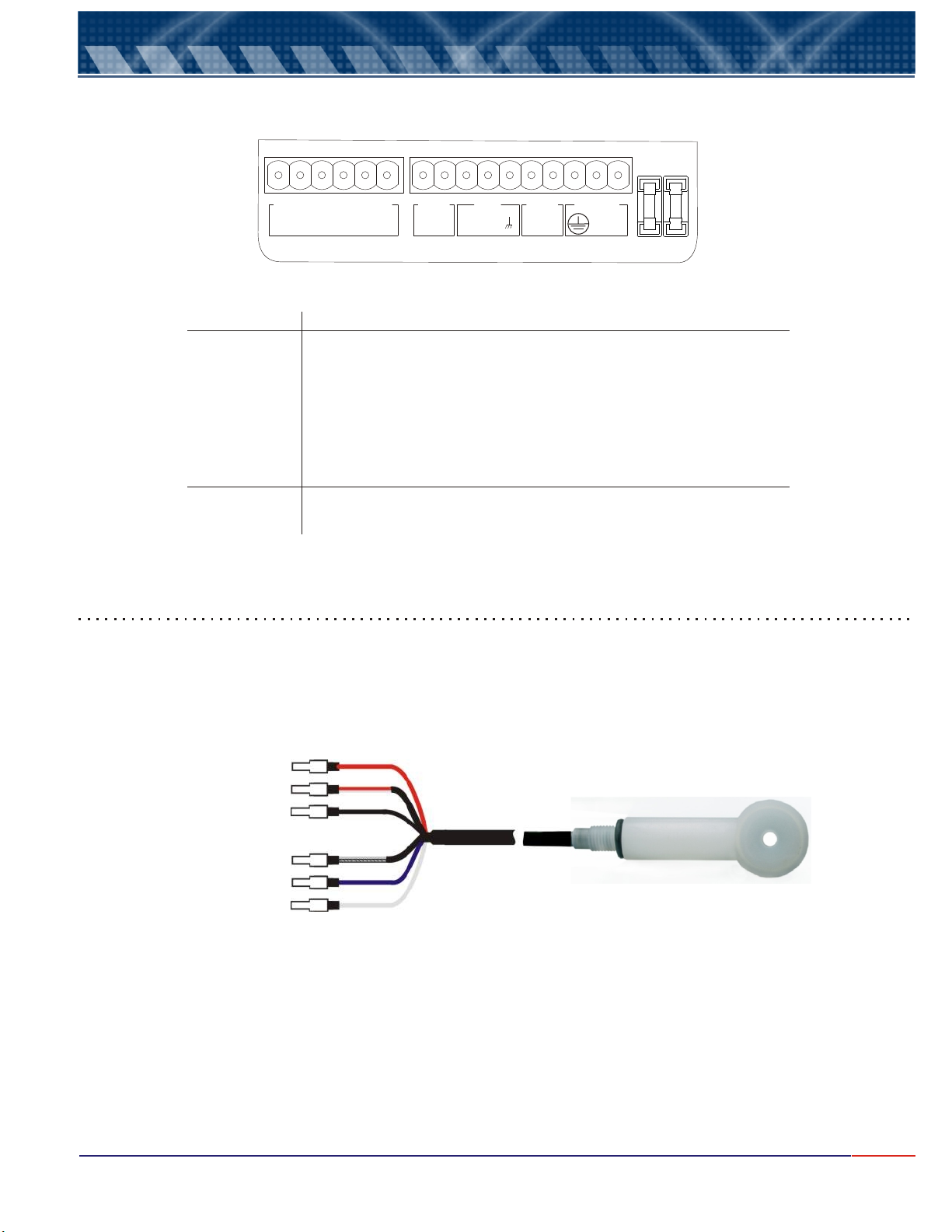
Interconnection Barr
CN
1
CN2
Slots
1 & 2
3
4 & 5
6 , 7 & 8
9 & 10
11 thru 16
Fuses
F1
F2
Coll.
Coll.
BL BLUE
REDBL
1516
14
Coll.
BLUE
RED
13
12
mA
4-+
11
Connections
Electrical Power 90-240Vac - 50/60 Hz
Grounding
Set Point 1Output (SP 1)
Digital Rs485 Output
Transmission Output 4 - 20mA
Toroidal Cell Connection
Connections
General Fuse (1A / 250V)
Set Point 1 Fuse (1A / 250V)
20
910
8 6
RS485 SP1
+
C
5
7
4
O
N
3
2 1 F2F1
AC
CDE-442 Cell Connection to the Inteconnection Barr
The CDE-442 cable cell offers terminal pin type, in order to be screwed in a connector Conexell Type 6 pins.
For the connection, insert the cell cable and screw the terminals at the connector obeying the numerical
sequence identified below.
Red(13)
Colorless (14)Red
Black(15)
Colorless Black(16)
Blue (11)
Colorless Blue (12)
After connecting the cell at CN1 at the interconnection board, tie the cable knockout firmly.
8
Page 10
8.
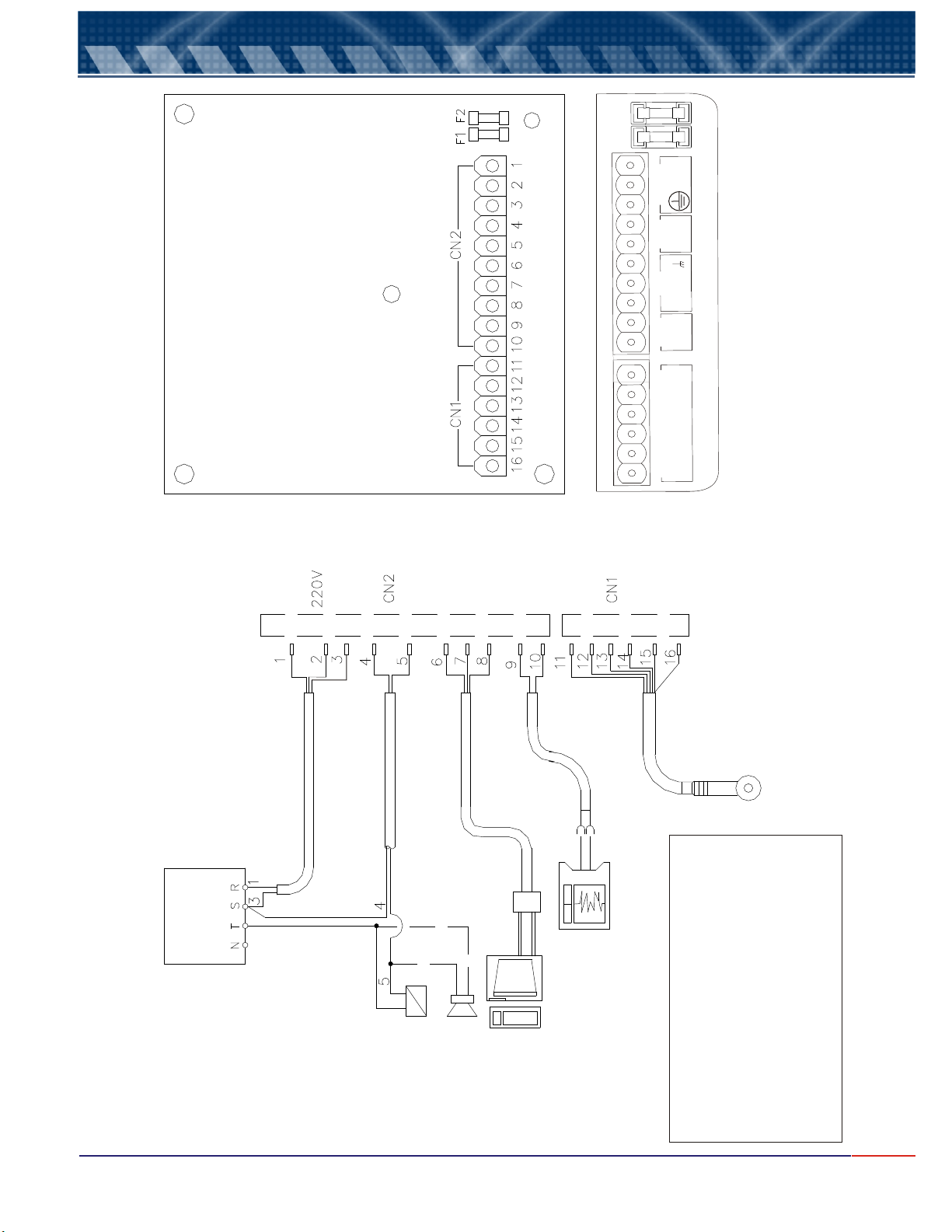
Electrical Schematic
MAIN BOARD
2
F
1
F
1
AC
2
3
N
a
4
1
P
S
C
5
2
N
C
1
N
C
Connectors Description
6
5
+
8
4
7
S
R
-
8
+
2
0
9
A
m
4
0
1
e
1
1
Blu
.
ue
oll.
l
2
B
C
1
d
3
R e
1
l;
olC
4
ed
R
1
5
Blac
1
.
c
oll
6
Bla
C
1
F2 = 1A / 250V (S P1)
F1 = 1A / 250V (GENERAL)
g
n
i
r
e
w
r
o
t
e em
l
e
n
F a
Con c
Note: it is important to use independent
phases and cables for
equipments and control or
alarm valves.
ELECTRICAL
DISTRIBUTION
BOX
o
P
e 1l
b
a
C
d
n
u
Gro
l
b e 4
a
3
e 2l
b
a
C
l
Cab e
C
32
2
RS
Converter
5
48
s
R /
Graphic Register
5l
e
b
a
C
or PLC or SDLC
l
a
l
d
l
i
e
r
C
To o
Controller
or
Alarm
PC
Pin Color Description:
Pin# Color
11 Blue
12 Colorless Blue
13 Red
14 Colorless Red
15 Black
16 Colorless Black
9
Page 11

9.
Element Range
HNO
3
0 thru 280 g/L
HF 0 thru 300 g/L
NaOH 0 thru 150 g/L
NaOH 150 thru 500 g/L
H2SO
4
0 trhu 300 g/L
H2SO4 350 thru 800 g/L
H2SO4 940 thru 998 g/L
H2CrO
4
0 thru 100 g/L
NaCL
0 thru 260 g/L
K2CO3 0 thru 315 g/L
Na2SO4 0 thru 220 g/L
HCL 200 thru 350 g/L
Equipment Operation
Important Information
1-While at Reading, it is possible to obtain the following information:
When key is pressed, it is possible to obtain the Set Point and transmission values.
If key is pressed the equipment will go to STAND BY. While in STAND BY the outputs will be
turned off, that means, the Current Output will go to 4mA and the contact to NO (Normally Open). The
outputs must be programmed by the user during Set Up Mode.
2- key is recognized, only when pressed and held for about 5seconds. This time is necessary to
certify the desire to exit this operation.
3- When a power failure occurs, the equipment, when powered again, will return to prior conditions, the
Outputs and the indication will follow the conditions prior to the power failure.
4- During certain steps of the analysis program, it is allowed to adjust certain values, such as: Calibration,
Reading Time, Set-Point, Hystereses, 4mA and 20mA values.
<SELECT>
<ENTER>
<ESCAPE>
Operation Mode
The equipment is offered for many process element analysis. For this, equipment leaves factory with a prerecorded memory with all elements listed below, allowing the user to select the desired element suitable for
the desired application.
For Conductivity application the offered range is from 5 through 2000 mS/cm. For Concentration, verify
below table showing all elements and its respective ranges for selection. User can also select during Set Up
Operation the Unit being used g/L or %.
As the equipment analysis program was developed obeying a standard structure, it is supplied as an
example the Conductivity flow and also for Concentration for NaOH. For other elements, the only change
would be the reading range.
10
Page 12
9.
Equipment Operation (cont.)
Set Up Operation
The menus are self explanatory with its respective options, that are selected by pressing key. When the
selected option flashes, press key to confirm the selected option.
If a mistake is made, press key to go back (one step at every touch) and modify the option, except while
during Reading Mode, when key needs to be held for about 5seconds in order to exit this mode.
The equipment offers a non-volatil memory (E2PROM), in order to store operations functions (resolution,
reading, Calibration and more). Even when turned off from power, all functions chosen during set up will remain
stored.
Before starting any work with the equipment, it is recommended to to certify
that you have chosen the correct options for the operation .
When at the , press key in order to select the desired function, flashing
option, then press , press key until SET function flashes, then
press . A Password will be requested, press in sequence ,
<ENT>
flashing option, press key until the desired option flashes then press
In order to move to the next screen, user must press .
FUNCTION SELECT
<ENT>
<ENT>
, then follow step by step the options shown at the screen. In case the user desires to change the
key to confirm the option chosen
<ESC>
<SEL>
<ENT>
<ESC>
<ESC>
menu
key. In order to access the
<SEL>
SET UP
<ENT>
key
verify the SET UP parameters,
<SEL>
<ENT>
<SEL>
<SEL>
key to confirm the option.
Read Operation
At this operation user will have options to and . In case the desire is to
Sensor option flashes, then press key to confirm the option chosen
this point on the program will guide the user step by step on how to proceed with the perfect calibration. In case
the desire is to Read, press key until option key to confirm, then the
Display show the following form:
, press key until . From
<SEL>
<ENT>
Cal
<SEL>
CALIBRATE READ CALIBRATE
flashes, then press
Read
4
<ENT>
3
the
»»»»» »»»
-> »»»»»»»
1
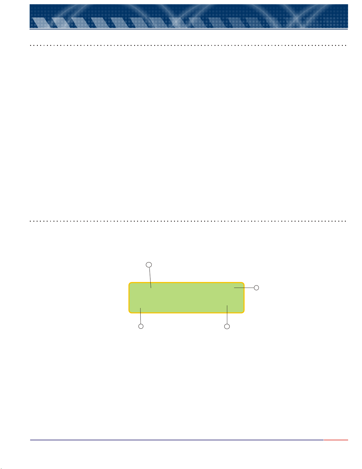
1- The "Prompt" is a signal that flashes every time a reading is performed, depending upon the time between
readings, that can be selected during Set Up Mode.
2- The measured value and the element unit.
3- Sample Temperature.
4 - Read Element.
2
11
Page 13
Certificado de Garantia
1.
9.
1) The CDCN442 equipment software, offers self-explanatory menus interacting with the user. The
dialog between the Analysis Program and the user, is achieved thru a 2x6 alphanumeric display. The
main menus and hidden options menus are displayed to the user. The hidden option menus, are
displayed using arrows where one of them will flash and in order to access the hidden options, press
<SELECT> key and to confirm the option chosen press <ENTER> key. Always use <SELECT> key in
order to change the option at the menu, then use <ENTER> key to confirm the option chosen.
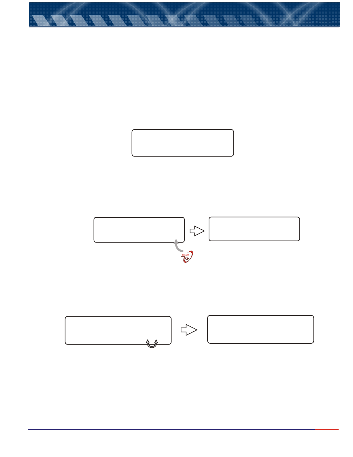
Note: at this manual the hidden options are displayed on the side of the function, as shown
below:
Equipment Operation (cont.)
SELECT OPTION
Option 1 _>
Note: at this manual the active Menus will be displayed in color.
2) If a mistake or error happens and it is necessary to change data or to return to a previous screen,
press <ESCAPE> key.
Find below an example.
SELECT OPTION
Option 2 _>
3)In certain program steps, where value adjustments are offered, the symbols “<” (decrease) and “>”
(increase), follow steps as shown below:
Blue
Say the user had selected Option 2 but
he made a mistake and wants to change to
Option 1. Press <ESCAPE> key and the screen
will move bak to prior screen.
Hidden option for
Set Up & Calibration
OPTION 2
SELECTED
CALIBRAT. POINT
10.0 mg/L <>
Press <SELECT> key in order to
alternate betwen options decrease (<)
or increase ( ) from the value
displayed, then confirm by pressing
<ENTER> key.
4) The equipment stores the configuration on a non-voltile memory (E PROM). Even when turned off,
the last working conditions will be sustained.
>
CALIBRAT. POINT
11.0 mg/L <>
Press <SELECT> key alter the value.
When reached the desired value,
press <ENTER> key accept the value
and move to next step.
2
12
Page 14
9.
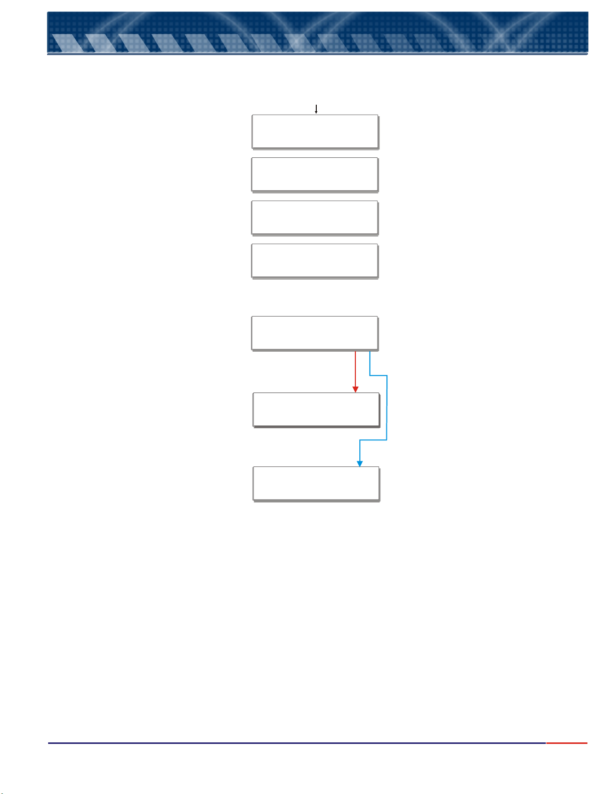
When powering the equipment, the display will show the model and software version then the aplication
where the equipment was last being used at the process.Finally the Process Reading will be displyed.
Equipment Operation (cont.)
Main Menu
Analyzer
CDCN442 V.1.0
Equipment Model and Software
Version will be displayed.
Read:
The Element chosen during Set Up.
Ex. NaOH, range 0 thru 100 g/L.
NaOH 0-100g/L
NaOH 25ºC
-> 10.0 g/L
SELECT
Read _>
The read value obtained for NaOH
from the sample, just after being
powered (instantaneous read).
Press <ENTER> key to go to Stand By,
press again to go back to Reading Mode...
Press and hold <Escape> key in order
to move back to the Main Menu where
the arrows indicate hidden options
SELECT
Read _>
SELECIONE
SELECT
Setagem _>
Set Up _>
Or
Press <SELECT> key, in order to
access the Set Up or Calibration option
(hidden options). Confirm the chosen
option by pressing <ENTER> key.
Select Set Up option, press <ENTER>
key then follow the flow diagrham from
item 9.1 on page 14.
SELECT
Calibration ->
Select the Calibration option, then follow
the flow from item 9.2 on page 16.
13
Page 15
Operação do equipamento - Setagem
10.
9.1
Equipment Operation - Concentration Set Up
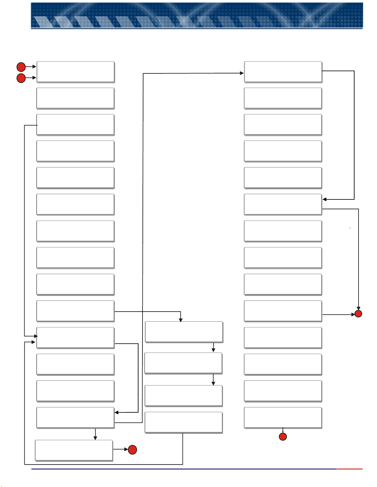
Cocentration Set Up Menu: allows user to prepare the equipment for process concentration analysis, as
desired by the user.
A
D
From page 15
SELECT
Set Up _>
SELECT
_> Portuguese
Hidden Options
English or Spanish
Configure
S
R 485? _>Yes
Bits per Second
_>9600
Hidden Option
No
Hidden Option
1200
2400
4800
19200
Hidden Option
No
Configure
Analyzer? _>Yes
FUNCTION
_>Concentrat.
UNIT
_> g/L
SELECT
NaOH 0-15 g/L_>
CALIBRATION
_>Manual
Calibrate in?
_>Concentrat.
Calibration Pt.
100g/L <>
New Cell?
_> No
Configure
Output: _>Yes
Data Bits
_>8
Hidden Option
Conductivity
Parity
_>Even
Eqpto.Network
Hidden Option
%
Consult Page 10
for a list of
Elements
Number: 1 <>
Configure
4-20mA? _>Yes
Value 4mA
Hidden Option
Auto
0g/L <>
Value 20mA
Hidden Option
Conductivity
Using the arrows
< or > to adjust
Calibration Point.
.Confirm pressing
<ENTER> key. See
page 12.
Hidden Option
Yes
150g/L <>
Burnout 4-20mA
20mA _>
Adjust
4-20mA ? _> Yes
Thermostatize
Hidden Option
No
Adjust values.
See page 12
Place Ampmeter
@ 4-20mA Output
Hidden Option
7
Hidden Option
Odd
Using the arrows
< or > adjust
the equipment#
within the network.
Confirm pressing
<ENTER> key.
Using the arrows
< or > adjust the value
for 4 mA and 20 mA.
See page 12
Hidden Option
4 mA
Last Value
Hidden Option
No
Go to Page 15
Connect an Ampmeter
to contacts 9 & 10 from
Cn2.
B
Reading Mode
_>Continuous Ready?
Time bwetween
Read 1s. <>
Config.
Transmis.? _>Yes
Hidden Option
No
WAIT
...............
Hidden Option
Average
Using the arrows
< or > adjustar
Calibration Point.
.Confirm pressing
<ENTER> key.
See page 12.
A
Thermostatize
[email protected]ºC<E>
WAIT
>>>>>>>>>>>>>>
Stabilizing
Press
<ENTER>
to continue
Adjust : 4mA
<Sel> - <Esc> +
Adjust : 20mA
<Sel> - <Esc> +
C
Go to Page 15
Press <ENTER> key
Adjust the 4-20mA current
values, <SELECT> key
will decresase and
<ESCAPE> key will
increase the current
value
14
Page 16
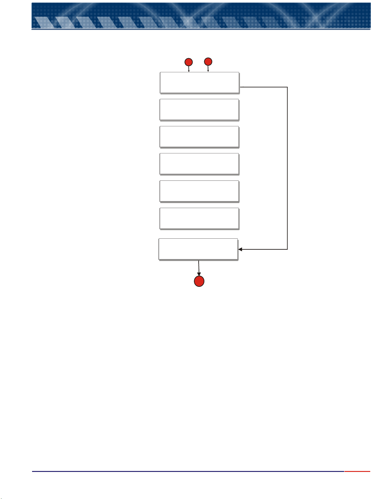
10.
9.1
Operação do equipamento - Setagem
Equipment Operation - Concentration Set Up
From page 14
B
C
Configure
Control? _>Yes
Control
On-Off _>
Set-Point
100g/L <>
Acting
Direct _>
Hystereses
0g/L <>
Burnout Control
Open _>
From page 14
Hidden Option
No
Hidden Option
PWM
Adjust Set-Point, using arrows
< or >. See page 12.
Hidden Option
Reverse
Adjust Hystereses, using
arrows < or >. See page 12..
Hidden Option
Last Value
Closed
WAIT
................
D
Go to page 14
15
Page 17
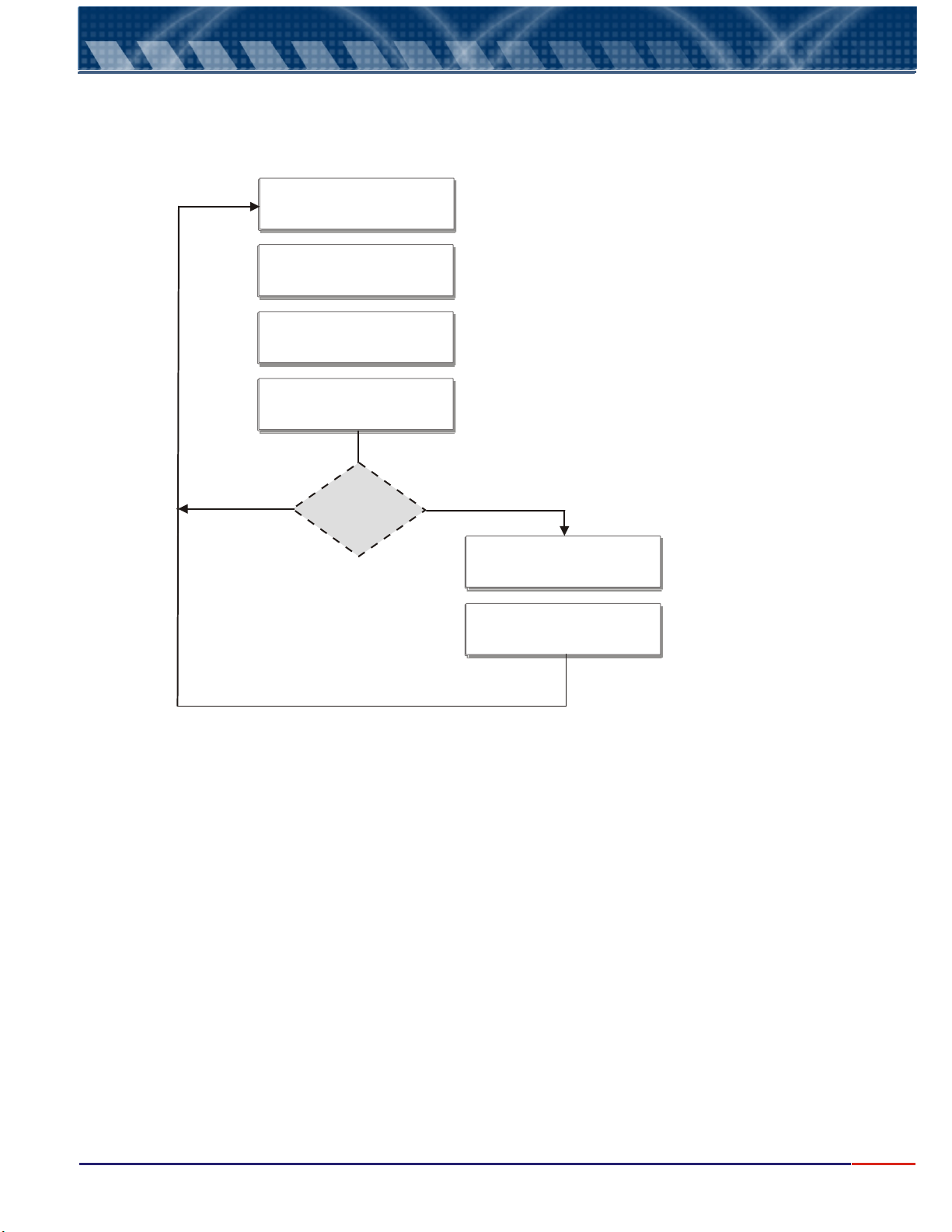
10.
9.2
Operação do equipamento - Setagem
Equipment Operation - Concentr. Calibration
SELECT
_>Calibration
Place Cell @
Yes
100g/L
NaOH
Ready?
CALIBRATING
Cell is
OK?
Choose Calibration, then,
press <ENTER> key.
Follow screen instructions.
Press
<ENTER> key
No
Attention!!!
Verify Cell
Verify Standard
<ENTER>
Verify Cell physical
and function conditions.
Verify the Standard
conditions being used!
If good, press <ENTER>
16
Page 18
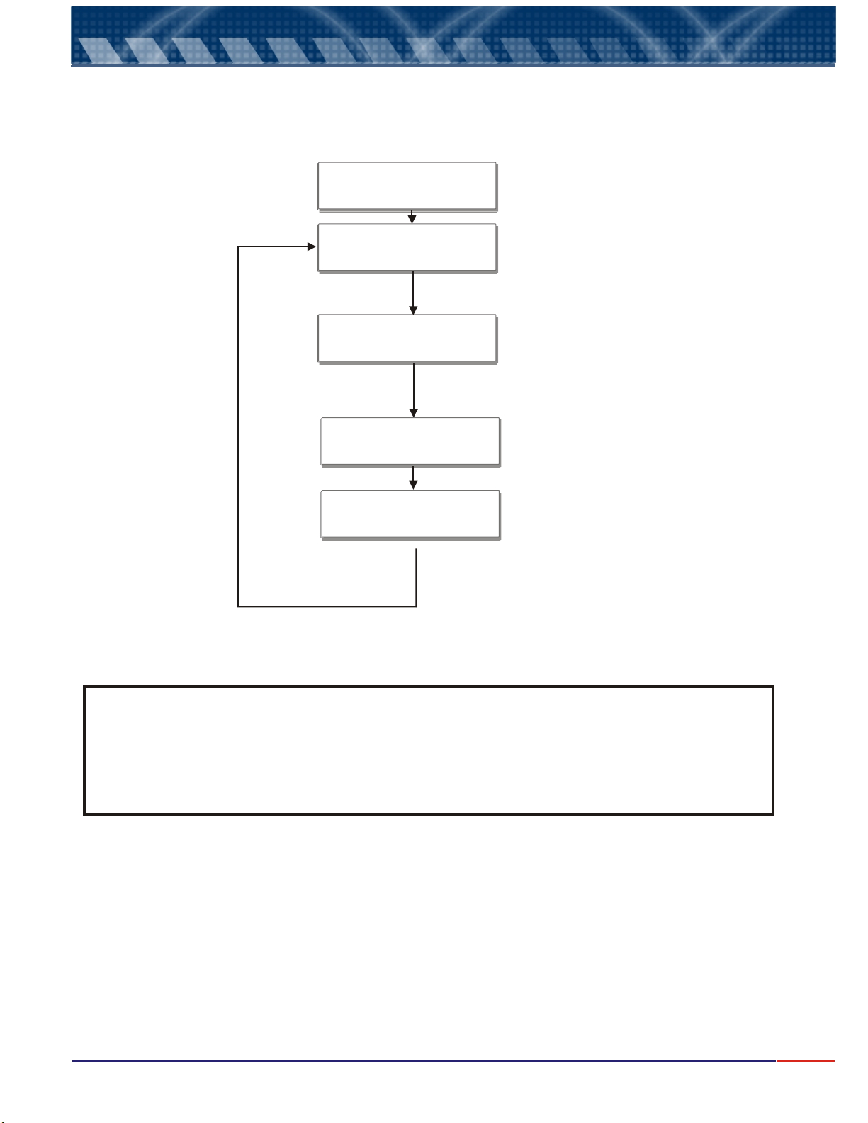
10.
9.3
Operação do equipamento - Setagem
Equipment Operation - Concentration Read
SELECT
_>Read
NaOH 25ºC
-> 10.0 g/L
Press
<SELECT> key
18.50 mA
25ºC
-> 908.1 mS/cm
10.0 g/L <>
Press
<SELECT> key
Read Value
Current Value refering
to read will be displayed.
Press
<SELECT> key
Conductivity Value
will be displayed
Press
<SELECT> key
If during Set Up Manual Calibration was chosen,
Press <Select> key in order to adjust the value
read..
NOTE: during read Mode, pressing and holding <ESCAPE> key will instruct the program analysis to
exit the mode, moving back to the Main Menu. This action will not halt the Reading Operation
while user performs another operation, reading will still be performed by the instrument.
If user desires to halt Reading Operation, first place the instrument in Stand-By pressing
<ENTER> key, then press and hold <ESCAPE> key to exit reading and access other program
area.
17
Page 19
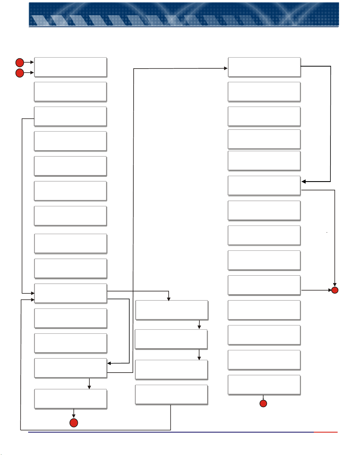
Operação do equipamento - Setagem
10.
9.4
Equipment Operation - Conductivity Set Up
Conductivity Set Up Menu: allows user to prepare the equipment for process conductivity analysis, as
desired by the user.
A
D
From page 19
Hidden Option
No
SELECT
Set Up _>
SELECT
_> Portuguese
Configure
Analyser? _>Yes
FUNCTION
_>Conductivity
RANGE
RESOLUTION
0.1 _>
CALIBRATION
_>Manual
Calibration Pt.
111.9 mS/cm <>
New Cell?
_> No
Configure
Display: _>Yes
Reading Mode
_>Continuous
Configure
RS485? _>Yes
Bits per Second
Hidden Options
English or Spanish
_>9600
Data Bits
_>8
Hidden Option
Concentration
Parity
_>Even
Eqpto.Network
Press
5 - 2000 mS/Cm
<ENTER>
Number: 1 <>
Configure
4 - 20mA? _>Yes
Hidden Option
1
Value 4mA
Hidden Option
Auto
Using the arrows
< or > to adjust
Calibration Point.
.Confirm pressing
<ENTER> key.
See page 12.
10.0mS/cm <>
Value 20mA
10.0mS/cm <>
Burnout 4 - 20mA
Hidden Option
Yes
Hidden Option
No
Hidden Option
Average
Thermostatize
Cell:25.0ºC<>
Adjust value.
See page 12
20mA _>
Adjust
4 - 20mA ? > Yes_
Place Ampmeter
@ Output 4-20mA
Hidden Option
No
Hidden Option
1200
2400
4800
19200
Hidden Option
7
Hidden Option
Odd
Using the arrows
< or > adjust
the equipment#
within the network.
Confirm pressing
<ENTER> key.
Hidden Option
No
Using the arrows
< or > adjust the value
for 4 mA and 20 mA.
See page 12
Hidden Option
4 mA
Last Value
Hidden Option
No
Go to Page 19
Connect an Ampmeter
to contacts 9 & 10 from
Cn2.
B
Reading Time
1s <>
Configure
Transmis.? _>Yes
Hidden Option
No
WAIT
...............
A
Using the arrows
< or > to adjust
Calibration Point.
.Confirm pressing
<ENTER> key.
See page 12.
Thermostatize
Cell:25.0ºC<E>
WAIT
>>>>>>>>>>>>>>
Stabilizing
Press
<ENTER>
Ready?
Adjust : 4mA
<Sel> - <Esc> +
Adjust : 20mA
<Sel> - <Esc> +
C
Go to Page 19
Press <ENTER> key
Adjust the 4-20mA current
values, <SELECT> key
will decresase and
<ESCAPE> key will
increase the current
value
18
Page 20
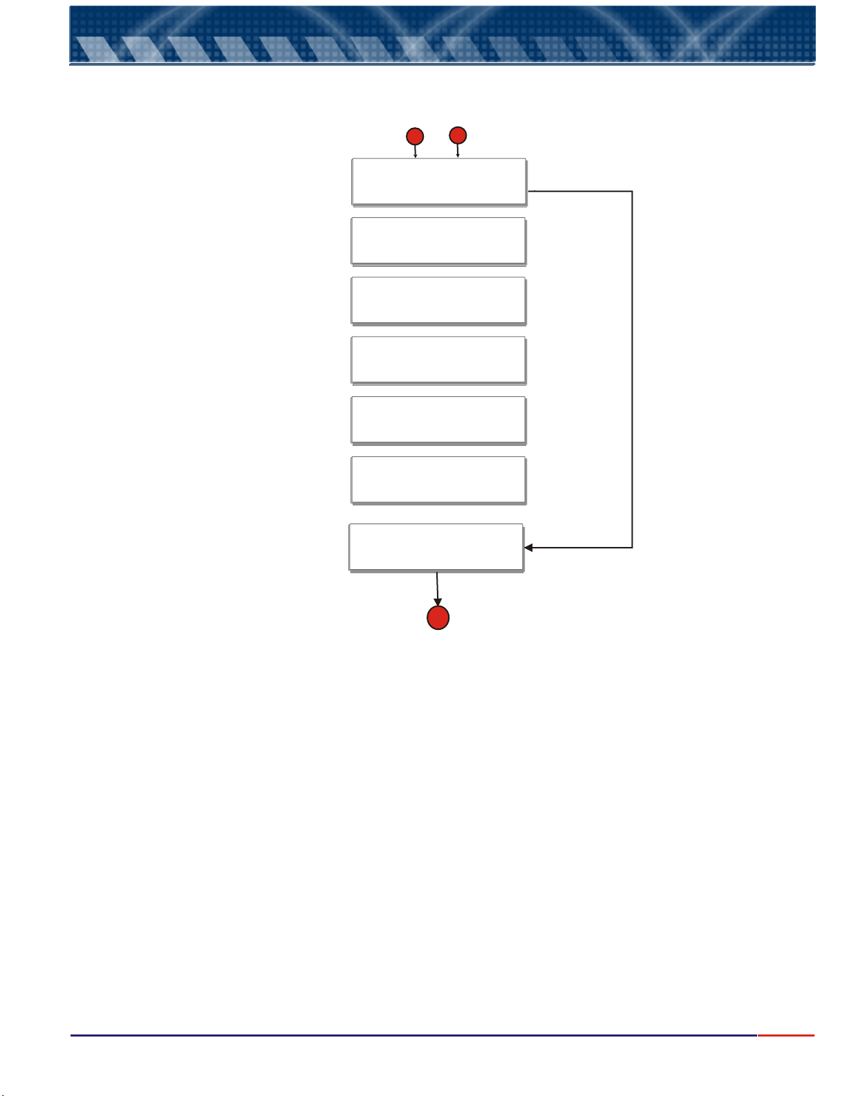
10.
9.4
Operação do equipamento - Setagem
Equipment Operation - Conductivity Set Up
From Page 18
B
C
Configure
Control? _>Yes
Control
On-Off _>
Set-Point
10.0 mS/cm <>
Acting
Direct _>
Hystereses
0.0 mS/cm <>
Burnout Control
Open _>
From Page 18
Hidden Option
No
Hidden Option
PWM
Adjust Set-Point, using arrows
< or >. See page 12.
Hidden Option
Reverse
Adjust Hystereses, using
arrows < or >. See page 12..
Hidden Option
Last Value
Closed
WAIT
................
D
Go to page 18
19
Page 21
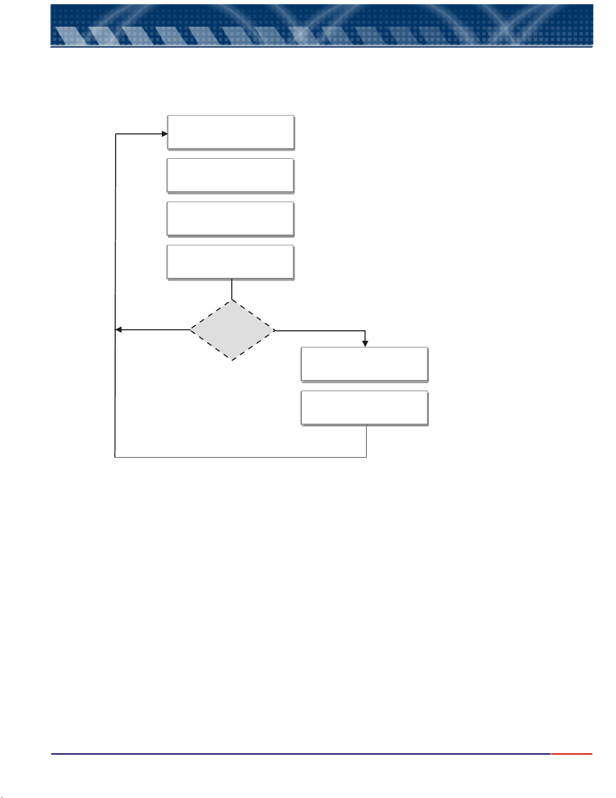
10.
9.5
Operação do equipamento - Setagem
Equipment Operation - Conduct. Calibration
SELECT
_>Calibration
Place Cell @
Yes
111.9 mS/cm
Ready?
CALIBRATING
Cell is
OK?
Choose Calibration, then,
press <ENTER> key.
Follow screen instructions.
Press
<ENTER> key
No
Attention!!!
Verify Cell
Verify Standard
<ENTER>
Verify Cell physical
and function conditions.
Verify the Standard
conditions being used!
If good, press <ENTER>
20
Page 22
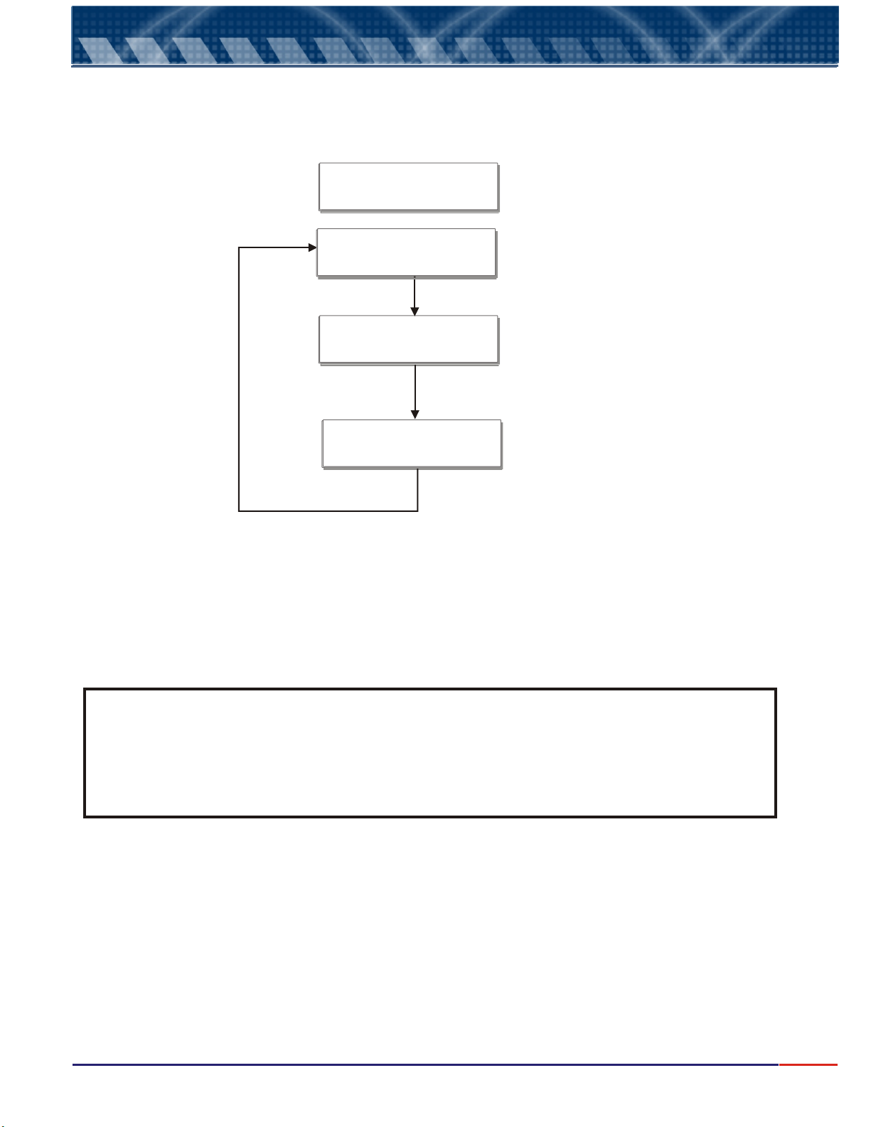
10.
9.6
Operação do equipamento - Setagem
Equipment Operation - Conductivity Read
SELECT
_>Read
25ºC
-> 908.1 mS/cm
18.50 mA
908.1 mS/cm <>
Press
<SELECT> key
NOTE: during read Mode, pressing and holding <ESCAPE> key will instruct the program analysis to
exit the mode, moving back to the Main Menu
If <ENTER> key is pressed, the equipment will go to Stand -by Mode.
Read Value
Press
<SELECT> key
Current Value refering
to read will be displayed.
Press
<SELECT> key
If during Set Up Manual Calibration was chosen,
Press <Select> key in order to adjust the value
read..
NOTE: during read Mode, pressing and holding <ESCAPE> key will instruct the program analysis to
exit the mode, moving back to the Main Menu. This action will not halt the Reading Operation
while user performs another operation, reading will still be performed by the instrument.
If user desires to halt Reading Operation, first place the instrument in Stand-By pressing
<ENTER> key, then press and hold <ESCAPE> key to exit reading and access other program
area.
21
Page 23

Operação do equipamento - Setagem
10.
10
It is recommended a visual inspection of the cell periodically and if noticed the cell is dirty, please wash
it using neutral detergent and wash it throughly.
After the cleaning please proceed with the cell calibration.
Cell Maintenance
22
Page 24

11.
1) Proprietary:
Order:
ESC ID P CR LF
0x1B 0x50 0x0D 0x0A Hexadecimal
Answer:
L > > V V V V V V mS C C C C C C m A
Example of answer for an un-stable value
L > 20 mS 1 2 . 0 0 m A
Example of answer for a stable value
Communication Protocol
The ID is configured at the instrument from 1 to 32.
L > > 20 mS 1 2 . 0 0 m A
Note: a) When the answer comes a C instead of a L, it means that the equipment is under
calibration function (is being operated in location by the user, executing the calibration
operation at the instrument).
b) When the answer comes an S instead of a L, it means that the equipment is under Set Up
function and it is being operated in location by the user.
2) RS485 – It is a “physical location”, where the proprietary protocol will be “transported”.
As factory default, this communication comes configured as:
Speed = 9600
Parity = none
Number of Bits = 8
Stop Bit = 1
ID = 1
23
Page 25

12.
Symptom Verify Action
Equipmento does not power on
Electrical Power
General Fuse F1
If power is present at Pins 1 &
2 from CN2 connector
Verify the circuit breaker;
Replace fuse;
Verify terminal barr,
Connector & Power Cable
Set- Point does not operate or
fails
Set Up – verify if Set Point 1
was selected.
Contacts 4 & 5 from CN2
Fuse F2 ( Set-Point )
Enable Set Point 1 thru the
Set Up Menu;
Verify if wires for Set – Point,
Are properly connected;
Replace Set Point Fuse.
Output Current 4–20mA,
does not operate.
Set Up – verify if 4-20mA
values were adjusted.
Enable and adjust 4-20mA
values thru Set Up Menu.
Equipment does not calibrate
Valid Standard Solution;
Standard Solution Fungus;
Set Up is correctly
programmed.
Use a new Standard Solution.
Use a new Standard Solution.
Re-do Set Up procedure.
Equipment does not read
correctly
Keyboard does not function
properly
Calibrated with a wrong
Standard Solution value;
If cell is damaged;
Cell cable damaged.
Replace keyboard;
Re-do calibration using a new
Standard Solution.
Replace Cell.
Replace Cable.
Serial port does operate if Serial port is on. Enable RS-485 thru the Set Up
menu.
Troubleshooting
R 485S
24
Page 26

Symptom
Verify Action
Electrical Power Verify the circuit breaker
Equipment does not
power on
If Pins1&2 from the terminal
barr are powered
General Fuse F1
Verify the equipment
connectors and power cable
Standard Solution Expiration
Date
Use a new Standard Solution
Fungus presence at Standard
Solution
Use a new Standard Solution
Suspicious Calibration
If the Set Up operation was
performed correctly
Re-do Set Up operation
Equipment does not
allow new calibrations
If the Standard Solution value
is compatible with the
calibration curve values
Replace Standard Solutions.
Contact Customer Service.
If the keyboard is working
properly
Replace keyboard
Equipment does not read
correctly
Damaged cell, broken or
damaged cable
Replace Cell
Serial Port not working
properly
If Serial Port is on Access the Set Up Menu and
verify if RS-485 is enabled
12.
Troubleshooting (cont.)
R 485S
25
Page 27
Page 28

M-4516/0209
 Loading...