

Page 1
OMEGA
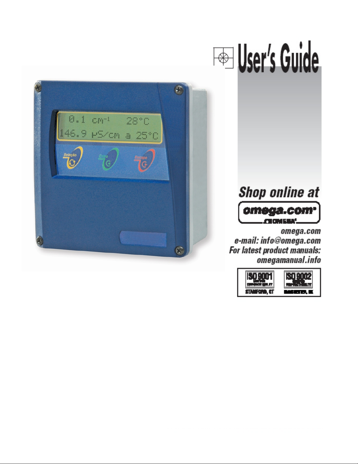
CDCN441
CDCN441
Conductivity Analyzer
Page 2

Page 3
Instruction Manual
Conductivity Analyzer
CDCN441
Index
Specifications..........................................................3
Mechanical Description ..................................................4
Dimensional...........................................................5
Typical Installation ......................................................6
Equipment Installation ...................................................7
Electrical Schematic.....................................................8
Equipment Operation....................................................9
Equipment Operation - Turning On.........................................11
Equipment Operation Conductivity - Set Up. . . . . . . . . . . . . . . . . . . . . . . . . . . . . . . . . . 12
Equipment Operation Conductivity - Calibration. . . . . . . . . . . . . . . . . . . . . . . . . . . . . . . 17
Equipment Operation Conductivity - Read...................................18
Equipment Operation Conductivity - Check . . . . . . . . . . . . . . . . . . . . . . . . . . . . . . . . . . 19
Equipment Operation Resistivity - Set Up ...................................21
Equipment Operation Resistivity - Calibration . . . . . . . . . . . . . . . . . . . . . . . . . . . . . . . . 26
Equipment Operation Resistivity - Read.....................................27
Equipment Operation Resistivity - Check....................................28
Equipment Operation Concentration - Set Up . . . . . . . . . . . . . . . . . . . . . . . . . . . . . . . . 30
Equipment Operation Concentration - Calibration . . . . . . . . . . . . . . . . . . . . . . . . . . . . . 35
Equipment Operation Concentration - Read . . . . . . . . . . . . . . . . . . . . . . . . . . . . . . . . . 36
Equipment Operation Concentration - Check. . . . . . . . . . . . . . . . . . . . . . . . . . . . . . . . . 37
Communication Protocol ................................................39
Page 4

General
Case Material Cast Aluminum SAE 323 (Back) and ABS (Front Panel)
Finishing Electrostatic Epoxy
Electrical Connection Conexel Type Connector
Cable Inlet Cable Knockout 3/8" ( 4x )
Assembly 2" Tube, Falt Surface or Panel
Enclosure IP-67
Power Consumption 3.5 VA
Weight 1.3 kg
Electrical Power 90 to 240 VAC 50 / 60 Hz
Operating Temperature 5 to 40 ºC
Relative Humidity 20 to 80%
Analyzer
Display Alphanumeric 2 lines x 16 characters
Range Conductivity 0.01uS/cm thru 2S/cm
Range Resistivity 10 ohms x cm thru Infinity
Automatic Temperature Compensation 0 to 200 ºC
Temperature Range 0 to 200 ºC
Cell Constant 0.01 / 0.1 / 1 / 5 / 10cm
Transmiter
Output Signal
Analogic 4 to 20 mA with adjustable output range. Digital RS-485
with bilateral interaction thru software up to 36 equipments 2 km
apart (optional).
Galvanic Isolation 2000 VAC (by opto coupler)
Line Resistance 600 Ohms
Controller
Actuation Type Frequency Modulation, P+Di
Set Point 2 independent from 0 to 100% of scale
Output 2 control ON-OFF, NO (1A, 260Vac)
Auto Clean Controller ON-OFF, for Periods up to 99seconds, in intervals up to 180hours
Accessories
Supplied with equipment:
Installation hardware (2x), Instruction Manual, SS 304 Clamps with
nuts and washers
2.
Specifications
3
Page 5
3.
The equipment is offered in SAE-323 aluminum case with lower oxidation level, anti corrosion
treatment and electrostatic epoxy paint finishing and frontal panel in ABS. Built in small and light
size, complying with IP-68 Standard.
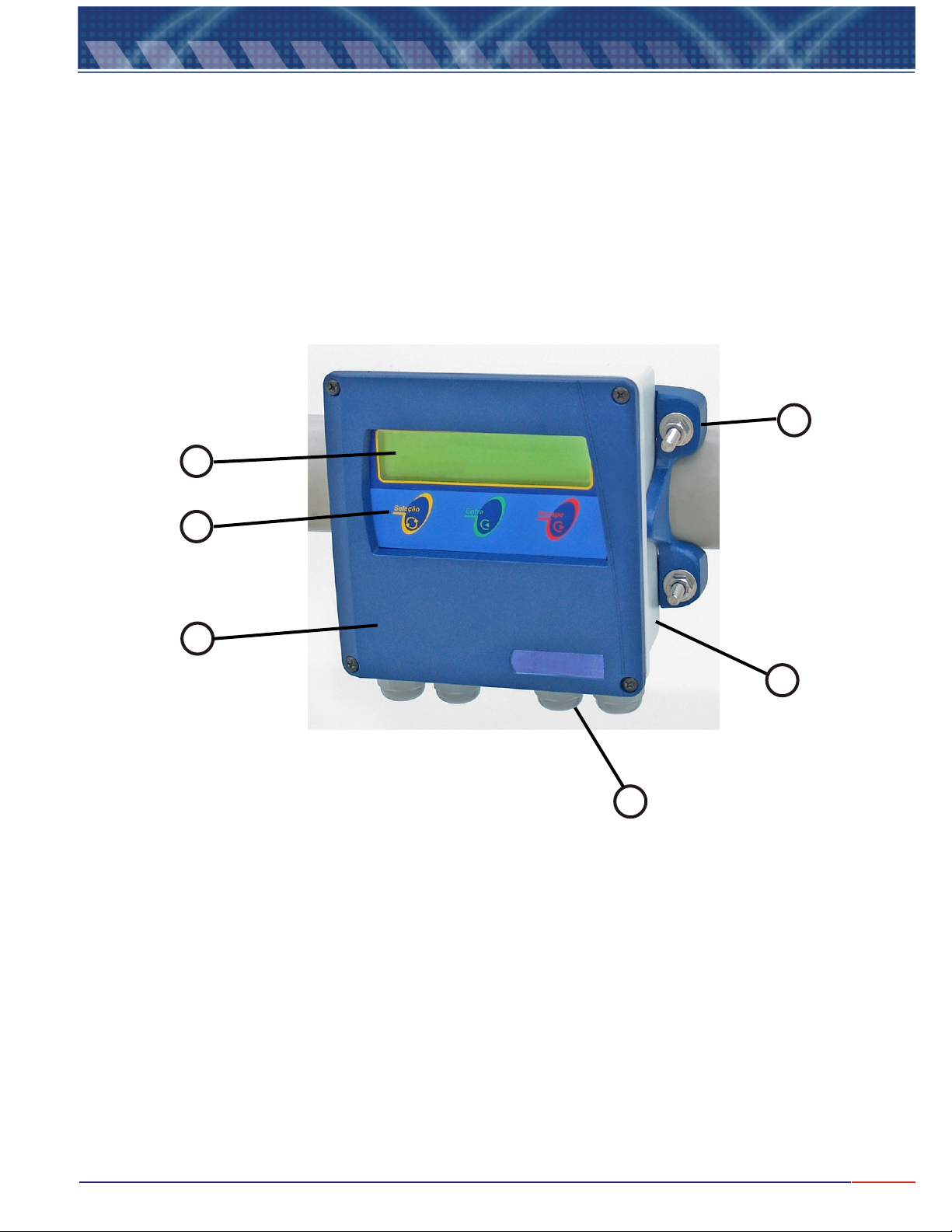
Under the same case you will find: Local Indicator, Analyzer, Transmitter and Controller.
The mounting of the instrument can be done on 2” Tube" or in Flat Surface or Wall Mounting.
The electrical connection is possible thru a terminal block located internally at the lower portion of
The case and the cable knockouts are located in the bottom of the case, 4x 3/8".
Mechanical Description
6
2
3
1
OMEGA
CDCN441
4
1 - Frontal panel in ABS.
2 - Display alphanumeric 2 lines x 16 characters.
3 - 3 keys Tactile Membrane Keyboard:
<SELECT>
= Select the desired operation, flashing option.
<ENTER>
= Enter the program commands for analysis, confirm above Selected Function.
<ESCAPE>
= Move back one step at every touch or if hold for about 5 seconds to exit reading mode.
4 - Cable knockouts 4x 3/8"
5 - Aluminum Case (SAE 323).
6 - Installation Hardware for Wall Mounting, 2” tube and panel.
5
4
Page 6
4.
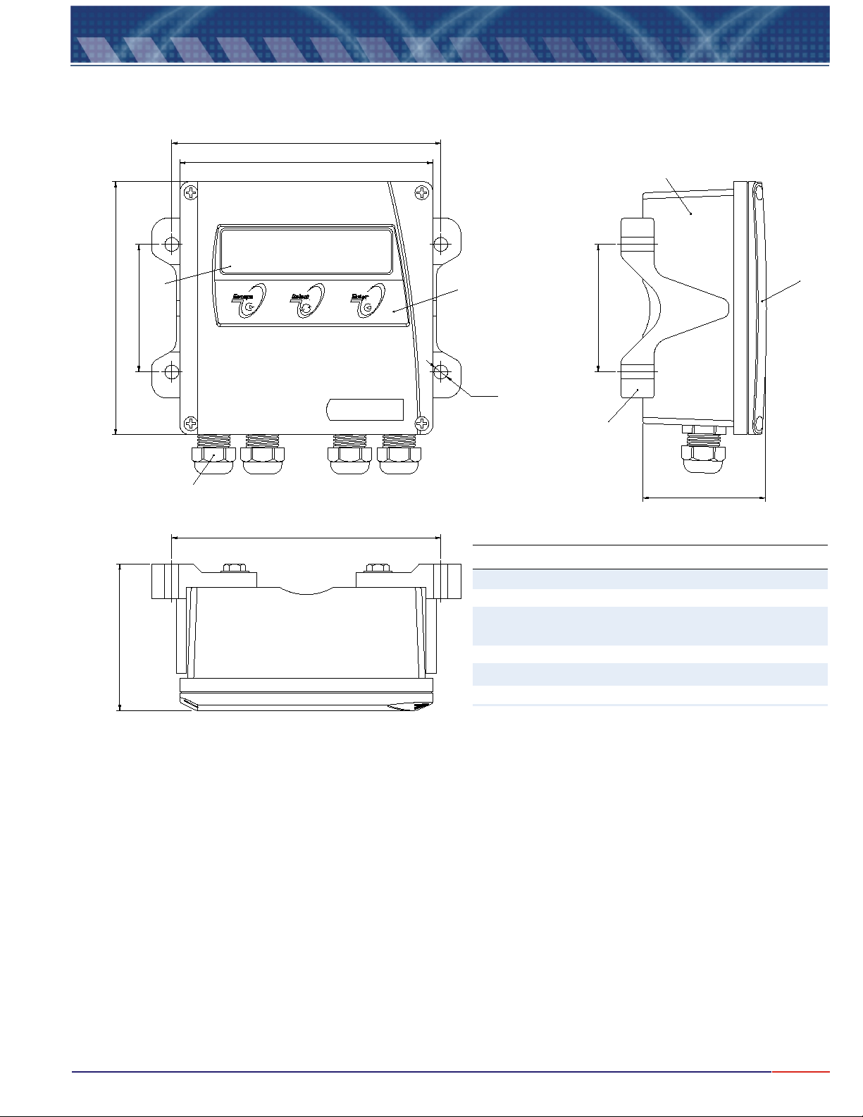
Item Description
1 Frontal Panel in ABS
2 Aluminum Case
3
Intallation Hardware for panel, Flat Surface or
2” Tube
4 Cable Knockout 3/8”
5 3 Keys Keyboard
6 Alphanumeric Display 2lines x 16characters
Dimensional
¢154
145
2
SELECT FUNCTION
56
145
¢73
Ø8(4x)
Conduc. Analyzer
CDCN441
4
¢154
84
¢73
3
70
1
Note: Dimensions in millimeters
5
Page 7
5.
Typical Installation
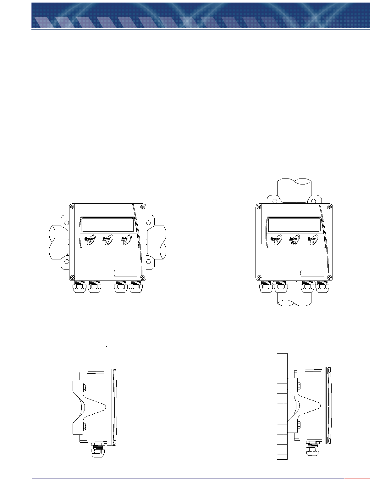
The CDCN-44I can be installed in 3 different ways: Panel, 2” Tube and Flat Surface.
For installation purpose the instrument is offered with the following hardware: 2 Installation Support, 4
SS screws ¼" x ½", 4 SS washers ¼", 2 "U" SS clamps , 2 SS nuts and 2 SS washers ¼".
These hardware allow 3 different ways for installation, to know:
a) Installation in 2” tube: Uses 2 installation support + 2 "U" clamps with nuts and washers.
b) Installation in Panel: Uses 2 installation support ; the edges will be placed against the internal
surface of the panel, 4 screws. ¼" x ½” will be used to hold it in place.
c) Installation in Flat Surface(Wall Mount): Uses 2 installation support and “U” clamps holes are also
used to hold the instrument in place at flat surface.
2" TUBE
INSTALLATION
SELECT FUNCTION SELECT FUNCTION
Conduct Analyzer
CDCN441 CDCN441
POSITION A
POSITION B
PANEL
INSTALLATION
FLAT SURFACE
INSTALLATION
Conduc Analyzer
6
Page 8
6.
Electrical Installation
1- Remove the equipment from the box and verify for any possible damage caused during
transportation;
2- Install the equipment at an strategic place, allowing easy access, exempt of vibration and vapors,
follow the information supplied on page 6 (Typical Installation);
3- Avoid exposing the equipment direct to solar rays; and if necessary supply protection to the case;
4- Verify if the electrical installation is correct, and if security circuit breakers are installed and if
grounding is performed correctly;
5- Proceed with the equipment installation.
Electrical Installation
1- Remove the frontal lid of the equipment;
2- Insert the cables thru the cable knockouts, certifying that the connections are correct, verifying the
identifications drawing and the electrical schematics;
3- The cables must be firmly attached to the cable knockout, avoiding humidity from being created
inside the equipment and preserving IP 67 enclosure;.
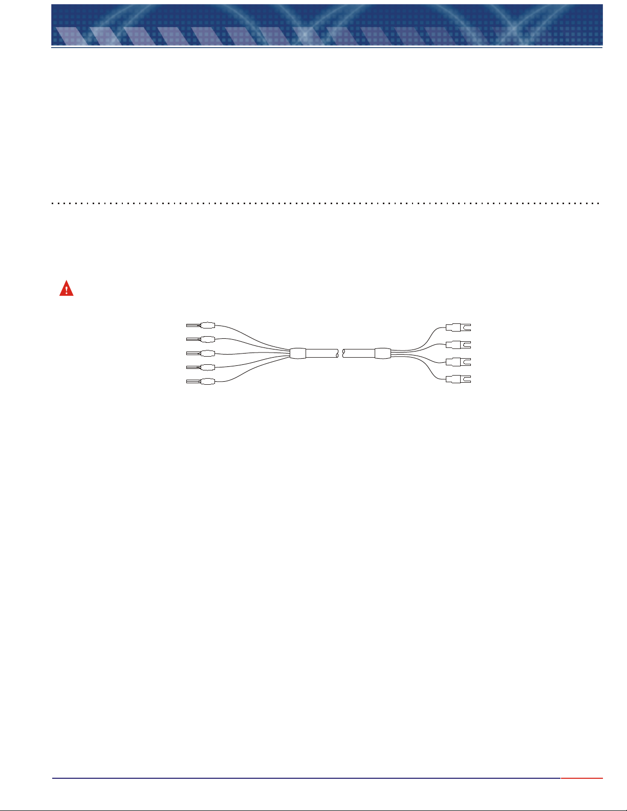
Never cut or mend the probe cables, as reading errors could occur.
(Shield)
(Green)
(Yellow)
(Red)
(Black)
12
13
14
15
16
Equipment Side
INTERCONNECTION CABLE
Cell Side
4
3
2
1
(Green)
(Yellow)
(Red)
(Black)
(Note: above cable is not supplied with the Analyzer, only with cell!)
7
Page 9
7.
Electrical Schematic
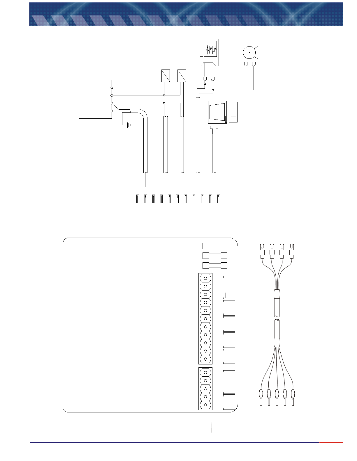
Note: it is important to use independent
L
C
IA
T
E
LCR
E
phases and cables for
O
T
U I N
I
T
IS RB
D
equipments and control or
GRAPHIC
REGISTER or
CONTROL
or
CONTROL
or ALARM
or AUTO CLEAN
T N
OX
S
B
alarm valves.
1
R
2
3
GROUNDING
CABLE 3
1
4
CABLE 4
2
3
4
ALARM
5
7
6
CABLE 5
CABLE 6
CABLE 7
5
6
7
8
9
10
PLC ro SDLC
PC
CONVERTER
RS-485 / RS-232
11
PUMP
(Green)
(Yellow)
(Red)
4
3
F3
F2F1
AC
2 1
3
No
4
SP2
C
5
CN2
CDCN441
MAIN BOARD
ion
ect
n
onn
c
ctio
ne
ermo
h
T
ll con
-
Ce
n
ee
r
G
Red
&
&
ck
Bla
Yellow
CN1
oN
SP1
C
7
8 6
+
mA
-
910
+
RS-485
-
11
S
hie
.
12
G .
r
e
13
.
l
e
Y
14
edR
1516
Bl
ac
k
ld
end;
g
T = Black
Le
P
n
ree
ed
R
G
= Shie
=
M
V
.
=
D
AM = Yellow
V
Blind
INTERCONNECTION CABLE
13
12
(Shield)
(Green)
(Black)
2
1
Cell Side
Equipment Side
14
15
16
(Red)
(Black)
(Yellow)
Note: this cable is not supplied with the instrument, only with the cell!
8
Page 10
8.
Equipment Installation
Set Up Operation
The menus are self explanatory with its respective options, that are selected by press key. When the
selected option flashes, press key to confirm the selected option.
If a mistake is made, press key to go back (one step at every touch) and modify the option, except while
during Reading Mode, when key needs to be held for about 5seconds in order to exit this mode.
The equipment offers a non-volatil memory (E2PROM), in order to store operations functions (resolution,
reading, Calibration and more). Even when turned off from power, all functions chosen during set up will remain
stored.
Before starting any work with the equipment, it is recommended to to certify
that you have chosen the correct options for the operation .
When at the , press key in order to select the desired function, flashing
option, then press , press key until SET function flashes, then
press . A Password will be requested, press in sequence ,
<ENT>
flashing option, press key until the desired option flashes then press
In order to move to the next screen, user must press .
FUNCTION SELECT
<ENT>
<ENT>
, then follow step by step the options shown at the screen. In case the user desires to change the
key to confirm the option chosen
<ESC>
<SEL>
<ENT>
<ESC>
<ESC>
menu
key. In order to access the
<SEL>
SET UP
<ENT>
key
verify the SET UP parameters,
<SEL>
<ENT>
<SEL>
<SEL>
key to confirm the option.
Check Operation
The option Cell Check is very useful, as it allows the user to verify the cell condition. This option is self
explanatory, just press key until Check option flashes, then press . Then follow
The display instructions as it is self explanatory.
<SEL> <ENT> key to confirm it
Read Operation
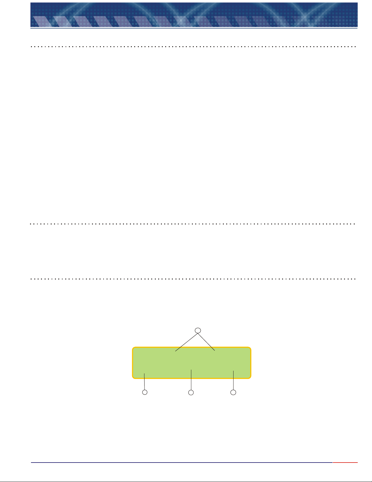
At this operation user will have options to and . In case the desire is to
Cell option flashes, then press key to confirm the option chosen
, press key until . From
this point on the program will guide the user step by step on how to proceed with the perfect calibration. In case
the desire is to Read, press key until option key to confirm, then the
Display show the following form:
<SEL>
<ENT>
Cal
<SEL>
CALIBRATE READ CALIBRATE
Read
flashes, then press
4
<ENT>
the
»»» »»»
-> »»»»»»» @ »»»»
1
1- The "Prompt" is a signal that flashes every time a reading is performed, depending upon the time between
readings, that can be selected during Set Up Mode.
2- The measured value (Conductivity or Resistivity).
3- The Reference Temperature (chosen during Set Up Mode).
4- - Set Points 1 & 2 conditions.
2
3
9
Page 11

8.
Equipment Installation (cont.)
Important Information
1- While at , user can obtain other information: by pressing , it is possible to obtain
Temperature or Set-Points values. Pressing , will place the equipment in While in
STAND BY
are NO (Normally Open). The outputs must be programmed by the user.
<ESC>
2- key will only be recognized if pressed for a longer period of time (about 5 seconds), while at
Reading Mode. This time is necessary in order for the equipment to certify that the user really wants to exit the
Reading Mode.
3- In the event of a power failure, the equipment will retain initial set up as prior of being turned off, when the
power returns, the outputs and the display will return to activities prior of being turned off.
4- Every time the cell is replaced by a new one, it is necessary to match the thermo compensator value with
the instrument and in order to do so, place tap water into a beaker then using a thermometer, measure the
Temperature of the tap water (C).
Access SET UP Mode and when prompted with question “NEW CELL?” choose YES, then confirm by
choosing YES again, then adjust the temperature shown at the display in order to match the temperature of the
water at the beaker, then press Enter and wait until finished.
When the instrument is shipped from factory with the instrument, the cell had been previously thermostatized
and no further procedure is necessary!
Reading
<ENT>
the outputs will be turned off, that means, the output current will be altered to 4 mA and the contacts
key Mode.
<SEL> key
STAND BY
10
Page 12
9.
Equipment Operation - Turning On
Basic Operation
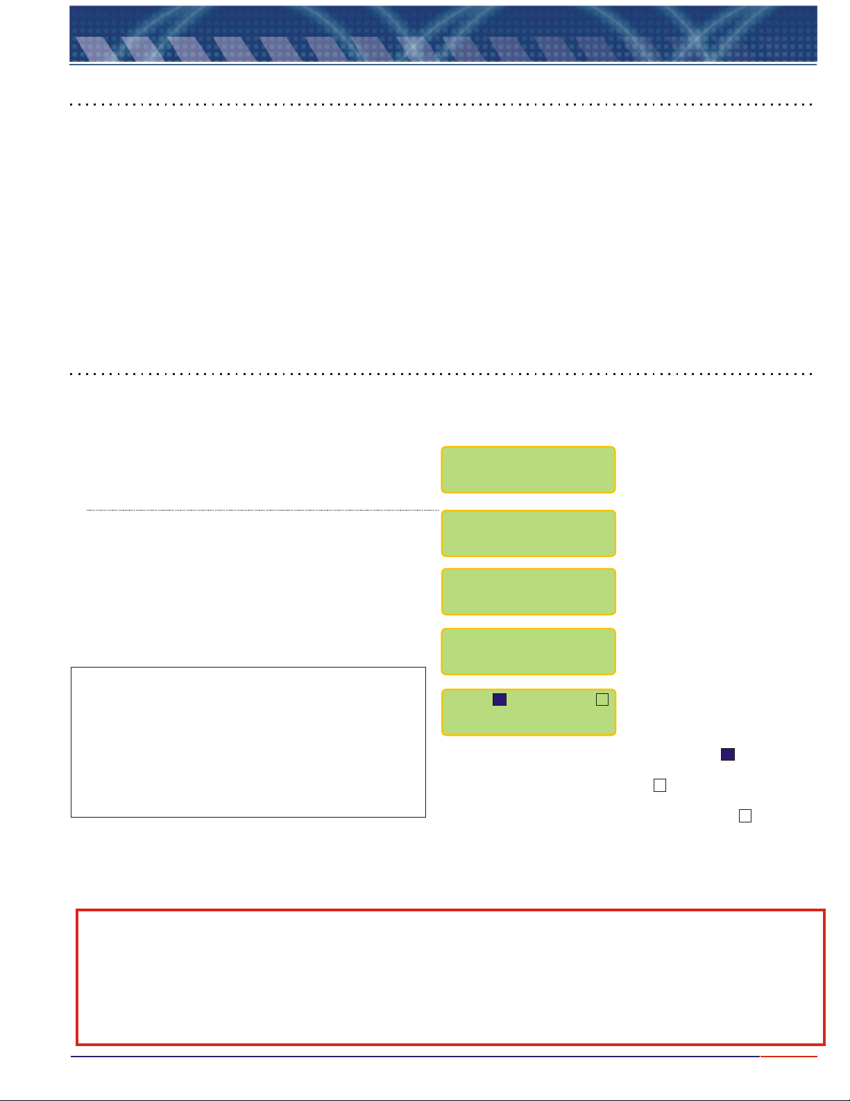
1 - The Software offers self-explanatory menus interacting with the user. The active menu is shown like and
Flashing option. Press
<ENTER>
ey to confirm it.
k
<SELECT>
key in order to move around and pick the desired flashing option, then press
2 - In case of an error, to modify the data or to go back to a prior menu, press .
3 -The equipment stores every configuration in a non-volatile memory (E PROM). Even when turned off, the last
working conditions will be sustained.
4- This instrument works for Temperature compensation NTC (Negative Temperature Compensation) but it can
also be supplied for Pt100, Pt1000, PTC3000 and Manual. The instruments will automatically recognize if a
Thermo Compensator is attached or not to the instrument!
<ESCAPE>
2
key
Turning On the equipment
1 - Connect the instrument to power . It will go straight to reading Mode. Below screens will be displayed!
OMEGA
MODEL:CDCN441
Performing Auto Check for memories, EPROM and
E2PROM.
Performing the Display Check
AUTO CHECK
DISPLAY TEST
..............
(***)Press and Hold if user desires to exist the Reading
Mode and access the Main Menu (page 12). This action will not halt
Reading operation of the instrument, while the user performs
another operation.
If the user desires to Halt the operation, first place the instrument
in Stand By Mode by pressing key, then press and hold
<ESC>
key to exit reading mode and access the Select Function.
Note A: Every time you see the symbols “ ” “ ”, that means that the user can adjust the displayed value up or
down.
To increase the value pres key until “ ” flashes, then press to confirm, then press key and at
every touch the value will increase by one unit.
To decrease the value press key until “ ” flashes, then press to confirm, then press key and at
every touch the value will decrease by one unit.
If a mistake is made, press key to return and correct the value!
<ESC>
S1: S2:
X
7.00 pH @ 25 ºC
Interpreting the Read menu. For S1, the indicates
<ENT>
>
and <
<SEL> <SEL>
<SEL> <SEL>
<ESC>
>
<
that this contact was set as On during Set Up and it
is now operating. For S2, the indicates that this
contact was set as On during Set Up but it is not
operating now and it can also be shown as if the
Contact was set to Off during Set Up.
<ENT>
<ENT>
X
11
Page 13
9.1
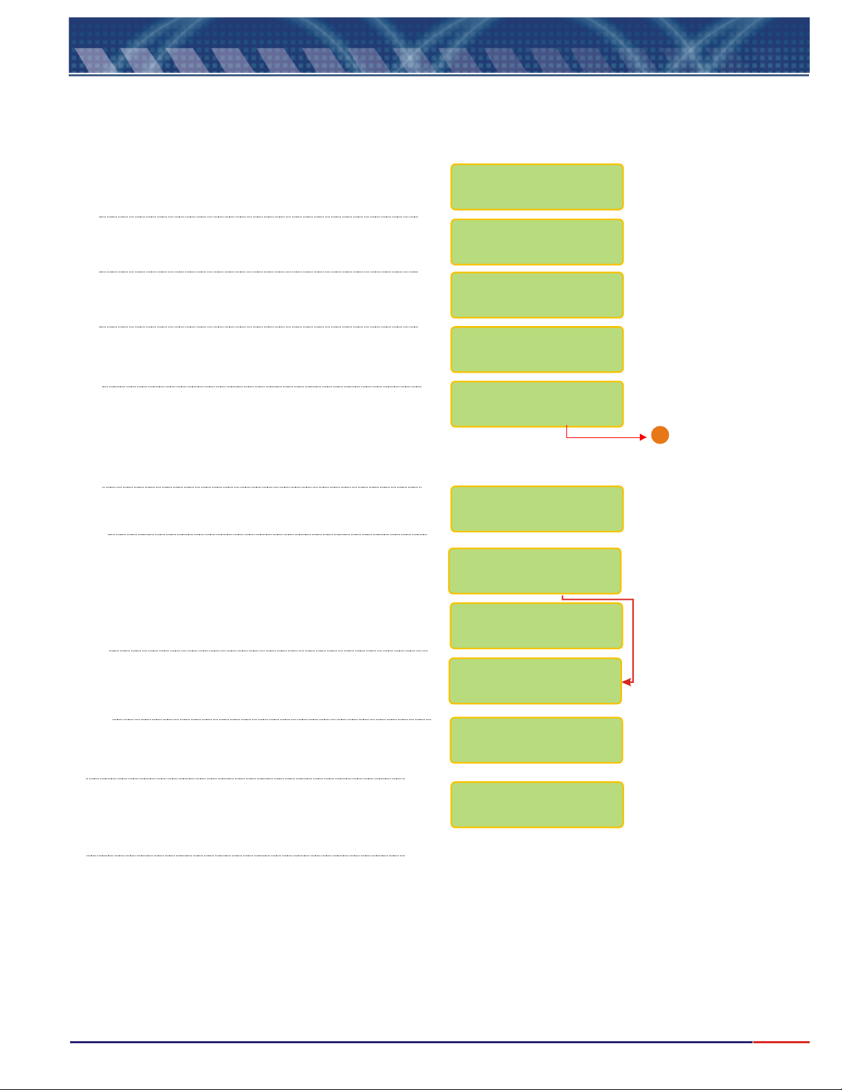
At the beginning of every operation, verify the Set Up conditions of the equipment and certify the parameters are correct
for your application.
Press option
flashes, then press key to confirm.
Equipment Operation - Conductivity - Set Up
<SEL> key until Conductivity
<ENT>
Press until flashes then press
<SEL> Set Up
<ENT>
key.
SELECT FUNCTION
/RES./CONC.COND.
COND. : /
READ
/ CHECK
A Password is required in order to access the .
Press in sequence , and keys.
In order to select the desired language, press
<SEL>
press key to confirm.
User can program the instrument, such as Electrode
type, Resolution and more. If chosen , the last
configuration will remain in effect. Press key
until the desired option flashes, then press
key to confirm.
You can calibrate the instrument as factory default.
Choose and confirm and the instrument will
calibrate as factory default! This option is offered in case
the user does have any other way to perform a
calibration procedure.
key until the desired option flashes, then
<ENT>
The Unit cannot be changed. It is default from factory.
The user will be able to choose the Cell Constant.
Press until the desired option flashes then
confirm by presssing .
<SEL> <ENT> <ESC>
No
<ENT>
SET UP
<SEL>
<ENT>
PASSWORD
_ _ _
LANGUAGE:
PORTUG
/SPANISH
CONFIG.INSTRUM.?
/ YES NO
UNIT:
SIEMENS/cm
FACTORY DEFAULT?
/ YES NO
CONFIRM ?
/ YES N0
CELL CONST.(K):
0.01/ / /5/100.1 1
Go to page 13
1
The Range cannot be changed. It is default from factory,
depending only on the Cell Constant chosen.
The user will be allowed to adjust the Conductivity
value read at sample. Press until the desired
option flashes then confirm by presssing .
<ENT>
RANGE:
0 - 100mS/cm
ON LINE CAL.:
/ YES NO
12
Page 14
9.1
Equipment Operation-Conduct.-Set Up(cont.)
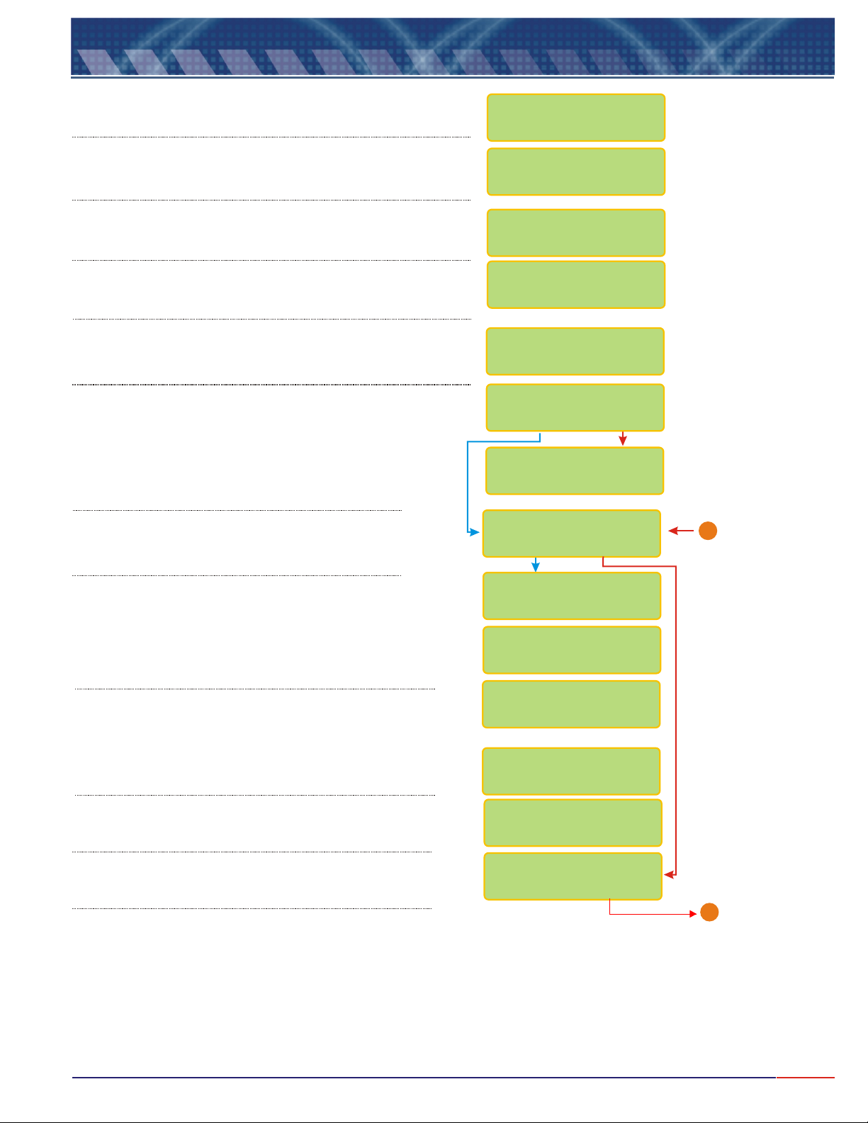
User can fully adjust the Standard value. Refer to page 11
(Note A) for instructions on how to modify this value.
In order to select the desired reference temperature, press
<SEL> <ENT>
key to confirm .
User can fully adjust the Reference Temperature value. Refer
to page 11 (Note A) for instructions on how to modify this
value.
User can fully adjust the Temperature Coefficient value. Refer
to page 11 (Note A) for instructions on how to modify this
value.
If chosen Manual, user will need to measure the process
temperature and inform if to the instrument while at Reading
Mode.
User can choose between the following Reading Modes:
Continuous - Read continuously
Average - Reads the average after time is set
User can program the time between Readings. Refer to
Page 11 (Note A)for instructions on how to adjust this
time.
key until the desired option flashes, then press
CALIBRAT.POINT
1412uS cm
/<>
:
REF. TEMPERATURE
ABSOLUTEREFER./
REF. TEMPERATURE
25 C ><
TEMPER.COEFF.
2.2% / C ><
TEMPER.COMPENS.
AUTOMANUAL/
READING MODE:
/CONTIN. AVER.
TIME BETWEEN
READINGS 5s <>
User can program the display to show information like
Barr graph, Contact, Current and more. Press
key until the desired option flashes, then press
key to confirm .
User can choose if desire to have Barr graph shown
above the Reading screen. When Bar Graph is
displayed, the information about Sensibility and Sample
Temperature will not be displayed!
User can now adjust the Minimum and Maximum
values for the Bar Graph. Refer to page 11(Note A) for
instructions on how to modify this value.
User can choose to display date/clock on display,
when equipment is turned off.
User can adjust date and clock, if desired.
<SELECT>
Use key to change numbers and when
finished, press key. If a mistake is made,
<ESCAPE>
press key to move back.
User has the option to configure Contacts SP 1, SP 2 and
SP 3. Press key to choose the desired option
then press key to confirm.
<ENTER>
<ENTER>
<SEL>
<ENT>
DISPLAY CONFIG.?
/ YES NO
BARGRAPH ?
/ YES NO
Min : 0uS
Max :100uS
/cm
/cm
CLOCK ?
/ YES NO
ADJUST CLOCK?
/ YES NO
15/06/2006
15:00:00
CONFIG CONTACTS?
/ YES NO
From Page 12
1
><
Go to Page 15
B
13
Page 15
9.1
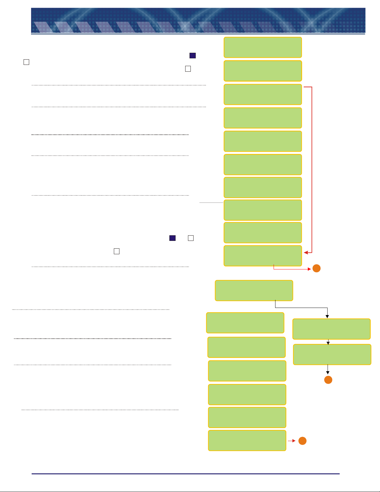
If user chooses Contact S1 as On, while at Reading Mode, a or a
will be displayed after the S1, indicating that this Contact is On. If
user chooses Contact S1 as Off, while at Reading Mode, a will be
displayed after the S1, indicating that this Contact is Off.
Equipment Operation-Conduct.-Set Up (cont.)
X
CONFIGURE
CONTACT S1
CONTACT S1 :
CONTACT S1 :
CONTACT S1 :
CONTACT S1 :
/ On Off
/ On Off
/ On Off
/ ON OFF
User can program the SP 1 for Alarm or PWM. Press key
until the desired option flashes, then press key to confirm .
User can adjust the value for SP 1.
Refer to Page 11 (Note A)for instruction on how to modify this
value.
User can choose the Acting desired.
Press key to choose the desired option then press
<SELECT>
<ENTER>
User can adjust the value for Hystereses, Proportional Band and
Period. Refer to Page 11 (Note A) for instruction on how to adjust
this value. Resolution will depend upon the Resolution chosen while
at Set Up. PB and Period will be accessed only if PWM was
chosen for the SP1.
For the Burn Out configuration, user will have three options as: On - Contact is
going to stay On all the time, Off - contact will stay Off all the time or Hold contact is going to follow the last situation, before going to Hold status.
Press key until the desired option flashes, then press to confirm. <SEL> <ENT>
If user chooses Contact S2 as On, while at Reading Mode, a or a will be
displayed after the S2, indicating that this Contact is On. If user chooses Contact
S2 as Off, while at Reading Mode, a will be displayed after the S2, indicating
that this Contact is Off.
key to confirm .
X
<ENT>
<SEL>
SET-POINT S1 :
/ PWMALARM
SET-POINT S1 :
100.0uS /cm <>
ACTING :
/ REVERSEDIRECT
HYSTERESES :
0.5uS /cm <>
P.B.:100% <
>
<
>PERIOD: 2s
CONFIG. BURN-OUT
STAND-BY: ON
Configure
Contact S2
CONTACT S2 :
CONTACT S2 :
/ On On
/ ON OFF
Go to Page 15
B
User can program the SP 1 for Alarm or PWM. Press key until
the desired option flashes, then press key to confirm .
User can adjust the value for SP 1(either Conductivity or Temperature..
Refer to Page 11 (Note A)for instruction on how to adjust this
value. Resolution will depend upon the Resolution chosen while
at Set Up.
User can choose the Acting desired.
Press key to choose the desired option then press
<ENTER>
User will be able to inform the Hystereses, Proportional Band and
period. Refer to Page 11 (Note A) for instruction on how to
adjust this values.
PB and Period will be accessed only if PWM was
chosen for the SP 2.
For the Burn Out configuration, user will have three options as:
On - Contact is going to stay On all the time, Off - contact will stay
Off all the time or Hold - contact is going to follow the last situation,
before going to Hold status. Press key until the desired
option flashes, then press to confirm.
key to confirm .
<ENT>
<ENT>
<SEL>
SET-POINT S2 :
ALARM/PWM/CLEAN
SET-POINT S2 :
150uS /cm <>
ACTING:
/ REVERSEDIRECT
HYSTERESES :
0.5uS /cm <>
PROPORT.BAND
100% <>
PERIOD :
2s <>
CONFIG. BURN-OUT
STAND-BY: OFF
Clean Interval:
24h <>
Clean Time:
60sec. <>
B
Go to Page 15
Go to Page 15
A
14
Page 16
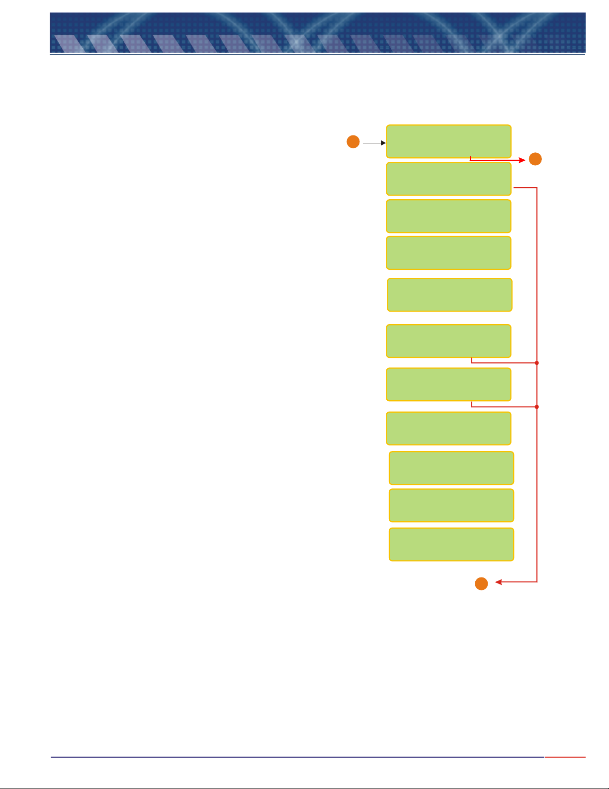
9.1
Equipment Operation-Conduct.-Set Up (cont.)
From Page 13 & 14
User is given the option to configure the burn out for mA
when the instrument goes to Stand By mode. Press key
until desired option flashes(4mA, 20mA or Hold), then press
<ENT>
Connect Amp Meter to output 4-20mA and it will be possible to adjust them,
then press <ENTER> when ready.
Adjust the value as needed by pressing (to decrease) or
<ESCAPE>
<SELECT>
(to increase) keys, so the outputs can be adjusted.
<ESCAPE>
key will decrease the value and key will increase.
key to confirm.
<SELECT>
<SEL>
B
CURRENT CONFIG.?
/ YES NO
OUTPUT mA
/ ON OFF
VALUE FOR 4mA:
0.00uS /cm <>
VALUE FOR 20mA:
200uS /cm <>
CONFIG. BURN-OUT
STAND-BY: 4mA
CALIBRATE mA?
/ YES NO
CONFIRM ?
/ YES NO
Place Ampmeter @
Output 4-20: mA
READY ?
Go to
1
Page 16
ADJUST: 4mA
<SEL> - <ESC> +
ADJUST: 20mA
<SEL> - <ESC> +
Go to Page 16
1
15
Page 17
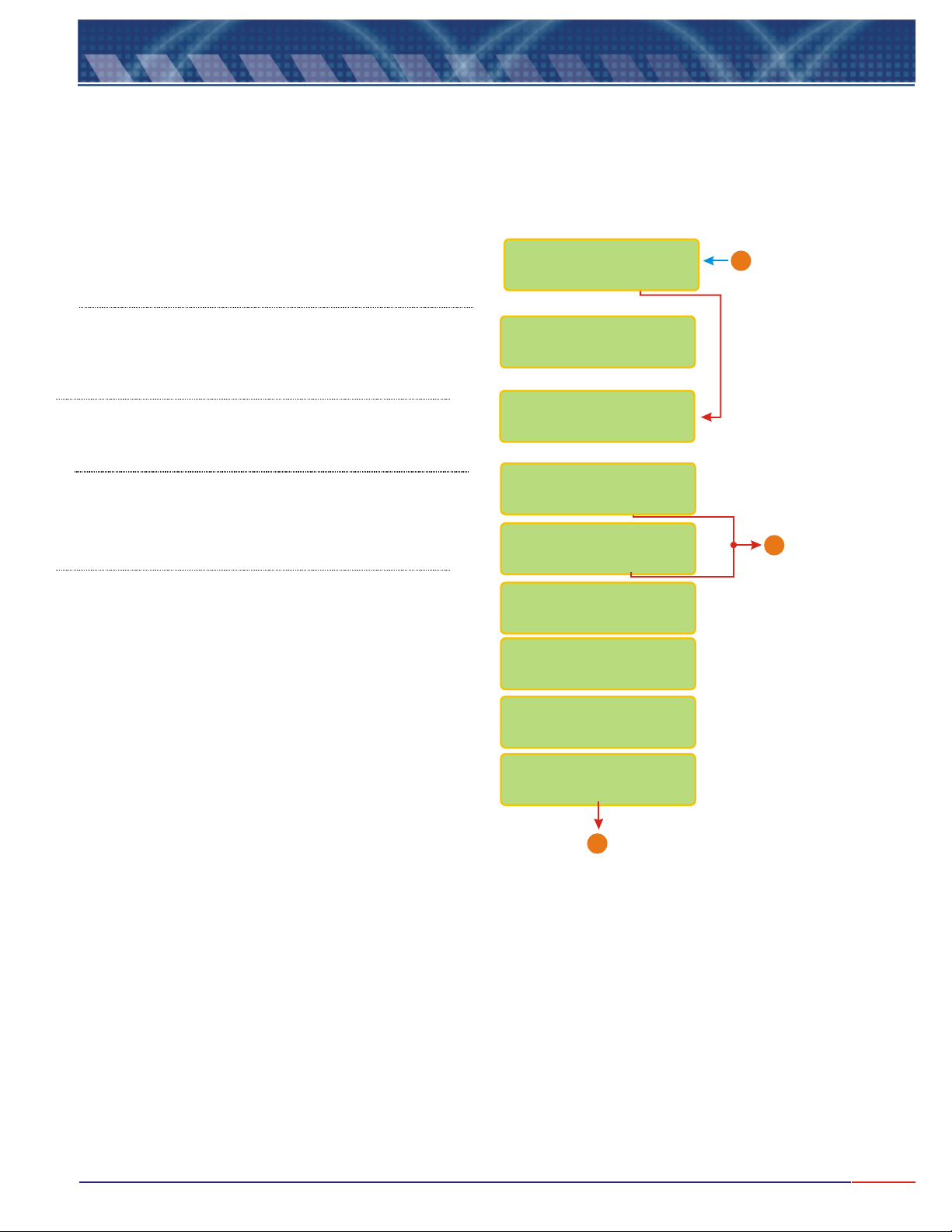
9.1
Equipment Operation-Conduct.-Set Up (cont.)
User will have the option to configure digital output RS-485 for
Proprietary Protocol. Press key to choose the desired
option then press key to confirm .
User will be able to define the instrument identification number
within the network, up to 256 instruments. Refer to Page 11 (Note
A) for instruction on how to adjust this value.
User will be able to inform the Temperature Cable Length. Refer to
Page 10 (Note A) for instruction on how to adjust this value. From
O thru 99meters.
If user is replacing the Cell of the instrument,
it is necessary to adjust its temperature.
If replacing the Cell, choose
First find out any sample temperature (any sample,
like tap water), then adjust the temperature at the
screen, to match the sample temperature being used.
Refer to page 11 (Note A) for instruction on how to
modify this value. Dip the Thermo into the used
sample, then press
<ENTER>
Yes and confirm.
key.<ENTER>
CONFIG RS485 ?
/ Yes No
Communication-ID
Number: 1 <>
TEMP. CABLE
LENGTH: 1.0m <>
CHANGE CELL?
/ Yes No
CONFIRM ?
/ Yes No
Thermostatize
Cell@ 25.0ºC<>
Thermostatize
Cell@ 25.0ºC<E>
From Page 15
1
X
END
WAIT
STABILIZATION
END
X
16
Page 18
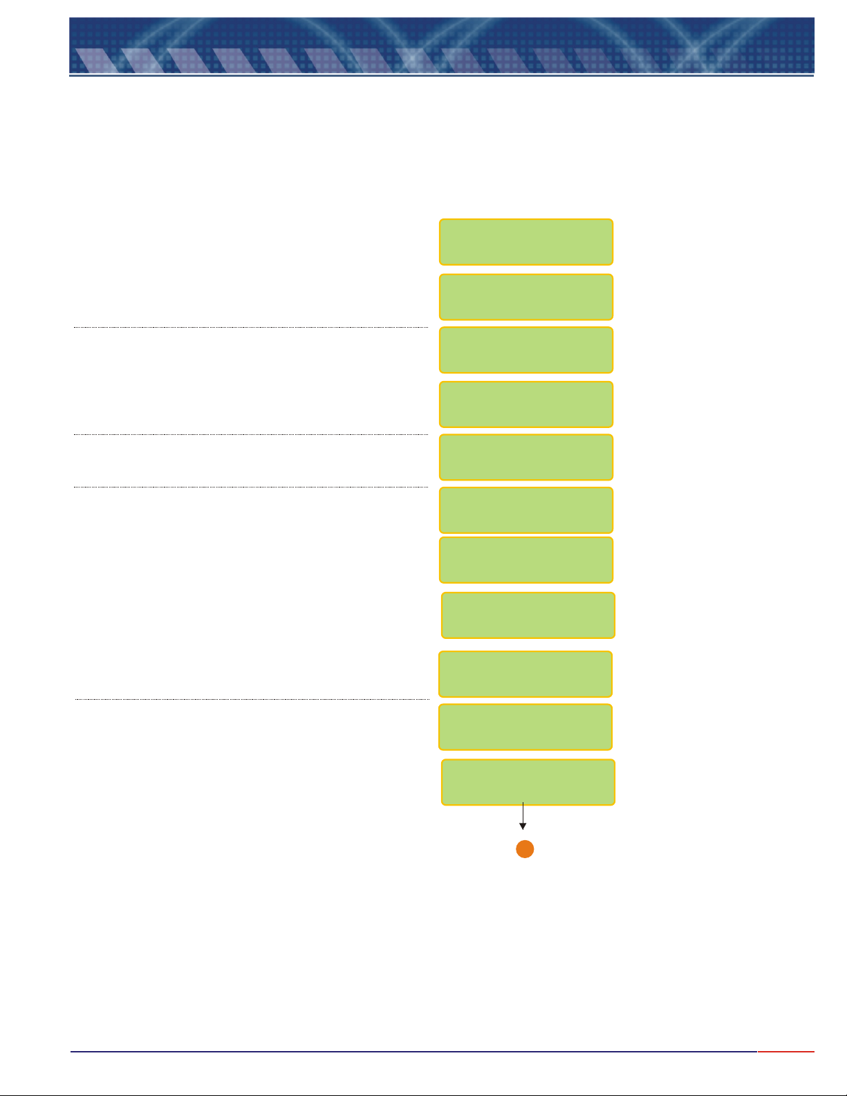
9.2
Press key until flashes, then
press to confirm the option chosen.
Press key until flashes, then press
<ENT>
Equipment Operation - Conduct. - Calibration
<SEL> Conductivity
<ENT>
<SEL> Read
to confirm the option chosen.
SELECT FUNCTION
/RES./CONC.COND.
COND.: /
Set Up / Check
Press key until flashes, then press
<SEL> Calibrate
<ENT>
Press key when Ready!<ENT>
to confirm the option chosen.
Dip cell at Standard 1412uS/cm, like chosen during
Set Up operation, based on Cell constant.
Press key when Ready!<ENT>
Wash electrode using plenty of water.
COND.: R / ead
WAIT
PLACE CELL
@ STD
1412uS/cm
READY ?
WAIT
CELL CONSTANT(K)
1.0cm-1
WASH CELL!
READY ?
Go to Sample!
Ready?
1
Go to Page 18
17
Page 19
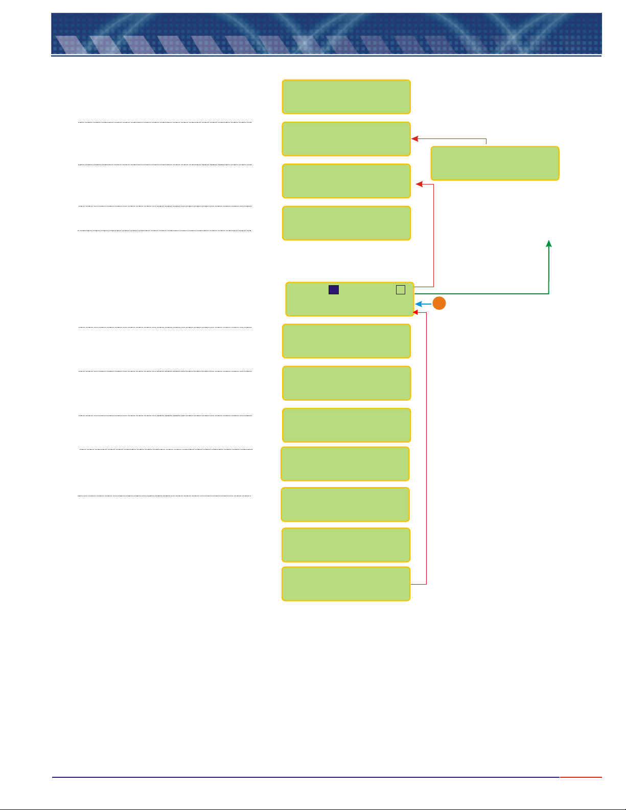
9.3
Equipment Operation - Conductivity - Read
<SEL> Conductivity
Press until flashes,
then press o confirm.
Press until flashes,
then press to confirm.
Press until flashes,
then press to confirm.
When Ready, press key<ENT>
After the Reading is performed the
following screen will be displayed. In
order to place the instrument in
Stand-by Model, press key
and press key to go back.
Refer to instructions on Page 11(***)
In order to advance, press key<SEL>
In order to advance, press key<SEL>
In order to advance, press key<SEL>
<ENT> t
<SEL> Read
<ENT>
<SEL> Read
<ENT>
<ENT>
<ESC>
SELECT FUNCTION
/RES./CONC.COND.
COND.: /
Set Up / Check
COND.: /
Calibrate
Go to Sample!
Ready?
S1: S2:
X
70.60 uS/cm@25ºC
1.000cm 25.0ºC
70.60 uS/cm@25ºC
Clean.Time:23:52
70.60 uS/cm
STAND-BY
In order to exit the stand-by mode,
<ENT>
press key again or hold
<ESC>
To move back to the main
menu. Refer to instructions on
Page 10
From Page 17
B
In order to advance, press key<SEL>
In order to adjust the value read,
<SEL> Man
Press key, if chosen ,
During Set Up, for On Line Calibr..
If during Set Up, user had chosen
Temperature Compensation as Manual, it
would be necessary to inform the process
Temperature at this point. Refer to page
11 (Note A) for instructions on how to
adjust this value.
mA: 10.00mA
ON LINE CALIBRAT
70.60uS/cm <>
ON LINE CALIBR.
68.00uS/cm
TEMP.COMP.MANUAL
25 ºC <>
TEMP.COMP.MANUAL
22.5 ºC
Press and hold <ESC> key for about 5seconds in
order to exit the Readng Mode.
Note: while during Reading, user can press <ENT> key
in order to place the equipment in Stand By Mode.
18
Page 20
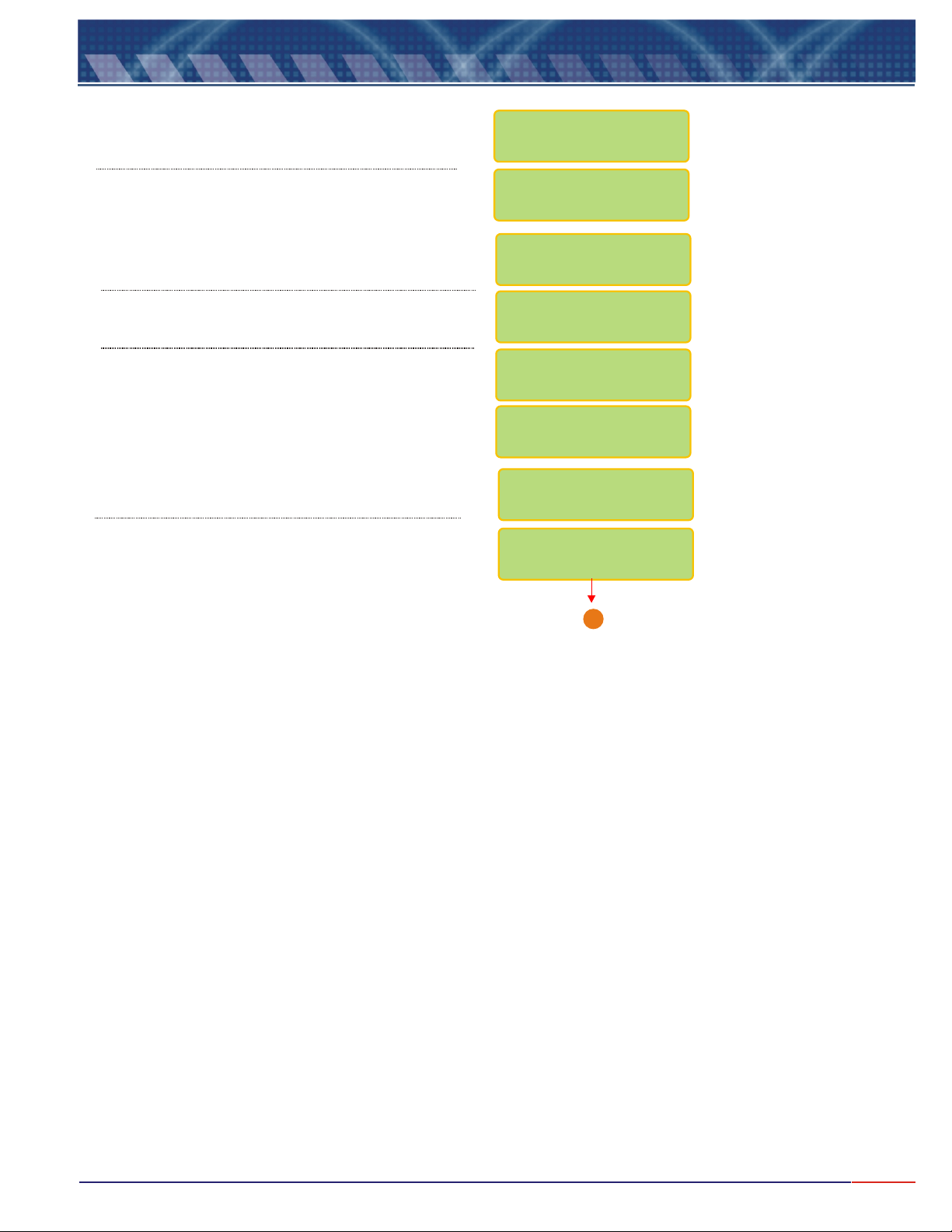
9.4
Equipment Operation - Conductivity - Check
<SEL> Conductivity
Press until flashes, then press
<ENT>
to confirm.
SELECT FUNCTION
/RES./CONC.COND.
Press until flashes, then press
<ENT>
Wash Cell using plenty of water.
Press key when Ready!<ENT>
<SEL> Check
to confirm.
Dip Cell at Standard shown. This value depends on
the Cell constant being used.
Press key when Ready!<ENT>
COND. : R /
Set Up Check
CELL CHECK
PLACE CELL @ STD
1412uS/cm
Ready?
WASH CELL
READY ?
Go to Page 20
ead
/
WAIT
A
19
Page 21
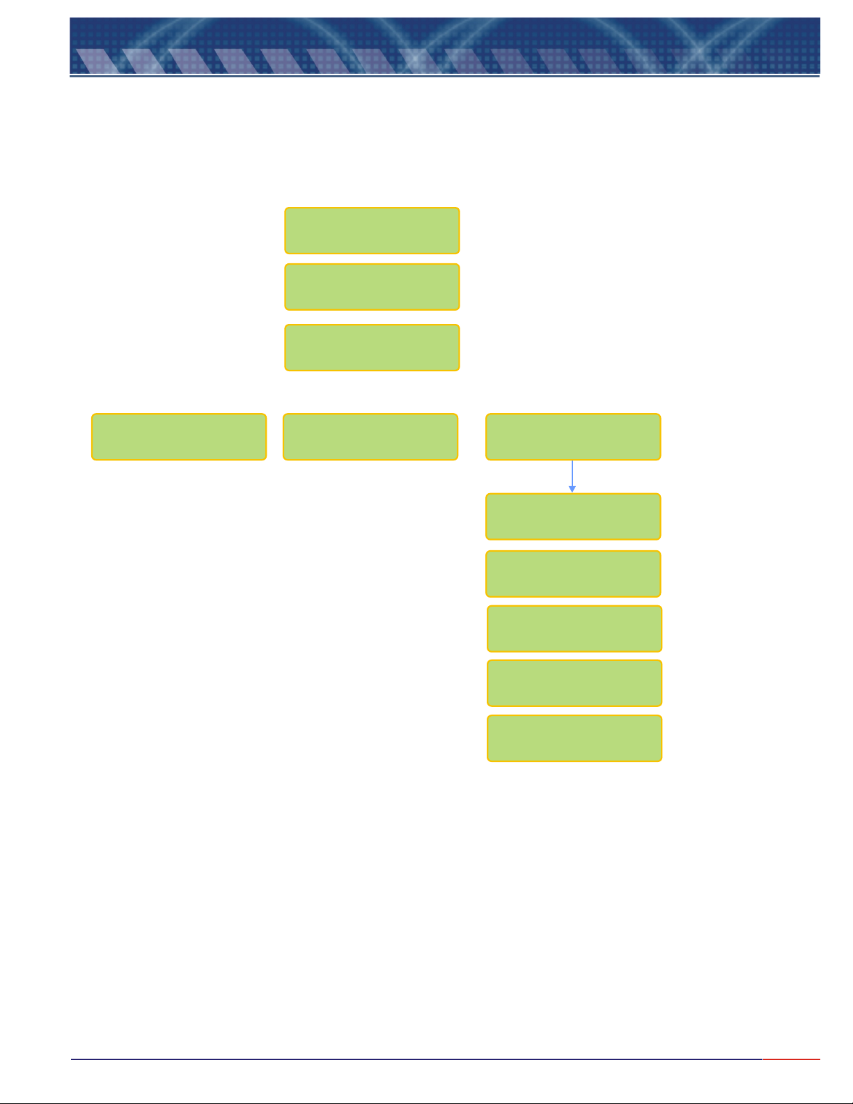
9.4
Equip. Operation - Conductivity - Check(cont.)
Check Result
CELL CONSTANT
(K) _......
CELL IS
Good
Very Good Bad <ENTER>
CHECK CELL
CHECK SOLUTION
WASH CELL USING
SAMPLE SOLVENT
PERSISTING
BAD
CONTACT OMEGA
CUST.SERVICE
(800)872-9436
20
Page 22
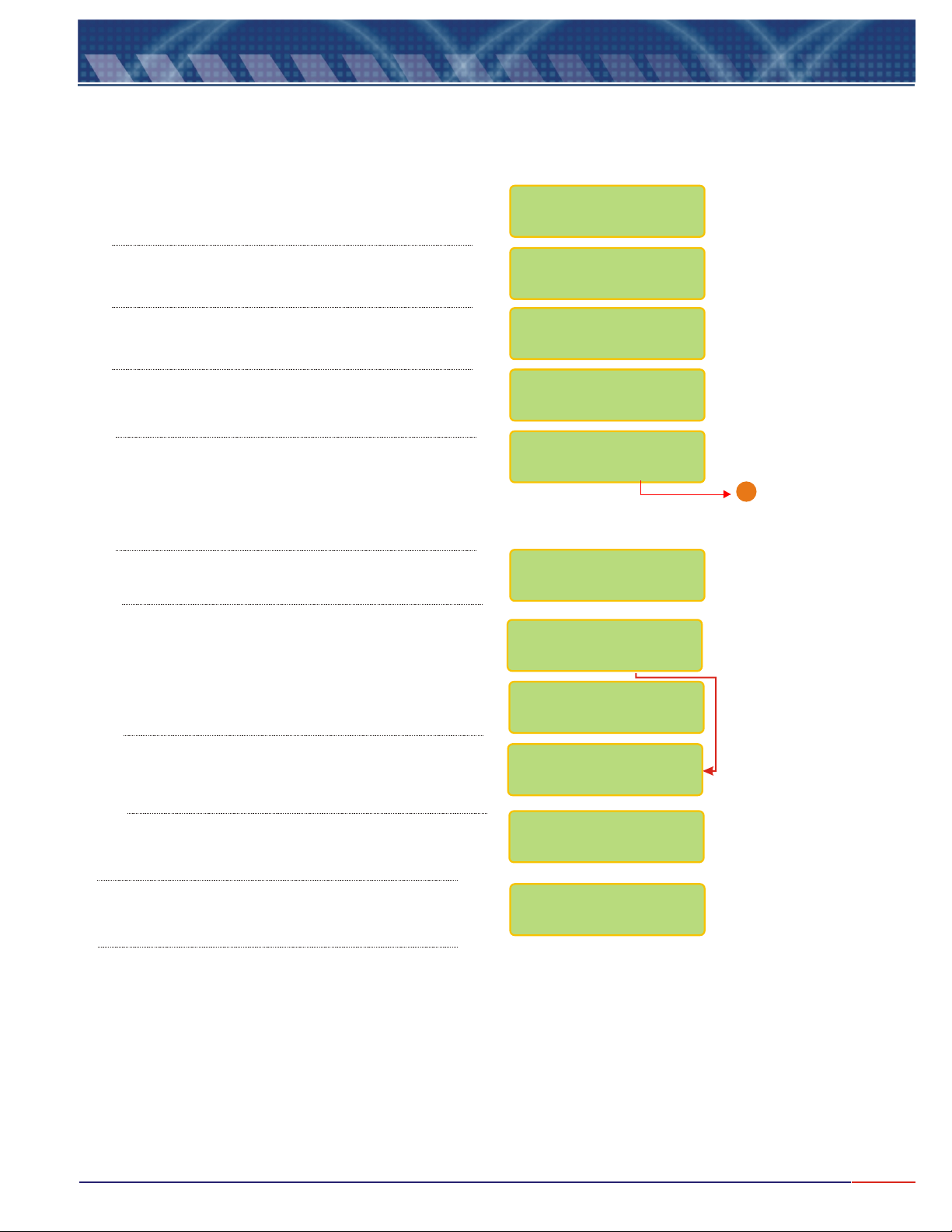
9.5
At the beginning of every operation, verify the Set Up conditions of the equipment and certify the parameters are correct
for your application.
Press option flashes,
then press key to confirm.
Equipment Operation - Resistivity - Set Up
<SEL> key until Resistivity
<ENT>
Press until flashes then press
<SEL> Set Up
<ENT>
key.
SELECT FUNCTION
/ /CONC.COND. RES.
RESIS. : /
READ
/ CHECK
A Password is required in order to access the .
Press in sequence , and keys.
In order to select the desired language, press
<SEL>
press key to confirm.
User can program the instrument, such as Electrode
type, Resolution and more. If chosen , the last
configuration will remain in effect. Press key
until the desired option flashes, then press
key to confirm.
You can calibrate the instrument as factory default.
Choose and confirm and the instrument will
calibrate as factory default! This option is offered in case
the user does have any other way to perform a
calibration procedure.
key until the desired option flashes, then
<ENT>
The Unit cannot be changed. It is default from factory.
The user will be able to choose the Cell Constant.
Press until the desired option flashes then
confirm by presssing .
<SEL> <ENT> <ESC>
No
<ENT>
SET UP
<SEL>
<ENT>
PASSWORD
_ _ _
LANGUAGE:
PORTUG
/SPANISH
CONFIG.INSTRUM.?
/ YES NO
UNIT:
Ohms(R)
FACTORY DEFAULT?
/ YES NO
CONFIRM ?
/ YES N0
CELL CONST.(K):
0.01/ / /5/100.1 1
Go to page 22
1
The Range cannot be changed. It is default from factory,
depending only on the Cell Constant chosen.
The user will be allowed to adjust the pH value read
at sample. Press until the desired option
flashes then confirm by presssing .
<ENT>
RANGE:
5R - INFINITY
ON LINE CAL.:
/ YES NO
21
Page 23
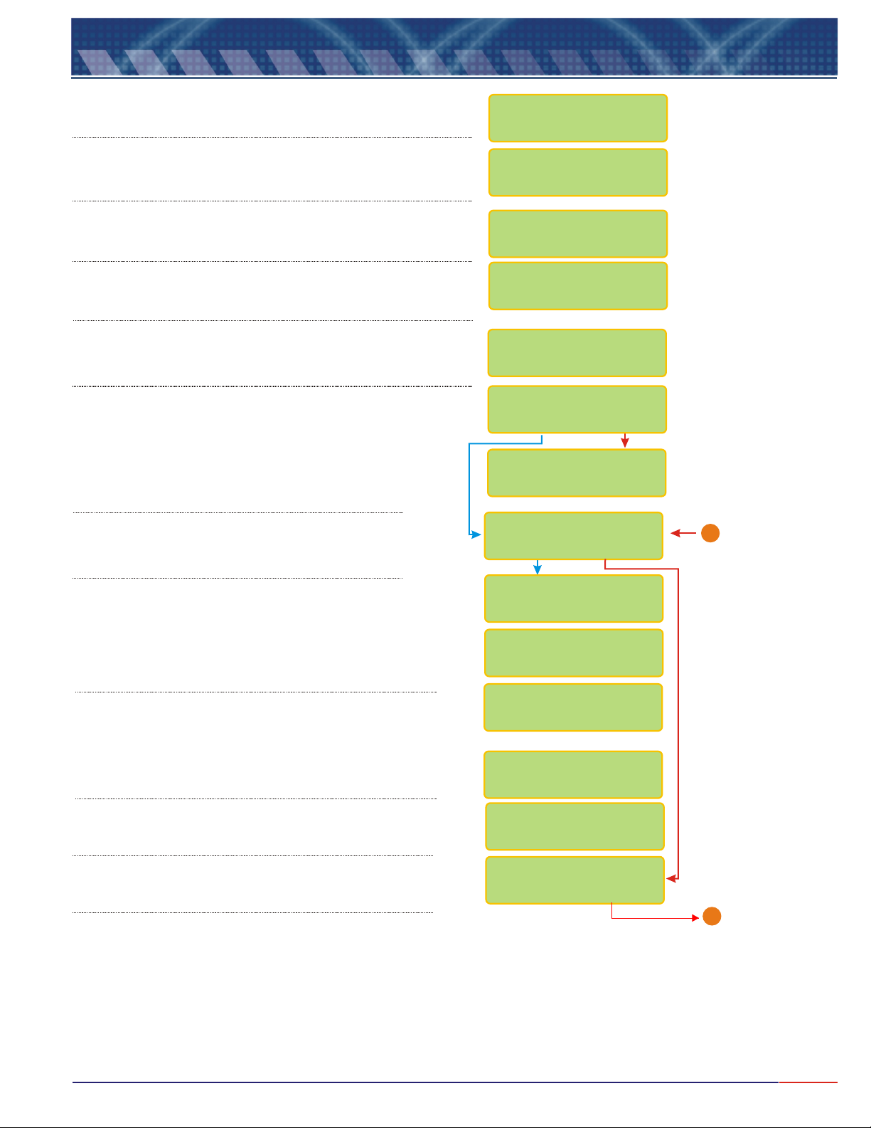
9.5
Equipment Operation-Resistivity-Set Up(cont.)
User can fully adjust the Standard value. Refer to page 11
(Note A) for instructions on how to modify this value.
In order to select the desired reference temperature, press
<SEL> <ENT>
key to confirm .
User can fully adjust the Reference Temperature value. Refer
to page 11 (Note A) for instructions on how to modify this
value.
User can fully adjust the Temperature Coefficient value. Refer
to page 11 (Note A) for instructions on how to modify this
value.
If chosen Manual, user will need to measure the process
temperature and inform if to the instrument while at Reading
Mode.
User can choose between the following Reading Modes:
Continuous - Read continuously
Average - Reads the average after time is set
User can program the time between Readings. Refer to
Page 11 (Note A)for instructions on how to adjust this
time.
key until the desired option flashes, then press
CALIBRAT.POINT
1412uS cm
/<>
:
REF. TEMPERATURE
ABSOLUTEREFER./
REF. TEMPERATURE
25 C ><
TEMPER.COEFF.
2.2% / C ><
TEMPER.COMPENS.
AUTOMANUAL/
READING MODE:
/CONTIN. AVER.
TIME BETWEEN
READINGS 5s <>
User can program the display to show information like
Barr graph, Contact, Current and more. Press
key until the desired option flashes, then press
key to confirm .
User can choose if desire to have Barr graph shown
above the Reading screen. When Bar Graph is
displayed, the information about Sensibility and Sample
Temperature will not be displayed!
User can now adjust the Minimum and Maximum
values for the Bar Graph. Refer to page 11(Note A) for
instructions on how to modify this value.
User can choose to display date/clock on display,
when equipment is turned off.
User can adjust date and clock, if desired.
<SELECT>
Use key to change numbers and when
finished, press key. If a mistake is made,
<ESCAPE>
press key to move back.
User has the option to configure Contacts SP 1, SP 2 and
SP 3. Press key to choose the desired option
then press key to confirm.
<ENTER>
<ENTER>
<SEL>
<ENT>
DISPLAY CONFIG.?
/ YES NO
BARGRAPH ?
/ YES NO
Min : 0Rx
Max :100Rx
cm
cm
><
CLOCK ?
/ YES NO
ADJUST CLOCK?
/ YES NO
15/06/2006
15:00:00
CONFIG CONTACTS?
/ YES NO
From Page 21
1
Go to Page 24
B
22
Page 24
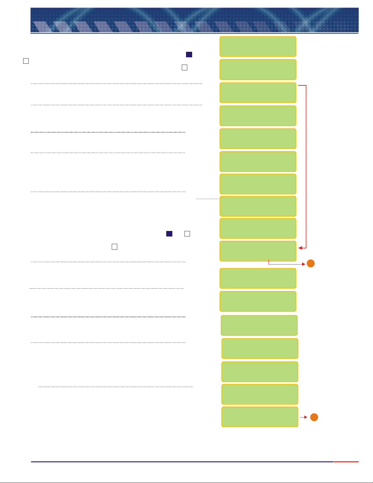
9.5
If user chooses Contact S1 as On, while at Reading Mode, a or a
will be displayed after the S1, indicating that this Contact is On. If
user chooses Contact S1 as Off, while at Reading Mode, a will be
displayed after the S1, indicating that this Contact is Off.
Equipment Operation-Resistivity-Set Up(cont.)
X
CONFIGURE
CONTACT S1
CONTACT S1 :
CONTACT S1 :
CONTACT S1 :
CONTACT S1 :
/ On Off
/ On Off
/ On Off
/ ON OFF
User can program the SP 1 for Alarm or PWM. Press key
until the desired option flashes, then press key to confirm .
User can adjust the value for SP 1.
Refer to Page 11 (Note A)for instruction on how to modify this
value.
User can choose the Acting desired.
Press key to choose the desired option then press
<SELECT>
<ENTER>
User can adjust the value for Hystereses, Proportional Band and
Period. Refer to Page 11 (Note A) for instruction on how to adjust
this value. Resolution will depend upon the Resolution chosen while
at Set Up. PB and Period will be accessed only if PWM was
chosen for the SP 1.
For the Burn Out configuration, user will have three options as: On - Contact is
going to stay On all the time, Off - contact will stay Off all the time or Hold contact is going to follow the last situation, before going to Hold status.
Press key until the desired option flashes, then press to confirm. <SEL> <ENT>
If user chooses Contact S2 as On, while at Reading Mode, a or a will be
displayed after the S2, indicating that this Contact is On. If user chooses Contact
S2 as Off, while at Reading Mode, a will be displayed after the S2, indicating
that this Contact is Off.
User can program the SP 1 for Alarm or PWM. Press key until
the desired option flashes, then press key to confirm .
key to confirm .
X
<ENT>
<ENT>
<SEL>
<SEL>
SET-POINT S1 :
/ PWMALARM
SET-POINT S1 :
100.0Rx cm <>
ACTING :
/ REVERSEDIRECT
HYSTERESES :
0.5Rx cm <>
P.B.:100% <
>
<
>PERIOD: 2s
CONFIG. BURN-OUT
STAND-BY: ON
Configure
Contact S2
CONTACT S2 :
CONTACT S2 :
/ On On
/ ON OFF
SET-POINT S2 :
ALARM/PWM/CLEAN
Go to Page 24
B
User can adjust the value for SP 1(either Conductivity or Temperature..
Refer to Page 11 (Note A)for instruction on how to adjust this
value. Resolution will depend upon the Resolution chosen while
at Set Up.
User can choose the Acting desired.
Press key to choose the desired option then press
<ENTER>
User will be able to inform the Hystereses, Proportional Band and
period. Refer to Page 11 (Note A) for instruction on how to
adjust this values.
PB and Period will be accessed only if PWM was
chosen for the SP 2.
For the Burn Out configuration, user will have three options as:
On - Contact is going to stay On all the time, Off - contact will stay
Off all the time or Hold - contact is going to follow the last situation,
before going to Hold status. Press key until the desired
option flashes, then press to confirm.
key to confirm .
<ENT>
SET-POINT S2 :
150Rx cm <>
ACTING:
/ REVERSEDIRECT
HYSTERESES :
0.5Rx cm <>
PROPORT.BAND
100% <>
PERIOD :
2s <>
CONFIG. BURN-OUT
STAND-BY: OFF
Go to Page 24
A
23
Page 25
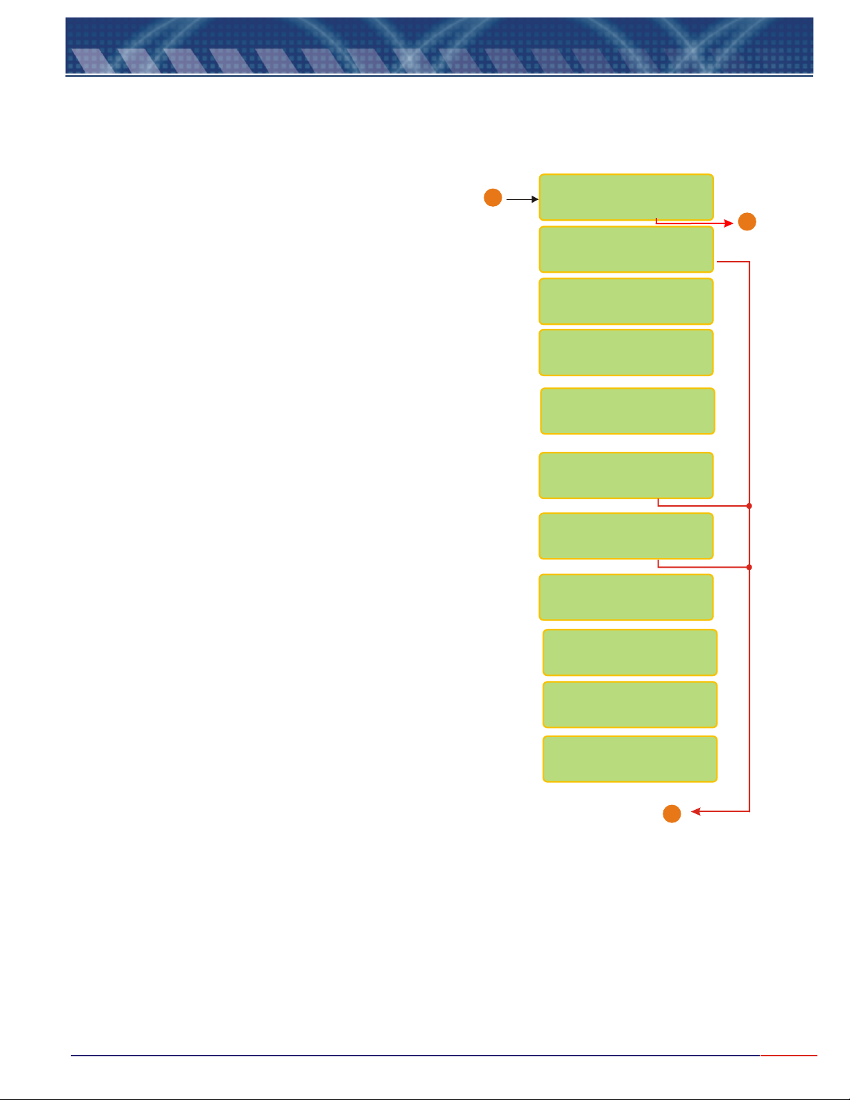
9.5
Equipment Operation-Resistiv.-Set Up (cont.)
From Page 22 & 23
User is given the option to configure the burn out for mA
when the instrument goes to Stand By mode. Press key
until desired option flashes(4mA, 20mA or Hold), then press
<ENT>
Connect Amp Meter to output 4-20mA and it will be possible to adjust them,
then press <ENTER> when ready.
Adjust the value as needed by pressing (to decrease) or
<ESCAPE>
<SELECT>
(to increase) keys, so the outputs can be adjusted.
<ESCAPE>
key will decrease the value and key will increase.
key to confirm.
<SELECT>
<SEL>
B
CURRENT CONFIG.?
/ YES NO
OUTPUT mA
/ ON OFF
VALUE FOR 4mA:
0.00Rxx cm <>
VALUE FOR 20mA:
200Rx cm <>
CONFIG. BURN-OUT
STAND-BY: 4mA
CALIBRATE mA?
/ YES NO
CONFIRM ?
/ YES NO
Place Ampmeter @
Output 4-20: mA
READY ?
Go to
1
Page 25
ADJUST: 4mA
<SEL> - <ESC> +
ADJUST: 20mA
<SEL> - <ESC> +
Go to Page 25
1
24
Page 26

9.5
Equipment Operation-Resistiv.-Set Up (cont.)
User will have the option to configure digital output RS-485 for
Proprietary Protocol. Press key to choose the desired
option then press key to confirm .
User will be able to define the instrument identification number
within the network, up to 256 instruments. Refer to Page 11 (Note
A) for instruction on how to adjust this value.
User will be able to inform the Temperature Cable Length. Refer to
Page 11 (Note A) for instruction on how to adjust this value. From
O thru 99meters.
<ENTER>
CONFIG RS485 ?
/ Yes No
Communication-ID
Number: 1 <>
TEMP. CABLE
LENGTH: 1.0m <>
END
X
From Page 24
1
25
Page 27
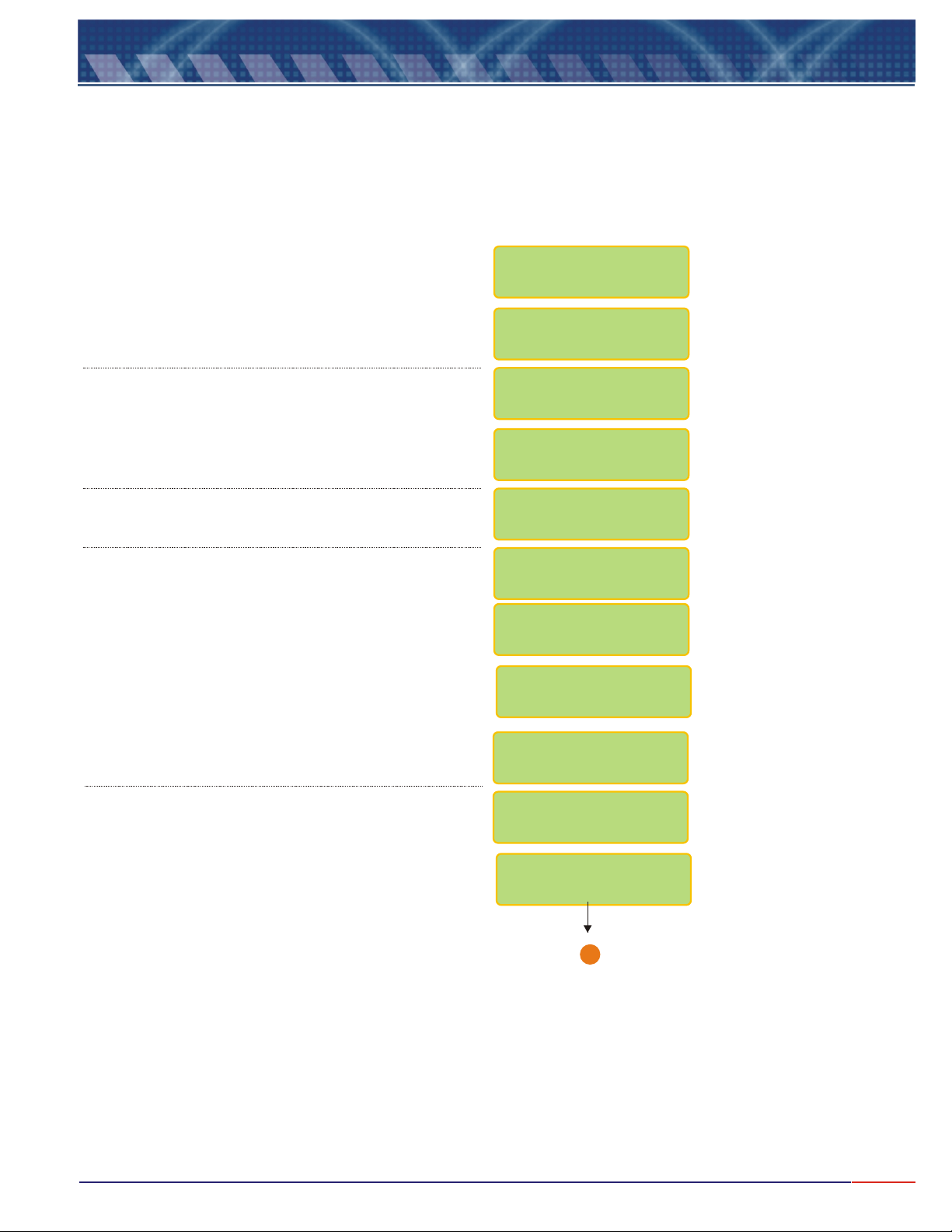
9.6
Press key until flashes, then press
<ENT>
Press key until flashes, then press
<ENT>
Equipment Operation - Resist. - Calibration
<SEL> Resistivity
to confirm the option chosen.
<SEL> Read
to confirm the option chosen.
SELECT FUNCTION
COND./ /CONC.RES.
RESIS.: /
Set Up / Check
Press key until flashes, then press
<SEL> Calibrate
<ENT>
Press key when Ready!<ENT>
to confirm the option chosen.
Dip cell at Standard 1412uS/cm, like chosen during
Set Up operation, based on Cell constant.
Press key when Ready!<ENT>
Wash electrode using plenty of water.
RESIS.: R / ead
WAIT
PLACE CELL
@ STD
1412uS/cm
READY ?
WAIT
CELL CONSTANT(K)
1.0cm-1
WASH CELL!
READY ?
Go to Sample!
Ready?
1
Go to Page 27
26
Page 28
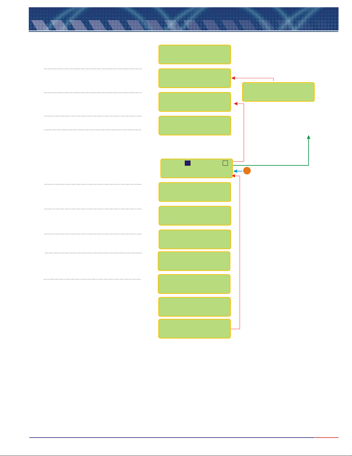
9.7
Equipment Operation - Resistivity - Read
<SEL> Resistivity
Press until flashes,
then press o confirm.
Press until flashes,
then press to confirm.
Press until flashes,
then press to confirm.
When Ready, press key<ENT>
After the Reading is performed the
following screen will be displayed. In
order to place the instrument in
Stand-by Model, press key
and press key to go back.
Refer to instructions on Page 10(***)
In order to advance, press key<SEL>
In order to advance, press key<SEL>
In order to advance, press key<SEL>
<ENT> t
<SEL> Read
<ENT>
<SEL> Read
<ENT>
<ENT>
<ESC>
SELECT FUNCTION
COND./ /CONC.RES.
RESIS.: /
Set Up / Check
RESIS.: /
Calibrate
Go to Sample!
Ready?
S1: S2:
X
70.60 Rxcm@25ºC
1.000cm 25.0ºC
70.60 Rxcm@25ºC
Clean.Time:23:52
70.60 Rxcm
STAND-BY
In order to exit the stand-by mode,
<ENT>
press key again or hold
<ESC>
To move back to the main
menu. Refer to instructions on
Page 10
From Page 17
B
In order to advance, press key<SEL>
In order to adjust the value read,
<SEL> Man
Press key, if chosen ,
During Set Up, for On Line Calibr..
If during Set Up, user had chosen
Temperature Compensation as Manual, it
would be necessary to inform the process
Temperature at this point. Refer to page
11 (Note A) for instructions on how to
adjust this value.
mA: 10.00mA
ON LINE CALIBRAT
70.60Rxcm <>
ON LINE CALIBR.
68.00uS/cm
TEMP.COMP.MANUAL
25 ºC <>
TEMP.COMP.MANUAL
22.5 ºC
Press and hold <ESC> key for about 5seconds in
order to exit the Readng Mode.
Note: while during Reading, user can press <ENT> key
in order to place the equipment in Stand By Mode.
27
Page 29
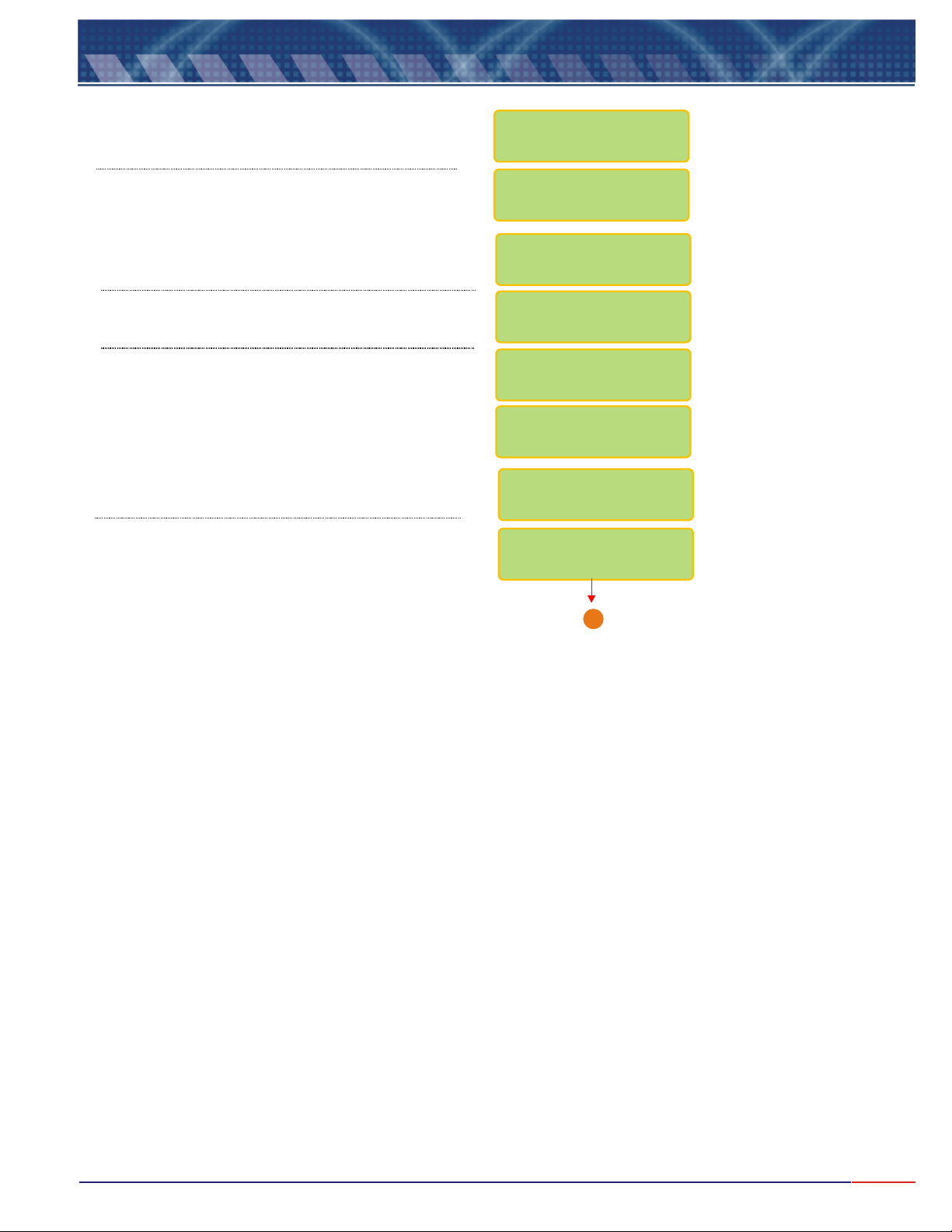
9.8
Equipment Operation - Resistivity - Check
<SEL> Resistiivity
Press until flashes, then press
<ENT>
to confirm.
SELECT FUNCTION
COND./ /CONC.RES.
Press until flashes, then press
<ENT>
Wash Cell using plenty of water.
Press key when Ready!<ENT>
<SEL> Check
to confirm.
Dip Cell at Standard shown. This value depends on
the Cell constant being used.
Press key when Ready!<ENT>
RESIS. : R /
Set Up Check
CELL CHECK
PLACE CELL @ STD
1412uS/cm
Ready?
WAIT
WASH CELL
READY ?
Go to Page 28
ead
/
A
28
Page 30
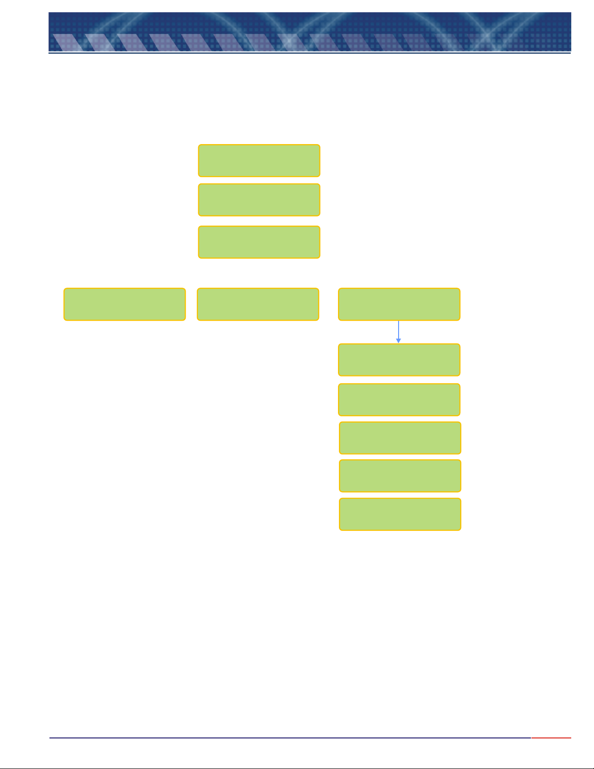
9.8
Equip. Operation - Resistivity - Check(cont.)
Check Result
CELL CONSTANT
(K) _......
CELL IS
Good
Very Good Bad <ENTER>
CHECK CELL
CHECK SOLUTION
WASH CELL USING
SAMPLE SOLVENT
PERSISTING
BAD
CONTACT OMEGA
CUST.SERVICE
(800)872-9436
29
Page 31
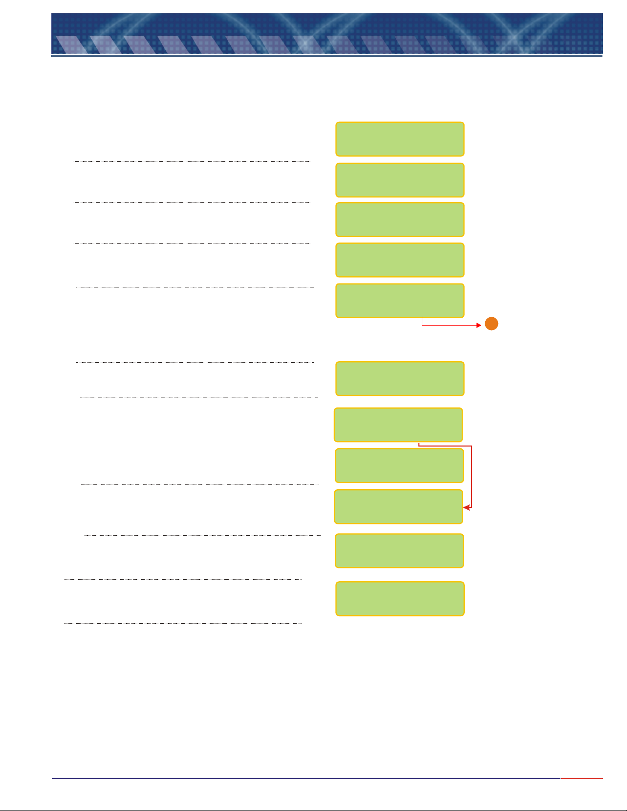
9.9
At the beginning of every operation, verify the Set Up conditions of the equipment and certify the parameters are correct
for your application.
Press option
flashes, then press key to confirm.
Equipment Operation -Concentration- Set Up
<SEL> key until Concentration
<ENT>
Press until flashes then press
<SEL> Set Up
<ENT>
key.
SELECT FUNCTION
/RES./COND. CONC.
COND. : /
READ
/ CHECK
A Password is required in order to access the .
Press in sequence , and keys.
In order to select the desired language, press
<SEL>
press key to confirm.
User can program the instrument, such as Electrode
type, Resolution and more. If chosen , the last
configuration will remain in effect. Press key
until the desired option flashes, then press
key to confirm.
You can calibrate the instrument as factory default.
Choose and confirm and the instrument will
calibrate as factory default! This option is offered in case
the user does have any other way to perform a
calibration procedure.
key until the desired option flashes, then
<ENT>
The Unit cannot be changed. It is default from factory.
The user will be able to choose the Cell Constant.
Press until the desired option flashes then
confirm by presssing .
<SEL> <ENT> <ESC>
No
<ENT>
SET UP
<SEL>
<ENT>
PASSWORD
_ _ _
LANGUAGE:
PORTUG
/SPANISH
CONFIG.INSTRUM.?
/ YES NO
UNIT:
PPM
FACTORY DEFAULT?
/ YES NO
CONFIRM ?
/ YES N0
CELL CONST.(K):
0.01/ / /5/100.1 1
Go to page 31
1
The Range cannot be changed. It is default from factory,
depending only on the Cell Constant chosen.
The user will be allowed to adjust the pH value read
at sample. Press until the desired option
flashes then confirm by presssing .
<ENT>
RANGE:
0 - 1000ppm
ON LINE CAL.:
/ YES NO
30
Page 32
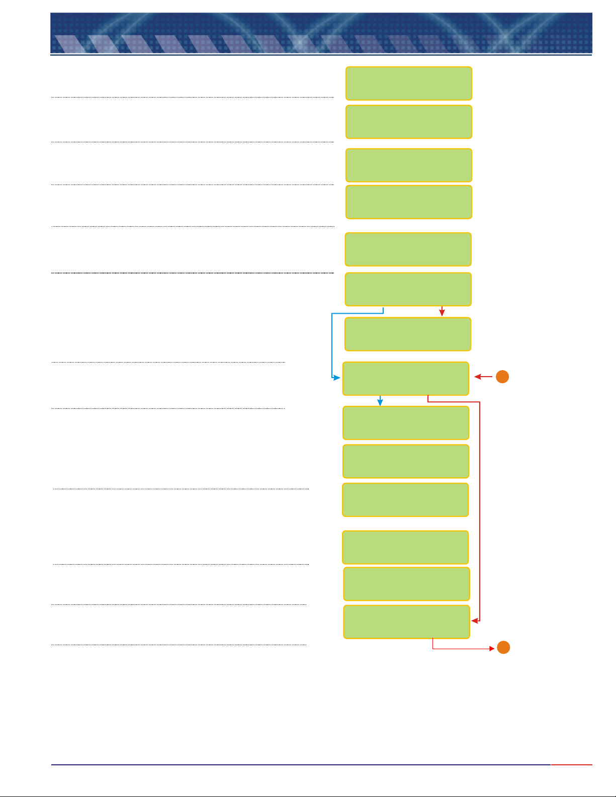
9.9
Equipment Operation-Concentr.-Set Up(cont.)
User can fully adjust the Standard value. Refer to page 11
(Note A) for instructions on how to modify this value.
In order to select the desired reference temperature, press
<SEL> <ENT>
key to confirm .
User can fully adjust the Reference Temperature value. Refer
to page 11 (Note A) for instructions on how to modify this
value.
User can fully adjust the Temperature Coefficient value. Refer
to page 11 (Note A) for instructions on how to modify this
value.
If chosen Manual, user will need to measure the process
temperature and inform if to the instrument while at Reading
Mode.
User can choose between the following Reading Modes:
Continuous - Read continuously
Average - Reads the average after time is set
User can program the time between Readings. Refer to
Page 11 (Note A)for instructions on how to adjust this
time.
key until the desired option flashes, then press
CALIBRAT.POINT
1412uS cm
/<>
:
REF. TEMPERATURE
ABSOLUTEREFER./
REF. TEMPERATURE
25 C ><
TEMPER.COEFF.
2.2% / C ><
TEMPER.COMPENS.
AUTOMANUAL/
READING MODE:
/CONTIN. AVER.
TIME BETWEEN
READINGS 5s <>
User can program the display to show information like
Barr graph, Contact, Current and more. Press
key until the desired option flashes, then press
key to confirm .
User can choose if desire to have Barr graph shown
above the Reading screen. When Bar Graph is
displayed, the information about Sensibility and Sample
Temperature will not be displayed!
User can now adjust the Minimum and Maximum
values for the Bar Graph. Refer to page 11(Note A) for
instructions on how to modify this value.
User can choose to display date/clock on display,
when equipment is turned off.
User can adjust date and clock, if desired.
<SELECT>
Use key to change numbers and when
finished, press key. If a mistake is made,
<ESCAPE>
press key to move back.
User has the option to configure Contacts SP 1, SP 2 and
SP 3. Press key to choose the desired option
then press key to confirm.
<ENTER>
<ENTER>
<SEL>
<ENT>
DISPLAY CONFIG.?
/ YES NO
BARGRAPH ?
/ YES NO
Min : 0ppm
Max :100pp
>m <
CLOCK ?
/ YES NO
ADJUST CLOCK?
/ YES NO
15/06/2006
15:00:00
CONFIG CONTACTS?
/ YES NO
From Page 30
1
Go to Page 33
B
31
Page 33
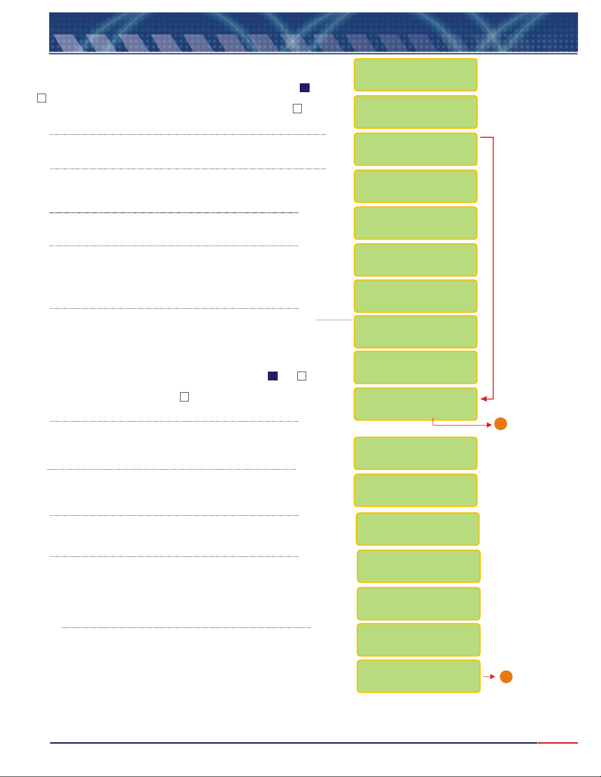
9.9
If user chooses Contact S1 as On, while at Reading Mode, a or a
will be displayed after the S1, indicating that this Contact is On. If
user chooses Contact S1 as Off, while at Reading Mode, a will be
displayed after the S1, indicating that this Contact is Off.
Equipment Operation-Concentr.-Set Up(cont.)
X
CONFIGURE
CONTACT S1
CONTACT S1 :
CONTACT S1 :
CONTACT S1 :
CONTACT S1 :
/ On Off
/ On Off
/ On Off
/ ON OFF
User can program the SP 1 for Alarm or PWM. Press key
until the desired option flashes, then press key to confirm .
User can adjust the value for SP 1.
Refer to Page 11 (Note A) for instruction on how to modify this
value.
User can choose the Acting desired.
Press key to choose the desired option then press
<SELECT>
<ENTER>
User can adjust the value for Hystereses, Proportional Band and
Period. Refer to Page 11 (Note A) for instruction on how to adjust
this value. Resolution will depend upon the Resolution chosen while
at Set Up. PB and Period will be accessed only if PWM was
chosen for the SP 1.
For the Burn Out configuration, user will have three options as: On - Contact is
going to stay On all the time, Off - contact will stay Off all the time or Hold contact is going to follow the last situation, before going to Hold status.
Press key until the desired option flashes, then press to confirm. <SEL> <ENT>
If user chooses Contact S2 as On, while at Reading Mode, a or a will be
displayed after the S2, indicating that this Contact is On. If user chooses Contact
S2 as Off, while at Reading Mode, a will be displayed after the S2, indicating
that this Contact is Off.
key to confirm .
X
<ENT>
<SEL>
SET-POINT S1 :
/ PWMALARM
SET-POINT S1 :
100.0Rx cm <>
ACTING :
/ REVERSEDIRECT
HYSTERESES :
0.5Rx cm <>
P.B.:100% <
>
<
>PERIOD: 2s
CONFIG. BURN-OUT
STAND-BY: ON
Configure
Contact S2
CONTACT S2 :
CONTACT S2 :
/ On On
/ ON OFF
Go to Page 33
B
User can program the SP 1 for Alarm or PWM. Press key until
the desired option flashes, then press key to confirm .
User can adjust the value for SP 1(either Conductivity or Temperature..
Refer to Page 11 (Note A)for instruction on how to adjust this
value. Resolution will depend upon the Resolution chosen while
at Set Up.
User can choose the Acting desired.
Press key to choose the desired option then press
<ENTER>
User will be able to inform the Hystereses, Proportional Band and
period. Refer to Page 11 (Note A) for instruction on how to
adjust this values.
PB and Period will be accessed only if PWM was
chosen for the SP 2.
For the Burn Out configuration, user will have three options as:
On - Contact is going to stay On all the time, Off - contact will stay
Off all the time or Hold - contact is going to follow the last situation,
before going to Hold status. Press key until the desired
option flashes, then press to confirm.
key to confirm .
<ENT>
<ENT>
<SEL>
SET-POINT S2 :
ALARM/PWM/CLEAN
SET-POINT S2 :
150Rx cm <>
ACTING:
/ REVERSEDIRECT
HYSTERESES :
0.5Rx cm <>
PROPORT.BAND
100% <>
PERIOD :
2s <>
CONFIG. BURN-OUT
STAND-BY: OFF
Go to Page 33
A
32
Page 34
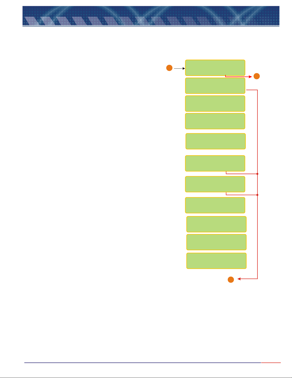
9.9
Equipment Operation-Concentr.-Set Up(cont.)
From Page 31 & 32
User is given the option to configure the burn out for mA
when the instrument goes to Stand By mode. Press key
until desired option flashes(4mA, 20mA or Hold), then press
<ENT>
Connect Amp Meter to output 4-20mA and it will be possible to adjust them,
then press <ENTER> when ready.
Adjust the value as needed by pressing (to decrease) or
<ESCAPE>
<SELECT>
(to increase) keys, so the outputs can be adjusted.
<ESCAPE>
key will decrease the value and key will increase.
key to confirm.
<SELECT>
<SEL>
B
CURRENT CONFIG.?
/ YES NO
OUTPUT mA
/ ON OFF
VALUE FOR 4mA:
0.00Rxx cm <>
VALUE FOR 20mA:
200Rx cm <>
CONFIG. BURN-OUT
STAND-BY: 4mA
CALIBRATE mA?
/ YES NO
CONFIRM ?
/ YES NO
Place Ampmeter @
Output 4-20: mA
READY ?
Go to
1
Page 34
ADJUST: 4mA
<SEL> - <ESC> +
ADJUST: 20mA
<SEL> - <ESC> +
Go to Page 34
1
33
Page 35
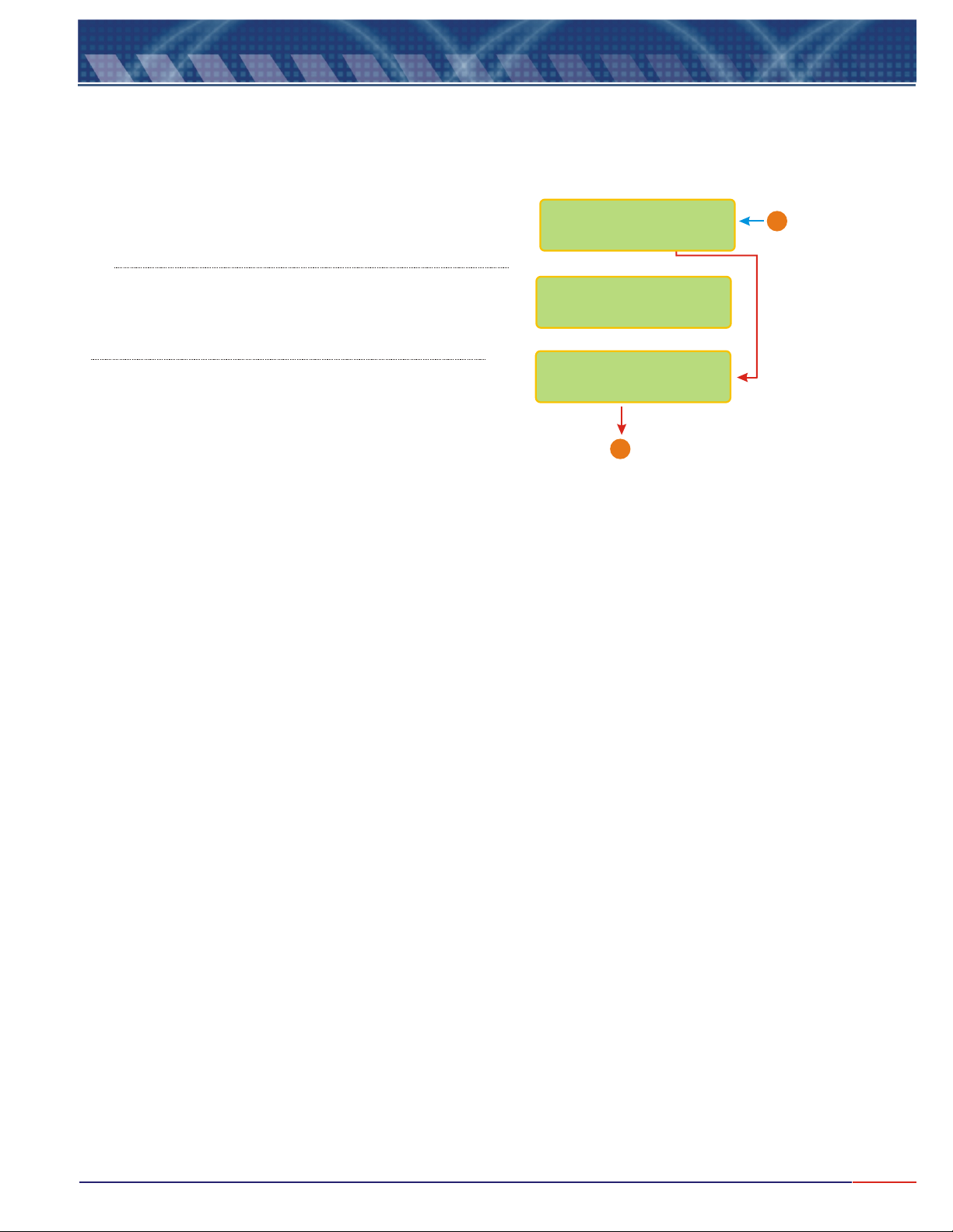
9.9
Equipment Operation-Concentr.-Set Up(cont.)
User will have the option to configure digital output RS-485 for
Proprietary Protocol. Press key to choose the desired
option then press key to confirm .
User will be able to define the instrument identification number
within the network, up to 256 instruments. Refer to Page 11 (Note
A) for instruction on how to adjust this value.
User will be able to inform the Temperature Cable Length. Refer to
Page 11 (Note A) for instruction on how to adjust this value. From
O thru 99meters.
<ENTER>
CONFIG RS485 ?
/ Yes No
Communication-ID
Number: 1 <>
TEMP. CABLE
LENGTH: 1.0m <>
END
X
From Page 33
1
34
Page 36
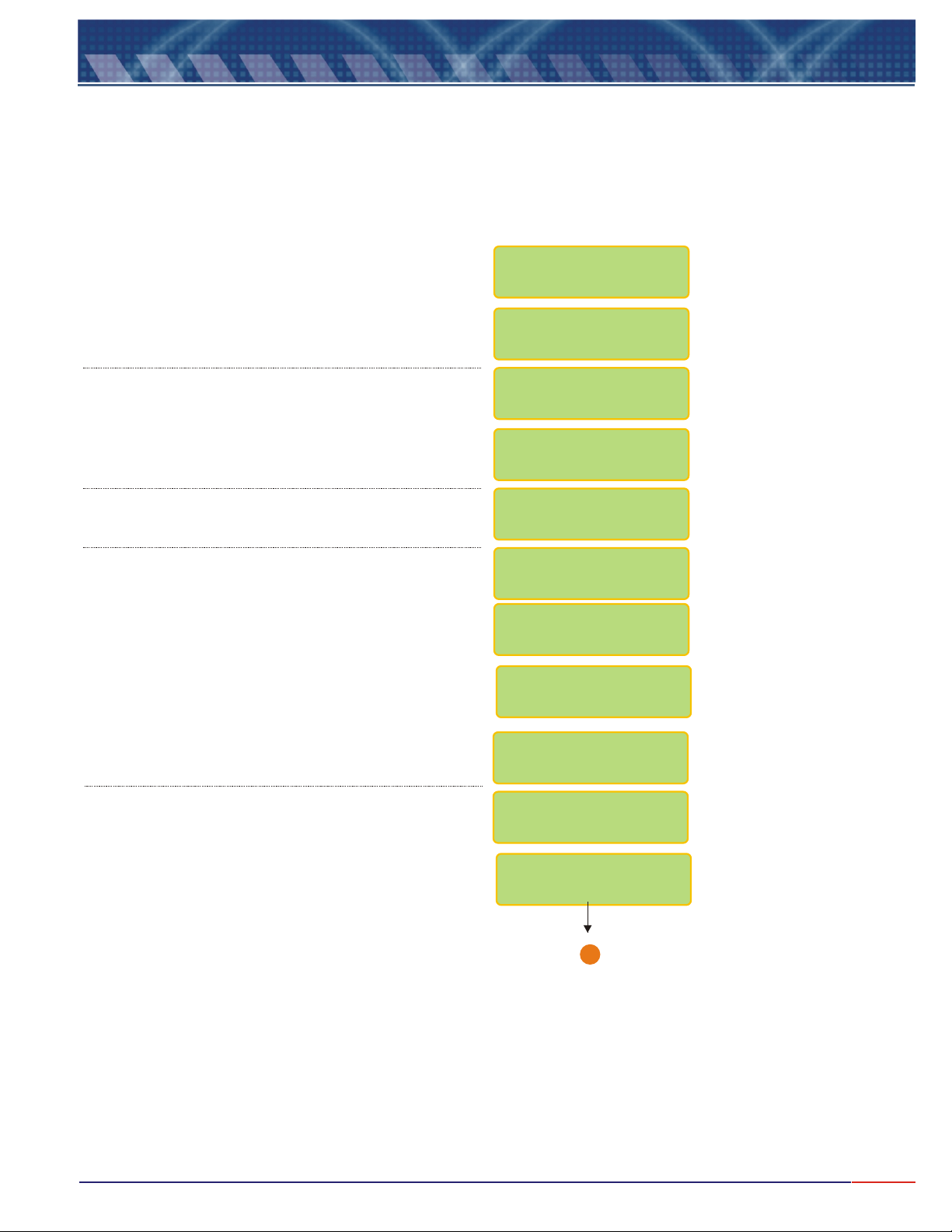
9.10
<SEL> Concentrtion
Press key until flashes, then
<ENT>
press to confirm the option chosen.
Press key until flashes, then press
<SEL> Read
<ENT>
Equipment Operation-Concentr. - Calibration
to confirm the option chosen.
SELECT FUNCTION
COND./RES./CONC.
CONC.: /
Set Up / Check
Press key until flashes, then press
<SEL> Calibrate
<ENT>
Press key when Ready!<ENT>
to confirm the option chosen.
Dip cell at Standard 1412uS/cm, like chosen during
Set Up operation, based on Cell constant.
Press key when Ready!<ENT>
Wash electrode using plenty of water.
CONC.: R / ead
WAIT
PLACE CELL
@ STD
1412uS/cm
READY ?
WAIT
CELL CONSTANT(K)
1.0cm-1
WASH CELL!
READY ?
Go to Sample!
Ready?
1
Go to Page 36
35
Page 37
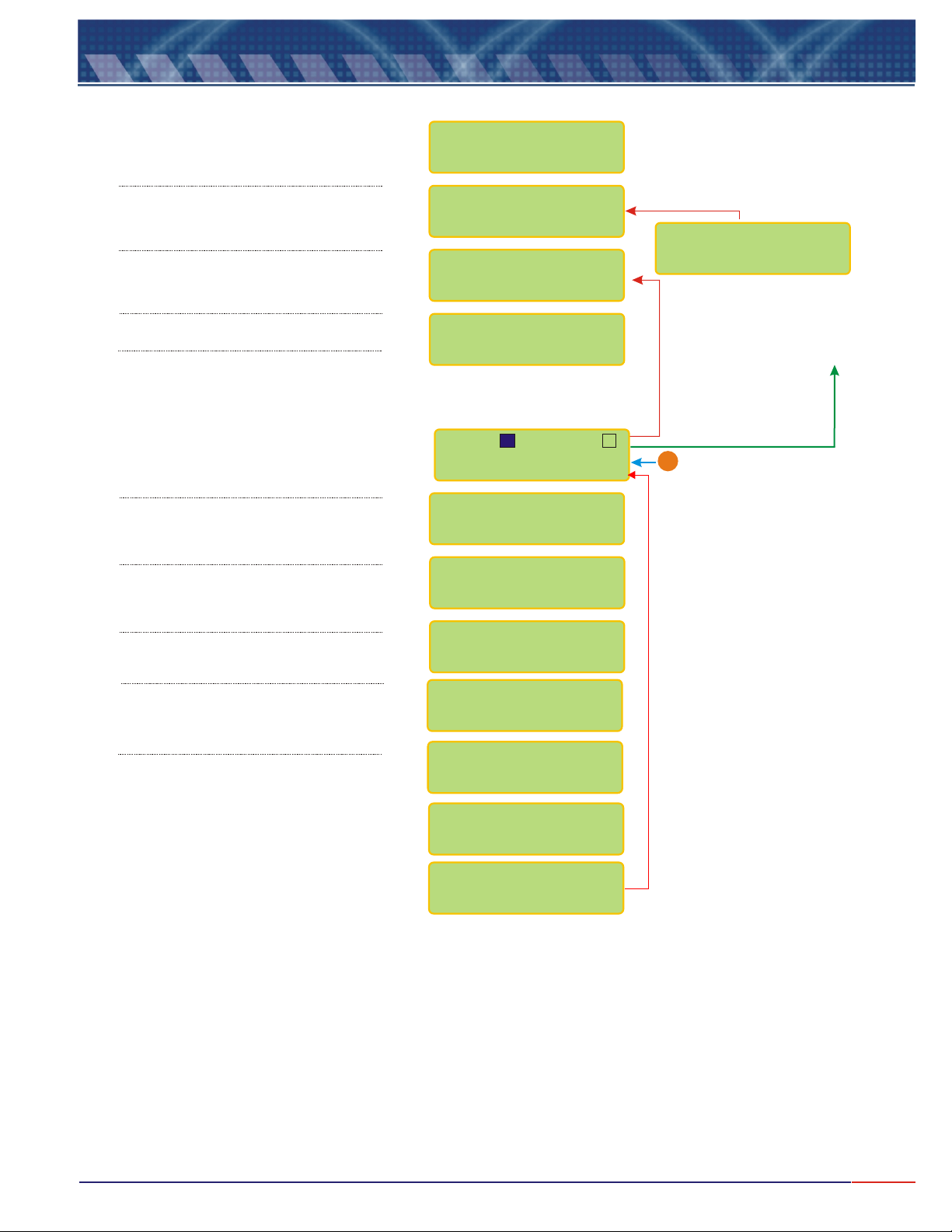
9.11
Equipment Operation -Concentration - Read
<SEL> Concentration
Press until flashes,
then press o confirm.
Press until flashes,
then press to confirm.
Press until flashes,
then press to confirm.
When Ready, press key<ENT>
After the Reading is performed the
following screen will be displayed. In
order to place the instrument in
Stand-by Model, press key
and press key to go back.
Refer to instructions on Page 10(***)
In order to advance, press key<SEL>
<ENT> t
<SEL> Read
<ENT>
<SEL> Read
<ENT>
<ENT>
<ESC>
SELECT FUNCTION
COND./RES./CONC.
1.000cm 25.0ºC
In order to advance, press key<SEL>
In order to advance, press key<SEL>
Clean.Time:23:52
CONC.: /
Set Up / Check
CONC.: /
Calibrate
Go to Sample!
Ready?
S1: S2:
X
70.60 ppm@25ºC
70.60 ppm@25ºC
70.60 ppm
STAND-BY
In order to exit the stand-by mode,
<ENT>
press key again or hold
<ESC>
To move back to the main
menu. Refer to instructions on
Page 10
From Page 35
B
In order to advance, press key<SEL>
In order to adjust the value read,
<SEL> Man
Press key, if chosen ,
During Set Up, for On Line Calibr..
If during Set Up, user had chosen
Temperature Compensation as Manual, it
would be necessary to inform the process
Temperature at this point. Refer to page
11 (Note A) for instructions on how to
adjust this value.
mA: 10.00mA
ON LINE CALIBRAT
70.60ppm <>
ON LINE CALIBR.
68.00ppm
TEMP.COMP.MANUAL
25 ºC <>
TEMP.COMP.MANUAL
22.5 ºC
Press and hold <ESC> key for about 5seconds in
order to exit the Readng Mode.
Note: while during Reading, user can press <ENT> key
in order to place the equipment in Stand By Mode.
36
Page 38
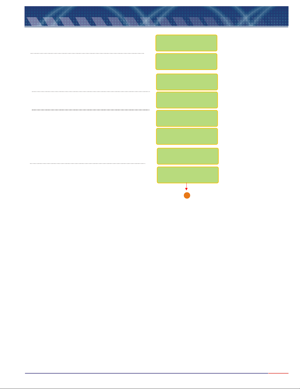
9.11
Press until flashes, then
press to confirm.
Equipment Operation -Concentration - Check
<SEL> Concentration
<ENT>
SELECT FUNCTION
COND./RES./CONC.
Press until flashes, then press
<ENT>
Wash Cell using plenty of water.
Press key when Ready!<ENT>
<SEL> Check
to confirm.
Dip Cell at Standard shown. This value depends on
the Cell constant being used.
Press key when Ready!<ENT>
CONC. : R /
Set Up Check
CELL CHECK
PLACE CELL @ STD
1412uS/cm
Ready?
WASH CELL
READY ?
Go to Page 38
ead
/
WAIT
A
37
Page 39
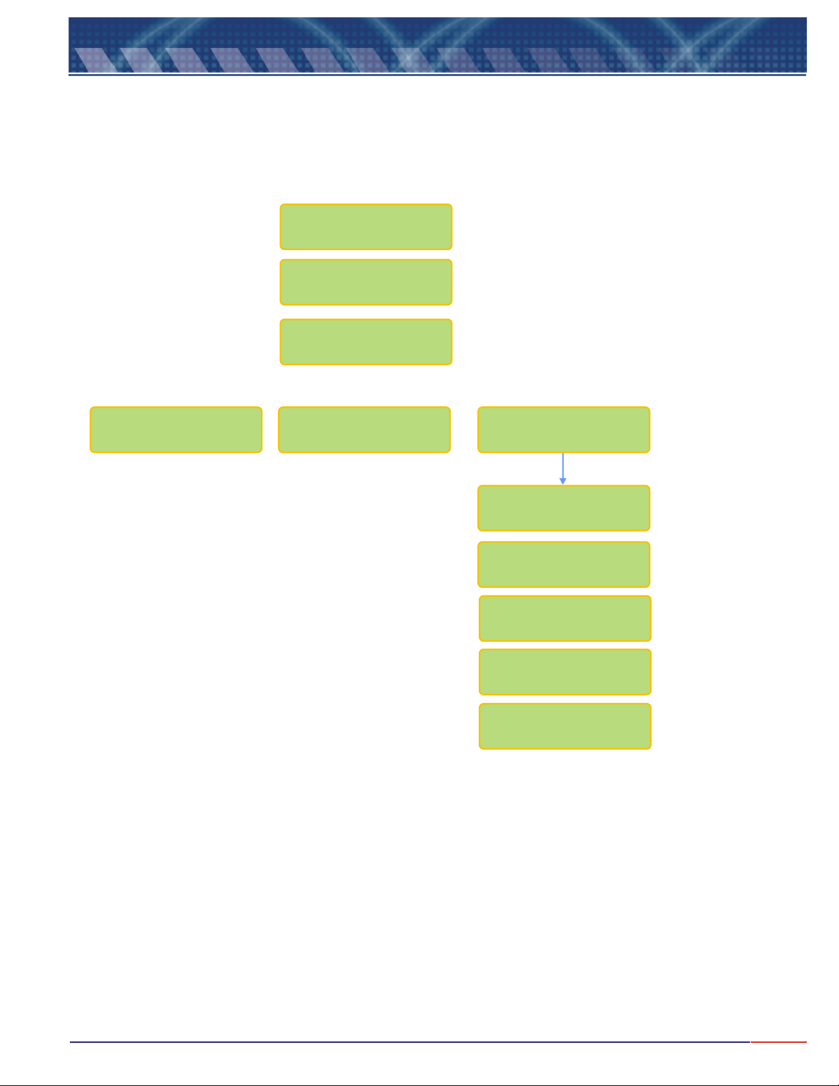
9.11
Equip. Operation -Concentr. - Check(cont.)
Check Result
CELL CONSTANT
(K) _......
CELL IS
Good
Very Good Bad <ENTER>
CHECK CELL
CHECK SOLUTION
WASH CELL USING
SAMPLE SOLVENT
PERSISTING
BAD
CONTACT OMEGA
CUST.SERVICE
(800)872-9436
38
Page 40

10.
Communication Protocol
Communication Protocol:
1) Proprietary:
Order:
ESC ID P CR LF
0x1B 0x50 0x0D 0x0A Hexadecimal
The ID is configured at the instrument from 1 to 32.
Answer:
L > > V V V V V V mS/cm C C C C C C m A
Example of answer for an un-stable value
L > 0. 02 mS/cm 1 2 . 0 0 m A
Example of answer for a stable value
L > > 0 . 02 mS/cm 1 2 . 0 0 m A
Note: a) When the answer comes a C instead of a L, it means that the equipment is under
calibration function (is being operated in location by the user, executing the calibration
operation at the instrument).
b) When the answer comes an S instead of a L, it means that the equipment is under Set Up
function and it is being operated in location by the user.
2) RS485 – It is a “physical location”, where the proprietary protocol will be “transported”.
As factory default, this communication comes configured as:
Speed = 9600
Parity = none
Number of Bits = 8
Stop Bit = 1
ID = 1
39
Page 41
Page 42
M-4515/0908
 Loading...