

Page 1
User’s Guide
TM
Shop online at
omega.com
e-mail: [email protected]
For latest product manuals:
www.omegamanual.info
DR-I3P
Isolated signal converter
with universal power supply
multi signal, DIN Rail Mount
Page 2

omega.com [email protected]
Servicing North America:
U.S.A. Omega Engineering, Inc.
Headquarters: 800 Connecticut Ave. Suite 5N01, Norwalk, CT 06854
Toll-Free: 1-800-826-6342 (USA & Canada only)
Customer Service: 1-800-622-2378 (USA & Canada only)
Engineering Service: 1-800-872-9436 (USA & Canada only)
Tel: (203) 359-1660 Fax: (203) 359-7700
e-mail: [email protected]
For Other Locations Visit omega.com/worldwide
The information contained in this document is believed to be correct, but OMEGA accepts no liability for any errors it contains, and
reserves the right to alter specications without notice.
Page 3

WARRANTY/DISCLAIMER
OMEGA ENGINEERING, INC. warrants this unit to be free of defects in materials and workmanship
for a period of 13 months from date of purchase. OMEGA’s WARRANTY adds an additional one (1)
month grace period to the normal one (1) year product warranty to cover handling and shipping
time. This ensures that OMEGA’s customers receive maximum coverage on each product.
If the unit malfunctions, it must be returned to the factory for evaluation. OMEGA’s Customer Service
Department will issue an Authorized Return (AR) number immediately upon phone or written request.
Upon examination by OMEGA, if the unit is found to be defective, it will be repaired or replaced at no
charge. OMEGA’s WARRANTY does not apply to defects resulting from any action of the purchaser,
including but not limited to mishandling, improper interfacing, operation outside of design limits,
improper repair, or unauthorized modification. This WARRANTY is VOID if the unit shows evidence of
having been tampered with or shows evidence of having been damaged as a
result of excessive corrosion; or current, heat, moisture or vibration; improper
specification; misapplication; misuse or other operating conditions outside of
OMEGA’s control. Components in which wear is not warranted, include but are not
limited to contact points, fuses, and triacs.
OMEGA is pleased to offer suggestions on the use of its various products. However,
OMEGA neither assumes responsibility for any omissions or errors nor
assumes
in accordance with information provided by OMEGA, either verbal or
written. OMEGA warrants only that the parts manufactured by it will be as
specified and free of defects. OMEGA MAKES NO OTHER WARRANTIES OR
REPRESENTATIONS OF ANY KIND WHATSOEVER, EXPRESS OR IMPLIED, EXCEPT
THAT OF TITLE, AND ALL IMPLIED WARRANTIES INCLUDING ANY WARRANTY OF
MERCHANTABILITY AND FITNESS FOR A PARTICULAR PURPOSE ARE HEREBY
DISCLAIMED. LIMITATION OF LIABILITY: The remedies of purchaser set forth herein are
exclusive, and the total liability of OMEGA with respect to this order, whether
based on contract, warranty, negligence, indemnification, strict liability or otherwise,
shall not exceed the purchase price of the component upon which liability
is based. In no event shall OMEGA be liable for consequential, incidental or special damages.
CONDITIONS: Equipment sold by OMEGA is not intended to be used, nor shall it be used: (1) as a
“Basic Component” under 10 CFR 21 (NRC), used in or with any nuclear installation or activity; or (2)
in medical applications or used on humans. Should any Product(s) be used in or with any nuclear
installation or activity, medical application, used on humans, or misused in any way, OMEGA assumes
no responsibility as set forth in our basic WARRANTY / DISCLAIMER language, and, additionally,
purchaser will indemnify OMEGA and hold OMEGA harmless from any liability or damage whatsoever
arising out of the use of the Product(s) in such a manner.
liability for any damages that result from the
use of its products
RETURN REQUESTS/INQUIRIES
Direct all warranty and repair requests/inquiries to the OMEGA Customer Service Department.
BEFORE RETURNING ANY PRODUCT(S) TO OMEGA, PURCHASER MUST OBTAIN AN AUTHORIZED
RETURN (AR) NUMBER FROM OMEGA’S CUSTOMER SERVICE DEPARTMENT (IN ORDER TO AVOID
PROCESSING DELAYS). The assigned AR number should then be marked on the outside of the return
package and on any correspondence.
The purchaser is responsible for shipping charges, freight, insurance and proper packaging to prevent
breakage in transit.
FOR WARRANTY RETURNS, please have the
following information available BEFORE
contacting OMEGA:
1. Purchase Order number under which the
product was PURCHASED,
2. Model and serial number of the product under
warranty, and
3. Repair instructions and/or specific problems
relative to the product.
OMEGA’s policy is to make running changes, not model changes, whenever an improvement is possible. This affords
our customers the latest in technology and engineering.
OMEGA is a trademark of OMEGA ENGINEERING, INC.
© Copyright 2019 OMEGA ENGINEERING, INC. All rights reserved. This document may not be copied, photocopied,
reproduced, translated, or reduced to any electronic medium or machine-readable form, in whole or in part, without the
prior written consent of OMEGA ENGINEERING, INC.
FOR NON-WARRANTY REPAIRS,
for current repair charges. Have the following
information available BEFORE contacting OMEGA:
1. Purchase Order number to cover the COST
of the repair,
2. Model and serial number of the product, and
3. Repair instructions and/or specific problems
relative to the product.
consult OMEGA
Page 4
DR-I3P isolated signal converter Instruction Manual
SIGNAL CONVERTER DR-I3P
Signal converter, isolated, multisignal, for OEM applications
Signal converter isolated, multisignal ,for OEM applications. Accepts process signals (mA and Vdc) (includes excitation voltage), thermocouples J, K,
N, E, T, R and S, Pt100 probes (2 and 3 wires) other Pt and Ni probes (Pt500, Pt1000, Ni100 and Ni1000), NTC probes, resistances and potentiometers.
Output signal in 4/20 mA and 0/10 Vdc, isolated. Universal power supply 18 to 265 Vac/dc isolated. 3 way isolation between input, output and
power circuits. Circuit isolation prevents ground loops and transient propagation, protecting remote equipment and signal integrity. Easy and fast
conguration through conguration codes. Conguration system (digits and keypad) accessible behind the front cover. Functions to generate low
and high output signals, to validate remote instrumentation. ‘Password’ function to block access to conguration.
Designed for industrial use, with potential integration into a wide range of applications, reduced cost, excellent quality and optional customization
of the instrument.
USER’S MANUAL
INDEX
1. How to order . . . . . . . . . . . . . . . . . . . . . . . . . . 4
2. Material included . . . . . . . . . . . . . . . . . . . . . . . 4
3. Installation and start-up . . . . . . . . . . . . . . . . . . . . 4
4. Additional information. . . . . . . . . . . . . . . . . . . . . 4
5. Conguration codes - Input signal . . . . . . . . . . . . . . 5
6. Connections and dimensions (mm (inch)) . . . . . . . . . . 6
7. Access the ‘Conguration system’ . . . . . . . . . . . . . . 7
8. Conguration system . . . . . . . . . . . . . . . . . . . . . 8
8.1. ‘Normal mode’ of operation 8
8.2. ‘Conguration mode’ 8
8.3. Output 4/20 mA and 0/10 Vdc 8
8.4. ‘Tools’ menu 9
8.5. Conguration block (‘password’) 9
8.6. Pt100 ‘alpha’ parameter 9
9. Input signals . . . . . . . . . . . . . . . . . . . . . . . . . .10
9.1. Process 10
9.2. Potentiometers 10
9.3. Resistances 11
9.4. NTC probes 11
9.5. Thermocouples 12
9.6. Pt (Pt100, Pt500, Pt1000) and Ni (Ni100, Ni1000) probes 13
10. Technical specications . . . . . . . . . . . . . . . . . . .14
11. Error codes . . . . . . . . . . . . . . . . . . . . . . . . . .14
12. Factory default parameters . . . . . . . . . . . . . . . . .14
13. Precautions on installation. . . . . . . . . . . . . . . . . .15
14. Warranty . . . . . . . . . . . . . . . . . . . . . . . . . . .15
15. CE declaration of conformity. . . . . . . . . . . . . . . . .15
2. Material included
The instrument is provided with the following elements:
• 1 x instrument DR-I3P
• 4 x plug-in screw terminals
• 1 x quick installation guide
3. Installation and start-up
If this is the rst time you are conguring this instrument, below
are the steps to follow to install and congure the instrument.
Read all the manual sections in order to have a full and clear
view of the characteristics of the instrument. Do not forget to read the
installation precautions at section 13.
1. Install the instrument at the DIN rail
2. Connect the power supply (see section 6)
• see section 8.1 for an explanation on ‘normal mode’ of operation
3. Access the ‘conguration system’ (see section 7)
4. Congure the input signal
• choose an input signal conguration code (see section 5)
• introduce the code at the instrument (see section 8.2)
5. Congure the output signal (see section 8.3)
6. Block access to the ‘conguration system’ (see section 7)
7. Connect the output signal (see section 6)
8. Connect the input signal (see section 6)
When the marks ‘Attention’ or ‘Risk of electrical shock’
appear, read the documentation for information about the
nature of the risk.
1. How to order
Model No. Description
DR-I3P
4
Isolated signal converter with universal power
supply
4. Additional information
To view the DR-I3P spec sheet and manuals visit us at
http://www.omega.com/...
Page 5

DR-I3P isolated signal converter Instruction Manual
5. Conguration codes - Input signal
Table 1 | Input signal - Conguration codes
Code Input signal range See section ...
00 a 09 [no function assigned] ---
10 4/20 mA
11 0/10 Vdc
12 0/100 % Potentiometer 9.2
13 0/100 KOhm
14 0/50 KOhm
15 0/25 KOhm
16 0/10 KOhm
17 0/5 KOhm
18 0/2.5 KOhm
19 0/1200 ºC
20 0/1000 ºC
21 0/800 ºC
22 0/600 ºC
23 0/450 ºC
24 0/300 ºC
25 0/150 ºC
26 0/1350 ºC
27 0/1000 ºC
28 0/800 ºC
29 0/600 ºC
30 0/450 ºC
31 0/300 ºC
32 0/150 ºC
33 0/1300 ºC
34 0/1000 ºC
35 0/800 ºC
36 0/600 ºC
37 0/450 ºC
38 0/300 ºC
39 0/150 ºC
40 [no function assigned] ---
41 0/900 ºC
42 0/600 ºC
43 0/450 ºC
44 0/300 ºC
45 0/150 ºC
46 0/400 ºC
48 0/200 ºC
Process 9.1
Resistance 9.3
Thermocouple J 9.5
Thermocouple K 9.5
Thermocouple N 9.5
Thermocouple E 9.5
Thermocouple T 9.547 0/300 ºC
Table 1 | Input signal - Conguration codes
Code Input signal range See section ...
49 0/100 ºC Thermocouple T 9.5
50 0/1750 ºC
51 0/1500 ºC
52 0/1200 ºC
53 0/900 ºC
54 0/1750 ºC
55 0/1500 ºC
56 0/1200 ºC
57 0/900 ºC
58 [no function assigned] ---
59 0/700 ºC
60 0/600 ºC
61 0/500 ºC
62 0/400 ºC
63 0/300 ºC
64 0/200 ºC
65 0/100 ºC
66 -50/+50 ºC
67 -100/+100 ºC
68 -200/+200 ºC
69 0/630 ºC
71 -150/150 ºC
72 0/630 ºC
74 -190/190 ºC
75 -60/180 ºC Ni100 9.6
76 [no function assigned] 9.6
77 -60/180 ºC Ni1000 9.6
78 a 80 [no function assigned] ---
81 -60/150 ºC NTC
83 0/100 ºC NTC (44006)
84 a 94 [no function assigned] ---
95 Function ‘password’ 8.5
96 Parameter ‘Alpha’ 8.6
97 Reset to default factory parameters
98 Firmware version
99 [no function assigned] ---
--- Exit de menu without saving changes ---
Thermocouple R 9.5
Thermocouple S 9.5
Pt100 9.6
Pt500 9.670 0/300 ºC
Pt1000 9.673 0/300 ºC
(R25=10K, β=3500)
9.482 -60/150 ºC NTC (44006)
12
12
5
Page 6
DR-I3P isolated signal converter Instruction Manual
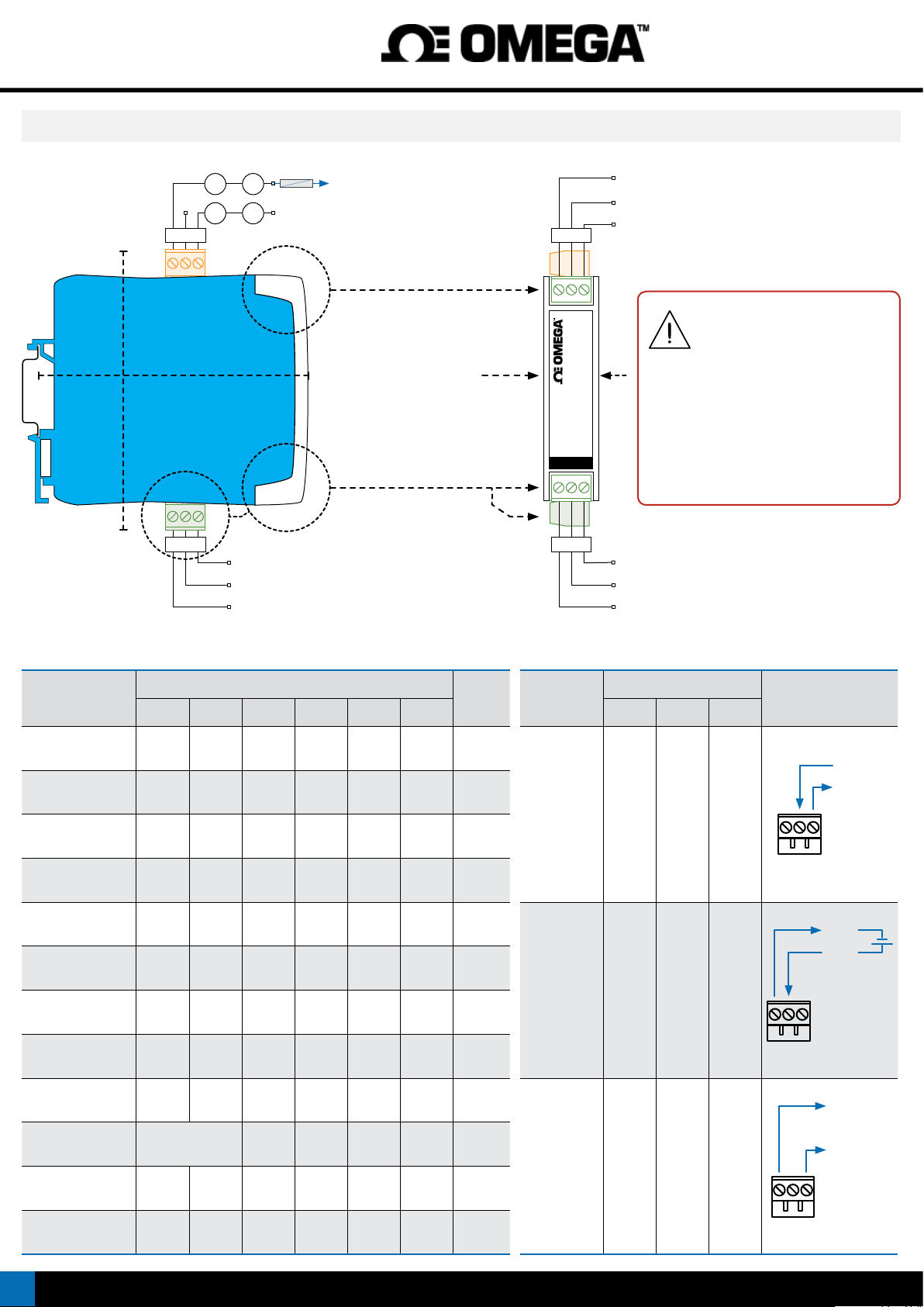
6. Connections and dimensions (mm (inch))
108 mm
(4.25’’)
Standard (35 mm) DIN
rail mount
A B C
1 2 3
~ +
fuse
POWER (ABC)
18 to 265 Vac/dc isolated
~ -
OUTPUT SIGNAL (789)
see ‘Table 3’
106 mm
(4.17’’)
INPUT SIGNAL (123 456)
see
‘Table 2’
Pt+, Ni+, Ntc+, Resistance+
Thermocouple +, Pt100 3rd wire
Thermocouple -, Pt-, Ni-, Ntc-, Resistance-
22.5mm
(0.89’’)
7 8 9
DR-I3P
4 5 6
Common 0V (or passive mA current output)
Signal 4/20 mA (mA current return)
Signal 0/10 Vdc (or active mA current output)
Fuse - This instrument does not
include internal protection fuse.
According to security regulation
61010-1, add a protection fuse to the power
line to act as a disconnection element, easily
accessible to the operator and identied as
a protection device. Use time-lag fuse, with
value :
• 250 mA, for voltages > 50 Vac/dc
• 400 mA, for voltages < 50 Vac/dc
Vexc (+15 Vdc), Pot.+ (5 Vdc)
mA, Vdc, Potentiometer
Common, Pot.-
Table 2 | INPUT signal connections
INPUT
signal
4/20 mA passive mA- Vexc
4/20 mA active mA- mA+
0/10 Vdc common +Vdc
0/10 Vdc
with Vexc
Potentiometer Pot.- Signal Pot.+
Resistance Res- Res+
NTC NTC- NTC+
Thermocouple tc- tc+
Pt100 (3 wires) Pt-
1 2 3 4 5 6
(3rd wire)
Input terminals Section
common +Vdc Vexc
Pt-
Pt+
...
9.1
9.1
9.1
9.1
9.2
9.3
9.4
9.5
9.6
Table 3 | OUTPUT signal connections
OUTPUT
signal
4/20 mA
active
4/20 mA
passive
Output terminals Connections
7 8 9
mA-
(in)
mA+
(out)
mA-
(in)
mAmA+
mA+
(out)
789
mA+
mA-
789
common
Pt100 (2 wires)
Pt1000, Pt500 Pt- Pt+
Ni100, Ni500,
Ni1000
6
Pt-
(shortcircuit 1 and 2)
Ni- Ni+
Pt+
9.6
9.6
9.6
+Vdc
0/10 Vdc common +Vdc
789
Page 7
DR-I3P isolated signal converter Instruction Manual
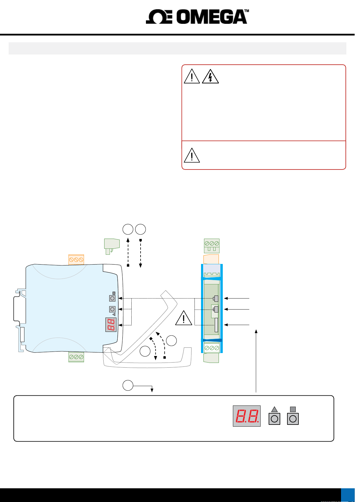
7. Access the ‘Conguration system’
ACCESS THE ‘CONFIGURATION SYSTEM’
1. Remove the output signal terminal
• make sure that there are no dangerous voltages at the input signal
terminals (in case of doubt, remove also the two input signal terminals)
2. Open the front cover
3. Congure the instrument
• locate the ‘conguration digits’
• locate the ‘UP’ (5) and ‘SQ’ (<) keys
BLOCK ACCESS TO THE ‘CONFIGURATION SYSTEM’
4. Close the front cover
• remove the output signal terminal (if it was placed)
5. Connect the output signal terminal
• when connected at place, check that the front cover can not be
opened
• if they were removed, connect the two input signal terminals
51
Opening the front cover reduces the security level of
the operator. If dangerous voltages are connected to
the input terminals, remove both input signal terminals
before opening the front cover. When front cover is open :
• the isolation between accessible parts and power supply is reduced to
‘basic’ level.
• the isolation between accessible parts and input signals is temporarily
disabled.
Operations must be performed by qualied operators.
When correctly connected, the output signal terminal prevents
the front cover from opening.
UP SQ
4
2
3
‘CONFIGURATION SYSTEM’
• the ‘conguration digits’ indicate the active input signal range (see section 5)
• keys ‘UP’ (5) and ‘SQ’ (<) to congure the instrument (see section 8.2)
• the decimal point position indicates the active output signal range (see section 8.3)
Key ‘SQ’ (<)
Key ‘UP’ (5)
‘Conguration digits’
UP SQ
‘Conguration digits’
7
Page 8
DR-I3P isolated signal converter Instruction Manual
8. Conguration system
CONFIGURATION SYSTEM
The DR-I3P isolated signal converter provides a fast and easy
conguration system, based on function codes. Conguration is done
through an internal key pad, accessible behind the front cover.
‘CONFIGURATION DIGITS’
The instrument provides two numerical leds, to inform about the actual
state of the instrument, active input and output signal ranges, and error
codes (see section 11).
CONFIGURATION KEYS
The conguration keys are located inside the instrument, behind the
removable front cover. To access the conguration keys, remove the
output signal terminal, and open the front cover (see section 7). The
instrument allows to block the key functions, by activating an access
code (‘password’ function) (see section 8.5).
8.1. ‘Normal mode’ of operation
‘NORMAL MODE’
When the power supply is connected, the instrument:
• activates the ‘conguration digits’, and displays the code for the actual
input signal range (see section 5)
• activates the decimal point (ash), showing the actual output signal
range (see section 8.3)
• the instrument is in ‘normal mode’ of operation
8.2. ‘Conguration mode’
HOW TO ACCESS THE ‘CONFIGURATION MODE’
With the instrument in ‘normal mode’ of operation (see section 8.1),
press for 1 second the ‘SQ’ (<) key. The horizontal leds lights from
bottom to top. When the upper led lights, the instrument activates the
‘conguration mode’.
If the key is released before activating the ‘conguration mode’,
the horizontal leds light downwards from top to bottom, and
the instrument returns to ‘normal mode’ of operation.
Inside the ‘conguration mode’ the decimal point is not active.
Inside the ‘conguration mode’, the ‘conguration digits’ display
the code of the active input signal range (see section 5). Press the ‘UP’
(5) key to increase the code.
• press once to increase the value in +1
• maintain the key pressed to automatically increase the value
When the desired code is reached, press the ‘SQ’ (<) key. The leds light
a round shape while new conguration is stored, and the instrument
returns to ‘normal mode’ of operation.
When exiting the ‘conguration mode’ without changes (‘rollback’
activation, selection of ‘inactive codes’, etc), the horizontal leds
light down from top to bottom, and the instrument returns to
‘normal mode’ of operation.
‘ROLLBACK’ FUNCTION
If there is no interaction from the operator for 30 seconds, the instrument
exits the ‘conguration mode’ and returns to ‘normal mode’ of operation,
discarding changes.
HOW TO ACCESS THE ‘CONFIGURATION MODE’ AND THE ‘TOOLS’ MENU
With the instrument in ‘normal mode’ of operation, there is access to the
‘conguration mode’ and the ‘tools’ menu.
• to access the ‘conguration mode’, press the ‘SQ’ (<) key for 1 second
(see section 8.2)
• to access the ‘tools’ menu, press the ‘UP’ (5) key for 1 second (see
section 8.4)
‘ECO’ FUNCTION (‘CONFIGURATION DIGITS’ ARE AUTOMATICALLY
POWERED OFF)
If there is no interaction from the operator for 60 seconds, the instrument
powers off the ‘conguration digits’. The decimal point remains active
(ashing), indicating that the instrument is working correctly.
HOW TO POWER ON THE ‘CONFIGURATION DIGITS’
To power on the ‘conguration digits’, press one of the front keys ‘SQ’
(<) or ‘UP’ (5). This will power on the ‘conguration digits’, and activate
the ‘normal mode’ of operation.
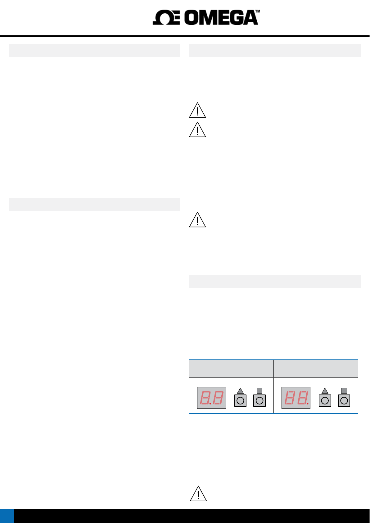
8.3. Output 4/20 mA and 0/10 Vdc
OUTPUT 4/20 mA AND 0/10 Vdc
The DR-I3P instrument can be congured for 4/20 mA or 0/10 Vdc
output signal. The congured output signal is identied with the active
decimal point at the ‘conguration digits’.
• active decimal point to the right, for 4/20 mA output
• active decimal point to the left, for 0/10 Vdc output
Table 4 | Decimal point indicates the active output signal
Output 0/10 Vdc
(decimal point to the left)
UP SQ UP SQ
HOW TO CONFIGURE THE OUTPUT SIGNAL TO 4/20 mA AND 0/10 Vdc
With the instrument in ‘normal mode’ of operation, press the ‘SQ’ (<)
key and the ‘UP’ (5) key at the same time. The horizontal leds lights
from bottom to top. When the upper led lights, the actual decimal point
position is displayed. After 1 second, the new decimal point position
activates. Release the two keys, and the leds light a round shape while
the new conguration is stored, and the instrument returns to ‘normal
mode’ of operation.
Connect the output terminals according to the output signal
congured (see section 6).
Output 4/20 mA
(decimal point to the right)
8
Page 9
DR-I3P isolated signal converter Instruction Manual
8.4. ‘Tools’ menu
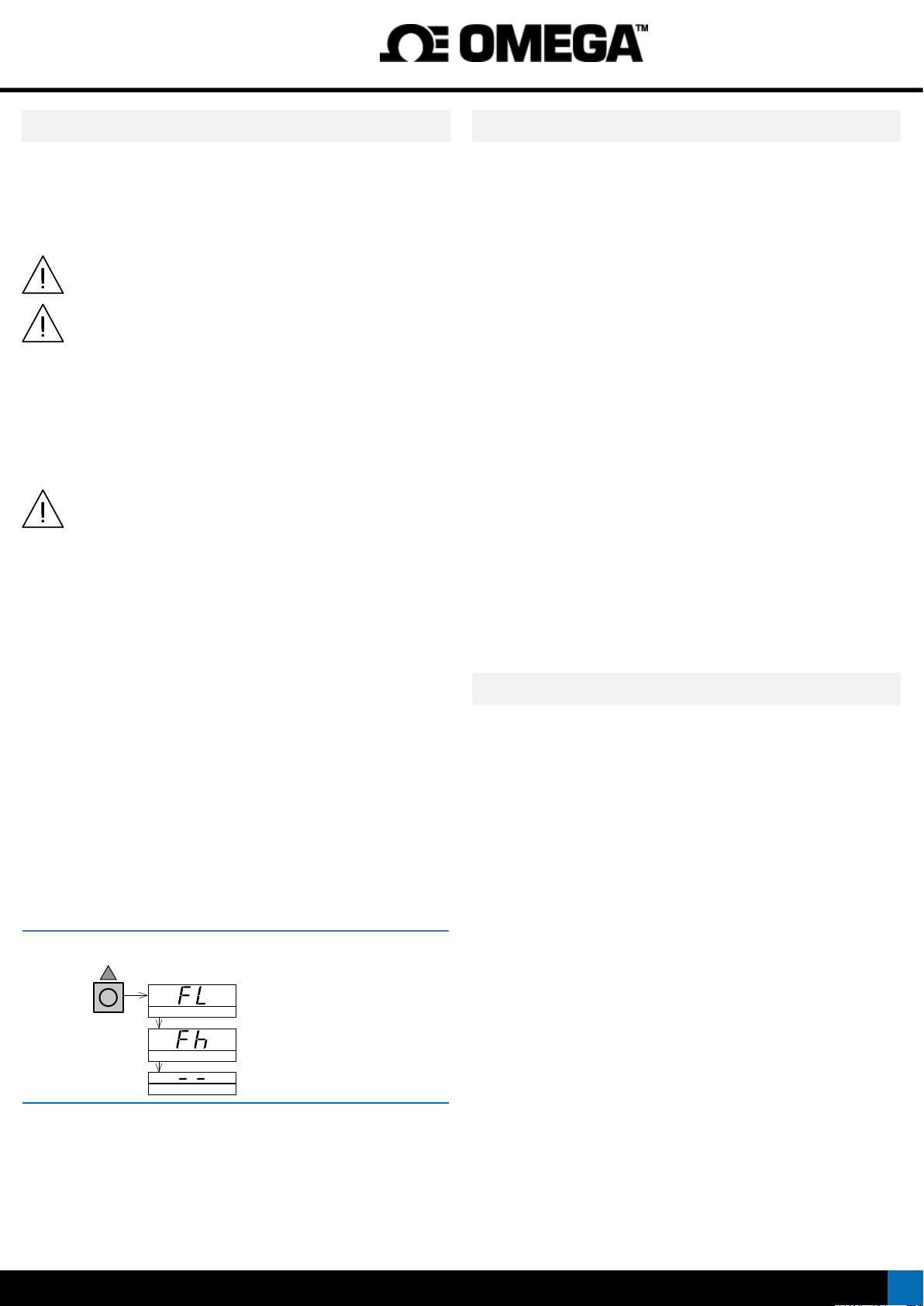
HOW TO ACCESS THE ‘TOOLS’ MENU
With the instrument in ‘normal mode’ of operation (see section 8.1), press
for 1 second the ‘UP’ (5) key. The horizontal leds lights from bottom to
top. When the upper led lights, the instrument activates the ‘tools’ menu.
If the key is released before activating the ‘tools’ menu, the horizontal
leds light downwards from top to bottom, and the instrument
returns to ‘normal mode’ of operation.
Inside the ‘tools’ menu, the decimal point is not active.
Inside the ‘tools’ menu, the ‘conguration digits’ indicate the
code of the rst function available.
• press the ‘UP’ (5) key to move to the next function.
• press the ‘SQ’ (<) key to activate the selected function.
To exit the ‘tools’ menu, press the ‘UP’ (5) key until the parameter
‘- -’ appears, and press the ‘SQ’ (<) key (or wait 30 seconds without
pressing any key to wait for the automatic ‘rollback’).
When exiting the ‘tools’ menu, the horizontal leds light down from top
to bottom, and the instrument returns to ‘normal mode’ of
operation.
‘ROLLBACK’ FUNCTION
If there is no interaction from the operator for 30 seconds, the instrument
exits the ‘tools’ menu and returns to ‘normal mode’ of operation.
8.5. Conguration block (‘password’)
HOW TO BLOCK ACCESS TO ‘CONFIGURATION MODE’ (‘PASSWORD’)
Dene a ‘password’ code to prevent access to ‘conguration mode’ and
to ‘tools’ menu to unauthorized operators. The ‘password’ code will be
requested when any key is pressed.
To activate a ‘password’ select code ‘95’ inside the ‘conguration mode’.
The step-by-step process is indicated below.:
• access the ‘conguration mode’ (see section 8.2)
• access code ‘95’
• press the ‘SQ’ (<) key to select
• the ‘conguration digits’ indicate code ‘00’ ashing
• press the ‘UP’ (5) key to select the desired code (for example ‘73’)
• press the ‘SQ’ (<) key to validate or wait for the automatic ‘rollback’
(30 seconds) to exit without changes
• the menu returns ‘normal mode’ (see section 8.1)
Once the ‘password’ code is applied, when a key is pressed, the
‘conguration digits’ indicate code ‘00’ ashing. enter the ‘password’
code to unlock access (code ‘73’ in the previous example).
HOW TO DEACTIVATE THE ‘PASSWORD’
To deactivate the ‘password’, access again to code ‘95’ and select value
‘00’. Exit validating changes.
AVAILABLE FUNCTIONS
The ‘Force Low’ (‘FL’) and ‘Force High’ (‘Fh’) functions allow to temporarily
force the output signal to the low and high levels of the actual output
signal range selected. These tools allow to easily validate the correct
function of the remote elements connected to the instrument output
• select ‘Force Low’ (‘FL’) function to set the output signal to the minimum
value of the selected range (4 mA or 0 Vdc). The ‘FL’ ash message
indicates that the function is active. Press any key to deactivate and
return to the ‘Force Low’ (‘FL’) menu entry.
• select ‘Force High’ (‘Fh’) function to set the output signal to the
maximum value of the selected range (20 mA or 10 Vdc). The ‘Fh’
ash message indicates that the function is active. Press any key to
deactivate and return to the ‘Force High’ (‘Fh’) menu entry.
Table 5 | ‘Tools’ menu
UP
Press ‘UP’ (5) for 1 second to access the
‘tools’ menu.
‘Force Low’
‘Force high’
Exit
8.6. Pt100 ‘alpha’ parameter
‘ALPHA ‘ VALUE ‘385’ OR ‘390’
The instrument can be congured to read Pt probes using ‘alpha’
parameter set to ‘0.0385’ (default value) or ‘0.0390’. This parameter is a
specication of the Pt probe (Pt100, Pt500, Pt1000) and depends on the
probe manufacturer.
HOW TO SET THE ‘ALPHA’ PARAMETER
To congure the ‘alpha’ value, access code ‘96’ inside the ‘conguration
mode’. The step-by-step process is indicated below.
• access the ‘conguration mode’ (see section 8.2)
• access code ‘96’
• press the ‘SQ’ (<) key to select
• the ‘conguration digits’ indicate code ‘01’ ashing
• press the ‘UP’ (5) key, to select value ‘01’ for ‘alpha’ value of ‘0.0385’
or select ‘02’ for ‘alpha’ value of ‘0.0390’
• press the ‘SQ’ (<) key to validate or wait for the automatic ‘rollback’
(30 seconds) to exit without changes
• the menu returns ‘normal mode’ (see section 8.1)
9
Page 10
DR-I3P isolated signal converter Instruction Manual
9. Input signals
9.1. Process
MEASURING RANGES FOR PROCESS SIGNALS
The instrument can be congured to measure process
Process
To activate the desired input signal range, activate the range code (see
Table 7) into ‘conguration mode’ (see section 8.2).
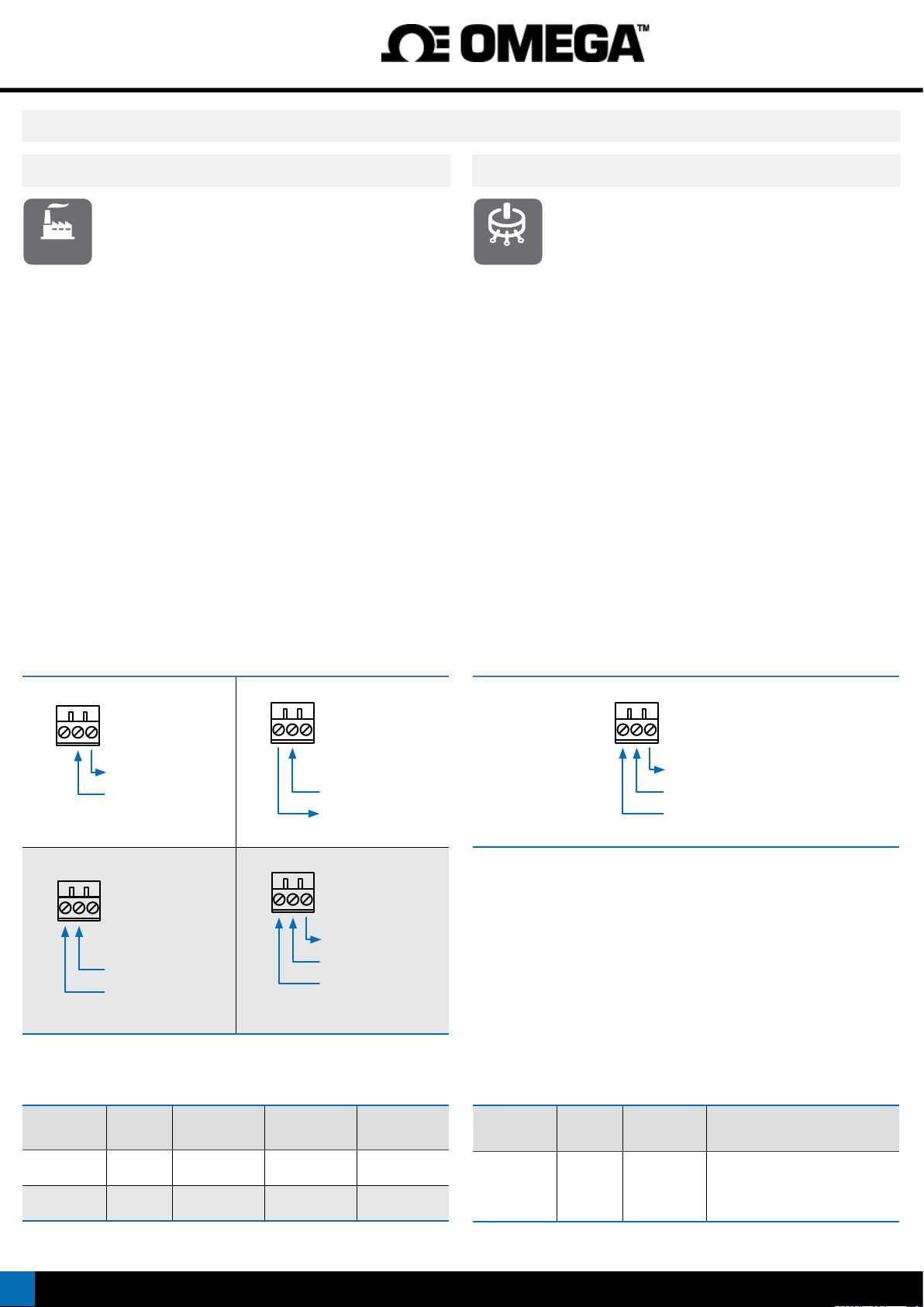
See connection examples at ‘Table 6’.
OUTPUT SIGNAL
the output signal is congurable to 4/20 mA (active and passive) and
0/10 Vdc (see section 8.3).
MAXIMUM OVERSIGNAL
‘Maximum oversignal’ is the maximum signal accepted by the instrument.
Higher signal values may cause instrument damage. Lower values are
non destructive but may be out of accuracy specications.
EXCITATION VOLTAGE (VEXC)
The instrument provides +15 Vdc excitation voltage at terminal ‘6’. This
excitation voltage is provided to power up the transducer that generates
the signal, up to a maximum of 30 mA.
signals in 4/20 mA (active and passive) and 0/10 Vdc.
The instrument provides excitation voltage to power up
transducers when necessary.
9.2. Potentiometers
MEASURING RANGES FOR POTENTIOMETERS
The instrument can be congured to measure
Potentiometer
To activate the desired input signal range, activate the range code (see
Table 9) into ‘conguration mode’ (see section 8.2).
See connection examples at ‘Table 8’.
OUTPUT SIGNAL
the output signal is congurable to 4/20 mA (active and passive) and
0/10 Vdc (see section 8.3).
EXCITATION VOLTAGE (Vexc)
The instrument provides +5 Vdc excitation voltage at terminal ‘6’. The
excitation voltage is automatically congured when a potentiometer
code is selected (see Table 9).
potentiometers (3 wires), with nominal value higher than
500 Ohms and below 20 KOhms.
Table 6 | Connection examples for process signals
456
mA+
(+15 Vexc)
456
mA-
Signal 4/20 mA (passive)
456
Signal 4/20 mA (active)
456
+Vdc
común
Signal 0/10 Vdc
Table 7 | Input ranges for process signals
with excitation voltage
mAmA+
+15 Vexc
común
+Vdc
Signal 0/10 Vdc
Table 8 | Connection examples for potentiometers
456
Pot+
(+5 Vdc)
Señal
Pot- (común)
Table 9 | Input ranges for potentiometer signals
Input signal Code Accuracy
(% FS)
4/20 mA 10 <0.30 % 25 mA
0/10 Vdc 11 <0.30 % 25 Vdc 1 MOhm
10
Max.
overvoltage
Zin
<1.2 Vdc voltage
drop on terminals
Input signal Code Accuracy
(% FS)
0/100 % 12 <1.0 %
Potentiometers
accepted
from 0/500 Ohms
up to 0/20 KOhms
Page 11
DR-I3P isolated signal converter Instruction Manual
9 Input signals (cont.)
9.3. Resistances
MEASURING RANGES FOR RESISTANCES
The instrument can be congured to measure resistance
Resistances
range code (see Table 11) into ‘conguration mode’ (see section 8.2).
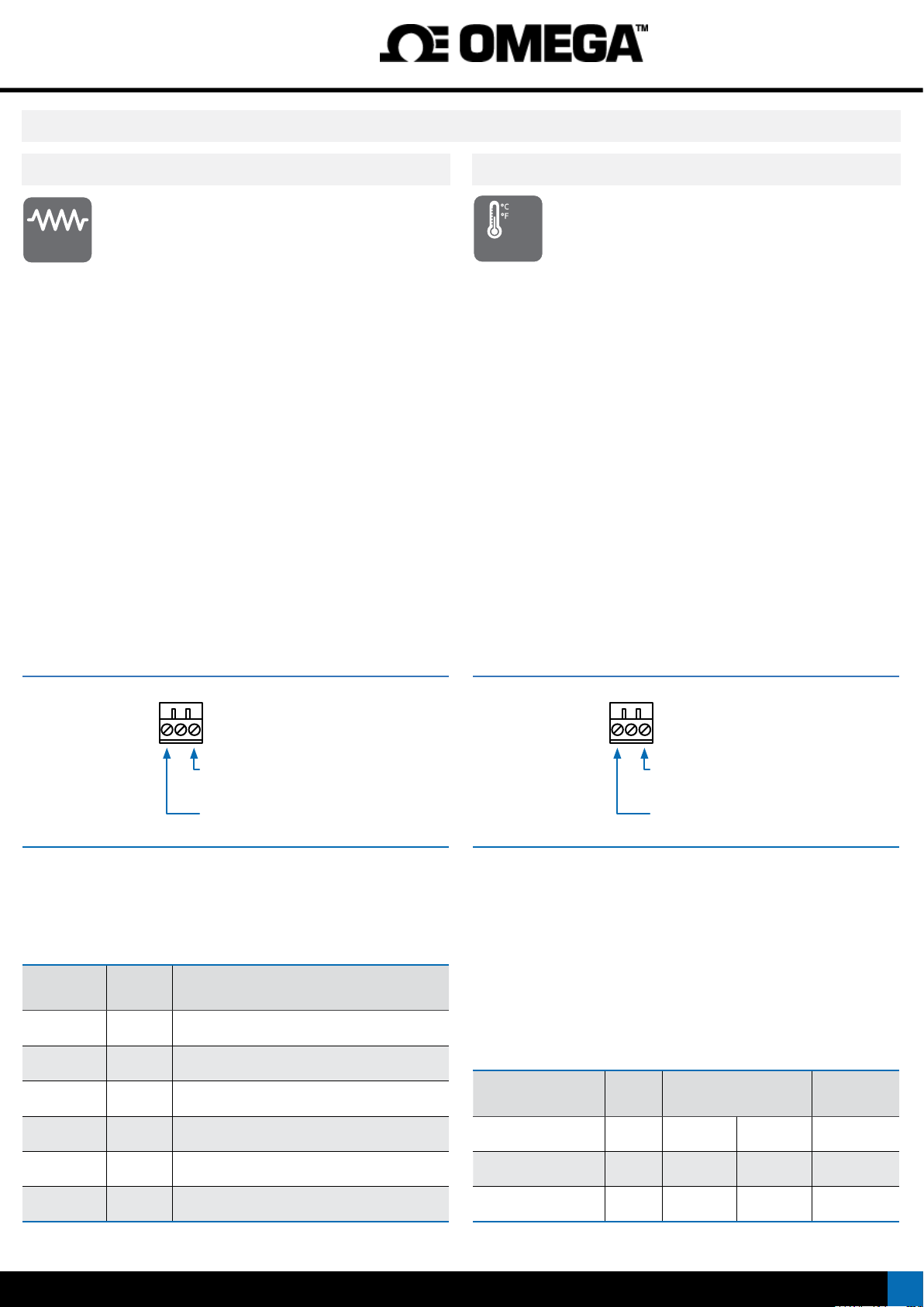
See connection examples at ‘Table 10’.
OUTPUT SIGNAL
the output signal is congurable to 4/20 mA (active and passive) and
0/10 Vdc (see section 8.3).
signals. Measurement uses 2 wires.
To activate the desired input signal range, activate the
9.4. NTC probes
NTC PROBES ACCEPTED
NTC
The instrument can be congured to measure temperature
Temperature
types 44006.
To activate the desired input signal range, activate the range code (see
Table 13) into ‘conguration mode’ (see section 8.2).
See connection examples at ‘Table 12’.
OUTPUT SIGNAL
the output signal is congurable to 4/20 mA (active and passive) and
0/10 Vdc (see section 8.3).
SENSOR BREAK DETECTION
The instrument displays an error message in case of sensor break (see
section 11).
from common NTC probes.
Accepts NTC probes with R
=10K and β=3500 and NTC
25
Table 10 | Connection examples for resistances
123
res+
res-
Table 11 | Input ranges for resistances
Input signal Code Accuracy (% FS)
0/100 KOhm 13 <1.0 % FS
0/50 KOhm 14 <1.5 % FS
0/25 KOhm 15 <2.0 % FS
Table 12 | Connection examples for NTC probes
123
NTC+
NTC-
Connections for NTC
Table 13 | Temperature ranges for NTC probes
Input signal Code Measurement range Total error
0/10 KOhm 16 <1.0 % FS
0/5 KOhm 17 <1.5 % FS
0/2.5 KOhm 18 <1.0 % FS
(R25=10K y β=3500)
NTC
NTC (44006) 82 -60/90 ºC -76/194 ºF <1.0 % FS
NTC (44006) 83 0/90 ºC 32/194 ºF <1.5 % FS
81 -60/90 ºC -76/194 ºF <1.0 % FS
11
Page 12
DR-I3P isolated signal converter Instruction Manual
9 Input signals (cont.)
9.5. Thermocouples
MEASURING RANGES FOR THERMOCOUPLES
tc
The instrument can be congured to measure temperature
Temperature
To activate the desired thermocouple type and measurement range,
activate the range code (see ‘Table 15’ up to ‘Table 21’) into ‘conguration
mode’ (see section 8.2).
See connection examples at ‘Table 14’.
OUTPUT SIGNAL
the output signal is congurable to 4/20 mA (active and passive) and
0/10 Vdc (see section 8.3).
SENSOR BREAK DETECTION
The instrument displays an error message in case of sensor break (see
section 11).
TOTAL ERROR
The ‘total error’ indicated in the tables below, includes the measuring
error, the cold junction error and the output signal error.
Table 14 | Connections for thermocouples
Table 15 | Temperature ranges for thermocouple J
Input signal Code Measurement range Total error
from thermocouple probes, types J, K, N, E, T, R and S. The
instrument automatically compensates the cold junction.
123
For a correct measure of
thermocouple signals,
!
always use compensated
cable between the instrument and the
tc+
thermocouple.
tc-
(cold junction included)
*
19 0/1200 ºC
20 0/1000 ºC 32/1832 ºF <0.5% FS
32/2190 ºF
*
<0.5% FS
Table 17 | Temperature ranges for thermocouple N
Input signal Code Measurement range Total error
*
*
*
32/2372 ºF
32/1472 ºF
32/752 ºF
33 0/1300 ºC
34 0/1000 ºC 32/1832 ºF <0.5% FS
35 0/800 ºC 32/1472 ºF <0.7% FS
Thermoc. N
Table 18 | Temperature ranges for thermocouple E
Input signal Code Measurement range Total error
Thermoc. E
Table 19 | Temperature ranges for thermocouple T
Input signal Code Measurement range Total error
Thermoc. T
36 0/600 ºC 32/1112 ºF <1.0% FS
37 0/450 ºC 32/842 ºF <2.0% FS
38 0/300 ºC 32/572 ºF <3.0% FS
39 0/150 ºC 32/302 ºF <5.0% FS
41 0/900 ºC
42 0/600 ºC 32/1112 ºF <0.5% FS
43 0/450 ºC 32/842 ºF <1.0% FS
44 0/300 ºC 32/572 ºF <1.5% FS
45 0/150 ºC 32/302 ºF <3.0% FS
46 0/400 ºC
47 0/300 ºC 32/572 ºF <1.3% FS
48 0/200 ºC 32/392 ºF <2.0% FS
49 0/100 ºC 32/212 ºF <4.0% FS
(cold junction included)
*
<0.5% FS
(cold junction included)
*
<0.5% FS
(cold junction included)
*
<1.0% FS
21 0/800 ºC 32/1472 ºF <0.5% FS
Thermoc. J
Table 16 | Temperature ranges for thermocouple K
Input signal Code Measurement range Total error
Thermoc. K
12
22 0/600 ºC 32/1112 ºF <0.7% FS
23 0/450 ºC 32/842 ºF <1.0% FS
24 0/300 ºC 32/572 ºF <2.0% FS
25 0/150 ºC 32/302 ºF <3.0% FS
(cold junction included)
*
26 0/1350 ºC
27 0/1000 ºC 32/1832 ºF <0.5% FS
28 0/800 ºC 32/1472 ºF <0.5% FS
29 0/600 ºC 32/1112 ºF <0.7% FS
30 0/450 ºC 32/842 ºF <1.5% FS
31 0/300 ºC 32/572 ºF <2.5% FS
32 0/150 ºC 32/302 ºF <4.5% FS
32/2462 ºF
*
<0.5% FS
Table 20 | Temperature ranges for thermocouple R
Input signal Code Measurement range Total error
50 0/1750 ºC
51 0/1500 ºC 32/2732 ºF <1.5% FS
Thermoc. R
52 0/1200 ºC 32/2192 ºF <1.8% FS
53 0/900 ºC 32/1652 ºF <2.0% FS
Table 21 | Temperature ranges for thermocouple S
Input signal Code Measurement range Total error
54 0/1750 ºC
55 0/1500 ºC 32/2732 ºF <1.5% FS
Thermoc. S
56 0/1200 ºC 32/2192 ºF <1.8% FS
57 0/900 ºC 32/1652 ºF <2.0% FS
*
*
32/3182 ºF
32/3182 ºF
(cold junction included)
*
<1.3% FS
(cold junction included)
*
<1.3% FS
Page 13
DR-I3P isolated signal converter Instruction Manual
9 Input signals (cont.)
9.6. Pt (Pt100, Pt500, Pt1000) and Ni (Ni100, Ni1000) probes
MEASURING RANGES FOR PT AND NI PROBES
Pt
The instrument can be congured to measure temperature
Temperature
from Pt probes (Pt100, Pt500 and Pt1000) and Ni probes
(Ni100 y Ni1000).
To activate the desired probe type and measurement range, activate the
range code (see ‘Table 23’ and ‘Table 24’) into ‘conguration mode’ (see
section 8.2).
See connection examples at ‘Table 22’.
OUTPUT SIGNAL
the output signal is congurable to 4/20 mA (active and passive) and
0/10 Vdc (see section 8.3).
SENSOR BREAK DETECTION
The instrument displays an error message in case of of sensor break
(see section 11).
PT100 WITH 2 AND 3 WIRES
The instrument accepts 2 and 3 wire Pt100 probes. Select the connection
according to the wires of the probes (see Table 22).
‘ALPHA’ TEMPERATURE COEFFICIENT
The instrument is congured ‘by default’ to work with an ‘alpha’ value of
‘0.0385’ for Pt proves (Pt100, Pt500, Pt1000). To activate an ‘alpha’ value
of ‘0.0390’ see section ‘8.6’. This parameter is associated to the probe
and depends on the probe manufacturer.
Table 23 | Temperature ranges for Pt100
Input signal Code Measurement range
59 0/700 ºC
60 0/600 ºC 32/1112 ºF <0.3% FS
61 0/500 ºC 32/932 ºF <0.4% FS
62 0/400 ºC 32/752 ºF <0.5% FS
63 0/300 ºC 32/572 ºF <0.6% FS
Pt100
64 0/200 ºC 32/392 ºF <0.7% FS
65 0/100 ºC 32/121 ºF <0.8% FS
66 -50/+50 ºC -58/122 ºF <1.0% FS
67 -100/+100 ºC -148/212 ºF <0.5% FS
68 -200/+200 ºC
(* FS for accuracy calculation)
*
32/1292 ºF
*
-328/392 ºF
*
*
Total error
<0.3% FS
<0.5% FS
CURRENT THROUGH THE PROBE
The instrument generates <900 uA through Pt100 and Ni100 probes. The
instrument generates <90 uA through Pt500, Pt1000 and Ni1000 probes.
Table 22 | Connection examples for Pt100 3 wires and Pt, Ni 2 wires
123
Pt100+
Pt100- (3
rd
wire)
Pt100-
Connections for Pt100 (3 wires)
123
Pt100+
shortcircuit 1-2
Pt100-
Connections for Pt100 (2 wires)
123
Table 24 | Temperature ranges for Pt500, Pt1000 and Ni
Input signal Code Measurement range
69 0/630 ºC
Pt500
Pt1000
70 0/300 ºC 32/572 ºF <1.0% FS
71 -150/150 ºC -238/302 ºF <1.0% FS
72 0/630 ºC
73 0/300 ºC 32/572 ºF <1.5% FS
74 -150/150 ºC -238/302ºF <1.5% FS
(* FS for accuracy calculation)
*
32/1166 ºF
*
32/1166 ºF
*
*
Total error
<1.0% FS
<1.0% FS
Pt+, Ni+
Pt-, Ni-
Connections for Pt500, Pt1000, Ni,100 and Ni1000 (2 wires)
Ni100 75 -60/180 ºC -76/356 ºF <1.0% FS
--- 76 --- ---
Ni1000 77 -60/180 ºC -76/356 ºF <1.0% FS
---
13
Page 14
DR-I3P isolated signal converter Instruction Manual
10. Technical specications
INPUT SIGNAL RANGES
process 4/20 mA, 0/10 Vdc (active and passive)
excitation voltage +15 Vdc @30 mA
(see section 9.1)
thermocouples J, K, N, E, T, R and S
(see section 9.5)
‘Pt’ and ‘Ni’ probes Pt100 (2 and 3 wires, automatic compensation
up to 30 Ohm)
Pt500, Pt1000, Ni100, Ni1000 (2 wires)
(see section 9.6)
‘NTC’ probes
resistances ranges for 100 K, 50 K, 25 K, 10 K, 5 K y 2.5 K
potentiometers nominal value form 500 Ohm to 20 KOhm
ACCURACY AT 25 ºC see section for each type of signal
THERMAL DRIFT 150 ppm/º
STEP RESPONSE 300 mSec. (0 % to 99 % signal)
OUTPUT SIGNAL RANGES
active mA signal 4/20 mA active, max. 22 mA, min. 1.5 mA,
passive mA signal 4/20 mA passive, max. 30 Vdc on terminals
Vdc ranges 0/10 Vdc, max. 11 Vdc, min.. -1 Vdc, minimum
CONFIGURATION
key pad 2 keys
display 2 digits, 7 segments, 5 mm height, red color
POWER SUPPLY
voltage range 18 to 265 Vac/dc isolated
AC frequency 45 to 65 Hz
consumption <1.5 W
power wires 1 mm
overvoltage category 2
ISOLATION
input - output 2300 Veff (60 seconds)
power - input 2300 Veff (60 seconds)
power - output 2300 Veff (60 seconds)
IP PROTECTION IP30
IMPACT PROTECTION IK06
TEMPERATURE
operation de 0 a +50 ºC
storage de -20 a +70 ºC
‘warm-up’ time 15 minutes
MECHANICAL
size 106 x 108 x 22.5 mm
mounting standard DIN rail (35 x 7.5 mm)
connections
housing material polyamide V0
weight <150 grams
packaging 120 x 115 x 30 mm, cardboard
(see section 9.4)
(see section 9.3)
(see section 9.2)
maximum load < 400 Ohm
load > 1 KOhm
(20 to 240 Vac/dc ±10%)
2
to 2.5 mm2 (AWG17 to AWG14)
plug-in screw terminal
(pitch 5.08 mm)
11. Error codes
In case of error, the error code is shown ashing on the ‘conguration
digits’. The error code is not visible inside ‘conguration mode’ or inside
the ‘tools’ menu.
The error code remains active on display until the problem that caused
the error is solved. In case of multiple error codes, solve the rst problem
to see the next active error code.
Table 25 | Error codes
‘Hardware underrange’.
E1
Input signal is below the minimum readable signal. Output signal is
the minimum available 0 Vdc, 0 mA. Possible sensor break.
‘Hardware overrrange’.
E2
Input signal is above the maximum readable signal. Output signal is
the maximum available 10.5 Vdc, 20.5 mA. Possible sensor break.
‘Password error’.
E3
If ‘password’ function is active, the password code entered is not
correct.
12. Factory default parameters
Input signal 4/20 mA [‘10’]
Output signal 4/20 mA [‘xx.’]
Password code disabled [‘00’]
Pt100 ‘alpha’ 0.0385 [‘01’]
Display code [‘10.’]
RESET TO DEFAULT FACTORY PARAMETERS
To recover the instrument to default factory parameters, select code ‘97’
and activate value ‘01’.
• access the ‘conguration mode’
• access code ‘97’ and press key ‘SQ’ (<)
• the ‘conguration digits’ show code ‘00’ ashing
• press key ‘UP’ (5) to change to value ‘01’
• press key ‘SQ’ (<)
• the leds light a round shape while the new conguration is stored, and
the instrument returns to ‘normal mode’ of operation
• the ‘conguration digits’ show code ‘10.’ and the default factory
conguration is now active
FIRMWARE VERSION
The instrument ‘rmware’ version is an alphanumerical code from ‘00’ to
‘FF’, accessible through the conguration code ‘98’.
14
Page 15
DR-I3P isolated signal converter Instruction Manual
13. Precautions on installation
Risk of electrical shock. Instrument terminals can be
connected to dangerous voltage.
Instrument protected with double isolation. No earth
connection required.
Instrument conforms to CE rules and regulations.
This instrument has been designed and veried conforming to the
61010-1 CE Security Regulation, for industrial applications. Installation
of this instrument must be performed by qualied personnel only. This
manual contains the appropriate information for the installation. Using
the instrument in ways not specied by the manufacturer may lead to a
reduction of the specied protection level. Disconnect the instrument
from all external circuits before starting any maintenance and / or
installation action.
The instrument does not have a general switch and will start operation
as soon as power is connected. The instrument does not have protection
fuse, the fuse must be added during installation.
The instrument is designed to be DIN rail mounted, inside a cabinet,
protected from direct impacts. An appropriate ventilation of the
instrument must be assured. Do not expose the instrument to excess of
humidity. Maintain clean by using a humid rag and do NOT use abrasive
products such as alcohols, solvents, etc. General recommendations for
electrical installations apply, and for proper functionality we recommend
: if possible, install the instrument far from electrical noise or magnetic
eld generators such as power relays, electrical motors, speed variators,
... If possible, do not install along the same conduits power cables
(power, motor controllers, electrovalves, ...) together witah signal and/
or control cables. Before proceeding to the power connection, verify
that the voltage level available matches the power levels indicated in
the label on the instrument. In case of re, disconnect the instrument
from the power line, re alarm according to local rules, disconnect the air
conditioning, attack re with carbonic snow, never with water.
15. CE declaration of conformity
Products IDR-I3P
The manufacturer declares that the instruments indicated comply with the
directives and rules indicated below.
Electromagnetic compatibility directive 2014/30/EU
Low voltage directive 2014/35/EU
ROHS directive 2011/65/EU
WEEE directive 2012/19/EU
Security rules EN-61010-1
Instrument Fixed, Permanently connected
Pollution degree 1 and 2 (without condensation)
Isolation Double
Overvoltage category 2
Electromagnetic compatibility rules EN-61326-1
EM environment
Immunity levels
EN-61000-4-2 By contact ±4 KV Criteria A
By air ±8 KV Criteria A
EN-61000-4-3 Criteria A
*use shielded cable for signal and power lines to assure compliance with the rule.
loss of performance of ±5% is admissible without shielded.
EN-61000-4-4 On AC power lines: ±2 KV Criteria B
On DC power lines: ±2 KV Criteria B
On signal lines : ±1 KV Criteria B
EN-61000-4-5
EN-61000-4-6 Criteria A
*maintain signal and control lines below 3 meter length to assure compliance with
the rule.
EN-61000-4-8 30 A/m a 50/60 Hz Criteria A
EN-61000-4-11
40 % 10 cycles Criteria A
70 % 25 cycles Criteria A
0 % 250 cycles Criteria B
Emission levels
CISPR 11 Instrument Class A & Class B Group 1
Industrial & Basic
Between AC power lines ±1 KV
Between DC power lines DC ±1 KV
0 % 1/2 cycle Criteria A
Criteria A
Criteria A
Criteria A
A
Conformity with security regulations EN-61010-1 requires that
the front cover is closed. The output terminal prevents the
front cover from opening.
14. Warranty
This instrument is warranted against all manufacturing defects for a
period of 24 months, as requested by the European legislation. This
warranty does not apply in case of misuse or accident, and the scope
of the warranty is limited to repair of the instrument, not being the
manufacturer responsible for additional damages or additional costs.
Within the warranty period and after examination by the manufacturer,
the unit will be repaired or substituted when found to be defective.
According to directive 2012/19/EU, electronic equipment
must be recycled in a selective and controlled way at the
end of its useful life.
15
Page 16

Where Do I Find Everything I Need for
Process Measurement and Control?
OMEGA…Of Course!
Shop online at omega.com
TEMPERATURE
Thermocouple, RTD & Thermistor Probes, Connectors, Panels & Assemblies
Wire: Thermocouple, RTD & Thermistor
Calibrators & Ice Point References
Recorders, Controllers & Process Monitors
Infrared Pyrometers
PRESSURE, STRAIN AND FORCE
Transducers & Strain Gages
Load Cells & Pressure Gages
Displacement Transducers
Instrumentation & Accessories
FLOW/LEVEL
Rotameters, Gas Mass Flowmeters & Flow Computers
Air Velocity Indicators
Turbine/Paddlewheel Systems
Totalizers & Batch Controllers
pH/CONDUCTIVITY
pH Electrodes, Testers & Accessories
Benchtop/Laboratory Meters
Controllers, Calibrators, Simulators & Pumps
Industrial pH & Conductivity Equipment
DATA ACQUISITION
Communications-Based Acquisition Systems
Data Logging Systems
Wireless Sensors, Transmitters, & Receivers
Signal Conditioners
Data Acquisition Software
HEATERS
Heating Cable
Cartridge & Strip Heaters
Immersion & Band Heaters
Flexible Heaters
Laboratory Heaters
ENVIRONMENTAL
MONITORING AND CONTROL
Metering & Control Instrumentation
Refractometers
Pumps & Tubing
Air, Soil & Water Monitors
Industrial Water & Wastewater Treatment
pH, Conductivity & Dissolved Oxygen Instruments
Mxxxx/xxxx
 Loading...