

Omcan Food Machinery PE-IT-0049-D Installation Manual
Pizza Ovens
Models PE-IT-0024-S, 0048-D, 0049-D, 0049-DD
Instruction Manual
Revised - 11/14/2014
Toll Free: 1-800-465-0234
Fax: 905-607-0234
Email: sales@omcan.com
www.omcan.com

Table of Contents
Model PE-IT-0024-S / Model PE-IT-0048-D
Model PE-IT-0049-D / Model PE-IT-0049-DD
Section
General Information
Safety and Warranty
Technical Specications
Installation
Operation
Maintenance
Troubleshooting
French Instructions
------------------------------------------------------------------------------------------------------------------ 6
------------------------------------------------------------------------------------------------------------- 7 - 13
------------------------------------------------------------------------------------------------------------- 14
------------------------------------------------------------------------------------------------- 3 - 4
------------------------------------------------------------------------------------------------- 4 - 5
--------------------------------------------------------------------------------------------------- 15 - 16
----------------------------------------------------------------------------------------------- 16 - 29
Page
------------------------------------------------------------------------------------------------ 5
Spanish Instructions
Parts Breakdown
Electrical Schematics
Notes
Warranty Registration
----------------------------------------------------------------------------------------------------------------------- 58
-------------------------------------------------------------------------------------------------- 44 - 53
--------------------------------------------------------------------------------------------- 30 - 43
-------------------------------------------------------------------------------------------- 54 - 57
-------------------------------------------------------------------------------------------------- 59
2

General Information
Omcan Manufacturing and Distributing Company Inc. and Food Machinery of America, Inc. dba Omcan
are not responsible for any harm or injury caused due to any person’s improper or negligent use of
this equipment. The product shall only be operated by someone over the age of 18, of sound mind, and
not under the inuence of any drugs or alcohol, who has been trained in the correct operation of this
machine, and is wearing authorized, proper safety clothing. Any modication to the machine voids any
warranty, and may cause harm to individuals using the machine or in the vicinity of the machine while
in operation.
CHECK PACKAGE UPON ARRIVAL
Upon receipt of an Omcan shipment please inspect for external damage. If no damage is evident on the
external packaging, open carton to ensure all ordered items are within the box, and there is no concealed
damage to the machine. If the package has suffered rough handling, bumps or damage (visible or concealed),
please note it on the bill of lading before accepting the delivery and contact Omcan within 24 hours, so we may
initiate a claim with the carrier. A detailed report on the extent of the damage caused to the machine must be
lled out within three days, from the delivery date shown in the shipping documents. Omcan has no recourse
for damaged products that were shipped collect or third party.
Omcan Fabrication et distribution Companie Limité et Food Machinery d’Amerique, dba Omcan ne
sont pas responsables de tout dommage ou blessure causé du fait que toute personne ait utilisé
cet équipement de façon irrégulière. Le produit ne doit être exploité que par quelqu’un de plus de 18
ans, saine d’esprit, et pas sous l’inuence d’une drogue ou d’acohol, qui a été formé pour utiliser
cette machine correctement, et est vêtu de vêtements de sécurité approprié. Toute modication de la
machine annule toute garantie, et peut causer un préjudice à des personnes utilisant la machine ou
des personnes à proximité de la machine pendant son fonctionnement.
VÉRIFIEZ LE COLIS DÈS RÉCEPTION
Dès réception d’une expédition d’Omcan veuillez inspecter pour dommages externes. Si aucun dommage
n’est visible sur l’emballage externe, ouvrez le carton an de s’assurer que tous les éléments commandés
sont dans la boîte, et il n’y a aucun dommage dissimulé à la machine. Si le colis n’a subi aucune mauvaises
manipulations, de bosses ou de dommages (visible ou cachée), notez-le sur le bond de livraison avant
d’accepter la livraison et contactez Omcan dans les 24 heures qui suivent, pour que nous puissions engager
une réclamation auprès du transporteur. Un rapport détaillé sur l’étendue des dommages causés à la machine
doit être rempli dans un délai de trois jours, à compter de la date de livraison indiquée dans les documents
d’expédition. Omcan n’a aucun droit de recours pour les produits endommagés qui ont été expédiées ou cueilli
par un tiers transporteur.
Omcan Empresa De Fabricacion Y Distribucion Inc. Y Maquinaria De Alimentos De America, Inc. dba
Omcan no son responsables de ningun daño o perjuicío causado por cualquier persona inadecuada o
el uso descuidado de este equipo. El producto solo podra ser operado por una persona mayor de 18
años, en su sano juicio y no bajo alguna inuencia de droga o alcohol, y que este ha sido entrenado
en el correcto funcionamiento de esta máquina, y ésta usando ropa apropiada y autorizada. Cualquier
modicación a la máquina anúla la garantía y puede causar daños a las personas usando la máquina
mientras esta en el funcionamiento.
3

General Information
REVISE EL PAQUETE A SU LLEGADA
Tras la recepcion de un envio Omcan favor inspeccionar daños externos. Si no hay daños evidentes en el
empaque exterior, Habra el carton para asegurararse que todos los articulos solicitados ésten dentro de la
caja y no encuentre daños ocultos en la máquina. Si el paquete ha sufrido un manejo de poco cuidado, golpes
o daños (visible o oculto) por favor anote en la factura antes de aceptar la entrega y contacte Omcan dentro
de las 24 horas, de modo que podamos iniciar una reclamación con la compañia. Un informe detallado sobre
los daños causados a la máquina debe ser llenado en el plazo de tres días, desde la fecha de entrega que se
muestra en los documentos de envío. Omcan no tiene ningun recurso por productos dañados que se enviaron
a recoger por terceros.
Safety and Warranty
WARNINGS FOR THE INSTALLER
Check that the location of the oven is in compliance with local and national regulations.
• Adhere to the instructions in this manual.
• Do not execute electrical connections using temporary or uninsulated cables.
• Check that the ground connection of the electrical system is functioning properly.
• Always use individual safety devices and other means of protection in compliance with the law.
WARNING FOR THE USER
The conditions in the surrounding area where the machine will be installed must have the following
characteristics:
• The area must be dry.
• The area must have water and heat sources at an adequate distance.
• Ventilation and lighting must be suitable and comply with the hygiene and safety standards foreseen by
current laws.
• The oor must be at and compact to facilitate thorough cleaning.
• There must be no obstacles of any kind in the immediate vicinity of the machine that could effect the
machine’s normal ventilation.
In addition, the user must:
• Make certain to keep children away from the machine when it is operating.
• Adhere to the instructions in this manual.
• Not remove or tamper with the safety devices on the machine.
• Always pay careful attention to the work at hand and not use the machine when in a distracted state.
• Perform all operations with maximum safety and calm.
• Respect the instructions and warnings displayed on the machine labels.
The labels are accident prevention devices, and therefore must always be perfectly legible. If these should be
4
Safety and Warranty
damaged and illegible, it is mandatory to replace them by requesting replacements from the Manufacturer.
• At the end of each working shift, before cleaning, maintenance or transfer operations, disconnect electrical
power.
WARNINGS FOR THE MAINTENANCE OPERATOR
Observe the instructions indicated in this manual.
• Always use individual safety devices and other protection means.
• Before starting any maintenance operations, make sure that the oven, it was used, is cooled down.
• If any of the safety devices is worn or faulty, the oven is also considered faulty and not to be used.
• Disconnect electrical power before intervening on electrical or electronic parts and connectors.
1 YEAR WARRANTY
WARNING:
The packaging components are classied as normal solid urban waste and can therefore be disposed of
without difculty.
In any case, for suitable recycling, we suggest disposing of the products separately (differentiated
waste) according to the current norms.
DO NOT DISCARD ANY PACKAGING MATERIALS IN THE ENVIRONMENT!
Technical Specications
Model PE-IT-0024-S PE-IT-0048-D PE-IT-0049-D PE-IT-0049-DD
Maximum
Temperature
Electrical 220V/60/3
Power 6.6 kW 13.2 kW 18 kW
Volume 23.7 Cu. Ft. 36.7 Cu. Ft. 48.7 Cu. Ft.
Chamber Dimensions
External Dimensions
Net Weight 115 kg. / 253 lbs. 183 kg. / 403.4 lbs. 231 kg. / 509 lbs.
Gross Weight 132 kg. / 291 lbs. 201 kg. / 443 lbs. 254 kg. / 560 lbs.
27.6” x 27.6” x 5.9”
701 x 701 x 150mm
43” x 39.8” x 16.9”
1092 x 1011 x 429mm
(27.6” x 27.6” x 5.9”) x 2
(701 x 701 x 150mm) x 2
43” x 39.8” x 29.5”
1092 x 1011 x 749mm
842°F / 450°C
(41.3” x 27.6” x 5.9”) x 2
(1049 x 701 x 150mm) x 2
56.9” x 39.8” x 29.5”
1445 x 1011 x 749mm
5
Installation
Installation must be executed by qualied personnel in compliance with local and national regulations.
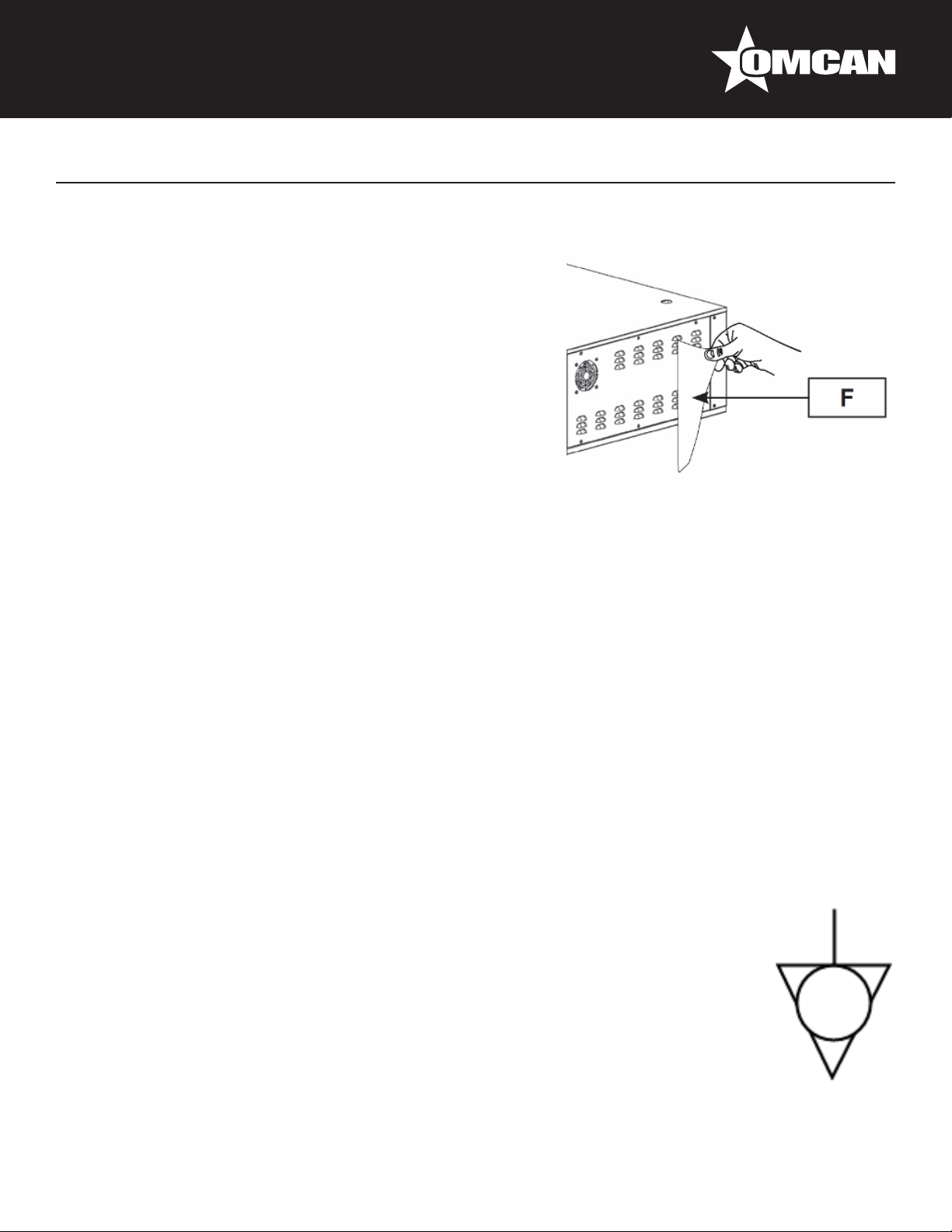
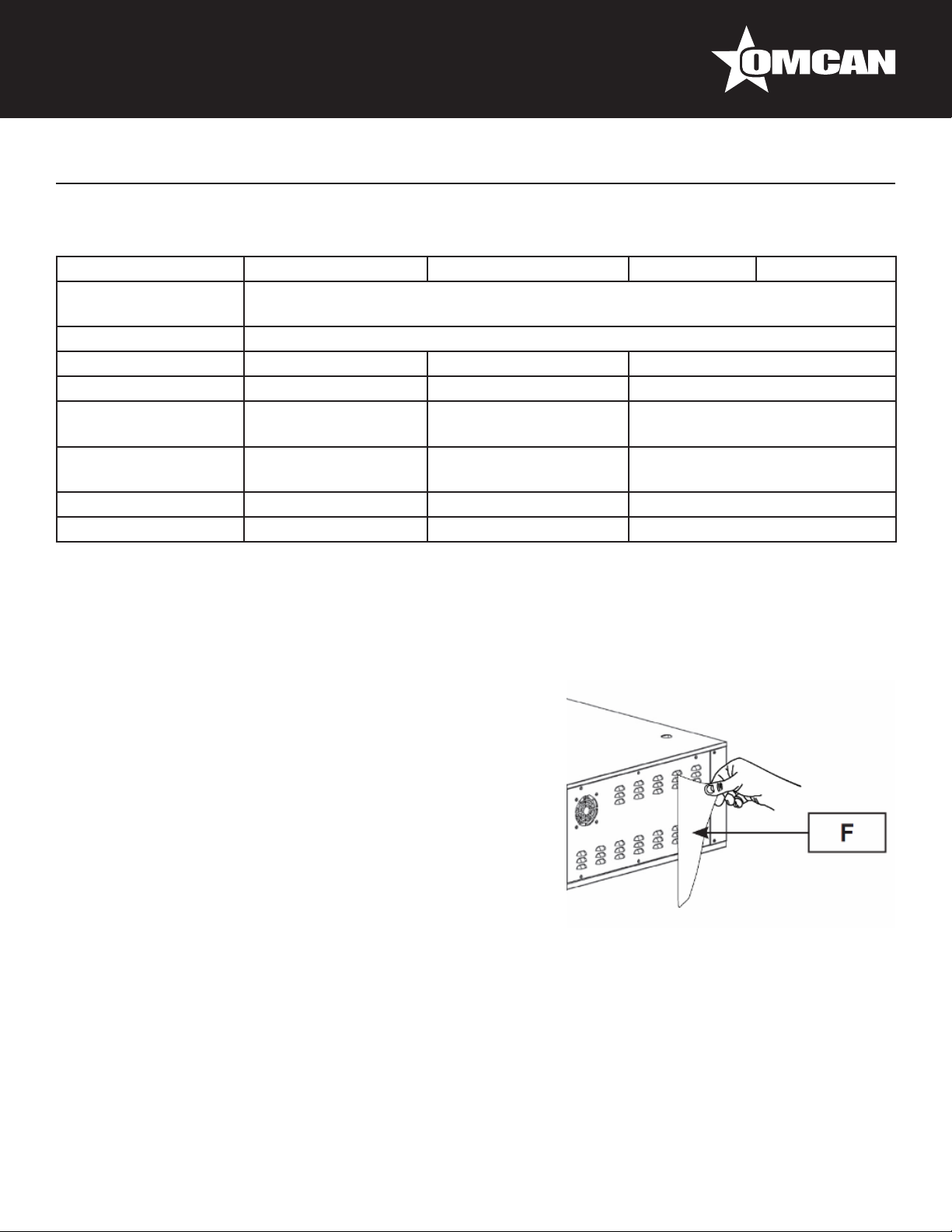
OVEN POSITIONING
Ensure that the oven is put on a stand with the suitable carrying
capacity and that is at.
After unpacking the oven from its packing, position it in prepared
location, taking into account the minimum distances.
Remove possible protections in polystyrene and take off the
protecting lm (F) avoiding to use tools which can damage the
surfaces.
EQUIPMENT HOOK-UP
Electrical connection
The oven is not provided with power supply cable. When connecting the appliance electrically, an automatic
RCD must be interposed with an opening distance between contacts of at least 3 mm. To connect the
appliance electrically it is essential to proceed in the following way:
• Remove the right side panel.
• Connect to the terminal block the power cable.
The power supply cable must be of H07-RNF type, with approved minimum cross section as prescribed by the
specic directive.
The electrical outlet must be easy to access, no moving should be necessary.
The electrical connection (plug) must be easily accessible, also following oven installation.
The distance between the machine and the socket must be adequate to not cause tension in the power supply
cable. In addition, the cable must not be located beneath the machine support base.
If the electrical power supply cable is damaged, it must be replaced by the technical assistance service
or by a qualied technician to prevent any risks.
GROUND CONNECTION
It is mandatory that the electrical system is equipped with a ground connection.
The appliance must be part of an equipotential system. The connection is done on terminal
marked with symbol which you will nd near the cable clamp. The section of the equipotential
wire must be at least 10mm2. The equipotential symbol is showed in the following gure.
6

DIGITAL OVEN START UP AND USE
COMMAND PANEL DESCRIPTION
Operation
Digital control panel
Main switch
The digital control panel allows the separate setting of top heating’s elements and bottom heating’s elements,
furnishing in real time the information on the temperatures. It also allows the activation and set point of the
timer, and the delay of lighting.
Cooking chamber light switch
FUNCTION OF THE KEYS
ON/OFF KEY
When the digital control panel is in position Off (switched off) one push enables the switch on of the same.
When the digital control panel is “on”, the continuous push for three seconds enables shifting into “Off”
(switched off).
TOP KEY / P1 PROGRAM
When the digital control panel is active (and the display shows the average baking chamber temperature),
pushing once the touch programme 1 is taken back and signal “P1” is shown. A minimum three seconds lasting
push enables the modication of top temperature set (of the selected programme).
BOTTOM KEY / P2 PROGRAM
When the digital control panel is active (and the display shows the average baking chamber temperature), by
7

Operation
pushing once the touch Programme 2 is taken back and “P2” is shown. A minimum three seconds lasting push
enables the modication of the bottom temperature (of the selected programme).
INCREMENT VALUE KEY / VISUALIZATION TOP TEMPERATURE
When the display shows the average baking chamber temperature, pushing once the touch top temperature is
shown. When programme modalities (p1 or p2) or other modalities active, same touch enables the increase of
the selected value.
DECREMENT VALUE KEY / VISUALIZATION BOTTOM TEMPERATURE
When the display shows the average baking chamber temperature, pushing once the touch bottom
temperature is shown. When programme modalities (p1 or p2) or other modalities, same touch enables
decrease of the selected value.
CLOCK KEY / DELAY TIME
When the digital control panel is active, three seconds continuous push enables to modify the switch on delay
(clock signal blinks)
COOKING TIMER KEY
When the digital control panel is active, a three seconds continuous push enables to modify the baking time
(timer signal blinks).
START/STOP KEY
When the digital control panel is active:
• After setting the delayed switch-on, the single push of start/stop touch enables the countdown of the
delayed switch on.
• When the delayed switch on countdown is under process, a three seconds lasting push of the start/stop
touch enables to disconnect the same.
• After setting the baking timer the single push of start/stop touch enables the baking timer countdown.
• When the baking timer countdown is under process a single push of start/stop enables to stop counting. A
further single push enables to activate again the counting.
• When the baking timer countdown is working, the three seconds lasting start/stop push enables to
deactivate the timer.
MEANING OF DISPLAY ICONS
°C
CELSIUS ICON: It is active when the temperature is set in Celsius.
FAHRENHEIT ICON: It is active when the temperature is set in Fahrenheit.
°F
8

Operation
TOP TEMPERATURE ICON: It is active when the top probe temperature is showed on the display. This
icon ashes during the variation of the top temperature set point.
BOTTOM TEMPERATURE ICON: It is active when the bottom probe temperature is showed on the
display. This icon ashes during the variation of the bottom temperature set-point.
TIMER ICON: It is active during the timer countdown. This icon ashes during the timer set-point.
CLOCK ICON: It is active during the delay time countdown. This icon ashes during the delay time set-
point.
TOP HEATING ELEMENTS ICON: It is active when the top heating elements are turned on.
BOTTOM HEATING ELEMENTS ICON: It is active when the bottom heating elements are turned on.
FIRST LIGHTING OF THE OVEN
At the rst use of the appliance it is advisable to heat the empty oven to eliminate bad smells caused by the
refractory stones evaporation and the inner metallic parts.
Procedure:
• Fully open the exhauster valve.
• Set the main switch in the position “1” after checking that the oven is connected with the power supply.
• Heat up the heating elements by pushing the on/off switch on the digital control panel.
• Leave the oven working (empty) for at least 8 hours at the temperature of 300° C before proceeding to the
rst baking.
START UP PHASE
After connecting the oven to the electric net rotate the main switch in position “1”. The digital control panel light
on and the word off is shown on the display. At this stage it is possible to start heating the oven by pushing the
on/off touch, with the consequent the heating elements start-up (top and bottom) of the baking chamber. By
pushing the on/off touch a short lamp-test takes place, after that for roughly 5 seconds the programme under
process is shown (p1 or p2). At this stage the display shows the average baking chamber temperature and
the thermostat setting takes place. This operation consists of the electronic and automatic use of the heating
elements to reach and maintain the temperatures set in the used programme (p1 or p2).
FUNCTION OF DIGITAL CONTROL PANEL
The main functions of the digital control panel are:
• Visualization of the baking chamber temperatures (average top and bottom).
• Top and bottom temperatures setting of baking programmes p1 or p2 (see ex. nr.1).
• Baking timer setting and activation (see ex. nr 2).
• Delayed switch-on setting and activation (see ex. nr 3).
9

Operation
GENERAL INDICATIONS FOR A GOOD COOKING
Generally for the food products it is not advisable to give precise temperature and baking time, because of their
different characteristics. Particularly, regarding pizza and similar products, time and temperatures depend on
the shape and thickness of the dough, as well as on the quantity and typology of the additional ingredients.
For those reasons it is always advisable to carry out previously some baking tests, (particularly when it is an
absolute new oven), with the aim of understanding as much as possible the characteristics and the functioning
of the oven.
Ideal time and temperature choice is determinant for a right pizza baking; mostly they depend on the
operator’s experience.
WORKING PHASE
While working, at any time the oven can be modied in its temperature parameters and programs; in addition,
pizza baking operation can be veried by inner chamber light. Once the oven has reached the set temperature
(visible on the display), it is possible to put in the pizza/s for baking, proceeding as follows:
• Open the door of the oven by the suitable handles.
• To light the inner chamber, set the lighting button (B) in the position “1”.
• Put in the oven the pizza/s to bake with suitable instruments for said use.
• Close the door again by the suitable handles and check the baking through the door glass. If wished, it is
possible to set the baking timer, which will warn with an acoustic signal the set baking time expiry.
• At baking over, open the door by the suitable handles and take out the pizza/s by suitable instruments for
said use.
When opening the door while the oven is on, it is important to stay at the right distance, to avoid being
invested by the heat coming out from the chamber.
Use suitable instruments to bake in and displace the pizzas in the baking chamber, to avoid burns.
When opening the door to bake the pizza/s, do not leave it opened for long time, to avoid heat
dispersion and consequently chamber temperature drop.
Avoid oil and fats to drop on bottom; if brought at high temperature can burn.
QUICK PROGRAM ACCESS
Press the TOP key to access the temperature setpoints related to program 1 (parameters P3 and P4), press
instead the BOTTOM key to access the temperature setpoints related to program 2 (parameters P5 and P6).
When pressing the TOP or BOTTOM key, the display shows the selected program for 5 seconds (Pr 1 in green
or Pr 2 in red). The setpoints are updated when the label disappears. If while Pr 1 or Pr 2 is displayed the TOP
or BOTTOM key is pressed, this display will disappear and the setpoints are updated. With the card ON, press
the TOP and BOTTOM keys for 3 seconds to display the program in use for 5 seconds. The selected program
is maintained also if the card is set to OFF or if the power is interrupted.
10

Operation
SETTING THE DATE AND TIME
The date and time must be set when the expansion with RTC is used for delayed start (parameter P20 = 2).
With the card OFF, press the CLOCK key for 3 seconds, and the display will show the label dd followed by the
day of the week from 1 to 7 (1= Monday, 7 = Sunday). Use the UP and DOWN keys to set the day of the week
and conrm by pressing the CLOCK key. Set the hours (label hh) and minutes (label mm) in the same way.
After conrming the minutes with the CLOCK key, the card will return to OFF.
NOTE: if P20=2, but the correct expansion is not installed (with RTC) an error is displayed (RTC label
ashing) at the end of the date and time setting procedure.
SETTING DELAYED START
The delayed start can be set only when the card is on and the timer is not being used for counting. Delayed
start can be set for the same day and for the following 6 days (for example, on Wednesday it is possible to
set the programmed start until maximum next Tuesday). From the day on which the rst delayed start is set,
the card will turn on EVERY DAY at the set time until the delayed start is turned off. Press the CLOCK key for
3 seconds, the display will show the ashing dd label followed by the day of the week from 0 to 7 (0=delayed
start off, 1=Monday, 7=Sunday). Use the UP and DOWN keys to set the day of the week and conrm by
pressing the CLOCK key. Set the hours (ashing hh label) and minutes (ashing mm label) in the same way.
After conrming the minutes with the CLOCK key, the card will turn OFF and with the clock icon on and the
central dotpoints ashing. To display the programmed start date, press the CLOCK key and the day of the
week, time and minutes of the programmed start time will be displayed. The card can be used by pressing the
ON/OFF key and setting it to the on status. If the card is turned off, the indication of the delayed start will be
redisplayed (ashing dotpoints and clock icon on). To disable the programmed start, turn on the card, access
the delayed start setting and disable it by setting dd to zero.
NOTE: If the card turns on in error because the user forgot to turn off the daily delayed start, the oven
will turn off automatically after P23 hours after starting if no key is pressed. Set P23=0 to disable this
function.
USE OF EXAUSTER VALVE
By the exhauster valve the operator can regulate the baking steams and fumes ow out from the baking
chamber, while in the same the heat is kept. It is advisable to keep the valve fully closed when the oven is
under heating; so, the set temperature is reached in shortest possible time. While baking regulate the valve
according to the exigencies.
SHUT DOWN PHASE
To shut down the oven, press the power button on the digital control panel and then turn the main switch to the
position “0”.
11
Operation
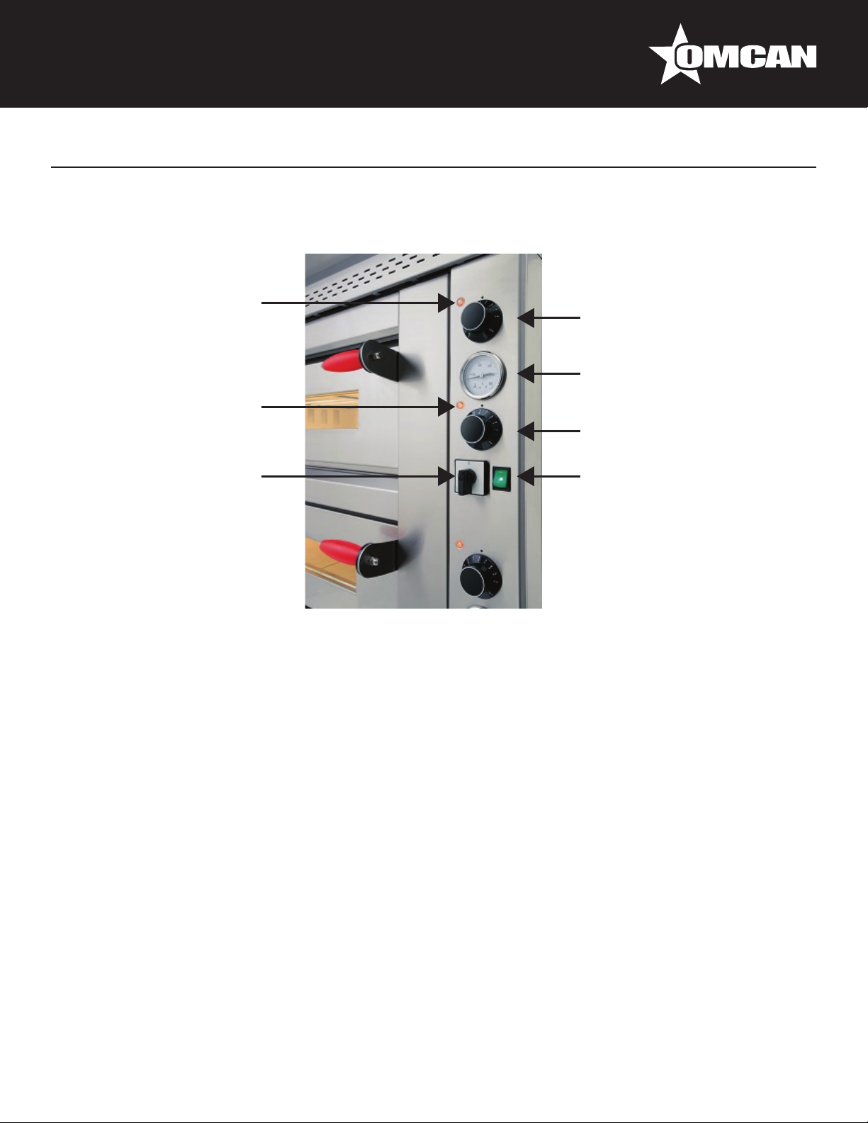
MECHANICAL OVEN START UP AND USE
COMMAND PANEL DESCRIPTION
Top heating elements
function pilot light
Bottom heating elements
function pilot light
Main switch
Thermostat for the regulation
of top temperatures
Digital control thermometer
Thermostat for the regulation
of bottom temperatures
Cooking chamber light switch
FIRST LIGHTING OF THE OVEN
At the rst use of the appliance it is advisable to heat the empty oven to eliminate bad smells caused by the
refractory stones evaporation and the inner metallic parts.
Procedure:
• Fully open the exhauster valve.
• Set the main switch in the position “1” after checking that the oven is connected with the power supply.
• Leave the oven working (empty) for at least 8 hours at the temperature of 300° before proceeding to the
rst baking.
START UP PHASE
After connecting the oven to the electric net rotate the main switch in position “1”. The digital thermometer
display shows the actual average temperature of the baking chamber. Rotate the thermostat knobs and until
the expected temperature. In this way top and bottom heating elements are under working and the relevant
light signals switch on.
GENERAL INDICATIONS FOR A GOOD COOKING
Generally for the food products it is not advisable to give precise temperature and baking time, because of their
different characteristics. Particularly, regarding pizza and similar products, time and temperatures depend on
12

Operation
the shape and thickness of the dough, as well as on the quantity and typology of the additional ingredients.
For those reasons it is always advisable to carry out previously some baking tests, (particularly when it is an
absolute new oven), with the aim of understanding as much as possible the characteristics and the functioning
of the oven.
Ideal Time and temperature choice is determinant for a right pizza baking; mostly they depend on the
operator’s experience.
WORKING PHASE
While working, at any time the oven can be modied in its temperature parameters; in addition, pizza baking
operation can be veried by inner chamber light. Once the oven has reached the set temperature (visible on
the display), it is possible to put in the pizza/s for baking, proceeding as follows:
• Open the door of the oven by the suitable handles.
• To light the inner chamber, set the lighting button (B) in the position “1”.
• Put in the oven the pizza/s to bake with suitable instruments for said use.
• Close the door again by the suitable handles and check the baking through the door glass.
• At baking over, open the door by the suitable handles and take out the pizza/s by suitable instruments for
said use.
When opening the door while the oven is on, it is important to stay at the right distance, to avoid being
invested by the heat coming out from the chamber.
Use suitable instruments to bake in and displace the pizzas in the baking chamber, to avoid burns.
When opening the door to bake the pizza/s, do not leave it opened for long time, to avoid heat
dispersion and consequently chamber temperature drop.
Avoid oil and fats to drop on bottom; if brought at high temperature can burn.
USE OF EXHAUSTER VALVE
While baking regulate the valve according to the exigencies. Oven is under heating; so, the set temperature
is reached in shortest possible time. By the exhauster valve the operator can regulate the baking steams and
fumes ow out from the baking chamber, while in the same the heat is kept.
SHUT DOWN PHASE
To shut down the oven turn the main switch to the position “0”.
13

Maintenance
Before performing any maintenance operations, including cleaning, take the following precautions:
• Ensure that the oven is not working end completely cold.
• Ensure that the electrical power is not present.
• Make certain that the electrical power cannot be accidentally reinserted. Disconnect the plug from the
electrical power socket.
• Use individual protection devices in compliance with the directive 89/391/CEE.
• Always operate using appropriate maintenance tools.
• Once maintenance and repairs are nished, before starting up the oven, reinstall all of the protection
devices and reactivate all of the safety devices.
ORDINARY MAINTENANCE FOR THE USER
As any equipment also our ovens requires simple, frequent and careful cleaning to ensure efcient, regular
functioning.
It is recommended to never use chemical products which are not specic for food preparation areas,
abrasives or corrosives for any reason. Avoid by all means using water jets, tools, rough or abrasive
instruments, such as steel wool, brillo sponges or any other item which could damage the surface of
the machine, and especially those that could compromise health safety.
CLEANING OF REFRACTORY PLAN
The oven must be cleaned at the end of each use, in compliance with the hygiene regulations and to safeguard
machine operation. Before proceeding the oven temperature must be at 350° C for roughly 60 minutes (setting
350° on the top and on the bottom as well), for an easy baking scoriae carbonization. Once reached the
temperature, switch off the oven and wait until the temperature drops until roughly 100°C (the best temperature
for cleaning). At this stage disconnect the electric power supply. After dressing in gloves and suitable dresses
as protection from burns, open the door and by a brush in natural ber with a long handle, proceed to a rst
removal of baking fragments from the refractory stones, then take them out by a suitable vacuum cleaner. At
the end, clean the refractory stone with an humid cloth.
EXTERNAL CLEANING OF THE OVEN
Oven external areas cleaning, external parts in stainless steel, door glass, and switch panel, must be carried
out at cold oven and at disconnected electric power supply. Use a sponge or a soft cloth, not abrasive, slightly
humidied with water or possibly with a neutral detergent not corrosive. In any case, do not use water jets
which can penetrate through the electric parts and heavily damage them, as well as bring a possible danger for
people.
14

Troubleshooting
WORKING ERRORS
SYMPTOM POSSIBLE CAUSE SUGGESTED REMEDY
The oven does not switch on. No electric Energy in the net. Check the general contactor, the
socket, the plug, and the supply
cable.
Main switch off (positioned on "0"). Rotate the main switch to position
"1".
The display is off in spite of the
main switch being on position 1
and the electric supply is in order.
Inner light bulb does not switch on. Burned inner light bulb. Replace inner light bulb.
The door is closed, but fume
comes out.
The baking chamber does not heat
suitably.
The baking chamber does not heat
suitably in spite of the temperature
being set rightly.
The temperature continues going
up over the set by thermo/timer.
Digital thermo/timer defective. Replace the digital thermo/timer.
Inner light bulb switch defected. Replace light bulb switch.
No electric supply power on the
light bulb.
Exhauster buttery valve closed. Open more the valve and check
The set temperature are too low. Set the right temperature.
One or more heating elements are
defected.
Power card contactors contacts
blocked (heating elements always
supplied).
Thermo/timer contacts defective. Check and if necessary replace the
Check electric connection with the
light bulb.
the right functioning.
Replace the defective heating
elements.
Check and, if necessary, replace
contactors card.
thermo/timer.
CONTROLLER ERRORS
DISPLAY ALARMS ALARMS MEANING POSSIBLE CAUSES EFFECT SOLUTIONS
ER1 Top probe damage
or probe connection
anomaly.
ER2 Bottom probe
damage or probe
connection anomaly.
Top probe defective
or anomaly probe
connection.
Bottom probe
damaged or probe
connection anomaly.
Top heating
elements
disconnection and
intermittent buzzer
sound.
Bottom heating
elements
disconnection and
buzzer intermittent
sound.
Connect again
and/or replace the
top probe.
Connect again
and/or replace the
bottom probe.
15

Troubleshooting
ERR Card probe damage. Card probe damage. All heating
elements
disconnection (top
and bottom) and
buzzer intermittent
sound.
HIT Probe temperature
too high.
Insufcient oven air
circulation due to
non respect of the
minimum distances
from surrounding
walls.
Power card contactor
contacts blocked
(heating elements
always power
supplied).
Switch panel cooling
fan damage (the
fan is tted in some
models only).
Disconnection
of all heating
elements (top
and bottom) and
intermittent buzzer
sound.
Disconnection
of all heating
elements (top
and bottom) and
intermittent buzzer
sound.
Disconnection
of all heating
elements (top
and bottom) and
intermittent buzzer
sound.
Replace the card
probe.
Wait until the
temperature of
the switch panel
area decreases
below the security
temperature and
check the causes
of the overheating.
French Instructions
SÉCURITÉ ET GARANTIE
AVERTISSEMENTS POUR L’INSTALLATEUR
Vériez que l’emplacement du four est en conformité avec les réglementations locales et nationales.
• Respecter les instructions de ce manuel.
• Ne pas exécuter les connexions électriques à l’aide de câbles temporaires ou non isolés.
• Vériez que la connexion à la terre du système électrique fonctionne correctement.
• Toujours utiliser les dispositifs de sécurité individuels et autres moyens de protection en conformité avec la
loi.
AVERTISSEMENT DE L’UTILISATEUR
Les conditions dans les environs où la machine sera installée doivent avoir les caractéristiques suivantes:
16

French Instructions
• La zone doit être sec.
• La zone doit disposer de sources d’eau et de chaleur à une distance sufsante.
• Ventilation et l’éclairage doivent être adaptés et conformes aux normes d’hygiène et de sécurité prévues
par les lois en vigueur.
• Le sol doit être plat et compact pour faciliter le nettoyage en profondeur.
• Il doit y avoir aucun obstacle d’aucune sorte dans le voisinage immédiat de la machine pouvant affecter la
ventilation normale de la machine.
En outre, l’utilisateur doit:
• Assurez-vous de garder les enfants loin de la machine quand elle est en marche.
• Respecter les instructions de ce manuel.
• Pas supprimer ou altérer les dispositifs de sécurité sur la machine.
• Faites toujours attention aux travaux à portée de main et ne pas utiliser la machine lorsque dans un état
distrait.
• Effectuer toutes les opérations avec un maximum de sécurité et de calme.
• Respecter les instructions et les avertissements afchés sur les étiquettes de la machine.
Les étiquettes sont des dispositifs de prévention des accidents, et doivent donc toujours être parfaitement
lisible. Si ceux-ci devraient être endommagés et illisibles, il est obligatoire de les remplacer en demandant le
remplacement du fabricant.
• A la n de chaque quart de travail, avant les opérations de nettoyage, d’entretien ou de transfert,
débrancher l’alimentation électrique.
AVERTISSEMENTS POUR L’OPÉRATEUR DE MAINTENANCE
Respectez les instructions indiquées dans ce manuel.
• Toujours utiliser les dispositifs de sécurité individuels et d’autres moyens de protection.
• Avant de commencer toute opération de maintenance, assurez-vous que le four, il a été utilisé, est refroidi.
• Si l’un des dispositifs de sécurité est usée ou défectueuse, le four est également considéré comme
défectueux et ne pas être utilisé.
• Coupez l’alimentation électrique avant d’intervenir sur les pièces et les connecteurs électriques ou
électroniques.
GARANTIE 1 AN
AVERTISSEMENT:
Les matériaux d’emballage sont considérés comme des déchets solides urbains normale et peuvent donc être
éliminés sans difculté.
En tout cas, pour le recyclage approprié, nous suggérons au rebut des produits séparément (type de
déchets) selon les normes en vigueur.
NE PAS JETER LES EMBALLAGES DANS L’ENVIRONNEMENT!
17
French Instructions19French Instructions
SPÉCIFICATIONS TECHNIQUES
Modèle PE-IT-0024-S PE-IT-0048-D PE-IT-0049-D PE-IT-0049-DD
Température
Maximale
Électrique 220V/60/3
Puissance 6.6 kW 13.2 kW 18 kW
Volume 23.7 Cu. Ft. 36.7 Cu. Ft. 48.7 Cu. Ft.
Dimensions de la
Chambre
Dimensions
Extérieures
Poids Net 115 kg. / 253 lbs. 183 kg. / 403.4 lbs. 231 kg. / 509 lbs.
Poids Brut 132 kg. / 291 lbs. 201 kg. / 443 lbs. 254 kg. / 560 lbs.
27.6” x 27.6” x 5.9”
701 x 701 x 150mm
43” x 39.8” x 16.9”
1092 x 1011 x 429mm
(27.6” x 27.6” x 5.9”) x 2
(701 x 701 x 150mm) x 2
43” x 39.8” x 29.5”
1092 x 1011 x 749mm
INSTALLATION
842°F / 450°C
(41.3” x 27.6” x 5.9”) x 2
(1049 x 701 x 150mm) x 2
56.9” x 39.8” x 29.5”
1445 x 1011 x 749mm
L’installation doit être exécutée par du personnel qualié dans le respect des réglementations locales et
nationales.
POSITIONNEMENT DU FOUR
Assurez-vous que le four est placé sur un support avec la
capacité de charge et qui est adapté à plat.
Après avoir déballé le four de son emballage, placez-le dans
l’emplacement préparé, en tenant compte des distances
minimales.
Retirez les protections possibles dans le polystyrène et enlever
le lm de protection (F) en évitant d’utiliser des outils qui peuvent
endommager les surfaces.
ÉQUIPEMENT HOOK-UP
Raccordement électrique
Le four est pas fourni avec un câble d’alimentation. Lors du raccordement électrique, un disjoncteur différentiel
automatique doit être interposé avec une distance d’ouverture entre les contacts d’au moins 3 mm. Pour
connecter l’appareil électrique, il est indispensable de procéder de la manière suivante:
• Retirez le panneau latéral droit.
• Connectez à la borne bloquer le câble d’alimentation.
Le câble d’alimentation doit être de type H07-RNF, avec une section minimale approuvé tel que prescrit par la
directive spécique.
La prise électrique doit être facile d’accès, pas de mouvement devrait être nécessaire.
18
 Loading...