

Page 1
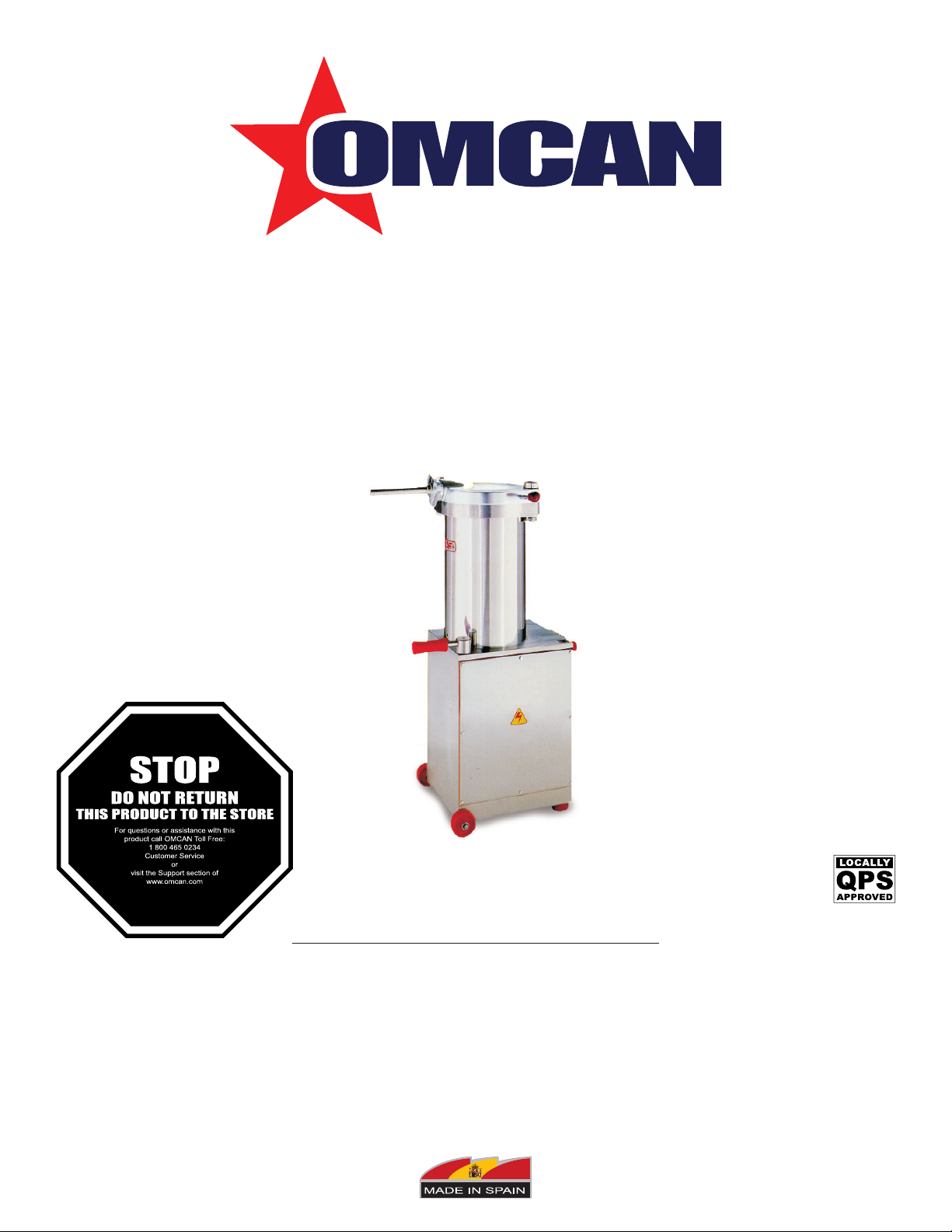
Sausage Stuffers
Models SS-ES-0015, 0020, 0026, 0031, 0042, 0052
Items *13743, *13744, 41708, *13745, 13746, *13750, 13752, *13751,
*13753, *41709, *13755, 13756, 13757, 13758, 13759, 17146
Instruction Manual
Revised - 12/07/2017
Toll Free: 1-800-465-0234
Fax: 905-607-0234
Email: service@omcan.com
www.omcan.com
*
Page 2

Table of Contents
Model SS-ES-0015-PA / Model SS-ES-0015-PAM / Model SS-ES-0020-PA
Model SS-ES-0020-PAM / Model SS-ES-0026-PA / Model SS-ES-0026-PAM
Model SS-ES-0026-PAS / Model SS-ES-0026-PASM / Model SS-ES-0031-PAS
Model SS-ES-0031-PASM / Model SS-ES-0042-PAS / Model SS-ES-0042-PASM
Model SS-ES-0052-PAS / Model SS-ES-0052-PASM
Section
General Information
Safety and Warranty
Technical Specications
Installation
Operation
Maintenance
Troubleshooting
----------------------------------------------------------------------------------------------------- 7 - 9
----------------------------------------------------------------------------------------------------- 9 - 10
----------------------------------------------------------------------------------------------- 11 - 15
----------------------------------------------------------------------------------------- 3 - 4
---------------------------------------------------------------------------------------- 4 - 6
------------------------------------------------------------------------------------------- 15 - 16
Page
---------------------------------------------------------------------------------------- 7
Parts Breakdown
Electrical Schematics
Notes
Warranty Registration
-------------------------------------------------------------------------------------------------------------- 26
----------------------------------------------------------------------------------------- 17 - 23
------------------------------------------------------------------------------------ 24 - 25
----------------------------------------------------------------------------------------- 27
2
Page 3

General Information
Omcan Manufacturing and Distributing Company Inc., Food Machinery of America, Inc. dba Omcan
and Omcan Inc. are not responsible for any harm or injury caused due to any person’s improper or
negligent use of this equipment. The product shall only be operated by someone over the age of 18, of
sound mind, and not under the inuence of any drugs or alcohol, who has been trained in the correct
operation of this machine, and is wearing authorized, proper safety clothing. Any modication to the
machine voids any warranty, and may cause harm to individuals using the machine or in the vicinity of
the machine while in operation.
CHECK PACKAGE UPON ARRIVAL
Upon receipt of an Omcan shipment please inspect for external damage. If no damage is evident on the
external packaging, open carton to ensure all ordered items are within the box, and there is no concealed
damage to the machine. If the package has suffered rough handling, bumps or damage (visible or concealed),
please note it on the bill of lading before accepting the delivery and contact Omcan within 24 hours, so we may
initiate a claim with the carrier. A detailed report on the extent of the damage caused to the machine must be
lled out within three days, from the delivery date shown in the shipping documents. Omcan has no recourse
for damaged products that were shipped collect or third party.
Before operating any equipment, always read and familiarize yourself with all operation and safety
instructions.
Omcan would like to thank you for purchasing this machine. It’s of the utmost importance to save
these instructions for future reference. Also save the original box and packaging for shipping the
equipment if servicing or returning of the machine is required.
---------------------------------------------------------------------------------------------------------------------------------------------------
Omcan Fabrication et distribution Companie Limité et Food Machinery d’Amerique, dba Omcan et
Omcan Inc. ne sont pas responsables de tout dommage ou blessure causé du fait que toute personne
ait utilisé cet équipement de façon irrégulière. Le produit ne doit être exploité que par quelqu’un de
plus de 18 ans, saine d’esprit, et pas sous l’inuence d’une drogue ou d’acohol, qui a été formé pour
utiliser cette machine correctement, et est vêtu de vêtements de sécurité approprié. Toute modication
de la machine annule toute garantie, et peut causer un préjudice à des personnes utilisant la machine
ou des personnes à proximité de la machine pendant son fonctionnement.
VÉRIFIEZ LE COLIS DÈS RÉCEPTION
Dès réception d’une expédition d’Omcan veuillez inspecter pour dommages externes. Si aucun dommage
n’est visible sur l’emballage externe, ouvrez le carton an de s’assurer que tous les éléments commandés
sont dans la boîte, et il n’y a aucun dommage dissimulé à la machine. Si le colis n’a subi aucune mauvaises
manipulations, de bosses ou de dommages (visible ou cachée), notez-le sur le bond de livraison avant
d’accepter la livraison et contactez Omcan dans les 24 heures qui suivent, pour que nous puissions engager
une réclamation auprès du transporteur. Un rapport détaillé sur l’étendue des dommages causés à la machine
doit être rempli dans un délai de trois jours, à compter de la date de livraison indiquée dans les documents
d’expédition. Omcan n’a aucun droit de recours pour les produits endommagés qui ont été expédiées ou cueilli
par un tiers transporteur.
3
Page 4

General Information
Avant d’utiliser n’importe quel équipement, toujours lire et vous familiariser avec toutes les opérations
et les consignes de sécurité.
Omcan voudrais vous remercier d’avoir choisi cette machine. Il est primordial de conserver ces
instructions pour une référence ultérieure. Également conservez la boîte originale et l’emballage pour
l’expédition de l’équipement si l’entretien ou le retour de la machine est nécessaire.
---------------------------------------------------------------------------------------------------------------------------------------------------
Omcan Empresa De Fabricacion Y Distribucion Inc. Y Maquinaria De Alimentos De America, Inc. dba
Omcan y Omcan Inc. no son responsables de ningun daño o perjuicío causado por cualquier persona
inadecuada o el uso descuidado de este equipo. El producto solo podra ser operado por una persona
mayor de 18 años, en su sano juicio y no bajo alguna inuencia de droga o alcohol, y que este ha sido
entrenado en el correcto funcionamiento de esta máquina, y ésta usando ropa apropiada y autorizada.
Cualquier modicación a la máquina anúla la garantía y puede causar daños a las personas usando la
máquina mientras esta en el funcionamiento.
REVISE EL PAQUETE A SU LLEGADA
Tras la recepcion de un envio Omcan favor inspeccionar daños externos. Si no hay daños evidentes en el
empaque exterior, Habra el carton para asegurararse que todos los articulos solicitados ésten dentro de la
caja y no encuentre daños ocultos en la máquina. Si el paquete ha sufrido un manejo de poco cuidado, golpes
o daños (visible o oculto) por favor anote en la factura antes de aceptar la entrega y contacte Omcan dentro
de las 24 horas, de modo que podamos iniciar una reclamación con la compañia. Un informe detallado sobre
los daños causados a la máquina debe ser llenado en el plazo de tres días, desde la fecha de entrega que se
muestra en los documentos de envío. Omcan no tiene ningun recurso por productos dañados que se enviaron
a recoger por terceros.
Antes de utilizar cualquier equipo, siempre lea y familiarizarse con todas las instrucciones de
funcionamiento y seguridad.
Omcan le gustaría darle las gracias por la compra de esta máquina. Es de la mayor importancia para
salvar estas instrucciones para futuras consultas. Además, guarda la caja original y el embalaje para el
envío del equipo si servicio técnico o devolución de la máquina que se requiere.
Safety and Warranty
This machine has moving mechanical parts and uses voltages that are potentially hazardous. Severe, even
life-threatening, personal injury could result if the instructions contained in this manual are not followed.
Before operating the unit, please read this manual thoroughly. This manual should be kept for future reference
and given to every user of the machine. The following clauses limit the liability of the manufacturer and its
representatives:
• This machine should only be installed by a qualied electrician. Once installed, do not tamper with the
4
Page 5

Safety and Warranty
electrical wiring or components of the machine.
• Do not use the machine without having received previous instructions about its use, maintenance and
safety devices from an experienced operator.
• Read the instruction manual carefully before using the machine.
• Do not use the machine without the personal safety equipment required by law.
• Do not tamper with the xed guards, the safety interlock electrical switches or any other safety devices.
• Always keep hands at a safe distance from the moving parts of the machine.
• Do not leave machine unattended while switched on or in operation.
• Always disconnect the power supply before removing shrouds, removable guards, covers, doors, fences,
panels, etc. for servicing, cleaning, or repairs.
• Do not open the machine or tamper with its internal parts. There are no internal components that require
adjustment or maintenance on the part of the user.
• Should the machine malfunction, turn it off immediately and notify the supervisor.
• Installation must be in accordance with the operating instructions and with local and state hygiene
standards and safety codes. Compliance with codes is the responsibility of the Owner and Installer.
• Before operating the machine, make sure that it is properly grounded and/or connected to a circuit leakage
breaker and thermal switch. Failure to do so could result in electric shock.
• Make sure the safety signs and stickers are rmly afxed to the machine, that they are legible, and that
they have not been blurred or erased after the machine is cleaned. If they become damaged or lost, ask
your dealer for new ones and replace them.
• Keep your work area well lit and free of obstacles.
• When operating the machine never wear loose clothing or jewelry that could get caught in the moving
parts.
• Disconnect power.
• Keep children and on-lookers at a safe distance.
• Do not pull on the cord to remove the electrical plug from the socket.
• To avoid damaging the electrical cord, keep it out of areas where it can be stepped on.
• Do not alter or modify the machine’s original design in any way.
• Should the machine need repairs, consult the ofcial dealer where the machine was purchased.
• Use only genuine TALSA parts and accessories and have them properly installed by a qualied technician.
• This machine has been designed exclusively for meat processing. Any other use of this machine is not
in accordance with its intended application. The manufacturer assumes no responsibility for any possible
damage or injury resulting from improper use of this machine.
Additional operating instruction manuals are available from your dealer. Your local dealer will be happy to
answer any further questions you may have.
LIST OF POSSIBLE OPERATING HAZARDS
Read and review thoroughly the following operating hazards.
MECHANICAL HAZARDS
• Crushing hands, ngers etc. on the barrel when closing the lid.
• Crushing hands, ngers etc. between the lid and the piston while the latter is being raised, especially when
the lid is not completely open.
5
Page 6

Safety and Warranty
• Crushing hands, ngers etc. between the piston and the upper part of the base during the dismantling of
the removable barrel on E models.
• Personal injury should the machine tip over if it is raised too high while being moved (since the llers are on
wheels, this is an important hazard).
• Foot injuries should the piston fall during dismantling or cleaning.
ELECTRICAL HAZARDS
• Electric shock due to direct or indirect contact with electrical current.
• Electric shock due to defective electrical parts.
NOISE HAZARDS
• Hearing damage should any modication of the machine’s original design raise noise emission levels
above 85 dB(A).
PERSONAL HEALTH HAZARDS
• Changes in the nature of the food mixture if hygiene and cleaning instructions have not been followed.
1 YEAR PARTS AND LABOR WARRANTY
Within the warranty period, contact Omcan Inc. at 1-800-465-0234 to schedule an Omcan authorized
service technician to repair the equipment locally.
Unauthorized maintenance will void the warranty. Warranty covers electrical and part failures, not
improper use.
Please see www.omcan.com/warranty.html for complete info.
WARNING:
The packaging components are classied as normal solid urban waste and can therefore be disposed of
without difculty.
In any case, for suitable recycling, we suggest disposing of the products separately (differentiated
waste) according to the current norms.
DO NOT DISCARD ANY PACKAGING MATERIALS IN THE ENVIRONMENT!
6
Page 7

Technical Specications
Model HP Capacity Electrical Weight Item Number
SS-ES-0015-PA 0.75 HP 33 lbs. 208V/60/3 223 lbs. 13743
SS-ES-0015-PAM 1.75 HP 33 lbs.
SS-ES-0020-PA 0.75 HP 44 lbs. 208V/60/3 231.5 lbs. 13745
SS-ES-0020-PAM 1.75HP 44 lbs. 220V/60/1 231.5 lbs. 13746
SS-ES-0026-PA 1.5 HP 57 lbs. 208V/60/3 289 lbs. 13750
SS-ES-0026-PAS 1.5 HP 57 lbs. 208V/60/3 289 lbs. 13752
SS-ES-0026-PAM 2.25 HP 57 lbs. 220V/60/1 289 lbs. 13751
SS-ES-0026-PASM 2.25 HP 57 lbs.
SS-ES-0031-PAS 2 HP 68 lbs. 220V/60/3 315.25 lbs. 13755
SS-ES-0031-PASM 2.25 HP 68 lbs. 220V/60/1 315.25 lbs. 13756
SS-ES-0042-PAS 2.5 HP 92 lbs. 220V/60/3 527 lbs. 13757
SS-ES-0042-PASM 2.5 HP 92 lbs. 220V/60/1 527 lbs. 13758
SS-ES-0052-PAS 2.5 HP 114 lbs. 220V/60/3 610.7 lbs. 13759
SS-IT-0052-PASM 2.5 HP 114 lbs. 220V/60/1 610.7 lbs. 17146
220V/60/1
223 lbs.
110V/60/1 41708
220V/60/1
289 lbs.
110V/60/1 41709
13744
13753
Installation
(Machine should only be installed by a qualied technician and in compliance with local codes).
The electrical installation of the workplace should be equipped with power surge full protection, which should
then be adjusted to the technical specications of your particular unit (see below).
UNPACKING AND POSITIONING
Always keep the machine in a vertical position. Take the machine out of its box. Remove the knee lever (and
the upper lid screws for E models) from the inside of the barrel and set them in their proper positions. Do not
use the knee lever to move the machine. The machine comes with two xed (non-castor) wheels in the front
and two plastic anti-vibration legs in the back; lift the back part of the machine using the transport handle and
move the machine to the desired location (two people are necessary for moving the heavier H42 and H52
models). Do not raise the ller/stuffer too high when moving it since it could tip over, causing personal injury.
Place the machine on a level surface. Should the machine wobble, adjust the anti-vibration legs until it is
perfectly stable and level. The machine should be placed so that the plug is easily accessible.
IMPORTANT: Remove the protective transport cap on the oil inlet (marked OIL) and replace it with the
depressurized oil cap/dipstick enclosed with the machine. Also make sure that the air holes located at the base
7
Page 8

Installation
of the barrel are totally clear; if not, the piston will not function properly.
CONNECTING THE MACHINE
Make sure the electrical characteristics of the machine (connection, voltage, and frequency) are suited to your
power source. (These specications are given in detail on the technical specications sticker afxed to the
machine itself; there is a tolerance of ±10% for voltage and of ±2% for frequency). If the specications are
compatible with your power source, refer to the OPERATING INSTRUCTIONS section below. If the electrical
features of the machine are not compatible with your power source and your machine is a dual voltage, three-
phase unit, adjust the voltage as described below in the CHANGING VOLTAGE section. Once the machine has
been installed and the oil level inside the reservoir has been checked using the dipstick attached to the oil inlet
screw, check the turning direction of the three-phase motor. If the phases are correctly adjusted, the piston will
rise and fall when the knee pedal is pushed. If the phases are incorrect, the pump will not work properly; the
motor will make noise, but the piston will not move. Stop immediately and interchange two of the three phases
in the plug. Make sure that the plug and outlet are appropriate for the machine.
IMPORTANT: the wiring in the electrical cord is normally assigned as follows: Phase(s): • Black, Brown,
Gray • Ground wire: Two-colored Yellow/Green or Green. Check the wiring before connecting; call a qualied
electrician if the electrical specications do not correspond with your power source.
HYDRAULIC OIL FILLING
The H ller/stuffer is delivered with hydraulic oil already in the internal reservoir; therefore, the initial addition of
oil to the hydraulic system is usually unnecessary. In the exceptional case that a machine is delivered without
hydraulic oil in the reservoir, do not turn it on. Fill the reservoir as follows:
• Remove the oil reservoir screw (marked OIL) located in the upper part of the base.
• Check that the correct level of oil is inside the reservoir by using the dipstick (with max./min. marks)
attached to the oil reservoir cap.
• Using a funnel, pour the hydraulic oil into the tank. Do not ll the reservoir to the top since a certain
amount of air must remain in the reservoir to allow for expansion. Use oils for medium pressure hydraulic
assemblages (approx. 100 bar), and of a viscosity of approximately 5º Engler (equivalent to IS03498: cat
HL VG46 or DIN8659: HL-46). After lling the reservoir, raise and lower the piston several times to purge
any remaining air from the hydraulic circuit.
Always ll the reservoir to the maximum level without exceeding it since the more oil there is in the reservoir,
the more effectively the heat given off by the hydraulic assemblage will be cooled. This helps lengthen the life
of the oil. Because there should be no loss of oil or oil vapors, an adequate level of hydraulic oil should last
several years (between 2500 and 5000 hours of use), making it unnecessary to check the oil level as long as
the machine is functioning well. For more information, see the MAINTENANCE section below.
CHANGING THE VOLTAGE
IMPORTANT: Only for three-phase machines with dual voltage motor 380/220 Volt (400/230 Volt for EU), etc.
This operation should only be carried out by a qualied electrician. Do not connect the machine to the power
source. If already plugged in, unplug it and leave it disconnected for the entire process. Remove the screws
from the steel lid on the base. Remove the lid.
8
Page 9

Installation
CHANGING THE VOLTAGE ON A MODELS (AUTOMATIC-CONTACTOR)
MOTOR: Open the connection terminal box of the motor by unscrewing the four screws. Loosen the six small
nuts on the connection terminals and place the plates in the correct position.
CONTACTOR: will need to be replaced by a qualied technician to a new one of same voltage than power
supply.
CHANGING THE VOLTAGE ON “I” MODELS (SWITCH)
MOTOR: Open the connection terminal box of the motor by unscrewing the four screws. Loosen the six small
nuts on the connection terminals and place the plates in the correct position.
Operation
IMPORTANT: Before operating the unit, read this manual thoroughly. Test the machine when it is empty before
using it on food.
HANDLING STEPS
• Loosen the screws on the upper lid (only for E models) and open the lid with a slight upward motion to
reduce friction.
• Wash the meat barrel, the underside of the lid, and the appropriate nozzle with hot water.
• Lower the pressure of the machine to the minimum by turning the red knob that regulates the lling speed
counter-clockwise.
• Plug the machine in.
• Turn the gray switch located on the right of the machine to the “I” (start) position (I models only).
• Turn the machine on by pushing the knee lever.
• Push the knee lever all the way back to lower the piston enough to make room for the desired amount of
mixture.
• Place the mixture in the meat barrel, pressing each new load of mixture down to avoid the formation of air
pockets which could break the casing during the lling process.
• Put the green lid gasket in place.
• Using the knee pedal, raise the piston until the mixture reaches the top of the barrel.
• Using food fat or another USDA approved shortening, grease the upper part of the lid gasket and the
underside of the lid.
• Carefully close the lid with a light lifting movement to avoid friction, taking care not to pinch or crimp the
cover gasket in the process.
To close the lid, use only the lever incorporated in the lid itself; do not use the nozzle. Take extreme care not to
trap or pinch your hands while closing the lid.
• After putting the screws back on the upper lid (E models only), place the optimum-size nozzle (largest
9
Page 10

Operation
diameter and shortest length possible) on the lid, locking it in place by turning the triangular nozzle nut.
Prepare the proper amount of casing.
• Push the knee lever all the way forward to the piston raising position. Always push the knee lever rmly; do
not use it as a speed control regulator.
• Carefully raise the pressure by slowly turning the pressure control knob clockwise. Do not raise the
pressure suddenly, as this could cause the mixture to come out of the nozzle too quickly.
• Note how the piston will begin to rise and air will come out of the nozzle.
• Once the mixture begins to come out of the nozzle, release the pressure and place the casing on the
nozzle. Adjust the red pressure control knob to select the optimum speed.
• Once the casing has been lled, push the knee lever back to the piston lowering position until the piston is
at its lowest level in the barrel.
• To stop the hydraulic assemblage, bring the knee pedal to the central position.
• Turn the gray switch located on the right of the machine to the “O” (stop) position (I models only).
• When nished using the machine, clean it, lower the piston to its lowest position in the barrel, unplug the
machine and make sure that the machine cannot roll.
USEFUL TIPS
• Do not use the machine without having received previous instructions from an experienced operator.
• This instruction manual should be read carefully and fully understood before using the machine.
• Test the machine when it is empty before using it on food.
Observe all the appropriate hygiene measures when handling food products; use adequate protective
equipment and procedures (washing, gloves, cap, apron, etc.). To produce sausage with a better appearance
and less smearing, as well as for more uniform mixture and less wear and tear on the machine, we recommend
the use of:
• Horn with the largest diameter and shortest length possible.
• Finely chopped mixtures at the least coldest temperature possible.
Consequently, we recommend avoiding very long nozzles or nozzles with small diameters when using roughly
chopped or very cold mixtures. If nozzles of special dimensions are needed, order them from your dealer.
Never use the nozzle to close the lid since the rim could break. Close the lid with the lid lever only. Do not
open or close the lid without the green gasket in place since this could lead to scratches on the lid and clamp.
The barrel lid cannot be opened without rst slightly lowering the piston by placing the knee pedal in the down
position. This will stop the mixture from blocking the opening. Place the machine as close to the work surface
as possible. The locations of the nozzle and knee lever allow the nozzle to be located completely over the work
surface, thus guaranteeing that no liquid falls onto the oor or the operator. In order to prevent overheating in i
models, turn the machine off after use. Turn the motor on only when in use.
Work at a reasonable pace, thus avoiding constant stopping and restarting of the hydraulic assemblage.
This machine is not designed to withstand permanent, uninterrupted use at high pressure, but rather to run
intermittently with pauses to allow for the dissipation of the heat generated, the amount of which depends on
the consistency of the mixture. Because of the pressure transmitted by the pump, after prolonged periods of
use the hydraulic oil may reach temperatures of up to 60ºC (140ºF) and the base side panel may become
warm to the touch.
10
Page 11

Maintenance
CLEANING
IMPORTANT: In order to avoid mechanical hazards during cleaning operations and piston dismantling, always
open the lid completely when raising the piston.
CLEANING INSTRUCTIONS
To clean the outside of the machine use hot water and a mild cleanser. Do not use any abrasive products,
especially those that could scratch warning stickers and labels. Never wet or dampen the electrical elements
of the machine (switches, cables, etc.). Never use a jet of water to clean any part of the machine, especially
the air holes on the side of the oil tank cap. At the end of each workday, the underside of the lid (the mixture
exit hole), as well as the nozzle(s) and the nozzle nut should be cleaned thoroughly. If necessary, clean the
inside of the nozzles with a round brush. Do not open or close the lid without the green gasket in place since
this could scratch the lid and clamp. Using hot water only, rinse the lid bolt and bearing to eliminate any residue
that could crystallize (salts, spices, etc.) and thus impede the proper functioning of the lid. The upper part of
the black piston gasket should also be cleaned daily, following these steps:
• Open the lid completely and remove the green lid gasket.
• Press the knee lever until the piston rises to its uppermost position. Part of the black piston gasket will now
be accessible via the upper part of the barrel. Clean it with a damp cloth.
We recommend that you periodically clean the piston and barrel interior thoroughly:
• Loosen the screws on the upper lid (E models only), open the lid completely and remove the green lid
gasket.
• Press the knee lever until the piston rises to its uppermost position.
• With the piston at its highest position, simultaneously push the knee lever and, with the aid of the two pivots
of the wrench supplied, unscrew the piston-locking bolt (two turns) located in the center of the piston.
• Screw the wrench completely into the piston hole. The piston will rise above the rim of the barrel.
• Pull the wrench up to remove the piston from the barrel.
• Unplug the machine.
• Clean the inside of the cylinder. Make sure that the bottom of the cylinder is completely DRY to avoid the
formation of water droplets, which could eventually lead to the formation of rust on the upper part of the
base.
IMPORTANT: Piston and barrel cleaning can also be done by dismantling the removable barrel (E models
only); however, to avoid mechanical hazards as well as damage to the piston gaskets, we advise removal of
the piston only.
CLEANING PRECAUTIONS
Because of the weight of the piston, use caution when moving it. Clean the piston and the black piston gaskets
(1 or 2, depending on the model). To avoid damaging the gaskets, never use sharp or pointed tools (knives,
screwdrivers) to remove them. To reduce the noise caused by the movement of the piston, grease the piston
gaskets with food fat or another USDA approved shortening before putting them back into the barrel. Never
introduce water inside the barrel since it could lter down to the base of the machine and affect the electrical
and mechanical components. The holes in the bottom of the barrel are vents for air only.
To reassemble the piston, make sure that the bottom of the barrel is completely dry, then place the piston in the
11
Page 12

Maintenance
barrel and screw the piston-locking bolt tight, making sure that the smaller gasket is properly placed. Raise and
lower the piston, and tighten the piston locking bolt again, making sure it does not bend against the pressure of
the lid. Grease the thread of the piston-locking bolt before replacing it; this will make future dismantling easier.
When the machine is not in use, leave the piston head at the bottom of cylinder, where it will be submerged in
hydraulic oil. This will lengthen the life of the ram and the gaskets.
GENERAL CLEANING ADVICE
Cleaning steps Products Method Tools Notes
Supercial cleaning Manual Spatula Remove all residue directly after use,
removing smaller machine parts if
necessary.
Extensive cleaning Mild detergent Manual Brush, bucket Leave product to work ± 15 minutes.
Rinsing Warm water Manual Sponge, bucket Warm water 40/50 º C - 100/120 º F.
Inspection Check critical points and problematic
parts.
Disinfecting Disinfectant
products
Rinsing Drinking water Manual Sponge, bucket
Drying Cleaning cloth
Maintenance Lubricating oil Manual Cleaning cloth External machine parts.
Manual Sponge, cleaning
cloth
After completing all other cleaning
operations.
SPECIFIC CLEANING ADVICE
Interval Cleaning area Method Products Tools Notes
Daily Underside of the lid, lid
gasket, inside of the
barrel and piston bolt
retaining screw
Bi-Weekly Piston, piston gaskets
and gasket of piston bolt
retaining screw
These cleaning instructions have been elaborated for companies with just one shift; shorter intervals should be
observed in companies with many work groups.
IMPORTANT: Among the parts which should be cleaned daily (see “SPECIFIC CLEAN ADVICE” above),
the piston bolt retaining screw must be cleaned thoroughly by dismantling it. In E models, the following parts
should also be dismantled for better cleaning: lid closing nuts, lid, barrel. Piston removal: See above.
Manual Mild detergent,
warm water
Manual Mild detergent,
warm water
Sponge,
cleaning cloth
Sponge,
cleaning cloth
Eliminate dirt from retaining
screw using a brush if
necessary. Avoid build up of
residues.
To remove the piston, follow
the instructions above.
MAINTENANCE
IMPORTANT: Unplug the machine before proceeding with maintenance and inspection.
12
Page 13

Maintenance
During maintenance and inspection operations always follow the safety instructions in this manual. Mechanical
breakdowns caused by inadequate or improper maintenance can lead to high repair costs as well as
work stoppages; therefore, regular and adequate maintenance is indispensable. The safety and life of the
machine depend on many factors, including proper maintenance. Because different companies have different
shift schedules, it is impossible to prescribe in advance how often you should proceed with inspections,
maintenance or replacement. Adjust your inspection routine to the number of work groups you have in
your company. Our local dealer will be delighted to give you further information. The table below contains
information about maintenance and inspection (control intervals, critical points, etc.) for a machine under
normal use.
MAINTENANCE AND INSPECTION SCHEDULES
After reading the following, consult the MAINTENANCE AND INSPECTION TIPS section for more details.
Control interval Critical points / Maintenance information
Daily Check green lid gasket and replace it if necessary.
Check the two black piston gaskets and replace them if necessary.
Check the air holes located at the base of the barrel and clear them of any
obstruction.
Monthly Check the lid closure and tighten if necessary by regulating the lid xing
bolts (P models only).
Yearly Check hydraulic oil level and rell the reservoir if necessary.
Every 2500-5000 service hours Change hydraulic oil.
Check oil lter and replace it if necessary.
MAINTENANCE AND INSPECTION TIPS
Green lid gasket: Replace if damaged or if leaks are observed. This gasket is reversible, i.e. it can be used
with either side facing up. A spare gasket comes with the machine. The gasket is made from a non-toxic
material that is safe for alimentary use. Place the glued joint of the gasket under the lid bolt. To reduce lid
friction and extend lid gasket life, before closing always grease the green gasket and the lower part of the lid
with animal fat or another USDA approved.
Black piston gasket: Replace if damaged or if leaks are observed. To reduce noise caused by the movement
of the piston, grease this gasket with animal fat or another USDA approved shortening before placing it in the
barrel.
Hydraulic oil level: The oil level can be tested with the dipstick provided on the oil inlet screw. Always ll the
reservoir to the maximum level marked without exceeding it since the more oil there is in the reservoir, the
more effectively the heat given off by the hydraulic assemblage will be cooled. This helps lengthen the life of
the oil.
Hydraulic oil duration: The life of hydraulic oil varies depending on many factors, e.g. temperature and
13
Page 14

Maintenance
pressure at which the machine is run, the presence of humidity or residual water, etc. Normally it can last
between 2.500 and 5.000 hours of service. If the oil loses viscosity, becomes impure, or turns a whitish color
from having had water pumped into it, drain the oil by emptying the housing via the plug located at the bottom
of the machine. Rell the oil following the instructions found in the INSTALLATION section above. Because
there is no natural loss of oil or oil vapors, an adequate level of hydraulic oil should last several years, making
it unnecessary to check the oil level regularly. If the oil level is insufcient, the piston will not move smoothly,
since air will be entering the circuit.
Changing the hydraulic oil: Remove the oil outlet plug located at the bottom of the base and drain the
reservoir, emptying the oil into an appropriate recipient (please recycle used oil). Replace the plug and seal
the oil outlet site hermetically. Using a funnel, ll the reservoir with 10 liters (for H15/H20 models), 15 liters
(for H26/H31 models) or 25 liters (for H42/H52 models) of hydraulic oil via the tank opening. Do not ll the
reservoir to the top since a certain amount of air must be present to allow for expansion. Use oils for medium
pressure hydraulic assemblages (approx. 100 bar), and of a viscosity of approximately 5º Engler (equivalent to
IS03498: cat HL VG46 or DIN8659: HL-46). After lling the reservoir, raise and lower the piston several times
to eliminate air pockets from the hydraulic circuit.
Oil lter: Located inside the oil reservoir, the oil lter is not accessible to the user and should only be replaced
by a qualied technician. To remove the oil lter remove the two screws that attach the closing clamp to the
lter and pull the lter outward. Normally, the lter should not become dirty or present any abnormality. If
the lter must be changed, use a similar lter with a thread of 3/8” BSP and a ltering capacity of 10 liters
per minute, (5 liters per minute for H15/H20). After reassembling the unit, the closing clamp must be sealed
hermetically.
Oil temperature: Because of the pressure transmitted by the pump, after prolonged periods of use the
hydraulic oil may reach temperatures of up to 60ºC (140ºF) and the base side panel may become warm to the
touch. This machine is not designed to withstand permanent, uninterrupted use at high pressure, but rather to
run intermittently with pauses to allow for the dissipation of the heat generated, the amount of which depends
on the consistency of the mixture.
Cylinder ram: In order to lengthen the life of the hydraulic cylinder ram, leave the piston head at the bottom of
the cylinder when the machine is not in use. The ram will thus be completely submerged in hydraulic oil.
Lid closure: The lid of the barrel can be shut more or less tightly depending on how watertight the closure
should be. If the mixture is customarily dry, the closure can be loosened, making it easier to close the lid. If,
however, the mixture contains more liquid, the closure should be tighter to avoid leaks. To loosen the lid in E
models, loosen the upper lid screws until the desired seal is obtained. For P models, loosen the nuts located
beneath the clamp and either loosen or tighten the 2 lid xing bolts. Then retighten the 2 lock nuts completely.
To keep crystallized residue (from salts, spices, etc.) from impeding the proper closure of the lid, remember to
rinse the lid bolt and bearing with hot water after using the machine.
Lack of power: If the machine seems to lack power, notify the service department of the dealer where the
machine was purchased. They should verify the following points: that the air holes located at the base of the
barrel are completely free of obstruction, that the piston and the piston gaskets are perfectly clean and free
of residue which could inhibit the movement of the piston, that the voltage of the power source is compatible
14
Page 15

Maintenance
with that selected for the motor, that the motor is not functioning with only two phases, that there is enough
hydraulic oil, that there is no oil leakage from the hydraulic screws or pipes, and that the oil lter is clean and
unobstructed.
Electrical cord: If the electrical cord becomes damaged, have it replaced immediately with a cord of identical
technical characteristics (your local distributor can supply you with one).
Spare parts: To order spare parts, contact the dealer where the machine was purchased. Be sure to give full
details when identifying the machine (model, serial number, year of manufacture, power, voltage, frequency,
etc.). This data can be found on the technical specications plate located on the machine itself.
Troubleshooting
Problems Possible Causes Solutions
Machine does not work. Machine is unplugged. Plug the machine in.
Electric motor runs, but the piston
does not move up or down.
Machine connected to a lower
voltage.
No voltage in one or more phases. Check fuses, plugs, and switches.
Switch located on the right of the
machine is in 0-stop position (I
models only).
0-1 switch (I models only) is
defective.
Internal on/off microswitch in knee
lever is defective or not properly
adjusted (A models only).
Speed regulator on minimum. Turn speed regulator knob
Motor is turning in the wrong
direction.
Change machine voltage.
Turn the switch to 1-start position.
Call an electrician.
Call an electrician to replace or
adjust the microswitch.
clockwise.
Interchange two of the three
phases in the plug.
15
Page 16

Troubleshooting
Piston moves up and down but
machine seems to lack power.
The air holes located at the base
of the barrel are obstructed.
Piston and piston gaskets are dirty. Clean piston and piston gaskets.
Voltage of power source is not
compatible with voltage selected
for the motor.
Three-phase motor (if available) is
only functioning with two phases.
Lack of hydraulic oil. Fill the oil reservoir to the “MAX.”
Oil leakage from hydraulic screws
or pipes.
Oil lter is dirty. Call your local dealer to replace it.
Clean air holes.
Call an electrician to change motor
voltage.
Adjust phases at the power source.
mark.
Call your local dealer.
16
Page 17

Parts Breakdown
Model SS-ES-0015-PA 13743
Model SS-ES-0015-PAM 13744
Model SS-ES-0015-PAM 41708
Model SS-ES-0020-PA 13745
Model SS-ES-0020-PAM 13746
Model SS-ES-0026-PA 13750
Model SS-ES-0026-PAM 13751
Model SS-ES-0026-PAS 13752
Model SS-ES-0026-PASM 13753
Model SS-ES-0026-PASM 41709
Model SS-ES-0031-PAS 13755
Model SS-ES-0031-PASM 13756
Model SS-ES-0042-PAS 13757
Model SS-ES-0042-PASM 13758
Model SS-ES-0052-PAS 13759
Model SS-ES-0052-PASM 17146
17
Page 18

Parts Breakdown
Model SS-ES-0015-PA 13743
Model SS-ES-0015-PAM 13744/41708
Item No. Description Position Item No. Description Position Item No. Description Position
36005 Aluminum Lid for H15 H200 19253
36005 Aluminum Lid for H15 H200 64313 Hydraulic Pump for H15 H223 36064 Piston Locking Bolt O-Ring for H15 H245
36 111
36013
16542
76770 Horn/Nozzle, all Stainless Steel for H15 H203 76773 Machine Frame for H15 H227 36061 Lid Closing Nut (only E Models) for H15 H249
36034
36035
16539
16517
19238 Green Rubber Knee Lever for H15 H207 36074 Plastic Pressure Control Label for H15 H232 16547 Knee Lever Bar for H15 H254
16549
16550
16551 Knee Lever Bronze Bearing for H15 H209 16527 Green Plastic Oil Input Tube for H15 H235 16525 Pressure Gauge P for H15 H258
19239 Knee Lever Bronze Bearing for H15 H209 16526
36093 Green Rubber Gasket Panel for H15 H210 36080
16524
16523 Oil Filter for H15 H212 36023 Fixed P Meat Barrel for H15 H239 36106
23808 Oil Filter Cover for H15 H213 36075 Removable E Meat Barrel for H15 H239 23809
19416 Green Plastic Wheel for H15 H214 36008
36042 Plastic Electric Switchboard Box for H15 H215 36032
76771 Contactor Telemecanique for H15 H217 31223 Stainless Steel Fixing Screw for H15 H241 36037
39059 Air Extraction Fan for H15 H219 16530
36038 Complete Hydraulic Cylinder for H15 H220 36067
27879 Green Rubber Anti-Vibration Foot for H15 H221 36077
Plastic Bearing for Aluminum Lid E Removable Barrel Model for H15
Bronze Bearing for Aluminum Lid P-Fixed
Barrel Model for H15
Aluminum Horn/Nozzle Locking Nut,
Open Slot for H15
Stainless Steel Horseshoe for Aluminum
Lid E Model for H15
Stainless Steel Horseshoe for Aluminum
Lid P Model for H15
Lid Lever without Green Plastic Knob
for H15
Green Plastic Ital Knob for Lid Lever
for H15
Vertical Knee Lever Shaft P-Model,
Stainless Steel for H15
Vertical Knee Lever Shaft E Stainless
Steel for H15
Internal Crouzet Micro-Switch (only
A-Automatic Models) for H15
H201 31221 Motor-Pump Gasket for H15 H224 16538 Piston Lock Bolt Screw for H15 H246
H201 31222 Motor-Pump Coupling for H15 H225 16543
H202 76772 Electric Motor for H15 H226 16533
H204 31219
H204 36030 Supply Cord Grommet for H15 H229 19237
H205 36044 Grommet Nut for H15 H230 36100
H206 36031 Stainless Steel Transport Handle for H15 H231 16548 Fork Knee Lever for H15 H253
H208 16522
H208 36022 Oil Input Label for H15 H234 19415 Hydraulic Control Action Bar for H15 H256
H211 36107
Black Rubber Anti-Vibration Motor
Support for H15
Red Knob and Shaft Only (Pressure
Control) for H15
Complete Hydraulic Direct Control Valve
for H15
Plastic Oil Drain Plug with Level Bar
for H15
Stainless Steel Hex Nut for Lid Bolt (P
Models only) for H15
Stainless Steel Washer for Lid Bolt (P
Models only) for H15
Stainless Steel Barrel Bottom Protection
Disc (P Models only) for H15
Stainless Steel Barrel Bottom Protection
Hat (E Models only) for H15
Lid Gasket for P Models Barrel only
(Package of 3) for H15
Green Rubber Rectangular Lid Gasket
for E Models Removable Barrel only
(Package of 3) for H15
Stainless Steel Lid Bolt Models HP
for H15
H222 36068 Aluminum Piston for H15 H244
Piston Removing Wrench with Screw
for H15
Piston O-Ring (Package of 4/2 Units)
for H15
H228 36098
H233 36101 Knee Lever Thread M8 for H15 H255
H236 36036 Pressure Gauge Hose for H15 H259
H237 36043
H238 36018
H240 23810
H240 36062 Oil Emptying Plug for H15 H266
H242 21584 Ring, Threaded Aluminum Piston for H15 H268
H242
H243
Lateral Barrel Bar (only E Models)
for H15
Horizontal Stainless Steel Knee Lever
Axle for H15
Manual Switch 0-1 with Black Knob (only
I Models) for H15
Lid Closing Nut Lever without Green
Knob, E Models only for H15
Inferior Circular Barrel Rubber Gasket
Green (only for P Models) for H15
Hydraulic Metal-Plastic Washer 3/8”,
Emptying for H15
Plane Black Rubber Washer, Emptying
for H15
Special Plane Stainless Steel Rubber,
Emptying for H15
Micro Switch Holder (only for P Models)
for H15
H247
H248
H250
H251
H252
H260
H261
H263
H264
H265
H267
18
Page 19

Parts Breakdown
Model SS-ES-0020-PA 13745
Model SS-ES-0020-PAM 13746
Item No. Description Position Item No. Description Position Item No. Description Position
36005 Aluminum Lid (only P Models) for H20 H200 64314 Hydraulic Pump for H20 H223 36068 Aluminum Piston for H20 H244
36013
16542
76776 Horn/Nozzle, all Stainless Steel for H20 H203 76781 Electric Motor for H20 H226 16543
36035
16539
16517
19238 Green Rubber Knee Lever for H20 H207 36044 Grommet Nut for H20 H230 16548 Fork Knee Lever for H20 H253
16549
16551 Knee Lever Bronze Bearing for H20 H209 36074 Plastic Pressure Control Label for H20 H232 36101 Knee Lever Thread M8 for H20 H255
36094 Green Rubber Gasket Panel for H20 H210 16522
16524
16523 Oil Filter for H20 H212 16527
23808 Oil Filter Cover for H20 H213 16526
19416 Green Plastic Wheel for H20 H214 36080
36042 Plastic Electric Switchboard Box for H20 H215 36107
76778 Contactor Telemecanique for H20 H217 36024 Fixed P Meat Barrel for H20 H239 23810
76779 Air Extraction Fan for H20 H219 36008
36039 Complete Hydraulic Cylinder for H20 H220 31223 Stainless Steel Fixing Screw for H20 H241 36037
27879 Green Rubber Anti-Vibration Foot for H20 H221 16530
19253
Bronze Bearing for Aluminum Lid P-Fixed
Barrel Model for H20
Aluminum Horn/Nozzle Locking Nut,
Open Slot for H20
Stainless Steel Horseshoe for Aluminum
Lid P Model for H20
Lid Lever without Green Plastic Knob
for H20
Green Plastic Ital Knob for Lid Lever
for H20
Vertical Knee Lever Shaft P-Model,
Stainless Steel for H20
Internal Crouzet Micro-Switch (only
A-Automatic Models) for H20
Black Rubber Anti-Vibration Motor
Support for H20
H201 31221 Motor-Pump Gasket for H20 H224 36064 Piston Locking Bolt O-Ring for H20 H245
H202 31222 Motor-Pump Coupling for H20 H225 16538 Piston Lock Bolt Screw for H20 H246
Piston Removing Wrench with Screw
for H20
H204 76782 Machine Frame for H20 H227 16533
H205 31219
H206 36030 Supply Cord Grommet for H20 H229 36100
H208 36031 Stainless Steel Transport Handle for H20 H231 16547 Knee Lever Bar for H20 H254
H211 36022 Oil Input Label for H20 H234 16525 Pressure Gauge P for H20 H258
H222 36077
Red Knob and Shaft Only (Pressure
Control) for H20
Complete Hydraulic Direct Control Valve
for H20
Green Plastic Oil Input Tube for H20 H235 36036 Pressure Gauge Hose for H20 H259
Plastic Oil Drain Plug with Level Bar
for H20
Stainless Steel Hex Nut for Lid Bolt (P
Models only) for H20
Stainless Steel Washer for Lid Bolt (P
Models only) for H20
Stainless Steel Barrel Bottom Protection
Disc (P Models only) for H20
Lid Gasket for P Models Barrel only
(Package of 3) for H20
Stainless Steel Lid Bolt Models HP
for H20
H228 19237
H233 19415 Hydraulic Control Action Bar for H20 H256
H236 36018
H237 36106
H238 23809
H240 36062 Oil Emptying Plug for H20 H266
H242 21584 Ring, Threaded Aluminum Piston for H20 H268
H243
Piston O-Ring (Package of 4/2 Units)
for H20
Horizontal Stainless Steel Knee Lever
Axle for H20
Manual Switch 0-1 with Black Knob (only
I Models) for H20
Inferior Circular Barrel Rubber Gasket
Green (only for P Models) for H20
Hydraulic Metal-Plastic Washer 3/8”,
Emptying for H20
Plane Black Rubber Washer, Emptying
for H20
Special Plane Stainless Steel Rubber,
Emptying for H20
Micro Switch Holder (only for P Models)
for H20
H247
H248
H251
H252
H261
H263
H264
H265
H267
19
Page 20

Parts Breakdown
Model SS-ES-0026-PA 13750
Model SS-ES-0026-PAM 13751
Item No. Description Position Item No. Description Position Item No. Description Position
16536 Aluminum Lid (only P Models) for H26 H200 76787 Complete Hydraulic Cylinder for H26 H220
36003 Aluminum Lid (only E Models) for H26 H200 27879 Green Rubber Anti-Vibration Foot for H26 H221 31263 Aluminum Piston for H26 H244
36084 Stainless Steel Lid for H26 H200 19253
19414
19409
36014
16542
31460
76784 Horn/Nozzle, all Stainless Steel for H26 H203 31219
36034
36035
16539
16517
19238 Green Rubber Knee Lever for H26 H207 16522
16549
16550
16551 Knee Lever Bronze Bearing for H26 H209 16526
19239 Knee Lever Bronze Bearing for H26 H209 36081
31220 Green Rubber Gasket Panel for H26 H210 36108
16524
19411 Oil Filter for H26 H212 36076 Removable E Meat Barrel for H26 H239 23809
23808 Oil Filter Cover for H26 H213 36009
19416 Green Plastic Wheel for H26 H214 36033
36042 Plastic Electric Switchboard Box for H26 H215 31223 Stainless Steel Fixing Screw for H26 H241 36037
76786 Contactor Telemecanique for H26 H217 36090
39059 Air Extraction Fan for H26 H219 36090
Plastic Bearing for Aluminum Lid E Removable Barrel Model for H26
Bronze Bearing for Aluminum Lid P-Fixed
Barrel Model for H26
Bronze Bearing for Stainless Steel Lid
P - Fixed Barrel Model for H26
Aluminum Horn/Nozzle Locking Nut,
Open Slot for H26
Stainless Steel Horn/Nozzle Locking Nut,
without Slot for H26
Stainless Steel Horseshoe for Aluminum
Lid E Model for H26
Stainless Steel Horseshoe for Aluminum
Lid P Model for H26
Lid Lever without Green Plastic Knob
for H26
Green Plastic Ital Knob for Lid Lever
for H26
Vertical Knee Lever Shaft P-Model,
Stainless Steel for H26
Vertical Knee Lever Shaft E Stainless
Steel for H26
Internal Crouzet Micro-Switch (only
A-Automatic Models) for H26
H201 18285 Hydraulic Pump for H26 H223 36064 Piston Locking Bolt O-Ring for H26 H245
H201 31221 Motor-Pump Gasket for H26 H224 16538 Piston Lock Bolt Screw for H26 H246
H201 31222 Motor-Pump Coupling for H26 H225 16543
H202 76788 Electric Motor for H26 H226 16534
H202 76789 Machine Frame for H26 H227 36061 Lid Closing Nut (only E Models) for H26 H249
H204 36030 Supply Cord Grommet for H26 H229 19237
H204 36044 Grommet Nut for H26 H230 36100
H205 36031 Stainless Steel Transport Handle for H26 H231 16548 Fork Knee Lever for H26 H253
H206 36074 Plastic Pressure Control Label for H26 H232 16547 Knee Lever Bar for H26 H254
H208 36022 Oil Input Label for H26 H234 19415 Hydraulic Control Action Bar for H26 H256
H208 16527 Green Plastic Oil Input Tube for H26 H235 16525 Pressure Gauge P for H26 H258
H211 27876 Fixed P Meat Barrel for H26 H239 36106
Black Rubber Anti-Vibration Motor
Support for H26
Red Knob and Shaft Only (Pressure
Control) for H26
Complete Hydraulic Direct Control Valve
for H26
Plastic Oil Drain Plug with Level Bar
for H26
Stainless Steel Hex Nut for Lid Bolt (P
Models only) for H26
Stainless Steel Washer for Lid Bolt (P
Models only) for H26
Stainless Steel Barrel Bottom Protection
Disc (P Models only) for H26
Stainless Steel Barrel Bottom Protection
Hat (E Models only) for H26
Lid Gasket for P Models Barrel only
(Package of 3) for H26
Green Rubber Rectangular Lid Gasket
for E Models Removable Barrel only
(Package of 3) for H26
Model SS-ES-0026-PAS 13752
Model SS-ES-0026-PASM 13753/41709
36078
16540
H222 36069 Stainless Steel Piston for H26 H244
H228 36099
H233 36102 Knee Lever Thread M8 for H26 H255
H236 36036 Pressure Gauge Hose for H26 H259
H237 36043
H238 18230
H240 23810
H240 36062 Oil Emptying Plug for H26 H266
H242 21584 Ring, Threaded Aluminum Piston for H26 H268
H242
Stainless Steel Lid Bolt Models HP
for H26
Piston Removing Wrench with Screw
for H26
Piston O-Ring (Package of 4/2 Units)
for H26
Lateral Barrel Bar (only E Models)
for H26
Horizontal Stainless Steel Knee Lever
Axle for H26
Manual Switch 0-1 with Black Knob (only
I Models) for H26
Lid Closing Nut Lever without Green
Knob, E Models only for H26
Inferior Circular Barrel Rubber Gasket
Green (only for P Models) for H26
Hydraulic Metal-Plastic Washer 3/8”,
Emptying for H26
Plane Black Rubber Washer, Emptying
for H26
Special Plane Stainless Steel Rubber,
Emptying for H26
Micro Switch Holder (only for P Models)
for H26
H243
H247
H248
H250
H251
H252
H260
H261
H263
H264
H265
H267
20
Page 21

Parts Breakdown
Model SS-ES-0031-PAS 13755
Model SS-ES-0031-PASM 13756
Item No. Description Position Item No. Description Position Item No. Description Position
36085 Stainless Steel Lid for H31 H200 18285 Hydraulic Pump for H31 H223 16540
36015
31460
76791 Horn/Nozzle, all Stainless Steel for H31 H203 76796 Electric Motor for H31 H226 16538 Piston Lock Bolt Screw for H31 H246
16539
16517
19238 Green Rubber Knee Lever for H31 H207 36030 Supply Cord Grommet for H31 H229 19237
16549
16551 Knee Lever Bronze Bearing for H31 H209 36031 Stainless Steel Transport Handle for H31 H231 16548 Fork Knee Lever for H31 H253
31220 Green Rubber Gasket Panel for H31 H210 36074 Plastic Pressure Control Label for H31 H232 16547 Knee Lever Bar for H31 H254
16524
19411 Oil Filter for H31 H212 36022 Oil Input Label for H31 H234 19415 Hydraulic Control Action Bar for H31 H256
23808 Oil Filter Cover for H31 H213
19416 Green Plastic Wheel for H31 H214 16526
36042 Plastic Electric Switchboard Box for H31 H215 36081
76794 Contactor Telemecanique for H31 H217 36108
39059 Air Extraction Fan for H31 H219 36025 Fixed P Meat Barrel for H31 H239 23809
76795 Complete Hydraulic Cylinder for H31 H220 36010
27879 Green Rubber Anti-Vibration Foot for H31 H221 31223 Stainless Steel Fixing Screw for H31 H241 36062 Oil Emptying Plug for H31 H266
19253
Bronze Bearing for Stainless Steel Lid
P - Fixed Barrel Model for H31
Stainless Steel Horn/Nozzle Locking Nut,
without Slot for H31
Lid Lever without Green Plastic Knob
for H31
Green Plastic Ital Knob for Lid Lever
for H31
Vertical Knee Lever Shaft P-Model, Stainless Steel for H31
Internal Crouzet Micro-Switch (only
A-Automatic Models) for H31
Black Rubber Anti-Vibration Motor Support for H31
H201 31221 Motor-Pump Gasket for H31 H224 36070 Stainless Steel Piston for H31 H244
H202 31222 Motor-Pump Coupling for H31 H225 36064 Piston Locking Bolt O-Ring for H31 H245
H205 76797 Machine Frame for H31 H227 16543
H206 31219
H208 36044 Grommet Nut for H31 H230 36100
H211 16522
16527 Green Plastic Oil Input Tube for H31 H235 16525 Pressure Gauge P for H31 H258
H222 16529
Red Knob and Shaft Only (Pressure
Control) for H31
Complete Hydraulic Direct Control Valve
for H31
Plastic Oil Drain Plug with Level Bar
for H31
Stainless Steel Hex Nut for Lid Bolt (P
Models only) for H31
Stainless Steel Washer for Lid Bolt (P
Models only) for H31
Stainless Steel Barrel Bottom Protection
Disc (P Models only) for H31
Lid Gasket for P Models Barrel only
(Package of 3) for H31
H228 16528
H233 36102 Knee Lever Thread M8 for H31 H255
H236 36036 Pressure Gauge Hose for H31 H259
H237 36019
H238 36106
H240 23810
H242 36037
Stainless Steel Lid Bolt Models HP
for H31
Piston Removing Wrench with Screw
for H31
Piston O-Ring (Package of 4/2 Units)
for H31
Horizontal Stainless Steel Knee Lever
Axle for H31
Manual Switch 0-1 with Black Knob (only
I Models) for H31
Inferior Circular Barrel Rubber Gasket
Green (only for P Models) for H31
Hydraulic Metal-Plastic Washer 3/8”,
Emptying for H31
Plane Black Rubber Washer, Emptying
for H31
Special Plane Stainless Steel Rubber,
Emptying for H31
Micro Switch Holder (only for P Models)
for H31
H243
H247
H248
H251
H252
H261
H263
H264
H265
H267
21
Page 22

Parts Breakdown
Model SS-ES-0042-PAS 13757
Model SS-ES-0042-PASM 13758
Item No. Description Position Item No. Description Position Item No. Description Position
36086 Stainless Steel Lid for H42 H200 76803 Hydraulic Pump for H42 H223 36079
36016
31460
76800 Horn/Nozzle, all Stainless Steel for H42 H203 76804 Electric Motor for H42 H226 16538 Piston Lock Bolt Screw for H42 H246
16539
16517
19238 Green Rubber Knee Lever for H42 H207 36030 Supply Cord Grommet for H42 H229 19237
16550
19239 Knee Lever Bronze Bearing for H42 H209 36088 Stainless Steel Transport Handle for H42 H231 16548 Fork Knee Lever for H42 H253
36095 Green Rubber Gasket Panel for H42 H210 36074 Plastic Pressure Control Label for H42 H232 16547 Knee Lever Bar for H42 H254
16524
19411 Oil Filter for H42 H212 36022 Oil Input Label for H42 H234 19415 Hydraulic Control Action Bar for H42 H256
23808 Oil Filter Cover for H42 H213 16527
36110 Green Plastic Wheel for H42 H214 16526
36042 Plastic Electric Switchboard Box for H42 H215 36082
76802 Contactor Telemecanique for H42 H217 36109
39059 Air Extraction Fan for H42 H219 36026 Fixed P Meat Barrel for H42 H239 23809
36040 Complete Hydraulic Cylinder for H42 H220 64316
27880 Green Rubber Anti-Vibration Foot for H42 H221 36083 Stainless Steel Fixing Screw for H42 H241 36062 Oil Emptying Plug for H42 H266
19253
Bronze Bearing for Stainless Steel Lid
P - Fixed Barrel Model for H42
Stainless Steel Horn/Nozzle Locking Nut,
without Slot for H42
Lid Lever without Green Plastic Knob
for H42
Green Plastic Ital Knob for Lid Lever
for H42
Vertical Knee Lever Shaft E Stainless
Steel for H42
Internal Crouzet Micro-Switch (only
A-Automatic Models) for H42
Black Rubber Anti-Vibration Motor Support for H42
H201 31221 Motor-Pump Gasket for H42 H224 36071 Stainless Steel Piston for H42 H244
H202 31222 Motor-Pump Coupling for H42 H225 36064 Piston Locking Bolt O-Ring for H42 H245
H205 76805 Machine Frame for H42 H227 16543
H206 31219
H208 36044 Grommet Nut for H42 H230 36100
H211 16522
H222 16532
Red Knob and Shaft Only (Pressure
Control) for H42
Complete Hydraulic Direct Control Valve
for H42
Green Plastic Oil Input Tube for H42 H235 16525 Pressure Gauge P for H42 H258
Plastic Oil Drain Plug with Level Bar
for H42
Stainless Steel Hex Nut for Lid Bolt (P
Models only) for H42
Stainless Steel Washer for Lid Bolt (P
Models only) for H42
Stainless Steel Barrel Bottom Protection
Disc (P Models only) for H42
Lid Gasket for P Models Barrel only
(Package of 3) for H42
H228 16535
H233 36104 Knee Lever Thread M8 for H42 H255
H236 36036 Pressure Gauge Hose for H42 H259
H237 36020
H238 36106
H240 23810
H242 36037
Stainless Steel Lid Bolt Models HP
for H42
Piston Removing Wrench with Screw
for H42
Piston O-Ring (Package of 4/2 Units)
for H42
Horizontal Stainless Steel Knee Lever
Axle for H42
Manual Switch 0-1 with Black Knob (only
I Models) for H42
Inferior Circular Barrel Rubber Gasket
Green (only for P Models) for H42
Hydraulic Metal-Plastic Washer 3/8”,
Emptying for H42
Plane Black Rubber Washer, Emptying
for H42
Special Plane Stainless Steel Rubber,
Emptying for H42
Micro Switch Holder (only for P Models)
for H42
H243
H247
H248
H251
H252
H261
H263
H264
H265
H267
22
Page 23

Parts Breakdown
Model SS-ES-0052-PAS 13759
Model SS-ES-0052-PASM 17146
Item No. Description Position Item No. Description Position Item No. Description Position
36087 Stainless Steel Lid for H52 H200 64315 Hydraulic Pump for H52 H223 36079
36017
31460
76807 Horn/Nozzle, all Stainless Steel for H52 H203 76810 Electric Motor for H52 H226 16538 Piston Lock Bolt Screw for H52 H246
16539
16517
19238 Green Rubber Knee Lever for H52 H207 36030 Supply Cord Grommet for H52 H229 19237
16550
19239 Knee Lever Bronze Bearing for H52 H209 36088 Stainless Steel Transport Handle for H52 H231 16548 Fork Knee Lever for H52 H253
36092 Green Rubber Gasket Panel for H52 H210 36074 Plastic Pressure Control Label for H52 H232 16547 Knee Lever Bar for H52 H254
16524
19411 Oil Filter for H52 H212 36022 Oil Input Label for H52 H234 19415 Hydraulic Control Action Bar for H52 H256
23808 Oil Filter Cover for H52 H213 16527
36110 Green Plastic Wheel for H52 H214 16526
36042 Plastic Electric Switchboard Box for H52 H215 36082
76809 Contactor Telemecanique for H52 H217 36109
39059 Air Extraction Fan for H52 H219 36027 Fixed P Meat Barrel for H52 H239 23809
36040 Complete Hydraulic Cylinder for H52 H220 36012
27880 Green Rubber Anti-Vibration Foot for H52 H221 36083 Stainless Steel Fixing Screw for H52 H241 36062 Oil Emptying Plug for H52 H266
19253
Bronze Bearing for Stainless Steel Lid
P - Fixed Barrel Model for H52
Stainless Steel Horn/Nozzle Locking Nut,
without Slot for H52
Lid Lever without Green Plastic Knob
for H52
Green Plastic Ital Knob for Lid Lever
for H52
Vertical Knee Lever Shaft E Stainless
Steel for H52
Internal Crouzet Micro-Switch (only
A-Automatic Models) for H52
Black Rubber Anti-Vibration Motor Support for H52
H201 31221 Motor-Pump Gasket for H52 H224 36072 Stainless Steel Piston for H52 H244
H202 31222 Motor-Pump Coupling for H52 H225 36064 Piston Locking Bolt O-Ring for H52 H245
H205 76811 Machine Frame for H52 H227 16543
H206 31219
H208 36044 Grommet Nut for H52 H230 36100
H211 16522
H222 19153
Red Knob and Shaft Only (Pressure
Control) for H52
Complete Hydraulic Direct Control Valve
for H52
Green Plastic Oil Input Tube for H52 H235 16525 Pressure Gauge P for H52 H258
Plastic Oil Drain Plug with Level Bar
for H52
Stainless Steel Hex Nut for Lid Bolt (P
Models only) for H52
Stainless Steel Washer for Lid Bolt (P
Models only) for H52
Stainless Steel Barrel Bottom Protection
Disc (P Models only) for H52
Lid Gasket for P Models Barrel only
(Package of 3) for H52
H228 19156
H233 36103 Knee Lever Thread M8 for H52 H255
H236 36036 Pressure Gauge Hose for H52 H259
H237 36021
H238 36106
H240 23810
H242 36037
Stainless Steel Lid Bolt Models HP
for H52
Piston Removing Wrench with Screw
for H52
Piston O-Ring (Package of 4/2 Units)
for H52
Horizontal Stainless Steel Knee Lever
Axle for H52
Manual Switch 0-1 with Black Knob (only
I Models) for H52
Inferior Circular Barrel Rubber Gasket
Green (only for P Models) for H52
Hydraulic Metal-Plastic Washer 3/8”,
Emptying for H52
Plane Black Rubber Washer, Emptying
for H52
Special Plane Stainless Steel Rubber,
Emptying for H52
Micro Switch Holder (only for P Models)
for H52
H243
H247
H248
H251
H252
H261
H263
H264
H265
H267
23
Page 24

Electrical Schematics
Model SS-ES-0015-PA 13743
Model SS-ES-0020-PA 13745
Model SS-ES-0026-PA 13750
Model SS-ES-0026-PAS 13752
Model SS-ES-0031-PAS 13755
Model SS-ES-0042-PAS 13757
Model SS-ES-0052-PAS 13759
24
Page 25

Electrical Schematics
Model SS-ES-0015-PAM 13744/41708
Model SS-ES-0020-PAM 13746
Model SS-ES-0026-PAM 13751
Model SS-ES-0026-PASM 13753/41709
Model SS-ES-0031-PASM 13756
Model SS-ES-0042-PASM 13758
Model SS-ES-0052-PASM 17146
25
Page 26

Notes
26
Page 27

Warranty Registration
Thank you for purchasing an Omcan product. To register your warranty for this product, complete the information below, tear off the card at
the perforation and then send to the address specied below. You can also register online by visiting:
Merci d’avoir acheté un produit Omcan. Pour enregistrer votre garantie pour ce produit, complétez les informations ci-dessous, détachez la
carte au niveau de la perforation, puis l’envoyer à l’adresse spécié ci-dessous. Vous pouvez également vous inscrire en ligne en visitant:
Gracias por comprar un producto Omcan usted. Para registrar su garantía para este producto, complete la información a continuación,
cortar la tarjeta en la perforación y luego enviarlo a la dirección indicada a continuación. También puede registrarse en línea en:
www.omcan.com/warrantyregistration.html
For mailing in Canada
Pour postale au Canada
Por correo en Canadá
OMCAN
PRODUCT WARRANTY REGISTRATION
3115 Pepper Mill Court,
Mississauga, Ontario
Canada, L5L 4X5
PRODUCT WARRANTY REGISTRATION
4450 Witmer Industrial Estates, Unit 4,
For mailing in the US
Pour diffusion aux États-Unis
Por correo en los EE.UU.
OMCAN
Niagara Falls, New York
USA, 14305
or email to: service@omcan.com
Purchaser’s Information
Name: Company Name:
Address:
Telephone:
City: Province or State: Postal or Zip: Email Address:
Country: Type of Company:
Restaurant Bakery Deli
Dealer from which Purchased: Butcher Supermarket Caterer
Dealer City: Dealer Province or State: Institution (specify):
Invoice: Other (specify):
Model Name: Model Number: Serial Number:
Machine Description:
Date of Purchase (MM/DD/YYYY): Date of Installation (MM/DD/YYYY):
Would you like to extend the warranty? Yes No
Thank you for choosing Omcan | Merci d’avoir choisi Omcan | Gracias por elegir Omcan
27
Page 28

Since 1951 Omcan has grown to become a leading distributor of equipment and supplies to the North
American food service industry. Our success over these many years can be attributed to our commitment
to strengthen and develop new and existing relationships with our valued customers and manufacturers.
Today with partners in North America, Europe, Asia and South America, we continually work to improve
and grow the company. We strive to offer customers exceptional value through our qualied local sales
and service representatives who provide convenient access to over 3, 500 globally sourced products.
Depuis 1951 Omcan a grandi pour devenir un des “leaders” de la distribution des équipements et
matériel pour l’industrie des services alimentaires en Amérique du Nord. Notre succès au cours de ces
nombreuses années peut être attribué à notre engagement à renforcer et à développer de nouvelles
et existantes relations avec nos clients et les fabricants de valeur. Aujourd’hui avec des partenaires en
Amérique du Nord, Europe, Asie et Amérique du Sud, nous travaillons continuellement à améliorer et
développer l’entreprise. Nous nous efforçons d’offrir à nos clients une valeur exceptionnelle grâce à
nos ventes locales qualiées et des représentants de service qui offrent un accès facile à plus de 3500
produits provenant du monde entier.
Desde 1951 Omcan ha crecido hasta convertirse en un líder en la distribución de equipos y suministros
de alimentos en América del Norte industria de servicios. Nuestro éxito en estos años se puede atribuir
a nuestro compromiso de fortalecer y desarrollar nuevas relaciones existentes con nuestros valiosos
clientes y fabricantes. Hoy con socios de América del Norte, Europa, Asia y América del Sur, que trabajan
continuamente para mejorar y crecer la empresa. Nos esforzamos por ofrecer a nuestros clientes valor
excepcional a través de nuestro local de ventas y representantes de los servicios que proporcionan un
fácil acceso a más de 3, 500 productos con origen a nivel mundial.
 Loading...