

Page 1

Rev 2, 18.06.19
Maturmeat
®
Manual
1
Page 2

MATURMEAT®
Pag. 3 1.1 General Safety Warnings
Pag. 4 1.2 Identication Data & Data Plate
Pag. 4 1.3 Standard Accessories
Pag. 5 1.4 Maturmeat® Diagram
Pag. 6 1.5 Receipt Inspection
Pag. 6 1.6 Installation
INDEX
SICUR FOOD CONTROL
Pag. 8 2.1 Using Sicur Food Control® For The First Time
Pag. 9 2.2 Starting The Test Recipe
Pag. 10 2.3 Recipe Screen Dened
Pag. 12 2.4 Starting a Default Climatic Recipe
Pag. 12 2.5 Moding Recipe Parameters
Pag. 13 2.6 Checking HACCP-Performance as Line Data
Pag. 14 2.7 Checking HACCP-Performance as a Graph
Pag. 15 2.8 New Recipe Parameters Dened
Pag. 16 2.9 Creating and Saving New Recipes
Pag. 18 2.10 Starting a Saved Recipe
Pag. 18 2.11 Forcing Aroma
MAINTANENCE
Pag. 19 3.1 Calibrating Standard Probes
Pag. 20 3.2 Changing HACCP Recording Frequency
Pag. 20 3.3 Changing From Celcius To Farenheit
Pag. 21 3.4 Setting The Screen Lock
Pag. 22 3.5 Calibrating pH Probe
Pag. 24 3.6 Fumotic’s supply tanks
Pag. 24 3.7 Water Filter
Pag. 25 3.8 Fumotic® Rear View
Pag. 25 3.9 Fumotic® Front View
Pag. 26 3.10 How to connect direct waterline to Fumotic
Pag. 26 3.11 Scale Formation Inside Fumotic
®
Pag. 27 3.12 Cleaning Maturmeat®
Pag. 28 3.13 Empting drain tray
Pag. 29 3.14 Temperature Maintenance
Pag. 30 3.15 Humidity Maintenance
Pag. 31 3.16 Firmware Update Sicur Food Control
®
Pag. 32 3.17 Firmware Update PLC’s
Pag. 33 3.18 Network Connection
Pag. 34 3.19 Troubleshooting
®
®
TECHNICAL INFORMATION & DATA
Pag. 36 4.1 System Variables
Pag. 43 4.2 Maturmeat® Specications
Pag. 43 4.3 Sicur Food Control® Specications
Pag. 44 4.4 Functions Managed By Sicur Food Control
Pag. 45 4.5 PLC A Specications
Pag. 45 4.6 PLC B Specications
Pag. 47 4.7 Electrical Schematic 60/100kg
Pag. 48 4.8 Electrical Schematic 150kg
Pag. 49 4.9 Electrical Schematic 200kg
Pag. 50 4.10 Electrical Schematic Twin 100+100kg Table 1
Pag. 51 4.11 Electrical Schematic Twin 100+100kg Table 2
Pag. 52 4.12 Electrical Schematic Fumotic® 60/100/150/200kg
Pag. 53 4.13 Electrical Schematic Fumotic® Twin 100+100kg
WARRANTY & DISPOSAL
Pag. 54 5.1 Limited Warranty
Pag. 55 5.2 Proper Disposal
2
Rev 2, 18.06.19
®
Page 3
1.1
GENERAL SAFETY WARNINGS
Your safety and the safety of others are very important.
We have provided many important safety messages in this manual and on your appliance. Always read
and obey all safety messages.
This is the safety alert symbol.
This symbol alerts you to potential hazards that can kill or hurt you and others.
All safety messages will follow the safety alert symbol and the word
“Danger.” This word mean:
You can be killed or seriously injured if you don’t follow
DANGER
All safety messages will tell you what the potential hazard is, tell you how to reduce the chance of injury,
and tell you what can happen if the instructions are not followed.
instructions.
IMPORTANT SAFETY INSTRUCTIONS
WARNING: To reduce the risk of re, electric shock, or injury when using your Maturmeat®,
follow these basic precautions:
■ After unpacking, make sure the machine is
complete and free from damage. If in doubt,
do not use and contact a qualied technician.
■ Check that the information on data plate
corresponds with the main power supply.
■ This appliance must be used exclusively for
the purpose for which it was made. Any other
use is considered improper and therefore dan-
gerous.
■ The machine must be handled only by trained
personnel.
■ For any eventual repairs please contact an
authorized dealer and/or technician, use only
original replacement parts.
■ Do not wash the machine with high pressure
water jets.
■ Fumotic
and humidity probes are not to be used below –3°C (minus three degrees centigrate),
and are excluded from operation and consequently unusable and unreilable, the manufacture is not liable for programming differing
from the aforementioned
®
avoring/humidication processes
■ All working parameters described in bro-
chures, price lists, refer to programming and/
or functionality to achieve a single process
separately, and not connected or linked.
SAVE THESE INSTRUCTIONS
■ Arredo Inox Srl assumes no responsibility for
any errors that may appear in this document.
In no event shall Arredo Inox Srl be liable for
incidental or consequential damages arising
from use of this document or the software and
hardware described in this document.
■ The information contained within the user
manual is subject to change without notice
and should not be construed as a commitment by Arredo Inox Srl.
■ The default climatic recipes programmed
in your Maturmeat® are suggested and are
modiable by the user, they are meant to be
used a guide.
■ Always shut down power to the unit before
attempting any work on the unit, other than
the exclusive purpose for which it was made.
■ Do not store explosive substances such as
containers with explosive propellants in side
your Maturmeat®
■ Not respecting any of the aforementioned
points may compromise the safety of the
machine and or the user.
This manual replaces all previous versions, and contains up to date information on procedures and settings, with the
exception of electrical drawings (nd production dates on each drawing)
This document and parts thereof must not be reproduced or copied without Arredo Inox Srl’s written permission, and
contents thereof must not be imparted to a third party nor be used for any unauthorized purpose. Contravention will
be prosecuted.
Rev 2, 18.06.19
3
Page 4
1.2
Modello/Model: STGXXXXXX
Matricola/Serial No: 51XXX
Lotto Produzione/ Lot No: STGXXXXXXXXXXXXXXXXXXXX
Tensione/Voltage: 230 V
Frequenza/Frequency: 60Hz
Assorbimento Max/Max Power: 3420W - 14A
Assorbimento Nominale/Rated Power: 2100W - 9.3A
Illuminazione/Lighting 30W - 0.3A
Riscaldamento/Heaters: 1500W - 6.2A
Ricambio Aria/Air Recycling: 40W - 0.5A
Raffreddamento/Cooling: 670W - 4A
Umidificazione/Humidification: 1250W - 6A
Deumidificazione/Dehumidification: 2100W - 9.4A
Aromatizzazione/Aromatization: 1250W - 6A
Sbrinamento/Defrost: 770W - 4A
Gas Refrigerante/Refrigerant Type: R 404 A
Quantità Refrigerante/Refrigerant Quantity: 400g
Classe Climatica/Ambient Temperature: ST
Max Corr. Operativa (MRA)/Max Operating Curr. (MRA) 2.8A
Compressore (RLA)/Compressor (RLA) 16.5A
Arredo Inox s.r.l. Zona Industriale
loc. Zigari 88900 Crotone Italy
MADE IN ITALY
™
Modello/Model: STGXXXXXX
Matricola/Serial No: 51XXX
Lotto Produzione/ Lot No: STGXXXXXXXXXXXXXXXXXXXX
Tensione/Voltage: 230 V
Frequenza/Frequency: 60Hz
Assorbimento Max/Max Power: 3420W - 14A
Assorbimento Nominale/Rated Power: 2100W - 9.3A
Illuminazione/Lighting 30W - 0.3A
Riscaldamento/Heaters: 1500W - 6.2A
Ricambio Aria/Air Recycling: 40W - 0.5A
Raffreddamento/Cooling: 670W - 4A
Umidificazione/Humidification: 1250W - 6A
Deumidificazione/Dehumidification: 2100W - 9.4A
Aromatizzazione/Aromatization: 1250W - 6A
Sbrinamento/Defrost: 770W - 4A
Gas Refrigerante/Refrigerant Type: R 404 A
Quantità Refrigerante/Refrigerant Quantity: 400g
Classe Climatica/Ambient Temperature: ST
Max Corr. Operativa (MRA)/Max Operating Curr. (MRA) 2.8A
Compressore (RLA)/Compressor (RLA) 16.5A
IDENTIFICATION DATA & DATA PLATE
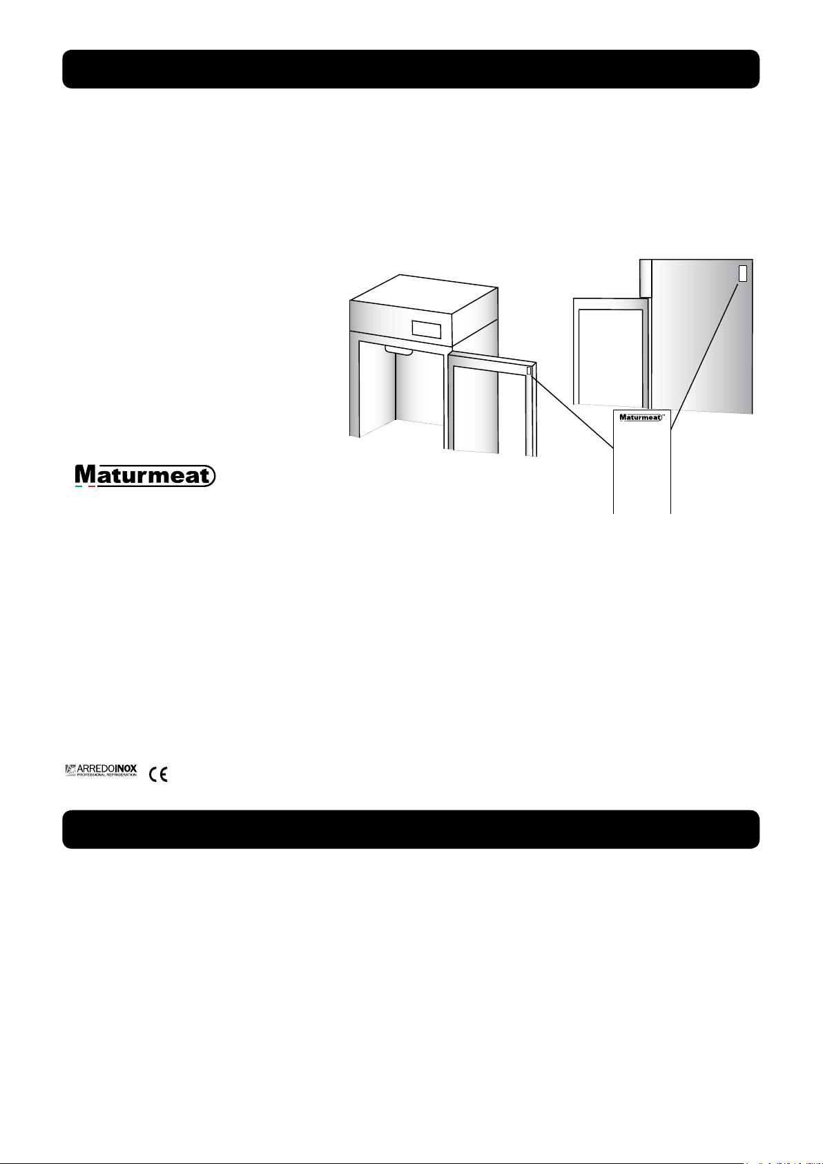
The serial tag is a permanently afxed sticker on which is recorded vital electrical and refrigeration data about your Maturmeat® product, as well as the model and serial number. There are
two data plates on each unit, they can be found on the inside top corner of the doorframe
and on the top corner on the right hand side of the body. When contacting the manufacturer,
please provide the serial number and production lot number found on your cabinet or on the
conformance certicate.
1) Brand
2) Model
3) Serial number
4) Production lot number
5) Voltage
6) Frquency
7) Max Power
8) Nominal Power
9) Power usage for lighting
10) Power usage during heating
11) Power usage during air cycling
12) Power usage during cooling
13) Power usage during humidication
14) Power usage during dehumidication
15) Power usage during avouring
16) Power usage during defrosting
17) Refrigerant type
18) Refrigerant quantity
19) Climatic class
20) Max operating current
21) Compressor Rated load Amps
22) Manufacturer
23) Certication
24) Country of Origin
1.3
The following items are included with your Maturmeat®. Contact your dealer should any of the
following be missing
No. 3 temperature probes;
No. 1 humidity probe;
No. 1 closed loop connector (for direct waterline see page 25);
No. 1 replacement tubes for aroma pump (2 for Twin 100+100);
No. 1 user manual;
No. 1 warranty registration card;
No. 1 drain tray (except 60);
No. 1 drain hose;
No. 5 guide sets (L&R); (10 for 200 & Twin 100+100)
No. 5 stainless steel shelves (10 for 200 & Twin 100+100)
4
STANDARD ACCESSORIES
Rev 2, 18.06.19
Page 5
1.4
MODEL 60
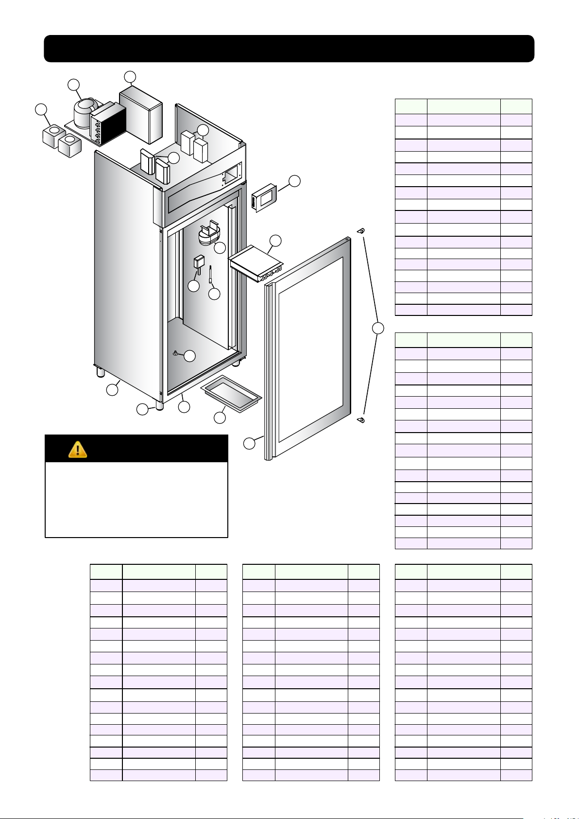
MATURMEAT® DIAGRAM
2
3
1
5
9
11
12
13
14
DANGER
Gas Exposure
Do not damage the cooling system as it contains R404a refrigerant, which can cause injury, burns
and frostbite.
MODEL 150 MODEL 200 MODEL TWIN100+100
Number Description Quantity
1
Tanks water/aroma
2
Condensing Unit
3
Fumotic®
4
Transformer
5
PLC
6
Touch Controller
7
Evaporator
8
Internal Light
9
Humidity Probe
10
Ambient Probe
11
Steam Output
12
Unibody Frame
13
Adjustable Legs
14
Molding w/Heating
15
Drain Tray
16
Door w/Resistance
17
Door Hinge
Number Description Quantity
1
Tanks water/aroma
4
6
8
7
10
15
16
Number Description Quantity
2
1
1
2
2
1
2
1
1
1
1
1
4
1
1
1
2
1
Tanks water/aroma
2
Condensing Unit
3
Fumotic®
4
Transformer
5
PLC
6
Touch Controller
7
Evaporator
8
Internal Light
9
Humidity Probe
10
Ambient Probe
11
Steam Output
12
Unibody Frame
13
Adjustable Legs
14
Molding w/Heating
15
Drain Tray
16
Door w/Resistance
17
Door Hinge
17
2
1
1
2
2
1
2
1
1
1
2
1
4
1
1
2
4
2
Condensing Unit
3
Fumotic®
4
Transformer
5
PLC
6
Touch Controller
7
Evaporator
8
Internal Light
9
Humidity Probe
10
Ambient Probe
11
Steam Output
12
Unibody Frame
13
Adjustable Legs
14
Molding w/Heating
15
Drain Tray
16
Door w/Resistance
17
Door Hinge
MODEL 100
Number Description Quantity
1
Tanks water/aroma
2
Condensing Unit
3
Fumotic®
4
Transformer
5
PLC
6
Touch Controller
7
Evaporator
8
Internal Light
9
Humidity Probe
10
Ambient Probe
11
Steam Output
12
Unibody Frame
13
Adjustable Legs
14
Molding w/Heating
15
Drain Tray
16
Door w/Resistance
17
Door Hinge
2
1
1
2
2
1
1
1
1
1
1
1
4
1
1
2
4
2
1
1
2
2
1
1
1
1
1
1
1
4
1
1
1
2
2
2
1
4
4
2
2
1
2
2
2
1
4
1
1
2
4
5
Rev 2, 18.06.19
Page 6
1.5
All Maturmeat® units are factory tested for performance and are free from defects when
shipped. The utmost care has been taken in crating this product to protect against damage in
transit.
You should carefully inspect your Maturmeat® unit for damage during delivery, even if the crate
is free from damage. If damage is detected, you should save all the crating materials and make
note on the carrier’s Bill Of Lading describing this. A freight claim should be led immediately. If
damage is subsequently noted during or immediately after installation, contact the respective
carrier and le a freight claim. Under no condition may a damaged unit be returned without rst
obtaining written permission (return authorization).
RECEIPT INSPECTION
1.6
DANGER
Excessive Weight Hazard
Use two or more people to move
and install your Maturmeat®.
Failure to do so can result in back
or other injury.
INSTALLATION
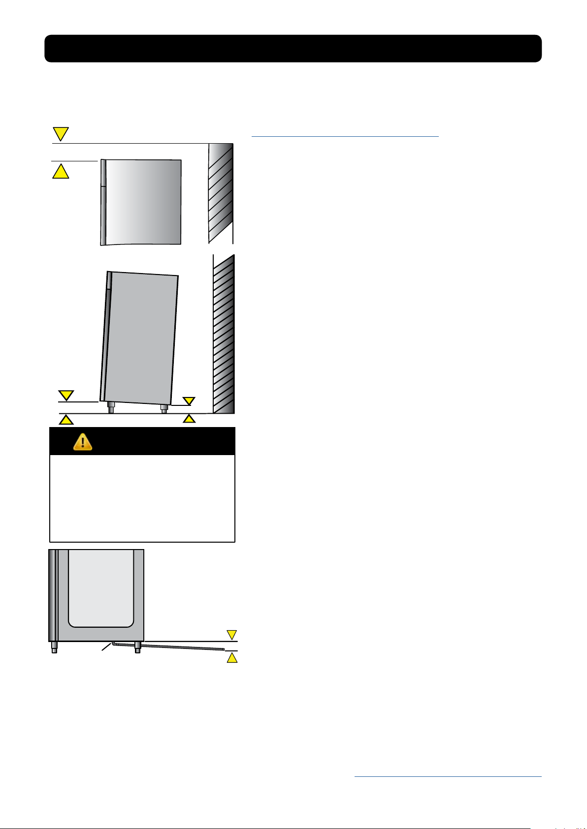
LOCATION:
Select a proper location away from extreme heat or
cold. Space above the unit should allow for breathability to the condensing unit and access to the Water/
Aroma tanks. Allow enough clearance between the
unit and the side wall in order to allow the doors to fully
open.
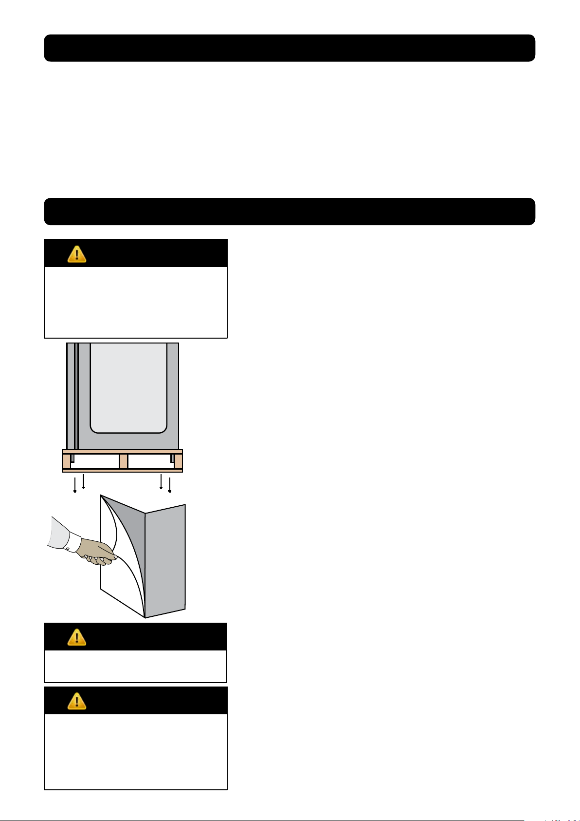
PACKAGING:
The unit is shipped from the factory strapped to a sturdy wooden pallet and protected by MDF crating. The
crating is attached to the pallet with nails and several
screws. These should rst be removed to avoid scratching the unit when lifting off the crating. To remove the
Maturmeat® from the wooden pallet start by cutting
free the nylon bands. There are 4 bolts connecting the
Maturmeat® to the pallet, remove them to release the
Maturmeat® from the pallet.
Most exterior surfaces have a protective vinyl covering
to prevent scratching during manufacturing, shipping,
and installation, remove after installation and discard.
DANGER
Keep all packaging away from
children
DANGER
Electrical Hazard
Never connect power to unit
via extension cord or adapter,
this can cause damage to the
system and/or start a re.
6
NOTE: DO NOT LAY THE UNIT ON ITS SIDE/BACK/FRONT
DURING TRANSPORTATION OR INSTALLATION.
POWER CORD:
An attached power cord is provided without plug,
shipped coiled inside the compressor compartment.
For your safety and protection, have the installer connect the proper plug for your country by checking with
the information on the data plate. Connect only to an
appropriate dedicated 20 amp outlet.
POWER SUPPLY:
The supply voltage should be checked prior to connection to be certain that proper voltage for the cabinet
wiring is available (refer to the data plate for the correct
unit voltage). Make connections in accordance with local electrical codes. Use qualied electricians.
Use of a separate, dedicated circuit is required.
Size wiring to handle indicated load and provide necessary overcurrent protector in circuit (see amp requirements on the unit’s data plate).
Rev 2, 18.06.19
Page 7
INSTALLATION continued
Connection
Point
ELECTRICAL SCHEMATICS:
Refer to the electrical schematics on page 46-52 for any
service work performed on the unit. Should you require
a new one, please contact Maturmeat® Service at
ufcioqualita@stagionellostore.com, and provide serial
number of the unit involved.
CLEARANCE:
To assure optimum performance of your Maturmeat®
the condensing unit MUST have an adequate supply of
air for cooling purposes. The operating location must
have 45 cm (18”) minimum clearance from the top of
the Maturmeat® to the ceiling.
Select a working location away from extreme heat or
cold. The Maturmeat® is designed to operate in temps
of 32°C (89°F) or less. Locate the unit so that air drafts
(such as heat, A/C or ventilation) do not blow on or over
the top of the Maturmeat®.
ADJUSTING LEGS:
Unit includes 4 factory installed (except 100kg model).
The ideal position for the unit should be that it leans
towards the back, to allow for proper door closure.
Adjust the leg by turning the lower portion of the leg.
MATC100TF units will include 4 legs and 16 bolts packed
inside the unit, these will need to be mounted and then
adjusted.
VISUAL TEST:
DANGER
Electrical Shock Hazzard
if any damage to wiring is found,
do not touch and contact your
local service point. Failure to do
so can result in serious injury or
death.
REGISTER YOUR UNIT:
Once your Maturmeat® has been installed by an authorized technician, validate the
warranty by sending an e-mail to the following address ufcioqualita@stagionellostore.com
enclosing the installation worksheet.
Check the top of the unit making sure nothing has
moved, shifted or loosened during transport. Check that
all wires to PLC’s are rmly connected, check lines on
the condensing unit, check Fumotic® and lines to tanks.
Disconnect power to unit before performing visual test
PREPARE UNIT:
Fill the water tank with water to avoid false alarm. Slide
the drain tray on the tracks underneath the unit, or set up
the drain hose to connect to a oor or dedicated drainage system. Make sure that the end of the drain hose
is a minimum of 5cm lower than the connection point.
Before starting the test recipe, wipe down the inside of
the unit in contact with food using a cloth or sponge,
water and a non aggressive/non abrasive cleaner (for
more information on cleaning, refer to page 26).
TEST RECIPE:
Maturmeat® has a test recipe programmed under the
My Recipe category. The test recipe must be run to ensure the Maturmeat® performs all its functions. This is to
prevent loss of product on rst use. To set test recipe see
page 9
Rev 2, 18.06.19
7
Page 8

®
®
2.1
USING SICUR FOOD CONTROL
FOR THE FIRST TIME
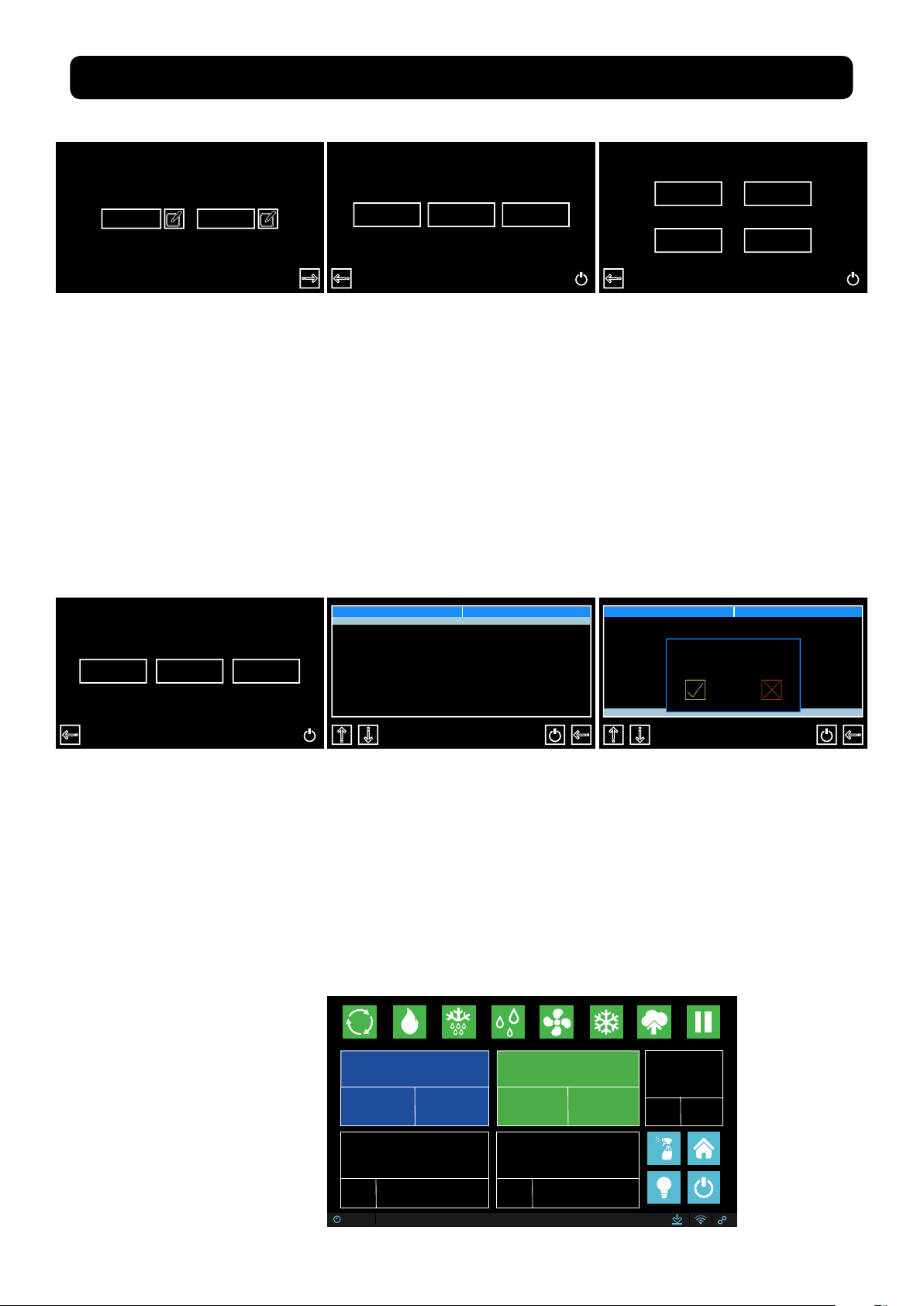
After a successful installation and with power to your Maturmeat®, the Sicur Food Control® controller will start up automatically on the Welcome page.
The Welcome page allows you to select the language, and displays Firmware version installed.
Note: Information may be displayed in Italian for the rst time
From this screen, select the language
you would like to use. You can change
language at anytime by pressing the
Welcome
24/03/2018 12:35
backward arrow from the Home page.
If needed, come back to the welcome
page to check your rmware version,
which can be found in the bottom left
corner of the screen.
Serial
10002156, FW.1.13, PLC-A1.37, PLC-B1.37
Patent #1395586 - Climatouch
After selecting your language, you
will land on the date and time page,
where you can adjust the data should
you need to.
To adjust the date or time, press the Set
icon beside the corresponding eld.
Use the up and down arrows above
and below the numbers to adjust the
month, day and year. Press the check
mark to save and exit.
24/03/2018
24/03/2018
24 03 2018
12:35
12:35
Use the up and down arrows above
and below the numbers to adjust the
hour and minute. Press the check mark
to save and exit.
24/03/2018
12 35
12:35
8
Rev 2, 18.06.19
Page 9
2.2
STARTING THE TEST RECIPE
24/03/2018
12:35
1. After setting date & time,
press forward arrow.
Customer Dealer Producer
2. This is the Home page, here
you have 3 options to choose
from:
i. Customer,
ii. Dealer,
iii. Producer,
Select Customer to proceed.
Recipe list Recipe list
3. In the customer area, you
have 4 options to choose from:
i. Climatic Recipes
ii. HACCP-Performance
iii. pH calbr.
iiii. Variables
Select Climatic Recipes.
Climatic recipes
pH calibr.
HACCP-Perf
Variable
My recipe Def. recipes Create a recipe
4. On the recipes page
you can access all recipes;
here you have 3 options to
choose from:
i. My Recipes
ii. Default Recipes
iii. Create a Recipe
Select My recipes.
7. The test recipe should
automatically start. Look at
the start/pause button to
make sure itsn’t ashing.
Test Recipe
5. The test recipe is found at
the bottom of the list; press
the downward arrow until
you see the recipe.
Current Recipe
Test Recipe
TOTAL TIME
12 Hrs
REMAING TIME
TEMPERATURE
TOTAL TIME2REMAING TIME
11 Hrs
PHASE 1 OF 1
Heat
HUMIDITY
Ongoing recipe !
Start new ?
Test Recipe
6. With the test recipe
Highlighted, press the start
button. A message will
appear, press the check
mark button to proceed.
PH
5.8
1
SET
POINT
5.0
21.1˚C
SET
POINT
12:35 24/03/2018
25.0˚C
Rev 2, 18.06.19
SET
POINT
18
5%
%
9
Page 10
2.3
81%
5.8
1.0˚C
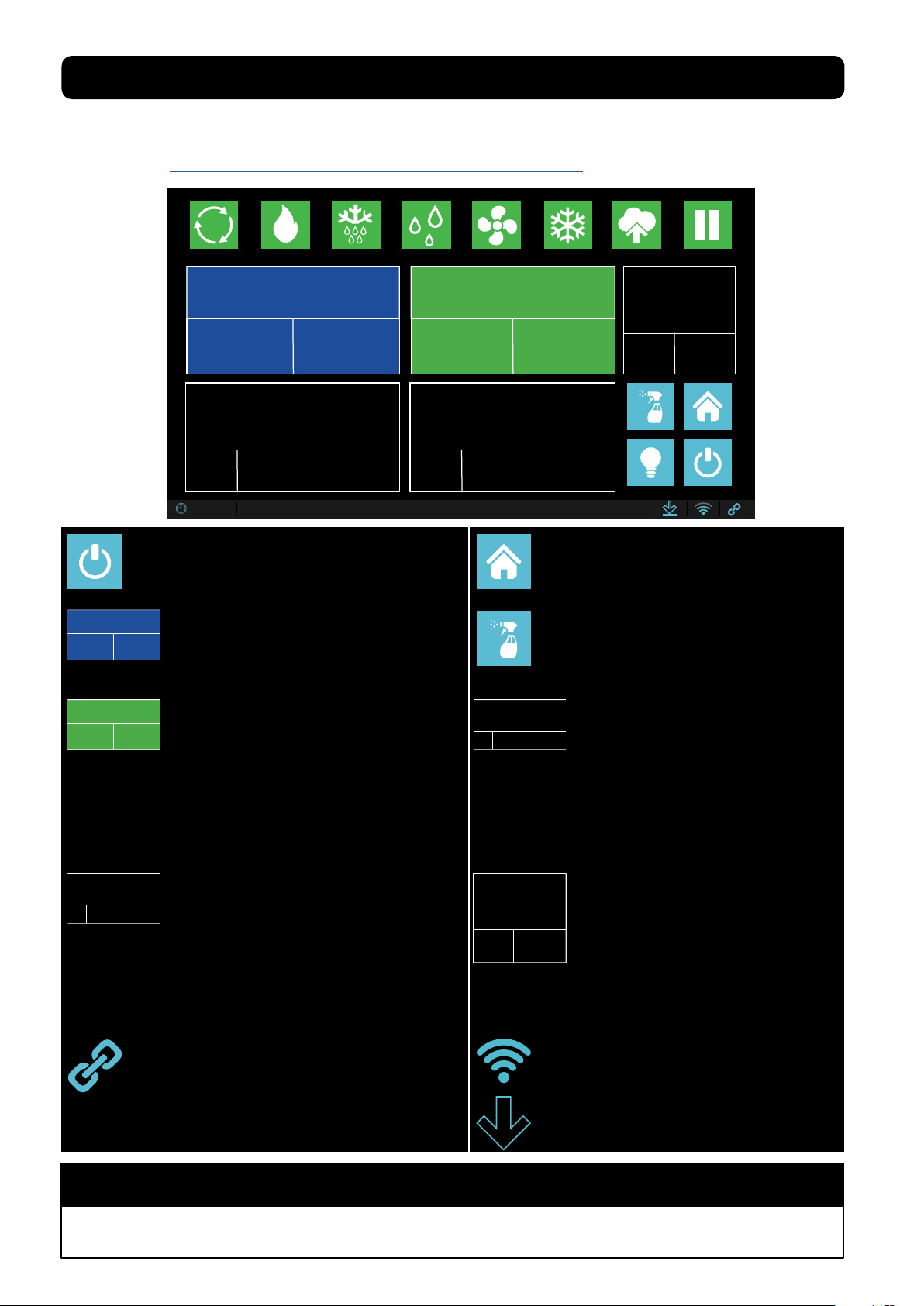
RECIPE SCREEN DEFINED
The following is an explaination of the recipe screen to help you understand the parameters you
will be interacting with daily on the Maturmeat® controller. Alternatively, use the link to see the
video online https://www.youtube.com/watch?v=AfhtshDWTdI
Current Recipe
AGED BEEF
TOTAL TIME
999 Hrs
TEMPERATURE
REMAING TIME
999 Hrs
TOTAL TIME
999
1.3˚C
SET
POINT
12:35 24/03/2018
Start/Pause Recipe:
Icon Light Blue = recipe is working.
Icon Grey = recipe is paused.
Current Recipe
AGED BEEF
TOTAL TIME
999 Hrs
PHASE 1 OF 1
MATURING
TOTAL TIME
999
Note: set yellow value to 0 to skip phase when necessary.
Recipe name currently in use.
REMAING TIME
Total time of the current recipe in use.
999 Hrs
Remaining time of the recipe in use.
Recipe phase currently preforming
REMAING TIME
WHITE VALUE: displays time remaining
999
in current phase.
YELLOW VALUE: displays total time in
current phase.
1.0˚C
SET
POINT
PHASE 1 OF 1
PH
MATURING
REMAING TIME
HUMIDITY
75
999
%
5.6
SET
POINT
5.8
81%
Home icon: has 2 functions, exit recipe
(when recipe is paused), check VTE/VTC
values (while recipe is working).
Cleaning In Place (C.I.P.): a 2 stage
recipe for internal washing and drying of
the chamber.
Note: remove all foodstuff before starting.
TEMPERATURE
1.3˚C
SET
Note: There is +/- 2 range. Temp must be achieved
before any other functions will work. It is normal to see
humidity go out of range during cooling/heating.
Temperature for current phase
WHITE VALUE: displays current temp
inside unit.
YELLOW VALUE: displays temp set
point needed to be reached.
HUMIDITY
75
SET
Note: There is +/- 7 range. Temp must be achieved before
any other functions will work. It is normal to see humidity go
out of range during cooling/heating.
Note: In order for the Link icon to be active, you must add
a GSM sim card to the controller.
Relative Humidity for current phase
%
WHITE VALUE: displays current humidity
inside unit.
YELLOW VALUE: displays humidity set
point needed to be reached.
Link turns blue only when a live connection
exists between controller and our server,
otherwise icon will be grey.
PH
5.6
SET
POINT
*This value can only be read when pH probe has been
purchased and connected.
pH for current phase (guide only)
*WHITE VALUE: displays current pH
value inside unit.
YELLOW VALUE: displays ideal value
to be reached.
Shows GSM connection strength in blue,
icon will be grey without connection.
Turnes blue when downloading
rmware, otherwise icon will be grey.
NOTE
Yellow value can be changed for the duration of the phase only, default values will reset once recipe
advances into the next phase, if recipe is exited and re-entered, or if power loss occurs.
10
Rev 2, 18.06.19
Page 11
RECIPE SCREEN DEFINED continued
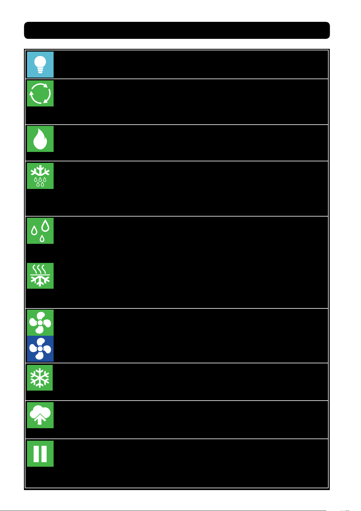
Internal Light:
If the icon is light blue and the frame ashing, this indicates the light inside the unit is
switched on.
Air Cycling:
If the icon is green and the frame ashing, this indicates that the air inside the unit is
being equalized to reduce cool/warm spots. All functions will be disabled for a set
period of time. It is normal for the temp and humidity to go out of range during this
time. The same key gives you the possibility of disabling or forcing an air cycle.
Heating:
If the icon is green and the frame ashing, this indicates that the heating system is
working to bring the temp up to the set point. The same key gives you the possibility
of disabling or forcing the action.
Defrost:
If the icon is green and the frame ashing, this indicates that the evaporator probe
has detected a temp (set in the system variables) and has triggered a defrost. All
functions will be disabled during the defrost period. It is normal for the temp and
humidity to go out of range during this time. The same key gives you the possibility of
disabling or forcing the action.
Humidication:
If the icon is green and the frame ashing, this indicates that humidication system is
working to bring the RH up to the set point. The same key gives you the possibility of
disabling humidication. Note when the unit needs to dehumidify, the humidication
icon will change to the dehumidication icon.
Dehumidication:
If the icon is green and the frame ashing, this indicates that dehumidication system
is working to bring the RH down to the set point. The same key gives you the possibility
of disabling dehumidication. Note when the unit needs to humidify, the dehumidi-
cation icon will change to the humidication icon.
Fan low/high speed:
If this icon is green with the green frame ashing, this indicates that the fan is working
at a low speed; if the icon is blue with blue ashing frame, this indicates that the fan is
working at a high speed. Note you can toggle between high and low speed setting
simply by pressing the fan icon.
Cooling:
If the icon is green and the frame ashing, this indicates that cooling system is
working to bring the temp down to the set point. The same key gives you the
possibility of disabling or forcing the action.
Aroma:
If the icon is green and the frame ashing, this indicates that liquid is drawn out of the
®
aroma tank by the Fumotic
you the possibility of disabling or forcing the action.
, nubulized and sprayed into the unit. The same key gives
Rest/Recovery:
If the icon is green and the frame ashing, this indicates that the Maturmeat® has
disabled all functions for a set period of time to allow the product inside to rest. It is
normal for the temp and humidity to go out of range during this time. The same key
gives you the possibility of disabling or forcing the action.
Rev 2, 18.06.19
11
Page 12
2.4
81%
STARTING A DEFAULT CLIMATIC RECIPE
Follow the steps below to start a default climatic recipe. Alternatively, use the link to see the
video online https://www.youtube.com/watch?v=TPEB3mqgs7M
Customer Dealer Producer
1. From the Home page,
Select Customer to proceed.
Recipe list
Aged Beef
Aged Game
Aged Deer
Aged Horse
R.Mortis
4. On this page you will nd
a list of 5 preset climatic
recipes. Press the recipe
name or use the down icon
until you see the recipe you
want to use.
Climatic recipes
pH calibr.
HACCP-Perf
Variable
2. Select Climatic Recipes.
Recipe list
Aged Beef
Aged Game
Aged Deer
Aged Horse
R.Mortis
Ongoing recipe !
Start new ?
5 . W i t h y o u r r e c i p e
highlighted, press the start
button, a message will
apear, press the check
mark button to proceed.
My recipe Def. recipes Create a recipe
3. Select Default Recipes
Current Recipe
AGED BEEF
TOTAL TIME
999 Hrs
TEMPERATURE
1.3˚C
SET
POINT
12:35 24/03/2018
REMAING TIME
999 Hrs
1.0˚C
TOTAL TIME
SET
POINT
999
PHASE 1 OF 1
MATURING
REMAING TIME
HUMIDITY
75
81%
999
%
5.6
SET
POINT
6. Your selected recipe
should automatically start.
Look at the start / pause
button to make sure its light
blue and ashing.
PH
5.8
2.5
MODIFING RECIPE PARAMETERS
Your production should be monitored daily, you may need and probably will have to, modify a
recipe at some point, this could be due to several factors (meat type, meat quality, etc.). Follow
the steps below to modify Time, Temp and Humidity parameters.
Modications to default/saved recipes while in course are temporary and will last until the end
of the phase, once the phase changes the parameters are returned to their preset value.
78
HUMIDITY
75
%
SET
POINT
1. To change a set point,
press the number in Yellow.
Current Recipe
AGED BEEF
TOTAL TIME
REMAING TIME
999 Hrs
SET
POINT
12:35 24/03/2018
999 Hrs
TEMPERATURE
1.3˚C
1.0˚C
2. The keypad will appear,
enter your value and press
OK to temporarily save.
Esc
1
4
7
-
.
TOTAL TIME
SET
POINT
999
PHASE 1 OF 1
OK
MATURING
2 3
5 6
HUMIDITY
75
8 9
81%
0 C
REMAING TIME
999
%
5.6
SET
POINT
PH
5.8
Current Recipe
AGED BEEF
TOTAL TIME
999 Hrs
TEMPERATURE
1.3˚C
SET
POINT
12:35 24/03/2018
REMAING TIME
999 Hrs
1.0˚C
TOTAL TIME
SET
POINT
999
PHASE 1 OF 1
MATURING
REMAING TIME
HUMIDITY
75
78%
999
%
5.6
SET
POINT
PH
5.8
3. The recipe will continue
with the new modied value
until the end of the phase.
12
Rev 2, 18.06.19
Page 13
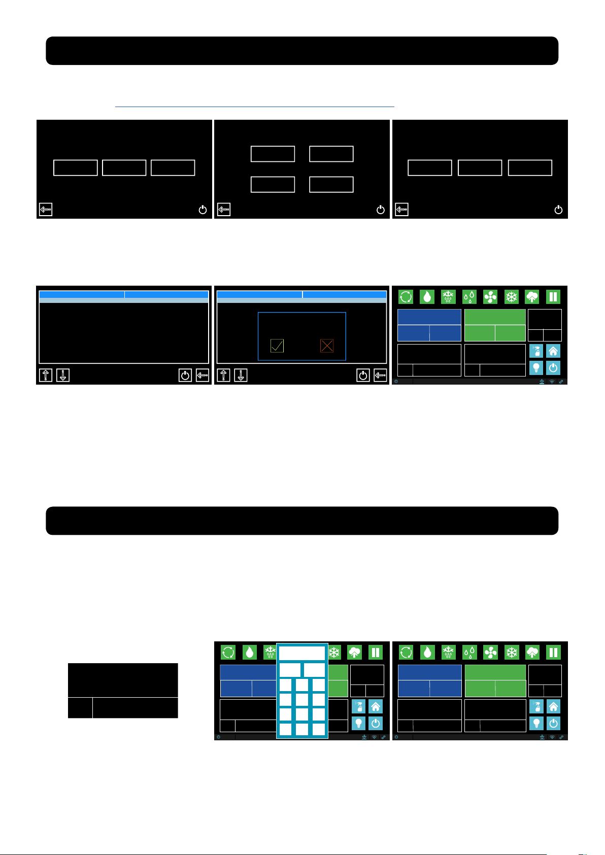
2.6
H
CHECKING HACCP-PERFORMANCE AS LINE DATA
Customer Dealer Producer
1. From the Home page,
Select Customer to proceed.
Home Icon:
Pressing the home icon exits the HACCP-Performance page and returns you to the
home page
R Icon:
R
Displays production data in line form. Press the R and it turns to an H.
Note: while in R mode you cannot access the graphs, for this you must be in H mode
H Icon:
Displays the same production data (in green font), this data cannot be printed. At
this point you can press graph icon to change to graph view.
Climatic recipes
pH calibr.
HACCP-Perf
Variable
2. Select HACCP-Pref.
Date Time
10/06/2018
10/06/2018
10/06/2018
10/06/2018
11/06/2018
11/06/2018
11/06/2018
11/06/2018
11/06/2018
11/06/2018
12/06/2018
10:32
14:32
18:32
22:32
02:32
06:32
10:32
14:32
18:32
22:32
02:32
C RH
˚
1.5
2.3
3.4
2.9
2.4
1.1
1.9
1.7
2.3
3.1
1.2
pH
5.9
˚C
76
6.0
75
6.0
78
6.0
80
6.1
78
6.1
81
6.1
76
6.1
88
6.2
79
6.2
75
6.2
R
3. Here you can search, view
and print production data.
Graph Icon:
Graph layout of line data can be viewed here, if your contoller is connect to our
cloud, this data can be downloaded.
Print Icon:
Line data can be printed via a specialized handheld printer purchased through your
Stagionello™/Maturmeat® distributor.
Trash Icon:
Delete line data.
Search Icon:
Line data can accumulate quickly, use the search icon to advance to a specic
date.
Page Down Icon:
Quickly scroll down page by page.
Page Up Icon:
Quickly scroll up page by page.
Down Icon:
Scroll down one line at a time.
Up Icon:
Scroll up one line at a time.
13
Rev 2, 18.06.19
Page 14
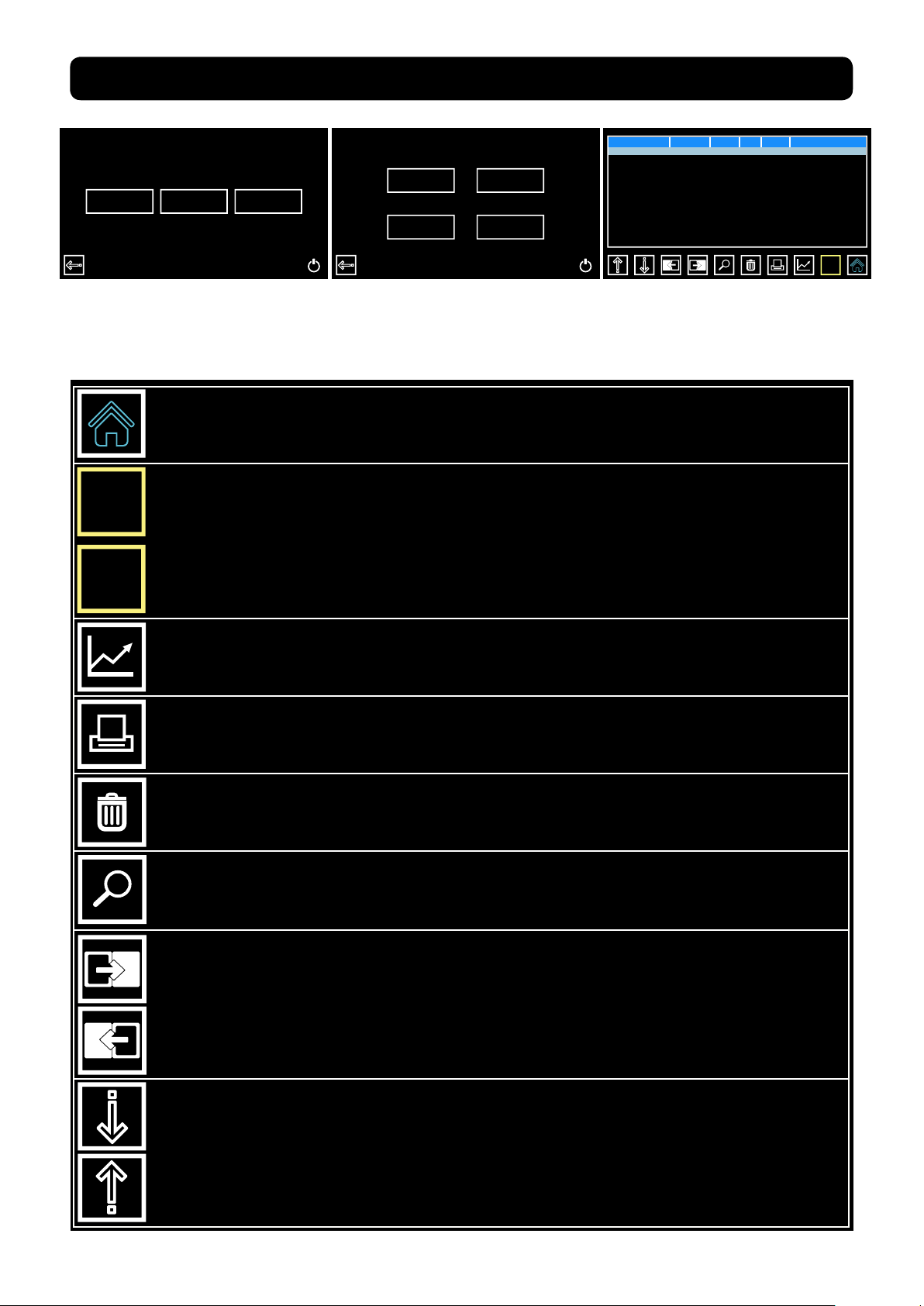
2.7
CHECKING HACCP-PERFROMANCE AS A GRAPH
Graph View:
After switching to H mode, you can now access your production data in the form of a graph by
pressing the graph icon. Temperature, Humidity and pH can be viewed here. You will notice that
the print icon has been replaced by an Eye icon, this will allow you to toggle between 3 graphs.
99
Temperature
12/04/2018 10:32
90
80
70
60
50
40
30
20
10
0
-10
-20
-30
-40
-50
Temperature
15/05/2018 14:32
12/04/2018 10:32
H
92
82
71
61
50
40
30
20
10
0
pH
15/05/2018 14:32
12/04/2018 10:32
H
14
13
12
11
10
9
8
7
6
5
4
3
2
1
0
H
15/05/2018 14:32
Temperature Graph
Home Icon:
Pressing the home icon exits the HACCP-Performance page and returns you to the
home page
H Icon:
H
While in graph view, pressing H will exit graph view and return you to R mode (line
data).
Eye Icon:
While in graph view, press the eye icon to toggle through the 3 graphs (Temp, Humidity, pH).
Trash Icon:
Delete data.
Search Icon:
Graph data can accumulate quickly, use the search icon to advance to a specic
date.
Humidity Graph
pH Graph
14
Forward Icon:
Advance forward to the next section data.
Backward Icon:
Move backward to the next section data.
Down Icon:
Has no functionality on graph view.
Up Icon:
Has no functionality on graph view.
Rev 2, 18.06.19
Page 15

2.8
NEW RECIPE PARAMETERS DEFINED
The following is an explanation to help you understand the parameters involved in creating a
new recipe on the Sicur Food Control® controller. Alternatively, use the link to see the video on-
line https://www.youtube.com/watch?v=-HKpifRFNWE
Create a recipe
Create Recipe Page 1.
Name
StageNbrs
Nuova Ricetta
8
On this page there are 2 sections to ll in:
1. Recipe Name
2. Number of sequential stages
Create Recipe Page 2.
There are 16 recipe variables to create:
1. Name: Phase Name.
2. Time: Number of hours this phase should last.
3. Temp(ºC): The average temperature that should be main-
Create a recipe Stage 1
Name
Time
Temperature(˚) 20.0
Humidity(Rh) 50
PH 7.0
Ventilation H 0
Aroma Length(m) 0
Per.Aroma(h) 0
Phase 1
10
tained during this phase.
4. Humidity: The average humidity that should be maintained
during this phase.
5. Ventilation: Fan speed 0 = low speed, 1 = high speed.
6. PH: by setting a value here, you are creating a guideline. Note: in order for the Sicur Food Control®
to read pH data in your product, the optional pH probe must be connected to the Maturmeat®.
7. Aroma length(m): by setting a value here, the liquid in the aroma tank will be drawn into the Fumotic® and will be nebulized and sprayed into the unit for the length of time (in minutes) set by you.
8. Per.Aroma(h): by setting a value here, you are setting the number of hours between each aroma
activation.
9. Recovery length(m): all functionality is shut down to allow the product inside time to rest, this variable represents the amount of time in minutes that the rest/recovery will last.
10. Recovery period(h): this variable sets the number of hours between each rest/recovery period.
11. Recycle length(s): all functionality is shut down and the air inside is cycled in an attempt to
equalize the climate, this variable represents the amount of time in seconds that the air cycle will
last.
12. Recycle period(m): this variable sets the number of minutes between each air cycling period.
13. Airenew length(m): all functionality is shut down and the air inside is ushed out and fresh air is in-
troduced into the unit, this variable represents the amount of time in minutes that the air exchange
will last.
14. Airenew period(h): this variable sets the number of hours between each air exchange period.
15. Overtime(h): this variable extents the phase in case extra time is needed.
Rev 2, 18.06.19
15
Page 16
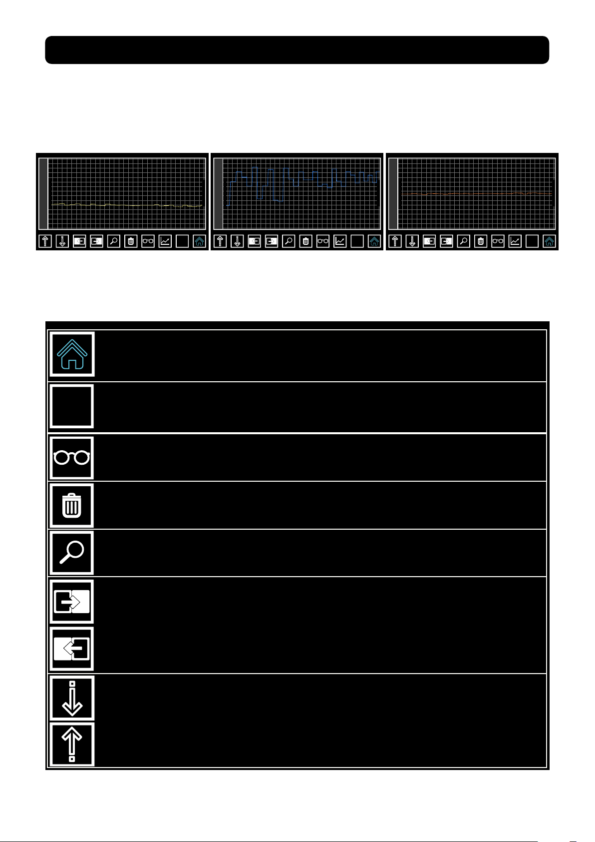
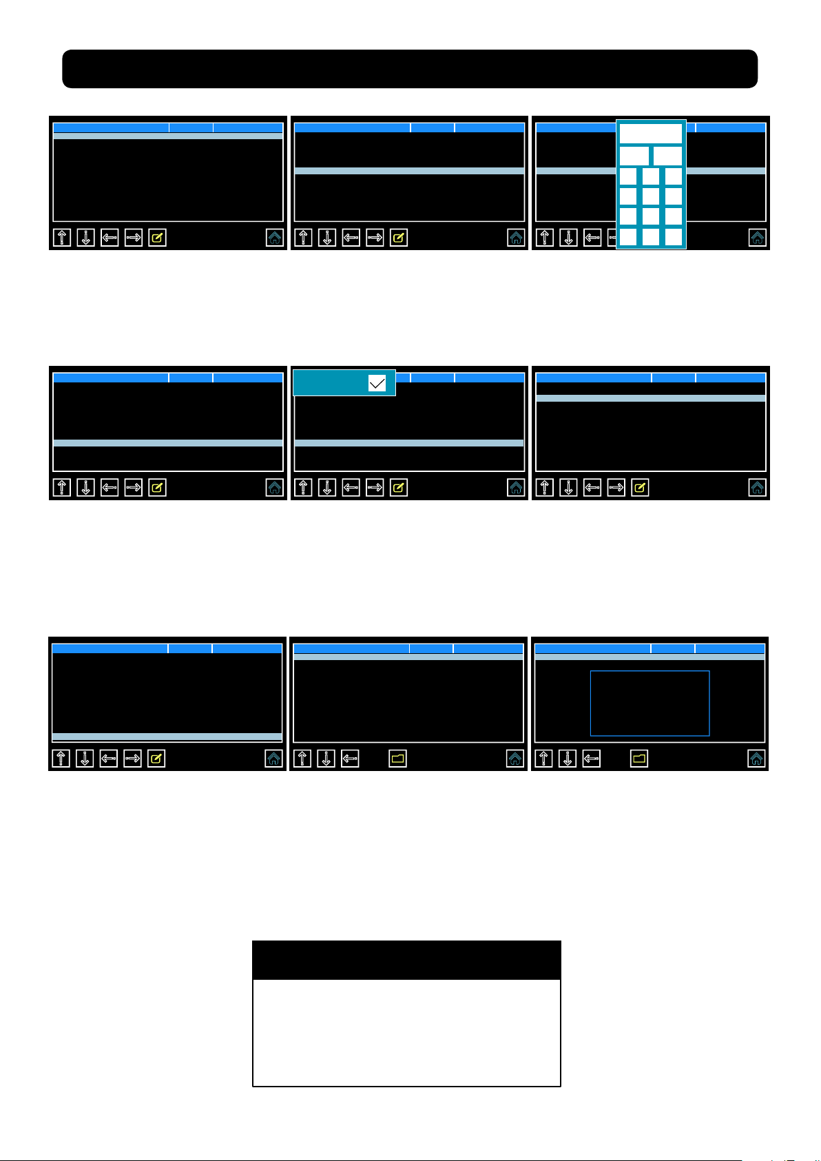
2.9
CREATING AND SAVING NEW RECIPES
This guide will help walk you through the process of creating and saving your own recipe. Alternatively, use the link to see the video online https://www.youtube.com/watch?v=FQfpGkWbeNs
The 3 tools you will use to
modify the recipe parameters
are:
Customer Dealer Producer
1. From the Home page,
Select Customer to proceed.
Create a recipe
Name
StageNbrs
Nuova Ricetta
8
Nuova Ricetta OKEsc
iuytrewq
kjhgfdsa
Del><mnbvcx
Shift Num
Shift
Keyboard Keypad Check box
Climatic recipes
pH calibr.
HACCP-Perf
Variable
2. Select Climatic Recipes.
Create a recipe
Name
StageNbrs
Shift Num
Shift
Nuova Ricetta
My Dry Aged OKEsc
8
iuytrewq
kjhgfdsa
Del><mnbvcx
78
OK
po
zl
Esc
1
2 3
4
5 6
7
8 9
-
.
0 C
My recipe Def. recipes Create a recipe
Ventilation H
Ventilation H
3. Select Create a Recipe
Create a recipe
Name
StageNbrs
po
zl
My Dry Aged
8
4. With the name eld
higlighted in red, Press the
pencil icon to activate the
onscreen keyboard and set
your recipe name.
Create a recipe
Name
StageNbrs
Esc
1
4
7
-
.
My Dry Aged
8
OK
2 3
5 6
8 9
0 C
1
7. Enter the number of stages
you want to your new recipe
to have and press OK. If all
the information you have
entered is correct press the
forward arrow to advance to
the next page.
16
5. Use delete key to empty the
eld, type the name of your
new recipe and press OK.
Create a recipe Stage 1
Name
Time
Temperature(˚) 20.0
Humidity(Rh) 50
PH 7.0
Ventilation H 0
Aroma Length(m) 0
Per.Aroma(h) 0
Phase 1
10
8. On this page you have *16
elds that can be modied
(*with the exception of Free
Variable this should be left 0).
With the name eld highlighted in red, press the pencil icon
to activate the keyboard and
set the name for this stage.
Rev 2, 18.06.19
6. Use the down arrow to
highlight the next eld, press
the pencil icon to activate
the keypad to select the
number of stages you want
your recipe to have.
Create a recipe Stage 1
Name
Time
Temperature(˚) 20.0
Humidity(Rh) 50
PH 7.0
Ventilation H 0
Aroma Length(m) 0
Per.Aroma(h) 0
Shift Num
Shift
Phase 1
Maturing OKEsc
10
iuytrewq
po
kjhgfdsa
zl
Del><mnbvcx
9. Use delete key to empty
the eld, type the name of
this stage and press OK.
Page 17
CREATING AND SAVING NEW RECIPES continued
Create a recipe Stage 1
Name
Time
Temperature(˚) 20.0
Humidity(Rh) 50
PH 7.0
Ventilation H 0
Aroma Length(m) 0
Per.Aroma(h) 0
Maturing
10
10. Use the down arrow to
scroll through the recipe
parameters, one by one,
and adjust according to your
needs.
Create a recipe Stage 1
Name
Time
Temperature(˚) 1.5
Humidity(Rh) 75
PH 7.0
Ventilation H 0
Aroma Length(m) 0
Per.Aroma(h) 0
Maturing
999
13. The ventilation or fan
speed has 2 settings:
0 = low speed
1 = high speed
Press the pencil icon to
activate the check box.
Create a recipe Stage 1
Name
Time
Temperature(˚) 1.5
Humidity(Rh) 50
PH 7.0
Ventilation H 0
Aroma Length(m) 0
Per.Aroma(h) 0
Maturing
999
11. You can skip ahead
somewhat by pressing on the
parameter to highlight it.
Create a recipe Stage 1
Ventilation H
Name
Time
Temperature(˚) 1.5
Humidity(Rh) 75
PH 7.0
Ventilation H 0
Aroma Length(m) 0
Per.Aroma(h) 0
Maturing
999
14. By pressing on the empty
box you will place a check
mark inside, setting the fan on
high-speed for this stage when
needed.
Create a recipe Stage 1
Name
Time
Temperature(˚) 1.5
Humidity(Rh) 50
PH 7.0
Ventilation H 0
Aroma Length(m) 0
Per.Aroma(h) 0
Esc
1
4
7
75
Maturing
999
OK
2 3
5 6
8 9
-
.
0 C
12. For the majority of the
parameters, you will be
working with the keypad to
modify its value.
Create a recipe Stage 1
Per.Aroma(h)
Recov. length(m)
Recov. period(h) 2
Recov. length(s) 300
Recov. period(m) 120
Recov. length(m) 5
Recov. period(h) 12
Overtime(h) 0
0
30
15. The following Parameters
can be left as is:
Recov
Recycl
Airenew
Create a recipe Stage 1
Per.Aroma(h)
Recov. length(m)
Recov. period(h) 2
Recov. length(s) 300
Recov. period(m) 120
Recov. length(m) 5
Recov. period(h) 12
Overtime(h) 0
0
30
16. Once nished the current
page, press the forward
arrow to advance to the
next page and repeat steps
8 - 15. Once you have lled
in all parameters for all stages
press the forward arrow to
advance.
Save recipe Position
...
...
... 3
... 4
... 5
... 6
... 7
... 8
1
2
17. Once on the save recipe
page, select the position to
place your recipe and press
the disk button to save.
Save recipe Position
...
...
... 3
... 4
... 5
... 6
... 7
... 8
18. A save in progress message will appear onscreen
and may last a short while.
Once save is complete you
will automatically be returned
to the Home page.
NOTE
The Aroma parameters are connected
®
directly to the Fumotic
tank, if you do not use liquid avoring (ie.
Natural liquid smoke) in your recipe set
the values to 0 to avoid false alarms.
and the aroma
1
2
Please wait
Save in progress
Rev 2, 18.06.19
17
Page 18
2.10
STARTING A SAVED RECIPE
Follow the steps below to start a recipe that you have previously created and saved.
Customer Dealer Producer
1. From the Home page,
Select Customer to proceed.
Recipe List
My Dry Aged
...
...
...
...
...
...
...
4. Depending on how many
recipes you’ve created and
saved, you may have to use
the down arrow to select the
recipe you want.
Climatic recipes
pH calibr.
HACCP-Perf
Variable
2. Select Climatic Recipes
Recipe List
My Dry Aged
...
...
...
...
...
...
...
Ongoing recipe !
Start new ?
5. With your recipe highlighted
in red, press the start button,
a message will appear, press
the check mark button to
proceed.
My recipe Def. recipes Create a recipe
3. Select My Recipes
Current Recipe
My Dry Aged
TOTAL TIME
999 Hrs
TEMPERATURE
1.8˚C
SET
POINT
12:35 24/03/2018
REMAING TIME
999 Hrs
1.5˚C
TOTAL TIME
SET
POINT
Maturing
999
PHASE 1 OF 1
HUMIDITY
73
75%
REMAING TIME
999
%
6.4
SET
POINT
PH
6. Your selected recipe
should automatically start.
Look at the start / pause
button to make sure its
green.
7.0
2.11
FORCING AROMA
Follow the steps below to force aroma anytime during a default climatic recipe or a recipe that
you have previously created and saved.
Current Recipe
My Dry Aged
TOTAL TIME
999 Hrs
TEMPERATURE
1.8˚C
SET
POINT
12:35 24/03/2018
REMAING TIME
999 Hrs
1.5˚C
TOTAL TIME
SET
POINT
Maturing
999
PHASE 1 OF 1
HUMIDITY
73
75%
REMAING TIME
999
%
6.4
SET
POINT
PH
7.0
1. With your recipe running,
press the aroma icon, the time
selection box will appear
onscreen.
Current Recipe
My Dry Aged
TOTAL TIME
999 Hrs
SET
POINT
12:35 24/03/2018
REMAING TIME
999 Hrs
TEMPERATURE
1.8˚C
1.5˚C
12 35
2. Using the up and down
arrows, select the hours and/
or minutes that you want
liquid from the aroma /
Force Aroma
Maturing
TOTAL TIME
999
SET
POINT
PHASE 1 OF 1
HUMIDITY
73
75%
REMAING TIME
999
%
6.4
SET
POINT
PH
7.0
avor tank to be nebulized
®
by Fumotic
and sprayed
into the unit.
18
Rev 2, 18.06.19
Page 19

3.1
CALIBRATING STANDARD PROBES
Your Maturmeat® has 3 standard probes that can be calibrated by you or by a technician. The probes are checked thoroughly before your Maturmeat® leaves the factory.
A certied instrument to measure either humidity and/or temperature must be used to calibrate the probes on your Maturmeat®. Follow the steps below to access the variables
p a g e t o b e g i n c a l i b r a t i n g t h e p r o b e s , a l t e r n a t i v e l y , u s e t h e l i n k t o s e e t h e v i d e o o n l i n e
https://www.youtube.com/watch?v=TmPLBJ2aC4Q
Customer Dealer Producer
1. From the Home page,
Select Customer to proceed.
Var. Meaning
CORR. SONDA AMB.
CSA
CORR. SONDA U.
CSU
CORR. SONDA C.D
CSC
F.ZA MEM.HACCP
HACF
FAHRENHEIT
FAHR
ESCL.PSW USER
EPSU
PASSWD USER
PSWU
Esc
1
4
7
-
.
0.0
0
OK
0.0
240
2 3
0
0
5 6
1234
8 9
0 C
-3
˚C
Hg
˚C
m
D
D
*
4. Use the keypad to enter
the new value. The range of
values that can be set are
between -20…0…+20. Once
value is set press OK. Press the
folder / left facing arrow icon
to save and exit the variables
page.
Climatic recipes
pH calibr.
HACCP-Perf
Variable
2. Select Variables
Climatic recipes
pH calibr.
HACCP-Perf
Variable
5. Press the start icon to get
back to your recipe. Continue to take readings with the
two probes (Certied probe
and built-in Maturmeat®
probe) until both probes read
the same.
Var. Meaning
CORR. SONDA AMB.
CSA
CORR. SONDA U.
CSU
CORR. SONDA C.D
CSC
F.ZA MEM.HACCP
HACF
FAHRENHEIT
FAHR
ESCL.PSW USER
EPSU
PASSWD USER
PSWU
0.0
0
0.0
240
0
0
1234
˚C
Hg
˚C
m
D
D
*
3. On the variables page you
will nd 3 editable items:
i. CSA - Ambient temp probe
ii. CSU - Humidity probe
iii. CSC - Condenser probe
Highlight the variable and
press the pencil icon to
activate the keypad to select
the corrected value.
NOTE
Comparison readings should
be taken with the fan running
and with the fan on pause.
Take readings over a period
of 5-10min.
NOTE
Rev 2, 18.06.19
If you do not have a certied
or professionally calibrated
probe, please consult with a
professional for assistance.
19
Page 20

3.2
CHANGING HACCP RECORDING FREQUENCY
Your Maturmeat® can be modied in the to adjust to your needs. The HACCP recording
frequeny can be modied to allow you to validate your production.
Customer Dealer Producer
1. From the Home page,
Select Customer to proceed.
Var. Meaning
CORR. SONDA AMB.
CSA
CORR. SONDA U.
CSU
CORR. SONDA C.D
CSC
F.ZA MEM.HACCP
HACF
FAHRENHEIT
FAHR
ESCL.PSW USER
EPSU
PASSWD USER
PSWU
Esc
1
4
7
-
.
120
0.0
0
OK
0.0
240
2 3
0
0
5 6
1234
8 9
0 C
˚C
Hg
˚C
m
D
D
*
Climatic recipes
pH calibr.
2. Select Variables
Climatic recipes
pH calibr.
HACCP-Perf
Variable
HACCP-Perf
Variable
Var. Meaning
CORR. SONDA AMB.
CSA
CSU
CORR. SONDA U.
CSC
CORR. SONDA C.D
HACF
F.ZA MEM.HACCP
FAHRENHEIT
FAHR
ESCL.PSW USER
EPSU
PASSWD USER
PSWU
0.0
0
0.0
240
0
0
1234
˚C
Hg
˚C
m
D
D
*
3. On the variables page you
must look for HACF. Highlight
the variable and press the
pencil icon to activate the
keypad.
4. Use the keypad to enter
the new value. The range
5. Press the start icon to get
back to your recipe.
of values that can be set
are between 1……240 minutes (m). Once value is set
press OK. Press the folder/left
facing arrow icon to save
and exit the variables page.
3.3
CHANGING FROM CELCIUS TO FARENHEIT
Your Maturmeat® can be modied in the to adjust to your needs. You can simply and quickly
change from celcius to farenheit, by following the steps below.
Customer Dealer Producer
Climatic recipes
pH calibr.
HACCP-Perf
Variable
Var. Meaning
CORR. SONDA AMB.
CSA
CSU
CORR. SONDA U.
CSC
CORR. SONDA C.D
HACF
F.ZA MEM.HACCP
FAHRENHEIT
FAHR
ESCL.PSW USER
EPSU
PASSWD USER
PSWU
0.0
0
0.0
240
0
0
1234
˚C
Hg
˚C
m
D
D
*
1. From the Home page,
Select Customer to proceed.
20
2. Select Variables
Rev 2, 18.06.19
3. On the variables page you
must look for FAHR. Highlight
the variable and press the
pencil icon to activate the
check box.
Page 21

Var. Meaning
FAHR
CORR. SONDA AMB.
CSA
CORR. SONDA U.
CSU
CORR. SONDA C.D
CSC
F.ZA MEM.HACCP
HACF
FAHRENHEIT
FAHR
ESCL.PSW USER
EPSU
PASSWD USER
PSWU
CHANGING FROM CELCIUS TO FARENHEIT
0.0
0
0.0
240
1
0
1234
˚C
Hg
˚C
m
D
D
*
Climatic recipes
pH calibr.
HACCP-Perf
Variable
continued
4. By pressing on the empty
box you will place a check
5. Press the start icon to get
back to your recipe.
mark inside, locking in
Farenheit as the new unit of
measurement. Press the folder/left facing arrow icon to
save and exit the variables
page.
3.4
SETTING THE SCREEN LOCK
Whether your Maturmeat® is placed in an area where the public can touch it, or it may be you
don’t want any other staff member/s to be able to manipulate your Sicur Food Control® controller, you can protect your product and settings by setting a passcode protected screen lock.
Customer Dealer Producer
Climatic recipes
pH calibr.
HACCP-Perf
Variable
Var. Meaning
CORR. SONDA AMB.
CSA
CSU
CORR. SONDA U.
CSC
CORR. SONDA C.D
HACF
F.ZA MEM.HACCP
FAHRENHEIT
FAHR
ESCL.PSW USER
EPSU
PASSWD USER
PSWU
0.0
0
0.0
240
0
0
1234
˚C
Hg
˚C
m
D
D
*
1. From the Home page,
Select Customer to proceed.
Var. Meaning
EPSU
CSA
CSU
CSC
HACF
FAHR
EPSU
PSWU
CORR. SONDA AMB.
CORR. SONDA U.
CORR. SONDA C.D
F.ZA MEM.HACCP
FAHRENHEIT
ESCL.PSW USER
PASSWD USER
0.0
0
0.0
240
0
1
1234
˚C
Hg
˚C
m
D
D
*
4. By pressing on the empty
box you will place a check
mark inside, activating the
screen lock. Press the folder/
left facing arrow icon to save
and exit the variables page.
2. Select Variables
Climatic recipes
pH calibr.
HACCP-Perf
Variable
5. Press the start icon to get
back to your recipe.
3. On the variables page you
must look for EPSU. Highlight
the variable and press the
pencil icon to activate the
check box.
NOTE
The lock will reactive every 5
min after the last touch of the
screen.
NOTE
To set a custom passcode,
follow the same steps
highlighting PSWU instead.
The default passcode is 1234.
Rev 2, 18.06.19
21
Page 22

3.5
CALIBRATING pH PROBE
Your Maturmeat® has an optional pH probe that can be purchased. The probe is checked
thoroughly before your Maturmeat® leaves the factory. A calibration system has been
programmed into Sicur Food Control® allowing you the possibility to calibrate your pH probe
anytime. Follow the steps below to successfully calibrate your probe, alternatively, use the link
to see the video online https://www.youtube.com/watch?v=AkLgjoDq-G0
Here is what you will
need to calibrate the
pH probe
1. pH probe
2. Buffer solution 4.01
3. Buffer solution 7.01
4. Water (small amount)
5. Container x 3 (ie.cups)
6. Paper towel/Napkins
7. Marker to label cups
Because all of
the uids look
alike it is best to
pH 4 pH 7
label the cups to
avoid confusion
later on. Use the
marker and write
pH 4 or just 4 on
the 1st cup.
Buer
Solution
pH 4.01
On the 2nd cup,
use the marker
and write pH 7 or
just 7.
pH 4 pH 7 water
Buer
Solution
pH 7.01
On the 3rd cup,
use the marker
and write water or
just W. The water
will act as a rinse
between solutions.
water
NOTE
Rinse probe with water
between each recording of
buffer solutions. Use paper
towel/napkins with extreme
care when drying probe,
as probe’s surface can
easily scratch and become
damaged producing false
readings.
22
Customer Dealer Producer
1. From the Home page,
Select Customer to proceed.
Rev 2, 18.06.19
Climatic recipes
pH calibr.
2. Select pH calibr.
HACCP-Perf
Variable
Page 23

CALIBRATING pH PROBE continued
1338
PH4 PH7
- - - -
pH 4
3. With the pH 4 eld highlighted in yellow,
Place the pH probe into the cup with the
4.01 solution, be sure to hold the probe so
that it does not touch the bottom/sides of
the cup. The correct pH 4 value will sit in
the 1300 -1500 range. Once the value has
stabilized press the pH 4 button to save and
continue.
1338
2031
pH 7
Water
4. After recording in pH solution
it is necessary to rinse the probe
in water and gently dry with a
napkin to reduce the chance of
introducing pH 4.01 solution or
water into the pH 7.01 solution.
Water
PH4 PH7
5. With the pH 7 eld highlighted in yellow,
Place the pH probe into the cup with the
7.01 solution, be sure to hold the probe so
that it does not touch the bottom/sides of
the cup. The correct pH 7 value will sit in
the 1900 -2300 range. Once the value has
stabilized press the pH 7 button to save.
1338
PH4 PH7
2031
7. With both values saved, press the check
mark icon to save and exit.
6. After recording in pH 7 solution,
rinse the pH probe in water one
last time before placing it back
into it’s protective housing. Rinse
out and partially ll pH probe’s
protective housing with fresh 4.01
buffer solution.
NOTE
Calibration of the optional pH
probe is highly recommended
each time a new production lot
is started to ensure accuracy.
If the probe has been sitting in
its protective housing unused
for 3 weeks or longer, it is highly
recommended to calibrate the
pH probe.
Rev 2, 18.06.19
23
Page 24

3.6
The Fumotic® is our patented system that enables you to introduce humidity when necessary.
The water is drawn out of a tank situated on top of your Maturmeat® and fed directly into the
Fumotic®. The tank needs to be lled periodically, and should be checked daily, specically
before the end of the business day, or at any time when you will be away from the Maturmeat®
for an extended period of time. Doing this will help avoid triggering H20/Flavour level alarms.
The aroma tank works on the same principal but uses a avoring liquid instead of water to
introduce into your recipe, this can be added manually during a default climatic recipe or
preprogrammed into a custom made recipe.
DANGER
System Damage
Use zero solid residue liquids only, do
not use corrosive or explosive liquids;
do not use liquids that increase in
volume when heated. Failure to do
so can cause damage to the unit
and /or the user.
FUMOTIC® DESCRIPTION AND SUPPLY TANKS
Water Filter
Water Line
Level Arm with
electric sensor
Connection to
PLC
Liquid Level Sensor:
Introduced in late 2013 is the
electronic leveling system, this innovation allows for simpler connection
to the Fumotic® and a higher degree
of accuracy when reading water
levels.
3.7
°fH
ppm, mg/L
This chart shows
the maxium duration of the lter’s
life based on the
Hardness of water
passing through
it.
9
18
27
36
45
0.9
1.8
2.7
3.6
4.5
WATER FILTER
dGH, °dH
16.07
32.13
48.20
64.26
80.33
gpg
15.41
30.82
46.22
61.63
77.04
°e, °Clark
12.83
25.65
38.48
51.30
64.13
Fumotic®
November 2013 - Present
Max.Duration
220L
110L
80L
60L
50L
Water Filter:
The contents of the lter and bacteriostatic housing itself meets the most stringent quality standards certied by the
FOOD AND DRUG ADMINISTRATION ( title 21, section 173.25, paragraph A, sub-paragraph 1). The lter’s nylon
fabric with a ltration level of 150 microns complies with directive EEC 128/1990 and certied to FDA standards
(title 21, paragraph 177). The homopolymer polypropylene structure is also FDA certied.
NOTE
The water used in conjuction with the Fumotic® should have a low mineral content to prevent
calcium build up inside the Fumotic®. Calcium buildup inside the Fumotic® can create many
problems, please contact a local Maturmeat® service point for assistance.
24
Rev 2, 18.06.19
Page 25
Vapor out
Drain out Aroma in Water in
3.8
FUMOTIC® REAR VEIW
Reducer:
This adapter is connected on
your Fumotic® to allow for the
waterline from the Water tank
Aroma Pump
Vapor out: connects inside the unit to add humidity or aroma/avor
Drain out: expels any overow from Fumotic®
Aroma In: connects directly to aroma/avor tank
Water In: connects directly to water tank, dual purpose connection
can be connected to direct waterline
Screen: prevents large particles from entering the fumotic, this is not
a substitute for a lter.
to be connected.
Direct Connect:
The waterline connected to the Fumotic® is dual purpose. From the factory, the
water tank is connected, but this can be removed and connected directly to a
dedicated waterline. See page 23 for instructions.
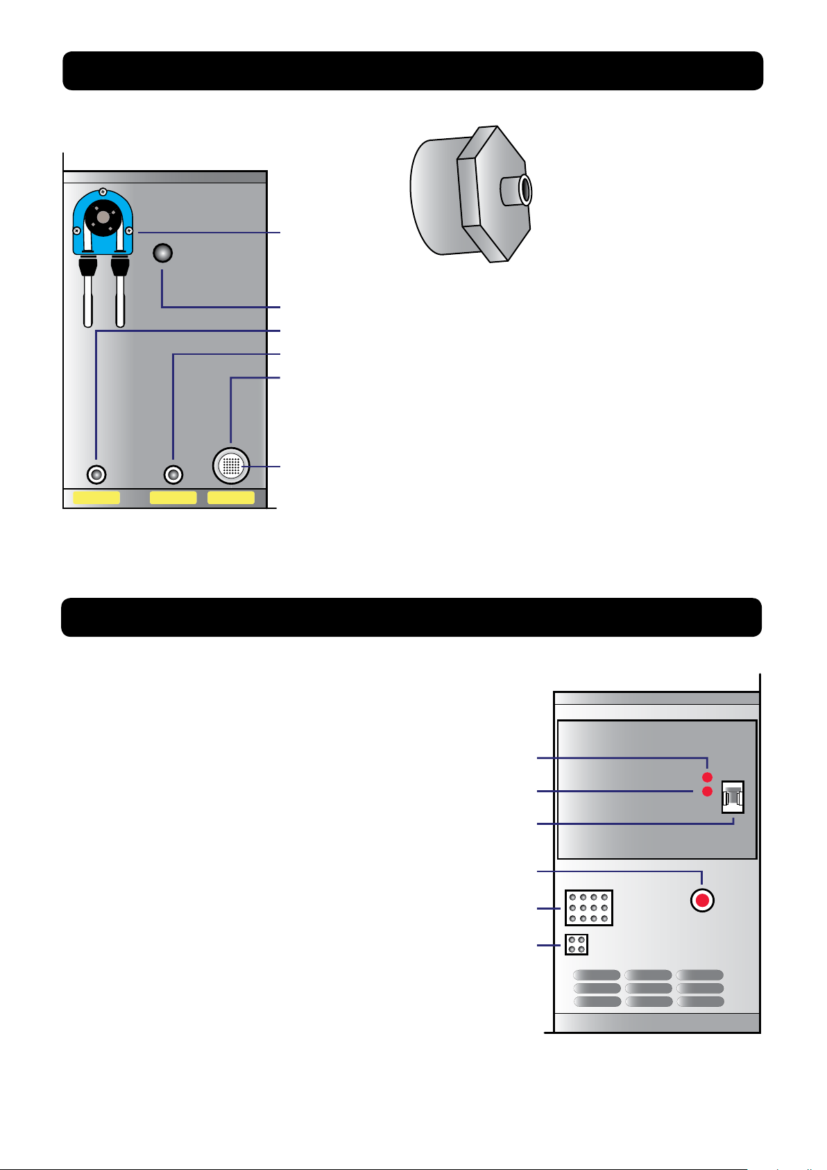
3.9
FUMOTIC® FRONT VEIW
Level probe sensitivity adjustment: This should not be touched
Level probe inverter: This should not be touched
Breaker switch: A safety measure to prevent overloading of the
circuit, can also be used to manually shut off the Fumotic®
Vapor discharge: manual discharge of vapor
12 Point connection: (12 pin twin model, 9 pin all other models)
4 point connection: Connector for tank level system
25
Rev 2, 18.06.19
Page 26

3.10
HOW TO CONNECT DIRECT WATERLINE TO FUMOTIC®
It is very imorprtant to note that there must be no more then 2.5 bar (35 psi) of pressure at any
time in the water line bieng connected to the Fumotic®
1. Push on ring around water
tube and pull hose.
WA
T
E
R
Connection
Point
4. From water tank, follow
level sensor wire until you
reach the wiring duct. Open
wiring duct and locate connection point.
2. Unscrew and remove
reducer.
5. Disconnect line and insert
the closed loop.
3. Connect using a standard
water hose connection
3/4”, do not over tighten
DANGER
Electrical Shock Hazard
Unplug/Disconnect power
before touching wiring of
any kind. Failure to do so
can result electric shock or
death.
6. Place wiring neatly back
in wiring duct
7. Turn on water supply, and
check for leaks.
8. Turn power back on to
unit.
3.11
SCALE FORMATION INSIDE FUMOTIC®
Scale build up is caused by the high mineral content in your water also know as “Hard
water”. Scale build up inside the Fumotic
®
will reduce performance and cause severe
damage. Should scale build up inside your Fumotic® contact your local Maturmeat® service
point for assistance, the process to remove scale from the system requires removal of the
Fumotic® and the use of solutions to dissolve the scale and uids to clean and purify the system
rendering it safe for use with food. Be advised that the manufacturers warranty is voided when
scale/calcium is found anywhere in the humidication system from the tanks leading into the
Fumotic® to inside of the Maturmeat® itself.
26
Rev 2, 18.06.19
Page 27

3.12
CLEANING MATURMEAT®
Cleaning Maintenance:
Cleaning your Maturmeat® should be done as often as needed or part of your HACCP program.
AISI 304 stainless steel has a layer of oxide preventing rust. Using abrasive and/or corrosive deter-
gents can deteriorate this layer. Follow the steps below for an efcent and thorough cleaning.
Before beginning, be sure to remove all food product and Maturmeat® accessories, such as
guides, grills/shelves, and hanging rods. Using a mild detergent, spray all internal surfaces including vent holes, corners, steam output valve, door/s and glass panel/s. Never spray Humidity
probe directly.
Current Recipe
AGED BEEF
TOTAL TIME
999 Hrs
TEMPERATURE
1.3˚C
SET
POINT
12:35 24/03/2018
1.0˚C
REMAING TIME
999 Hrs
SET
POINT
MATURING
TOTAL TIME
999
PHASE 1 OF 1
REMAING TIME
999
HUMIDITY
75%
81%
5.6
SET
POINT
PH
5.8
From the recipe screen, press the C.I.P.
Icon and conrm, this will start a 2 stage,
2 hour cleaning in place recipe that will
use Maturmeat® highest temperature,
and humidity settings to clean and nish off with a low humidity environment
designed to dry all internal surfaces.
Using paper towel, wipe down
all internal sufaces that may
have residual moisture. Thoroughly drying your Maturmeat®
will ensure its proper functionality and hygenic state.
Rev 2, 18.06.19
27
Page 28

CLEANING MATURMEAT® continued
Condensing Unit:
All condensing units require regular maintenance. The purpose of the condenser
is to release absorbed heat; If the condenser coils are clogged with dirt or the
ns are bent it restricts or block air ow
through the coils and interferes with the
heat exchange. This causes the system to
work harder and shortens the life of your
compressor. Please check your condensing unit regularly. Please unplug the unit’s
power or shut down power to the unit if
connected directly to an electrical panel
before attempting to clean. You can use
compressed air to clear away and loose
dirt or dust that may impair normal use.
NOTE
A general preventative maintenance schedule must be established to protect your Maturmeat®. A copy of the general preventative maintenance schedule (MOD_001 ENG) can be found
inside the unit along with this user manual. Based on tests performed at a factory level, It is highly
recommend that this maintenance occur at regular intervals once every 3 months, annually.
DANGER
Shock Hazzard
Before attempting to clean any part the unit, unplug the unit’s power or shut down power to
the unit if connected directly to an electrical panel, failure to do so can result in serious injury or
death.
3.13
EMPTYING THE DRAIN TRAY
DANGER
Slip Hazzard
Overow from the drain tray as a result
of neglecting to empty it can result in
serious injury or death.
Your Maturmeat® has a tray, which collects excess water moisture. The tray
should be emptied daily to avoid overowing onto your oor creating the possibility of unsafe or unsanitary conditions
in your workplace.
28
Rev 2, 18.06.19
Page 29

3.14
TEMPERATURE MAINTENANCE
You can cross referance the follow variable codes with the list found on pages 36 - 41
Heating and cooling is managed in the neutral zone on the basis of the temperature set point
and the temperature differentials (parameters DTNC and DTNF). Cooling is activated when
the set point +(DTF value) is exceeded and remains enabled until the set point is reached
(with DTNF = 0). Heating is activated when the temperature goes below the set point -(DTNC
value) and remains enabled until the set point is reached (with DTNC = 0). It is possible to
set a “dead zone” with the parameters (DTNC) and (DTNF) which de-activates heating and
cooling when the temperature is between the set point -(DTNC) and the set point +(DTNF).
ºC
(SetºC)+DTF
Cold On
(SetºC)+DTNF
(SetºC)
(SetºC)+DTNC
(SetºC)+DTC
Dehumidication
Activated
Humidication
Activated
The parameter (TSF) creates a delay between the cooling system’s switch off and it’s
subsequent re-activation. Heating can be deactivated with the parameter CA (CA = 0
disables the heating relay under all conditions).
Cold Off
Neutral Zone
Heat Off
Heat On
Time(s)
1
0
Time(s)
1
0
Time(s)
Rev 2, 18.06.19
29
Page 30

3.15
HUMIDITY MAINTENANCE
You can cross reference the follow variable codes with the list found on pages 36 - 41
Humidication and dehumidication is managed in the neutral zone on the basis of the humidity set point and the humidity differentials (parameters DUU and DUD). Dehumidication
is activated when the set point +(DUD value) is exceeded and remains enabled until the set
point is reached (with DUNS = 0). Humidication is activated when the humidity value falls
below the set point -(DUU value) and remains enabled until the set point is reached (with
DUNI = 0). It is possible to set a “dead zone” with parameters (DUNS) and (DUNI) which deactivates humidication and dehumidication when the humidity is between the set point
-(DUNI) and the set point +(DUNS). Humidication and dehumidication management can
be excluded with the variables (U) and (DE). With the (HR) variable you can decide whether
to show the humidity value on the display or not.
There are three dehumidication modes found in parameter (DEU):
0. Dehumidify with cooling (cooling is activated to dehumidify, heating is activated only to
maintain the ambient temperature;
1. Dehumidify with heating (heating is activated to dehumidify, cooling is activated only to
maintain the ambient temperature;
2. Separate dehumidication (the dehumidication system is activated without the use of
heating and cooling, they will only be activated in the event of thermoregulation).
It is possible to set a limit on the dehumidication phase with parameter (LDE) by agging an
alarm.
It is possible to set a limit on the humidication phase with parameter (LUM) by agging an
alarm.
(Set RH%)+DUD
(Set RH%)+DUNS
(Set RH%)
(Set RH%)+DUNI
(Set RH%)+DUU
Dehumidication
Activated
Humidication
Activated
RH%
Dehumidication On
Dehumidication Off
Neutral Zone
Humidication Off
Humidication On
Time(s)
1
0
Time(s)
1
0
Time(s)
30
Rev 2, 18.06.19
Page 31

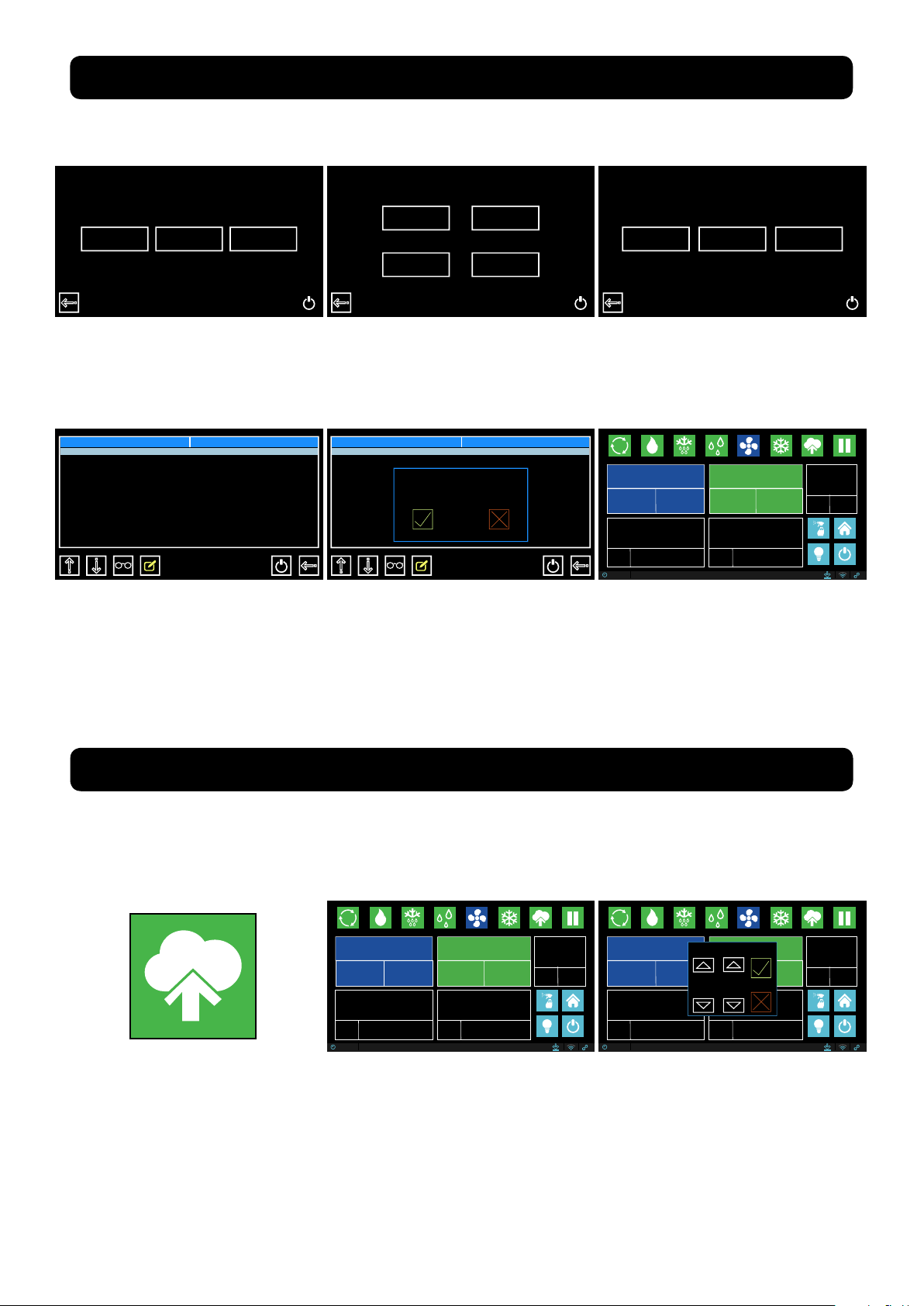
3.16
USB Drive Mode
Once finished, turn off power and disconnect the USB cable
®
FIRMWARE UPDATE Sicur Food Control®
Please follow these directions closely, failure to do can result in complete failure of the
device your trying to update, be sure to connect and disconnect cables when power is OFF, or unless otherwise directed. Alternatively, u s e t h e l i n k t o s e e t h e v i d e o o n l i n e
https://youtu.be/3aRbbZq-MOw
USB
Micro USB port
Micro USB
With your Maturmeat® powered down, connect your micro USB cable to the port on the
back side of the controller, and the USB to
your computer.
Welcome
24/03/2018 12:35
Once the 2 devices have been connected.
power up your Maturmeat®. Your controller
will now display the communication mode
screen, and a new window will open on your
computer. Copy/Cut the rmware le from
its current location and paste into newly
opened window. A small uploading window
will apear and will take several seconds
(depending on computer) to begin. Once
completed, power down your Maturmeat
and disconnect the micro USB cable from
the controller.
After powering back up, navigate to the
welcome screen. on the bottom lefthand
corner you will nd the updated rmware
version.
Serial
10002156, FW.1.15, PLC-A1.37, PLC-B1.37
Patent #1395586 - Climatouch
31
Rev 2, 18.06.19
Page 32

3.17
FIRMWARE UPDATE PLC’S
Please follow these directions closely, failure to do can result in complete failure of the device
your trying to update, be sure to connect and disconnect cables when power is OFF, or unless
otherwise directed.
Pins to connect bridge for communication mode
PLC A PLC B
Reset
Button
TTL connect
Step 1.
• With a computer connected to the internet, connect
the TTL Cable to install drivers.
• Open Flashloader.exe program or download form internet and install on your computer.
Reset
Button
Step 2.
• Before continuing stop any
running program on Maturmeat® and power down.
• With NO power to Maturmeat® connect the TTL cable to
the PLC.
TTL USB
Bridge
Step 3.
• Place the bridge on the 2
pins on the PLC to enable
communication made.
• After all connections
a r e m a d e p o w e r u p
Maturmeat®.
Step 4.
• Start Flashloader and begin
to congure the connection.
• Page 1 Select Com Port
Baud Rate: 115.200
Time Out (S): 5
Parity: Even
Echo: Disabled
32
Target is readable. Please click “Next” to proceed
Remove protection
Step 5.
• Page 2 The PLC will be
read quickly if successful the
Target Readable message will
appear in the window, if not
press the reset button on the
PLC just above the jumper.
Rev 2, 18.06.19
Please, select your device in the target list
Target
STM32_Connectivity-line_64K
STM32_Connectivity-line_128K
STM32_Connectivity-line_256K
Version
Step 6.
• Page 3 From the target drop
down box be sure to select
64K. Press Next.
Page 33

FIRMWARE UPDATE PLC’S continued
Please, select your device in the target list
Target
Version
STM32_Connectivity-line_64K
Download to device
C:\PLCStagionello124.hex
Customer Dealer Producer
****
1
2 3
4
5 6
7
8 9
0 C
.
Esc
OK
-
Target STM32_Connectivity-line_64K
Map file STM32_Connectivity-line_64K.STmap
Operation DOWNLOAD
File name C:\PLCStagionello124.hex
Step 7.
• Press Next
Step 10.
• Power down Maturmeat®
before removing cables.
• Make sure to disconnect the
bridge from both pins (Communication mode) and cover
1 pin only (Normal operation).
3.18
Mini Sim
Step 8.
• Page 4 Go to the “Download to device” section.
• Select the le to update ,
download the PLC rmware
Step 9.
• Page 5 the download will
start on its own, once complete “download successful”
will appear.
(ie. PLC Maturmeat 126.hex).
NOTE
Follow the same procedure to update the 2nd PLC. Once
both PLC’s have been updated, power up Maturmeat®.
Finally you can go back into the recipe and continue
production.
NETWORK CONNECTION
Connection to the Network
requires a Mini Sim (purchased separately in your
country) of at least 1 GB of
data only per month.
Once ready the Mini Sim can
be slid into its dedicated slot
on the back of the controller,
(with or without power).
With the Mini Sim in place, navigate to home screen, select
Dealer and enter code xxxx
(for code contact local Maturmeat® dealer).
Select Variables and scroll
down to APN. Press the pencil Icon and enter the code
provided by your service
provider. Press save/exit Icon.
Rev 2, 18.06.19
Current Recipe
AGED BEEF
TOTAL TIME
999 Hrs
TEMPERATURE
1.3˚C
SET
POINT
12:35 24/03/2018
REMAING TIME
999 Hrs
1.0˚C
TOTAL TIME
SET
POINT
999
PHASE 1 OF 1
MATURING
REMAING TIME
HUMIDITY
75
81%
999
%
5.6
SET
POINT
PH
5.8
Power down Maturmeat®, wait
5 seconds and power back up.
Once power returns to controller, you will be back on the
recipe screen. At the bottom
right hand corner, the link icon
should now be blue.
33
Page 34

3.19
TROUBLESHOOTING
Alarm
Code
E01
E02
E07
E08
Description
Ambient probe failureE00
Humidity probe failure
Evaporater probe failure (in this case any
defrost cycle will last for the time set in the
defrost variable)
Low freon level
High Freon pressure
Possible Cause/
Recommendations
· Check the ambient probe’s state
· If the problem persists, replace the
probe
· Check the humidity probe’s state and
connections
· Calibrate using a secondary Probe or
replace probe if neccessary
· Check power to evaporater probe
· If the problem persists, replace the
probe
· Check the amount of freon in system
· Check the condenser fan or the thermostatic expansion valve
· Make sure that the condenser is clean
E09
E10
E11
E12
Humidification time exceeded · Check the humidifier operation
Dehumidification time exceeded
Door Open
Condenser high temperature alarm
· Check the freon pressure
· Check for ice on the evaporator
· Check the door/s are closed
· Check the door switch
· Check the temperature on top of unit
· Check if the condenser fan is working
· Check if the condenser is clean
· Check power to the compressorThermal protection compressor failureE13
34
Rev 2, 18.06.19
Page 35

Alarm
Code
Description
Possible Cause/
Recommendations
Maximum or minimum humidity alarm
Fan two stopped · Check that varible AV2 is set to 0
E17
Fan one stopped
Air exchange failure
· Check that varible AV1 is set to 0
E16
E21
E23
E20
E22
E18
Low level H
2
0/Aroma
E15
No Power
· Refill tank with corresponding liquid
Minimum or maximum temperature alarm.
Condenser probe failure (If the probe is broken,
the condenser low temperature control for fan
shut-down is not taken into consideration)
· Check the state of the ambient probe
and calibrate using a secondary
certified probe
· Replace probe if neccessary
· Check power to the air exchange kit
· Check the humidity probe for correct
operation
· Calibrate using a secondary certified
probe or replace probe if neccessary
· Check the state of the compressor
· The probe does not read the temperature correctly or the compressor’s
stop/run command is not working.
· This alarm will only appear as a code
once power is restored
No Communication PLC AE14
·
·
· Check power to the compressorNo Communication PLC BE24
TROUBLESHOOTING continued
Rev 2, 18.06.19
35
Page 36

4.1
SYSTEM VARIABLES
Variable Description Value
HOT temperature dierential
DTC
DTF
DTNC
DTNF
DUU
This refers to the main SET-POINT. It is expressed in an
absolute value and denes the temperature hysteresis for
HOT with reference to the temperature SET POINT.
COLD temperature dierential
This refers to the main SET-POINT. It is expressed in an
absolute value and denes the temperature hysteresis for
COLD with reference to the temperature SET POINT.
Hot temperature NEUTRAL zone
This refers to the main SET-POINT. Heater is not enabled
in the neutral zone.
Cold temperature NEUTRAL zone
This refers to the main SET-POINT. Cooling is not enabled
in the neutral zone.
HUMIDIFICATION dierential
This refers to the humidity SET-POINT. It is expressed in an
absolute value and denes the humidication hysteresis
with reference to the humidity SET POINT.
Di. Minimum 0.2
Di. Maximum 10
Di. Minimum 0.2
Di. Maximum 10
Di. Minimum 0.0
Di. Maximum 3
Di. Minimum 0.0
Di. Maximum 3
Di. Minimum 1
Di. Maximum 10
Default
2.0 °C
2.0 °C
0.2
0
7%
DUD
DUNS
DUNI
DEHUMIDIFICATION dierential
This refers to the humidity SETPOINT. It is expressed in an
absolute value and denes the dehumidication
hysteresis with reference to the humidity SET POINT.
Upper humidity NEUTRAL zone
This refers to the main SET-POINT. Humidication is not
enabled in the neutral zone.
Lower humidity NEUTRAL zone
This refers to the main SET-POINT. Dehumidication is not
enabled in the neutral zone.
Di. Minimum 1
Di. Maximum 10
Di. Minimum 1
Di. Maximum 10
Di. Minimum 1
Di. Maximum 8
7%
1
1
36
Rev 2, 18.06.19
Page 37

Variable Description Value
Drainage duration (minutes)
At the end of the defrost cycle, cooling, dehumidication
and fan systems are stopped for the set SGO time.
Min 1 minute
Max 60 minutes
0 min.....20 min
0 DISABLED
DS
FAN PAUSE
After defrosting and after draining (if set in SGO ), the delay
countdown begins.
Interval set in hours between defrost periods.
Defrost temperature.
Defrosting is carried out until the temperature read by
the evaporator probe is achieved (if the probe fails to read
temp, the defrost is completed with the DS set time)
0h.....24h
0 DISABLED
-50°C.....+100°C
0 min.....20 min
0 DISABLED
IS
PV
SGO
TS
Maximum defrost duration (minutes).
Default
2h
20 min
10°C
5 min
0 min
ABT
Low temperature alarm
This allows a minimum ambient temperature value to be
dened. An alarm will be set o below the ABT
temperature; the alarm will appear onscreen, and an
audiable beep will sound the existence of the anomaly.
The alarm is triggered after the RAT time.
ABT <-50°C = OFF
ABT<AAT by 1.0
-4°C
High temperature alarm
This allows a maximum ambient temperature value to be
dened. An alarm will be set o above the ABT
temperature; the alarm will appear onscreen, and an
audiable beep will sound the existence of the anomaly.
The alarm is signalled after the RAT time. The alarm does
not interrupt any defrosts in progress.
Low humidity alarm
This allows a minimum humidity value to be dened for
the space to be humidied. The alarm is activated below
the ABU value, the alarm will appear onscreen, with an
audiable beep. The alarm is triggered after the RAU time.
AAT>200°C = OFF
AAT>ABT by 1.0
ABU<AAU by 1%
ABU< 1%=OFF
AAT
ABU
4°C
0%
HIGH humidity alarm
This allows a maximum humidity value to be dened for
the ambient to be humidied. The alarm is activated above
the AAU value, the alarm will appear onscreen, with an
audiable beep. The alarm is triggered after the RAU time.
AAU>ABU by 1%
AAU >99%=OFF
AAU
100%
SYSTEM VARIABLES continued
Rev 2, 18.06.19
37
Page 38

SYSTEM VARIABLES continued
Variable Description Value
VTE
VTC
M
AG
PVS
AVA
AVF
RAT
Evaporator probe temperature displayed
(temp will not be displayed if ESE = 0).
Condenser probe temperature displayed
(temp will not be displayed if ESC = 0).
Door switch input status (with door closed).
Aroma water input status.
Fan pause during defrosting.
Fan enablement during aroma.
Fan enablement during cooling.
Alarm notication time delay
for minimum or maximum temperature.
Temperature
Temperature
0=NO
1=NC
0=NO
1=NC
0=fans not operating
1=fans operating
0=DISABLED
1=ENABLED
0=DISABLED
1=ENABLED
0=INSTANTANEOUS
0<=OFF
0 min….240 min
Default
Read
Only
Read
Only
1
0
0
0
1
90 min
RAU
VMC
TSF
DEU
U
DE
Alarm notication time delay
for minimum or maximum humidity.
Fans in continuous operation.
If enabled during defrosting they stop if PVS=0.
Minimum time between cooling shut o and the next
subsequent switch on. It also stops the fans if they are not
enabled for other functions.
Dehumidication mode selection
Separated dehumidication enables hot and cold only for
temperature.
Enable Humidication.
Enable Dehumidication.
0=INSTANTANEOUS
0<=OFF
0 min….240 min
0=DISABLED
1=ENABLED
0 min…10 min
0 DISABLED
0=COOLING
1=HEATING
2=SEPARATE
DEHUMIDIFICATION
0=DISABLED
1=ENABLED
0=DISABLED
1=ENABLED
30 min
0
1 min
0
1
1
38
Rev 2, 18.06.19
Page 39

Variable Description Value
Humidity management. If disabled, the humidity is not
shown on the display.
-20%.....0.....+20%
0=DISABLED
1=ENABLED
CSU
Exclude evaporator probe.
Ambient probe value correction.
Condenser probe value correction.
-20°C.....0.....+20°C
-20°C.....0.....+20°C
0=DISABLED
1=ENABLED
CSA
ESE
HR
CSC
Humidity probe value correction.
Default
To be
calibrated
To be
calibrated
To be
calibrated
1
1
ESC
Exclude condenser probe.
0=DISABLED
1=ENABLED
1
Defrost type, cycle inversion (with hot gas), resistance or
static. The cold output is also enabled with hot gas. Static
defrost will still reach the temperature the end of the
defrost cycle.
Minimum value that can be attributed to the temperature
set point.
1=HOT GAS
0=RESISTANCE
2=STATIC
-50°C.....+200°C
LST < HST by 1°C
SBR
LST
1
-3°C
Enable Heat.
0=DISABLED
1=ENABLED
CA
1
Maximum value that can be attributed to the temperature
set point.
-50°C.....+200°C
HST>LST by 1 °C
HST
35°C
DBF
Temperature dierential with reference to the set point
for COLD BLOCK. This constitutes the SET -DBF limit
below which the cooling start relay and the
Dehumidication relay are disabled.
0°C.....+40°C
0°C
DBC
Temperature dierential with reference to the set point
for HOT BLOCK. This constitutes the SET +DBF limit above
which the heating start relay and the Humidication relay
are disabled.
0°C.....+40°C
0°C
RATC
Alarm time delay for maximum condenser temperature.
0<= OFF
0=INSTANTANEOUS
0 min.....240 min
1 min
DEHUMIDIFICATION time limit. If dehumidication fails to
reach the humidity SET POINT within the LDE time, an
alarm will be triggered.
0 min.....240 min
0=DISABLED
LDE
0
SYSTEM VARIABLES continued
Rev 2, 18.06.19
39
Page 40

SYSTEM VARIABLES continued
Variable Description Value
VU
BVC
DVC
RAP
AMTC
DMTC
FC
Fan enablement during humidification. This function is
directly related to the humidifier.
Condenser fan stop. If the BVC is higher than the
condenser probe reading, the fan stops. This function also
takes into consideration hot gas defrosting.
Allows condenser fan to restart after this many degree
points.
Door/s open alarm delay. A value below 0, disables the
alarm. A value of 0 creates an instant alarm. Once alarm is
triggered all functionality is stopped except alarm and
internal light.
Condenser maximum temperature alarm. AMTC is not
blocked by BVC if there is an overlap.
Condenser max temp alarm must drop this many degree
points before alarm does not reappear onscreen.
Duration of cooling cycle enablement. If the ambient
probe fails, it works for a total FC minutes. The FC
countdown starts at the end of the PFC time.
0=DISABLED
1=ENABLED
0°C.....130°C
BVC<0°C = OFF
1°C.....30°C
0 min.....120 min
0°C.....130°C
>130°C OFF
1°C.....30°C
0 min.....120 min
0=DISABLED
Default
1
10
°C
5°C
1 min
48°C
10°C
15 min
PFC
LR
PF
LUM
VC
TF
LO
ESPH
Pause cooling cycle. This variable is only considered by
FC time.
Coolant level inlet status.
Freon high pressure inlet status.
Humidification time limit. If humidification fails to reach
the humidity SET POINT within the LUM time, an alarm
will be triggered.
Enable hot ventilation only.
Cold thermal inlet status.
Air change inlet status.
Exclude PH probe.
0 min.....120 min
0=DISABLED
0=NO
1=NC
0=NO
1=NC
0 min.....120 min
0=DISABLED
0=DISABLED
1=ENABLED
0=NO
1=NC
0=NO
1=NC
0=DISABLED
1=ENABLED
5 min
0
0
0
1
0
0
1
40
Rev 2, 18.06.19
Page 41

Variable Description Value
Stand-by inlet status.
0=NO
1=NC
0=NO
1=NC
DU
Fan 1 malfunction alarm.
If enabled, this function allows me to send an alarm when
fan 1 stops or if sensor 1 is disconnected.
PH probe correction.
Disable cold + dehumidification inlet status.
-5.00.....0.00.....+5.00
0=N0
1=NC
0=DISABLED
1=ENABLED
CSPH
AV1
SDY
DFD
Disable humidity inlet status.
Default
0
0
0
0
0
AV2
Fan 2 malfunction alarm.
If enabled, this function allows me to send an alarm when
fan 2 stops or if sensor 2 is disconnected.
0=DISABLED
1=ENABLED
0
Enable fans in dehumidification only.
Block defrost temperature reading.
0=DISABLED
1=ENABLED
0=DISABLED
1=ENABLED
VDE
BTUS
0
0
Disable hot+humidifier+smoke inlet status.
0=N0
1=NC
DCUF
0
Block softening temperature reading.
0=DISABLED
1=ENABLED
BTUR
0
BTUA
Block air change temperature reading.
0=DISABLED
1=ENABLED
0
HACF
HACCP data storage frequency.
0.....240 min
240
PSWD
Dealer Password.
Default
0
Manufacturer Password.
Default
PSWP
1234
Positive pH differential.
0.....14
DPHP
14
Negative pH differential.
DPHN
0.....14
14
FAHR
Change temp value to display in fahrenhiet.
0=DISABLED
1=ENABLED
0
EPSU
Screen lock enable/disable.
0=DISABLED
1=ENABLED
Screen lock Password.
Default
PSWU
****
****
SYSTEM VARIABLES continued
Rev 2, 18.06.19
41
Page 42

SYSTEM VARIABLES continued
Variable Description Value
APN
APNU
APNP
SVUS
SVPW
SVIP
SVPT
LSPH
LIPH
APN GPRS.
APN username.
APN password.
Server username.
Server password.
Server address.
Server port.
pH upper limit.
pH lower limit.
provided by ISP
leave empty
leave empty
0.....14
0.....14
Default
To be added
xf
password
156.54.169.93
80
7
4
RAPH
AAPH
ALWO
pH alarm delay.
pH alarm on/o.
Always on.
0=INSTANTANEOUS
0 min....240 min
0=DISABLED
1=ENABLED
0=DISABLED
1=ENABLED
50 min
1
0
42
Rev 2, 18.06.19
Page 43

4.2
-3°C+35°C
MATURMEAT® SPECIFICATIONS
The Maturmeat® line is entirely built in AISI 304 stainless steel CE certied to be used in contact
with a food. The technical specications and models are described in the table below:
Model Size
MATC150TF
MATC060TF
MATC100TF
MATC200TF
MATCTWITF
STGTWCOMB
90 X 78 X 211
110 X 78 X 132
73 X 78 X 211
140 X 78 X 211
140 X 78 X 211
140 X 78 X 211
4.3
148
88
Temp Range Voltage
-3°C+35°C
-3°C+35°C
-3°C+35°C
-3°C+35°C
-3°C+35°C
+2°C+35°C
230 +/-10%
230 +/-10%
230 +/-10%
230 +/-10%
230 +/-10%
230 +/-10%
Hz
50/60
50/60
50/60
50/60
50/60
50/60
Sicur Food Control® SPECIFICATIONS
210
156
Current Recipe
AGED BEEF
TOTAL TIME
999 Hrs
TEMPERATURE
1.3˚C
SET
POINT
12:35 24/03/2018
1.0˚C
REMAING TIME
999 Hrs
TOTAL TIME
SET
POINT
999
PHASE 1 OF 1
MATURING
REMAING TIME
HUMIDITY
75%
81%
999
5.6
SET
POINT
PH
5.8
Kw Amp Noise Kg Door
3.99
2.80
2.37
4.14
4.14
4.09
17.3
11
10.8
18
18
17.8
<72
<72
<72
<72
<72
<72
200
150
140
250
252
253
1
2
1
2
2
2
148
210
Back Side
Rev 2, 18.06.19
Connection (Printer)
Dip Switches
Micro USB (Firmware
update)
Power Supply
RJ10 to PLC A
Mini Sim slot (GSM)
Antenna connection
43
Page 44

®
Sicur Food Control
Power supply
Voltage 230 V~ ± 10% 50Hz/60Hz
Max. absorbed power (electronic control only) 10 V A
Climatic conditions
Working temperature - 5.....+50°C
Storage temperature -10.....+70°C
Ambient relative humidity Less than 90% RH
General Characteristics
Type of connectable probes (temperature) NTC 10K 1%
Resolution (ambient temperature) 0.1° C
Probe reading precision (ambient temperature) ± 0.1°C
Reading range -50.....+200°C
Humidity probe 0-100% 4-20 mA
Humidity probe reading
Humidity probe reading range 0-99% RH
Outlet characteristics
Description Installed relay Card outlet characteristics Notes
precision see characteristics of humidity probe
SPECIFICATIONS conituned
Cold (outlet 16-17) (30 A-C1 Relay) 30A 240V - (AC3) (2HP) (100K cycles)
7 outlets from 18 to 29
6 outlets from 18 to 29
Dimension characteristics
dimensions
Climatouch® dimensions
4.4
FUNCTIONS MANAGED BY Sicur Food Control
(16 A-C1 Relay) 16A 250V - (AC1) (4KW) (10M cycles)
180 x 50 x 130 mmMASTER
118 x 30 x 89 mm
®
All the outlets are
clean unpowered
contacts.
- Display and regulation of set temperature, set humidity (neutral zone) and set PH (read only)
parameters.
- Enable/disable stand-by status
- Probe alarm warnings
- Regulation of air cycle control parameters
- Regulation of defrosting parameters
- Regulation of rest period parameters
- Regulation of fan parameters
- Regulation of air exchange kit (Standard on models 150kg, 400kg, 800kg, 300kg and 600kg.
Optional on models 60kg, 100kg, 200kg twin 100+100kg and Combo)
- Regulation and management of control parameters for the smoking/avouring and/or humidication stages
- Display of the outlet status
- Simultaneous display of temperature, humidity and pH values
- Display and management of both, default climatic recipes and saved recipes created by you,
with automatic variation of the times set for the individual stages and for temperature, humidity,
smoking/avoring, fan speed, rest periods and air cycle periods.
- Clock and date function
44
Rev 2, 18.06.19
Page 45

4.5
PLC A SPECIFICATIONS
1 2 3 4
33 3245 44 43 42 41 40 39 38 37 36 35 34
31 30 29 28 27 26 25 24 23 22 21 20
PLC (Programmable Logic Controller)
A
Communication Connections
5 6 7 8 9 10
pH Probe
Connection
2 Pin 3 Pin
To
Controller
To
PLC B
Power Supply Section
1 & 2: Power supply 24 V/AC/DC 50/60 Hz
Digital Input Section
3 & 9: Humidity probe 4.20 mA (0-100 Rh%)
7 & 8: Evaporator probe
5 & 6: Ambient probe
44 & 45: Stand-by forcing
40 & 45: Door Switch
43 & 45: Force hot disable
42 & 34: Force cold disable
41 & 45: Force humidication disable
RJ10 Connection: RJ10 to RJ10 com cable to controller
2 Pin: Cover both pins for com mode during rmware update
3 Pin: DWL to USB cable for use during rmware update
Digital Output Section
32 & 33: Compressor
20 & 21: Heating
22 & 23: Flavouring
24 & 25: Humidication
26 & 27: Dehumidication
28 & 29: Rest Cycle
30 & 31: Alarm
RJ10 Connection: RJ10 to RJ10 com cable to PLC B
Rev 2, 18.06.19
45
Page 46

4.6
PLC B SPECIFICATIONS
45 44 43 42 41 40 39 38 37 36 35 34
PLC (Programmable Logic Controller)
Communication Connections
1 2 3 4
5 6 7 8 9 10
2 Pin 3 Pin
31 30 29 28 27 26 25 24 23 22 21 20
B
To
PLC A
Power Supply Section
1 & 2: Power supply 24 V/AC/DC 50/60 Hz
Digital Input Section
5 & 6: NTC condenser probe
44 & 45: Low H20/avouring level alarm
43 & 45: Low Refrigerant level alarm
42 & 45: High Freon pressure alarm
41 & 45: Compressor thermal alarm
40 & 45: Air exchange alarm
RJ10 Connection: RJ10 to RJ10 com cable to PLC A
2 Pin: Cover both pins for com mode during rmware update
3 Pin: DWL to USB cable for use during rmware update
Digital Output Section
20 & 21: Defrost
22 & 23: Low ventilation
24 & 25: High ventilation
26 & 27: Air exchange
28 & 29: Light
30 & 31: Condenser fan
46
Rev 2, 18.06.19
Page 47

L
N
32A
20A 22B
20B 24B
26B
28B
Fumotic®
230V
Digital
power
supply
230V
24V
1A
1B
1Display
C
1
Heat Element
Door Frame
33A
Compressor
C
1
Heat Element
Fans
21A
21B
Solenoide
Defrost
Heat Element
Evaporator Tray
Heat Element
Drain
25B
Barrel
Fan
27B
LED
Light
29B
Condenser Fan
31B
N Fumotic®
Ambient Probe
Evaporator Probe
Door Switch
+
-
Humidity Probe
5B6B5A6A7A8A45A
40A
3A
9A
2A
2B
2 Display
Safety Thermostat
Heat Element
Fans
Safety
Thermostat
Electrical Schematic
60kg / 100kg Model
Red
Red
Red
White
White
White
2
Solenoide
23B
230V
Male 2pin
H
2
0 Level
Female 2pin
Male 2pin
Aroma Level
Liquid Level Sensor
Liquid Level Sensor
Male 4pin
Aroma Level
Female 2pin
H
2
0 Level
Condensor Probe
liguori S.
Ufficio tecnico
Cliente
22-07-2013
Centro
Elaborazione Dati
Arredo Inox S.r.l.
Zona Industriale Località Zigari
88900 - Crotone
P.I. 02729540795
liguori Salvatore
Revisione
17-06-2019
Data
yB d
e
ngiseDal
acS
30B
Fan Air
Exchange
Drain
Fumotic®
2
0
2
High
Low
1
Digital
power
supply
230V
12V
2
9
3
Common Fumotic®
Alarm Fumotic®
45B
Alarm Fumotic®
44B
25A
Humidity Fumotic®
22A
24A
23A
Aroma Fumotic®
6
Ground Fumotic®
1
547
8
Male 9pin
2
9
3
65
7 8
1
4
1
3
2
1
2
1
2
1
2
1
2
4.7
ELECTRICAL SCHEMATIC 100kg
Rev 2, 18.06.19
47
Page 48

L
N
Fumotic®
230V
Heat Element
Door Frame
33A
Heat Element
Fans (L)
21A
21B
Solenoid
Defrost
Heat Element
Evaporator Tray (R)
Heat Element
Drain (R)
Heat Element
Drain (L)
27B
Condenser
Fan
31B
N Fumotic®
2A
2B
2Display
Safety Thermostat
Heat Element Fans (L)
Safety Thermostat
Heat Element Fans (R)
Heat Element
Fans (R)
Heat Element
Evaporator Tray (L)
Fan Air
Exchange
Red
Red
Red
White
White
White
Compressor
230V
liguori S.
Ufficio tecnico
Cliente
22-07-2013
Centro
Elaborazione Dati
Arredo Inox S.r.l.
Zona Industriale Località Zigari
88900 - Crotone
P.I. 02729540795
liguori Salvatore
Revisione
17-06-2019
Data
Scala
Designed By
32A
20A
20B 24B
22B 26B
28B
30B
1A
1B
1Display
Electrical Schematic
150kg Model
Ambient Probe
Evaporator Probe
Door Switch
+
-
Humidity Probe
5B6B5A6A7A8A45A
40A
3A
9A
Condensor Probe
Solenoide
Drain
Fumotic®
Digital
power
supply
230V
24V
C
1
Safety
Thermostat
2
C
1
2
C
1
2
25B
Barrel
Fan (L)
23B
0
2
High
Low
1
25B
Barrel
Fan (R)
23B
0
2
High
Low
1
LED
Light
29B
Digital
power
supply
230V
12V
Common Fumotic®
Alarm Fumotic®
45B
Alarm Fumotic®
44B
25A
Humidity Fumotic®
22A
24A
23A
Aroma Fumotic®
6
Earth Fumotic®
1
547
8
2
9
3
Male 9pin
2
9
3
65
7 8
1
4
Male 2pin
H
2
0 Level
Female 2pin
Male 2pin
Aroma Level
Liquid Level Sensor
Liquid Level Sensor
Male 4pin
Aroma Level
Female 2pin
H
2
0 Level
1
3
2
1
2
1
2
1
2
1
2
4.8
ELECTRICAL SCHEMATIC 150kg
48
Rev 2, 18.06.19
Page 49

L
N
33A
21B
Heat Element Drain (R)
27B
Condenser
Fan
31B
N Fumotic®
Heat Element Drain (L)
Compressor
Solenoide
230V
liguori S.
Ufficio tecnico
Cliente
22-07-2013
Centro
Elaborazione Dati
Arredo Inox S.r.l.
Zona Industriale Località Zigari
88900 - Crotone
P.I. 02729540795
liguori Salvatore
Revisione
Data
Scala
Designed By
17-06-2019
Common Fumotic®
Ambient Probe
Evaporator Probe
Door Switch
+
-
Humidity Probe
5B6B5A6A7A8A45A
40A
3A
9A
Alarm Fumotic®
45B
Alarm Fumotic®
44B
25A
Humidity Fumotic®
22A
24A
23A
Aroma Fumotic®
Condensor Probe
Electrical Schematic
200kg Model
Solenoid
Defrost
Fan Air
Exchange
Heat Element
Evaporator Tray (L)
Heat Element
Evaporator Tray (R)
Heat Element
Door (R)
Heat Element
Door (L)
Fumotic®
230V
32A
20A
20B 24B
22B 26B
28B
30B
2A
2B
2Display
Red
Red
Red
White
White
White
1A
1B
1Display
Drain
Fumotic®
Digital
power
supply
230V
24V
C
1
Safety
Thermostat
2
Heat Element
Fans (L)
21A
Safety Thermostat
Heat Element Fans (L)
Safety Thermostat
Heat Element Fans (R)
Heat Element
Fans (R)
C
1
2
C
1
2
25B
Barrel
Fan (L)
23B
0
2
High
Low
1
25B
Barrel
Fan (R)
23B
0
2
High
Low
1
LED
Light
29B
Digital
power
supply
230V
12V
2
9
3
6
Earth Fumotic®
1
547
8
Male 9pin
2
9
3
65
7 8
1
4
Male 2pin
H
2
0 Level
Female 2pin
Male 2pin
Aroma Level
Liquid Level Sensor
Liquid Level Sensor
Male 4pin
Aroma Level
Female 2pin
H
2
0 Level
1
3
2
1
2
1
2
1
2
1
2
4.9
ELECTRICAL SCHEMATIC 200kg
Rev 2, 18.06.19
49
Page 50

L
N
Fumotic®
230V
Heat Element
Door Frame (R)
33A (L)
Compressor (L)
Heat Element Fans (L)
21A (L)
Condenser Fan (R)
31B (R)
N Fumotic®
Safety Thermostat
Heat ElementFans (L)
Safety
Thermostat
(R)
32A
20A
24B
22B 26B
Heat Element
Door Frame (L)
Safety
Thermostat
(L)
(L)
(R)
21B (L)
Heat Element
Evaporator Tray (L)
Solenoide
Defrost (L)
Heat Element
Drain (L)
Heat Element Fans (R)
21A (R)
Safety Thermostat
Heat Element Fans (R)
33A (R)
Compressor (R)
1Display (L) 1A (R) 1B (R)
Fan Air
Exchange (R)
Condenser Fan (L)
31B (L)
Solenoide (R)
230V
Solenoide (L)
liguori S.
Ufficio tecnico
Cliente
22-07-2013
Centro
Elaborazione Dati
Arredo Inox S.r.l.
Zona Industriale Località Zigari
88900 - Crotone
P.I. 02729540795
liguori Salvatore
Revisione
Data
Scala
Designed By
17-06-2019
1Display (R)1A (L) 1B (L)
2Display (L) 2A (R) 2B (R) 2Display (R)2A (L) 2B (L)
20B 28B
30B
32A
20A 22B
24B
26B
20B 28B
30B
Heat Element
Evaporator Tray (R)
21B (R)
Heat Element
Drain (R)
Solenoide
Defrost (R)
Fan Air
Exchange (L)
Electrical Schematic Table1
Twin 100+100kg Model
Drain Fumotic®
C
1
2
C
1
2
C
1
2
C
1
2
Digital
power
supply
230V
24V
27B (L)
27B (R)
25B (R)
Barrel
Fan (R)
23B (R)
0
2
High
Low
1
25B (L)
Barrel
Fan (L)
23B (L)
0
2
High
Low
1
LED
Light
29B (L)
Digital
power
supply
230V
12V
LED
Light
29B (R)
Digital
power
supply
230V
12V
2
12
3
4.10
ELECTRICAL SCHEMATIC TWIN 100+100kg TABLE 1
50
Rev 2, 18.06.19
Page 51

Common
Fumotic®
Condensor Probe (L)
Ambient Probe (L)
Evaporator Probe (L)
Door Switch (L)
Humidity Probe (L)
5B (L)
6B (L)
5A (L)
6A (L)
7A (L)
8A (L)
45A (L)
40A (L)
3A (L)
9A (L)
22A (L)
24A (L)
Condensor Probe (R)
Ambient Probe (R)
Evaporator Probe (R)
Door Switch (R)
+
-
Humidity Probe (R)
Humidity 2
Fumotic®
Aroma 2
Fumotic®
22A (R)
24A (R)
48B (L)
liguori S.
Ufficio tecnico
Cliente
22-07-2013
Centro
Elaborazione Dati
Arredo Inox S.r.l.
Zona Industriale Località Zigari
88900 - Crotone
P.I. 02729540795
liguori Salvatore
Revisione
Data
Scala
Designed By
17-06-2019
+
-
5B (R)
5A (R)
7A (R)
45A (R)
3A (R)
6B (R)
6A (R)
8A (R)
40A (R)
9A (R)
Electrical Schematic Table2
Twin 100+100kg Model
Aroma 1
Fumotic®
23A (R)
6
Humidity 1
Fumotic®
25A (R)
5
23A (L)825A (L)
7
4
Alarm 1
Fumotic®
45B (R)
10
Alarm 1
Fumotic®
44B (R)
9
Alarm 2
Fumotic®
45B (L)
11
Ground
Fumotic®
1
Female 2pin
Male 4pin
Aroma Level
Female 2pin
H
2
0 Level
1
3 4
2
1
2
1
2
Liquid Level Sensor
Male 2pin
Aroma Level
1
2
Male 2pin
H
2
0 Level
Liquid Level Sensor
1
2
Male 12pin
321
654
121110
987
4.11
ELECTRICAL SCHEMATIC TWIN 100+100kg TABLE 2
Rev 2, 18.06.19
51
Page 52

21
11
A1
22
24
12
14
A2
21
11
A1
22
24
12
14
A2
21
11
A1
22
24
12
14
A2
21
11
A1
22
24
12
14
A2
K1
K2
Aroma Pump
K3
Single Output Fumotic® 60/100/150/200
K4
Female 4pin
H20 Level
Aroma Level
Ufficio tecnico
Centro
Elaborazione Dati
Arredo Inox S.r.l.
Zona Industriale Località Zigari
88900 - Crotone
P.I. 02729540795
Liguori Salvatore
Revisione
18-06-2019
N4L2
L
L
N
N
1
2
4
Solenoid Vapor
Manual Release
4
2
Pressure
Switch
1
Solenoid Vapor
N
Fumotic
Bivalente 1 via
L
N
Common
Alarm
Alarm
Aroma
Female 9pin
Drain
Humidity
3412
2
936 5
7814
G
Pump Thermostat
Water Pump
Solenoid
Water
Intake
141211A2A1
MinMaxCom
Boiler Heat
Element
Thermofuse
Thermofuse
Level Relay
Water
Level
Probe
G
Curcuit
Breaker
Electro
Magnetic
Filter
U1 U3
G
4.12
ELECTRICAL SCHEMATIC FUMOTIC® 60/100/150/200KG
52
Rev 2, 18.06.19
Page 53

Ufficio tecnico
Centro
Elaborazione Dati
Arredo Inox S.r.l.
Zona Industriale Località Zigari
88900 - Crotone
P.I. 02729540795
Liguori Salvatore
Revisione
18-06-2019
21
11
22
24
12
14
K1
K6
K7
Electro
Magnetic
Filter
U1
U3
N4
L2
1
2
4
Solenoid Vapor
Manual Release 1
1
2
4
Solenoid Vapor
Manual Release 2
Aroma Pump 1
Aroma Pump 2
141211A2A1
MinMaxCom
Boiler Heat
Element
Thermofuse
Solenoid Vapor 1 Solenoid Vapor 2
4
2
1
Pressure Switch
Pump Thermostat
Water Pump
Aroma 1
Common
Ground
Drain
Humidity 2
Aroma 2
Alarm 2
Alarm 1
Alarm 1
Solenoid
Water
Intake
Double Output Fumotic®
Thermofuse
Curcuit
Breaker
L
N
N
N
L.
L
Female 4pin
34
12
Alarm 2 L.
A1
A2
21
11
22
24
12
14
A1
A2
21
11
22
24
12
14
A1
A2
21
11
22
24
12
14
A1
A2
21
11
22
24
12
14
A1
A2
21
11
22
24
12
14
A1
A2
21
11
22
24
12
14
A1
A2
Fumotic
Bivalente 2 vie
Female
12pin
K2 K3 K4 K5
Level Relay
Water
Level
Probe
Humidity 1
3 2 1
6 5 4
12 11 10
9 8 7
H
2
0 Level
Aroma Level
Twin/Combo
G
G
4.13
ELECTRICAL SCHEMATIC FUMOTIC® TWIN 100+100KG
Rev 2, 18.06.19
53
Page 54

5.1
Arredo Inox Srl is the exclusive licensed manufacturer of the patents from Alessandro Cuomo Brevetti Milano
This limited warranty covers all standard plug-in cabinets and walk-in units up to 800kg maximum load. Arredo Inox Srl
warranties its equipment to the original purchaser against defects in materials or workmanship for a period of one year
from the date of installation. This limited warranty is not transferable. Warranties for parts and labor last one year, If service
work is carried out under Limited Warranty, this will not extend the Limited Warranty period for the unit, or for the new
parts. The warranty is voided by improper placement/storage, use, or when used in ambient temperatures exceeding
32oC / 89oF, please refer to user/instructional manual for further details. The warranty period begins on the date of instal-
lation, after validating the warranty by sending an e-mail to the following address ufcioqualita@stagionellostore.com
enclosing the installation worksheet, and applies only if the purchaser has not violated any of the exclusions or limitations
listed below.
What is not covered under this Limited Warranty
• Normal wear and tear;
• Deliberate or negligent damage, damage caused by failure to observe operating instructions, incorrect installation
or by connection to the wrong voltage, damage caused by chemical or electro-chemical reaction, rust, corrosion or
water damage including but not limited to damage caused by excessive minerals in the water supply, damage caused
by abnormal environmental conditions;
• Consumable parts, these include, but are not limited to: light bulbs, bulb enclosures, batteries, fuses, and gaskets;
• Non-functional and decorative parts, which do not affect normal use of the appliance, including any scratches and
possible color differences;
• Any build up of scale/calcium a) in and/or around the lines leading into or exiting the Fumotic®, b) within the
Fumotic® itself;
• Accidental damage caused by foreign objects or substances and cleaning or unblocking of lters, drainage systems;
• Charges for service calls resulting in a diagnosis of equipment that was properly operating including, but not limited
to: diagnosing equipment operation in a defrost mode, rest/recovery period, air cycling period, air exchange period, or
power to the equipment was disconnected or interrupted, or that was shut down by over current or high/low pressure
controls, or that the indicating temperature or humidity device was incorrectly calibrated;
• Failures caused by a) alteration/modications or parts installed but not authorized by manufacturer, b) abuse and/
or misuse of equipment, c) failure to provide adequate air ow around condenser and/or evaporator air coils, and/or
d) failures caused by environmental effects and/or outside inuences, including but not limited to re damage, smoke
damage, or explosions;
• Cleaning debris or removing ice from a heat transfer surface, not caused by a defect in materials and workmanship;
• The replacement of refrigerant without evidence of a leak in the system components;
• Adjustments of any operation control such as the thermostatic expansion valve, defrost components, pressure, oil
safety, or temperature thermostat/controller;
• Repairs not carried out by our appointed service providers and/or an authorized service contractual partner or where
non-original parts have been used;
• Repairs caused by installation, which is faulty or not according to specication;
• Transportation damages of any kind;
• Cost for carrying out the initial installation of the unit;
LIMITED WARRANTY
Due to the fact that Maturmeat® uses programs that are modiable by it’s operator, Arredo Inox srl accepts no
responsibility for product loss, spoilage, unsafe/unhealthy or unsanitary products produced in the Maturmeat®. Please
carefully read the instructional manual before attempting to install your unit to avoid injury and to ensure proper
installation. Thoroughly inspect your unit after unpacking and report any damage during transit to your local area dealer,
distributor, reseller, agent, etc. and transport company. All warranty claims must be made to the local area dealer, distributor, reseller, agent, etc. In the case where the unit is purchased directly from the manufacturer all warranty claims
must be made to ufcioqualita@stagionellostore.com. Any repair or replacement of a covered component may be
made with a functionally equivalent component, as determined by Arredo Inox Srl.
Installed in the electronic control settings, default recipes and climatic variables of operation are to be considered
indicative and otherwise be changed and / or user programmable in case of damage and / or failure of the food
content in the machine as a result of execution the same, the manufacturer cannot be held responsible, civil and / or
criminal and may not be charged at the same in anyway.
Humidity and Temperature Sensors/ Probes:
The probes in each Maturmeat® used should calibrated with a certied instrument and by trained personnel, all probes
installed on the machines are very sensitive, it is recommended that they be calibrated each time a new production
lot is started. Each unit is thoroughly tested before shipment, any inaccuracies or operating problems before and after
the installation must be reported to the manufacturer within the rst 8 days to ensure proper function, the manufacturer
cannot be held liable in such case.
pH Probe Storage:
The probes should be stored in a protective capsule or in a container with their membranes immersed in a
3M KCI solution. The storage temperature should be between 10°/30°C, and never below -5°C. In case of loss of the
protective capsule during transport or storage, the KCI could be removed easily by rinsing the probe in water. The probe
will not suffer any consequences from this loss. The electrode must always be kept in its storage capsule lled with the
corresponding electrolytic solution. The sensitive membrane should never be dry. If you do not have electrolyte solution,
you can submerge the electrode in pH 4 buffer solution. Never store the electrode in distilled water.
54
Rev 2, 18.06.19
Page 55

5.1
PROPER DISPOSAL
User’s Information
Under Directives 2002/95/EC, Directive 2002/96/EC of the European
Parliament and of the Council on the restriction of the use of certain
hazardous substances in electrical and electronic equipment and
DIRECTIVE 2003/108/EC amending Directive 2002/96/EC on waste
electrical and electronic equipment.
Correct Disposal of This Product (Waste Electrical & Electronic Equipment)
(Applicable in the European Union and other European countries with separate collection
systems) This marking on the product, accessories or literature indicates that the product
and its electronic accessories (e.g. charger, headset, USB cable) should not be disposed
of with other household waste at the end of their working life. To prevent possible harm
to the environment or human health from uncontrolled waste disposal, please separate
these items from other types of waste and recycle them responsibly to promote the sustainable reuse of material resources. Household users should contact either the retailer where
they purchased this product, or their local government ofce, for details of where and
how they can take these items for environmentally safe recycling. Business users should
contact their supplier and check the terms and conditions of the purchase contract. This
product and its electronic accessories should not be mixed with other commercial wastes
for disposal.
If outside of Europe, please refer to the Laws and bylaws specic to
your Country, State, Province, Region, County, Municipality, etc., on
how to properly dispose of this unit.
Rev 2, 18.06.19
55
Page 56

WWW.ARREDOINOX.IT
Via F. Mancuso 18, Zona Industriale
88900 - Crotone (KR) Italy
Tel. +39 0962/931654
Fax +39 0962/931685
info@arredoinox.it
56
Rev 2, 18.06.19
Page 57

Via F. Mancuso 18, Zona Industriale
88900 - Crotone (KR) Italy
Tel. +39 0962/931654
Fax +39 0962/931685
info@arredoinox.it
www.arredoinox.it
WWW.ARREDOINOX.IT
57
Rev 2, 18.06.19
 Loading...