

Page 1
Back Bar Bottle Coolers
Models BD-CN-0007-HC, BB-CN-0012-DH, BD-CN-0019-HC,
BB-CN-0016-DH, BD-CN-0023-HC, BB-CN-0020-DH, BD-CN-0032-HC
Items 50066, 50063, 50067, 50064, 50068, 50065, 50069
Instruction Manual
Revised - 08/29/2019
Toll Free: 1-800-465-0234
Fax: 905-607-0234
Email: service@omcan.com
www.omcan.com
Page 2

Table of Contents
Model BD-CN-0007-HC / Model BB-CN-0012-DH / Model BD-CN-0019-HC
Model BB-CN-0016-DH / Model BD-CN-0023-HC / Model BB-CN-0020-DH
Model BD-CN-0032-HC
Section
General Information
Safety and Warranty
Technical Specications
Installation
Operation
Cleaning and Maintenance
-------------------------------------------------------------------------------------- 8 - 10
------------------------------------------------------------------------------------- 10 - 13
--------------------------------------------------------------------------- 3 - 4
--------------------------------------------------------------------------- 4 - 6
-------------------------------------------------------------------------- 7
Page
--------------------------------------------------------------- 13 - 16
Parts Breakdown
Electrical Schematics
Notes
Warranty Registration
------------------------------------------------------------------------------------------------- 38
---------------------------------------------------------------------------- 17 - 30
---------------------------------------------------------------------- 31 - 37
---------------------------------------------------------------------------- 39
2
Page 3

General Information
Omcan Manufacturing and Distributing Company Inc., Food Machinery of America, Inc. dba Omcan
and Omcan Inc. are not responsible for any harm or injury caused due to any person’s improper or
negligent use of this equipment. The product shall only be operated by someone over the age of 18, of
sound mind, and not under the inuence of any drugs or alcohol, who has been trained in the correct
operation of this machine, and is wearing authorized, proper safety clothing. Any modication to the
machine voids any warranty, and may cause harm to individuals using the machine or in the vicinity of
the machine while in operation.
CHECK PACKAGE UPON ARRIVAL
Upon receipt of an Omcan shipment please inspect for external damage. If no damage is evident on the
external packaging, open carton to ensure all ordered items are within the box, and there is no concealed
damage to the machine. If the package has suffered rough handling, bumps or damage (visible or concealed),
please note it on the bill of lading before accepting the delivery and contact Omcan within 24 hours, so we may
initiate a claim with the carrier. A detailed report on the extent of the damage caused to the machine must be
lled out within three days, from the delivery date shown in the shipping documents. Omcan has no recourse
for damaged products that were shipped collect or third party.
Before operating any equipment, always read and familiarize yourself with all operation and safety
instructions.
Omcan would like to thank you for purchasing this machine. It’s of the utmost importance to save
these instructions for future reference. Also save the original box and packaging for shipping the
equipment if servicing or returning of the machine is required.
---------------------------------------------------------------------------------------------------------------------------------------------------
Omcan Fabrication et distribution Companie Limité et Food Machinery d’Amerique, dba Omcan et
Omcan Inc. ne sont pas responsables de tout dommage ou blessure causé du fait que toute personne
ait utilisé cet équipement de façon irrégulière. Le produit ne doit être exploité que par quelqu’un de
plus de 18 ans, saine d’esprit, et pas sous l’inuence d’une drogue ou d’acohol, qui a été formé pour
utiliser cette machine correctement, et est vêtu de vêtements de sécurité approprié. Toute modication
de la machine annule toute garantie, et peut causer un préjudice à des personnes utilisant la machine
ou des personnes à proximité de la machine pendant son fonctionnement.
VÉRIFIEZ LE COLIS DÈS RÉCEPTION
Dès réception d’une expédition d’Omcan veuillez inspecter pour dommages externes. Si aucun dommage
n’est visible sur l’emballage externe, ouvrez le carton an de s’assurer que tous les éléments commandés
sont dans la boîte, et il n’y a aucun dommage dissimulé à la machine. Si le colis n’a subi aucune mauvaises
manipulations, de bosses ou de dommages (visible ou cachée), notez-le sur le bond de livraison avant
d’accepter la livraison et contactez Omcan dans les 24 heures qui suivent, pour que nous puissions engager
une réclamation auprès du transporteur. Un rapport détaillé sur l’étendue des dommages causés à la machine
doit être rempli dans un délai de trois jours, à compter de la date de livraison indiquée dans les documents
d’expédition. Omcan n’a aucun droit de recours pour les produits endommagés qui ont été expédiées ou cueilli
par un tiers transporteur.
3
Page 4

General Information
Avant d’utiliser n’importe quel équipement, toujours lire et vous familiariser avec toutes les opérations
et les consignes de sécurité.
Omcan voudrais vous remercier d’avoir choisi cette machine. Il est primordial de conserver ces
instructions pour une référence ultérieure. Également conservez la boîte originale et l’emballage pour
l’expédition de l’équipement si l’entretien ou le retour de la machine est nécessaire.
---------------------------------------------------------------------------------------------------------------------------------------------------
Omcan Empresa De Fabricacion Y Distribucion Inc. Y Maquinaria De Alimentos De America, Inc. dba
Omcan y Omcan Inc. no son responsables de ningun daño o perjuicío causado por cualquier persona
inadecuada o el uso descuidado de este equipo. El producto solo podra ser operado por una persona
mayor de 18 años, en su sano juicio y no bajo alguna inuencia de droga o alcohol, y que este ha sido
entrenado en el correcto funcionamiento de esta máquina, y ésta usando ropa apropiada y autorizada.
Cualquier modicación a la máquina anúla la garantía y puede causar daños a las personas usando la
máquina mientras esta en el funcionamiento.
REVISE EL PAQUETE A SU LLEGADA
Tras la recepcion de un envio Omcan favor inspeccionar daños externos. Si no hay daños evidentes en el
empaque exterior, Habra el carton para asegurararse que todos los articulos solicitados ésten dentro de la
caja y no encuentre daños ocultos en la máquina. Si el paquete ha sufrido un manejo de poco cuidado, golpes
o daños (visible o oculto) por favor anote en la factura antes de aceptar la entrega y contacte Omcan dentro
de las 24 horas, de modo que podamos iniciar una reclamación con la compañia. Un informe detallado sobre
los daños causados a la máquina debe ser llenado en el plazo de tres días, desde la fecha de entrega que se
muestra en los documentos de envío. Omcan no tiene ningun recurso por productos dañados que se enviaron
a recoger por terceros.
Antes de utilizar cualquier equipo, siempre lea y familiarizarse con todas las instrucciones de
funcionamiento y seguridad.
Omcan le gustaría darle las gracias por la compra de esta máquina. Es de la mayor importancia para
salvar estas instrucciones para futuras consultas. Además, guarda la caja original y el embalaje para el
envío del equipo si servicio técnico o devolución de la máquina que se requiere.
Safety and Warranty
When using electrical appliances basic safety precautions should be followed:
• This cooler must be properly installed and located in accordance with the installation service
representative.
• Do not allow children to climb, stand or hang on the shelves in the cooler. They could damage the unit and
seriously injure themselves.
• Do not store or use gasoline or other ammable vapors and liquids in the vicinity of this or any other
appliance.
4
Page 5

Safety and Warranty
• Unplug the unit from the electrical outlet before cleaning or making repairs.
• Setting the temperature controls to the 0 (zero) position does not remove power to the light circuit,
perimeter heaters or evaporator fans.
NOTE: It is strongly recommended that any servicing be performed by an authorized instructions before it is
used.
ELECTRICAL SAFETY
Do not under any circumstances cut or remove the grounding prong from the power cord. For safety this
appliance must be properly grounded at all times.
• The power cord of this cooler is equipped with a grounding plug which mates with a standard grounding
wall outlet to minimize the possibility of electric shock hazard.
• If the outlet is a standard 2-prong outlet, it must be replaced with the properly grounded wall outlet. NEVER
USE AN ADAPTER PLUG!
• Have the wall outlet and circuit checked by a qualied electrician to make sure the outlet is properly
grounded. Check the incoming voltage with a voltmeter.
• DO NOT USE EXTENSION CORDS. The use of extension cords to connect the cooler will void warranty.
The unit must be close enough to the electrical supply so that extension cords are never used.
• The cooler should always be plugged into its own dedicated circuit with a voltage rating that matches the
rating plate. This provides the best performance and also prevents overloading wiring circuits which could
become a re hazard from overheated wires.
• Never unplug your cooler by pulling on the power cord. Always grip the plug rmly and pull straight out from
the outlet.
• Repair or replace immediately all power cords that have become frayed or otherwise damaged. Do not use
a power cord that has cracks or abrasion damage along its length or at either of its ends.
• When removing the cooler away from the wall be careful not to run over or damage the power cord.
• When the cooler is installed or used, all the packaging (including carton and plastic wrap) should be
removed.
• Keep the cooler stable to avoid vibration and noise.
• The cooler should be installed in a place with good ventilation and a space of at least 6” should be allowed
between the surrounding walls and the cabinet wall for air circulation.
• Unit should be placed far from any heating source to avoid decrease of refrigeration efciency.
• Install the cooler in a dry place to prevent rust from forming on the compartment body, which may affect the
electrical insulation.
It is strongly recommended that any servicing be performed by an authorized service representative.
NOTE: Wiring diagram can be referenced by removing the front louvered grill, and looking on the inside
cabinet wall electrical supply so that extension cords are never used.
CAUTION
• The cooler must be grounded correctly, never with a heating pipe and coal gas pipe.
• In case of damage to electrical cord and plug, please contact after sale service and never do it yourself.
5
Page 6

Safety and Warranty
• When unplugging unit, please grasp by the plug, not the cord.
• If the voltage is unstable, please select a suitable automatic voltage regulator.
• If the power cuts off, you should wait for at least 5 minutes before turning on the unit again to avoid
damage to the compressor.
• Never store any ammable, explosive or corrosive liquid or gas in or near the cooler.
PROPER DISPOSAL OF EQUIPMENT; DANGER! RISK OF CHILD ENTRAPMENT
Child entrapment and suffocation are not problems of the past. Junked or abandoned refrigerators are still
dangerous, even if they will sit for “just a few days.” If you are getting rid of an old refrigerator, please follow the
below instructions to help prevent a terrible accident.
• Remove the doors.
• Leave shelves in place to prevent children from easily climbing inside.
REFRIGERANT DISPOSAL
Your old refrigerator may have a cooling system that used “ozone depleting” chemicals. If you are throwing
away your old refrigerator, be sure the refrigerant is removed for proper disposal by a qualied service
technician. If you intentionally release any refrigerants you can be subject to nes and imprisonment under the
provisions of the environmental regulations.
2 YEARS PARTS AND LABOUR / 5 YEARS PARTS ONLY ON COMPRESSOR
WARRANTY
Within the warranty period, contact Omcan Inc. at 1-800-465-0234 to schedule an Omcan authorized
service technician to repair the equipment locally.
Unauthorized maintenance will void the warranty. Warranty covers electrical and part failures, not
improper use.
Please see https://omcan.com/disclaimer for complete info.
WARNING:
The packaging components are classied as normal solid urban waste and can therefore be disposed of
without difculty.
In any case, for suitable recycling, we suggest disposing of the products separately (differentiated
waste) according to the current norms.
DO NOT DISCARD ANY PACKAGING MATERIALS IN THE ENVIRONMENT!
6
Page 7
Technical Specications
Model BD-CN-0007-HC BB-CN-0012-DH BD-CN-0019-HC BB-CN-0016-DH
Product Capacity 1 - 1/2 barrel 2 - 1/2 barrels
Number of Doors 1 2
Temperature Range 0.5 - 5°C / 33 - 41°F
Capacity 184.1 L / 6.5 cu.ft 335 L / 11.8 cu.ft. 546.5 L / 19.3 cu.ft. 446 L / 15.8 cu.ft.
Number of Shelves N/A 4
Compressor HP 1/6 HP 1/5 HP
Electrical 115V / 60Hz / 1Ph
Amps 1.9A 3A 2.9A 3A
Overall Dimensions
Interior Dimensions
Weight 154 lbs. / 70 kgs. 216 lbs. / 98 kgs. 279 lbs. / 127 kgs. 255 lbs. / 116 kgs.
Item Number 50066 50063 50067 50064
Model BD-CN-0023-HC BB-CN-0020-DH BD-CN-0032-HC
Power 150 kW 196 kW
Product Capacity 3 - 1/2 barrels 4 - 1/2 barrels
Number of Doors 2 3
Refrigerant R290
Temperature Range 0.5 - 5°C / 33 - 41°F
Capacity 659.7 L / 23.3 cu.ft. 556 L / 19.6 cu.ft. 916 L / 32 cu.ft.
Number of Shelves 4 6
Compressor HP 1/5 1/4
Electrical 110V / 60Hz / 1Ph 115V / 60Hz / 1Ph 110V / 60Hz / 1Ph
Amps 3.6A 4A 4.7A
Overall Dimensions
Interior Dimensions
Weight 326 lbs. / 148 kgs. 310 lbs. / 141 kgs. 374 lbs. / 170 kgs.
Item Number 50068 50065 50069
30.8” x 23.5” x 51.5”
782 x 597 x 1308mm
19.5” x 18” x 28.9”
495 x 457 x 734mm
27.8” x 69” x 48.4”
706 x 1753 x 1229mm
56.5” x 21.8” x 29”
1435 x 554 x 737mm
24.4” x 48.8” x 51.5”
620 x 1240 x 1308mm
36.3” x 18.5” x 29”
921 x 470 x 737mm
24.4” x 72.8” x 51.5”
620 x 1849 x 1308mm
60.2” x 18.5” x 29”
1529 x 470 x 737mm
58.8” x 27.7” x 45.5”
1494 x 704 x 1156mm
46” x 22” x 29”
1168 x 559 x 737mm
60.8” x 24.4” x 51.5”
1544 x 620 x 1308mm
48” x 18.5” x 29”
1219 x 470 x 737mm
27.7” x 90.4” x 48.4”
704 x 2296 x 1229mm
77.5” x 21.8” x 29”
1969 x 554 x 737mm
7
Page 8

Installation
Tools required: Phillips screw driver.
• Use a Phillips screw driver to remove the four (4) screws from the L-bracket connecting the unit to the
wood skid. Then remove the L-bracket from the unit.
• Remove skid by unscrewing all base rail anchor brackets. Place skid to the side.
• Carefully upright cabinet.
When lifting unit do not use the counter top as a lifting point. Also remember to leave cabinet upright
for 24-hours before plugging into power source.
• Set unit in its nal location. Make sure there is adequate ventilation in this location. Under extreme heat
conditions (+100°F / +38°C) an exhaust fan may be necessary.
• Proper leveling of the unit is critical to operating success (for non-mobile models). Effective condensate
removal and door operation will be affected by leveling.
• The cooler should be leveled front to back and side to side with a level.
Warning: Installation without proper ventilation will void the manufacturer’s warranty.
SEALING CABINET TO FLOOR
Step 1 - Position Cabinet
Allow six (6) inches between the wall and rear of the refrigerated bar equipment to assure proper ventilation.
Step 2 - Level Cabinet
Cabinet should be level side to side and front to back. Place a carpenter’s level in the interior cabinet oor in
four places:
A Position level in the inside oor of the unit near the door. Level should be parallel to cabinet front.
B Position level at the inside rear of cabinet. Level should be placed parallel to cabinet back.
C Perform similar procedures to steps A and B by placing the level on inside oor left and right sides parallel to
the depth of the cooler. Level cabinet.
Step 3 - Applying Sealant
• Draw an outline on the base of the oor.
• Raise and block the front side of the cabinet.
• Apply a bead of NSF Approved Sealant (see list below) to oor half an inch inside the outline drawn. The
bead must be heavy enough to seal the entire cabinet surface when it set down on the sealant.
• Raise and block the rear of the cabinet.
• Apply sealant on oor as outlined above on other 3 sides.
• Examine to see that the cabinet is sealed to oor around entire perimeter.
NSF APPROVED SEALANTS:
• Minnesota Mining #ECU800 Caulk.
• Minnesota Mining #ECU2185 Caulk.
8
Page 9
Installation
• Minnesota Mining #ECU1055 Bead.
• Minnesota Mining #ECU1202 Bead.
• Armstrong Cork - Rubber Caulk.
• Products Research Co #5000 Rubber Caulk.
• GE Silicone Sealer.
• Dow Corning Silicone Sealer.
NOTE: Asphalt oors are very susceptible to chemical
attack. A layer of tape on the oor prior to applying the
sealant will protect the oor.
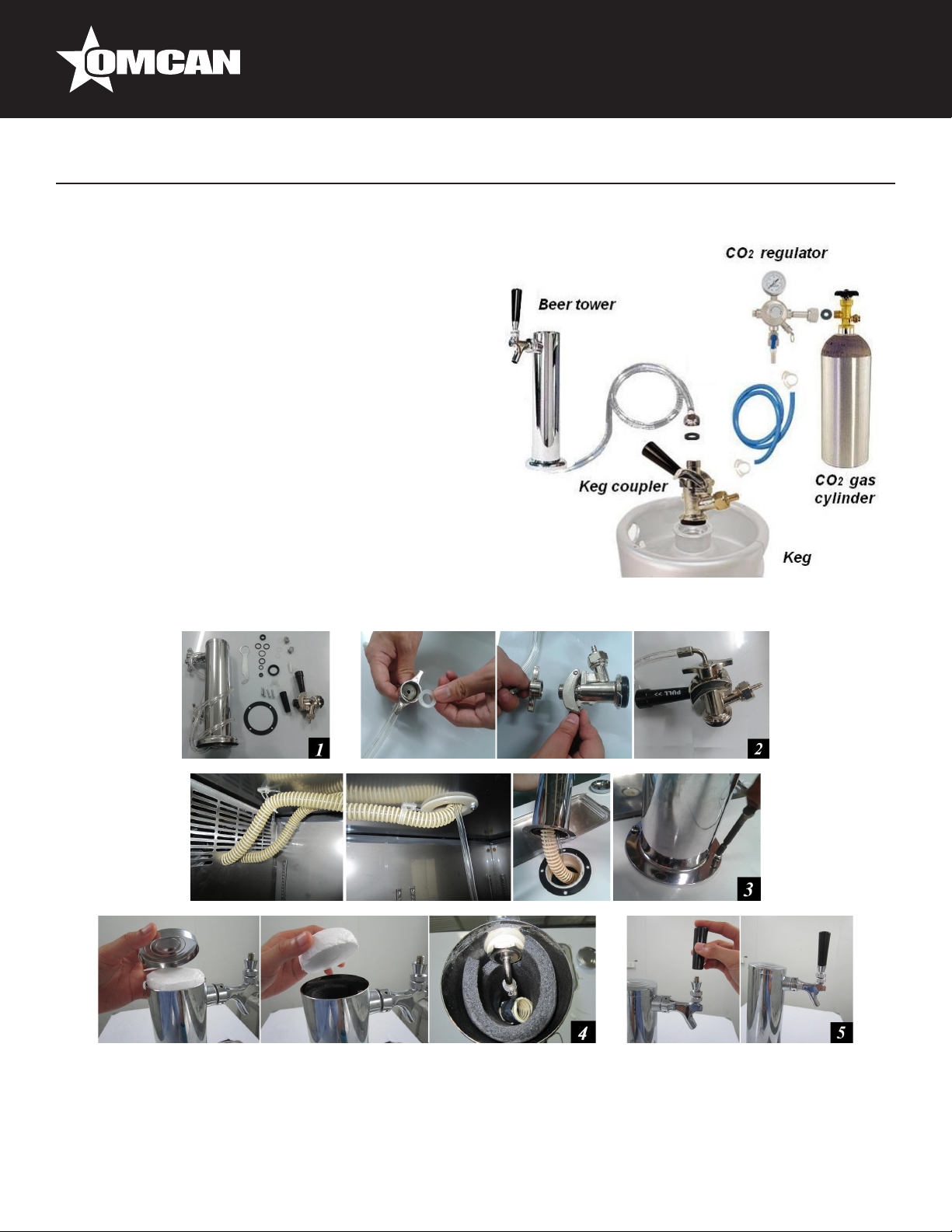
BEER DISPENSING SYSTEM
DRAFT BEER TOWER INSTALLATION
1. Beer tower contents.
2. Thread the beer line connector to the keg coupler.
3. Insert an air hose into the beer tower and secure the
beer tower to cabinet with the gasket under the beer
tower.
4. Make sure the air hose closes at the top of beer tower at all times. This is to keep the beer faucet cold.
5. Secure the handle onto beer faucet.
9
Page 10
Installation
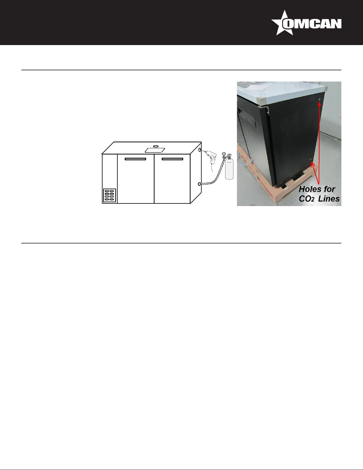
REMOTE CO2 GAS CYLINDER INSTALLATION
1. Remove the plug on the right wall of the machine with a pair of pliers.
2. Drill and make hole through the wall. Holes can be located in two
different areas. Reference above pictures for the position of the holes.
3. Insert the CO2 line through the hole.
4. Seal the hole around CO2 line with silicone sealer to prevent leakage
of cold air.
Operation
START UP
Plug in the cooler and the compressor is ready to operate.
• Temperature control set at #4 position gives the cooler an approximate temperature of 35°F. Allow unit to
function several hours, completely cooling cabinet before changing the control setting.
• Excessive tampering with the control could lead to service difculties. Should it ever become necessary to
replace the temperature control it should be ordered from your dealer or recommended service agent.
• Good air ow in your cooler is critical. Be careful to load product so that it neither presses against the back
wall nor comes within four (4) inches of the evaporator housing. Refrigerated air off the coil must circulate
down the back wall.
LIGHT SWITCH LOCATION:
The switch is located on the front of the evaporator housing toward the right of the cabinet. Open the front
door.
NOTE: If the unit is disconnected or shut off, wait ve (5) minutes before re-starting unit.
RECOMMENDATION
Before loading product the unit should be run for 2 to 3 days. This allows conrmation that the electrical wiring
and installation are correct and no shipping damage has occurred. Remember that the factory warranty does
10
Page 11
Operation
not cover product loss.
REPLACEMENT PARTS
We maintains a record of the cabinet model number and serial number for your cooler. If at any time during
the life of your cooler a replacement part is needed, call the factory ofce with the model number and serial
number of your unit to place an order for the part.
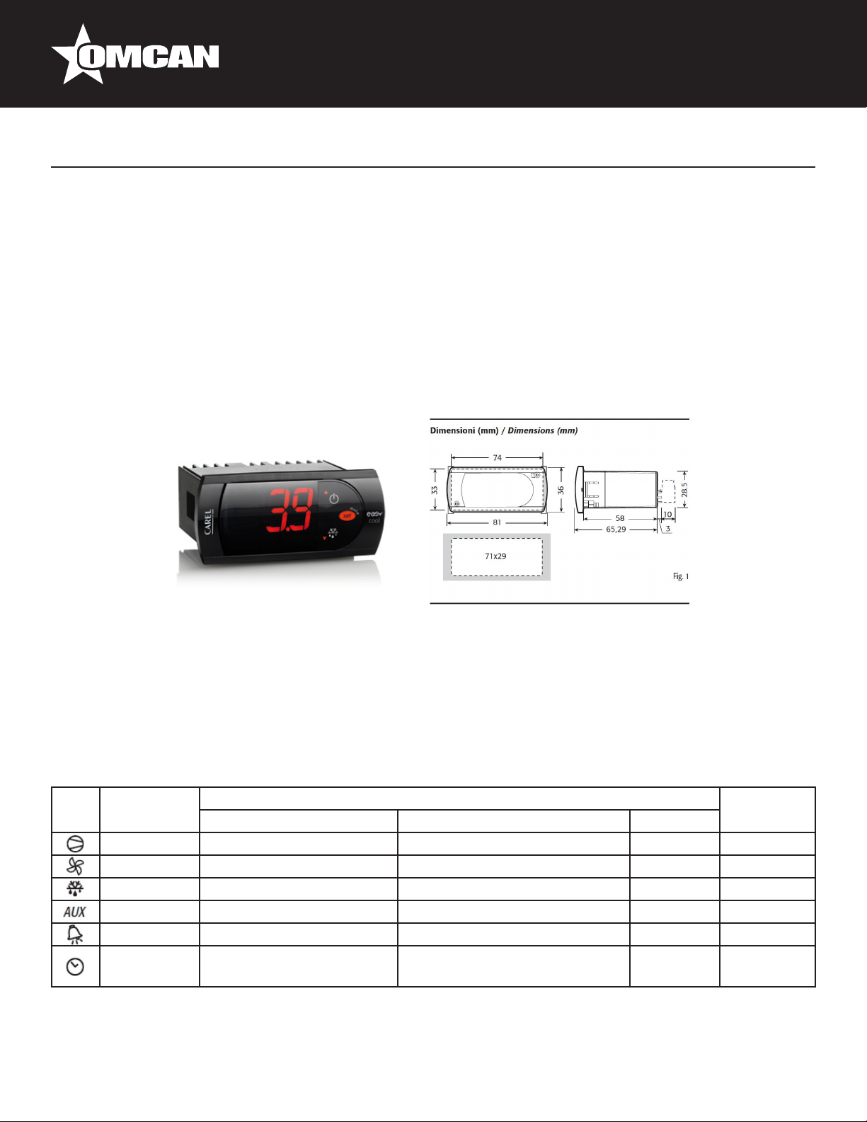
CONTROLLER INSTRUCTIONS
DIGITAL CONTROLLER MODEL: PJEZ FOR COOLER
DISPLAY AND FUNCTIONS
During normal operation, the controller displays the value of the probe set using parameter/4(=1 ambient
probe, default, = 2 second probe, = 3 third probe).In addition, the display has LEDs that indicate the activation
of the control functions (see Table 1), while the 3 buttons can be used to activate/deactivate some of the
functions(see Table 2).
LED’s and Associated Functions (Table 1)
Icon Function Normal Operation Start Up
ON OFF Blink
Compressor On Off Request ON
Fan On Off Request ON
Defrost On Off Request ON
Aux Output On Output Off - ON
Alarm All No Alarm - ON
Clock RTC tted and enabled, at
least 1 time band set
RTC not tted or disabled, not
even 1 time band set
- ON if RTC
tted
11
Page 12
Operation
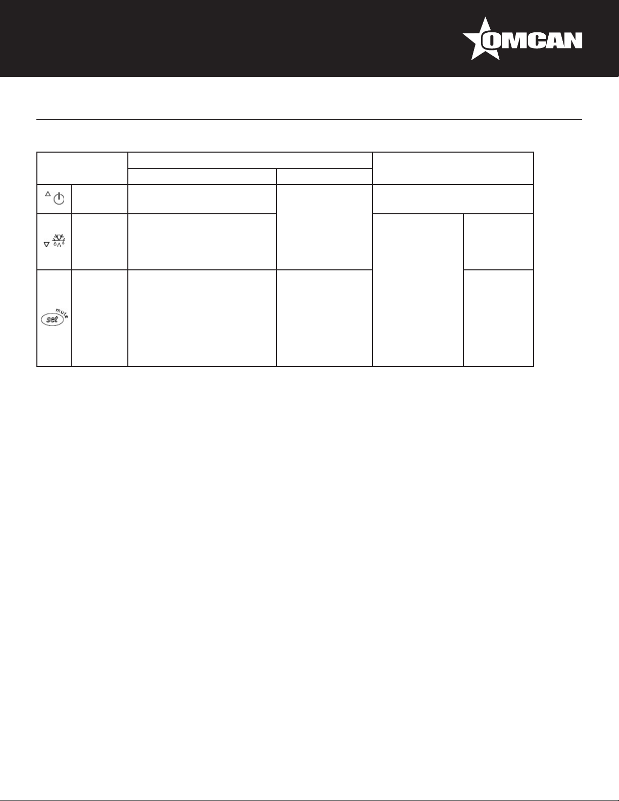
Table of Functions activated by the buttons - Models S, X, Y, C (Table 2)
Button Normal Operation Start Up
Pressing the Button Alone Pressed Together
Up
ON/OFF
Down
Defrost
Set Mute - 1 sec.: display/set the set
SETTING THE SET POINT (DESIRED TEMPERATURE)
More than 3 sec: toggle ON/
OFF
More than 3 sec: start/stop
defrost
point.
- more than 3 secs.: access
parameter setting menu
(enter password )
- mute audible alarm
(buzzer)
Start/Stop
continuous cycle
- For 1 sec.
-
Pressed
together
Start parameter
reset procedure
For 1 sec.
display
rmware
vers. code
RESET current EZY set
• Press SET for 1 sec, the set value will start ashing after a few moments.
• Increase or decrease the value using UP or DOWN.
• Press SET to conrm the new value.
SWITCHING THE DEVICE ON/OFF
Press UP for more than 3 sec. The control and defrost algorithms are now disabled and the Instrument
displays the message “OFF” alternating with the temperature read by the set probe.
MANUAL DEFROST
Press for DOWN more than 3 sec (the defrost starts only the temperature conditions are valid).
CONTINUOUS CYCLE
Press UP and DOWN together for more than 3 sec.
ACCESS AND SETTING TYPE F (FREQUENT) AND TYPE C (CONFIGURATION)
PARAMETERS
1. Press SET for 3 sec (the display will show “PS”).
2. • To access the type F and C parameter menu, enter the password “22” using UP/DOWN, press SET to
conrm.
• To access the F parameter menu only, press SET (without entering the password).
12
Page 13

Operation
3. Scroll inside the parameter menu using UP/DOWN.
• To display/set the values of the parameter displayed, press SET, then UP/DOWN and nally SET to
conrm the changes (returning to the parameter menu).
To save all the new values and exit the parameter menu, press SET for 3 sec.
To exit the menu without saving the changed values (exit by timeout) do not press any button for at least 60
sec.
MECHANICAL CONTROLLER INSTRUCTIONS
OFF: shut the compressor off.
Temperature range from 7 (coldest) to 1 (warmest).
CAUTION: Setting the temperature control to the coldest setting may cause the
evaporator coil to freeze and ice up. This will eventually result in a warmer cabinet
temperature.
Cleaning and Maintenance
Condensers accumulate dirt and dust and require cleaning every 30 days. Dirty condensers result in
compressor failure, product loss, and lost sales -- which are not covered by warranty.
Air is pulled through the condenser continuously along with dust, lint, grease, etc. If you keep the condenser
clean you will minimize your service expense and lower your electrical costs. The condenser requires
scheduled cleaning every days or as needed. A dirty condenser can result in non-warranted part and
compressor failures and product loss.
Proper cleaning involves removing debris from the condenser by using a soft brush or vacuuming the
condenser with a shop vac or using Co2, nitrogen or pressurized air.
If you cannot remove the debris adequately please call you refrigeration service company.
On most of the reach-in units the condenser is accessible at the rear of the unit. You must remove the cabinet
grill to expose the condenser. The condenser looks like a group of vertical ns. You need to be able to see
through the condenser for the unit to function at maximum capacity. Do not place lter material in front of
condensing coil. This material blocks air ow to the coil which is similar to having a dirty coil.
13
Page 14

Cleaning and Maintenance
CLEANING THE CONDENSER COIL
Required Tools:
• Phillips screwdriver.
• Stiff bristle brush.
• Adjustable wrench
When using electrical appliances basic safety precautions should be followed:
• Disconnect power to unit.
• Take off lower grill assembly by removing all screws.
• Remove bolts anchoring compressor assembly to frame rails and carefully slide out -- tube connections are
exible.
• Clean off accumulated dirt from condensing coil with the stiff bristle brush.
• Lift cardboard cover above fan at plastic plugs and carefully clean condenser coil and fan blades.
• After brushing condenser coil, vacuum dirt from coil and interior oor.
• Replace cardboard cover, carefully slide compressor assembly back into position and replace bolts.
• Reinstall louver assembly onto unit with appropriate fasteners and clips. Tighten all screws.
• Connect unit to power and check to see if condenser is running.
STAINLESS STEEL CARE AND CLEANING
Recommended cleaners for stainless steel
• Soap, ammonia and detergent medallion applied with a soft cloth or sponge for routine cleaning.
• Arcal 20, Loc-O-Nu Ecoshine provide a barrier lm for ngerprints and smears.
• Cameo, Talc, Zud First lmpression is for stubborn stains and discoloration. Rub in direction of polish lines.
• Easy-off and De-Grease It oven aid are excellent for removals on all nishes for grease-fatty acids, blood
and burnt-on foods.
• Any good commercial detergent can be applied with a sponge or soft cloth to remove grease and oil.
• Benet, Super Sheen, Sheila Shine are good for restoration/passiveness.
CAUTION: Do not use any steel wool, abrasive or chlorine based products to clean stainless steel surfaces.
Stainless Steel Enemies
There are three basic items that can break down stainless steel’s passivity layer and allow corrosion to occur.
1. Scratches from wire brushes, metal scrapers and steel pads are just a few examples of items that can be
abrasive to stainless steel’s surface.
2. Deposits left on stainless steel can leave spots. Hard water can leave spots. Hard water that is heated can
leave deposits if left to sit for too long. These deposits can cause the passive layer to break down and rust
stainless steel. All deposits left from food prep or service should be removed as quickly as possible.
3. Chlorides are present in table salt, food and water. Household and industrial cleaners are the worst type of
chlorides to use.
14
Page 15

Cleaning and Maintenance
8 Steps that can help prevent rust on stainless steel
1. Use the correct cleaning tools. Use non-abrasive tools when cleaning your stainless steel products. The
stainless steel’s passive layer will not be harmed by soft cloths and plastic scouring pads.
2. Clean along the polish lines. Polish lines or grain are visible on some stainless steel. Always scrub parallel
to visible lines. Use a plastic scouring pad or soft cloth when grain is not visible.
3. Use alkaline, alkaline chlorinated or non-chloride containing cleaners. While many traditional cleaners are
loaded with chlorides, the industry is providing an ever increasing choice of non-chloride cleaners. If unsure
of chloride content contact the cleaner supplier. If present cleaner contains chlorides, ask for an alternative.
Avoid cleaners containing quaternary salts as they can attack stainless steel causing pitting and rusting.
4. Water treatment. To reduce deposits, use soft water whenever possible. Installation of certain lters can be
an advantage. Contact a treatment specialist about proper water treatment.
5. Maintain cleanliness of food equipment. Use cleaners at recommended strength(alkaline, alkaline
chlorinated or non-chloride). Avoid buildup of hard stains by cleaning frequently.
6. When using chlorinated cleaners you must rinse and wipe dry immediately. It is better to wipe standing
cleaning agents and water as soon as possible. All stainless steel equipment to air dry. Oxygen helps
maintain the passivity lm on stainless steel.
7. Hydrochloric acid (muriatic acid) should never be used on stainless steel.
8. Regularly restore/clean stainless steel.
KEG BEER LINE CLEANING
1. Tools needed.
2. Pour cleaning solution and water into the pump bottle and connect it to the beer line.
3. Place a bucket under the faucet and open the beer faucet. Pump to remove the cleaning solution and
water. Continue to pump until all cleaning solution has exited. You can also ll the line and let it soak then
run through the line. After you have run the cleaning solution through, open the bottle and ll with water.
Repeat water rinsing until the line is free of cleaning chemicals.
15
Page 16

Cleaning and Maintenance
REFERENCE
Item Number Model Number Description
Beer Dispenser Single Solid Door with
50066 BD-CN-0007-HC
50063 BB-CN-0012-DH
50067 BD-CN-0019-HC
50064 BB-CN-0016-DH
50068 BD-CN-0023-HC
50065 BB-CN-0020-DH
50069 BD-CN-0032-HC
One Tap 6.5 cu ft / 186 L Capacity
110V/60HZ ETL cETLus INTERTEK
Cooler Back Bar 11.8 cu ft Capacity Solid
Door with Beer Dispenser 115V/60/1 NSF
ETL cETLus INTERTEK
Beer Dispenser Double Solid Doors
with One Tap 19 cu ft / 546 L Capacity
110V/60HZ ETL cETLus INTERTEK
Cooler Back Bar 15.8 cu ft Capacity Solid
Door with Beer Dispenser 115V/60/1 NSF
ETL cETLus INTERTEK
Beer Dispenser Double Solid Doors with
Two Taps 23.3 cu ft / 666 L Capacity
110V/60HZ ETL cETLus INTERTEK
Cooler Back Bar 19.6 cu ft Capacity Solid
Door with Beer Dispenser 115V/60/1 NSF
ETL cETLus INTERTEK
Beer Dispenser Three Solid Doors with
Two Taps 32 cu ft / 916 L Capacity
110V/60HZ ETL cETLus INTERTEK
Manufacturer Model
Number
UDD-1-HC
UDD-24-48-HC
UDD-2-HC
UDD-24-60-HC
UDD-3-HC
UDD-24-72-HC
UDD-4-HC
16
Page 17

Model BD-CN-0007-HC 50066
Parts Breakdown
17
Page 18

Parts Breakdown
Model BD-CN-0007-HC 50066
Item No. Description Position Item No. Description Position Item No. Description Position
AA581 Outer Drain Pan for UDD-1-HC 1 AA591 Stainless Steel Guard Rail for UDD-1-HC 17 AA123 Thermostat for UDD-1-HC 33
AA531 Rubber Pad for UDD-1-HC 2 AA359 Upper Right Hinge for UDD-1-HC 18 AA601 Caster without Brake for UDD-1-HC 34
AA582
AA583 Cabinet for UDD-1-HC 4 AA203 Evaporator for UDD-1-HC 20 AA128 Condenser Fan Motor for UDD-1-HC 36
AA360 Bottom Right Hinge for UDD-1-HC 5 AA592
AA584 Caster with Brake for UDD-1-HC 6 AA533 Beer Tower Kit - One Tap for UDD-1-HC 22 AA603 Belt for Gas Tank for UDD-1-HC 38
AA398 Hinge Axis for UDD-1-HC 7 AA593 Rubber Tube Plug for UDD-1-HC 23 AA604 Air Pipe Protection Board for UDD-1-HC 39
AA585 Door for UDD-1-HC 8 AA594 Evaporator Fan Holder for UDD-1-HC 24 AA605 Evaporator Cover for UDD-1-HC 40
AA586 Gasket for UDD-1-HC 9 AA595 Rubber Tube Cover for UDD-1-HC 25 AA606 Back Grill for UDD-1-HC 41
AA196 Key for UDD-1-HC 10 AA596 Thermometer for UDD-1-HC 26 AA607 Evaporator Fan Motor for UDD-1-HC 42
AA197 Lock for UDD-1-HC 11 AA597 Drain Hose Cover Board for UDD-1-HC 27 61219
AA587 Lock Plate for UDD-1-HC 12 AA528 Drain Hose for UDD-1-HC 28 AA388 Axis Cover for UDD-1-HC 44
AA588 Cover for Beer Drip Pan for UDD-1-HC 13 AA598 Fixer for Plastic Bottle for UDD-1-HC 29 AA418 Door Handle for UDD-1-HC 45
69703
AA589 Top Board for UDD-1-HC 15 AA600
AA590 Top Board Fixer for UDD-1-HC 16 AA127 Condenser for UDD-1-HC 32
Compressor Installation Board for
UDD-1-HC
Drain Connector for Beer Drip Pan for
UDD-1-HC
3 AA532 Corrugated Pipe for UDD-1-HC 19 AA602
Fan Motor Installation Panel for UDD1-HC
14
AA599
Plastic Bottle for Dripped Beer for
UDD-1-HC
Thermostat Installation Cover for
UDD-1-HC
21 64172 Compressor for UDD-1-HC 37
30 AA214
31
Base Board for Machine Room for
UDD-1-HC
Evaporator Fan Motor Blade for
UDD-1-HC
Waterproof Cover for Thermostat for
UDD-1-HC
35
43
46
18
Page 19

Model BB-CN-0012-DH 50063
Parts Breakdown
19
Page 20

Parts Breakdown
Model BB-CN-0012-DH 50063
Item No. Description Position Item No. Description Position Item No. Description Position
AA508 Right Door for UDD-24-48-HC 1 AA128 Condenser Fan Motor for UDD-24-48-HC 20 AA385 K Clip for UDD-24-48-HC 39
AA509 Left Door for UDD-24-48-HC 2 AA371 Filter for UDD-24-48-HC 21 AA386 Shelf for UDD-24-48-HC 40
AA359 Bottom Right Hinge for UDD-24-48-HC 3 64167 Compressor for UDD-24-48-HC 22 AA524 Upper Right Hinge for UDD-24-48-HC 41
AA185 Leveling Feet for UDD-24-48-HC 4 AA515 Inner Drain Pan for UDD-24-48-HC 23 AA388 Axis Cover for UDD-24-48-HC 42
AA360 Bottom Left Hinge for UDD-24-48-HC 5 AA373 Evaporator for UDD-24-48-HC 24 AA414 Gasket for UDD-24-48-HC 43
AA398 Bottom Hinge Axis for UDD-24-48-HC 6 AA516
AA124 Power Switch for UDD-24-48-HC 7 AA517
AA362 LED Light Switch for UDD-24-48-HC 8 AA518
AA123 Thermostat for UDD-24-48-HC 9 AA519 Evaporator Cover for UDD-24-48-HC 28 AA526 Upper Light Hinge for UDD-24-48-HC 47
AA510 Control Panel for UDD-24-48-HC 10 AA378
AA364 LED Power Supply for UDD-24-48-HC 11 AA379 Temperature Probe for UDD-24-48-HC 30 AA418 Door Handle for UDD-24-48-HC 49
AA365 Power Cord for UDD-24-48-HC 12 AA520
AA511 Back Grill for UDD-24-48-HC 13 AA208 Evaporator Fan Blade for UDD-24-48-HC 32 AA529 Plastic Connector for UDD-24-48-HC 51
AA216 Drain Hose for UDD-24-48-HC 14
AA512
AA513 Outer Drain Pan for UDD-24-48-HC 16 68296 LED Light for UDD-24-48-HC 35 AA532 Corrugated Pipe for UDD-24-48-HC 54
AA514
AA370 Condenser for UDD-24-48-HC 18 AA522 Top Board Fixer for UDD-24-48-HC 37 AA534
AA129 Filter Fixer for UDD-24-48-HC 19 AA523 K Strip for UDD-24-48-HC 38 69703
Handle of Compressor Installation Board
for UDD-24-48-HC
Condenser Installation Board for UDD24-48-HC
15 68809 Evaporator Fan Motor for UDD-24-48-HC 34 AA531 Rubber Pad for UDD-24-48-HC 53
17 AA521 Top Board for UDD-24-48-HC 36 AA533
AA381
Fixed Mounts for Back Grill for UDD24-48-HC
Compressor Installation Board for UDD24-48-HC
Compressor Component for UDD-2448-HC
Temperature Probe Fixer for UDD-2448-HC
Evaporator Fan Installation Board for
UDD-24-48-HC
Evaporator Fan Holder for UDD-2448-HC
25 AA196 Key for UDD-24-48-HC 44
26 AA525 Lock Plate for UDD-24-48-HC 45
27 AA197 Lock for UDD-24-48-HC 46
29 AA527 Cabinet for UDD-24-48-HC 48
31 AA528 Drain Hose for UDD-24-48-HC 50
33 AA530 Bafe for UDD-24-48-HC 52
Beer Tower Kit - One Tap for UDD-2448-HC
Cover for Beer Drip Pan for UDD-2448-HC
Drain Connector for Beer Drip Pan for
UDD-24-48-HC
55
56
57
20
Page 21

Model BD-CN-0019-HC 50067
Parts Breakdown
21
Page 22

Parts Breakdown
Model BD-CN-0019-HC 50067
Item No. Description Position Item No. Description Position Item No. Description Position
AA608 Right Door for UDD-2-HC 1 AA128 Condenser Fan Motor for UDD-2-HC 20 AA385 K Clip for UDD-2-HC 39
AA609 Left Door for UDD-2-HC 2 AA371 Filter for UDD-2-HC 21 AA624 Shelf for UDD-2-HC 40
AA359 Bottom Right Hinge for UDD-2-HC 3 64167 Compressor for UDD-2-HC 22 AA625 Upper Right Hinge for UDD-2-HC 41
AA185 Leveling Feet for UDD-2-HC 4 AA615 Inner Drain Pan for UDD-2-HC 23 AA388 Axis Cover for UDD-2-HC 42
AA360 Bottom Left Hinge for UDD-2-HC 5 AA373 Evaporator for UDD-2-HC 24 AA626 Gasket for UDD-2-HC 43
AA398 Bottom Hinge Axis for UDD-2-HC 6 AA616 Fixed Mounts for Back Grill for UDD-2-HC 25 AA196 Key for UDD-2-HC 44
AA124 Power Switch for UDD-2-HC 7 AA617
AA362 LED Light Switch for UDD-2-HC 8 AA618 Compressor Component for UDD-2-HC 27 AA197 Lock for UDD-2-HC 46
AA123 Thermostat for UDD-2-HC 9 AA619 Evaporator Cover for UDD-2-HC 28 AA628 Upper Light Hinge for UDD-2-HC 47
AA610 Control Panel for UDD-2-HC 10 AA378 Temperature Probe Fixer for UDD-2-HC 29 AA629 Cabinet for UDD-2-HC 48
AA364 LED Power Supply for UDD-2-HC 11 AA379 Temperature Probe for UDD-2-HC 30 AA418 Door Handle for UDD-2-HC 49
AA365 Power Cord for UDD-2-HC 12 AA620
AA611 Back Grill for UDD-2-HC 13 AA208 Evaporator Fan Blade for UDD-2-HC 32 AA529 Plastic Connector for UDD-2-HC 51
AA216 Drain Hose for UDD-2-HC 14 AA381 Evaporator Fan Holder for UDD-2-HC 33
AA612
AA613 Outer Drain Pan for UDD-2-HC 16 68296 LED Light for UDD-2-HC 35 AA532 Corrugated Pipe for UDD-2-HC 54
AA614
AA370 Condenser for UDD-2-HC 18 AA622 Top Board Fixer for UDD-2-HC 37 AA632 Cover for Beer Drip Pan for UDD-2-HC 56
AA129 Filter Fixer for UDD-2-HC 19 AA623 K Strip for UDD-2-HC 38 69703
Handle of Compressor Installation Board
for UDD-2-HC
Condenser Installation Board for
UDD-2-HC
15 68809 Evaporator Fan Motor for UDD-2-HC 34 AA631 Rubber Pad for UDD-2-HC 53
17 AA621 Top Board for UDD-2-HC 36 AA533 Beer Tower Kit - One Tap for UDD-2-HC 55
Compressor Installation Board for
UDD-2-HC
Evaporator Fan Installation Board for
UDD-2-HC
26 AA627 Lock Plate for UDD-2-HC 45
31 AA528 Drain Hose for UDD-2-HC 50
AA630 Bafe for UDD-2-HC 52
Drain Connector for Beer Drip Pan for
UDD-2-HC
57
22
Page 23

Model BB-CN-0016-DH 50064
Parts Breakdown
23
Page 24

Parts Breakdown
Model BB-CN-0016-DH 50064
Item No. Description Position Item No. Description Position Item No. Description Position
AA535 Right Door for UDD-24-60-HC 1 AA371 Filter for UDD-24-60-HC 21 AA551 Upper Right Hinge for UDD-24-60-HC 41
AA536 Left Door for UDD-24-60-HC 2 64167 Compressor for UDD-24-60-HC 22 AA388 Axis Cover for UDD-24-60-HC 42
AA359 Bottom Right Hinge for UDD-24-60-HC 3 AA542 Inner Drain Pan for UDD-24-60-HC 23 AA458 Gasket for UDD-24-60-HC 43
AA185 Leveling Feet for UDD-24-60-HC 4 AA373 Evaporator for UDD-24-60-HC 24 AA196 Key for UDD-24-60-HC 44
AA360 Bottom Left Hinge for UDD-24-60-HC 5 AA543
AA398 Bottom Hinge Axis for UDD-24-60-HC 6 AA544
AA124 Power Switch for UDD-24-60-HC 7 AA545
AA362 LED Light Switch for UDD-24-60-HC 8 AA546 Evaporator Cover for UDD-24-60-HC 28 AA554 Cabinet for UDD-24-60-HC 48
AA123 Thermostat for UDD-24-60-HC 9 AA378
AA537 Control Panel for UDD-24-60-HC 10 AA379 Temperature Probe for UDD-24-60-HC 30 AA528 Drain Hose for UDD-24-60-HC 50
AA364 LED Power Supply for UDD-24-60-HC 11 AA547
AA365 Power Cord for UDD-24-60-HC 12 AA208 Evaporator Fan Blade for UDD-24-60-HC 32 AA555 Bafe for UDD-24-60-HC 52
AA538 Back Grill for UDD-24-60-HC 13 AA381
AA216 Drain Hose for UDD-24-60-HC
AA539
AA540 Outer Drain Pan for UDD-24-60-HC 16 AA548 Top Board for UDD-24-60-HC 36 AA556
AA541
AA370 Condenser for UDD-24-60-HC 18 AA550 K Strip for UDD-24-60-HC 38 AA557 Plastic T-Junction for UDD-24-60-HC 58
AA129 Filter Fixer for UDD-24-60-HC 19 AA385 K Clip for UDD-24-60-HC 39
AA128 Condenser Fan Motor for UDD-24-60-HC 20 AA435 Shelf for UDD-24-60-HC 40
Handle of Compressor Installation Board
for UDD-24-60-HC
Condenser Installation Board for UDD24-60-HC
14 68809 Evaporator Fan Motor for UDD-24-60-HC 34 AA532 Corrugated Pipe for UDD-24-60-HC 54
15 68296 LED Light for UDD-24-60-HC 35 AA533
17 AA549 Top Board Fixer for UDD-24-60-HC 37 69703
Fixed Mounts for Back Grill for UDD24-60-HC
Compressor Installation Board for UDD24-60-HC
Compressor Component for UDD-2460-HC
Temperature Probe Fixer for UDD-2460-HC
Evaporator Fan Installation Board for
UDD-24-60-HC
Evaporator Fan Holder for UDD-2460-HC
25 AA552 Lock Plate for UDD-24-60-HC 45
26 AA197 Lock for UDD-24-60-HC 46
27 AA553 Upper Light Hinge for UDD-24-60-HC 47
29 AA418 Door Handle for UDD-24-60-HC 49
31 AA529 Plastic Connector for UDD-24-60-HC 51
33 AA531 Rubber Pad for UDD-24-60-HC 53
Beer Tower Kit - One Tap for UDD-2460-HC
Cover for Beer Drip Pan for UDD-2460-HC
Drain Connector for Beer Drip Pan for
UDD-24-60-HC
55
56
57
24
Page 25

Model BD-CN-0023-HC 50068
Parts Breakdown
25
Page 26

Parts Breakdown
Model BD-CN-0023-HC 50068
Item No. Description Position Item No. Description Position Item No. Description Position
AA633 Right Door for UDD-3-HC 1 AA371 Filter for UDD-3-HC 21 AA650 Upper Right Hinge for UDD-3-HC 41
AA634 Left Door for UDD-3-HC 2 64167 Compressor for UDD-3-HC 22 AA388 Axis Cover for UDD-3-HC 42
AA359 Bottom Right Hinge for UDD-3-HC 3 AA640 Inner Drain Pan for UDD-3-HC 23 AA626 Gasket for UDD-3-HC 43
AA185 Leveling Feet for UDD-3-HC 4 AA373 Evaporator for UDD-3-HC 24 AA196 Key for UDD-3-HC 44
AA360 Bottom Left Hinge for UDD-3-HC 5 AA641 Fixed Mounts for Back Grill for UDD-3-HC 25 AA651 Lock Plate for UDD-3-HC 45
AA398 Bottom Hinge Axis for UDD-3-HC 6 AA642
AA124 Power Switch for UDD-3-HC 7 AA643 Compressor Component for UDD-3-HC 27 AA652 Upper Light Hinge for UDD-3-HC 47
AA362 LED Light Switch for UDD-3-HC 8 AA644 Evaporator Cover for UDD-3-HC 28 AA653 Cabinet for UDD-3-HC 48
AA123 Thermostat for UDD-3-HC 9 AA378 Temperature Probe Fixer for UDD-3-HC 29 AA418 Door Handle for UDD-3-HC 49
AA635 Control Panel for UDD-3-HC 10 AA379 Temperature Probe for UDD-3-HC 30 AA528 Drain Hose for UDD-3-HC 50
AA364 LED Power Supply for UDD-3-HC 11 AA645
AA365 Power Cord for UDD-3-HC 12 AA208 Evaporator Fan Blade for UDD-3-HC 32 AA654 Bafe for UDD-3-HC 52
AA636 Back Grill for UDD-3-HC 13 AA381 Evaporator Fan Holder for UDD-3-HC 33 AA631 Rubber Pad for UDD-3-HC 53
AA216 Drain Hose for UDD-3-HC 14 68809 Evaporator Fan Motor for UDD-3-HC 34
AA637
AA638 Outer Drain Pan for UDD-3-HC 16 AA646 Top Board for UDD-3-HC 36 AA655 Cover for Beer Drip Pan for UDD-3-HC 56
AA639
AA370 Condenser for UDD-3-HC 18 AA648 K Strip for UDD-3-HC 38 AA557 Plastic T-Junction for UDD-3-HC 58
AA129 Filter Fixer for UDD-3-HC 19 AA385 K Clip for UDD-3-HC 39 AA656 Middle Beam Cover for UDD-3-HC 59
AA469 Condenser Fan Motor for UDD-3-HC 20 AA649 Shelf for UDD-3-HC 40
Handle of Compressor Installation Board
for UDD-3-HC
Condenser Installlation Board for
UDD-3-HC
15 68296 LED Light for UDD-3-HC 35 AA533 Beer Tower Kit - One Tap for UDD-3-HC 55
17 AA647 Top Board Fixer for UDD-3-HC 37 69703
Compressor Installation Board for
UDD-3-HC
Evaporator Fan Installation Board for
UDD-3-HC
26 AA197 Lock for UDD-3-HC 46
31 AA529 Plastic Connector for UDD-3-HC 51
AA532 Corrugated Pipe for UDD-3-HC 54
Drain Connector for Beer Drip Pan for
UDD-3-HC
57
26
Page 27

Model BB-CN-0020-DH 50065
Parts Breakdown
27
Page 28

Parts Breakdown
Model BB-CN-0020-DH 50065
Item No. Description Position Item No. Description Position Item No. Description Position
AA558 Right Door for UDD-24-72-HC 1 AA371 Filter for UDD-24-72-HC 21 AA574 Upper Right Hinge for UDD-24-72-HC 41
AA559 Left Door for UDD-24-72-HC 2 64173 Compressor for UDD-24-72-HC 22 AA388 Axis Cover for UDD-24-72-HC 42
AA359 Bottom Right Hinge for UDD-24-72-HC 3 AA565 Inner Drain Pan for UDD-24-72-HC 23 AA503 Gasket for UDD-24-72-HC 43
AA185 Leveling Feet for UDD-24-72-HC 4 AA373 Evaporator for UDD-24-72-HC 24 AA196 Key for UDD-24-72-HC 44
AA360 Bottom Left Hinge for UDD-24-72-HC 5 AA566
AA398 Bottom Hinge Axis for UDD-24-72-HC 6 AA567
AA124 Power Switch for UDD-24-72-HC 7 AA568
AA362 LED Light Switch for UDD-24-72-HC 8 AA569 Evaporator Cover for UDD-24-72-HC 28 AA577 Cabinet for UDD-24-72-HC 48
AA123 Thermostat for UDD-24-72-HC 9 AA378
AA560 Control Panel for UDD-24-72-HC 10 AA121 Temperature Probe for UDD-24-72-HC 30 AA484 Middle Shelf for UDD-24-72-HC 50
AA364 LED Power Supply for UDD-24-72-HC 11 AA570
AA365 Power Cord for UDD-24-72-HC 12 AA208 Evaporator Fan Blade for UDD-24-72-HC 32 AA579 Bafe for UDD-24-72-HC 52
AA561 Back Grill for UDD-24-72-HC 13 AA381
AA216 Drain Hose for UDD-24-72-HC
AA562
AA563 Outer Drain Pan for UDD-24-72-HC 16 AA571 Top Board for UDD-24-72-HC 36 AA532 Corrugated Pipe for UDD-24-72-HC 56
AA564
AA370 Condenser for UDD-24-72-HC 18 AA573 K Strip for UDD-24-72-HC 38 69703
AA129 Filter Fixer for UDD-24-72-HC 19 AA385 K Clip for UDD-24-72-HC 39 AA528 Drain Hose for UDD-24-72-HC 59
AA469 Condenser Fan Motor for UDD-24-72-HC 20 AA435 Shelf Left and Right for UDD-24-72-HC 40
Handle of Compressor Installation Board
for UDD-24-72-HC
Condenser Installation Board for UDD24-72-HC
14 68809 Evaporator Fan Motor for UDD-24-72-HC 34 AA531 Rubber Pad for UDD-24-72-HC 54
15 68296 LED Light for UDD-24-72-HC 35 AA533
17 AA572 Top Board Fixer for UDD-24-72-HC 37 AA580
Fixed Mounts for Back Grill for UDD24-72-HC
Compressor Installation Board for UDD24-72-HC
Compressor Component for UDD-2472-HC
Temperature Probe Fixer for UDD-2472-HC
Evaporator Fan Installation Board for
UDD-24-72-HC
Evaporator Fan Holder for UDD-2472-HC
25 AA575 Lock Plate for UDD-24-72-HC 45
26 AA197 Lock for UDD-24-72-HC 46
27 AA576 Upper Light Hinge for UDD-24-72-HC 47
29 AA418 Door Handle for UDD-24-72-HC 49
31 AA578 Air Deector for UDD-24-72-HC 51
33 AA529 Plastic Connector for UDD-24-72-HC 53
Beer Tower Kit - One Tap for UDD-2472-HC
Cover for Beer Drip Pan for UDD-2472-HC
Drain Connector for Beer Drip Pan for
UDD-24-72-HC
55
57
58
28
Page 29

Model BD-CN-0032-HC 50069
Parts Breakdown
29
Page 30

Parts Breakdown
Model BD-CN-0032-HC 50069
Item No. Description Position Item No. Description Position Item No. Description Position
AA657 Right Door for UDD-4-HC 1 AA371 Filter for UDD-4-HC 21 AA674 Upper Right Hinge for UDD-4-HC 41
AA658 Left Door for UDD-4-HC 2 64173 Compressor for UDD-4-HC 22 AA388 Axis Cover for UDD-4-HC 42
AA359 Bottom Right Hinge for UDD-4-HC 3 AA664 Inner Drain Pan for UDD-4-HC 23 AA626 Gasket for UDD-4-HC 43
AA185 Leveling Feet for UDD-4-HC 4 AA373 Evaporator for UDD-4-HC 24 AA196 Key for UDD-4-HC 44
AA360 Bottom Left Hinge for UDD-4-HC 5 AA665 Fixed Mounts for Back Grill for UDD-4-HC 25 AA675 Lock Plate for UDD-4-HC 45
AA398 Bottom Hinge Axis for UDD-4-HC 6 AA666
AA124 Power Switch for UDD-4-HC 7 AA667 Compressor Component for UDD-4-HC 27 AA676 Upper Light Hinge for UDD-4-HC 47
AA362 LED Light Switch for UDD-4-HC 8 AA668 Evaporator Cover for UDD-4-HC 28 AA677 Cabinet for UDD-4-HC 48
AA123 Thermostat for UDD-4-HC 9 AA378 Temperature Probe Fixer for UDD-4-HC 29 AA418 Door Handle for UDD-4-HC 49
AA659 Control Panel for UDD-4-HC 10 AA121 Temperature Probe for UDD-4-HC 30 AA678 Middle Beam Cover for UDD-4-HC 50
AA364 LED Power Supply for UDD-4-HC 11 AA669
AA365 Power Cord for UDD-4-HC 12 AA208 Evaporator Fan Blade for UDD-4-HC 32 AA680 Bafe for UDD-4-HC 52
AA660 Back Grill for UDD-4-HC 13 AA381 Evaporator Fan Holder for UDD-4-HC 33 AA529 Plastic Connector for UDD-4-HC 53
AA216 Drain Hose for UDD-4-HC 14 68809 Evaporator Fan Motor for UDD-4-HC 34
AA661
AA662 Outer Drain Pan for UDD-4-HC 16 AA670 Top Board for UDD-4-HC 36 AA532 Corrugated Pipe for UDD-4-HC 56
AA663
AA370 Condenser for UDD-4-HC 18 AA672 K Strip for UDD-4-HC 38 69703
AA129 Filter Fixer for UDD-4-HC 19 AA385 K Clip for UDD-4-HC 39 AA528 Drain Hose for UDD-4-HC 59
AA469 Condenser Fan Motor for UDD-4-HC 20 AA673 Shelf Left and Right for UDD-4-HC 40
Handle of Compressor Installation Board
for UDD-4-HC
Condenser Installation Board for
UDD-4-HC
15 68296 LED Light for UDD-4-HC 35 AA533 Beer Tower Kit - One Tap for UDD-4-HC 55
17 AA671 Top Board Fixer for UDD-4-HC 37 AA681 Cover for Beer Drip Pan for UDD-4-HC 57
Compressor Installation Board for
UDD-4-HC
Evaporator Fan Installation Board for
UDD-4-HC
26 AA197 Lock for UDD-4-HC 46
31 AA679 Air Deector for UDD-4-HC 51
AA631 Rubber Pad for UDD-4-HC 54
Drain Connector for Beer Drip Pan for
UDD-4-HC
58
30
Page 31

Model BD-CN-0007-HC 50066
Electrical Schematics
31
Page 32

Electrical Schematics
Model BB-CN-0012-DH 50063
32
Page 33

Model BD-CN-0019-HC 50067
Electrical Schematics
33
Page 34

Electrical Schematics
Model BB-CN-0016-DH 50064
34
Page 35

Model BD-CN-0023-HC 50068
Electrical Schematics
35
Page 36

Electrical Schematics
Model BB-CN-0020-DH 50065
36
Page 37

Model BD-CN-0032-HC 50069
Electrical Schematics
37
Page 38

Notes
________________________________________________________________________________________
________________________________________________________________________________________
________________________________________________________________________________________
________________________________________________________________________________________
________________________________________________________________________________________
________________________________________________________________________________________
________________________________________________________________________________________
________________________________________________________________________________________
________________________________________________________________________________________
________________________________________________________________________________________
________________________________________________________________________________________
________________________________________________________________________________________
________________________________________________________________________________________
________________________________________________________________________________________
________________________________________________________________________________________
________________________________________________________________________________________
________________________________________________________________________________________
________________________________________________________________________________________
________________________________________________________________________________________
________________________________________________________________________________________
________________________________________________________________________________________
________________________________________________________________________________________
________________________________________________________________________________________
________________________________________________________________________________________
38
Page 39

Warranty Registration
Thank you for purchasing an Omcan product. To register your warranty for this product, complete the information below, tear off the card at
the perforation and then send to the address specied below. You can also register online by visiting:
Merci d’avoir acheté un produit Omcan. Pour enregistrer votre garantie pour ce produit, complétez les informations ci-dessous, détachez la
carte au niveau de la perforation, puis l’envoyer à l’adresse spécié ci-dessous. Vous pouvez également vous inscrire en ligne en visitant:
Gracias por comprar un producto Omcan usted. Para registrar su garantía para este producto, complete la información a continuación,
cortar la tarjeta en la perforación y luego enviarlo a la dirección indicada a continuación. También puede registrarse en línea en:
https://omcan.com/warranty-registration/
For mailing in Canada
Pour postale au Canada
Por correo en Canadá
OMCAN
PRODUCT WARRANTY REGISTRATION
3115 Pepper Mill Court,
Mississauga, Ontario
Canada, L5L 4X5
PRODUCT WARRANTY REGISTRATION
4450 Witmer Industrial Estates, Unit 4,
For mailing in the US
Pour diffusion aux États-Unis
Por correo en los EE.UU.
OMCAN
Niagara Falls, New York
USA, 14305
or email to: service@omcan.com
Purchaser’s Information
Name: Company Name:
Address:
Telephone:
City: Province or State: Postal or Zip: Email Address:
Country: Type of Company:
Restaurant Bakery Deli
Dealer from which Purchased: Butcher Supermarket Caterer
Dealer City: Dealer Province or State: Institution (specify):
Invoice: Other (specify):
Model Name: Model Number: Serial Number:
Machine Description:
Date of Purchase (MM/DD/YYYY): Date of Installation (MM/DD/YYYY):
Would you like to extend the warranty? Yes No
Thank you for choosing Omcan | Merci d’avoir choisi Omcan | Gracias por elegir Omcan
39
Page 40

Since 1951 Omcan has grown to become a leading distributor of equipment and supplies to the North
American food service industry. Our success over these many years can be attributed to our commitment
to strengthen and develop new and existing relationships with our valued customers and manufacturers.
Today with partners in North America, Europe, Asia and South America, we continually work to improve
and grow the company. We strive to offer customers exceptional value through our qualied local sales
and service representatives who provide convenient access to over 5,000 globally sourced products.
Depuis 1951 Omcan a grandi pour devenir un des “leaders” de la distribution des équipements et
matériel pour l’industrie des services alimentaires en Amérique du Nord. Notre succès au cours de ces
nombreuses années peut être attribué à notre engagement à renforcer et à développer de nouvelles
et existantes relations avec nos clients et les fabricants de valeur. Aujourd’hui avec des partenaires en
Amérique du Nord, Europe, Asie et Amérique du Sud, nous travaillons continuellement à améliorer et
développer l’entreprise. Nous nous efforçons d’offrir à nos clients une valeur exceptionnelle grâce à
nos ventes locales qualiées et des représentants de service qui offrent un accès facile à plus de 5000
produits provenant du monde entier.
Desde 1951 Omcan ha crecido hasta convertirse en un líder en la distribución de equipos y suministros
de alimentos en América del Norte industria de servicios. Nuestro éxito en estos años se puede atribuir
a nuestro compromiso de fortalecer y desarrollar nuevas relaciones existentes con nuestros valiosos
clientes y fabricantes. Hoy con socios de América del Norte, Europa, Asia y América del Sur, que trabajan
continuamente para mejorar y crecer la empresa. Nos esforzamos por ofrecer a nuestros clientes valor
excepcional a través de nuestro local de ventas y representantes de los servicios que proporcionan un
fácil acceso a más de 5,000 productos con origen a nivel mundial.
 Loading...