

Page 1
Back Bar Bottle Coolers
Models BD-CN-0007-S, 0019-S, 0023-D, 0032-D, BB-CN-0012-D, 0016-D, 0020-D
Items 42941, 38008, 42942, 38009, 42943, 38010, 42944
Instruction Manual
Revised - 02/24/2017
Toll Free: 1-800-465-0234
Fax: 905-607-0234
Email: service@omcan.com
www.omcan.com
Page 2

Table of Contents
Model BD-CN-0007-S / Model BB-CN-0012-D / Model BD-CN-0019-S
Model BB-CN-0016-D / Model BD-CN-0023-D / Model BB-CN-0020-D
Model BD-CN-0032-D
Section
General Information
Safety and Warranty
Technical Specications
Installation
Operation
Cleaning and Maintenance
-------------------------------------------------------------------------------------- 8 - 10
------------------------------------------------------------------------------------- 10 - 13
--------------------------------------------------------------------------- 3 - 4
--------------------------------------------------------------------------- 4 - 6
-------------------------------------------------------------------------- 7
Page
--------------------------------------------------------------- 13 - 16
Parts Breakdown
Electrical Schematics
Notes
Warranty Registration
------------------------------------------------------------------------------------------------- 38
---------------------------------------------------------------------------- 17 - 30
---------------------------------------------------------------------- 31 - 37
---------------------------------------------------------------------------- 39
2
Page 3

General Information
Omcan Manufacturing and Distributing Company Inc., Food Machinery of America, Inc. dba Omcan
and Omcan Inc. are not responsible for any harm or injury caused due to any person’s improper or
negligent use of this equipment. The product shall only be operated by someone over the age of 18, of
sound mind, and not under the inuence of any drugs or alcohol, who has been trained in the correct
operation of this machine, and is wearing authorized, proper safety clothing. Any modication to the
machine voids any warranty, and may cause harm to individuals using the machine or in the vicinity of
the machine while in operation.
CHECK PACKAGE UPON ARRIVAL
Upon receipt of an Omcan shipment please inspect for external damage. If no damage is evident on the
external packaging, open carton to ensure all ordered items are within the box, and there is no concealed
damage to the machine. If the package has suffered rough handling, bumps or damage (visible or concealed),
please note it on the bill of lading before accepting the delivery and contact Omcan within 24 hours, so we may
initiate a claim with the carrier. A detailed report on the extent of the damage caused to the machine must be
lled out within three days, from the delivery date shown in the shipping documents. Omcan has no recourse
for damaged products that were shipped collect or third party.
Before operating any equipment, always read and familiarize yourself with all operation and safety
instructions.
Omcan would like to thank you for purchasing this machine. It’s of the utmost importance to save
these instructions for future reference. Also save the original box and packaging for shipping the
equipment if servicing or returning of the machine is required.
---------------------------------------------------------------------------------------------------------------------------------------------------
Omcan Fabrication et distribution Companie Limité et Food Machinery d’Amerique, dba Omcan et
Omcan Inc. ne sont pas responsables de tout dommage ou blessure causé du fait que toute personne
ait utilisé cet équipement de façon irrégulière. Le produit ne doit être exploité que par quelqu’un de
plus de 18 ans, saine d’esprit, et pas sous l’inuence d’une drogue ou d’acohol, qui a été formé pour
utiliser cette machine correctement, et est vêtu de vêtements de sécurité approprié. Toute modication
de la machine annule toute garantie, et peut causer un préjudice à des personnes utilisant la machine
ou des personnes à proximité de la machine pendant son fonctionnement.
VÉRIFIEZ LE COLIS DÈS RÉCEPTION
Dès réception d’une expédition d’Omcan veuillez inspecter pour dommages externes. Si aucun dommage
n’est visible sur l’emballage externe, ouvrez le carton an de s’assurer que tous les éléments commandés
sont dans la boîte, et il n’y a aucun dommage dissimulé à la machine. Si le colis n’a subi aucune mauvaises
manipulations, de bosses ou de dommages (visible ou cachée), notez-le sur le bond de livraison avant
d’accepter la livraison et contactez Omcan dans les 24 heures qui suivent, pour que nous puissions engager
une réclamation auprès du transporteur. Un rapport détaillé sur l’étendue des dommages causés à la machine
doit être rempli dans un délai de trois jours, à compter de la date de livraison indiquée dans les documents
d’expédition. Omcan n’a aucun droit de recours pour les produits endommagés qui ont été expédiées ou cueilli
par un tiers transporteur.
3
Page 4

General Information
Avant d’utiliser n’importe quel équipement, toujours lire et vous familiariser avec toutes les opérations
et les consignes de sécurité.
Omcan voudrais vous remercier d’avoir choisi cette machine. Il est primordial de conserver ces
instructions pour une référence ultérieure. Également conservez la boîte originale et l’emballage pour
l’expédition de l’équipement si l’entretien ou le retour de la machine est nécessaire.
---------------------------------------------------------------------------------------------------------------------------------------------------
Omcan Empresa De Fabricacion Y Distribucion Inc. Y Maquinaria De Alimentos De America, Inc. dba
Omcan y Omcan Inc. no son responsables de ningun daño o perjuicío causado por cualquier persona
inadecuada o el uso descuidado de este equipo. El producto solo podra ser operado por una persona
mayor de 18 años, en su sano juicio y no bajo alguna inuencia de droga o alcohol, y que este ha sido
entrenado en el correcto funcionamiento de esta máquina, y ésta usando ropa apropiada y autorizada.
Cualquier modicación a la máquina anúla la garantía y puede causar daños a las personas usando la
máquina mientras esta en el funcionamiento.
REVISE EL PAQUETE A SU LLEGADA
Tras la recepcion de un envio Omcan favor inspeccionar daños externos. Si no hay daños evidentes en el
empaque exterior, Habra el carton para asegurararse que todos los articulos solicitados ésten dentro de la
caja y no encuentre daños ocultos en la máquina. Si el paquete ha sufrido un manejo de poco cuidado, golpes
o daños (visible o oculto) por favor anote en la factura antes de aceptar la entrega y contacte Omcan dentro
de las 24 horas, de modo que podamos iniciar una reclamación con la compañia. Un informe detallado sobre
los daños causados a la máquina debe ser llenado en el plazo de tres días, desde la fecha de entrega que se
muestra en los documentos de envío. Omcan no tiene ningun recurso por productos dañados que se enviaron
a recoger por terceros.
Antes de utilizar cualquier equipo, siempre lea y familiarizarse con todas las instrucciones de
funcionamiento y seguridad.
Omcan le gustaría darle las gracias por la compra de esta máquina. Es de la mayor importancia para
salvar estas instrucciones para futuras consultas. Además, guarda la caja original y el embalaje para el
envío del equipo si servicio técnico o devolución de la máquina que se requiere.
Safety and Warranty
When using electrical appliances basic safety precautions should be followed:
• This cooler must be properly installed and located in accordance with the installation service
representative.
• Do not allow children to climb, stand or hang on the shelves in the cooler. They could damage the unit and
seriously injure themselves.
• Do not store or use gasoline or other ammable vapors and liquids in the vicinity of this or any other
appliance.
4
Page 5

Safety and Warranty
• Unplug the unit from the electrical outlet before cleaning or making repairs.
• Setting the temperature controls to the 0 (zero) position does not remove power to the light circuit,
perimeter heaters or evaporator fans.
NOTE: It is strongly recommended that any servicing be performed by an authorized instructions before it is
used.
ELECTRICAL SAFETY
Do not under any circumstances cut or remove the grounding prong from the power cord. For safety this
appliance must be properly grounded at all times.
• The power cord of this cooler is equipped with a grounding plug which mates with a standard grounding
wall outlet to minimize the possibility of electric shock hazard.
• If the outlet is a standard 2-prong outlet, it must be replaced with the properly grounded wall outlet. NEVER
USE AN ADAPTER PLUG!
• Have the wall outlet and circuit checked by a qualied electrician to make sure the outlet is properly
grounded. Check the incoming voltage with a voltmeter.
• DO NOT USE EXTENSION CORDS. The use of extension cords to connect the cooler will void warranty.
The unit must be close enough to the electrical supply so that extension cords are never used.
• The cooler should always be plugged into its own dedicated circuit with a voltage rating that matches the
rating plate. This provides the best performance and also prevents overloading wiring circuits which could
become a re hazard from overheated wires.
• Never unplug your cooler by pulling on the power cord. Always grip the plug rmly and pull straight out from
the outlet.
• Repair or replace immediately all power cords that have become frayed or otherwise damaged. Do not use
a power cord that has cracks or abrasion damage along its length or at either of its ends.
• When removing the cooler away from the wall be careful not to run over or damage the power cord.
• When the cooler is installed or used,all the packaging (including carton and plastic wrap) should be
removed.
• Keep the cooler stable to avoid vibration and noise.
• The cooler should be installed in a place with good ventilation and a space of at least 4” should be allowed
between the surrounding walls and the cabinet wall for air circulation.
• Unit should be placed far from any heating source to avoid decrease of refrigeration efciency.
• Install the cooler in a dry place to prevent rust from forming on the compartment body, which may affect the
electrical insulation.
It is strongly recommended that any servicing be performed by an authorized service representative.
NOTE: Wiring diagram can be referenced by removing the front louvered grill, and looking on the inside
cabinet wall electrical supply so that extension cords are never used.
CAUTION
• The cooler must be grounded correctly, never with a heating pipe and coal gas pipe.
• In case of damage to electrical cord and plug, please contact after sale service and never do it yourself.
5
Page 6

Safety and Warranty
• When unplugging unit, please grasp by the plug, not the cord.
• If the voltage is unstable, please select a suitable automatic voltage regulator.
• If the power cuts off, you should wait for at least 5 minutes before turning on the unit again to avoid
damage to the compressor.
• Never store any ammable, explosive or corrosive liquid or gas in or near the cooler.
PROPER DISPOSAL OF EQUIPMENT; DANGER! RISK OF CHILD ENTRAPMENT
Child entrapment and suffocation are not problems of the past. Junked or abandoned refrigerators are still
dangerous, even if they will sit for “just a few days.” If you are getting rid of an old refrigerator, please follow the
below instructions to help prevent a terrible accident.
• Remove the doors.
• Leave shelves in place to prevent children from easily climbing inside.
REFRIGERANT DISPOSAL
Your old refrigerator may have a cooling system that used “ozone depleting” chemicals. If you are throwing
away your old refrigerator, be sure the refrigerant is removed for proper disposal by a qualied service
technician. If you intentionally release any refrigerants you can be subject to nes and imprisonment under the
provisions of the environmental regulations.
1 YEAR PARTS AND LABOUR WARRANTY
Within the warranty period, contact Omcan Inc. at 1-800-465-0234 to schedule an Omcan authorized
service technician to repair the equipment locally.
Unauthorized maintenance will void the warranty. Warranty covers electrical and part failures, not
improper use.
Please see www.omcan.com/warranty.html for complete info.
WARNING:
The packaging components are classied as normal solid urban waste and can therefore be disposed of
without difculty.
In any case, for suitable recycling, we suggest disposing of the products separately (differentiated
waste) according to the current norms.
DO NOT DISCARD ANY PACKAGING MATERIALS IN THE ENVIRONMENT!
6
Page 7
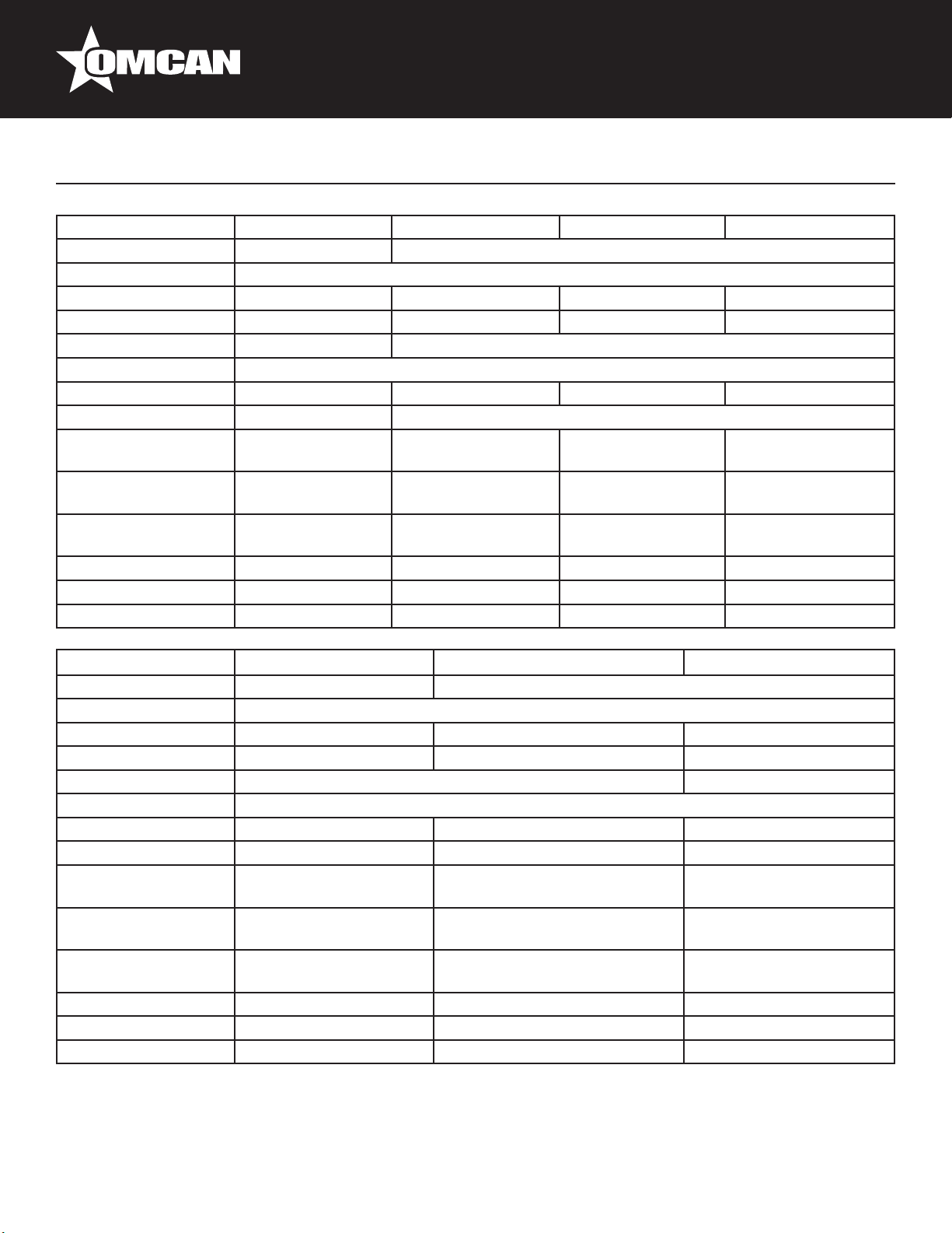
Technical Specications
Model BD-CN-0007-S BB-CN-0012-D BD-CN-0019-S BB-CN-0016-D
Number of Doors 1 2
Temperature Range 33 - 41°F / 0 - 5°C
Capacity 6.5 cu.ft. / 186 L 11.8 cu.ft. / 335 L 19 cu.ft. / 546 L 15.8 cu.ft. / 446 L
Number of Shelves - 4 2 4
Compressor HP 1/6+ 1/3+
Voltage 115V / 60Hz
Power 0.18 kW 0.44 kW 0.42 kW 0.46 kW
Amps 1.8A 6.4A
Dimensions (DWH)
Interior Dimensions
(DWH)
Packaging
Dimensions (DWH)
Weight 150 lbs. / 68 kg. 271 lbs. / 123 kg. 293 lb / 133 kg 326 lbs. / 148 kg.
Packaging Weight 187 lbs. / 85 kg. 315 lbs. / 143 kg. 337 lb / 153 kg 380 lbs. / 173 kg.
Item Number 42941 38008 42942 38009
772 x 597 x 984mm
30.4” x 23.5” x 38.8”
464 x 495 x 768mm
18.3” x 19.5” x 30.3”
826 x 654 x 1140mm
32.5” x 25.8” x 44.9”
620 x 1240 x 919mm
24.4” x 48.8” x 36.2”
508 x 919 x 787mm
20” x 36.2” x 31”
701 x 1300 x 1074mm
27.6” x 51.2” x 42.3”
705 x 1495 x 921mm
27.8” x 58.9” x 36.3”
594 x 1181 x 787mm
23.4” x 46.5” x 31”
775 x 1559 x 1060mm
30.5” x 61.4” x 41.8”
620 x 1544 x 919mm
24.4” x 60.8” x 36.2”
508 x 1224 x 787mm
20” x 48.2” x 31”
701 x 1610 x 1074mm
27.6” x 63.4” x 42.3”
Model BD-CN-0023-D BB-CN-0020-D BD-CN-0032-D
Number of Doors 2 3
Temperature Range 33 - 41°F / 0 - 5°C
Capacity 23.3 cu.ft. / 666 L 19.6 cu.ft. / 556 L 32 cu.ft. / 916 L
Number of Shelves 2 6 2
Compressor HP 1/3+ 3/4-
Voltage 115V / 60Hz
Power 0.54 kW 0.5 kW 0.64 kW
Amps 7.3A 7.4A 7.5A
Dimensions (DWH)
Interior Dimensions
(DWH)
Packaging
Dimensions (DWH)
Weight 348 lb / 158 kg 355 lbs. / 161 kg. 375 lb / 170 kg
Packaging Weight 331 lb / 150.1 kg 410 lbs. / 186 kg. 419 lb / 190 kg
Item Number 42943 38010 42944
705 x 1756 x 921mm
27.8” x 69.1” x 36.3”
594 x 1435 x 787mm
23.4” x 56.5” x 31”
787 x 1829 x 1067mm
31” x 72” x 42”
620 x 1849 x 919mm
24.4” x 72.8” x 36.2”
508 x 1529 x 787mm
20” x 60.2” x 31”
701 x 1910 x 1074mm
27.6” x 75.2” x 42.3”
705 x 2296 x 921mm
27.8” x 90.4” x 36.3”
594 x 1975 x 787mm
23.4” x 77.8” x 31”
775 x 2330 x 1060mm
30.5” x 91.8” x 41.8”
7
Page 8

Installation
Tools required: Phillips screw driver.
• Use a Phillips screw driver to remove the four (4) screws from the L-bracket connecting the unit to the
wood skid. Then remove the L-bracket from the unit.
• Remove skid by unscrewing all base rail anchor brackets. Place skid to the side.
• Carefully upright cabinet.
When lifting unit do not use the counter top as a lifting point. Also remember to leave cabinet upright
for 24-hours before plugging into power source.
• Set unit in its nal location. Make sure there is adequate ventilation in this location. Under extreme heat
conditions (+100°F / +38°C) an exhaust fan may be necessary.
• Proper leveling of the unit is critical to operating success (for non-mobile models). Effective condensate
removal and door operation will be affected by leveling.
• The cooler should be leveled front to back and side to side with a level.
Warning: Installation without proper ventilation will void the manufacturer’s warranty.
SEALING CABINET TO FLOOR
Step 1 - Position Cabinet
Allow one (1) inch between the wall and rear of the refrigerated bar equipment to assure proper ventilation.
Step 2 - Level Cabinet
Cabinet should be level side to side and front to back. Place a carpenter’s level in the interior cabinet oor in
four places:
A Position level in the inside oor of the unit near the door. Level should be parallel to cabinet front.
B Position level at the inside rear of cabinet. Level should be placed parallel to cabinet back.
C Perform similar procedures to steps A and B by placing the level on inside oor left and right sides parallel to
the depth of the cooler. Level cabinet.
Step 3 - Applying Sealant
• Draw an outline on the base of the oor.
• Raise and block the front side of the cabinet.
• Apply a bead of NSF Approved Sealant (see list below) to oor half an inch inside the outline drawn. The
bead must be heavy enough to seal the entire cabinet surface when it set down on the sealant.
• Raise and block the rear of the cabinet.
• Apply sealant on oor as outlined above on other 3 sides.
• Examine to see that the cabinet is sealed to oor around entire perimeter.
NSF APPROVED SEALANTS:
• Minnesota Mining #ECU800 Caulk.
• Minnesota Mining #ECU2185 Caulk.
8
Page 9
Installation
• Minnesota Mining #ECU1055 Bead.
• Minnesota Mining #ECU1202 Bead.
• Armstrong Cork - Rubber Caulk.
• Products Research Co #5000 Rubber Caulk.
• GE Silicone Sealer.
• Dow Corning Silicone Sealer.
NOTE: Asphalt oors are very susceptible to chemical
attack. A layer of tape on the oor prior to applying the
sealant will protect the oor.
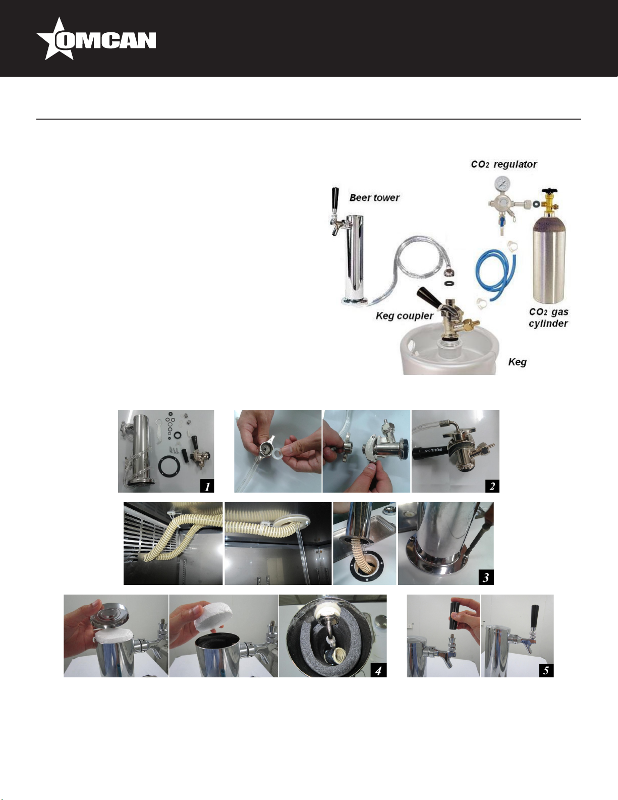
BEER DISPENSING SYSTEM
DRAFT BEER TOWER INSTALLATION
1. Beer tower contents.
2. Thread the beer line connector to the keg coupler.
3. Insert an air hose into the beer tower and secure the
beer tower to cabinet with the gasket under the beer
tower.
4. Make sure the air hose closes at the top of beer tower at all times. This is to keep the beer faucet cold.
5. Secure the handle onto beer faucet.
9
Page 10
Installation
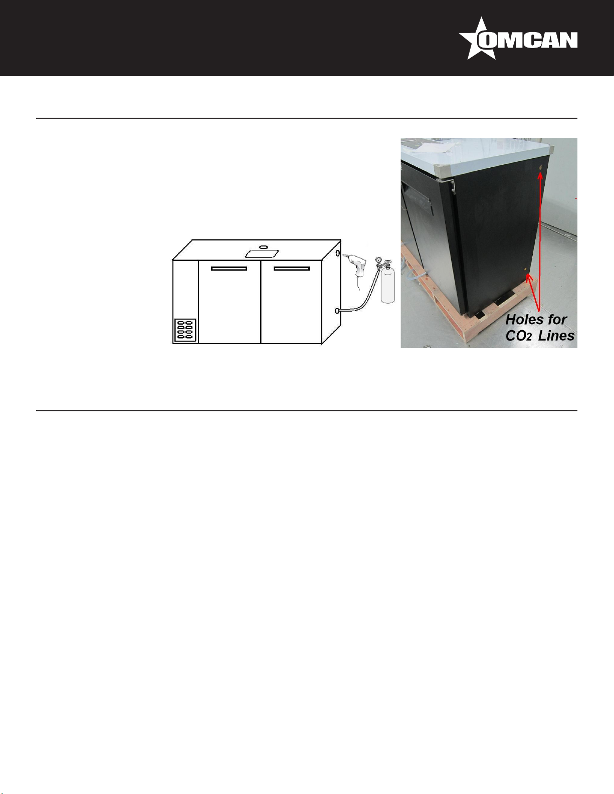
REMOTE CO2 GAS CYLINDER INSTALLATION
1. Remove the plug on the right wall of the machine with a pair of pliers.
2. Drill and make hole through the wall. Holes can be located in two
different areas. Reference above pictures for the position of the holes.
3. Insert the CO2 line through the hole.
4. Seal the hole around CO2 line with silicone sealer to prevent leakage
of cold air.
Operation
START UP
Plug in the cooler and the compressor is ready to operate.
• Temperature control set at #4 position gives the cooler an approximate temperature of 35°F. Allow unit to
function several hours, completely cooling cabinet before changing the control setting.
• Excessive tampering with the control could lead to service difculties. Should it ever become necessary to
replace the temperature control it should be ordered from your dealer or recommended service agent.
• Good air ow in your cooler is critical. Be careful to load product so that it neither presses against the back
wall nor comes within four (4) inches of the evaporator housing. Refrigerated air off the coil must circulate
down the back wall.
LIGHT SWITCH LOCATION:
The switch is located on the front of the evaporator housing toward the right of the cabinet. Open the front
door.
NOTE: If the unit is disconnected or shut off, wait ve (5) minutes before re-starting unit.
RECOMMENDATION
Before loading product the unit should be run for 2 to 3 days. This allows conrmation that the electrical wiring
and installation are correct and no shipping damage has occurred. Remember that the factory warranty does
10
Page 11
Operation
not cover product loss.
REPLACEMENT PARTS
We maintains a record of the cabinet model number and serial number for your cooler. If at any time during
the life of your cooler a replacement part is needed, call the factory ofce with the model number and serial
number of your unit to place an order for the part.
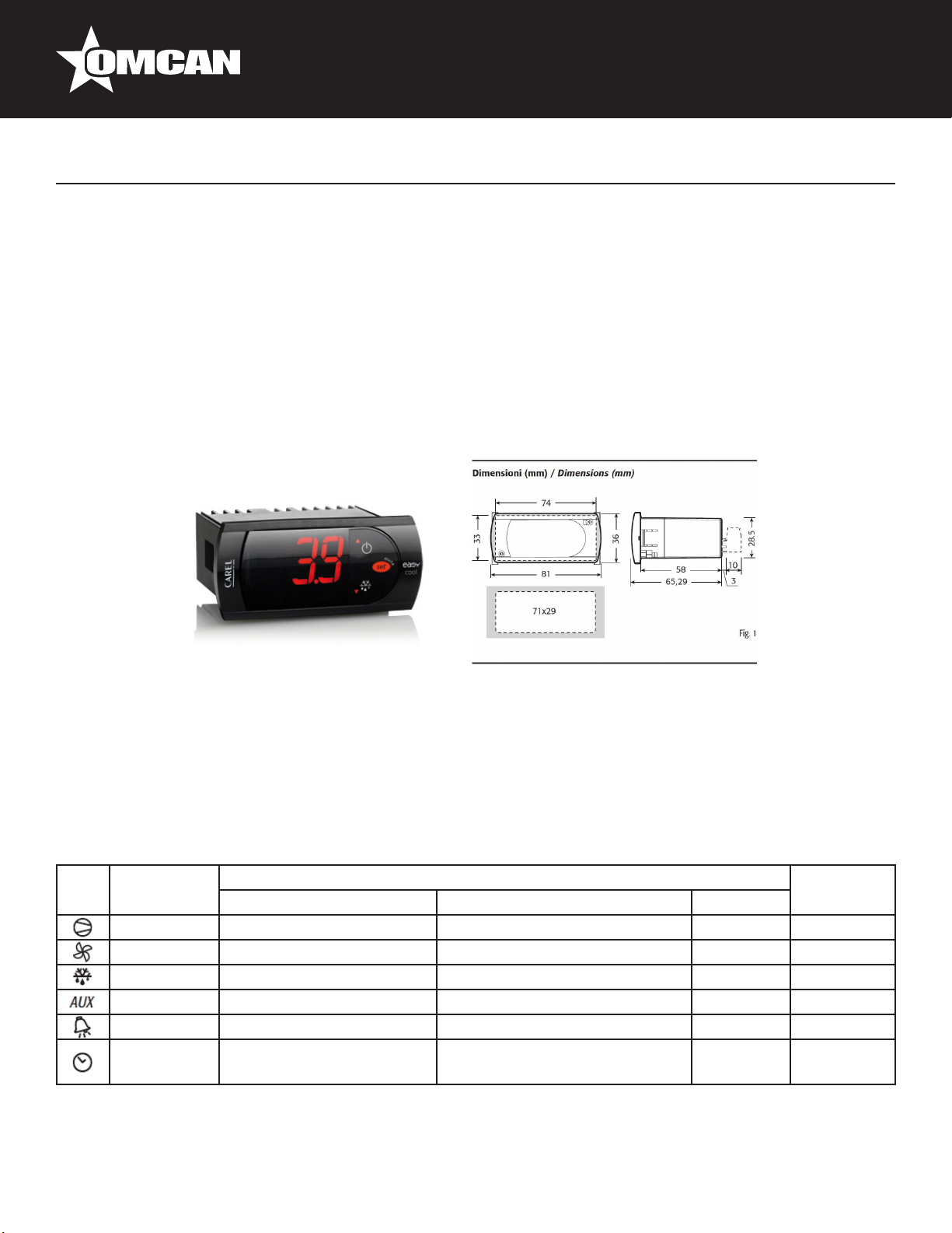
CONTROLLER INSTRUCTIONS
DIGITAL CONTROLLER MODEL: PJEZ FOR COOLER
DISPLAY AND FUNCTIONS
During normal operation, the controller displays the value of the probe set using parameter/4(=1 ambient
probe, default, = 2 second probe, = 3 third probe).In addition, the display has LEDs that indicate the activation
of the control functions (see Table 1),while the 3 buttons can be used to activate/deactivate some of the
functions(see Table 2).
LED’s and Associated Functions (Table 1)
Icon Function Normal Operation Start Up
ON OFF Blink
Compressor On Off Request ON
Fan On Off Request ON
Defrost On Off Request ON
Aux Output On Output Off - ON
Alarm All No Alarm - ON
Clock RTC tted and enabled, at
least 1 time band set
RTC not tted or disabled, not
even 1 time band set
- ON if RTC
tted
11
Page 12
Operation
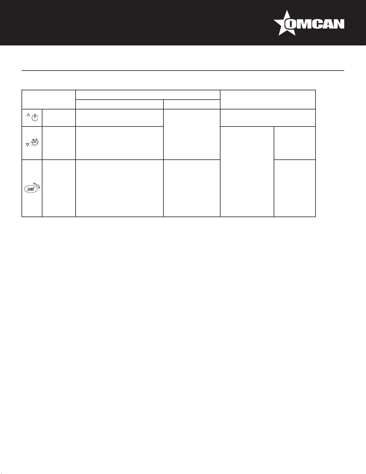
Table of Functions activated by the buttons - Models S, X, Y, C (Table 2)
Button Normal Operation Start Up
Pressing the Button Alone Pressed Together
Up
ON/OFF
Down
Defrost
Set Mute - 1 sec.: display/set the set
SETTING THE SET POINT (DESIRED TEMPERATURE)
More than 3 sec: toggle ON/
OFF
More than 3 sec: start/stop
defrost
point.
- more than 3 secs.: access
parameter setting menu
(enter password )
- mute audible alarm
(buzzer)
Start/Stop
continuous cycle
- For 1 sec.
-
Pressed
together
Start parameter
reset procedure
For 1 sec.
display
rmware
vers. code
RESET current EZY set
• Press SET for 1 sec, the set value will start ashing after a few moments.
• Increase or decrease the value using UP or DOWN.
• Press SET to conrm the new value.
SWITCHING THE DEVICE ON/OFF
Press UP for more than 3 sec. The control and defrost algorithms are now disabled and the Instrument
displays the message “OFF” alternating with the temperature read by the set probe.
MANUAL DEFROST
Press for DOWN more than 3 sec (the defrost starts only the temperature conditions are valid).
CONTINUOUS CYCLE
Press UP and DOWN together for more than 3 sec.
ACCESS AND SETTING TYPE F (FREQUENT) AND TYPE C (CONFIGURATION)
PARAMETERS
1. Press SET for 3 sec (the display will show “PS”).
2. • To access the type F and C parameter menu, enter the password “22” using UP/DOWN, press SET to
conrm.
• To access the F parameter menu only, press SET (without entering the password).
12
Page 13

Operation
3. Scroll inside the parameter menu using UP/DOWN.
• To display/set the values of the parameter displayed, press SET, then UP/DOWN and nally SET to
conrm the changes (returning to the parameter menu).
To save all the new values and exit the parameter menu, press SET for 3 sec.
To exit the menu without saving the changed values (exit by timeout) do not press any button for at least 60
sec.
MECHANICAL CONTROLLER INSTRUCTIONS
OFF: shut the compressor off.
Temperature range from 7 (coldest) to 1 (warmest).
CAUTION: Setting the temperature control to the coldest setting may cause the
evaporator coil to freeze and ice up. This will eventually result in a warmer cabinet
temperature.
Cleaning and Maintenance
Condensers accumulate dirt and dust and require cleaning every 30 days. Dirty condensers result in
compressor failure, product loss, and lost sales -- which are not covered by warranty.
Air is pulled through the condenser continuously along with dust, lint, grease, etc. If you keep the condenser
clean you will minimize your service expense and lower your electrical costs. The condenser requires
scheduled cleaning every days or as needed. A dirty condenser can result in non-warranted part and
compressor failures and product loss.
Proper cleaning involves removing debris from the condenser by using a soft brush or vacuuming the
condenser with a shop vac or using Co2, nitrogen or pressurized air.
If you cannot remove the debris adequately please call you refrigeration service company.
On most of the reach-in units the condenser is accessible at the rear of the unit. You must remove the cabinet
grill to expose the condenser. The condenser looks like a group of vertical ns. You need to be able to see
through the condenser for the unit to function at maximum capacity. Do not place lter material in front of
condensing coil. This material blocks air ow to the coil which is similar to having a dirty coil.
13
Page 14

Cleaning and Maintenance
CLEANING THE CONDENSER COIL
Required Tools:
• Phillips screwdriver.
• Stiff bristle brush.
• Adjustable wrench
When using electrical appliances basic safety precautions should be followed:
• Disconnect power to unit.
• Take off lower grill assembly by removing all screws.
• Remove bolts anchoring compressor assembly to frame rails and carefully slide out -- tube connections are
exible.
• Clean off accumulated dirt from condensing coil with the stiff bristle brush.
• Lift cardboard cover above fan at plastic plugs and carefully clean condenser coil and fan blades.
• After brushing condenser coil, vacuum dirt from coil and interior oor.
• Replace cardboard cover, carefully slide compressor assembly back into position and replace bolts.
• Reinstall louver assembly onto unit with appropriate fasteners and clips. Tighten all screws.
• Connect unit to power and check to see if condenser is running.
STAINLESS STEEL CARE AND CLEANING
Recommended cleaners for stainless steel
• Soap,ammonia and detergent medallion applied with a soft cloth or sponge for routine cleaning.
• Arcal 20,Loc-O-Nu Ecoshine provide a barrier lm for ngerprints and smears.
• Cameo, Talc, Zud First lmpression is for stubborn stains and discoloration. Rub in direction of polish lines.
• Easy-off and De-Grease It oven aid are excellent for removals on all nishes for grease-fatty acids,blood
and burnt-on foods.
• Any good commercial detergent can be applied with a sponge or soft cloth to remove grease and oil.
• Benet,Super Sheen,Sheila Shine are good for restoration/passiveness.
CAUTION: Do not use any steel wool, abrasive or chlorine based products to clean stainless steel surfaces.
Stainless Steel Enemies
There are three basic items that can break down stainless steel’s passivity layer and allow corrosion to occur.
1. Scratches from wire brushes, metal scrapers and steel pads are just a few examples of items that can be
abrasive to stainless steel’s surface.
2. Deposits left on stainless steel can leave spots. Hard water can leave spots. Hard water that is heated can
leave deposits if left to sit for too long. These deposits can cause the passive layer to break down and rust
stainless steel. All deposits left from food prep or service should be removed as quickly as possible.
3. Chlorides are present in table salt, food and water. Household and industrial cleaners are the worst type of
chlorides to use.
14
Page 15

Cleaning and Maintenance
8 Steps that can help prevent rust on stainless steel
1. Use the correct cleaning tools. Use non-abrasive tools when cleaning your stainless steel products. The
stainless steel’s passive layer will not be harmed by soft cloths and plastic scouring pads.
2. Clean along the polish lines. Polish lines or grain are visible on some stainless steel. Always scrub parallel
to visible lines. Use a plastic scouring pad or soft cloth when grain is not visible.
3. Use alkaline, alkaline chlorinated or non-chloride containing cleaners. While many traditional cleaners are
loaded with chlorides, the industry is providing an ever increasing choice of non-chloride cleaners. If unsure
of chloride content contact the cleaner supplier. If present cleaner contains chlorides, ask for an alternative.
Avoid cleaners containing quaternary salts as they can attack stainless steel causing pitting and rusting.
4. Water treatment. To reduce deposits, use soft water whenever possible. Installation of certain lters can be
an advantage. Contact a treatment specialist about proper water treatment.
5. Maintain cleanliness of food equipment. Use cleaners at recommended strength(alkaline, alkaline
chlorinated or non-chloride). Avoid buildup of hard stains by cleaning frequently.
6. When using chlorinated cleaners you must rinse and wipe dry immediately. It is better to wipe standing
cleaning agents and water as soon as possible. All stainless steel equipment to air dry. Oxygen helps
maintain the passivity lm on stainless steel.
7. Hydrochloric acid (muriatic acid) should never be used on stainless steel.
8. Regularly restore/clean stainless steel.
KEG BEER LINE CLEANING
1. Tools needed.
2. Pour cleaning solution and water into the pump bottle and connect it to the beer line.
3. Place a bucket under the faucet and open the beer faucet. Pump to remove the cleaning solution and
water. Continue to pump until all cleaning solution has exited. You can also ll the line and let it soak then
run through the line. After you have run the cleaning solution through, open the bottle and ll with water.
Repeat water rinsing until the line is free of cleaning chemicals.
15
Page 16

Cleaning and Maintenance
REFERENCE
Item Number Model Number Description Manufacturer Model Number
Beer Dispenser Single Solid Door with
42941 BD-CN-0007-S
38008 BD-CN-0012-D
42942 BD-CN-0019-S
38009 BD-CN-0016-D
42943 BD-CN-0023-D
38010 BD-CN-0020-D
42944 BD-CN-0032-D
One Tap 6.5 cu ft / 186 L Capacity
110V/60HZ ETL cETLus INTERTEK
Cooler Back Bar 11.8 cu ft Capacity Solid
Door with Beer Dispenser 115V/60/1 NSF
ETL cETLus INTERTEK
Beer Dispenser Double Solid Doors
with One Tap 19 cu ft / 546 L Capacity
110V/60HZ ETL cETLus INTERTEK
Cooler Back Bar 15.8 cu ft Capacity Solid
Door with Beer Dispenser 115V/60/1 NSF
ETL cETLus INTERTEK
Beer Dispenser Double Solid Doors with
Two Taps 23.3 cu ft / 666 L Capacity
110V/60HZ ETL cETLus INTERTEK
Cooler Back Bar 19.6 cu ft Capacity Solid
Door with Beer Dispenser 115V/60/1 NSF
ETL cETLus INTERTEK
Beer Dispenser Three Solid Doors with
Two Taps 32 cu ft / 916 L Capacity
110V/60HZ ETL cETLus INTERTEK
UDD-1
UDD-24-48
UDD-2
UDD-24-60
UDD-3
UDD-24-72
UDD-4
16
Page 17

Model BD-CN-0007-S 42941
Parts Breakdown
17
Page 18

Parts Breakdown
Model BD-CN-0007-S 42941
Item No. Description Position Item No. Description Position Item No. Description Position
71725 Cabinet for UDD1 1 71733 Back Cover for UDD1 18 71745
71726 Top Board for UDD1 2 26246 Front Castor for UDD1 19 71746 Rear Castor for UDD1 36
71727 Counter Top Tray for UDD1 3 71734 Solid Door for UDD1 20 71747 Counter Top Railing for UDD1 37
71843 Beer Tower for UDD1 4 26164 Spring Hinge of Solid Door for UDD1 21 71748 Exterior Water Tray for UDD1 38
71844 Cover of Top Tray for UDD1 5 26760 Axis Sleeve for UDD1 22 71749 Plastic Bottle for UDD1 39
71728
71851
73071 Drain Connector of Top Tray for UDD1 8 71736 Fan Motor Installation Panel for UDD1 25 71752 Tape of Plastic Bottle for UDD1 42
71847 Drain Hose of Top Tray for UDD1 9 71737 Evaporator Fan Motor Bracket for UDD1 26 71753 Door Seal for UDD1 43
37735 Fixed Block of Top Board for UDD1 10 71738 Evaporator Fan Motor for UDD1 27 26198 Door Lock for UDD1 44
37728 Bottom Right Hinge of Door for UDD1 11 71795 Blade of Evaporator Fan Motor for UDD1 28 71754 Air Tube of Beer Tower for UDD1 45
37734 Plate of Lock for UDD1 12 71739 Left Plate of Evaporator for UDD1 29 37694
71729 Bottom Plate of Machine Room for UDD1 13 71740 Right Plate of Evaporator for UDD1 30 37693
71730
71731 Condenser for UDD1 15 71742 Cover of Copper Pipe for UDD1 32 73072 Defrost Timer for UDD1 49
71732 Compressor for UDD1 16 71743 Cover of Inner Drain Hose for UDD1 33
37705 Condenser Fan Motor for UDD1 17 71744 Bracket of Defrost Timer for UDD1 34
Plastic Mounting Plate of Beer Tower
for UDD1
Drain Connector Nut of Top Tray for
UDD1
Compressor Unit Installation Board for
UDD1
6 37731 Upper Right Hinge for UDD1 23 71750 Plastic Pipe of CO2 Line for UDD1 40
7 71735 Evaporator for UDD1 24 71751
14 71741 Evaporator Cover for UDD1 31 37696
Reinforcing Plate of Interior Floor for
UDD1
Rubber Cover of Plastic Pipe of CO2
Line for UDD1
Mechanical Temperature Controller
for UDD1
Panel of Temperature Controller for
UDD1
Knob of Temperature Controller for
UDD1
35
41
46
47
48
18
Page 19

Model BB-CN-0012-D 38008
Parts Breakdown
19
Page 20

Parts Breakdown
Model BB-CN-0012-D 38008
Item No. Description Position Item No. Description Position Item No. Description Position
71788 Cabinet for UDD48 1 71810 Outer Drain Pan for UDD48 23 71832 Adjusted Feet for UDD48 45
71789 Top Board for UDD48 2 71811 Filter Fixer for UDD48 24 71833
71790 Inner Drain Pan for UDD48 3 71812 Filter for UDD48 25 71834 K Strip-2 Holes for UDD48 47
71791 Evaporator for UDD48 4 71813
71792 Fan Motor Installation Panel for UDD48 5 71814 Front Cover of Machine Room for UDD48 27 71836 Ballast of Light for UDD48 49
71793 Evaporator Fan Motor for UDD48 6 71815 Left Solid Door for UDD48 28 71837 Condenser Bracket for UDD48 50
71794 Evaporator Fan Motor Holder for UDD48 7 71816 Solid Door Gasket for UDD48 29 71838 Temperature Display for UDD48 51
71795
71796 Evaporator Cover for UDD48 9 71818 Axis Sleeve for UDD48 31 71840
71797 Temperature Control Panel for UDD48 10 71819 Bottom Right Hinge for UDD48 32 71841
71798 Mechanical Thermostat for UDD48 11 71820 Bottom Left Hinge for UDD48 33 71842 Spring Hinge for UDD48 55
71799 Temperature Control Knob for UDD48 12 71821 Upper Right Hinge for UDD48 34 71843 Beer Tower for UDD48 56
71800 Light Switch for UDD48 13 71822 Upper Left Hinge for UDD48 35 71844 Cover of Top Tray for UDD48 57
71801 Bracket of Lateral Cover for UDD48 14 71823 Plate of Lock for Right Door for UDD48 36 71845 Cover of CO2 Line for UDD48 58
71802
71803 Condenser for UDD48 16 71825 Fixed Block for Worktop for UDD48 38 71847 Drain Hose of Top Tray for UDD48 60
71804 Compressor for UDD48 17 71826 K Strip-4 Holes for UDD48 39 71848 L Shape Connector for UDD48 61
71805 Wiring Box of Compressor for UDD48 18 71827 K Clip for UDD48 40 71849 Rubber Pad for UDD48 62
71806 Start Capacitor for UDD48 19 71828 Shelf for UDD48 41 71850 Drain Connector of Top Tray for UDD48 63
71807 Overload Protector for UDD48 20 71829 LED Light for UDD48 42 71851
71808 Starter for UDD48 21 71830 Drain Hose for UDD48 43 71852 Air Tube for UDD48 65
71809 Condenser Fan Motor for UDD48 22 71831 Power Cord for UDD48 44
Blade of Evaporator Fan Motor for
UDD48
Compressor Unit Installation Board for
UDD48
8 71817 Right Solid Door for UDD48 30 71839
15 71824 Bottom Gasket of Compressor for UDD48 37 71846 Cover of L Shape Connector for UDD48 59
Lateral Cover of Machine Room for
UDD48
26 71835
Stop Block of Compressor Unit
Installation Board for UDD48
Handle of Compressor Unit Installation
Board for UDD48
Transformer of Temperature Display
for UDD48
Transformer Bracket of Temperature
Display for UDD48
Sensor of Temperature Display for
UDD48
Drain Connector Nut of Top Tray for
UDD48
46
48
52
53
54
64
20
Page 21

Model BD-CN-0019-S 42942
Parts Breakdown
21
Page 22

Parts Breakdown
Model BD-CN-0019-S 42942
Item No. Description Position Item No. Description Position Item No. Description Position
71755 Cabinet for UDD2 1 26188 Filter Base D25 for UDD2 24 28311
71756 Top Board for UDD2 2 26189 Filter D25x140 for UDD2 25 71834 K Strip 2 Holes for UDD2 47
37685 Inner Drain Pan for UDD2 3 71761 Lateral Cover for UDD2 26 71835
71757 Evaporator for UDD2 4 37708 Front Cover of Machine Room for UDD2 27 71836 Ballast for UDD2 49
71758 Fan Motor Installation Panel for UDD2 5 71762 Left Door (Solid) for UDD2 28 71837 Condenser Installation Board for UDD2 50
37688 Evaporator Fan Motor for UDD2 6 71763 Door Gasket (Solid) for UDD2 29 71838 Temp Display for UDD2 51
37689 Evaporator Fan Motor Holder for UDD2 7 71764 Right Door (Solid) for UDD2 30 71839 Transformer for Temp Display for UDD2 52
37690 Evaporator Fan Motor Blade for UDD2 8 26760 Axis Sleeve for UDD2 31 71840
71759 Evaporator Cover for UDD2 9 37728 Lower Right Hinge for UDD2 32 71841 Temp Sensor for Temp Display for UDD2 54
37693 Temperature Control Panel for UDD2 10 37730 Lower Left Hinge for UDD2 33 26164 Spring Hinge for UDD2 55
37694 Temperature Controller for UDD2 11 37731 Upper Right Hinge for UDD2 34 71843 Beer Tower for UDD2 56
37697 Lamp Switch for UDD2 13 37732 Upper Left Hinge for UDD2 35 71844 Cover of Top Tray for UDD2 57
71760 Bracket of Lateral Cover for UDD2 14 37734 Plate of Lock for UDD2 36 71845 CO2 Pipe Hole Cover for UDD2 58
37699
37700 Condenser 4R11K150L for UDD2 16 37735 Fixed Block of Top Board for UDD2 38 71847 Drain Hose of Top Tray for UDD2 60
26183 Compressor NE6187Z for UDD2 17 37736 K Strip 4 Holes for UDD2 39 71848 L Shape Connector for UDD2 61
37701 Splice Box for UDD2 18 26884 K Clip for UDD2 40 71766 Rubber Pad for UDD2 62
37702 Start Capacitor for UDD2 19 71774 Shelf (Left & Right) for UDD2 41 73075 Beer Tray Drain Plug for UDD2 63
37703 Overload Protector for UDD2 20 37741 LED Bulb for UDD2 42 73076 Beer Tray Drain Plug Nut for UDD2 64
37704 Starter for UDD2 21 26203 Drain Hose φ16 for UDD2 43 71767 Air Pipe for UDD2 65
37705
37706 Outer Drain Pan for UDD2 23 28236 Adjustable Feet M12x45 for UDD2 45
Compressor Unit Installation Board for
UDD2
Condenser Fan Motor RAM4715 for
UDD2
15 73073 Rubber Base of Compressor for UDD2 37 73074 Bottom Drain Plug Cover for UDD2 59
22 26205 Power Cord 16 AWG for UDD2 44 71768 Middle Beam Cover for UDD2 66
Installation Board Limited Block for
UDD2
Handle of Compressor Unit Installation
Board for UDD2
Temp Display Transformer Holder for
UDD2
46
48
53
22
Page 23

Model BB-CN-0016-D 38009
Parts Breakdown
23
Page 24

Parts Breakdown
Model BB-CN-0016-D 38009
Item No. Description Position Item No. Description Position Item No. Description Position
71853 Cabinet for UDD60 1 71876 Filter Fixer for UDD60 24 71899 K Strip-2 Holes for UDD60 47
71854 Top Board for UDD60 2 71877 Filter for UDD60 25 71900
71855 Inner Drain Pan for UDD60 3 71878
71856 Evaporator for UDD60 4 71879 Front Cover of Machine Room for UDD60 27 71902 Condenser Bracket for UDD60 50
71857 Fan Motor Installation Panel for UDD60 5 71880 Left Solid Door for UDD60 28 71903 Temperature Display for UDD60 51
71858 Evaporator Fan Motor for UDD60 6 71881 Solid Door Gasket for UDD60 29 71904
71859 Evaporator Fan Motor Holder for UDD60 7 71882 Right Solid Door for UDD60 30 71905
71860
71861 Evaporator Cover for UDD60 9 71884 Bottom Right Hinge for UDD60 32 71907 Spring Hinge for UDD60 55
71862 Temperature Control Panel for UDD60 10 71885 Bottom Left Hinge for UDD60 33 71908 Beer Tower for UDD60 56
71863 Mechanical Thermostat for UDD60 11 71886 Upper Right Hinge for UDD60 34 71909 Cover of Top Tray for UDD60 57
71864 Temperature Control Knob for UDD60 12 71887 Upper Left Hinge for UDD60 35 71910 Cover of CO2 Line for UDD60 58
71865 Light Switch for UDD60 13 71888 Plate of Lock for Right Door for UDD60 36 71911 Cover of L Shape Connector for UDD60 59
71866 Bracket of Lateral Cover for UDD60 14 71889 Bottom Gasket of Compressor for UDD60 37 71912 Drain Hose of Top Tray for UDD60 60
71867
71868 Condenser for UDD60 16 71891 K Strip-4 Holes for UDD60 39 71914 Rubber Pad for UDD60 62
71869 Compressor for UDD60 17 71892 K Clip for UDD60 40 71915 Drain Connector of Top Tray for UDD60 63
71870 Wiring Box of Compressor for UDD60 18 71893 Shelf for UDD60 41 71916
71871 Start Capacitor for UDD60 19 71894 LED Light for UDD60 42 71917 Air Tube of Left Beer Tower for UDD60 65
71872 Overload Protector for UDD60 20 71895 Drain Hose for UDD60 43 71918 Air Tube of Right Beer Tower for UDD60 66
71873 Starter for UDD60 21 71896 Power Cord for UDD60 44 71778 Short Drain Hose of Top Tray for UDD60 67
71874 Condenser Fan Motor for UDD60 22 71897 Adjusted Feet for UDD60 45 71779 T Shape Connector for UDD60 68
71875 Outer Drain Pan for UDD60 23 71898
Blade of Evaporator Fan Motor for
UDD60
Compressor Unit Installation Board for
UDD60
8 71883 Axis Sleeve for UDD60 31 71906
15 71890 Fixed Block for Worktop for UDD60 38 71913 L Shape Connector for UDD60 61
Lateral Cover of Machine Room for
UDD60
Stop Block of Compressor Unit
Installation Board for UDD60
26 71901 Ballast of Light for UDD60 49
46
Handle of Compressor Unit Installation
Board for UDD60
Transformer of Temperature Display
for UDD60
Transformer Bracket of Temperature
Display for UDD60
Sensor of Temperature Display for
UDD60
Drain Connector Nut of Top Tray for
UDD60
48
52
53
54
64
24
Page 25

Model BD-CN-0023-D 42943
Parts Breakdown
25
Page 26

Parts Breakdown
Model BD-CN-0023-D 42943
Item No. Description Position Item No. Description Position Item No. Description Position
71769 Cabinet for UDD3 1 26189 Filter D25x140 for UDD3 25 71835
71770 Top Board for UDD3 2 71761 Lateral Cover for UDD3 26 71836 Ballast for UDD3 49
37685 Inner Drain Pan for UDD3 3 37708 Front Cover of Machine Room for UDD3 27 71837 Condenser Installation Board for UDD3 50
71757 Evaporator for UDD3 4 71762 Left Door (Solid) for UDD3 28 27067 Temp Display for UDD3 51
71771 Fan Motor Installation Panel for UDD3 5 71763 Door Gasket (Solid) for UDD3 29 71839 Transformer for Temp Display for UDD3 52
37688 Evaporator Fan Motor for UDD3 6 71764 Right Door (Solid) for UDD3 30 71840
37689 Evaporator Fan Motor Holder for UDD3 7 26760 Axis Sleeve for UDD3 31 71841 Temp Sensor for Temp Display for UDD3 54
37690 Evaporator Fan Motor Blade for UDD3 8 37728 Lower Right Hinge for UDD3 32 26164 Spring Hinge for UDD3 55
71772 Evaporator Cover for UDD3 9 37730 Lower Left Hinge for UDD3 33 71843 Beer Tower for UDD3 56
37693 Temperature Control Panel for UDD3 10 37731 Upper Right Hinge for UDD3 34 71844 Cover of Top Tray for UDD3 57
37694 Temperature Controller for UDD3 11 37732 Upper Left Hinge for UDD3 35 71845 CO2 Pipe Hole Cover for UDD3 58
37697 Lamp Switch for UDD3 13 37734 Plate of Lock for UDD3 36 73078 Bottom Drain Plug Cover for UDD3 59
71760 Bracket of Lateral Cover for UDD3 14 73077 Rubber Base of Compressor for UDD3 37 71847 Drain Hose of Top Tray (Long) for UDD3 60
37699
37700 Condenser 4R11K150L for UDD3 16 37736 K Strip 4 Holes for UDD3 39 71775 Rubber Pad for UDD3 62
26183 Compressor NE6187Z for UDD3 17 26884 K Clip for UDD3 40 73079 Beer Tray Drain Plug for UDD3 63
37701 Splice Box for UDD3 18 71774 Shelf (Left & Right) for UDD3 41 73080 Beer Tray Drain Plug Nut for UDD3 64
37702 Start Capacitor for UDD3 19 37741 LED Bulb for UDD3 42 71776 Air Pipe (Short) for UDD3 65
37703 Overload Protector for UDD3 20 26203 Drain Hose φ16 for UDD3 43 71777 Air Pipe (Long) for UDD3 66
37704 Starter for UDD3 21 26205 Power Cord 16AWG for UDD3 44 71778 Drain Hose of Top Tray (Short) for UDD3 67
37705
37706 Outer Drain Pan for UDD3 23 37754 Installation Board Limited Block for UDD3 46 71780 Middle Beam Cover for UDD3 69
26188 Filter Base D25 for UDD3 24 71834 K Strip 2 Holes for UDD3 47
Compressor Unit Installation Board for
UDD3
Condenser Fan Motor RAM4715 for
UDD3
15
22 28236 Adjustable Feet M12x45 for UDD3 45 71779 T Shape Connector for UDD3 68
37735 Fixed Block of Top Board for UDD3 38 71848 L Shape Connector for UDD3 61
Handle of Compressor Unit Installation
Board for UDD3
Temp Display Transformer Holder for
UDD3
48
53
26
Page 27

Model BB-CN-0020-D 38010
Parts Breakdown
27
Page 28

Parts Breakdown
Model BB-CN-0020-D 38010
Item No. Description Position Item No. Description Position Item No. Description Position
71919 Cabinet for UDD72 1 71942 Filter Fixer for UDD72 24 71965 K Strip-2 Holes for UDD72 47
71920 Top Board for UDD72 2 71943 Filter for UDD72 25 71966
71921 Inner Drain Pan for UDD72 3 71944
71922 Evaporator for UDD72 4 71945 Front Cover of Machine Room for UDD72 27 71968 Condenser Bracket for UDD72 50
71923 Fan Motor Installation Panel for UDD72 5 71946 Left Solid Door for UDD72 28 71969 Temperature Display for UDD72 51
71924 Evaporator Fan Motor for UDD72 6 71947 Solid Door Gasket for UDD72 29 71970
71925 Evaporator Fan Motor Holder for UDD72 7 71948 Right Solid Door for UDD72 30 71971
71926
71927 Evaporator Cover for UDD72 9 71950 Bottom Right Hinge for UDD72 32 71973 Spring Hinge for UDD72 55
71928 Temperature Control Panel for UDD72 10 71951 Bottom Left Hinge for UDD72 33 71974 Beer Tower for UDD72 56
71929 Mechanical Thermostat for UDD72 11 71952 Upper Right Hinge for UDD72 34 71975 Cover of Top Tray for UDD72 57
71930 Temperature Control Knob for UDD72 12 71953 Upper Left Hinge for UDD72 35 71976 Cover of CO2 Line for UDD72 58
71931 Light Switch for UDD72 13 71954 Plate of Lock for Right Door for UDD72 36 71977 Cover of L Shape Connector for UDD72 59
71932 Bracket of Lateral Cover for UDD72 14 71955 Bottom Gasket of Compressor for UDD72 37 71978 Drain Hose of Top Tray for UDD72 60
71933
71934 Condenser for UDD72 16 71957 K Strip-4 Holes for UDD72 39 71980 Rubber Pad for UDD72 62
71935 Compressor for UDD72 17 71958 K Clip for UDD72 40 71981 Drain Connector of Top Tray for UDD72 63
71936 Wiring Box of Compressor for UDD72 18 71959 Shelf for UDD72 41 71982
71937 Start Capacitor for UDD72 19 71960 LED Light for UDD72 42 71983 Air Tube of Left Beer Tower for UDD72 65
71938 Overload Protector for UDD72 20 71961 Drain Hose for UDD72 43 71984 Air Tube of Right Beer Tower for UDD72 66
71939 Starter for UDD72 21 71962 Power Cord for UDD72 44 71985 Middle Shelf for UDD72 67
71940 Condenser Fan Motor for UDD72 22 71963 Adjusted Feet for UDD72 45
71941 Outer Drain Pan for UDD72 23 71964
Blade of Evaporator Fan Motor for
UDD72
Compressor Unit Installation Board for
UDD72
8 71949 Axis Sleeve for UDD72 31 71972
15 71956 Fixed Block for Worktop for UDD72 38 71979 L Shape Connector for UDD72 61
Lateral Cover of Machine Room for
UDD72
Stop Block of Compressor Unit
Installation Board for UDD72
26 71967 Ballast of Light for UDD72 49
46
Handle of Compressor Unit Installation
Board for UDD72
Transformer of Temperature Display
for UDD72
Transformer Bracket of Temperature
Display for UDD72
Sensor of Temperature Display for
UDD72
Drain Connector Nut of Top Tray for
UDD72
48
52
53
54
64
28
Page 29

Model BD-CN-0032-D 42944
Parts Breakdown
29
Page 30

Parts Breakdown
Model BD-CN-0032-D 42944
Item No. Description Position Item No. Description Position Item No. Description Position
71781 Cabinet for UDD4 1 26189 Filter D25x140 for UDD4 25 71835
71782 Top Board for UDD4 2 71761 Lateral Cover for UDD4 26 71836 Ballast for UDD4 49
37685 Inner Drain Pan for UDD4 3 37708 Front Cover of Machine Room for UDD4 27 71837 Condenser Installation Board for UDD4 50
71757 Evaporator for UDD4 4 71762 Left Door (Solid) for UDD4 28 27067 Temp Display for UDD4 51
71758 Fan Motor Installation Panel for UDD4 5 71763 Door Gasket (Solid) for UDD4 29 71839 Transformer for Temp Display for UDD4 52
37688 Evaporator Fan Motor for UDD4 6 71764 Right Door (Solid) for UDD4 30 71840
37689 Evaporator Fan Motor Holder for UDD4 7 26760 Axis Sleeve for UDD4 31 71841 Temp Sensor for Temp Display for UDD4 54
37690 Evaporator Fan Motor Blade for UDD4 8 37728 Lower Right Hinge for UDD4 32 26164 Spring Hinge for UDD4 55
71759 Evaporator Cover for UDD4 9 37730 Lower Left Hinge for UDD4 33 71843 Beer Tower for UDD4 56
37693 Temperature Control Panel for UDD4 10 37731 Upper Right Hinge for UDD4 34 71844 Cover of Top Tray for UDD4 57
37694 Temperature Controller for UDD4 11 37732 Upper Left Hinge for UDD4 35 71845 CO2 Pipe Hole Cover for UDD4 58
37697 Lamp Switch for UDD4 13 37734 Plate of Lock for UDD4 36 73082 Bottom Drain Plug Cover for UDD4 59
71760 Bracket of Lateral Cover for UDD4 14 73081 Rubber Base of Compressor for UDD4 37 73085 Drain Hose of Top Tray (Long) for UDD4 60
37699
37700 Condenser 4R11K150L for UDD4 16 37736 K Strip 4 Holes for UDD4 39 71784 Rubber Pad for UDD4 62
26280 Compressor NEK6214Z for UDD4 17 26884 K Clip for UDD4 40 73083 Beer Tray Drain Plug for UDD4 63
37701 Splice Box for UDD4 18 71783 Shelf (Left & Right) for UDD4 41 73084 Beer Tray Drain Plug Nut for UDD4 64
37702 Start Capacitor for UDD4 19 37741 LED Bulb for UDD4 42 71785 Air Pipe (Short) for UDD4 65
37703 Overload Protector for UDD4 20 26203 Drain Hose φ16 for UDD4 43 71786 Air Pipe (Long) for UDD4 66
37704 Starter for UDD4 21 26205 Power Cord 16AWG for UDD4 44 71847 Drain Hose of Top Tray (Short) for UDD4 67
37705
37706 Outer Drain Pan for UDD4 23 28311 Installation Board Limited Block for UDD4 46 71787 Middle Beam Cover for UDD4 69
26188 Filter Base D25 for UDD4 24 71834 K Strip 2 Holes for UDD4 47
Compressor Unit Installation Board for
UDD4
Condenser Fan Motor RAM4715 for
UDD4
15
22 28236 Adjustable Feet M12x45 for UDD4 45 73086 T Shape Connector for UDD4 68
37735 Fixed Block of Top Board for UDD4 38 71848 L Shape Connector for UDD4 61
Handle of Compressor Unit Installation
Board for UDD4
Temp Display Transformer Holder for
UDD4
48
53
30
Page 31

Model BD-CN-0007-S 42941
Electrical Schematics
31
Page 32

Electrical Schematics
Model BB-CN-0012-D 38008
32
Page 33

Model BD-CN-0019-S 42942
Electrical Schematics
33
Page 34

Electrical Schematics
Model BB-CN-0016-D 38009
34
Page 35

Model BD-CN-0023-D 42943
Electrical Schematics
35
Page 36

Electrical Schematics
Model BB-CN-0020-D 38010
36
Page 37

Model BD-CN-0032-D 42944
Electrical Schematics
37
Page 38

Notes
________________________________________________________________________________________
________________________________________________________________________________________
________________________________________________________________________________________
________________________________________________________________________________________
________________________________________________________________________________________
________________________________________________________________________________________
________________________________________________________________________________________
________________________________________________________________________________________
________________________________________________________________________________________
________________________________________________________________________________________
________________________________________________________________________________________
________________________________________________________________________________________
________________________________________________________________________________________
________________________________________________________________________________________
________________________________________________________________________________________
________________________________________________________________________________________
________________________________________________________________________________________
________________________________________________________________________________________
________________________________________________________________________________________
________________________________________________________________________________________
________________________________________________________________________________________
________________________________________________________________________________________
________________________________________________________________________________________
________________________________________________________________________________________
38
Page 39

Warranty Registration
Thank you for purchasing an Omcan product. To register your warranty for this product, complete the information below, tear off the card at
the perforation and then send to the address specied below. You can also register online by visiting:
Merci d’avoir acheté un produit Omcan. Pour enregistrer votre garantie pour ce produit, complétez les informations ci-dessous, détachez la
carte au niveau de la perforation, puis l’envoyer à l’adresse spécié ci-dessous. Vous pouvez également vous inscrire en ligne en visitant:
Gracias por comprar un producto Omcan usted. Para registrar su garantía para este producto, complete la información a continuación,
cortar la tarjeta en la perforación y luego enviarlo a la dirección indicada a continuación. También puede registrarse en línea en:
www.omcan.com/warrantyregistration.html
For mailing in Canada
Pour postale au Canada
Por correo en Canadá
OMCAN
PRODUCT WARRANTY REGISTRATION
3115 Pepper Mill Court,
Mississauga, Ontario
Canada, L5L 4X5
PRODUCT WARRANTY REGISTRATION
4450 Witmer Industrial Estates, Unit 4,
For mailing in the US
Pour diffusion aux États-Unis
Por correo en los EE.UU.
OMCAN
Niagara Falls, New York
USA, 14305
or email to: service@omcan.com
Purchaser’s Information
Name: Company Name:
Address:
Telephone:
City: Province or State: Postal or Zip: Email Address:
Country: Type of Company:
Restaurant Bakery Deli
Dealer from which Purchased: Butcher Supermarket Caterer
Dealer City: Dealer Province or State: Institution (specify):
Invoice: Other (specify):
Model Name: Model Number: Serial Number:
Machine Description:
Date of Purchase (MM/DD/YYYY): Date of Installation (MM/DD/YYYY):
Would you like to extend the warranty? Yes No
Thank you for choosing Omcan | Merci d’avoir choisi Omcan | Gracias por elegir Omcan
39
Page 40

Since 1951 Omcan has grown to become a leading distributor of equipment and supplies to the North
American food service industry. Our success over these many years can be attributed to our commitment
to strengthen and develop new and existing relationships with our valued customers and manufacturers.
Today with partners in North America, Europe, Asia and South America, we continually work to improve
and grow the company. We strive to offer customers exceptional value through our qualied local sales
and service representatives who provide convenient access to over 3,500 globally sourced products.
Depuis 1951 Omcan a grandi pour devenir un des “leaders” de la distribution des équipements et
matériel pour l’industrie des services alimentaires en Amérique du Nord. Notre succès au cours de ces
nombreuses années peut être attribué à notre engagement à renforcer et à développer de nouvelles
et existantes relations avec nos clients et les fabricants de valeur. Aujourd’hui avec des partenaires en
Amérique du Nord, Europe, Asie et Amérique du Sud, nous travaillons continuellement à améliorer et
développer l’entreprise. Nous nous efforçons d’offrir à nos clients une valeur exceptionnelle grâce à
nos ventes locales qualiées et des représentants de service qui offrent un accès facile à plus de 3500
produits provenant du monde entier.
Desde 1951 Omcan ha crecido hasta convertirse en un líder en la distribución de equipos y suministros
de alimentos en América del Norte industria de servicios. Nuestro éxito en estos años se puede atribuir
a nuestro compromiso de fortalecer y desarrollar nuevas relaciones existentes con nuestros valiosos
clientes y fabricantes. Hoy con socios de América del Norte, Europa, Asia y América del Sur, que trabajan
continuamente para mejorar y crecer la empresa. Nos esforzamos por ofrecer a nuestros clientes valor
excepcional a través de nuestro local de ventas y representantes de los servicios que proporcionan un
fácil acceso a más de 3,500 productos con origen a nivel mundial.
 Loading...