

Page 1
Starting with Serial No. 2321 (Screw Lock Bowl)
Starting with Serial No. 8151 (Removable Tray Assembly)
Starting with Serial No. 9340 (IDEC Pushbuttons, DIN Size Magnetic Starter)
PTCT
6642
047-11-04-25
+
IMPORTANT SAFETY NOTICE
+
This Manual contains important
safety instructions which must
be strictly followed when using
this equipment.
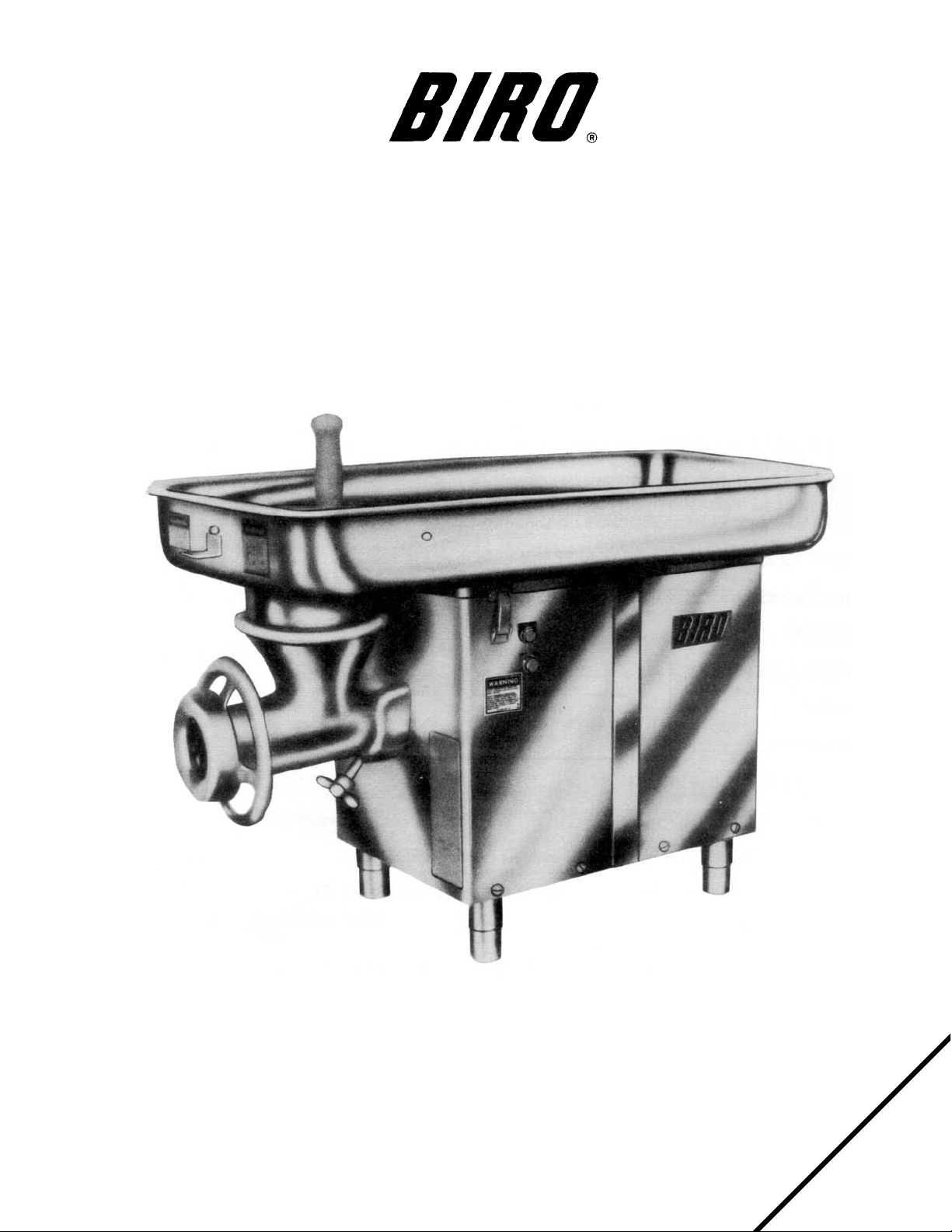
BIRO GRINDER PARTS LIST
STAINLESS MODEL 6642
047-7-07-27
Page 2

TABLE OF CONTENTS
Page
NOTICETOOWNERSANDOPERATORS......................................... 1
SAFETYTIPS............................................................... 2
INSTALLATION ............................................................. 3
UNCRATINGANDSETUP ................................................... 3
MOTOR WIRING AND ELECTRICAL REQUIREMENTS . . . . . . . . . . . . . . . . . . . . . . . . . . . . . . 4
MOTORSPECIFICATIONS................................................... 5
WARNINGLABELSANDLOCATIONSONGRINDER................................. 5
PARTS DIAGRAMS, PARTS ORDERING BASIC MACHINE . . . . . . . . . . . . . . . . . . . . . . . . . . . . . 6
INSTRUCTIONS: REMOVINGTRAYASSEMBLY.................................... 7
INSTRUCTIONS: ASSEMBLING GRINDING BOWL, REMOVING GRINDING BOWL . . . . . . . . . 7
OPERATION................................................................ 8
TOPROCESSPRODUCT.................................................... 8
CLEANING................................................................. 9
MAINTENANCE .............................................................10
GRINDINGBOWLINSTALLATION.............................................10
GEARBOXLUBRICATION...................................................10
GEAR BOX ASSEMBLY PARTS DIAGRAMS AND PARTS ORDERING. . . . . . . . . . . . . . . . . . . . . 11
MAGNETIC SWITCH SYSTEMS PARTS DIAGRAMS AND PARTS ORDERING . . . . . . . . . . . . . . 12
WIRINGDIAGRAMS ..........................................................13
PARTS LISTS/ORDERING FOR GRINDERS PRIOR TO SERIAL NO. 9340 . . . . . . . . . . . . . . . . . 14
OPERATOR'SSIGNATUREPAGE................................................15
LIMITEDWARRANTY.........................................................16
Page 3
BIRO’s products are designed to process food products safely and efficiently. Unless the operator is properly trained and supervised, however, there is the possibility of a serious injury. It is the
responsibility of the owner to assure that this machine is used properly and safely, strictly following
the instructions contained in this Manual and any requirements of local law.
No one should use or service this machine without proper training and supervision. All operators should be thoroughly familiar with the procedures contained in this Manual. Even so BIRO
cannot anticipate every circumstance or environment in which its products will be used. You, the
owner and operator, must remain alert to the hazards posed by the function of this equipment –
particularly the ROTATING GRINDING WORM, which can severely injure an inattentive operator
amputating fingers and limbs. No one under eighteen (18) years of age should operate this equipment. If you are uncertain about a particular task, ask your supervisor.
This Manual contains a number of safe practices in the SAFETY TIP section. Additional warnings are placed throughout the Manual. Warnings related to your personal safety are indicated by:
Warnings related to possible damage to the equipment are indicated by:
BIRO also has provided warning labels on the equipment. If any warning label or Manual becomes misplaced, damaged, or illegible, please contact your nearest Distributor or BIRO directly
for a replacement.
Remember, however, this Manual or the warning labels do not replace the need to be alert and
to use your common sense when using this equipment.
This Manual applies to machines with Serial Number 2321 and higher.
1
NOTICE TO OWNERS AND OPERATORS
OR
- NOTE -
“A copy of this manual is included with each Model 6642 Grinder”
“The descriptions and illustrations contained in this manual
are not binding. The manufacturer reserves the right to
introduce any modification without updating the manual.”
Page 4

SAFETY TIPS
ROTATING GRINDING WORM
TO AVOID SERIOUS PERSONAL INJURY
NEVER Touch This Machine Without Training and Authorization By Your Supervisor.
NEVER Place Hands Into Machine Input or Output Openings.
NEVER Open Machine During Operation.
ONLY Use a Qualified Electrician to Install According to Local Building Codes: Machine MUST
Be Properly Grounded.
ALWAYS Connect to Proper Voltage & Phase.
ONLY Install on Level, Non-Skid Surface in a Clean, Well-Lighted Work Area Away From
Children and Visitors.
NEVER Use This Machine For Non-Food Products.
NEVER Operate Machine With Tray And/Or TrayGuard Removed or Magnetic Safety Swtich
By-Passed.
ALWAYS Turn Off, Unplug From Power Source and Perform Lockout/Tagout Procedure to This
Machine BEFORE Attempting to Unjam or Unclog, Cleaning or Servicing.
NEVER Leave Machine Unattended While Operating.
NEVER Alter This Machine From its Original Form as Shipped From Factory. DO NOT Operate
Machine With Parts Missing.
PROMPTLY REPLACE Any Worn or Illegible Warning Labels.
ALWAYS Read Operation and Service Manual BEFORE Operating, Cleaning or Servicing.
USE ONLY BIRO Parts and Accessories Properly Installed.
2
Page 5

INSTALLATION
TO AVOID SERIOUS PERSONAL INJURY
PROPERLY INSTALL EQUIPMENT IN ADEQUATE WORK AREA
ALWAYS Use Qualified Technician and Electrician for Installation.
ALWAYS Connect to Proper Voltage & Phase.
ALWAYS Install Equipment in Work Area with Adequate Light and Space Away From Children
and Visitors.
ONLY Operate on a Solid, Level, Non-Skid Surface.
NEVER Bypass, Alter, or Modify This Equipment in Any Way From Its Original Condition.
NEVER Operate With Tray And/Or Tray Guard Removed or Magnetic Safety Switch By-Passed.
NEVER Operate Without all Warning Labels Attached and Owner/Operator Manual Available to
the Operator.
UNCRATING AND SET UP
1. Read this Manual thoroughly before installation and operation. Do not proceed with installation and operation if
you have any questions or do not understand anything in this Manual. Contact your local Distributor, or BIRO
first.
2. Install machine on a level, solid, non-skid surface in a well-lighted work area away from children and visitors.
3. After installing machine in operational area, it is imperative that the four adjusting legs be adjusted to level the
machine and also eliminate rocking.
4. This machine is complete except for a knife and plate. There is a bowl shipping plug (stamped steel) placed in
the output end of the grinding bowl to retain the grinding worm during shipment. REMOVE THE BOWL
SHIPPING PLUG AND THE GRINDING WORM.
5. After checking and making sure the power supply is correct, plug in your machine. NEVER OPERATE
MACHINE WITHOUT TRAY AND GUARD INSTALLED. (Machine will not run with tray removed.)
3
ALWAYS LEVEL MACHINE BEFORE USING
Page 6

6. Machine must be properly grounded. Use qualified electrician to install according to building codes.
MOTOR WIRING AND ELECTRICAL REQUIREMENTS
(A) Interchange of current is made in motor outlet box. Leads are properly marked. Changing instructions are
on the motor plate or motor outlet box.
(B) All grinders are wired 220 volts unless otherwise specified. Be sure motor specifications (voltage, cycle,
phase) match power supply line. Be sure line voltage is up to specification.
(C) Electrical connections to be in accordance with safety codes and National Electrical Code.
(D) Rated voltage of the unit shall be identical with full supply voltage.
(E) Voltage drop on the supply line shall not exceed 10% of full supply voltage.
(F) The feederline conductor size in the raceway from the branch circuit to the unit must be correct to assure
adequate voltage under heavy starting and short overload conditions.
(G) The feederline conductor shall only be used for the supply of one unit of the relevant horsepower. For
connections of more than one unit on the same feederline, a local electrician will have to be consulted to
determine the proper conductor size.
(H) The size of the electrical wiring required from the power source to the grinder for 208/220/230/440/550 Volts
is a MINIMUM of No. 12 AWG. For 110/115 Volts is a MINIMUM of No. 10 AWG.
(I) The BIRO Manufacturing Company is not responsible for permanent wiring, connection or installation.
MOTOR
HP VOLTS HZ PH AMPS
2 104 60 1 31
2 115 60 1 28
2 208 60 1 15.5
2 230 60 1 14
2 208 dedicated 60 3 5.0
2 208/220 50/60 3 6.2/6.0
2 440 50/60 3 3.0
2 550 60 3 2.24
4
NOTE TO OWNER AND ELECTRICIAN: IF THIS MACHINE IS NOT CORD
AND PLUG CONNECTED TO THE ELECTRICAL SUPPLY SOURCE, THEN IT
SHOULD BE EQUIPPED WITH, OR CONNECTED TO, A LOCKABLE,
MANUALLY-OPERATED DISCONNECT SWITCH (OSHA 1010.147).
Page 7

7. Pushbuttons that activate the internal on/off switch are located on the side of the machine. The interlock safety
switch is mounted inside the machine case toward the front and will break contact with the magnetic starter
should the tray be removed.
8. Push the green “ON” button. CHECK THE ROTATION OF THE WORM DRIVE SHAFT. ROTATION MUST
BE COUNTER-CLOCKWISE as indicated by the rotation decal affixed to the grinding bowl. ROTATION MUST
ONLY BE CHECKED WITH THE GRINDING WORM REMOVED, otherwise serious irreparable damage may
occur to grinding components. Push red “STOP” button.
9. If machine runs clockwise (backwards), it must be rewired to correct rotation, otherwise serious irreparable
damage may occur to grinding components.
10. Insert worm assembly into grinding bowl, place knife (sharp edges out) onto the square end of the worm
assembly. The breaker plate slides over the worm knife drive pin, and is held from rotating by pins in the grinding
bowl. Install on the retaining ring.
ONLY HAND TIGHTEN RETAINING RING
For best results, use knife and plate as a set. Do not operate machine for any period of time without product
in the grinding bowl. This will cause heating and dulling of the knife and plate.
11. Check placement of all warning labels and Manual. Machine is now ready for trained operators to process
product.
12. Use meat deflector attached to tray to eliminate meat splatter.
13. Contact your local Distributor or BIRO directly if you have any questions or problems with the installation or
operation of this machine.
WARNING LABELS & LOCATIONS ON GRINDER
5
Page 8

Page 9

7
TO REMOVE TRAY ASSEMBLY
1. Unplug grinder from power source, perform
lockout/tagout procedures.
2. Unlock Tray Hold Down Latches.
3. Lift front of tray enough for magnet to clear the
case top, slide Tray Assembly toward back of
grinder and lift off.
TO ASSEMBLE BOWL
1. Make certain the Bowl Lock Screw is unscrewed
sufficiently to alllow free entry of Grinding Bowl.
2. With End Retaining Ring, Knife, Breaker Plate and
Grinding Worm removed, insert the Grinding
Bowl fully into the gear box housing, making sure
that the rear end of the Grinding Bowl is flush with
the gear box housing.
3. Tighten the Bowl Lock Screw.
4. Insert the Grinding Worm and fully seat square
drive.
5. Install the Knife (sharp side out) and Breaker
Plate.
6. Install End Retaining Ring.
HAND TIGHTEN ONLY.
TO REMOVE GRINDING BOWL
1. Unplug grinder from power source, perform
lockout/tagout procedures.
2. Remove End Retaining Ring, Knife, Breaker Plate,
and Grinding Worm.
3. Loosen Bowl Lock Screw (counterclockwise).
4. Remove Grinding Bowl.
MOTORS FOR MODEL 6642 GRINDER
Item No. Description
42MC-10-4U Motor, 2HP, 550-60-3, U.S. G57892
42MC-10-5U Motor, 2HP, 104/208-60-1, U.S.
G57328
42MC-10-6U Motor, 2HP, 115/230-60-1, U.S.
G54314
42MC-10-7U Motor, 2HP, 208/230/460-50/60-3,
U.S. 57893
42MC-10-8U Motor, 2HP, 115/230-50-1, U.S.
G57901
42MC-10-9U Motor, 2HP, 208-60-3, U.S. G57890
Page 10

OPERATION
ROTATING GRINDING WORM
TO AVOID SERIOUS PERSONAL INJURY
ONLY Properly Trained Personnel Should Use This Equipment.
NEVER Place Hands Into Machine Input or Output Openings.
NEVER Open Machine During Operation.
DO NOT Wear Gloves While Operating.
DO NOT Tamper With, Bypass, Alter, or Modify This Equipment in Any Way From Its Original
Condition.
NEVER Operate Machine With Tray And/Or Tray Guard Removed or Magnetic Safety Switch
By-Passed.
ALWAYS Turn Off, Unplug From Power Source and Perform Lockout/Tagout Procedure to This
Machine Before Unjamming, Unclogging, Cleaning or Servicing.
NEVER Leave Unattended While Operating.
NEVER Operate Without All Warning Labels Attached and Owner/Operator Manual Available to
the Operator.
A. TO PROCESS PRODUCT
1. Before starting grinder, have meat stomper within easy reach and a container for receiving ground product at
the output end of grinding bowl.
2. Push the green “ON” button. Look down grinder bowl and make certain grinding worm is turning in the
proper direction (counter-clockwise).
3. Carefully push unground product to top opening of grinding bowl and let drop onto the grinding worm.
Product will then be ground out.
DO NOT REACH DOWN BOWL OPENING
4. Use meat stomper to assist any product that should “bridge up” in grinding bowl opening.
5. When finished grinding, push the red “OFF” position and unplug grinder from power source and perform
lockout/tagout procedures.
8
Page 11

CLEANING
ROTATING GRINDING WORM
TO AVOID PERSONAL INJURY
ALWAYS Turn Off, Unplug From Power Source and Perform Lockout/Tagout Procedure to This
Machine BEFORE Cleaning or Servicing.
ONLY Use Recommended Cleaning Equipment, Materials and Procedures.
NEVER Spray Water or Other Liquid Substances Directly at Motor, Power Switch or any Other
Electrical Components.
ALWAYS Thoroughly Clean Equipment at Least Daily.
CLEANING THE BIRO MODEL 6642 GRINDER
1. Disconnect grinder from power source and perform lockout/tagout procedures.
2. Remove the feed tray.
3. Remove grinding bowl end ring, breaker plate, knife and grinding worm and the grinding bowl.
DO NOT SPRAY DIRECTLY AT ELECTRICAL COMPONENTS
4. Machine is now ready to be cleaned using warm soapy water and rinsed with clean water. Machine may be
cleaned by power spray washing, taking care to not spray directly at any electrical controls.
5. After machine has been cleaned and allowed to dry, all exposed metal surfaces should be coated with a good
food grade light oil or grease.
9
DO’s
•
Always keep knife & plate as matched set.
•
Always keep the knife & plate sharp.
•
Always check for levelness by laying the knife on the
plate before inserting in machine.
• Always install the knife & plate in correct sequence,
knife 1st, then plate.
• Always keep knives & plates lubricated in storage and
when starting up machine.
• Always use coolant when sharpening plates.
• Always inspect the plates making sure all holes are
clear – that there are no cracks.
DON’Ts
•
Never, never mix different knives to different plates.
•
Never, never over tighten the bowl retaining ring on
the machine.
•
Never, never run the grinder/mincer without product.
Product is a natural lubricant. Heat can build up so
fast that cold product could crack the plate.
• Never, never hit the plate against anything to clean
the holes.
• Never, never throw the knives & plates.
Page 12

10
MAINTENANCE
ROTATING GRINDING WORM
TO AVOID SERIOUS PERSONAL INJURY
ALWAYS Turn Off, Unplug From Power Source and Perform Lockout/Tagout Procedure to This
Machine BEFORE Servicing.
NEVER Touch This Machine Without Training and Authorization By Your Supervisor.
NEVER Place Hands Into Machine Input or Output Openings.
NEVER Bypass, Alter, or Modify This Equipment in Any Way From Its Original Condition.
PROMPTLY REPLACE Any Worn or Illegible Labels.
USE ONLY GENUINE BIRO Parts and Accessories Properly Installed.
A. GRINDING BOWL INSTALLATION
1. Mount the grinding bowl in the gear box opening. Insert screw lock under the grinding bowl and hand
tighten fully seating the bowl.
2. Place the grinding worm in the grinding bowl and fully seat rear drive tang into worm drive shaft.
3. Install knife, breaker plate and end retaining ring.
ONLY HAND TIGHTEN RETAINING RING
4. When the bowl assembly is mounted and tight, there should be approximately
1
8
" gap between the back
inside wall of the bowl and the back of the worm. The bowl ring wrench which is provided with each grinder
is used only for REMOVAL of the end retaining ring for cleaning purposes or for changing knife and breaker
plate.
B. GEAR BOX LUBRICATION
1. The gear box lubricant should be changed after the first four (4) weeks of operation to remove any metal
particles that may be generated during the initial mating of the gears.
2. Thereafter at one (1) year intervals.
3. There is a drain plug on the underside of the gear box.
4. Refill with a measured one (1) pint of LUBRIPLATE #APG-140 gear oil or equivalent.
CLEANING THE BOWL - RING AND WORM
CARE OF TIN COATED PRODUCTS
(DO’S AND DON’TS)
1. Do not use abrasive cleaning materials, such as brillo pads or metal scrapers. Tin is a soft metal and should be cleaned with a
soft cloth and dried.
2. Do not use a cleaning agent containing a high percentage of free alkali or acid.
3. Do not use a detergent containing a high percentage of tri-sodium phosphate or meta-silicate. Tin is reactive to both.
4. Rinse well and dry throughly after washing to remove agents that may be reactive to tin.
5. If sterilizing agent containing chlorine is used, the tinned surface must be throughly rinsed. Chlorine is corrosive to tin.
6. Dry throughly after rinsing and store in a dry environment.
7. If water is exceptionally hard, drying will be necessary to prevent spotting.
Page 13

MODEL 6642 GEAR BOX ASSEMBLY
PARTS LIST
11
Item No. Description
FW12S Flat washer,
3
8
,SS
HHS045 Hex head screw,
1
4
-20
´
7
8
HHS070S Hex head screw,
3
8
-16´1, SS
LW10 Lock washer,
1
4
LW25S Lock washer,
3
8
,SS
LW30 Lock washer,
1
2
MC-1Z Gear box only
MC-10D Motor shaft slottet nut
MC-10E Cotter key,
1
8
´
1
MC-105 Motor seal, lip type
MC-11Z Lower shaft washer
MC-12 Gear box motor bolt, short
MC-12A Gear box motor bolt, long
MC-13Z Lower shaft bearing adj. cap
MC-2BL Bowl locator pin, dowel
MC26ZAZ Idler bearing cup/cone
MC-27ZAZ Rear thrust bearing cup/cone
MC-29 Upper shaft oil seal
MC-30A Uper brg. cap set screw, long
MC-31 Adjusting cup & seal housing
MC-34 Woodruff gear key, #91
MC-35 Gear box cover locator pin
MC-39 Oil plug,
1
8
´
3
8
MC-40 NPT vented plug,
1
8
Item No. Description
MC-5Z1 Upper shaft spacer
MC-51L Gear box lubricant, 1 pint
MC-6A Motor pinion gear
MC-7A Idler gear
MC-8 Idler pinion gear
MC-9 Drive gear
SSS13 Set screw,
1
4
-20
´
3
8
300 Lower shaft woodruff key
42MC-110 Gear box O-ring seal, #8493 on
42MC-115 Gear box cover gasket
42MC-2R Gear box cover only, #2321 on
42MC-2R1 Heli-coil insert, SS, #3663 on
42MC-3Z Up. shaft, hollow sq. end, #2321 on
42MC-4Z Lower shaft
ASSEMBLIES FOR GEAR BOX
Item No. Description
A227 Upper bearing cup/cone assembly
B42MC-2R Gear box cover assembly, #2321 on
BMC-1Z-1 Gear box assembly, #2321 on
w/motor seal
BMC-Y21R-3 Bowl lock assembly, #2321 on
MC-26ZAZ Idler bearing cup/cone assembly
MC-27ZAZ Rear thrust bearing cup/cone
assembly
Page 14

MODEL 6642 MAGNETIC SWITCH SYSTEM
WITH SAFETY INTERLOCK SWITCH STARTING WITH SERIAL NO. 9340
CONTACTOR COIL VOLTAGE MUST BE SAME AS POWER SUPPLY VOLTAGE
12
Item No. Description
42MC-Y20-8 Magnet, S/N 5796 to 8150
42MC-Y60 Safety interlock switch bracket, S/N
5796 to 8151
42MC-AE79K AEG contactor, 2HP, 1 & 3PH
(208/220/230V), 50/60Hz with din
rail, fasteners and clips
42MC-AE80K AEG contactor, 2HP, 3PH, (440V),
60Hz with din rail, fasteners, and clips
42MC-AE81K AEG contactor, 2HP, 3PH (380-415V)
50Hz with din rail, fasteners and clips
Item No. Description
42MC-AE82K AEG contactor, 2HP, 3PH (550V)
60Hz with din rail, fasteners and clips
42MC-AE84K AEG contactor, 2HP, 1PH (110/120V)
60Hz with din rail, fasteners and clips
6808-G Toggle Switch (1PH) to S/N 5796
7810-G Toggle Switch (3PH) to S/N 5796
800S-2ASQ GP Push button station – flush
mount, S/N 5796 to 9339
Item No. Description
42MC-Y20-8A Magnet S/N 8151 on
42MC-Y64 Magnet safety interlock switch,
SN5796 on (up to 250V)
H442-1 Magnetic safety interlock switch
(250V and up)
42MC-Y67 Flange spade crimp-on connector
42MC-Y70 Safety switch bracket
42MC-Y73 Green start button
42MC-Y74 Red stop button
42MC-Y75 “Start” legend plate
42MC-Y76 “Stop” legend plate
42MC-Y77 Switch hole cap plug
42MC-AE79 AEG contactor, 2HP, 1 & 3PH,
(208/220/230V), 50/60Hz
42MC-AE79A AEG contactor & overload 2HP, 1 &
3 PH (208/230V) 50/60Hz
Item No. Description
42MC-AE79-CL Coil, 220V
42MC-AE0L08L AEG overload 2HP, 1 & 3PH
(208/230V) 5.6-8 amp
42MC-AE80 AEG contactor, 2HP, 3PH (440V), 60Hz
42MC-AE81 AEG contactor, 2HP, 3PH,
(380/415V) 50Hz
42MC-AE82 AEG contactor, 2HP, 3PH, (550V) 60Hz
42MC-AE83 AEG contactor 2HP, 3PH (24V)
50/60Hz
42MC-AE84 AEG contactor, 2HP, 1PH,
(110/120V) 60Hz
42MC-AE87 3.5" long din rail
BLK323 End barrier
HHS010S Hex head screw, 10-32
´
3
8
"SS
HN10S Hex nut, 10-32 SS
Item No. Description
42MC-Y20-8A Magnet S/N 8151 on
42MC-Y64 Magnet safety interlock switch,
H442-1 Magnetic safety interlock switch
42MC-Y67 Flange spade crimp-on connector
42MC-Y70 Safety switch bracket
42MC-Y73 Green start button
42MC-Y74 Red stop button
42MC-Y75 “Start” legend plate
42MC-Y76 “Stop” legend plate
42MC-Y77 Switch hole cap plug
226EE-CO11K AEG contactor, 2HP, 1 & 3PH,
42MC-EE79A AEG contactor & overload 2HP, 1 &
SN5796 on (up to 250V)
(250V and up)
(208/220/230V), 50/60Hz
3 PH (208/230V) 50/60Hz
Item No. Description
42MC-Y20-8 Magnet, S/N 5796 to 8150
42MC-Y60 S
42MC-EE79K AEG contactor, 2HP, 1 & 3PH
42MC-EE80K AEG contactor, 2HP, 3PH, (440V),
42MC-EE81K AEG contactor, 2HP, 3PH (380-415V )
afety interlock switch bracket, S/N
5796 to 8151
(208/220/230V), 50/60Hz with din
rail, fasteners and clips
60Hz with din rail, fasteners, and clips
50Hz with din rail, fasteners and clips
Item No. Description
42MC-AE79-CL Coil, 220V
226EE-0L08.5L AEG overload 2HP, 1 & 3PH
226EE-EO11K AEG contactor, 2HP, 3PH (440V), 60Hz
226EE-EO11K AEG contactor, 2HP, 3PH, same/coil
226EE-FO11K AEG contactor, 2HP, 3PH, (550V) 60Hz
226EE-GO11K AEG contactor 2HP, 3PH (24V)
226EE-AO15K AEG contactor, 2HP, 1PH,
42MC-AE87 3.5" long din rail
BLK323 End barrier
HHS010S Hex head screw, 10-32 3/8" SS
HN10S Hex nut, 10-32 SS
(208/230V) 5.5-8.5 amp
rated 400V (380/415V) 50Hz
50/60Hz
(110/120V) 60Hz
Item No
42MC-EE82K AEG contactor, 2HP, 3PH (550V)
42MC-EE84K AEG contactor, 2HP, 1PH (110/120V )
6808-G Toggle Switch (1PH) to S/N 5796
7810-G Toggle Switch (3PH) to S/N 5796
800S-2ASQ GP Push button station – flush
. Description
60Hz with din rail, fasteners and clips
60Hz with din rail, fasteners and clips
mount, S/N 5796 to 9339
Page 15

Page 16

IMPORTANT:
PLEASE SPECIFY SERIAL NUMBER WHEN
ORDERING REPLACEMENT PARTS.
PARTS LIST SPECIFIC TO MACHINES PRIOR TO SERIAL NO. 9340
Item No. Description
M99-2-17 Sta. switch, 2HP, 50Hz, Baldor mtr.
M99-2-17A Rot. switch, 2HP, 500/60Hz Baldor
mtr.
MC-100 Motor seal, ORDER MC105
MC-25B Model plate switch slot
MC-25B1 Name plate self-tap screw
MC-25C Model plate case screw
MC-25D Sw. to model plate screw 6-32
´
3
8
42MC-Y25B Case, SS, 18 inch, #5796 to #8150
42MC-Y25B5 Adapter plate, sw. to new case
42MC-Y49-1 Drive screw for ali. guard, #14
´
5
8
42MC-49SFT Tray guard, ali, #4800 to #8272
Item No. Description
BMC-Y21R-1 Bowl lock assembly,
1
2
", to #3663
B42MC-L20 Large tray w/guard safety kit, to
#2000
B42MC-Y20A-OS
Tray w/guard & safety kit, #2000 to
#4799
B42MC-Y20A1 Tray assembly w/guard & magnet
#5796 to #8151
B42MC-Y25C SS case assembly w/model plate and
decals, #8151 to #9339
B42MC-Y25E SS case assembly, 18 inch, #4800 to
#5795
B42MC-Y25F SS case assembly, 18 inch, #2000 to
#4800
Page 17

OPERATOR’S SIGNATURE PAGE
MY SIGNATURE ATTESTS THAT I HAVE COMPLETELY READ AND UNDERSTAND THIS
MANUAL. I REALIZE THAT THIS MACHINE, IF OPERATED CARELESSLY, CAN CAUSE SERIOUS INJURY TO MYSELF AND OTHERS.
NAME (PRINT) SIGNATURE
SUPERVISOR’S
INITIALS
DATE
Page 18

LIMITED WARRANTY
WARRANTY: The BIRO Manufacturing Company warrants that the BIRO Model 6642 Grinder will
be free from defects in material and workmanship under normal use and with recommended service. BIRO will replace defective parts, which are covered by this limited warranty, provided that
the defective parts are authorized for return, shipping charges prepaid, to a designated factory for
inspection and/or testing.
DURATION OF WARRANTY: The warranty period for all parts covered by this limited warranty is
one (1) year from date of inspection/demonstration as advised on the returned warranty registration card, or eighteen (18) months from original factory shipping date, whichever date occurs first,
except as noted below.
PARTS NOT COVERED BY WARRANTY: The following are not covered by this limited warranty:
wearable parts in the grinding system such as bowl, worm drive shaft, ring, worm, and knife drive
pin. This limited warranty does not apply to machines sold as used, rebuilt, modified, or altered
from the original construction in which the machine was shipped from the factory. Water contaminated electrical components are not covered under this limited warranty. BIRO is not responsible
for electrical connection of equipment, adjustments to switch components or any other electrical
requirements, which must be performed only by a certified electrician. BIRO is not responsible for
service charges or labor required to replace any part covered by this limited warranty or for any
damages resulting from misuse, abuse, lack of proper or recommended service.
EXCLUSION OF WARRANTIES AND LIMITATION OF REMEDIES: BIRO gives no warranties
other than those expressly stated in this limited warranty. THE IMPLIED WARRANTY OF MERCHANTABILITY, THE IMPLIED WARRANTY OF FITNESS FOR PROCESSING OF FOOD PRODUCTS, AND ALL OTHER IMPLIED WARRANTIES ARE SPECIFICALLY EXCLUDED. BIRO IS NOT
LIABLE FOR CONSEQUENTIAL OR INCIDENTAL DAMAGES, EXPENSES, OR LOSSES. THE
REMEDIES PROVIDED IN THIS BIRO LIMITED WARRANTY ARE PURCHASER’S SOLE AND EXCLUSIVE REMEDIES AGAINST BIRO.
REGISTRATION CARDS: You must sign, date and complete the warranty registration card supplied with each machine. The warranty registration card must be returned to The Biro Manufacturing Company for proper registration. If no warranty registration card is returned to BIRO, the
warranty period will begin from the date the machine was originally shipped from the factory.
HOW TO GET SERVICE:
1. Contact the agency from whom you purchased the machine; or
2. Consult the yellow pages of the phone directory for the nearest authorized dealer; or
3. Contact Biro Mfg. Company for the nearest authorized service entity (250 plus worldwide) in
your area.
THE BIRO MANUFACTURING COMPANY
1114 Main Street
Marblehead, Ohio 43440-2099
Ph. 419-798-4451
Fax 419-798-9106
E-mail: service@birosaw.com
Web: http://www.birosaw.com
16
ITEM NUMBER 42MC-Y53-047
PTCT 6642-047-11-04-25 COMM.
ITEM NO. 42MC-Y53-047
PTCT 6642-047 7-07-27 ACME
 Loading...