

Page 1
PT-E05
Jp
En
Fr
De
Sp
Cs
Kr
取扱説明書
デジタルカメラ用防水プロテクター
Instruction Manual
Underwater Case for digital camera
Mode d’emploi
Caisson étanche pour l’appareil photo numérique
Bedienungsanleitung
Unterwassergehäuse für Digitalkamera
Manual de instrucciones
Caja estanca para la cámara digital
Page 2

このたびは、防水プロテクター PT-E05をお買上げいただき、ありがとうございます。
この説明書をよくお読みのうえ、安全に正しくお使いください。また、この説明書はお読みになっ
た後、必ず保管してください。
誤った使い方をされると水漏れにより中のカメラが破損し、修理不能になる場合があります。
ご使用前には、この説明書にしたがい、必ず事前チェックを実施してください。
はじめに
z 本書の内容の一部または全部を無断で複写することは、個人としてご利用になる場合を除き禁止さ
れています。また、無断転載は固くお断りいたします。
z 本製品の不適切な使用により、万が一、損害が発生した場合、逸失利益に関し、または、第三者か
らのいかなる請求に対し、当社では一切その責任を負いかねますのでご了承ください。
z 本製品の故障、当社指定の第三者による分解、修理、改造その他の理由により生じた画像データの
消失による損害および逸失利益などに関し、当社では一切その責任を負いかねますのでご了承くだ
さい。
ご使用の前に必ずお読みください
z このプロテクターは、水深40m以内の水中で使用するよう設計された精密機械です。取り扱いには
十分ご注意ください。
z プロテクターのご使用前の取り扱い方法と事前チェック、メンテナンス、ご使用後の保管方法はこ
の取扱説明書の内容をよくご理解のうえ、正しくご利用ください。
z プロテクターご使用の際は、必ず別売の防水ポートと組み合わせてご使用いただく必要があります。
ご注意ください。
z デジタルカメラの水没事故は、当社では一切その責任を負いかねます。また、水没による内部機材
の損傷、記録内容や撮影に要した諸費用などの保証はいたしかねます。
z 使用時の事故(人身・物損)の補償はいたしかねます。
Jp
安全にお使いいただくために
この取扱説明書では、製品を正しくお使いいただき、お客様や他の人々への危害と財産の損害を未然
に防止するために、いろいろな絵表示をしています。その表示と意味は次のようになっています。
警告
注意
JP 1
この表示を無視して誤った取り扱いをすると、人が死亡または重傷を負う可能性
が想定される内容を示しています。
この表示を無視して誤った取り扱いをすると、人が傷害を負う可能性が想定され
る内容および物的損害のみの発生が想定される内容を示しています。
Page 3

警告
1 本製品を乳児、幼児、子供の手の届く範囲に放置しないでください。以下のような事故発生の可能性
があります。
• 高いところから身体の上に落下し、けがをする。
• 開閉部に身体の一部をはさみけがをする。
• 小さな部品を飲み込む。万が一飲み込んだ場合は直ちに医師にご相談ください。
2 本製品に装填されるデジタルカメラに電池を入れたまま保管しないでください。
電池を入れたまま保管すると、液漏れや火災の原因となることがあります。
3 本製品をご使用の際は、必ず別売の防水ポートを組み合わせてご使用ください。本製品単独ではご使
用できません。
4 万が一、本製品にカメラを装填した状態で水漏れがあった場合は、カメラに装填された電池を速やか
に抜いてください。水素ガスの発生による燃焼•爆発の可能性があります。
5 本製品は樹脂製です。岩などの固いものに強くぶつけると破損し、けがをする可能性があります。取
り扱いには十分ご注意ください。
6 本製品用のシリカゲルおよびシリコングリスは食べられません。
注意
1 本製品の分解、改造はしないでください。水漏れや不具合発生の原因となることがあります。当社指
定者以外の者による分解、改造をした場合は保証の対象外となります。
2 異常に温度が高くなるところ、異常に温度が低くなるところ、極端な温度変化のあるところに本品を
置かないでください。部品が劣化することがあります。
3 砂、ほこり、塵の多いところで開閉すると防水性能が損なわれ水漏れの原因となることがあります。
絶対に避けてください。
4 本製品は水深40m以内の水深で使用するように設計•製造されています。40mより深い潜水をされた場
合、本プロテクターや中のカメラに復帰しない変形や破損が生じたり、水漏れを起こすことがありま
す。ご注意ください。
5 プロテクターをポケットに入れたまま、あるいは、持ったまま水中に勢いよく飛び込んだ場合や船上
から海へ放り投げる等、乱暴に扱うと水漏れする場合があります。手渡しをする等、取り扱いには十
分ご注意ください。
6 万が一、水漏れ等で内部のカメラが濡れた場合は直ちにカメラの水分を拭き取り、動作確認をしてく
ださい。
7 飛行機で移動する場合は、O リングを取りはずしてください。気圧の関係でプロテクターが開かなく
なることがあります。
8 本製品に装填されるデジタルカメラを安全にお使いいただくために、デジタルカメラの取扱説明書を
よくお読みください。
9 本製品を密閉する際はOリングおよびその接触面に異物を挟み込まないように十分ご注意ください。
0 本製品とオリンパス製フラッシュを組み合わせて使用する場合、カメラのホットシュー部にホット
シューケーブルを装着した状態では、カメラの内蔵フラッシュをポップアップできません。無理にポッ
プアップした場合、フラッシュが正常に動作せず、また、カメラのホットシュー部に装着したホット
シューケーブルがはずれる場合があります。また、デジタルカメラの破損の原因となりますので十分
ご注意ください。
a 本製品では、カメラの内蔵フラッシュ光での撮影はできません。
Jp
JP 2
Page 4
Jp
電池について
z カメラ専用の当社リチウムイオン充電池(BLM-1)1個をご使用ください。
z 電池の電極を濡らさないようご注意ください。故障や、事故の原因となる可能性があります。
z 電池に関するその他の注意はカメラの取扱説明書をよくお読みください。
水漏れ事故を防ぐために
本製品を使用中に水漏れ事故が発生すると装填されたデジタルカメラが修理不能になります。以下の
注意を守った上でご使用ください。
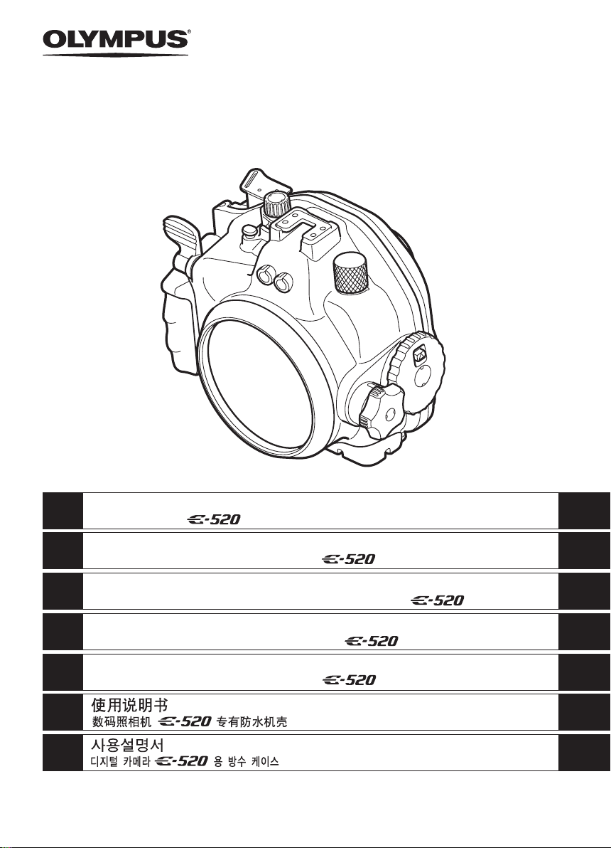
1 本製品を密閉する際にはO リングだけではなくその接触面にも髪の毛、繊維くず、砂粒等の異物がつ
いていないことを確認してください。たとえ髪の毛一本、砂粒一粒が挟まっても水漏れの原因となり
ます。特に念入りに確認してください。
Oリングへの異物付着の一例
髪の毛 繊維屑 砂粒
2 Oリングは消耗品です。少なくとも1年に1回は新品と交換してください。また、ご使用の都度メンテ
ナンスをしてください。
3 Oリングは使用状態、保管状態によっては劣化が促進されます。Oリングに傷、ヒビが入っていたり、
弾力がなくなっていたらすぐに新しいOリングに交換してください。
4 Oリングメンテナンス時にはOリング溝内をクリーニングし、ゴミ・ほこり・砂粒等の異物がないこ
とを確認してください。
5 Oリングには指定のシリコングリスをご使用ください。
6 Oリングが正しく入っていないと防水機能が働きません。Oリングを装着する際にはOリングが溝か
らはみ出したり、ねじれたりしないよう注意して取り付けてください。また、プロテクターを密閉す
るときはOリングが溝からはずれないよう確認しながら蓋を閉めてください。
7 本製品はプラスティック(ポリカーボネート)製の気密構造です。車、船、海辺など高温になるとこ
ろに長時間放置したり、長時間不均一な外力がかかると変形し、防水機能が失われることがあります。
温度管理には十分ご注意ください。また、保管時や移動時に上に重いものを載せたり、無理な収納は
避けてください。
8 プロテクターの外側からO リングの接触面を強く押したり、プロテクターをねじったりすると防水機
能が損なわれることがあります。無理な力をかけないようご注意ください。
9 事前テストと最終チェックを実施した上でご使用ください。
0 撮影中に水滴、曇りなど水漏れの兆候を見つけた場合は、直ちに潜水を中止して、カメラおよび本製
品の水気を取り、「最終チェックをします」の項目を参考にしてテストを行い水漏れの有無を確認して
ください。
JP 3
Page 5

お取り扱いについて
z 以下のような場所で本製品を使用または保管した場合、動作不良や故障、破損、火災、内部の曇り、
水漏れの原因となります。絶対に避けてください。
• 直射日光下や自動車の中など高温になるような場所
• 火気のある場所
• 水深40mより深い水中
• 振動のある場所
• 高温多湿や温度変化の激しい場所
• 揮発性物質のある場所
z 本製品は耐衝撃性に優れたポリカーボネート樹脂製ですが、岩などで擦ると傷が付くことがありま
す。また、固い物にぶつけたり、落としたりすると破損することがあります。
z 本製品は装填されたカメラへの衝撃をやわらげるケースではありません。本製品にデジタルカメラ
を装填した状態で衝撃を与えたり、重いものを載せたりするとデジタルカメラが故障する場合があ
ります。取り扱いには十分ご注意ください。
z 長期間使用しないとO リングの劣化等により防水性能が低下している場合があります。使用前には
事前テストと最終チェックを必ず行ってください。
z ポート取り付け部、TTL ケーブルコネクタ部、ズームダイヤル部、三脚座等には過大な力をかけな
いでください。
z ガス抜き弁を内側から押さないでください。
z 洗浄・防錆・防曇・補修等の目的で、下記の薬品類を使わないでください。プロテクターに直接、
あるいは、間接的(薬剤が気化した状態)に使用した場合、高圧下でのひび割れなどの原因となり
ます。
使用できない薬品類 説 明
揮発性の有機溶剤、化学洗剤
防錆剤
市販防曇剤
指定外のシリコングリス
接着剤
z この取扱説明書で指示している以外の操作を行ったり、また、指示している以外の場所を取りはず
したり、改造を加えたり、指定以外の部品を使用することはしないでください。
上記の行為の結果、撮影に不都合が生じたり機材に不具合が発生した場合は保証の対象外となりま
す。
z デジタルカメラの水没事故は、当社では一切その責任を負いかねます。
z 使用時の事故(人身・物損)の補償はいたしかねます。
プロテクターをアルコール •ガソリン・シンナーなどの揮発性有機溶
剤、または化学洗剤等で洗浄しないでください。洗浄は真水、または、
ぬるま湯で十分です。
防錆剤を使用しないでください。金属部分はステンレスおよび真鍮を
使用しており、真水による洗浄で十分です。
市販の防曇剤を使用しないでください。必ず指定の防曇剤シリカゲル
を使用してください。
シリコンOリングに指定品以外のシリコングリスを使用しないでく
ださい。Oリングの表面が変質して、水漏れの原因となります。
補修などの目的で接着剤を使用しないでください。補修が必要な場合
は販売店または弊社サービスステーションにご相談ください。
Jp
JP 4
Page 6

Jp
もくじ
はじめに................................................................................................................................. 1
ご使用の前に必ずお読みください .........................................................................................1
安全にお使いいただくために ................................................................................................ 1
電池について.......................................................................................................................... 3
水漏れ事故を防ぐために........................................................................................................ 3
お取り扱いについて............................................................................................................... 4
1. 準備をしましょう.....................................................................................................7
箱の中を確認します............................................................................................................... 7
各部名称 .......................................................................................................................... 8
別売の防水ポートを取り付けます .........................................................................................9
ハンドストラップを取り付けます .........................................................................................9
基本操作をマスターします..................................................................................................10
プロテクターの構え方................................................................................................... 10
シャッターレバーの押し方............................................................................................ 10
モードダイヤルノブの使い方........................................................................................ 10
ズームダイヤルの使い方 ............................................................................................... 11
パワースイッチレバーの操作方法................................................................................. 11
水中光ファイバーケーブルの接続................................................................................. 12
TTLコネクタキャップの取りはずし方 ..........................................................................12
TTLコネクタ部の清掃について.....................................................................................13
ホットシューケーブルの取り付け方 .............................................................................13
カメラ台の取り付け方・取りはずし方.......................................................................... 14
2. プロテクターの事前チェックをしましょう ...........................................................15
使用前の事前テスト............................................................................................................. 15
プロテクターの防水部チェック.....................................................................................15
事前テスト..................................................................................................................... 15
3. デジタルカメラを装填しましょう..........................................................................16
デジタルカメラをチェックします .......................................................................................16
電池の確認..................................................................................................................... 16
撮影可能枚数の確認.......................................................................................................16
デジタルカメラのストラップやレンズキャップをはずしましょう............................... 16
デジタルカメラのアイカップをはずします................................................................... 16
デジタルカメラのフィルタを取りはずします............................................................... 17
カメラを準備します............................................................................................................. 17
装填できるデジタルカメラは?.....................................................................................17
カメラの動作チェックをします.....................................................................................17
プロテクターを開けます...................................................................................................... 17
別売の防水ポートに付属のズームギア、フォーカスギアのレンズへのセット.............18
デジタルカメラへのカメラ台の取り付け方.........................................................................19
水中エレクトロニックフラッシュ UFL-2を水中光ファイバーケーブルで接続して使用する
場合 ...................................................................................................................................... 19
エレクトロニックフラッシュをTTLケーブルで接続して使用する場合 ..............................20
デジタルカメラを装填します ..............................................................................................21
JP 5
Page 7

シリカゲルを装填します ............................................................................................... 24
装填状態のチェックをします ..............................................................................................24
プロテクターを密閉します..................................................................................................25
装填後の動作チェック .........................................................................................................26
最終チェックをします .........................................................................................................26
目視検査 ........................................................................................................................ 26
最終テスト ........................................................................................................................... 27
4. 水中での撮影方法...................................................................................................28
ハンドストラップの使い方..................................................................................................28
注意して構えましょう .........................................................................................................28
撮影画面を確認します................................................................................................... 28
シャッターレバーを静かに押します .............................................................................28
5. 撮影終了後の取り扱い方法 ....................................................................................29
水滴を拭き取りましょう...................................................................................................... 29
デジタルカメラを取り出します...........................................................................................30
プロテクターを真水で洗います...........................................................................................31
プロテクターを乾燥させましょう .......................................................................................31
6. 防水機能のメンテナンスをしましょう ..................................................................32
Oリングを取りはずします..................................................................................................32
Oリングの取りはずし方 ............................................................................................... 32
砂・ゴミなどを取り除きましょう .......................................................................................32
Oリングを取り付けます .....................................................................................................33
Oリングへのグリス塗布方法 ..............................................................................................33
消耗品は取り替えましょう..................................................................................................34
TTLコネクタとTTLケーブルの固定ネジ部メンテナンス .................................................... 34
TTLコネクタキャップのメンテナンス.................................................................................34
7. 付録 ........................................................................................................................35
ご使用上のQ&A ...................................................................................................................35
仕様 ...................................................................................................................................... 39
Jp
JP 6
Page 8
1. 準備をしましょう
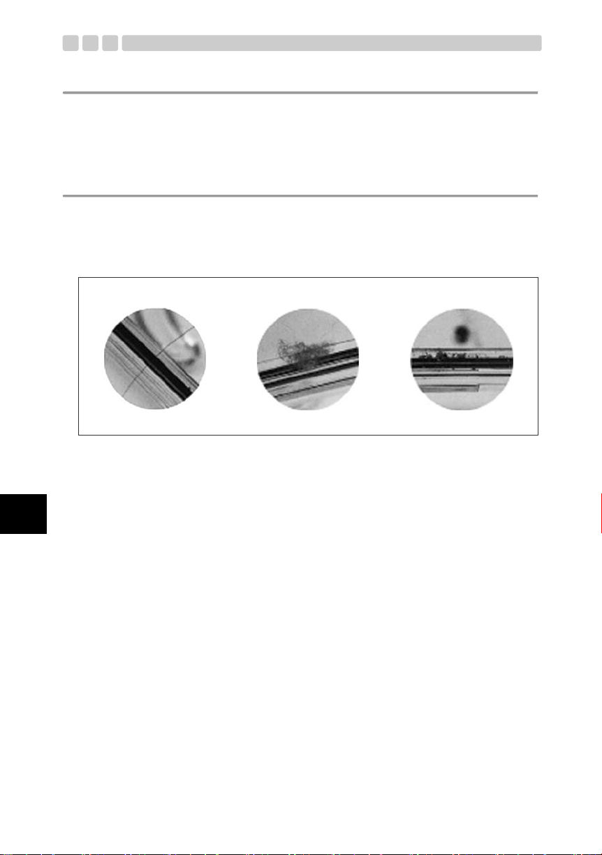
箱の中を確認します
箱の中の付属品はすべてそろっていますか。
万が一、付属品が不足していたり、破損している場合はお買上げ販売店までご連絡ください。
Jp
• プロテクター本体
(Oリングが正常であることを確
認してください。)
• シリカゲル
• Oリングリムーバー
• ハンドストラップ
• シリコングリス
• メンテナンス用アダプタ
• オリンパス代理店リスト
• 取扱説明書(本書)
JP 7
Page 9

各部名称
1 パームグリップ
※ 2 シャッターレバー
3 ハンドストラップ用つり輪
※ 4 F(露出補正)ボタン
※ 5 モードダイヤルノブ
6 アクセサリ取り付け部
7 TTLケーブルコネクタ部
8 光ファイバーケーブル差
込口、キャップ
※ 9 ズームダイヤル
0 ボディキャップ
※ a パワースイッチレバー
b 前蓋
c スライドロック
d 開閉ダイヤル
※ e INFO (情報表示)ボタン
Note:
※印のプロテクター操作部はデジタルカメラの各操作部に対応しています。プロテクター操作部を操作する
ことによってデジタルカメラの対応する機能が動作します。詳しい機能の内容についてはデジタルカメラの
取扱説明書をご覧ください。
※ f MENU ボタン
※ g S(消去)ボタン
※ h q(再生)ボタン
i ガス抜き弁
j ピックアップファインダー
※ k AEL /AFLボタン
※ l コントロールダイヤルノブ
※ m Fnボタン
※ n P(AFターゲット)ボタン
※ o ISボタン
※ p u ボタン
※ q 十字ボタン S
※ r 十字ボタン X
※ s iボタン
※ t 十字ボタン T
※ u 十字ボタン W
v 液晶モニタ窓
w 液晶フード
x 後蓋
y 液晶フードストラップ
z ホットシューケーブル取り
付け部(キャップ付き)
A 装填ガイドレール
B Oリング(POL-E05B)
C 三脚座
D Oリング(POL-E05A)
E 液晶インナーフード
F カメラ台ロック
G カメラ台
H アイカップ収納部
I ホットシューカバー収納部
Jp
JP 8
Page 10
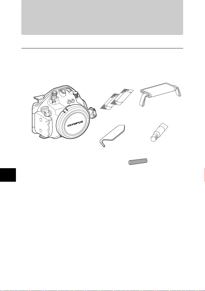
別売の防水ポートを取り付けます
本製品はデジタルカメラに装着されているレンズに合わせ、プロテクター本体前面にレンズ用の防水
ポートを装着し、水中でご使用いただけます。
• プロテクター本体への防水ポートの装着は、防水ポートに付属の取扱説明書をよくお読みのうえ装着
してください。
• 本製品付属のシリコングリスを、装着する防水ポートの O リング部およびプロテクター本体の防水
ポート取り付けネジ部に、適量を塗布します。
• 防水ポートをプロテクター本体へ時計回りに止まるまで静かにねじ込みます。
防水ポート取り付けネジ部
シリコングリス
注意:
本製品は水深40m以内の水中でご使用ください。たとえ装着される防水ポート等が40mよりも深い水深に対
応していても、ご使用可能な水深は40m以内に制限されます。
Jp
ハンドストラップを取り付けます
プロテクター本体にハンドストラップを取り付けましょう。
ハンドストラップ
注意:
• 上図にしたがってストラップを正しく取り付けてください。
• ハンドストラップ用つり輪は、プロテクター本体のパームグリップ側の上下に 2ヶ所あります。ハンドス
トラップ両端を、必ず2ヶ所のハンドストラップ用つり輪に確実に取り付けてご使用ください。
• 万が一、誤った取り付けによりストラップがはずれて本体を落とすなどした場合、損害など一切の責任は
負いかねますのでご了承ください。
JP 9
ハンドストラップ用つり輪
Page 11
基本操作をマスターします
デジタルカメラを装填する前に、プロテクターの基本操作をマスターしましょう。
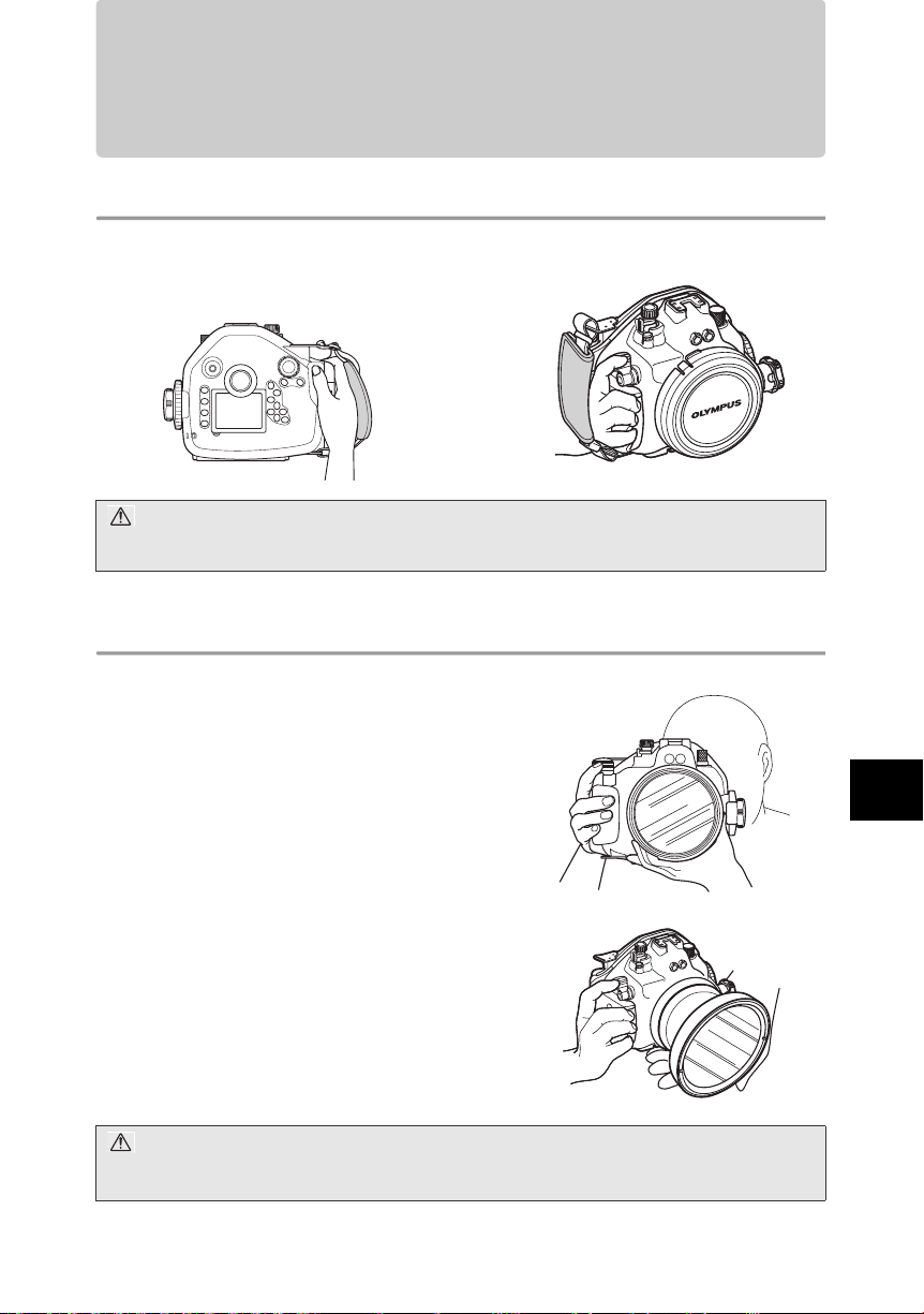
プロテクターの構え方
両手でしっかり持ち、脇をしめプロテクターのピックアップファインダーを通して撮影画面を確認で
きるように構えます。
良い例 悪い例
注意:
• 防水ポートに無理な力を加えないでください。
• 防水ポートのレンズ窓などに指がかからないようにご注意ください。
シャッターレバーの押し方
シャッターレバーを押すときは、カメラぶれが起きない
ように注意しながら静かにレバーを操作します。
モードダイヤルノブの使い方
本プロテクターには、装填されるデジタルカメラのモー
ドダイヤルに対応して、同感覚で操作できるモードダイ
ヤルノブを装備しています。プロテクターにデジタルカ
メラを装填後、撮影する前に必ずモードダイヤルノブが
操作できることを確認してください。
注意:
モードダイヤルノブがデジタルカメラのモードダイヤルに確実にセットされたことを確認してください。デ
ジタルカメラのモードダイヤルは回転する範囲が限られています。プロテクターのモードダイヤルノブを回
転させるときに、デジタルカメラのモードダイヤルの回転幅以上に回さないでください。
Jp
JP 10
Page 12
ズームダイヤルの使い方
装填されるデジタルカメラのズームリングやフォーカ
スリングに対応して、本プロテクターのズームダイヤル
を操作することによりズームやマニュアルフォーカス
の操作が可能です。
プロテクターのズームダイヤルにより操作可能なレンズのズームリングやフォーカスリングは、デジ
タルカメラに装着されるレンズにより異なりますのでご注意ください。詳しくは別売の防水ポートに
付属の取扱説明書をご参照ください。
防水ポート 対応レンズ ズームリング フォーカスリング 備 考
PPO-E01
PPO-E02
PPO-E03 50mm Macro
PPO-E03
+PER-E01
PPO-E04
+PER-E02
PPO-E04 8mm Fisheye
PPO-E05 14-42mm
※1. 別売のフォーカスギアPPZR-E04が必要です。
※2. 別売のPPZR-E04を使用することで、レンズのフォーカスリングを360度操作可能です。
※3. 別売のフォーカスギアPPZR-E05が必要です。
14-45mm
35mm Macro
14-54mm
11-22mm
50mm Macro
+EC14
7-14mm
○ × フォーカスはAFのみとなります。
×○
○ × フォーカスはAFのみとなります。
×○
× × フォーカスはAFのみとなります。
○ × フォーカスはAFのみとなります。
×○
○ × フォーカスはAFのみとなります。
※1
※2
※3
レンズのフォーカスリングを360
度操作可能です。
MFも可能ですが、MFリングの回
転は180度の範囲となります。
レンズのフォーカスリングを360
度操作可能です。
2008年6月現在
Jp
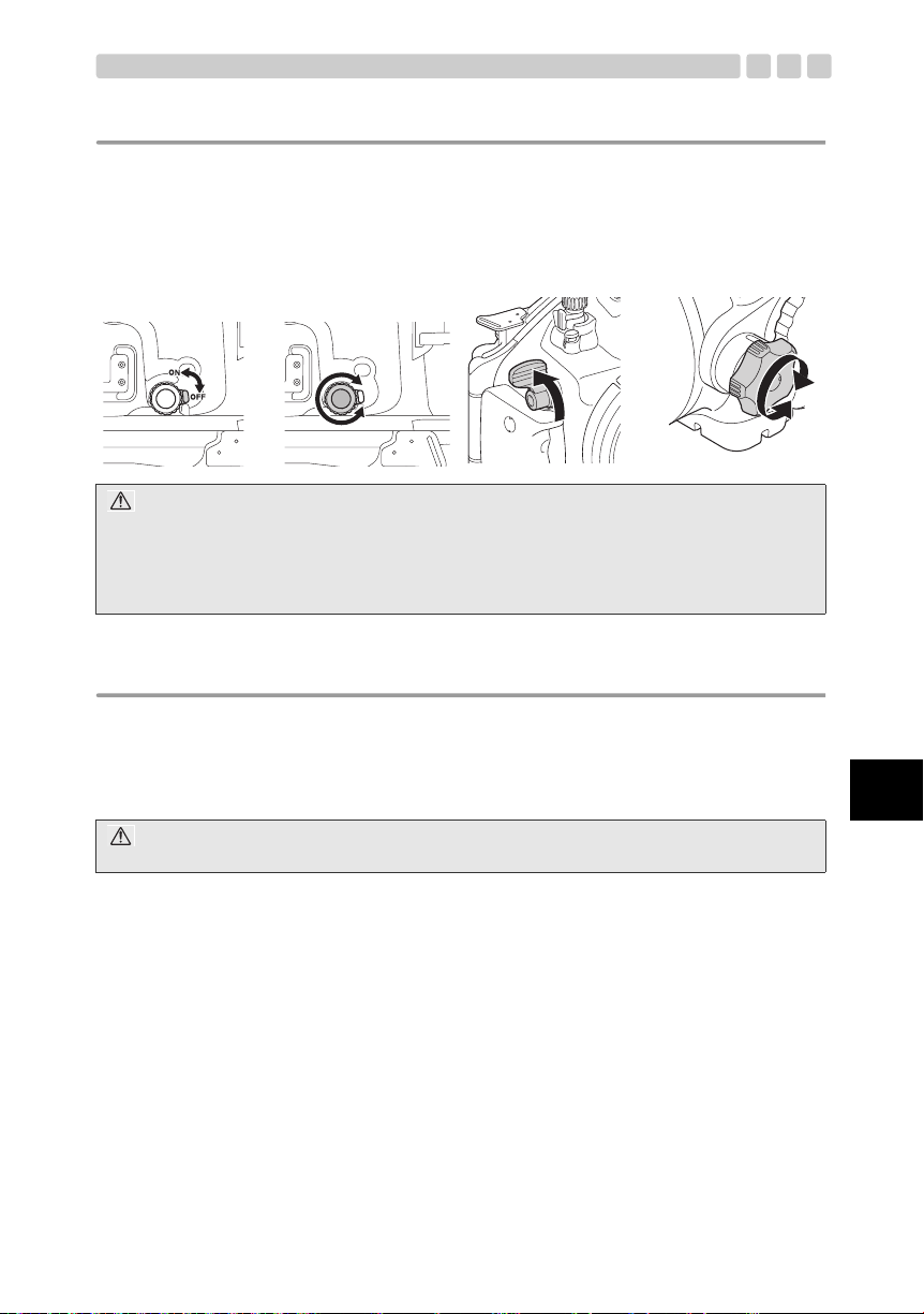
パワースイッチレバーの操作方法
本プロテクターのパワースイッチレバーを操作して、カ
メラの電源をON/OFFします。
注意:
デジタルカメラは、何も操作しない状態で一定の時間が経過すると、スリープモード(待機状態)になり、
動作を停止します。スリープモードに入るまでの時間はデジタルカメラ側で設定することが可能です。
スリープモードを解除する(動作状態にする)には、シャッターボタンなどのいずれかのボタンを押します。
詳しくは、デジタルカメラの取扱説明書を参照してください。
JP 11
パワースイッチレバー
Page 13
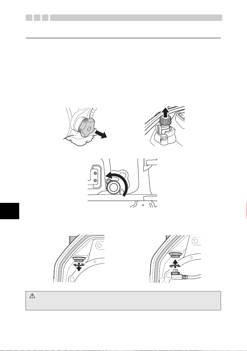
水中光ファイバーケーブルの接続
本プロテクターへ、別売の水中フラッシュ UFL-2を水中
光ファイバーケーブル(別売)で接続して撮影を行う場
合、下記手順にしたがって接続します。
• 光ファイバーケーブル差込口のキャップを取りはずし
ます。
• 水中光ファイバーケーブルのコネクタを光ファイバー
ケーブル差込口に、止まるまでしっかりと差し込みま
す。
TTLコネクタキャップの取りはずし方
本プロテクターへ、別売の水中フラッシュ等を水中TTLケーブル (別売)で接続してTTLフラッシュ撮影
を行う場合、下記手順にしたがってTTLコネクタキャップを取りはずします。
1 プロテクター本体のTTLコネクタ
TTLコネクタキャップ
2 取りはずします。
キャップを取りはずします。
1 反時計回りに回転さ
せます。
2 水中TTLケーブル(別売)のコネクタを
プロテクター本体に接続します。
3 コネクタを差し込み
ます。
4 コネクタのネジを時
計回りに軽く止まる
まで回します。
水中TTLケーブル
マークで位置を合
わせます。
TTLコネクタキャップをプロテクター本体に取り付ける場合
キャップ内側およびTTLケーブルコネクタ部のOリングに異物が付着していないことを確認し、キャッ
プを時計回りに軽く止まるまで回転して、装着します。
Oリングの確認
キャップ コネクタ部
1 キャップを装着
します。
2 キャップを時計回り
に止まるまで軽く回
します。
Jp
注意:
TTLコネクタキャップが緩んでいると、水漏れの原因となる場合があります。キャップは時計回りに止まる
まで軽く回し締めてください。
TTLケーブル固定用のネジは、軽く止まるまで時計回りに回してください。無理に締めるとはずれなくなる
場合があります。
JP 12
Page 14

Jp
TTLコネクタ部の清掃について
TTLコネクタとTTLケーブルの固定ネジ部の固着を防止するため、本製品では当該ネジ部に本製品付属
のシリコングリスを塗布します。
詳しくは本書の「TTLコネクタキャップのメンテナンス」(P.34)をご参照ください。
注意:
万が一、TTLケーブルの固定ネジ部がはずれない場合は、無理にはずそうとせず当社サービスセンターへご
相談ください。
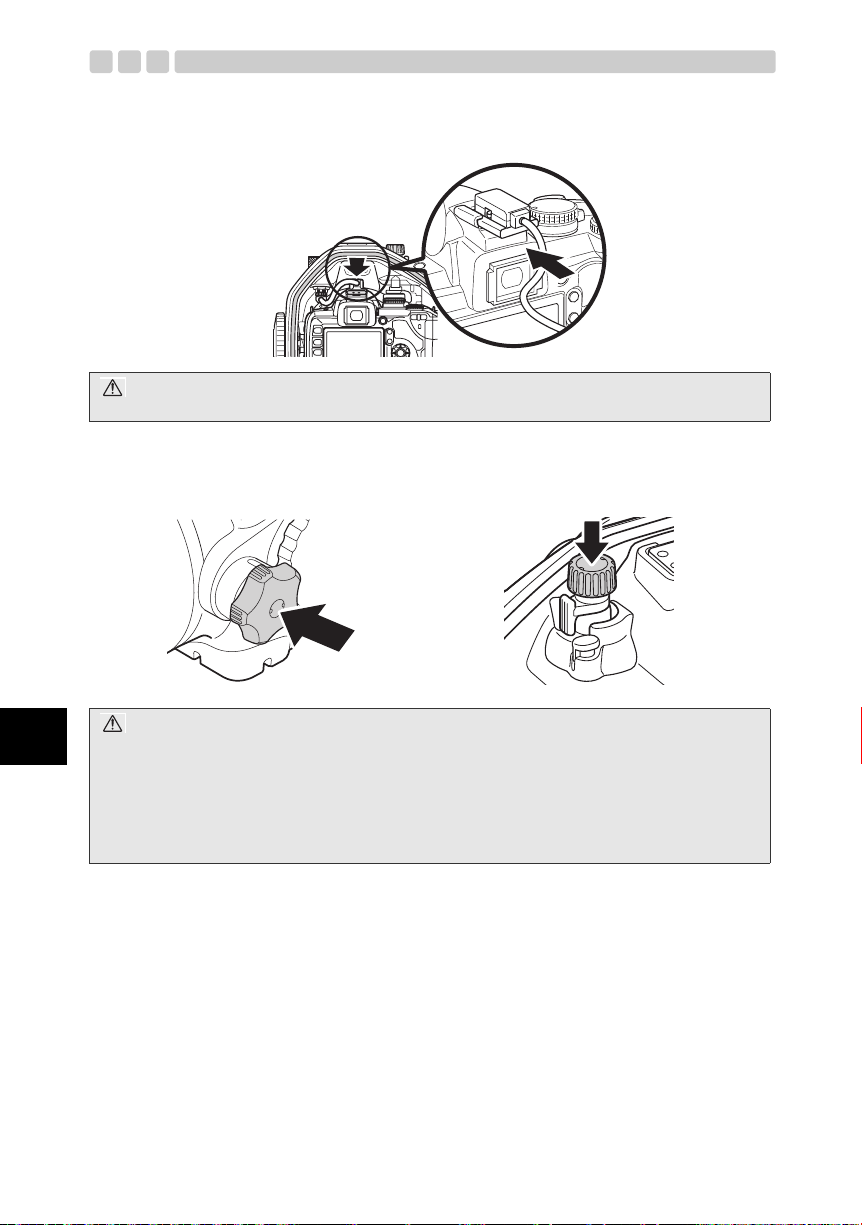
ホットシューケーブルの取り付け方
本プロテクターでTTLフラッシュ撮影を行う場合、ホットシューケーブル(別売)をプロテクター本
体コネクタとカメラのホットシュー部に接続します。
1 プロテクター内側のホットシューケーブルコネクタ部の
キャップを反時計回りに回転し取りはずします。
2 ホットシューケーブルのコネクタ側をプロテクターの
コネクタに差し込み、コネクタネジを時計回りに止まる
まで回し、固定します。
3 ホットシューケーブルのホットシューをカメラのホッ
トシューへ差し込みます。
カメラからはずしたホットシューカバーはカメラ台に
収納できます。
詳しくは本書の「デジタルカメラへのカメラ台の取り付
け方」(P.19)をご参照ください。
4 ホットシューケーブルを使用しない場合は、ホット
シューケーブルキャップをプロテクター内側のコネク
タ部に取り付け、時計回りに止まるまで回転させて固定
します。
注意:
ホットシューケーブルのコネクタ側をプロテクターのコネクタに差し込む場合は、必ずプロテクターからカ
メラを取り出してから行ってください。
JP 13
Page 15
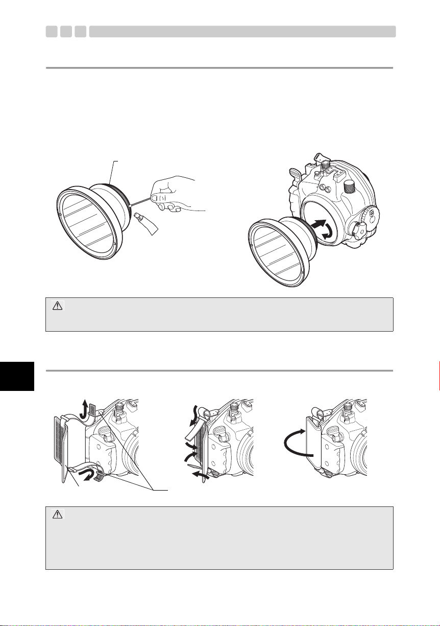
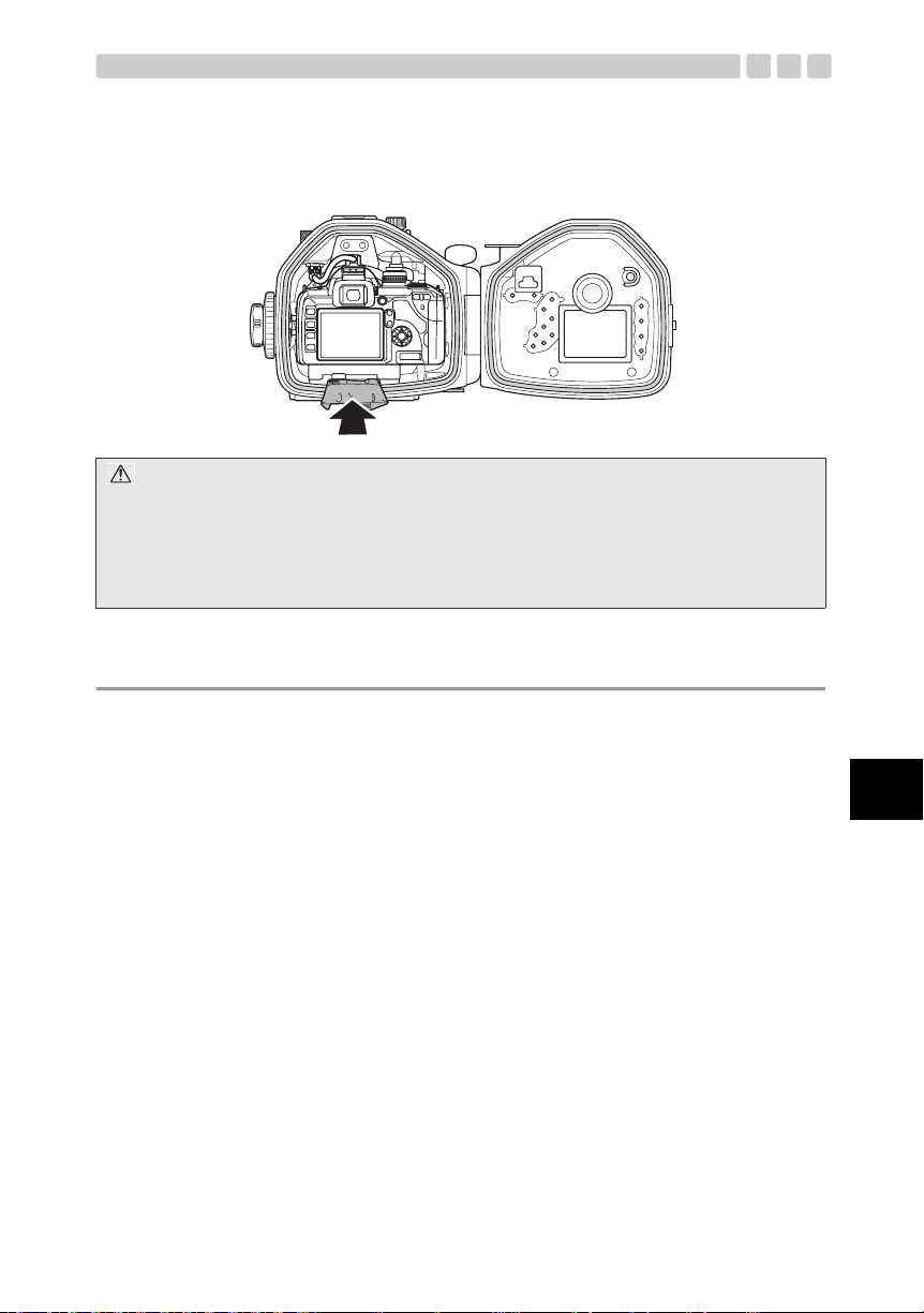
カメラ台の取り付け方・取りはずし方
本製品は、本プロテクター前蓋側の内部に設置されているカメラ台を使用してデジタルカメラの装填
を行います。
1 本プロテクターのスライドロックおよび開閉ダイヤルを
開き、後蓋を開きます。
2 カメラ台ロックを左にスライドし、ロックを解除します。
カメラ台を手前に引き出します。
3 本プロテクターへデジタルカメラを装填するために、デジ
タルカメラの三脚ネジ穴へカメラ台のネジを時計回りに
ねじ込み固定します。詳しくは本書の「デジタルカメラへ
のカメラ台の取り付け方」(P.19)をご参照ください。
4 カメラ台を本プロテクター前蓋側に設置されているカメ
ラ台装填溝へ止まるまで差し込みます。
カメラ台ロックを右にスライドし、ロックします。
5 本プロテクターの後蓋を静かに閉じ、開閉ダイヤルを閉じ
て固定します。
注意:
カメラ台が本プロテクター前蓋側に設置されているカメラ台装填溝の奥に突き当たるまで正しく装填され
ていない状態で、本プロテクターの後蓋を無理に閉じると、本プロテクターやデジタルカメラの破損の原因
となりますので十分ご注意ください。
Jp
JP 14
Page 16

Jp
2. プロテクターの事前チェックをしましょう
使用前の事前テスト
本プロテクターは、製造工程での部品の品質管理および組立工程での各機能検査などを厳重に実施し
ています。さらにすべての製品は高水圧試験機により水圧試験を実施し、仕様通りの性能が守られて
いるか検査を行い合格したものです。
しかしながら、持ち運びや、保管の状態、メンテナンスの状況など何らかの原因で防水機能にダメー
ジを受ける場合があります。
潜水前には必ず次の事前テストと、カメラ装填後に行う水漏れテストを実施してください。
プロテクターの防水部チェック
本プロテクターの防水部をそれぞれ確認します。
1 プロテクターのO リングが確実に装着され、スライドロックおよび開閉ダイヤルによって閉じられて
いること。
2 プロテクター本体に別売の防水ポートを取り付け、プロテクター本体と防水ポート部間のOリングが
確実に装着され、プロテクターと防水ポートが正しく装着されていること。
3 TTLコネクタキャップの Oリングが確実に装着され、キャップが緩みなくコネクタへねじ込まれてい
ること。
事前テスト
1 デジタルカメラをプロテクターに装填する前に、空のプロテクターをご使用になる水深に沈めて水漏
れの有無を確認してください。
2 水漏れ事故は、主に以下のことが原因で起こります。
• Oリングの取り付け忘れ
• Oリングの一部または全部が所定の溝からはずれていた
• Oリングの傷やヒビ、または変質・変形
• OリングやO リング溝、各Oリング接触面への砂・繊維くず、髪の毛など異物の付着
• 各Oリング接触面やO リング溝内の傷
• プロテクターを閉じる際の付属ストラップやシリカゲルの挟み込み
テストは上記の原因を取り除いて行うようにしてください。
注意:
• 水漏れの確認はご使用になる水深に沈めて確認することがいちばん適切です。これが難しい場合は水圧の
かからないごく浅いところでも水漏れが確認できる場合があります。面倒がらずに必ず実施してくださ
い。
• 万が一、事前テスト中に正常な取り扱いで水漏れが確認された場合はご使用を中止し、商品お買上げの販
売店またはオリンパスサービスステーションにご相談ください。
JP 15
Page 17

3. デジタルカメラを装填しましょう
デジタルカメラをチェックします
本プロテクターに装填する前にデジタルカメラをチェックします。
電池の確認
水中撮影では液晶モニタを使用して撮影後に画像の確認をしますので、電池の寿命が短くなる場合が
あります。電池残量が十分あることを確認してください。
注意:
電池消耗による撮影不能を避けるため電池はできるだけダイビングごとにフル充電状態の電池に交換して
ください。
撮影可能枚数の確認
記録メディアの撮影可能枚数が十分にあることを確認してください。
デジタルカメラのストラップやレンズキャップをはずしましょう
デジタルカメラにストラップやレンズキャップが取り付けられている場合は、必ず取りはずしてくだ
さい。
注意:
• ストラップやレンズキャップをはずさずにデジタルカメラを装填した場合、プロテクターが正しく閉まら
ずに、水漏れの原因となる場合があります。
• ストラップやレンズキャップを取りはずすときは、デジタルカメラの取り扱いには十分ご注意ください。
万が一、デジタルカメラを落とすなどで破損した場合、当社では損害など一切の責任を負いかねます。
デジタルカメラのアイカップをはずします
本プロテクターではピックアップファインダ又は
液晶モニタを通して撮影画面を確認します。
ピックアップファインダの見え方を良くするため
に、デジタルカメラのアイカップをはずして、本プ
ロテクターへデジタルカメラを装填します。
カメラからはずしたアイカップはカメラ台に収納
できます。
詳しくは本書の「デジタルカメラへのカメラ台の取
り付け方」(P.19)をご参照ください。
注意:
アイカップをはずさずにデジタルカメラを装着して本プロテクター後蓋を閉めた場合は、ピックアップファ
インダが飛び出ます。
アイカップをはずしてから、ピックアップファインダを押し込んでください。
Jp
JP 16
Page 18
デジタルカメラのフィルタを取りはずします
デジタルカメラのレンズにフィルタが付いている場合は、フィルタを取りはずしてから、プロテクター
にデジタルカメラを装填します。
注意:
デジタルカメラのレンズにフィルタを取り付けたまま、プロテクターに装填することはできません。必ず
フィルタを取りはずしてください。
カメラを準備します
装填できるデジタルカメラは?
本製品(PT-E05)はE-520専用です。
カメラの動作チェックをします
デジタルカメラの取扱説明書にしたがって、動作の確認をしてください。
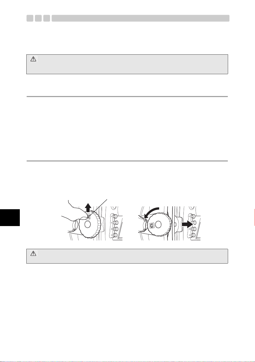
プロテクターを開けます
1 スライドロックを矢印の方向(1)にスライドしながら、開閉ダイヤルを反時計回り(2)にまわし
ます。
2 開閉ダイヤルの回転が止まる位置まで回します。
3 プロテクターの後蓋を静かに開きます。
スライドロック
1
2
Jp
注意:
開閉ダイヤルに無理な力を加えて回さないでください。破損する場合があります。
JP 17
Page 19
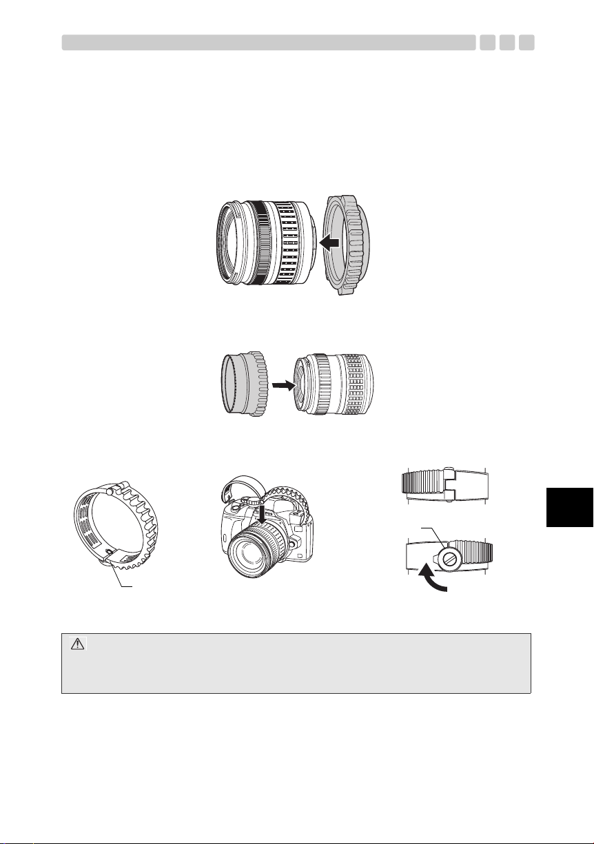
別売の防水ポートに付属のズームギア、フォーカスギアのレンズへのセット
デジタルカメラに装着されているレンズのズーム操作や、マニュアルフォーカス操作をするために、別
売の防水ポートに付属のズームギア、フォーカスギアをレンズのズームリングやフォーカスリングへ
装着します。
別売の防水ポートの取扱説明書にしたがって、装着してください。
【例1】 PPO-E05に付属の14-42mm用ズームギアのレンズへのセット
PPO-E05に付属の取扱説明書にしたがって装着します。
【例2】 別売のズーム/フォーカスギア(PPZR-E03/E04/E05)のレンズへのセット
ズーム/フォーカスギアに付属の取扱説明書にしたがって装着します。
【例3】 PPO-E01/E02/E03に付属ズーム/フォーカスギアのレンズへのセット
ロックレバー
ズーム/フォーカスギア
ロックレバーでズーム/フォーカスギアを
固定します。
注意:
• ズームギアがロックレバーで確実に固定されているか確認してください。
• 別売の防水ポートの取扱説明書にしたがって、ズームギアのレンズへの取り付け位置を確認してくださ
い。
Jp
JP 18
Page 20
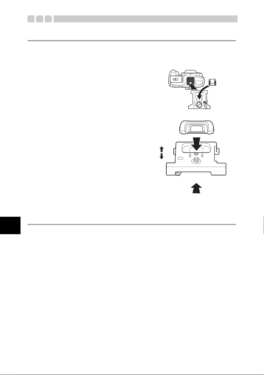
デジタルカメラへのカメラ台の取り付け方
デジタルカメラを本プロテクターに装填するために、本プロテクター前蓋側の内部に設置されている
カメラ台をデジタルカメラに取り付けます。
1 デジタルカメラのアイカップやホットシューカバーをカメラ台に収納できます。
2 デジタルカメラ底部の三脚座部分へカメラ台を取り付
けます。取り付けは、デジタルカメラの三脚穴を使用
します。
Jp
3 カメラ台には上下と前後の向きがあります。右図を参
考に間違いのないように取り付けてください。
上
下
前
後
水中エレクトロニックフラッシュUFL-2を水中光ファイバーケーブル で接続して使用する場合
1 カメラのRCモードをONに設定して、内蔵フラッシュを発光できる状態にします。
2 カメラの内蔵フラッシュをポップアップした状態でカメラを本製品に装着します。
UFL-2側の操作はUFL-2取扱説明書をご覧ください。
JP 19
Page 21
エレクトロニックフラッシュをTTLケーブルで接続して使用する場合
エレクトロニックフラッシュを、本製品にTTLケーブルで接続して使用する場合、ホットシューケー
ブルをカメラに取り付け、本製品前蓋側にあるホットシューケーブル取り付け部にケーブルを接続し
ます。この場合、カメラの内蔵フラッシュは使用できません。また、自動的にカメラの内蔵フラッシュ
がポップアップしないように、必ずカメラの自動ポップアップの設定をOFFに設定します。
1 プロテクターへカメラを装填する前に、プロテクター
のホットシューケーブル取り付け部にホットシュー
ケーブルのコネクタを差し込み固定します。
2 カメラの自動ポップアップの設定を OFF に設定します。カメラの AUTO や水中モード以外のシーン
モードでは、内蔵フラッシュは暗いときや逆光のときに自動的にポップアップします。内蔵フラッシュ
が自動的にポップアップしないようにカメラの設定を変更します。
MENU X[Y]X[f]フラッシュ X【自動ポップアップ】
【OFF】:内蔵フラッシュが自動的にポップアップしません。
3 エレクトロニックフラッシュ側の電源をカメラより先にONに設定して使用します。
エレクトロニックフラッシュをご使用の場合は、必ずカメラより先にエレクトロニックフラッシュの
電源をONにしてください。
カメラの自動ポップアップの設定がONの状態でカメラの撮影モードが AUTO または水中モード以外
のシーンモードに設定されている場合、エレクトロニックフラッシュ側の電源よりも先にカメラ側の
電源をONにすると、カメラの内蔵フラッシュが自動的にポップアップしてしまう場合がありますの
で、必ずエレクトロニックフラッシュ側の電源を先にONにしてご使用ください。
4 カメラをプロテクターに装填した後に、
カメラへホットシューケーブル本体を
装着します。
Jp
注意:
• カメラの機能設定について詳しくはカメラの取扱説明書をご確認ください。
• カメラにホットシューケーブルが接続された状態で内蔵フラッシュがポップアップした場合、内蔵フラッ
シュとホットシューケーブル本体が干渉し、ホットシューケーブル本体がカメラからはずれ、接続不良に
至る場合がありますのでご注意ください。
• 他社製のスレーブ発光タイプの水中フラッシュを使用する場合は、カメラの内蔵フラッシュをポップアッ
プした状態でカメラを本製品に装填してください。
• カメラを本製品に装填し、プロテクターのスライドロックおよび開閉ダイヤルを閉じて密閉した状態で
は、カメラの内蔵フラッシュをポップアップしたり、収納したりすることはできません。ご注意ください。
• 別売のエレクトロニックフラッシュおよびエレクトロニックフラッシュ用プロテクターを使用する場合
は、本プロテクターとフラッシュ用プロテクターを組み合わせるためのブラケット類が必要となります。
ご注意ください。
JP 20
Page 22
デジタルカメラを装填します
下記事項を確認し、本プロテクターへデジタルカメラを装填します。
• デジタルカメラの電源が OFFである。
• デジタルカメラにメディアが装着されている。
• 電池が十分に充電されている。
• デジタルカメラのストラップやレンズキャップ、フィルタが取りはずされている。
• デジタルカメラ底部の三脚穴に本プロテクター付属のカメラ台がセットされている。
• デジタルカメラファインダのアイカップがはずされている。
• デジタルカメラのレンズにズームギアやフォーカスギアが装着されている。
1 本プロテクターのズームダイヤルとモードダイヤル(パワースイッチレバーも同時にもち上がります)
を、デジタルカメラの装填時に干渉しないように引き出します。
その際、パワースイッチレバーの向きを下図のような位置に合わせます。
Jp
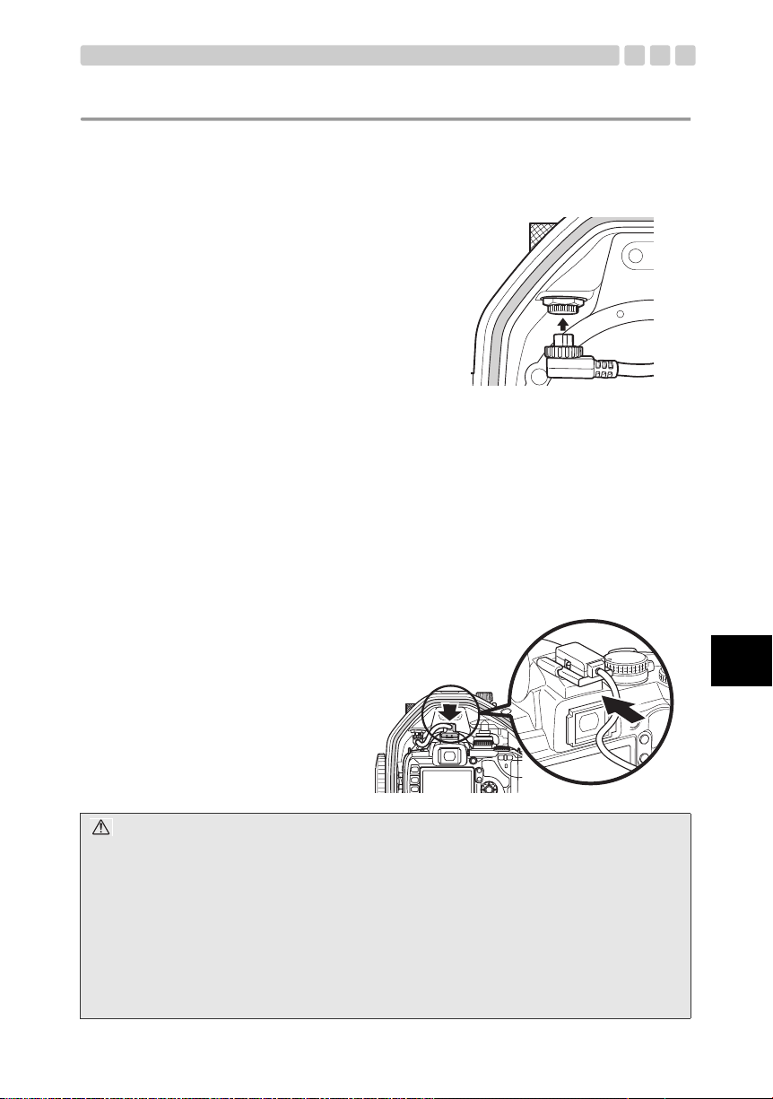
2 エレクトロニックフラッシュと TTL 接続して使用する場合、本プロテクター前蓋側の内部、左上側に
あるホットシューコネクタ部のTTLケーブルコネクタキャップを取りはずし、ホットシューコネクタ
を接続します。
反時計回りではずします。
注意:
ホットシューコネクタ固定ネジをねじ込む際は、プロテクター本体を逆さまにしてねじ込んでください。そ
の際、プロテクター本体を落としたりすることのないよう、十分にご注意ください。
JP 21
Page 23
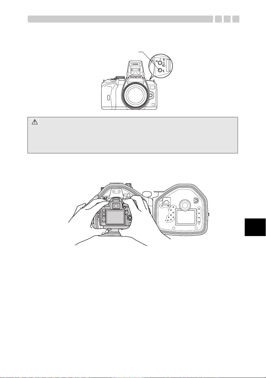
3 水中フラッシュ UFL-2と光ファイバーケーブルで接続したり、他社製のスレーブフラッシュを使用す
る場合は、カメラの#ボタンを押して内蔵フラッシュを起こします。
#ボタン
注意:
プロテクターへカメラを装填する際に必ず内蔵フラッシュをポップアップしてください。プロテクター密閉
後は、プロテクター外部からの操作で内蔵フラッシュをポップアップすることはできません。このような場
合は、カメラの自動ポップアップの設定をONに設定し、カメラの撮影モードをAUTO または水中モード以
外のシーンモードに設定して、カメラを暗い被写体へ向けシャッターを半押しして内蔵フラッシュを自動
ポップアップさせてください。
4 デジタルカメラに装着したカメラ台を、デジタルカメラとともに本プロテクターのカメラ台装填溝へ
装填します。この際、無理に装填せず、デジタルカメラが本プロテクター内部の部品に干渉しないよ
うに確認しながら静かに装填してください。
JP 22
Jp
Page 24
5 エレクトロニックフラッシュを TTL 接続して使用する場合、カメラのホットシュー部へホットシュー
ケーブル本体を装着します。また、カメラの自動ポップアップの設定をOFFに設定します。
注意:
カメラの自動ポップアップの設定を確認した後に、必ずカメラの電源をOFFにしてください。
6 デジタルカメラ装填前に引き出した本プロテクターのズームダイヤルとモードダイヤルを静かに押し
下げ、ズームダイヤルでズーム操作がスムーズにできるか、パワースイッチレバーでデジタルカメラ
の電源をON/OFFできるかモードダイヤルでカメラのモードダイヤルを操作できるか確認します。
Jp
注意:
• デジタルカメラ装填前に、別売の防水ポートの取扱説明書を確認し、レンズのズームリングやフォーカス
リングへのズームギアやフォーカスギアの装着と、本プロテクターへ装着時のズームリングやフォーカス
リングの位置決めを正しく行ってから、本プロテクターへ装填してください。
• レンズに装着したズームギアやフォーカスギアと本プロテクター側のズームダイヤルギアが正しくかみ
合っていない場合、ズームやフォーカス操作ができません。また、ギアがかみ合っていても、デジタルカ
メラを装填する際に、レンズのズーム範囲やフォーカス範囲が制限されてしまう場合があります。別売の
防水ポート付属の取扱説明書をよくご確認のうえ、正しくセットしてください。
JP 23
Page 25
シリカゲルを装填します
プロテクターを密閉する前に必ず付属の防曇剤シリカゲル一袋を、カメラ台下部とプロテクター内面
との間に入れてください。シリカゲルは両側を下に折り、横方向にして入れてください。
向きに注意
注意:
• シリカゲルは指定の場所に指定された向きで必ず奥まで挿入してください。向きを間違えると、プロテク
ター密閉時にシリカゲルの袋を挟み込み水漏れの原因となります。
• 途中まで入れたままでプロテクターを閉めるとシリカゲルの袋をOリングが挟み込み水漏れの原因となり
ます。
• 一度使用したシリカゲルは吸湿性能が衰えています。シリカゲルはプロテクター開閉時に毎回交換するこ
とをおすすめします。
装填状態のチェックをします
プロテクターを密閉する前に、以下の通り各部の最終チェックをします。
• ズームダイヤルが正しく機能するようにデジタルカメラが装填されているか。
• シリカゲルは指定された位置に奥まで挿入されているか。
• 各Oリングと接触面にゴミなどの異物が付着していないか。
• Oリングは正常に装着されてるか。
• 防水ポートが正しく装着されているか。
• TTLコネクタキャップに緩みがなく、正しく装着されているか。
• カメラの電源を ON/OFFできるか。
• カメラのモードダイヤルを操作できるか。
• エレクトロニックフラッシュと TTL 接続して使用する場合、ホットシューケーブルが正しく装着さ
れ、カメラの自動ポップアップの設定がOFFに設定されているか。
• 水中フラッシュ UFL-2と光ファイバーケーブルで接続したり、他社製のスレーブフラッシュを使用す
る場合は、カメラの内蔵フラッシュがポップアップされているか。
Jp
JP 24
Page 26

プロテクターを密閉します
1 後蓋を静かに閉じます。(Oリングが溝からはずれない
ように静かに閉じてください)
2 開閉ダイヤルを時計方向に回します。
• スライドロックの位置が真上に来るとプロテク
ターが密閉されます。
注意:
開閉ダイヤルを十分に回していない場合は、プロテクターが密閉されずに水漏れするおそれがありますの
で、ご注意ください。
Jp
JP 25
Page 27
装填後の動作チェック
プロテクター密閉後、カメラが正しく機能するか最終チェックをします。
• プロテクターのパワースイッチレバーを操作し、カメラの電源がON/OFFできるか。
• プロテクターのモードダイヤルノブを操作し、カメラのモードが正しく切り変わるか。
• プロテクターのシャッターレバーを操作し、カメラのシャッターを操作できるか。
• プロテクターのズームダイヤルを操作し、レンズのズーム操作が可能かどうか。
• その他、プロテクターの各種操作ボタンを操作して、カメラが機能するか。
注意:
• カメラが正しく機能しない場合は、本取扱説明書「デジタルカメラをチェックします」(P.16)からカメ
ラの装填をやり直してください。
• カメラをプロテクターに装填後、モードダイヤルが動くことを確認してください。
動かないときはカメラのモードダイヤルにプロテクターのモードダイヤルが正しくセットされていない
可能性があります。確実にセットしてください。
最終チェックをします
目視検査
プロテクターを密閉後、プロテクターの前蓋、後蓋の密閉部分およびプロテクター本体とポートの装
着部分の周囲を外側から見て、Oリングのよじれやはずれ、異物の挟み込みがないことを確認してく
ださい。
Jp
注意:
髪の毛や繊維くず等細かいものは目立ちませんが水没事故の原因になります。特にご注意ください。
JP 26
Page 28
最終テスト
ここではカメラ装填後の最終水漏れ検査をご紹介します。もし、水没したら…その不安から開放され
る唯一の手段です。必ず行うようにしましょう。水槽またはバスタブなどで簡単に行えます。
所用時間約5分
Jp
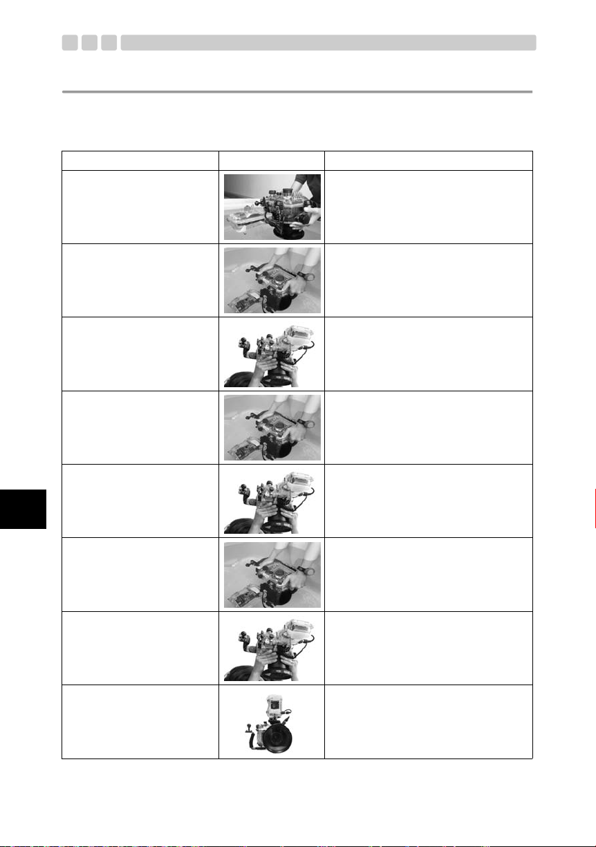
簡単水没テスト
1 ゆっくりと水の中に入れて
いきます。
2 最初は3秒だけ水につけて
みます。
3 内部に水が入っていないか
チェックします。
4 次は 30秒水につけてチェッ
クします。
5 内部に水が入っていないか
チェックします。
6 次は3分水につけてチェッ
クします。
説明画像 ちょっとヒントです
プロテクターは透明なので、水滴が入っても簡
単に確認できます。
Oリングにトラブルがあれば 3秒だけでも浸
水してきます。蓋の間から気泡が出てきません
か?
よくチェックしてください。
水から引き上げてみてプロテクターの下に水
が溜まっていないか確認します。
内部に水が垂れていませんか?
気泡が出てこないか良く確認してください。
水中の操作はまだしません。
水から引き上げて下に水がたまっていないか
確認します。
念には念を入れてよく確認してください。
気泡が出てこないか良く確認してください。
よく使うボタン類を操作して気泡が出てこな
いか確認してください。
ここで水が入らなければ大丈夫。
7 これが最後のチェックです。
シリカゲルが濡れてません
か?
8 どこにも水漏れがなければ
OKです。
JP 27
これが大切です。
シリカゲルは濡れてませんか?
よく確認してください。
中が見えるので水没検査も確実ですね。
これで安心です。
HAVE A NICE DI VE !
Page 29
4. 水中での撮影方法
ハンドストラップの使い方
本プロテクターに取り付けたハンドストラップと、本プロテクターの間に手を通し、右手で本体を支
えます。
注意:
E-520に設けられた水中撮影に適した設定(水中ワイド/水中マクロ)を使うと、簡単に水中撮影をお楽しみ
いただけます。
注意して構えましょう
撮影画面を確認します
本プロテクターでは撮影画面をピックアップファイン
ダまたは液晶モニタを使用して確認します。液晶モニタ
を通して確認する場合は、u ボタンを押してライブ
ビュー機能を使います。
Jp
シャッターレバーを静かに押します
シャッターレバーを押す際は、両手でプロテクターを
しっかり支え、カメラブレが起きないように注意しなが
ら静かにレバーを操作します。
注意:
• 動きの早い被写体を撮影する場合は、ピックアップファインダーのご使用をおすすめします。
• ライブビュー機能を使う際は、7倍 /10倍に拡大してピントを確認できます。
JP 28
Page 30

5. 撮影終了後の取り扱い方法
水滴を拭き取りましょう
水中撮影終了後、陸に上がったらプロテクターに付いている水滴を拭き取ります。プロテクターの前
蓋・後蓋の隙間、シャッターレバー、パームグリップ、開閉ダイヤルに付いている水滴などを繊維く
ずの出ない柔らかい布やエアーを使って丹念に除去します。
注意:
• 特にプロテクターの前蓋と後蓋の間、およびプロテクター本体とポート部の間に水滴が残っていると、プ
ロテクターを開けたり、ポートを着脱する際にその水滴がプロテクター内にこぼれるおそれがあります。
特に念入りに水滴を除去してください。
• プロテクターを開けたり、ポートを着脱する際、髪の毛や身体から落ちる水滴をプロテクター内部やカメ
ラに落とさぬよう十分ご注意ください。
• プロテクターを開けたり、ポートを着脱する際、手や手袋に砂・繊維くず等の異物がついていないことを
確かめてください。
• 水しぶきや砂のかかる恐れのある場所ではプロテクターを開閉したり、ポートを着脱したりしないでくだ
さい。電池や記録メディアの交換をするためにやむを得ず開閉する場合は、物陰でシートを敷く等、水し
ぶきや砂のかからないようにしてください。
• 海水のついた手でデジタルカメラや電池に触れないよう注意してください。
注意:
あらかじめ真水で濡らしたタオルなどをポリ袋に入れて用意しておき、手や指の塩分を拭き取ってから作業
するとよいでしょう。
Jp
JP 29
Page 31

デジタルカメラを取り出します
本プロテクターの開閉ダイヤルを開き、後蓋を注意して開きます。後蓋を開いた後、ズームダイヤル
とモードダイヤルを引き出し、ゆっくりと装填されているデジタルカメラを両手を使って、取り出し
ます。
デジタルカメラの取り出し手順は、本書「デジタルカメラを装填します」(P.21)の項目を逆の手順で
実施します。
1 本プロテクターの開閉ダイヤルを開きます。
2 カメラにホットシューケーブルが装着さ
れている場合は、はじめにホットシュー
ケーブルを取りはずし、本プロテクターの
ズームダイヤルとモードダイヤルをデジ
タルカメラの取り出し時に干渉しないよ
うに引き出します。次に、○の部分を両手
でつかんで、デジタルカメラを引き出しま
す。
注意:
• 開いたプロテクターは、Oリング面を必ず上に向けて置いてください。Oリング面を下に向けて置くと、
ゴミなどの異物がOリングや Oリング密着面に付着して、次回の水中撮影時の水漏れの原因になります。
• 撮影した画像の保存方法などはデジタルカメラの取扱説明書をお読みください。
• プロテクターからデジタルカメラを取り出す際、必ずプロテクターのズームダイヤル、モードダイヤルを
引き出して、デジタルカメラと干渉しない状態で取り出してください。無理にデジタルカメラを取り出す
と、本製品やデジタルカメラの破損の原因となります。
Jp
JP 30
Page 32

プロテクターを真水で洗います
ご使用後のプロテクターは空のまま再度密閉してできるだけ早く真水で十分に洗います。
海水で使用した場合は、塩分を落とすために真水に一定時間浸けておくと効果的です。
注意:
• 部分的に高い水圧がかかると水漏れするおそれがあります。プロテクターを水洗いするときは装填したデ
ジタルカメラを取り出してから行ってください。
• 本製品のシャッターレバーや各種ボタンを、真水中で操作してシャフトに着いた塩分を洗い落としてくだ
さい。分解しての清掃は決してしないでください。
• 塩分が付着したまま乾燥させた場合、機能に支障を来たすおそれがあります。使用後は必ず塩分を洗い落
としてください。
プロテクターを乾燥させましょう
真水洗い後、塩分のついていない、繊維くずの出ない乾いた柔らかい布で水滴を拭き取り、風通しの
良い日陰で完全に乾燥させてください。
注意:
乾燥させるためにヘアードライヤーなど温熱風を使用したり、直射日光に当てることはしないでください。
プロテクターの劣化・変形やOリングの劣化を早め水漏れの原因になります。
プロテクターをふく際は拭き傷を付けないようご注意ください。
Jp
JP 31
Page 33

6. 防水機能のメンテナンスをしましょう
Oリングは消耗品です。ご使用の都度メンテナンスをしてください。防水機能のメンテナンスを怠ると
水漏れの原因となります。
Oリングを取りはずします
プロテクターを開けて、プロテクターに装着されているOリングを取りはずします。
Oリングの取りはずし方
1 OリングとOリング溝の壁の間にOリングリムーバーを差し込みます。
2 差し込んだ O リングリムーバーの先端を O リングの下にくぐらせるようにします。(Oリングリムー
バーの先端で溝を傷付けないよう注意してください)
3 浮き上がったOリングを指先でつまんでプロテクターからはずしてください。
砂・ゴミなどを取り除きましょう
目視でOリングについたゴミを取り除いた後、O
リングを指でつまんで全周を軽くしごくと、砂な
どの異物の付着や傷・ヒビ割れの有無が確認でき
ます。
各Oリング溝は繊維の出にくい清潔な布、または
かすの出にくい綿棒などで付着した異物を取り
除きます。プロテクターのOリング各密着面も同
様に付着した砂・ゴミを取り除きます。
注意:
• Oリングを取りはずすときや溝内部をクリーニングするときに、シャープペンシル等先端の鋭利なものを
使用するとO リングやプロテクターに傷を付けて水漏れの原因になることがあります。
• 指先でOリングをしごいて検査する際に、O リングを引き伸ばさないように注意してください。
• O リングを洗浄する際には、アルコール・シンナー・ベンジン等の溶剤、または化学洗剤の使用は絶対に
避けてください。これらの薬品を使用すると、Oリングに損傷を与えたり、劣化を早めるおそれがあります。
Jp
JP 32
Page 34

Oリングを取り付けます
異物のないことを確認後、Oリングに薄く付属のグリスを塗り、溝にOリングをはめ込みます。この
とき、溝からOリングのはみ出しがないことを確認します。
Oリングへのグリス塗布方法
指やO リングにゴミの付着がないことを確認
1 専用グリスをつけます。
2 グリスを全体に伸ばします。
し、専用のグリスを指に5ミリ程度取り出しま
す。(グリスの量は5ミリ程度が適切)
指にとったグリスを 3本の指で挟むように
全体に伸ばしていきます。あまり力を入れ
てOリングを引っ張らないように注意し
てください。
Jp
3 傷や凹凸がないかチェック
します。
4 圧着面にグリスを塗ります。
注意:
• 撮影途中でも電池や記録メディアの交換などでプロテクターを開けた場合は防水機能のメンテナンスを
必ず実施してください。防水機能のメンテナンスを怠ると水漏れの原因となります。
• 長期間使用しない場合は、Oリングの変形を避けるために Oリングを溝からはずしてシリコングリスを薄
く塗り、清潔なポリ袋などに入れて保管してください。
• 塩分が付着したまま乾燥させた場合、機能に支障を来たすおそれがあります。使用後は必ず塩分を洗い落
としてください。
全体になじんだグリスを確認して、手の感触と
目で傷や凹凸がないかチェックしてください。
傷があったら新品のO リングに迷わず交換し
ます。
指に残ったグリスはプロテクターの圧着面の
清掃とグリスアップに使用します。
JP 33
Page 35

消耗品は取り替えましょう
• Oリングは消耗品です。プロテクターの使用回数にかかわらず、少なくとも1年以内に新品と交換さ
れることをおすすめします。
• 使用状況、保管状況によってはOリングの劣化が早まります。傷・ヒビ割れが入っていたり弾力が低
下していたら1年未満でも交換してください。
注意:
消耗品のシリコングリス、シリカゲル、本体用Oリングはオリンパス純正品をお使いください。オリンパス
サービスステーションでも購入いただけます。
TTLコネクタとTTLケーブルの固定ネジ部メンテナンス
TTLコネクタへTTLケーブルを接続する際の固定用ネジ部分は、メンテナンスを怠ると海水中での使用
による海水成分の析出等により、ネジがはずれにくくなる場合があります。
海水中での使用後は、できるだけ早く塩抜きを実施し、十分乾燥させた後にネジ部を綿棒等で清掃し、
製品付属のシリコングリスをたっぷり塗布してください。
この部分を清掃し、シリコングリスを塗
布します。
TTLコネクタキャップのメンテナンス
TTLコネクタキャップを本体から取りはずした場合は、必ずキャップ側のO リングをメンテナンスし
ます。
メンテナンス用アダプタを使用してOリングユニットをキャップ本体から取りはずします。
TTLコネクタキャップ
メンテナンス用アダプタ
Jp
1 アダプタのピンをキャップ側の穴に合わせて差し込み
ます。
2 反時計回りにアダプタを回し、Oリングユニットを取
りはずします。
3 OリングユニットについているOリングをはずしてO
リング溝を清掃し、Oリングにシリコングリスを塗布
し再び、ユニットへ装着します。
※ Oリングユニットを取りはずしたときと逆の手順でキャップ本体へ取り付けます。
Oリング
JP 34
Page 36

Jp
7. 付録
ご使用上のQ&A
Q1
: 使用可能なデジタルカメラを教えてください。
A1
: 本製品(PT-E05)はE-520 専用です。
Q2
: 本製品のみで水中撮影が可能ですか。
A2
: 水中で撮影するには、本プロテクターの他に、使用するレンズに対応した別売の防水ポート
が必要となります。
Q3
: デジタルカメラをプロテクターにセットする際の注意事項を教えてください。
A3
: 下記の点に特に注意してセットしてください。
1 デジタルカメラの電池残量が十分にあることをご確認ください。
2 記録メディアの記録残枚数をご確認ください。
プロテクターの開閉をなるべく少なくするためにも残数に余裕を持ってご使用ください。
3 デジタルカメラのレンズに、ズームギヤやフォーカスギヤが確実に装着されているかご確認
ください。
4 外部フラッシュをTTL接続してご使用の場合は、デジタルカメラにホットシューケーブルが
装着されているかご確認ください。
5 デジタルカメラのストラップやレンズキャップ、フィルター、アイカップをはずしてくださ
い。
これらをはずさずに装填すると、プロテクター密閉が正しく行えず、水漏れの原因となる場
合があります。
6 プロテクターを密閉する前に各Oリングが正常に装着されていることを確認してください。
7 各Oリング接触面にゴミ、髪の毛等の異物が付着していないことを確認してください。
8 防曇剤シリカゲルを入れましょう。オリンパスプロテクター用シリカゲルをご使用くださ
い。
9 プロテクター本体密閉用の開閉ダイヤルとポート接続部、TTLコネクタキャップが確実に閉
まっているか確認します。
Q4
: プロテクター使用時、保管時の注意事項を教えてください。
A4
: 下記の点にご注意ください。
1 プロテクターの外側からOリングの接触面を強く押したり、プロテクターをねじったりする
と防水機能が損なわれて水漏れすることがあります。
2 下記のような場所でプロテクターを使用、放置または、保管した場合動作不良や故障の原因
となります。絶対に避けてください。
• 直射日光下や自動車の中等、プロテクターが高温になる場所、異常に温度が低いところ、
極端に温度変化が激しいところ
• 火気のある場所
• 揮発性物質のある場所
• 振動のある場所
3 プロテクターにカメラを装填した状態で、以下のような取り扱いをした場合、本製品および
装填されたカメラが故障・破損するおそれがあります。絶対に避けてください。
• 物にぶつける
• 落下させる
• 重たいものをのせる
4 長時間使用しないとカビが生えたり故障の原因になることがあります。使用前に各操作部の
動作確認、事前テスト、最終テストを実施してください。
JP 35
Page 37

Q5
: プロテクター開閉時の注意事項を教えてください。
A5
: 下記の点にご注意ください。
1 水しぶきや砂のかかるおそれのない場所で、開閉してください。
2 前蓋と後蓋のすき間、バックル等凹凸のある個所に付着した水滴を拭き取ってください。
開けたときにプロテクター内に水滴が流れ込むおそれがあります。
3 プロテクターを開ける際に、髪の毛や身体から、プロテクター内やカメラの上に水滴が落ち
ないようご注意ください。
4 開いたプロテクターのOリングとOリング接触面に、砂、繊維くず等異物の付着がないこと
を確認してください。取りはずしたプロテクタ本体とポート部のOリング面も同様に確認し
てください。
5 海水のついた手でカメラや記録メディアに触らないようにしてください。
6 撮影中に水滴等、水漏れの兆候を発見した場合は、直ちに潜水を中止し、再度、水漏れのテ
ストを行い水漏れの有無を確認してください。カメラが濡れていたら水分を拭き取り動作を
確認してください。
Q6
: 使用後のプロテクターの取り扱いを教えてください。
A6
: 使用後のプロテクターはなるべく早くカメラを取り出し、真水で洗ってください。海で使用
した場合は塩分を落とすために一定時間浸けておくと効果的です。真水の中でボタン・レバー
を操作し軸回りの塩分を洗い流してください。水洗い終了後塩分の付いていない乾いた布で
水分を拭き取り、陰干しで乾燥させてください。乾燥させるためにヘアドライヤー等の温熱
風を使用したり、直射日光にさらすことは避けてください。高温や直射日光にさらすとプロ
テクターの変形・変色・破損や O リングの劣化の原因となります。プロテクター内部は乾い
た繊維くずの出ない柔らかい布で拭いてください。Oリングをはずして塩分・砂・埃等の付
着物を拭き取り、さらにOリングがはめ込まれていた溝と、Oリングが接触していた面も同
様に付着した汚れを拭き取って乾燥させてください。Oリングを溝からはずすときに先端の
鋭利なものを使用するとOリングに傷を付けて水漏れの原因となることがあります。必ず付
属のO リング取りはずし用ピックをご使用ください。
Q7
: 水漏れ有無の確認方法を教えてください。
A7
: 事前テストとカメラ装填後の最終テストで確認してください。事前テストはカメラをプロテ
クターに入れずにご使用深度に沈めて水漏れの有無を確認するのがいちばん確かですが、実
施が難しい場合は水深 1メートル程度のところやバスタブでのテストでも実施した方が安全
です。最終テストはバスタブやバケツでも実施可能です。
Q8
: 水没事故の原因を教えてください。
A8
: 水没事故は主に下記のことが原因で起こります。特に念入りに確認してください。
1 Oリングの取り付け忘れ
2 Oリングの一部または全部が溝からはずれていた
3 Oリングの傷、変質、または変形
4 Oリングへの砂・繊維くず・髪の毛等異物の付着
5 Oリング溝、Oリング接触面への砂・繊維くず・髪の毛等異物の付着
6 プロテクターを密閉する際の、ストラップ、シリカゲル包装袋等の挟み込み
7 船上から海へ放り投げたり、プロテクターを持ったまま水中に飛び込む等プロテクターに瞬
間的に強い力がかかったとき。水中に入る際は手渡しを行うなど衝撃を与えないようご注意
ください。
Jp
JP 36
Page 38

Jp
Q9
: Oリングメンテナンスの注意点を教えてください。
A9
: 下記の点にご注意ください。
1 Oリングはクリーニングの際にアルコール・シンナー・ベンジン等の有機溶剤や化学洗剤の
使用は避けてください。これらの薬品を使用するとOリングが変質し劣化を早めます。
2 グリスはオリンパス純正のシリコングリス(白キャップ)をお使いください。他社製のグリ
スは本シリコンOリングに適しておりませんので、使用すると表面が変質して防水機能を損
なうことがあります。
3 長期間使用しないときはOリングの変形を避けるためにOリングをプロテクターからはず
して専用グリスを薄く塗り、清潔なポリ袋等に入れて保管してください。再度使用する場
合はOリングに傷・ひび割れがないこと、弾力が十分にあること、表面がべとつく等の異
常がないことを確認した上で専用グリスを薄く塗り直してご使用ください。グリスは塗り
すぎても防水機能や許容耐圧は上がりません。かえって砂やゴミなどが付きやすい結果に
なります。薄く均一に塗ることで最大の効果を発揮します。
4 防水ポートのネジ部や本プロテクターのポート取り付けネジ部など、各種ネジ部は本製品付
属のシリコングリスを薄く塗布してください。
5 Oリングは消耗品です。少なくとも1年に1回は交換するようにしてください。また、ご使用
の都度メンテナンスをしてください。
6 Oリングは使用状態、保管環境などによっては劣化が促進されます。Oリングメンテナンス
時に傷、ひび割れが入っていたり、弾力がなくなっていたらすぐに新しいものと交換してく
ださい。
Q10
: プロテクターメンテナンス上の注意を教えてください。
A10
: 下記の点にご注意ください。
洗浄・防錆・防曇・修理等の目的で下記の薬品類を使用しないでください。
• プロテクターをアルコール・シンナー・ベンジン等の揮発性の有機溶剤や化学洗剤で洗
浄しないでください。洗浄は真水またはぬるま湯で十分です。
• 防錆剤等を金属部分に使用しないでください。金属部分は使用後に真水に浸し十分に洗
浄してください。錆が気になる金属部分には、使用前にあらかじめ、製品付属のシリコ
ングリスを薄く塗布してください。
• 市販の防曇剤を使わないでください。必ずオリンパス純正の防曇剤シリカゲルをご使用
ください。
• 修理等の目的で接着剤を使用しないでください。修理が必要な場合は弊社サービスス
テーションまたはお買上げの販売店にご相談ください。
Q11
: 修理について教えてください。
A11
: 修理が必要な場合は弊社サービスステーションまたはお買上げの販売店にご相談ください。
ご自分で修理・分解・改造を行わないでください。ご自分またはオリンパス指定者以外の第
三者によって修理•分解・改造を行うと保証の対象外となります。
JP 37
Page 39

Q12
: PT-E05付属品の型式を教えてください。
A12
: 下記の付属品を販売しています。
1 PT-E05本体用 O リング(POL-E05A、POL-E05B):PT-E05の本体に設置されている浸水防
止用O 型のシリコンゴム製のパッキンです。Oリングは2種類あります。他のプロテクター
用のOリングは使用できません。
2 PT-E05に装着可能な防水ポートを、ご使用いただくレンズに合わせてご用意しております。
防水ポート 耐圧水深 対応レンズ 備 考
PPO-E01 60m
PPO-E02 60m
PPO-E03 60m 50mm Macro
PER-E01 60m EC-14
PPO-E04
+PER-E02
PPO-E04 60m 8mm Fisheye
PPO-E05 40m 14-42mm
60m 7-14mm
14-45mm
35mm Macro
14-54mm
11-22mm
14-45mm用のズームギアPPZR-E01同梱。
同梱のズームギアPPZR-E01は使用できませ
ん。別売のフォーカスギアPPZR-E04を使用す
ることで、フォーカスリングを360度操作可能
です。防水ポートの対物レンズ直前での撮影倍
率は約0.6倍になります。
14-54mm および11-22mm共用のズームギア
PPZR-E02同梱。
同梱のPPZR-E01でマニュアルフォーカスが可
能ですが、フォーカスリングの回転角度は最大
で180度までに制限されます。
別売のフォーカスギアPPZR-E04を使用するこ
とで、フォーカスリングを360度操作可能です。
EC-14を使用する際、防水ポートとPT-Eシリー
ズ本体の間に装着します。
EC-14を使用する場合、レンズのズーム操作お
よびマニュアルフォーカス操作はできません。
PER-E02に7-14mm専用のズームギアPPZRE03を同梱。
別売のフォーカスギアPPZR-E05を使用するこ
とで、フォーカスリングを360度操作可能です。
14-42mm専用のズームギアPPZR-E06同梱。
PPO-E05を PT-Eシリーズ本体と組み合わせて
使用する場合、PT-Eシリーズ本体の耐圧水深が
60m仕様であっても、実際に使用いただける耐
圧水深はPPO-E05の耐圧水深40m以内に制限
されます。
Jp
3 シリコングリス(PSOLG-1/2/3):シリコンOリングメンテナンス用の専用グリスです。
4 シリカゲル(SILCA-5):プロテクターのガラス部の結露による曇りを押える乾燥剤です。5
袋入り。
5 液晶フード(PFUD-E05):プロテクターの液晶モニタ窓に取り付けて、カメラの液晶モニタ
を見やすくするフードです。
6 カメラ台(PTMO-E05):本製品にカメラを装填する際に、カメラの三脚穴に取り付けるカメ
ラ台です。
7 ハンドストラップ(PST-E02):本製品に取り付けて使用するハンドストラップです。
8 ボディキャップ(PBC-E02):本製品用ボディキャップです。
9 TTLコネクタキャップ(PTAC-E04):本製品用TTLコネクタキャップです。
※ お買い求めは大手パソコンショップ、カメラ量販店でご注文ください。
※ 操作ボタン部のOリングはお客様による交換はできません。交換が必要な場合はお買上げの販売
店または当社サービスステーションにご相談ください。有償で交換いたします。
JP 38
Page 40

仕様
対象カメラ オリンパスデジタルカメラE-520
許容水深 水深40m以内
主要材質 本体:ポリカーボネート樹脂
サイズ 幅212.5mm×高さ170.5mm×厚さ147.0mm
質量 約1,370g(カメラ、付属品含まず)
※ 外観・仕様は改善のため予告なく変更することがあります。あらかじめご了承ください。
開閉ダイヤル/シャッターレバー /パワースイッチレバー /モードダイヤルノブ/
コントロールダイヤルノブ/ズームダイヤル/カメラ台:ポリカーボネート樹脂
ポート取り付け部/ピックアップファインダ枠/別売ブラケット取り付け部/
ズームダイヤルギア/TTLコネクタキャップ:アルミニウム
各操作ボタン軸/ハンドストラップ用つり輪:ステンレス
ボディキャップ:ABS樹脂
Oリング/液晶インナーフード:シリコンゴム
液晶フード:NBRゴム
Jp
JP 39
Page 41

Page 42

Thank you for buying the Underwater Case PT-E05.
Please read this instru ction manual care fully a nd use the p roduct safely and c orrectly. Please keep
this instruction manual for reference after reading it.
Wrong usage may cause damage to the camera ins ide t he Case due to wat er leakag e, and repair
may not be possible.
Before use, perform an advance check as described in this manual.
Introduction
z Unauthorized copying of this manual i n part or in full, except for private use, is prohibi ted.
Unauthorized reproduction is st rictly prohibited.
z OLYMPUS IMAGING CORP. shall not be responsi ble in any way for los t profit s or any c laims by third
parties in case of any damage occurring from improper use of this product.
z OLYMPUS IMAGING CORP. shall not be respo nsible for dama ge, los t pro fits , etc . c aused by los s of
image data because of defects, disassembly, repair or modification of this product by people other
than third parties specified by OLYMPUS IMAGING CORP. or for oth er reasons.
Please read the following items before use
z This Case is a precision device designed for use at a water depth within 40 m. Please handle it with
sufficient care.
z Please use the Case correctl y af ter sufficient understanding of the contents of this manual in regard
to handling of the Case, checks before use, maintenance, and storage after use.
z The Case must be used in combination with the separately available Waterproof Port.
z OLYMPUS IMAGING CORP. shall in no way be responsible for accidents involving immersion of a
digital camera in water. In additi on, expenses incurred for damage of internal materials or loss of
recorded contents due to water entering the camera will not be compensated.
z OLYMPUS IMAGING CORP. shall not pay any compensation for accidents (injuries or material
damage) at the time of use.
En
For safe use
This instruction manual u ses various pictogra phs for c orrect u se of t he produc t and t o preven t dang er to
the user and other person, as we ll as property damage. These pictographs and their meanings are
shown below.
WARNING
CAUTION
EN 1
This shows the content regarding assumption of possibility of human death or
severe injury in case of handling with disregard of this indication.
This shows the contents regarding as sumption of possibili ty of inju ry or damage
to property in case of ha ndling with disregard of this indication.
Page 43

WARNING
1 Keep this product out of the reach of babies, infants, and children. There is the possibility of
occurrence of the following types of accidents.
• Injury by dropping onto the body from heights.
• Injury from parts of the body getting caught in parts which open and close.
• Swallowing of small parts. Please c onsult a physician immediately if any parts have been
swallowed.
2 Do not store digital camera with batteries i nserted in this product.
Storage with a battery insert ed may lead to leakage of the battery liquid and fire hazard.
3 The Case must be used in combination with the Waterpro of Port available separately. Remember
that the Case cannot be used without the Waterproof Port.
4 If leakage of water should occur with a camera installed in this product, quickly remove the battery
from the camera. There is the poss ibility of ignition and explos ion from generation of hydrogen gas.
5 This product is made of resin. There is the possibility that injuries may be caused when it bec omes
broken due to strong impact with a r ock or other hard objects. Please handle it with s ufficient care.
6 The silica gel and the silicon grease for this product are inedble.
CAUTION
1 Do not disassemble or modify this product. This may cause water leakage or defect. In case of
disassembly or modi fication by any party ot her than tho se appointed by OLYMPUS IMAG ING CORP.
the guarantee shall not appl y.
2 Do not place this product at locations with abnormally high or low temperatures or at locations with
extreme temperature changes. The product may deteriorate.
3 Opening and closing at locations with much sand, dust, or dirt may impair the wate rproof
characteristic and cau se water leakage. This should be avoided.
4 This product has been designed and manu factured fo r use at a water dep th within 40 m. Please note
that diving to a depth in excess of 40 m may cause permanent deformation or damage to the Case
and the camera inside, or may lea d to water leakage.
5 Jumping into the water with the Case in your pocket or in your hand, throwing the Case from a boat
or ship into the water, and other rough handling may cause water leakage. Plea se handle with
sufficient care, when handing it over from hand to hand etc.
6 If the camera on the inside should become wet because of water leakag e etc. , immed iat ely wipe of f
all moisture and confirm the operat i on.
7 Please remove the O-ring when traveling by air. Otherwise air pressure may make it impossible to
open the Case.
8 For safe use of the d igital camera in this product, please read the “Instruction Manual” for the digital
camera carefully.
9 When sealing this product, take sufficient care that no foreign matter gets caught at the O-ring and
the contact surfaces.
0 The camera’s built-in flash cannot be used when the Cas e is combined with an external Olympus
flash. Also, the c amera’s buil t-i n flas h can not be pop ped up if the hot sho e cabl e is c on nect ed to t he
camera’s hot shoe. If the built-in flash is forcibly pop ped up, the connected fla sh will not work properly
and the hot shoe cable may be disconnected from the camera’s hot shoe. In this case, the camera
may also be damaged.
a The camera’s built-in flash cannot be used when the camera is in the Case.
En
EN 2
Page 44

En
Batteries
z Use only with an Olympus lithium-ion rechargeable battery (BLM-1) specially for camer a use.
z Take care that the battery electrodes do not get wet. This may cause trouble or accidents.
z Carefully read the instruction manual for the camera about other cauti ons regarding batteries.
For Prevention of Water Leakage Accidents
When water leakage occurs whil e this produc t is being used, repair of the c amera housed in this product
may become impossible. Please use while observing the following cautions.
1 When sealing this product, make s ure that no ha ir, fib er, sand p article or other for eign matter stick to
the O-ring, and also t o the cont act surf ace. Ev en a single strand of hair or a singl e grain of sand may
cause water leakage. Please chec k with special care.
Examples of foreign matter sticking to the O-ring
Hair Fibers Grains of sand
2 The O-ring is a consumable product. Ple ase re place it at lea st on ce a y ear with a new p iec e. Bef or e
each use, perform the proper maintenance.
3 Deterioration of the O-ring will accelerate according to the usag e conditions and the storage
conditions. Immedi ately replace the O-ring with a new piece if it is damage d, crack ed, or ha s lost its
elasticity.
4 During maintenace of O-ring, clean the inside of the O-ring groove and conf irm the absence of dirt,
dust, sand, and other foreign mat ter.
5 Apply the specified silicon grease to the O-ring.
6 The waterproof function is not effective if the O-ring is not installed correctly. When installing the O-
ring, take care that it does not project from the groove and that it is not twisted. Also, when sealing
the Case, close the lid after confirming that the O-ring has not come out of the groove.
7 This product is an airtight construction made of plast ic (polycar bonate ). When it is l eft for a long t ime
in a car, on a boat, at the beach, or at other places reaching a high tempe r ature, or when it is
subjected to uneven ext ernal force for a long time, it may be deformed and the waterproof function
may be lost. Pay suff icient at tention to t emperatu re contr ol. Also do not place hea vy object s onto t he
product during storage or transport, and avoid unreasonable st orage.
8 When the O-ring contact surface is pressed strongly fro m the out side of t he Case, or whe n the Case
is twisted, the waterproof function may be lost. Take care not to exert excessive force.
9 Please use the Case only after performin g the advance test and the final check.
0 If you detect any signs of leakage, such as water drops or fogging, while photographing, get out of
the water immediately after foll owing proper scub a diving procedu res and remove any moistu re from
the camera and the Case. Then perform the leak test described in “Final check”.
EN 3
Page 45

Handling the Product
z Use or storage of the product at the following locations may cause defective operation, defects,
damage, fire, internal cloud ing, or water leakage. This should be avoided.
• Places of high temperatures, such as in direct sunlight, in a clos ed vehicle, etc., and/or where
extreme differences in temperatures exist.
• Places with open fire
• Water depths in excess of 40 m
• Places with vibrations
• Places with high temperature and humidity or with severe temperatur e changes
• Places with volatile substances
z This product is made of polycarbonate res in with exce llent impact res istance, bu t it may be damag ed
by rubbing against rocks etc. It also may break when it is hit by hard objects or i s dropped.
z This product is not a case t o sof t en impac ts to the c ame ra insi de t he pro duc t. Wh en thi s prod uct wi th
a digital camera inside is subjected to impac t or heavy objects are placed onto it, the digital camera
may become damaged. Please handle it with sufficient care.
z When the product is not used for a long time, the waterproof performance may drop because of
deterioration of the O-ring etc. Before use, always perform the advance test and the final check.
z Be careful not to ap ply excessiv e force to the port c onnector, TT L cable co nnector, zoo m dial or tr ipod
seat.
z Do not push the air vent valve from in side.
z Do not use the following c hemicals f or cleanin g, corro sion preventi on, prev ention of fogging, repair or
other purposes. When these are used for the Case directly or indirectly (with the chemicals in
vaporized state), they may cause cracking under high pressure or other problems.
Chemicals which cannot be
Volatile organic solvents,
chemical detergents
Anticorrosion agent
Commercial defogging
agents
Grease other than specified
silicone grease
Adhesive
z Do not perform operations other tha n sp ecified in this instruction manual, do not remove or modify
parts other than specified, and do not use parts other than specif ied.
Any trouble in taking pictures or with the equipment resulting from the above actions shall not be
covered by the guarantee.
z OLYMPUS IMAGING CORP. shall in no way be responsible for accidents involving immersion of a
digital camera in water.
z OLYMPUS IMAGING CORP. shall not pay any compensation for accidents (injuries or material
damage) at the time of use.
used
Do not clean the Case with alcohol, ga so line, thinner or other volatile
organic solvents or with chem ical detergents etc. Pure water or
lukewarm water is sufficient for cleaning.
Do not use anticorros ion agents. Pure water is sufficient when washing
the metal parts as stainless st eel and brass are used.
Do not use commercial defogging agents. Always use the specified
desiccant silica gel.
Use only the specified silicone grease for the silicon O-ring, as
otherwise the O-ring surface may deteriorate and water leakage may
occur.
Do not use adhesive for repairs or other purposes. When repair is
required, please contact a dealer or a service station of OLYMPUS
IMAGING CORP.
Explanation
En
EN 4
Page 46

Contents
Introduction ............................................................................................................................1
Please read the following items before use ...........................................................................1
For safe use........................................................................ ........................................... ........ 1
Batteries.................................................................................................................................3
For Prevention of Water Leakage Accidents.......................................................................... 3
Handling the Product................................................................. .... .... .. ......... .... .... .. .... ............4
1.Preparations.............................................................................................................7
Check the contents of the package........................................................................................7
Names of the parts...........................................................................................................8
Install the Waterpr o o f Port .............. ........................................................... ............................9
Attach the hand strap............................................................................................................. 9
Mastering basic Case operations......................................................................................... 10
How to hold the Case..................................................................................................... 10
How to Press the Shutter Lever..................................................................................... 10
How to use the mode dial knob...................................................................................... 10
How to use the zoom dial...............................................................................................11
How to control the power switch lever...........................................................................11
Connecting the underwater optical fiber cable............................................................... 12
Removing the TTL connector cap..................................................................................12
Cleaning the TTL connector............................................................................... .. ....... .. .13
How to connect the hot shoe cable................................................................................13
How to attach and detach the camera table .................................................................. 14
2.Advance check of the Case ..................................................................................15
Advance test before us e......................................................................................................15
Check the waterproof part s of th e Case................................................................. ....... 15
Advance test.............................................. ....................................................................15
En
3.Installing the digital camera .................................................................................16
Check the digital camera......................................................................................................16
Battery Confirmation............. ............................. ............................................................16
Check the remaining number of pictures....................................................................... 16
Remove the strap and lens cap from the camera.......................................................... 16
Remove the ey e c u p from the digita l c a me r a . . ............................................................... 16
Remove the filter from the digital camera......................................................................17
Prepare the digital camera................................................................................................... 17
Compatible digital camera.................... .........................................................................17
Checking camera operation...........................................................................................17
Open the Case................... ............... ...................................................................................17
Attach the zoom and focus gears provided with the optional underwater port to the
lens................................................................................................................................18
How to attach the camera table to th e digital camera..................... ..................................... 19
Using the UFL-2 underwater electronic flash with the underwater optical fiber cable.......... 19
Using the electronic flas h with the TTL cable............................................. ..........................20
Insert the digital camera in the Case.................................................................................... 21
EN 5
Page 47

Insert the silica gel.........................................................................................................24
Check the loading status......................................................................................................24
Seal the Case............... ........................................................................................ ................ 25
Check the operation of the loaded camera ..........................................................................26
Perform the final che ck s.......................................................................................................26
Visual Inspection............................................................................................................26
Final Test ............................................................................................................................. 27
4.Underwater Shooting............................................................................................28
How to use the hand strap ...................................................... .... .. .. .. .... ..... .... .. .. .... .. .. ....... .. .28
Hold the Case carefully....................................................................................................... .28
Confirm that you can see an image in the pick-up finder or LCD monitor. .................... 28
Gently press the shutter lever........................................................................................28
5.Handling After Shooting.......................................................................................29
Wipe off any waterdrop........................................................................................................29
Unload the digital camera ....................................................................................................30
Wash the Case with pure water........................................................................................... 31
Dry the Case........................................................................................................................31
6.Maintaining the Waterproof Function..................................................................32
Remove the O-ring...............................................................................................................32
Procedure ..... ................................................................................................................. 32
Remove any sand, dirt, etc..................................................................................................32
Install the O-ring................................................................................................................... 33
How to Apply Grease to the O-ring...................................................................................... 33
Replace consumable products.............................................................................................34
Maintenance of the threaded sections on the TTL cable and TTL cable connector............. 34
Maintenance of the TTL Connector Cap.............................................................................. 34
7.Appendix................................................................................................................35
Q & A on use........................................................................................................................ 35
Specifications....................................................................................................................... 39
En
EN 6
Page 48

1. Preparations
Check the contents of the package
Check that all accessories are in the box.
Contact your dealer if accessories are missing or damaged.
• Silica gel
• Hand strap
En
• Case body
(Check that the O-ring is normal.)
• O-ring remover
• Silicone grease
• Maintenance adapter
• Instruction manual (this manual)
• Authorized distributors list/Authorized
service centres list
EN 7
Page 49

Names of the parts
1 Palm grip
*2 Shutter lever
3 Hand strap ring
*4 F (Exposure correction)
button
*5 Mode dial knob
6 Accessory mount
7 TTL cable connector
8 Optical fiber cable inse rtion
slot, cap
*9 Zoom dia l
0 Body cap
*a Power switch lever
b Front lid
c Slide lock
d Open/close dial
Note:
Case operation parts marked by * corresponds to the operation parts of the digital camera. When the
operation parts of the Case are operated, the corresponding functions of the digital camera will operate. For
details of the functions, refer to the instruction manual for the digital camera.
*e INFO (Info display) button
*f MENU button
*g S (Erase) button
*h q (Play) button
i Air vent valve
j Pickup finder
*k AEL/AFL button
*l Control dial knob
*m Fn button
*n P (AF target) button
*o IS button
*p u button
*q Cross-cursor button S
*r Cross-cursor button X
*s i button
*t Cross-cursor button T
*u Cross-cursor button W
v LCD monitor window
w LCD hood
x Rear lid
y LCD hood strap
z Hot shoe cable connectors
(w/caps)
A Loading guide rails
B O-ring (POL-E05B)
C Tripod seat
D O-ring (POL-E05A)
E LCD inner hood
F Camera table lock
G Camera table
H Eyecup storage space
I Hot shoe cover storage
space
En
EN 8
Page 50

Install the Waterproof Port
To enable the Case to be used underwater, the sep arately available Waterproof Port for the camera lens
must be installed on the Case. Align the Water proof Port wit h the position whe re the came ra lens will be
when the camera is loaded in the Case.
• Refer to the instr uction manua l provided with the Waterpr oof Port bef ore attac hing the Wat erproof Port
to the Case.
• Apply the provided Silicon grea se to the O-ring s ection of the Wate rproof Port and t he Waterproof Port
mounting thread on the Case.
• Screw the Waterproof Port into the Case by turning it clockwise all the way.
Waterproof Port mount thread
Silicon grease
CAUTION:
The Case should not be used underwater at depths that exceed 40 meters. Even when the attached
underwater lens port or other equipment is able to withstand depths exceeding 40 meters, the Case itself
cannot be used at depths of more than 40 meters.
En
Attach the hand strap
Attach the hand strap to the Case.
Hand strap ring
Hand strap
CAUTION:
• Be sure to install the hand strap correctly as shown above.
• Two hand strap rings are attached to the side of the Case, at the top and bottom of the palm grip. Before
using the Case, be sure to attach the ends of the strap to the two hand strap rings.
• OLYMPUS IMAGING CORP. shall bear no responsibility for damage caused by dropping the Case because
of incorrect installation of the hand strap.
EN 9
Page 51

Mastering basic Case operations
Before loading the digital camer a, be sure you are comfortable with the basic Case ope rations.
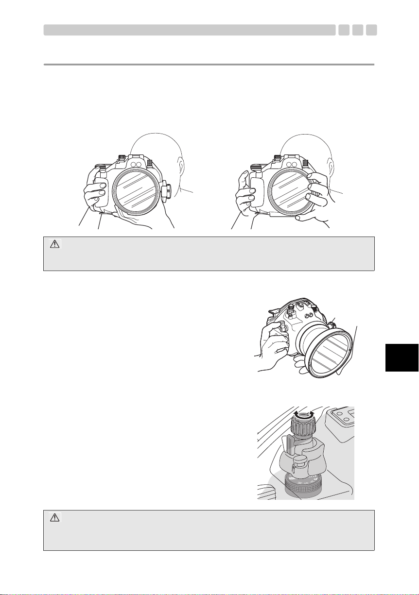
How to hold the Case
Press your arms against your s ide s and hold t he Case fir mly wit h b oth h ands at a height wher e you c an
comfortably view the image through the Case’s pickup vie w finder.
Correct Wrong
CAUTION:
• Do not apply excessive force to the waterproof port.
• Be careful not to block the waterproof port’s lens window.
How to Press the Shutter Lever
When pressing the shutter lever, press it gently, so that
there will be no movement of the camera.
How to use the mode dial knob
The Case has a mode dial knob that that functions the
same way as the mode dial of the digital camera loaded
in the Case. After loading t he digi tal came ra in t he Case,
be sure to check that the mode dial knob functions
properly before taking any photographs.
CAUTION:
Make sure that the Case’s mode dial knob is properly positioned on camera’s mode dial. Remember that the
rotation range of the camera’ s mode dial is limited. Do not turn the Case’s mode dial knob beyond the rotation
range of the camera’s mode dial.
En
EN 10
Page 52

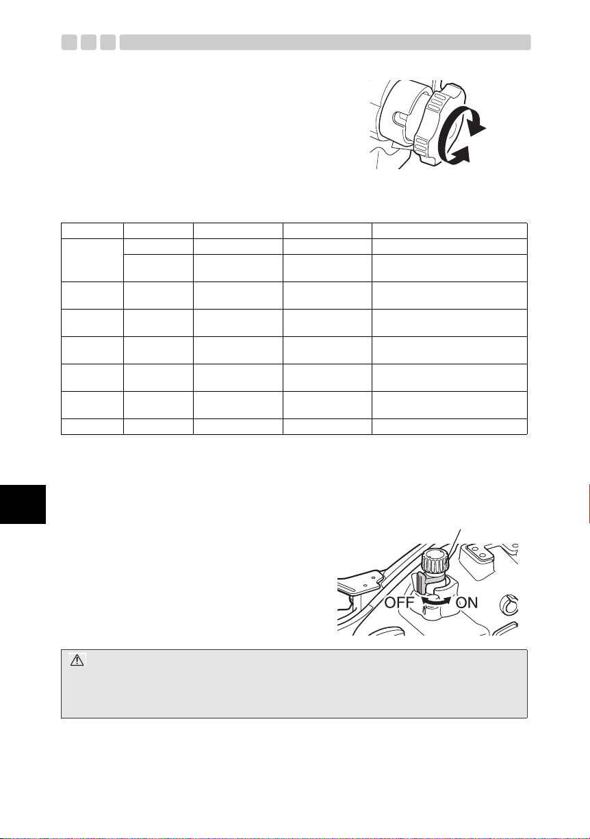
How to use the zoom dial
The Case’s zoom dial can be used to control the digital
camera’s zoom ring or its manual focus ring. Which
operation is available depends on the lens being used.
Whether or not the Case’s zoom ring can control the camera’s zoom ring and focus ring depends on
which lens is mounted on the digital camera. F or details, refer to the instruction manual of t he optional
waterproof port.
En
Waterproof
Port
PPO-E01
PPO-E02
PPO-E03 50 mm Macro Not Controllable Controllable
PPO-E03
+PPO-E01
PPO-E04
+PER-E02
PPO-E04 8 mm Fisheye Not Controllable Controllable
PPO-E05 14-42 mm Controllable Not Controllable
*1. The optional PPZR-E04 focusing gear is required.
*2. The focus ring on the lens can be turned 360° by using the optional PPZR-E04.
*3. The optional PPZR-E05 focusing gear is required.
Applicable
Lens
14-45 mm Controllable Not Controllable
35 mm Macro Not Controllable Controllable
14-54 mm
11-22 mm
50 mm Macro
+EC14
7-14 mm Controllable Not Controllable
Zoom Ring Focus Ring Note
*1
Controllable Not Controllable
*2
Not Controllable Not Controllable
*3
How to control the power switch lever
Move the power switch lever of the Case to turn the
camera ON and OFF.
Only autofocusing is
possible.
The lens’ focus ring can be
rotated by 360°.
Only autofocusing is
possible.
Manual focusing is possible
but the MF ring rotation
range is limited to 180°.
Only autofocusing is
possible.
Only autofocusing is
possible.
The lens’ focus ring can be
rotated by 360°.
Only autofocusing is
possible.
As of June 2008.
Power switch l e ve r
CAUTION:
When the digital camera has not been operated for a certain period of time, the sleep mode (standby status)
will be engaged. The duration before the sleep mode is engaged can be set on the digital camera.
To exit the sleep mode (and restore camera functions), press any button (such as the shutter button).
For details, refer to your digital camera’s instruction manual.
EN 11
Page 53

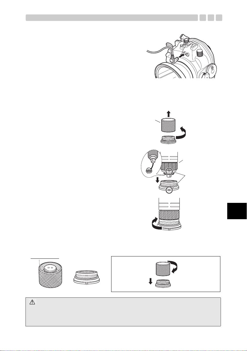
Connecting the underwater optical fiber cable
To connect the separately available UFL-2 underwater
flash to the Case using an un derwate r opt ical f ibe r cable
(optional), follow the proced ures below.
• Remove the cap of the o ptical fiber cable insertion s l ot.
• Put the underwater optical fiber cable plug all the way
into the optical fiber cable insertion slot.
Removing the TTL connecto r cap
To perform TTL flash shootin g by connecting th e separately availab le underwater fla sh or other produ cts
to the Case using the underwater TTL cable (optional), remove the TTL connector cap as described
below.
1 Remove the TTL connector cap from
the Case.
2 Connect the underwater TTL cable
(optional) to the TTL connector on the
Case.
TTL connector cap
1 Turn counter
clockwise.
3 Insert into the
connector.
4 Turn the threaded
section of the
connector clockwise
lightly until it stops.
2 Remove.
Underwater TTL
cable
Use this mark to
align the position.
How to attach the TTL connector cap to the case
Make sure there is no foreign matter attached to the O-rings inside the cap and on the TTL cable
connector. To secure the cap, gently turn it clockwise until it stops.
Check O-rings
2 Gently turn the cap
clockwise until it
stops.
1 Attach the cap to
the case.
Cap Connector
En
CAUTION:
If the TTL connector cap is loose, water penetration may result. Be sure to gently turn the cap until it stops to
make sure it is firmly secured.
Do not turn or tighten the TTL cable too hard. If it is too tight, it may be difficult to loosen and remove.
EN 12
Page 54

Cleaning the TTL connector
If the threaded sections of the TTL cable and TTL cable connector stic k to each other, the cable may
disconnect from the connector. To prevent this, apply silicone grease, provided with this case to the
threaded sections.
For details, see “Maintenance of the TTL Connector Cap” (P. 34) of this manual.
CAUTION:
If you cannot disconnect the TTL cable, do not use force. Contact Olympus for support.
How to connect the hot shoe cable
To perform TTL flash shooting using the Case, connect the hot shoe cable (optional) between the
connector on the Case and the digital camera’s hot shoe.
1 Turn the hot shoe cable connector cap inside the case
counterclockwise to remove it.
2 Insert the connector of the hot s hoe cable int o the cas e’s
connector and turn the conn ector screws all the way
clockwise to connect them f irmly.
3 Insert the hot shoe on the hot shoe cable into the hot shoe
on the camera.
The hot shoe cover removed fr om the camera can be
stored in the camera table.
For details, see “How to attach the camera table to the
digital camera” (P. 19) of this manual.
En
4 When not using the hot shoe cable, attach the hot shoe
cable cap to the hot sh oe cable conne ctor inside th e case
and turn the cap all the way cloc kwise to attach it firmly.
CAUTION:
Be sure to remove the camera from the case when inserting the connector of the hot shoe cable into the
case’s connector.
EN 13
Page 55

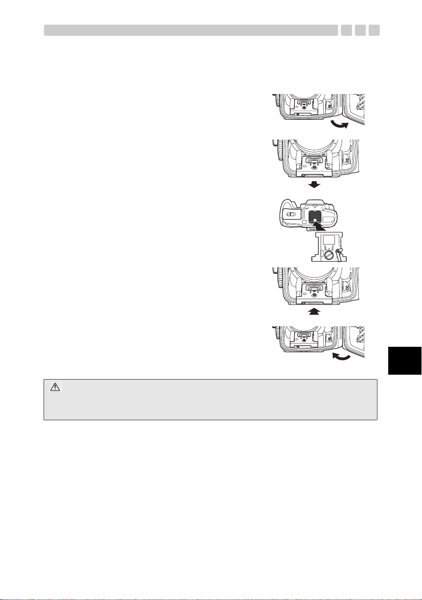
How to attach and detach the camera table
The camera table inside the front lid of the Case is used to load the digital camera into the Case.
1 Slide and hold the Case’s slide lock and open the open/
close dial, then open the rear lid.
2 Slide the camera table lock to the left to unlock the
camera table.
Slide the table towards the rear.
3 To prepare the Case for loading, screw the camera
table’s screw tightly into the camera’s tripod screw hole.
For details, see “How to attach the camera table to the
digital camera” (P. 19) of this manual.
4 Slide the camera table all the way into the camera table
loading grooves on the front-lid side of the Case.
Slide the camera table lock t o the right to lock th e camera
table.
5 Gently close the rear lid of the Case and close the open/
close dial firmly.
CAUTION:
Closing the rear lid of the Case before the camera table is inserted all the way (until it stops), into the camera
table loading grooves could damage the Case and the camera.
En
EN 14
Page 56

En
2. Advance check of the Case
Advance test before use
This Case has been the subject of thorough quality control for the parts during the manufacturing
process and thorough functi on inspections during the asse mbly. In addition, a water pressure t est is
performed with a water press ure tester for all products to confirm that the performance conforms to the
specifications.
However, depending on the carrying and storage conditions, the maintenance status, etc., the
waterproof function may be damaged.
Before diving, always perform the following advance test and the water leakage test after installation of
the camera.
Check the waterproof parts of the Case
Check the waterproof parts of the Case as described below.
1 Ensure that the Case’s O-rings are firmly attached an d secured with the s lide lock and the ope n/close
dial.
2 Ensure that the separately available Wat erproof Port is installed correctly, and that the Waterproof
Port is attached firmly to the O-ring between the Waterproof Port and Case.
3 Ensure that the O-ring of the TTL connector is attached firmly and that the cap is screwed into the
connector without loosening.
Advance test
1 Before loading the digital camer a i n t he Cas e, imme rse th e empty Case at dept h you intend to use it
and make sure there is no water leakage.
2 Main causes of water leakage are as follows.
• Forgetting to install the O-ri ng
• Part of an O-ring or an enti re O-ring is outside the specified groove.
• O-ring damage, cracks, deterio ration or deformation
• Sand, fibers, hair or other foreign matter sticking to the O-ring, the O-ring groove or the O-ring
contact surface.
• Damage to an O-ring groove or O-ring contact surface.
• Attached strap or silica gel getting caught when closing the Case.
Perform the test after the above causes have been eliminated.
CAUTION:
• The most suitable method for checking water leakage is to immerse the Case to the intended water depth.
When this is difficult, water leakage also can be checked at a shallow depth with no water pressure. Do not
feel that this is troublesome, but perform this test.
• If the advance test should show water leakage with normal handling, stop using the Case and contact your
dealer or an Olympus service station.
EN 15
Page 57

3. Installing the digital camera
Check the digital camera
Check the digital camera before load ing it in the Case.
Battery Confirmation
Underwater shooting can r educe batt ery life be cause the pic ture ha s to be checked on the LCD moni tor
before and after shooting. Make sure that you have sufficient remaining battery capacity before use.
CAUTION:
In order to avoid missing photo opportunities due to an exhausted battery, you should always have a fully
charged battery before each dive.
Check the remaining number of pictures
Check that the image storage medium has enough room for the numbe r of pictures you want to take.
Remove the strap and lens cap from the camera.
Be sure that the strap, and/or lens cap are not attached to th e di gital camera. If any of these items are
attached, be sure to remove them.
CAUTION:
• If the digital camera is loaded without removing the strap and lens cap, the Case cannot be sealed properly
and may leak.
• Handle the digital camera carefully when removing the strap and lens cap. Olympus does not assume any
liability for damage incurred if the camera is dropped.
Remove the eyecup from the digital
camera.
The Case allows you compose your shots in the
pickup viewfinder or the LCD monitor.
To improve the view of the pickup viewfi nder,
remove the camera’s eyecup b efore loading it in the
Case.
The eyecup removed from the camera c an be
stored in the camera table.
For details, see “How to attach the camera table to
the digital camera” (P. 19) of this manual.
CAUTION:
In case the digital camera is loaded in the Case without removing the eyecup and the rear lid of the Case is
closed, the pickup viewfinder pops out.
Remove the eyecup, then push in the pickup viewfinder.
En
EN 16
Page 58

Remove the filter from the digital camera
If a filter is attached to the lens of the digital camera, remove the filter before loading the digital camera
in the Case.
CAUTION:
The digital camera cannot be loaded in the Case while the filter is attached to the lens. Be sure to remove the
filter before loading.
Prepare the digital camera
Compatible digital camera
This product (PT-E05) is exclusively for use with the E-520 Digital Camera.
Checking camera operation
Refer to the digital camera’s ins tructi on manual for det ails on how to make sure the c amera is opera ting
correctly.
Open the Case
1 Slide and hold the slide lock towards the arrow direction (1) and turn the open/close dial counter
clockwise (2).
2 Turn the open/close dial to the position where it cannot be turned further.
3 Open the rear lid of the Case gently.
Slide lock
1
2
En
CAUTION:
Do not exert too much force while turning the open/close dial. Doing so may damage the dial.
EN 17
Page 59

Attach the zoom and focus gears prov ided with the optiona l underwater port to the lens .
To control the zooming and manua l focusing of the camera’s len s, att ach the zoom gea r and focus gea r
(provided with the optional underwater port) to the lens’ zoom ring and focus ring.
Refer to the optional underwater port’s instruction manual for more details on how t o attach the gears.
[Example 1] Attaching the 14-42 mm zoom gear provided with the PPO-E05 to the lens
For details, refer to the instruction manual for the PPO-E05.
[Example 2] Attaching the optional un de rwater zoom/focus gears (PPZR-E03/E04/E05) to the
lens
For details, refer to the instruc tion manual for the zoom/focus gears.
[Example 3] Attaching the provided zoom/focus gears to the PPO-E01/E02/E03
Lock lever
Zoom/focus gear
Use the lock gear to clamp the zoom/focus
gear.
CAUTION:
• Make sure that the zoom gear is clamped firmly by the lock lever.
• For details on the correct attachment position of the zoom gear on the lens, refer to the instruction manual
provided with the optional underwater lens port.
En
EN 18
Page 60

How to attach the camera table to the digital camera
In order to load the camera into the Case, attach the camera table (located on the front-lid side of the
Case) to the digital camera.
1 The eyecup and the hot shoe cover of the digit al
camera can be stored in the camera table.
2 Attach the camera table to the tripod seat section on
the bottom of the digital camera. Use the came ra’s
tripod screw hole for attachi ng.
En
3 The camera table has fixed up-down and front-rear
orientations. To ensure that it is properly attached,
refer to the illustration on the right.
Up
Down
Front
Rear
Using the UFL-2 underwater electronic flash with the underwater
optical fiber cable
1 Set the RC mode of the camera to ON so that the camera’s built-in flash is activated.
2 Load the camera in the Case with the camera’s bui lt-in flash popped up.
Refer to the UFL-2 instruction manual for the UFL-2 operation.
EN 19
Page 61

Using the electronic flash with the TTL cable
To attach the El ectronic Flas h to thi s C as e using TTL cable , c o nn e c t th e h ot shoe cable to the cam er a
and to the hot shoe cable connector on the fr ont lid side of this Case as described below. Note that the
camera’s built-in fl ash cann ot be u se d when an exte rnal el ec tro nic f la sh an d ca se ar e i ns talled. Be su re
to set the automatic pop-up setting of the camera to OFF so that the builtin flash will not pop up
automatically.
1 Before loading the camera in the Case, connect the
hot shoe cable’s connector to the Case’s hot shoe
cable connector.
2 Set the automatic pop-up sett ing of the camera to OFF. The camera’s built-in flash is designed to pop
up automatically when shootin g under low light or agai nst backlight in any scene mod e other than the
AUTO or underwater modes. This setting change is required to prevent this.
MENU X [Y] X [f] FLASH X [AUTO POP UP]
[OFF]: The built-in flash will not pop up automatically.
3 Switch the electronic flash ON before switching the camera ON.
When using the electronic flas h, be sure to turn it ON before turning the camera on.
Otherwise, if th e automatic pop- up setting of the camera is ON and the camer a is set to a s cene mode
other than the AUTO or underwater modes, turning the camera ON before turning the electronic
flash on would cause the camera ’s built-in flash to pop up automatically. Always be sure to turn the
electronic flash ON before turning the camera ON.
4 Load the camera in the Case, and then
connect the hot shoe cable to the
camera.
CAUTION:
• For details on camera function setup, refer to the camera’s instruction manual.
• If the camera’s built-in flash pops up while the hot shoe cable is connected to the camera, it will interfere
with the hot shoe cable, either disconnecting it or causing a connection failure.
• When using a slave-type underwater flash from a non-Olympus manufacturer, pop the camera’s built-in
flash up before loading it in the Case.
• Once the camera has been loaded in the Case and the Case has been sealed by closing the slide lock and
open/close dial it is no longer possible to pop up or retract the camera’s built-in flash.
• When using an optional electronic flash with underwater case, a bracket is required to attach the electronic
flash case to this Case.
En
EN 20
Page 62

Insert the digital camera in the Case
Load the digital camera in the Case after checking the following:
• Is the digital camera turned OFF?
• Is camera media (either xD-Picture Card or CompactFlash) loaded into the camera?
• Is the battery fully charged?
• The strap, lens cap and filter are removed from the digital camera.
• The camera table provided with the Case is attached to the t ripod screw hole at the bottom of th e digital
camera.
• The camera’s eyecup is removed from the camera’s viewfinder.
• The zoom gear and focus gear are attached to the camera’s lens.
1 Pull out the zoom dial and mode dial on the Case (pulling out the mode dial also pulls up the power
switch lever) so that they do not get in the way while loading the digital camera.
At this time, set the orientation of the power switch lever as shown below.
En
2 When using an electronic flash with a TTL cable, remove the TTL cable connector cap on the hot
shoe connector, which is loca ted in the top left corner of the inne r side of the front lid. and connect
the TTL cable to the connector.
Remove the cap by turning it
counterclockwise.
CAUTION:
When screwing in the hot shoe connector clamping screw, place the Case upside down. Be careful not to
drop the Case.
EN 21
Page 63

3 When using a slave flash from a non-Olympus manufacturer, push the # button on the camera to
pop up its built-in flash.
# button
CAUTION:
The built-in flash should be popped up before loading the camera in the Case. Once the case has been
sealed, the built-in flash cannot be popped up from outside the Case. To pop up the flash after the case has
been sealed, change the camera’s automatic pop-up setting to ON, set the camera to a scene mode other
than AUTO and underwater modes, point the camera at the subject and half-press the shutter button so that
the built-in flash pops up automatically.
4 After attaching the camera tab le to the digita l camera, slide the camera ta ble int o the Case’s camera
table-loading groove. Do not insert the camera table by force. Slide it in gently while checking that
the digital camera does not int erfere with the internal parts of the Case.
EN 22
En
Page 64

5 When using an external elec tronic f lash with a T TL cable, connect the hot sh oe cable to the camera’ s
hot shoe and set the camera’s automatic pop-up setting to OFF.
CAUTION:
After confirming the camera’s automatic pop-up setting, be sure to switch the camera OFF.
6 Gently push the Case’s zoom dial and mode dial do wn and conf irm th at the zoom dial can smo othly
control zooming, the power switc h lever can tur n t he dig ita l c amer a ON/O FF, a nd th at the mo de dial
can control the mode dial of the camera.
En
CAUTION:
• Before loading the digital camera, attach the zoom and focus gears to the Case’s zoom and focus rings.
Refer to the instruction manual provided with the optional underwater lens port for details. Adjust the
positioning of the zoom and focus rings inside the Case as necessary.
• If the zoom and focus gears on the lens are not properly meshed with the Case’s zoom dial gear, zooming
and focusing are not possible. Even when the gears are meshed, the zoom and focus control ranges may
be limited due to the positioning of the zoom and focus gears in the Case. Be sure to carefully follow the
instructions provided with optional underwater lens port to ensure that correctly position the gears.
EN 23
Page 65

Insert the silica gel
Before sealing the Case, be sure to i nsert the silica gel bag in the space betwee n the bottom of the
camera table and the inner surface of the Case. This will prevent fogging. Inset the silica gel bag l aterally
with the sides folded down.
Pay attention to the orientation.
CAUTION:
• Insert the silica gel bag as far as it will go at the specified location and with the specified orientation. If the
orientation is incorrect, the silica gel bag will get caught when the Case is sealed and water will leak into
the Case.
• If the bag is only inserted part of the way, it will get caught by the O-ring when you try to seal the Case and
water will leak into the Case.
• Once silica gel has been used, the moisture absorption performance will be impaired. Always change the
silica gel when you open or close the Case.
Check the loading status
Always perform the following final checks before sealing the Case.
• Does the zoom dial operate prop erly?
• Is the silica gel inserted all the way at the specified position?
• Are the O-rings and the O- ring contact surfaces free of dirt and other foreign matter?
• Are the O-rings installed properly?
• Is the Waterproof Por t a tta ch ed co rre ctl y?
• Is the TTL connector cap attached properly without loosening?
• Can the camera power be switched ON/OFF?
• Is the mode dial of the camera cont rollable?
• When using an external electronic flash with a TTL cable, check that the hot shoe cable is connected
properly and that the camera’s aut omatic pop-up setting is set to OFF.
• When using the UFL-2 underwater electronic flash with the underwater optical fiber cable, or when
using a slave flash fr om a no n-O lympus manufa cture , che c k that t he came ra' s bu ilt- in fl ash is po ppe d
up.
En
EN 24
Page 66

Seal the Case
1 Close the rear lid gently (so that the O-rings do not slip
out of the grooves).
2 Turn the open/close dial clockwise.
• The Case is sealed when the position of the s lide lock
is at the top.
CAUTION:
If the open/close dial is not fully turned, the Case will not be sealed airtight and water leakage may occur.
En
EN 25
Page 67

Check the operation of the loaded camera
After sealing the Case, check t hat the camera functions normally.
• Operate the power switch lever on the Case and confirm that the camera can be turned ON/OFF.
• Turn the mode dial knob on the Case and confirm that the camera mode switches prop erly.
• Operate the shutter lever on the Case and confirm that the camera shutter is released.
• Operate the zoom dial on the Case and con firm that the camera’s lens is controlled.
• Operate other con trol butt ons on the Case and c onfirm th at the camera functi ons pr operly as intend ed.
CAUTION:
• If the camera does not function properly, remove the camera and reload it, starting from “Check the digital
camera” (P. 16) of this manual.
• After loading the camera in the Case, confirm that the Case’s mode dial can be rotated.
If not, the Case’s mode dial may not be positioned properly on the camera’s mode dial. Set the mode dials
properly.
Perform the final checks
Visual Inspection
After closing the case tight ly, chec k th e sea l betw een the front and rear l ids a nd the connect ion be tween
the port and case to mak e sure t he O- rings are not twisted , th at they sit p roperly i n the groov es, an d that
no foreign matter has been caught between the two parts.
CAUTION:
Hair, fiber, and other narrow items are not very apparent, but they may cause entry of water, therefore special
attention is required.
En
EN 26
Page 68

Final Test
The final test after loading the camera is explaine d below. This is the only way to elimin ate worry abou t
possible entry of wate r! Alwa ys p erform th is te s t. It can b e p erformed ea sily in a wat er tank or a b atht ub.
The required time is about five mi nutes.
En
Simple water immersion test
1 Place the Case slowly into
the water.
2 At first, im me rs e the Case
for only three seconds.
3 Check that no water has
entered the Case.
4 Next, immerse the Case for
30 seconds.
5 Check that no water has
entered the Case.
6 Next, check by immersing
for three minutes.
Explanato r y image Hints
As the Case is transparent, waterdrops
entering into it can be confirmed easily.
In case of trouble with the O-ring, three
seconds is enough for water to enter. Are there
air bubbles coming out between the lids?
Please check carefully.
Remove the Case from the water and check
that no water has accumulated at the bottom of
the Case.
Is there any water trickling down?
Check carefully for air bubbles!
Do not perform any operation yet, but just
observe.
Remove the Case from the water and check
that no water has accumulated at the bottom of
the Case.
Confirm very carefully.
Check carefully for air bubbles!
Try operation of the buttons used frequently.
Check carefully for air bubbles!
If there is still no entry of water, everything is
OK!
7 This is the final check. Has
the silica gel become moist?
8 If there is no water leakage
and everything is functioning
correctly, you are ready to
start shooting underwat er.
EN 27
This is very important!
Has the silica gel become moist?
Please check carefully!
As the interior can be seen, the inspection for
entry of water also can be made easily!
Now everything is all right!
Have a nice dive!
Page 69

4. Underwater Shooting
How to use the hand strap
Attach the hand strap to the Case, pass yo ur right hand thro ugh the hand strap and hold the Case body
with the same hand.
CAUTION:
If the settings of underwater shooting designed for E-520 are being used, you can enjoy underwater shooting
easily.
Hold the Case carefully
Confirm that you can see an image in the pickup finder or LCD monitor.
Confirming the image can be done by using t he pick up
finder or the LCD monitor. When using the LCD monit or
to confirm, use the Live View function by pressing the u
button.
Gently press the shutter lever.
When pressing the shutter lev er, hold the Case sec urely
with both hands and operate the lever gently to prevent
the camera from shaking.
CAUTION:
• When shooting pictures fast moving objects, it is recommended to use the pick up finder.
• The target can be magnified up to 7/10 times when used with the Live View function.
En
EN 28
Page 70

5. Handling After Shooting
Wipe off any waterdrop
After underwater shooting , remove any drops of water from the case. Use pr essurized air or a soft, lintfree cloth to caref ully wipe a way any mo isture f rom th e hinge between th e fron t and rear lids, the shu tter
release lever, the handgrip and the open/close dial.
CAUTION:
• Water left between the front and rear lids or between the case and port can get inside the case once it is
opened or the port is detached. Please dry these areas carefully.
• When opening the case or removing the port, make sure no water from outside (e.g. drops from your hair
or the diving suit) gets inside the case and/or on the camera!
• Before opening the case or removing the port, ensure that your hands or gloves are completely clean (free
of sand, loose fibers, etc.).
• Never open the case or remove the port in areas where water could splash or spray or where sand or dust
could be blown in the air. When this cannot be avoided, for example if the battery or memory card needs to
be changed, the case and camera should be protected from the wind or spray with a plastic sheet or similar
object.)
• Never touch the digital camera and/or battery when your hands are wet with sea water.
CAUTION:
Moisten a cloth or towel with tap water and keep it in a plastic bag. Use this to wipe the salt water or crystals
from your hands before you touch the camera.
En
EN 29
Page 71

Unload the digital camera
First, open the open/close dial of the Case and then open the rear lid carefully. Next, pull out the zoom
dial and mode dial. Gently remove the loaded digital camera, while holding it with both hands.
To unload the digital camera, reverse the procedure described in “Insert the digital camera in the
Case” (P. 21) of this manual.
1 Turn the open/close dial on the Case.
2 Disconnect the hot shoe cable if it is
connected to the camera, then remove
the Case’s zoom and mode dials so that
they do not interfere with removal of the
camera, and take out the camera.
CAUTION:
• After opening the Case, always place it so that the O-ring surface is facing up. If the O-ring surface is faced
down, foreign matter and dirt may attach to the O-ring and O-ring contact surface. This may cause the Case
to leak the next time it is used underwater.
• For the picture storage and other procedures, refer to the camera’s instruction manual.
• Be sure to pull out the zoom dial and mode dial of the Case before taking the digital camera out so that the
dials do not get in the way. Otherwise, if the digital camera is removed forcefully, the Case or digital camera
may be damaged.
EN 30
En
Page 72

Wash the Case with pure water
After use, seal the Case aga in aft er tak ing out t he camera an d wash it s uff icient ly in pu re wate r as soon
as possible.
After use in sea water, it is effective to immerse it for a few minutes in pure water to remove any salt.
CAUTION:
• Water leakage may be caused when a high water pressure is applied locally. Before washing the Case with
water, remove the digital camera from it.
• Operate the shutter lever and various buttons of this product in pure water to remove salt adhering to the
shaft. Do not disassemble for cleaning.
• Letting salt dry on the case may impair the function. Always wash off any salt after use.
Dry the Case
After washing with pure water, use a lint-free soft cloth without any salt on it to wipe off any waterdrop
and dry the Case completely at a well ventilat ed location in the shade.
CAUTION:
Do not use hot air from a hair drier or the like for drying and do not expose the Case to direct sunlight, as this
may accelerate deterioration and deformation of the Case and deterioration of the O-ring, leading to leakage
of water.
When wiping the Case, take care not to cause scratches.
En
EN 31
Page 73

6. Maintaining the Waterproof Function
The O-ring is a consumable product. Before each use, perform proper maintenance. Neglecting this
maintenance may become the cause of water leakage.
Remove the O-ring
Open the Case and remove the O-ring.
Procedure
1 Insert the O-ring remover into the gap between the O-ring and O-ring groove wall.
2 Bring the tip of the inserted O-ring remover below the O-ring. (Be careful not to damage the groove
with the tip of the O-ring remover.)
3 Lift the O-ring, pinch it with your finger tips and pull it out of the Case.
Remove any sand, dirt, etc.
After visually checking t hat dirt has been removed
from the O-ring, check for attached sa nd and oth er
foreign matter, as well as for damage and cracks
by squeezi n g th e e ntire circumf er e nce of the Oring lightly with your fingertips.
Remove attached foreign mat ter from the O-ring
groove with a clean cloth or a cotto n swab. Also
remove any sand or dirt attached to any part of the
Case that comes into contact with the O-ring.
CAUTION:
• When a mechanical pencil or any other sharp object is used to remove the O-ring or to clean the inside of
the O-ring groove, the Case and the O-ring may be damaged and water leakage may be caused.
• When the O-ring is checked with the fingertips, take care not to stretch the O-ring.
• Never use alcohol, thinner, benzene or similar solvents or chemicals detergents to clean the O-ring. When
such chemicals are used, it is likely that the O-ring will be damaged or that its deterioration will be
accelerated.
En
EN 32
Page 74

Install the O-ring
Confirm that no foreign matter is attached, apply a thin co at of the accessory grease to t he O-ring, and
fit the O-ring into the groove. At this time, confirm that the O-ring does not stick out from the groove.
How to Apply Grease to the O-ring
En
1 Apply only Olympus
exclusive lubricant to each
O-ring.
2 Spread the lubricant onto
the entire circumference of
the O-ring.
3 Check that the O-ring is free
of scratches or unevenness.
4 Apply lubricant on the O- ring
contact surface.
CAUTION:
• Always perform maintenance of the waterproof function even when the Case has been opened to exchange
the battery or the image storage during shooting. Neglecting this maintenance may become the cause of
water leakage.
• When the Case is not to be used for a long time, remove the O-ring from the groove to prevent deformation
of the O-ring, apply a thin coat of silicone grease, and store it in a clean plastic bag or the like.
• Drying the Case with adhering salt may impair the function. Always wash off any salt after use.
Make sure that your fingers and the O-ring are
free of dirt, and squeeze about 5 mm of
lubricant onto a finger. (5 mm is the most
appropriate amount.)
Spread the grease ont o the entire
circumference of t he O-ring using 3 f ingers.
Be careful not to use excessive force as this
may stretch the O-ring.
After spreading the lubricant, check visually
and by touch that the O-ring is not scratched
and that its surface is flat. If it is damaged in
any way, replace it with a brand-new O-ring.
Use the lubricant remaining on the fing ers to
clean and lubricate the case’s contact surface.
EN 33
Page 75

Replace consumable products
• The O-ring is a consumable product. Independent of the number of times the Case is used, it is
recommended that the O-ring should be replaced by a new piece at least once a year.
• Deterioration of the O-ring is accel erated by t he usag e condit ions and the st orage co ndition s. Replace
the O-ring even before a year has passed if it shows signs of damage, cracking or loss of elasticity.
CAUTION:
Please use original Olympus products for the silicon grease, the silica gel, and the O-ring. These consumable
products also can be purchased at an Olympus service station.
Maintenance of the threaded sections on the TTL cable and TTL
cable connector
If the threaded sections used to connect the TTL cable to the TTL cable connector are not maintained
properly, salt and other seawater residue may adhere to the TTL cable and prevent it from being
disconnected.
After use in seawater, clean off any salt, sand, or other residue as soon as possible, then dry the
equipment thoroughly. Clean th e threaded section s with a cotton swab and apply a thin, uniform layer of
silicone grease (provided with this case).
Clean and apply silicone grease t o these
sections.
Maintenance of the TTL Connector Cap
After removing the TTL connector cap from the Underwater Case, be su re to clean and grease the Oring.
Use the maintenance adapter to remove the O-ring unit from the TTL connector cap.
TTL connector cap
1 Insert the adapter by aligning its pin wit h the hole on
the cap.
2 Turn the adapter counterclockwise to remove the O-
ring unit.
3 After removing the O-ring attached to the O-ring unit,
clean the O-ring groove and apply silicone grease to
the O-ring. Then, re-attach the O-ring to the O-ring
unit.
* Reverse the removal procedure to re-attach the O-ring unit to the TTL connector cap.
Maintenance adapter
O-ring
En
EN 34
Page 76

7. Appendix
Q & A on use
Q1: : Which digital cameras can be used?
A1: : This product (PT-E05) is exclusively for use with the E-520 Digital Camera.
Q2: : Is underwater shooting possible with the Case alone?
A2: : In addition to the Case, you need the separately available Waterproof Port matching the lens
Q3: : What precautions must be observed when loading the digital camera into the Case?
A3: : Pay special attention to the fo llowing items when loading the camera into the Case.
you are using.
1 Check that the camera’s remaining battery capacity is sufficient.
2 Check how many pictures can be stored on th e image storage medium.
Please use a medium with enough space to store all the pictures you wan t to take. This
minimizes the number of times the Cas e has to be opened and closed.
3 Check that the zooming and focusing gears are attached properly to the lens of the digital
camera.
4 When using an external flash with a TTL cable, chec k that the hot shoe cable is connect ed
to the digital camera.
5 Remove the strap, lens cap, filter and eyecup from the digital camera.
If they are attached to the digital camera, the Case cannot be sealed and water leakage
may occur.
6 Confirm that O-rings are attached properly before sealing the Case.
7 Confirm that the O-ring contact surfaces are free of foreign objec ts such as dust or hair.
8 Be sure to insert the silica gel for prevention of fogging. Use the exclusive silica gel for
Olympus underwater cases.
9 Confirm that the open/cl ose dial for use in sealing the Case, the port connect or and the T TL
connector cap are closed or att ached securely.
En
Q4: : What cautions must be observed when using and storing the Cas e?
A4: : Pay special attention to the fo llowing items.
1 When the O-ring contact surface is pressed strong ly from the out side of th e Case, or when
the Case is twisted, the waterproof function may be impaired and water leakage may be
caused.
2 When the Case is used, left or stored at the following locations, defective operation or
trouble may be caused. This sh ould be avoided.
• Places where the Case can reach high temperatures under direct sunlight or in a car,
places with extremely low temperatures, and places wit h extreme temperature variations
• Places with open fire
• Places with volatile substances
• Places with vibrations
3 In case of the following handling with a camera loaded into the Case, trouble or breakage
may be caused for the Case and/o r the loaded camera. This should be avoided.
• Hitting against other object s
•Dropping
• Placing heavy objects on top of the Case
4 When the Case is not used for a long time, trouble from for m ation of mold etc. may occur.
Before use, confirm the operation of all operation parts and perform the advance test and
the final test.
EN 35
Page 77

Q5: : What cautions must be observed when opening and closing the Case?
A5: : Pay special attention to the fo llowing items.
Q6: : How should the Case be handled after use?
A6: : After use, take out the camera as soon as possib le and wash the Cas e with pure water. When
Q7: : How can I check for water leakage?
A7: : For confirmation, perform the advance test and the final test after loading the camera. The
1 Do not open and close the Case at locat ions with water spray or sand spray.
2 Wipe off all waterdrops from the gap between the front lid and the rear lid and around
projections and reces ses such as the buckles.
When this is not done, entry of water drops could possibly happen at the time of opening
and closing.
3 When opening the Case, take care that no water will drip from yo ur hair or body into the
Case or onto the camera.
4 When the case is open, examine t he O-rings and the O-ring contact surfaces on the front
lid for foreign matter such as hair, fi ber, and grains of sand. Remov e thes e if pres ent. Also
examine the O-rings used for connection of the case and port.
5 Do not touch the camera or the image storage if your hands are in contact with seawater.
6 If you should detect waterdrops or other signs of water leak age while shooting, imme diately
end the dive, after following prop er scuba divi ng procedures , perform the water leakage t est
again, and confirm that the re is no leak age. If the c amera is wet, wipe off any mois ture and
check the operation.
using the Case in the ocea n, it i s effect ive to immer se the Case f or a cert ain time in p ure water
to remove any salt. Op erate the butt ons and le vers un der water t o turn the shaf ts and wash off
any salt. After washing, use a dry cloth without any salt on it to wipe off any moisture and dry
the Case in the shade. Do n ot use hot air from a hair drier or the like and do not dry the Case
under direct sunlight. Expo sure to high temperat ures or direct sunlight may cause deformation,
discoloration or breakage of the Case and deterioration of the O-ring. Wipe the inside of the
Case with a lint-free soft cloth. Remove the O-ri ng, wipe off any salt, sa nd, dust, etc., and als o
clean the O-ring groove and the O-ring contact surface in the same way and then dry them.
When an object with a sharp tip is used t o remove t he O-ring fro m the g roove, the O-r i ng may
be damaged and water leakage may be caused. Always use the accessory pick for O-ring
removal.
advance test with immersing the Case without the camera to the int end ed use dept h to check
for water leakage is the most accurate test, but when this is difficult, it is safer to perform this
test even at a depth of 1 m or in a bathtub. T he final tes t also can be perf ormed in a bat htub or
a bucket.
Q8: : What are the causes for entry of water?
A8: : The main causes for the entry of water are sho w n below. Please check with special care.
1 Forgetting to install the O-ring
2 The O-ring is partly or completely outside the groove.
3 Damage, deterioration, or deformation of the O-ring
4 Sand, fibers, hair or other foreign matter on the O-ring
5 When foreign matter (sand, f iber, h air, etc.) is stuck to the O-ring grooves or O-ring c ontact
surfaces.
6 Catching of the strap, the bag of silica gel, etc. at the time of sealing the Case.
7 Throwing the Case from a boat i nto the water, jumping with the Case i nto the water, or ot her
sudden application o f strong forces on to the Case. Whe n entering the water, hand the Ca se
over quietly or avoid impacts in other way s.
En
EN 36
Page 78

Q9: : What are the important points for O-ring maintenance?
A9: : Pay special attention to the fo llowing items.
Q10: : What precautions need to be taken for proper maintenanc e of the Case?
A10: : Pay special attention to the following items.
1 Never use alcohol, thinner, benzene or similar organic solvents or chemical detergents to
clean the O-ring. When such chemic als are used, the O-ring may be damaged or its
deterioration may be accelerated.
2 Always use genuine Ol ympus Sil icon Grease for (in th e tube with a wh ite cap). O ther grease
may not be suitable for the silicon O-rings on the Case. Using t he wrong grea se may result
in deterioration of the Case’s surf ace finish and interfere with the wate rproof capability.
3 In order to avoid deformatio n of the O-ring when the Case is not used for a long time,
remove the O-ring from th e Case, apply a thin coat of the special grease, and store the Oring in a clean plastic bag. For reuse, confirm that the O-ring is free of damage and cracks,
that it has suffici ent elas ticit y, th at the s ur face is f ree of st ickin ess and ot he r abnorma lit ies,
and use it after applying a thin coat of the special grease. Excessive application of grease
does not improve the waterpr oof func tion or t he permis sibl e wit hsta nd p res sure . Ho wever,
it may facilitate attachment of sand, dirt, etc. A thin, unif orm coat produces the best result.
4 Use the provided silicon grease t o ap ply on to th e threa ded porti ons of th e Waterp roof Port
and the port of the Case.
5 The O-ring is a consumable product. Rep l ace it at least once a year. Before each use,
perform the proper maintenanc e.
6 Deterioration of the O-ring is accelerated by the usage conditions and the storage
conditions. Replace the O-ring immediately with a new piece if it shows signs of damage,
cracking or loss of elasticity.
Do not use the following chemicals for cleaning, rust prevention, fogging preve ntion or repair
of the Case.
• Do not use a volatile solvent such as alcohol, lac quer thinner or benzine or a chemical
detergent to clean the Case. Fresh or luke warm water is suffici ent.
• Do not use an anti-corrosive agent to clean metallic parts. Metallic parts should be
immersed in fresh water and washed thoroughly after use. If you are conce r ned with the
possibility of rust, apply a thin layer of the silicone grease to the metallic parts befo re use.
• Do not use a commerciall y availab le anti-foggi ng agent. Always use th e Olympus-g enuine
silica gel to prevent fogging.
• Do not use an adhesive agent for repairs , etc. Please contact a service st ation of our
company or your dealer, if repair s hould be necessary.
En
Q11: : Please tell me about repairs.
A11 : Please contact a service station of our company or yo ur dealer , if rep air sho uld be nec ess ary.
Do not try to repair, disassemble or modif y the Case yourself. Repair, disassembly or
modification by you or third parties not authorized by Olympus invalidates the guarantee.
Q12: : What are the model numbers of the accessories for the PT-E05?
A12 : The following accessories are available:
1 O-rings for the PT-E05 body (POL-E05A, POL-E05B ): These are si licon rubber O-rings that
have to be installed in the PT-E 05 body to make it waterproof. There are two types of Orings. O-rings for other Case models cannot be used.
2 The following waterproof ports are avail able for use with the PT-E05 Choose the one
corresponding to the lens you are using.
EN 37
Page 79

Waterproof
Port
PPO-E01 60 m
PPO-E02 60 m
PPO-E03 60 m 50 mm Macro
PER-E01 60 m EC-14
PPO-E04
+PER-E02
PPO-E04 60 m 8 mm Fisheye
PPO-E05 40 m 14-42 mm
Withstanding
depth
60 m 7-14 mm
Applicable
Lens
14-45 mm
35 mm Macro
14-54 mm
11-22 mm
Note
Packaged with the PPZR-E01 underwater
zoom gear for 14-45 mm lens.
The provided PPZR-E01 zoom gear cannot be
used. The focus ring rotation angle can be
increased to 360° by using the optional PPZRE04 underwater focus gear. The magnification
immediately in front of the objective is about
x0.6.
Packaged with the PPZR-E02 underwater
zoom gear for 14-54 mm or 11-22 mm lens.
Manual focusing is possible using the provided
PPZR-E01, but the focus ring rotation angle is
limited to 180°.
The focus ring rotation angle can be increased
to 360° by using the optional PPZR-E04
underwater focus gear.
When using the EC-14, attach it between the
underwater lens port and PT-E series case.
Zooming of the lens and manual focus cannot
be operated when using EC-14.
The PPZR-E03 underwater zoom gear for 7-14
mm lens is provided with the PER-E02.
The focus ring angle can be rotated by 360° by
using the optional PPZR-E05 underwater focus
gear.
Packaged with the PPZR-E06 underwater
zoom gear for 14-42 mm lens.
When the PPO-E05 is used in combination with
a PT-E series case, the maximum depth that
the combination can be used at is 40 m, as
specified for the PPO-E05. This is true even
when the PT-E series case is specified for use
at depths up to 60 m.
3 Silicon grease (PSOLG-1/2/3): Exclusive grease for maintenance of the silicon O-ring.
4 Silica gel (SILCA-5): This is a desiccant used to prevent fogging of the glass parts of the
Case. The quantity is five bags per pack. Only one is needed per use.
5 LCD Hood (PFUD-E05): Attach this to the Case’s LCD monitor window t o improve visi bility
of the camera’s LCD monitor.
6 Camera Table (PTMO-E05): Attac h this to t he tripod h ole of the camera bef ore loading i t in
the Case.
7 Hand Strap (PST-E02): Attach to the Case.
8 Body cap (PBC-E02): Body cap for this product.
9 TTL connector cap (PTAC-E04): TTL connector cap for this product.
* You can order from large consumer electronic retailers.
* Please contact your dealer or a service station of our company when replacement is required.
There is a charge for replacement.
En
EN 38
Page 80

Specifications
Available models Olympus Digital Camera E-520
Pressure
resistance
Main materials Main body: Polycarbonate resin.
Dimensions Width 212.5 mm x height 170.5 mm x depth 147. 0 mm
Weight 1,370 g (camera and accessories not included)
* We reserve the right to change the external appearance and the specifications without notice.
Depth of down to 40 m (130 feet)
Open/close dial/release lever/power switch di al/mode dial/con trol dial/zoo m dial/
camera table: Polycarbonate res i n.
Port mount/pickup v iewfinde r frame/ optiona l bracket mount/z oom d ial gea r/TTL
connector cap: Aluminum.
Axis of operation button s/ hand strap ring: Stainless steel.
Body cap: ABS resin.
O-rings/LCD inner hood: Silicone rubber.
LCD hood: NBR rubber.
En
EN 39
Page 81

Page 82

Nous vous remercions d’avoir achet é le caisson étanche PT-E05.
Veuillez lire attentivement ce mode d’emploi et utiliser correctement et de façon sûre le produit.
Veuillez conserver ce manue l pour pouvoir vous y référer ultérieurement.
Un mauvais usage peut endommage r l’appareil de photo à l’intérieur du caisson, suite à une fuite
d’eau; la réparation peut s’avérer impossible.
Avant utilisation, effectuez un test préliminaire comme décrit dans ce manuel.
Limitation de garantie
z Toute copie partielle ou t otale non autorisée de ce mode d’emploi, sauf pour des bes oins privés, est
interdite. La reproduction non autorisée est strictement interd ite.
z OLYMPUS IMAGING CORP. ne peut êt re tenu responsable de quelque façon que ce soit de pertes
de profits ou de réclamations de tiers en cas de dommages dus à l’utilisation incorrecte du produit.
z OLYMPUS IMAGING CORP. ne peut être tenu responsable des dommages, des pertes de profits,
etc. découlant de la perte de données image en raison de défauts, de dé montage, de réparation ou
de modification de ce produit par des personnes, autres que les tiers autorisés par OLYMPUS
IMAGING CORP., et pour d’autres raisons.
Veuillez lire cette section avant d’utiliser le produit
z Ce produit est un instrument de précision conçu pour l’utilisation à une profondeur d’eau de 40 m.
Veuillez le manipuler avec suffisamment de soin.
z Afin de garantir l’utilisation correc te et s ûre du caiss on, veuillez lire toutes les instructions relatives à
la manipulation et à la vérification du système, ainsi qu’à son entretien et son rangement.
z Le caisson doit toujours être utilisé en combinaison avec le port ét anche disponible séparément.
z OLYMPUS IMAGING CORP. ne saura êt re ten u respon sable d es d ommages cau sés à l’ appa reil p ar
la présence d’eau dans le caisson. De plus, les dépenses inhérentes aux dommages causés sur les
composantes internes ou à la perte du contenu enregistré à cause d’une infiltration d’eau dans
l’appareil photo ne seront pas remboursées.
z OLYMPUS IMAGING CORP. ne paiera aucune compensation en cas d’accidents (corporels ou
matériels) survenant au cours de l’utilisation de ce produit.
Pour une utilisation sûre
Fr
Ce mode d’emploi utilise divers pictogrammes pour une utilisation correcte du produit et pour prévenir
l’utilisateur et d’autres personnes de danger aussi bien que d e dommages. Ces pictogrammes et leurs
significations sont indiqués ci-dessous.
AVERTISSEMENT
ATTENTION
FR 1
Indique une situation pouvant entraîner la mort ou des blessures
graves en ignorant cette indication.
Indique une situation pouv ant entraîner des blessures de personnes
ou des dommages matériels en ignorant cette indication.
Page 83

AVERTISSEMENT
1 Garder ce produit hors de la portée des bébés et des enfants. Les types d’accidents suivant s
pourraient se produire.
• Blessures en faisant tomber sur le corps d’une certaine hauteur.
• Blessures de membres du corps pris dans des pièces en ouvrant et fermant.
• Risque d’avaler des petites piè ces. Consultez immédi atement un médecin si un enfant a a valé des
pièces.
2 Ne pas ranger avec une batterie dans l’appar eil photo numérique laissé dans ce produit.
Le rangement avec une batterie en place pourrait entraîner une fuite du liquide de la batterie et un
incendie.
3 Le caisson doit toujours être utilisé en combinaison avec le port étanche disponible séparément.
Retenir que le caisson ne peut pas être utilisé sans le port étanche.
4 Si une fuite d’eau se produit avec un appareil photo inst allé dans ce produit, retirer rapidement la
batterie de l’appareil. Il y a un risque d’allumage et d’explosion en générant de l’hydrogène.
5 Ce produit est fabriqué à partir de résine. Il y a un risque de se blesser s’il se casse à cause d’un
impact violent avec un rocher ou d’autres objets durs. Veuillez le manipuler avec suffisamment de
soin.
6 Le gel de silice et la graisse silicone pour ce produit ne sont pas comestibles.
ATTENTION
1 Ne pas démonter ni modifier c e produit. Ce qui pourrait caus er une fuite d’eau ou d’autres pr oblèmes.
En cas de démontage ou modific ation par de s person nes autre s que c elles a gréées par OLYMP US
IMAGING CORP., la garanti e ne s’appliquera pas.
2 Ne pas placer ce produit dans des end roits avec des tempér atures a normalemen t hautes ou bas ses
ou dans des endroits avec des variations de températures extrê mes. Le produit risque de se
détériorer.
3 L’ouverture et la fermeture dans des endroits avec beaucoup de sable, de poussi ère ou de saleté
risque de nuire à l’étanchéit é et causer une fuite d’eau. Ce doit êt re évité.
4 Ce produit a été conçu pour l’utilisatio n à une profondeur d’eau de 40 m. Veuillez prendre note que
plonger à une profondeur dépa ssant 40 m risque de causer une déformation permanente ou
endommager le caisson et l’appareil photo qui s’y trouve à l’intérieur ou risque d’entraîner une fuite
d’eau.
5 Ne pas soumettre le caisson à des traitements brutaux, tels que sauter à l’eau le caisson à la main
ou dans une poche extérie ure ou jeter le caiss on dans l’eau, cela p ourrait provoquer des fuites d’eau.
Toujours manipuler le caisson avec soin.
6 Si l’appareil contenu dans le caisson devait être mouillé en raison d’une fuite d’eau, etc., es suyez
immédiatement toute tr ace d’humidité et vérifiez le bon fonctionnement de l’appareil.
7 Veuillez retirer le joint avant de p rendre l’ avion, car la différen ce de pres sion atmo sphérique p ourrait
rendre l’ouverture du caisson impossible.
8 Afin de garantir la manipulation et le fonctionnement sans souci et en toute sécurité de l’appareil
numérique avec ce produit, veuille z lire le mode d’emploi de l’appareil attentivement.
9 Lors du scellage du produit, s’assurer qu’il ne reste aucun corps étranger, tel que sable, saleté ou
cheveux, sur le joint ou les surfaces de contact.
0 Lorsque le caisson est combiné avec un flash Olympus flash, le flash incorporé de l’appareil photo
ne peut pas être utilisé. De pl us, le flash inc orporé de l’appareil photo ne peut pas êt re sorti si le câble
du sabot actif fourn i avec le sabot actif d e l’appareil photo. Si le fla sh incorporé est sorti de forc e, le
flash ne fonctionnera pas correctement et le câble du sabot ac tif risque d’être débranché du sabot
actif de l’appareil photo. En complément, l’appareil photo risque également d’être endommagé.
a Le flash incorporé de l’appareil photo ne peut pas être utilisé lorsque l’appareil photo est logé dans
le caisson.
Fr
FR 2
Page 84

Batteries
z Utiliser exclusivement une batterie lithium-ion Olympus (BLM-1).
z Faire attention à ce que les bornes de la batte rie ne deviennen t pas mouillées. Ce qui pourrait causer
des problèmes ou des accidents.
z Lire attentivement le mode d’emploi de l’appareil photo numérique pour les autres précautions à
propos de la batterie.
Pour éviter des accidents de fuite d’eau
Si une fuite d’eau se pro duit pendant l’utilis ation de ce produit , la réparation de l’appareil photo log é dans
ce produit peut devenir impossible. Veuillez observer les précautions suivantes pour l’utilisation.
1 Avant de remettre ce produit dans son emballage , s’ass urer qu’il n’y a pas de che veux, de fibres, de
grains de sable ou d’autres matières étrangères collés non seulement sur le joint, mais aussi à la
surface de contact. Même un seul cheveu ou un seul grain de sable peut cause r une fuite d’eau.
Veuillez vérifier l’appareil avec le plus grand soin.
Exemples de matières étr angères qui se collent au joint
Cheveu Fibres Grains de sable
2 Le joint est un produit consommable. Veuillez le remplacer au moins une fo is par an. Avant chaque
utilisation, effectuer l’entretien rég ulier.
3 La détérioration du joint évoluera en fonction des conditions d’utilisation et de stockage. Remplacer
immédiatement le joint s’il est endommagé, s’il présente des fissures ou s’il a perdu de son éla sticité.
4 Lors de l’entretien du joint, ne ttoyer l’intérieur de la gorge du j oint et s’assurer de l’absence de saleté,
de poussière, de sable ou d’autres matières étrangères.
5 Appliquer la graisse silicone spécifiée sur le joint.
6 L’étanchéité n’est pas efficace si le joint n’est pas installé correctement. En i nstallant le joint, faire
attention qu’il ne sorte pas de la gorge et qu’il ne soit pas déformé. De plus, en scellant le caisson,
Fr
fermer le couvercle après confirmation que le joint n’est pas sorti de la gorge.
7 Ce produit est une construction hermé tique fabriquée en plastique (polycarbonate). Quand il est
laissé longtemps dans une voiture, sur un bateau, à la plage ou à d’aut res endroits atteignant une
température élevée, ou s’il est sujet à une force extérieure irrégulière pendant longtemps, il risque
de se déformer et la fonction étanchéité risque d’être perdue. Faire suffisamment attention au
contrôle de la température. De plu s ne pas plac er d’obje ts lour ds sur le pro duit pend ant le sto ckage
ou le transport, et éviter un stockage insensé.
8 Lorsque la surface de contact du joint est pr essé e fort ement de l’ext érieur du ca isso n, ou lorsqu e le
caisson est déformé, la fonc tion étanchéité risque d’être perdue. Faire attention de ne pas exercer
une force excessive.
9 Veuillez vous assurer d’effectuer le test préliminaire et le contr ôle final chaqu e fois avant d’utilis er le
caisson.
0 Si un signe de fuite d’eau, tel que gouttes d’eau ou buée, est détecté en photographiant, arrêter
immédiatement la plongée, re tirer l’humidité de l’appareil photo après avoir suivi les procédures
appropriées concernant la plongée autonome, et du caisson, et effectuer le test de fuite d’eau en
suivant la procédure du “Test final”.
FR 3
Page 85

Manipulation du produit
z L’utilisation ou le stockage du produit dans les endroits suivants risque de causer des mauvai s
fonctionnements, des pannes, des problèmes, des dommages, un inc endie, de la buée interne, ou
une fuite d’eau. Ce doit être évité.
• Des lieux à température él evée, te ls le plei n soleil, da ns un véhicu le fermé, etc, et/ ou où il ex iste de
grandes différences de température.
• Des endroits à proximité de feux ouverts
• Des profondeurs sous-marines au-delà de 40 mètres
• Des endroits soumis à des vib rations
• Des endroits trop chaud s et humides ou des endr oits avec des varia tions de tempéra tures extrê mes
• Des endroits où des produits chimiques volatiles sont rangés ou utilisés
z Ce produit est fabriqué en r ésine de poly carbona te avec une excellent e résistan ce aux choc s, mais il
est possible de l’endommager s’il est raclée contre des rochers, etc. Il peut égal ement se casser
quand il frappe des objets durs ou s’il est jeté.
z Ce produit n’est pas un caisson pour amortir les chocs à l’appareil photo à l’intérieur. Lorsque ce
produit avec un appareil phot o numérique à l’intérie ur est sujet à des impac ts ou que des objet s lourds
sont placés dessus, l’appareil pho to numérique risqu e de devenir end ommagé. Ve uillez le manipul er
avec suffisamment de soin.
z Si le produit n’est pas utilisé pendant une longue durée, la performance d’étanchéité risque de
diminuer à cause de la dégradation du joint, etc. Avant utilisat ion, toujours effectuer le test préliminaire
et la vérification finale.
z Faire attention de ne pas appliquer une force excessif sur le connecteur de port, le connecteur du
câble TTL, la molette de zoom et l’écrou de pi ed.
z Ne pas pousser la soupape d’aération de l’intérieu r.
z Ne pas utiliser les produits chimi ques suivants pour le nettoyage, pour une protection anticorrosion,
pour éviter la formation de buée, pour des réparations ou d’autres raisons. Utilisés pour le caisson
directement ou de façon indirecte (avec les pro duits chimique s vaporisés ), ils risquent de causer des
fissures sous haute pression ou d’autres problèmes.
Produits chimiques qui ne
peuvent pas être utilisés
Diluants organiques
volatils, dé tergents
chimiques
Agent anticorrosion
Agents antibuée du
commerce
Graisse autre que la
graisse silicone spécifiée
Colle
z Ne pas effectuer d’opérations autres que celles spécifiées dans ce mode d’emploi, ne pas retir er ni
modifier des pièces autres que celles spécifiées.
Tout problème en prenant ni util iser des vue s ou avec le ma tériel c onsécutif au x action s précédent es
sera en dehors de la garantie.
z OLYMPUS IMAGING CORP. ne saura êt re ten u respon sable d es d ommages cau sés à l’ appa reil p ar
la présence d’eau dans le caisson.
z OLYMPUS IMAGING CORP. ne paiera aucune compensation en cas d’accidents (corporels ou
matériels) survenant au cours de l’utilisation de ce produit.
Ne pas nettoyer le caiss on av e c de l’ a l c o ol , de l’essence , un dissolvant
ou d’autres diluants organiques volatils, ni avec des détergents
chimiques, etc. De l’eau pure ou de l’eau tiède suffit pour le nettoyage.
Ne pas utiliser d’agents anticorrosion. Les parties métalliques sont en acier
inoxydable ou en bronze, et le lavage avec de l’eau pure est suffisant.
Ne pas utiliser d’agents antibuée du c ommerce. Toujours utiliser le gel de
silice déshydratant spécifié.
N’utiliser que la graisse silicone spéci fiée pour le joint silicone, sinon la
surface du joint risque de se détériorer et une fuite d’eau pourrait se
produire.
Ne pas utiliser de colle pour des réparat i ons ou d’autres raisons. Si une
réparation est nécessaire, veuillez contacter un revendeur ou un centre
de service de notre compagnie.
Explication
Fr
FR 4
Page 86

SOMMAIRE
Limitation de garantie........................................... .................................................................. 1
Veuillez lire cette section avant d’utiliser le produit................................................................ 1
Pour une utilisation sûre.........................................................................................................1
Batteries.................................................................................................................................3
Pour éviter des accidents de fuite d’eau ................................................................................3
Manipulation du produit..........................................................................................................4
1.Préparatifs................................................................................................................7
Contrôle du contenu de l’emballage....................................................................................... 7
Nomenclature des pièces ................................................................................................ 8
Mise en place du port étanche......................................... ......................................................9
Mise en place de la dragonne............................ ....................................................................9
Maîtriser le fonctionnement de base.................................................................................... 10
Tenue du caisson...........................................................................................................10
Comment appuyer sur le levier du déclencheur ............................................................ 10
Comment utiliser le bouton de molette Mode ................................................................ 10
Comment utiliser la molette de zoo m................... ................. ................. ........................ 11
Comment commander le levier d’interrupteur d’alimentation......................................... 11
Raccordement du câble fi b re optique sous-marin.............. ............................. ..............12
Retrait du bouchon du connecteur TTL .........................................................................12
Nettoyage du connecteur TTL ....................................................................................... 13
Comment raccorder le câble du sabot actif ................................................................... 13
Comment monter et retirer le support d’appareil ........................................................... 14
2.Contrôle préliminaire du caisson.........................................................................15
Test préliminaire avant utilisation.........................................................................................15
Contrôle des pièces d’étanchéité du caisson..... ............................................................15
Test préliminaire ............................................................................................................15
3.Mise en place de l’appareil photo numérique.....................................................16
Contrôle de l’appareil photo numérique...............................................................................16
Fr
FR 5
Contrôle de batterie.................. ......................................................................... ............16
Confirmation du nombre de vues restant à prendre ...................................................... 1 6
Retirer la dragonne et le bouchon d’objectif de l’ appareil photo numérique................. 16
Retirer l’œillère de l’appareil photo numérique.............................................................. 16
Retirer le filtre de l’appareil photo numérique................................................................ 17
Préparation de l’appareil photo numérique ..........................................................................17
Appareil photo numérique pouvant être mis en place....................................................17
Contrôle du fonctionnement de l’appareil photo .............................................. .. .. ..... .. ...17
Ouvrir le caisson .................... ............... ........................................................................... ....17
Fixer les mécanismes de zoom et de mise au point, fournis avec le port d’objectif étanche
en option, sur l’objectif................................................................................................... 18
Montage du support d’appareil sur l’appareil photo numérique ........................................... 19
Utilisation du flash électronique sous-marin UFL-2 avec le câble fibre optique sous-marin 19
Utilisation du flash électronique avec le câble TTL.............................................................. 19
Insérer l’appareil photo numérique dans le caisson.............................................................21
Page 87

Introduction du gel de silice ........................................................................................ .. .24
Vérifier après insertion .................. ............................................ ........................................... 24
Sceller le caisson................................................................................................................. 25
Vérifier le fonctionnement de l’appareil photo installé..........................................................26
Effectuer les contrôles finaux ............................................................................................... 26
Inspection visuelle.......................................................................................................... 26
Test final............................................................................................................................... 27
4.Prise de vue sous l’eau.........................................................................................28
Utilisation de la dragonne..................................................................................................... 28
Tenir le caisson soigneusement...........................................................................................28
Confirmer la vue de l’image dans la fenêtre de viseur ou l’écran ACL. ......................... 28
Appuyer doucement sur le levier du déclencheur. ......................................................... 28
5.Manipulation après la prise de vue......................................................................29
Essuyer toute goutte d’eau ..................................................................................................29
Sortir l’appareil photo numérique ...................................................................................... .. .30
Laver le caisson avec de l’eau pure..................................................................................... 31
Sécher le caisson.................................................................................................................31
6.Maintien de la fonction d’étanchéité....................................................................32
Retirer le joint ....................................................................................................................... 32
Procédure ..... ................................................................................................................. 32
Retirer tout grain de sable, poussière, etc. ..........................................................................32
Installer le joint............................................................................................... ...................... 33
Comment appliquer la graisse sur le joint ............................................................................ 33
Changer les pièces consommables .....................................................................................34
Entretien des parties filetées sur le câble TTL et le connecteur de câble TTL..................... 34
Entretien du bouchon du connecteur TTL............................................................................34
7.Annexe....................................................................................................................35
Q & R sur l’utilisation............................................................................................................ 35
Fiche technique.................................................................................................................... 39
Fr
FR 6
Page 88

1. Préparatifs
Contrôle du contenu de l’emballage
Vérifier que tous les accessoires sont bien dans la boîte.
Communiquer avec le revendeur si des acc essoires manquent ou sont endommagés.
Fr
• Corps du caisson
(Vérifier que le joint est normal.)
• Sel de silice
• Outil de retrait de joint
• Dragonne
• Graisse silicone
• Adaptateur d’entretien
• Mode d’emploi (ce manuel)
• Liste des distributeurs agréés/
Liste des centres de service
agréés
FR 7
Page 89

Nomenclature des pièces
1 Poignée
*2 Commande de
déclencheur
3 Œillet de dragonne
*4 Touche F (Correction
d’exposition)
*5 Bouton de molette Mode
6 Monture d’accessoire
7 Connecteur de câble TTL
8 Logement d’insertion du
câble fibre optique,
bouchon
*9 Molette d e z o om
0 Bouchon du corps
*a Commande d’interrupteur
d’alimentation
b Couvercle avant
c Verrou de glissière
d Molette d’ouverture/de
fermeture
Note:
Les pièces de fonctionnement du caisson marquées par * correspondent aux pièces de fonctionnement de
l’appareil photo numérique. Lorsque les pièces de fonctionnement du caisson sont activées, les fonctions
correspondantes de l’appareil photo numérique seront commandées. Pour des détails sur les fonctions, se
référer au mode d’emploi pour l’appareil photo numérique.
*e Touche INFO (affichage
d’informations)
*f Touche MENU
*g Touche S (Effacement)
*h Touche q (Affichage)
i Soupape d’aération
j Viseur
*k Touche AEL/AFL
*l Bouton de molette de
commande
*m
Touche Fn
*n
Touche P (cible AF)
*o
Touche IS
*p
Touche u
*q Touche de défilement S
*r Touche de défilement X
*s Touche i
*t Touche de défilement T
*u Touche de défilement W
v Fenêtre d’écran ACL
w Coiffe d’écran ACL
x Couvercle arrière
y Courroie de cache d’écran
ACL
z Connecteurs de câble de
sabot actif (avec
capuchons)
A Rails de guidage de
chargement
B Joint (POL-E05B)
C Écrou de pied
D Joint (POL-E05A)
E
Cache intérieur d’écran ACL
F Verrou du support
d’appareil
G Support d’appareil
H Espace de rangement de
l’œillère
I Espace de rangement du
couvercle du sabot actif
Fr
FR 8
Page 90

Mise en place du port étanche
Pour permettre une utilisation sous-marine du caisson, le port étanche disponible séparément pou r
l’objectif de l’appareil photo doit être installé sur le caisson en alignant le port étanche avec la position
où l’objectif de l’appareil vi endra lorsque l’appareil sera chargé dans le caisson.
• Pour la procédure permettant de fixer le port étanche au caisson, lire attentivement le mode d’emploi
fourni avec le port étanche .
• Appliquer la graisse silicone pour joint sur la section du joint du port étanche et sur le filetage de
monture du port étanche sur le caisson.
• Visser le port étanche sur le cais son en tournant complètement le port étanche dans le sens des
aiguilles d’une montre.
Filetage de monture du port étanche
Graisse silicone
ATTENTION:
Le caisson doit être utilisé à une profondeur d’eau inférieure à 40 mètres. Même si le port d’objectif monté ou
d’autres accessoires sont compatibles pour résister à des profondeurs supérieures à 40 mètres, la
profondeur à laquelle le caisson est utilisable est limitée à pas plus que 40 mètres.
Mise en place de la dragonne
Installer la dragonne sur le corps du caisson.
Fr
Dragonne
ATTENTION:
• Veuillez installer correctement la dragonne comme montré ci-dessus.
• Deux œillets de dragonne sont placés sur le dessus et le dessous du côté de la poignée du caisson. Avant
d’utiliser la dragonne, bien s’assurer d’ attacher ses deux extrémités aux deux œillets de dragonne.
• OLYMPUS IMAGING CORP. décline toute responsabilité pour des dommages, etc. occasionnés par la
chute du caisson à cause d’une installation incorrecte de la dragonne.
FR 9
Œillet de
dragonne
Page 91

Maîtriser le fonctionnement de base
Veuillez bien maîtriser le foncti onnement de base du caisson avant de charger l’appareil photo
numérique.
Tenue du caisson
Coller les bras près des a isselles et teni r fermement le caisson av ec les deux mains à une ha uteur vou s
permettant de contrôler la vue à prendre par la fenêtre de viseur du caisson.
Bon exemple Mauvais exemple
ATTENTION:
• Ne pas exercer une force excessive sur le port étanche.
• Faire attention de ne pas couvrir la fenêtre d’objectif du port étanche avec les doigts.
Comment appuyer sur le levier du déclencheur
En appuyant sur le levier du déclenc heur, le presser
doucement pour que l’appareil ne bouge pas.
Comment utiliser le bouton de molette Mode
Le caisson a un bouton de molette Mode qui a la même
fonction et qui peut être utilisé de la même façon qu e la
molette Mode de l’appareil photo numérique installé à
l’intérieur. Après insertion de l’appareil photo numéri que
dans le caisson, s’ assurer que le bouton de molette
Mode fonctionne correctement avant de commencer à
photographier.
ATTENTION:
Confirmer que le bouton de molette Mode est réglé correctement sur la molette Mode de l’appareil photo
numérique. Noter que la plage de rotation de la molette Mode de l’appareil photo numérique est limitée. Ne
pas tourner le bouton de molette Mode du caisson au delà de la plage de rotation de la molette Mode de
l’appareil photo numérique.
Fr
FR 10
Page 92

Comment utiliser la molette de zoom
Le zoom ou la mise au point manuelle, qui est command é
avec la bague de zoom ou la bague de mise au point de
l’appareil photo numérique dans le c aisson, peut être
commandé en actionnant la molett e de zoo m du cai sson.
La bague de zoom et la b ague de mise au p oint qui p euvent ê tre comman dées av ec la molet te de zoo m
du caisson sont variables en fonction de l’objectif monté sur l’appareil photo numérique. Pour des
détails, lire le mode d’emploi pour le port étanche en option.
Port étanche
PPO-E01
PPO-E02
PPO-E03 50 mm Gros plan Non commandable. Commandable.
PPO-E03
+PPO-E01
PPO-E04
+PER-E02
PPO-E04
PPO-E05 14-42 mm Commandable.
Objectifs
applicables
14-45 mm Commandable.
35 mm Gros plan Non commandable. Commandable.
14-54 mm
11-22 mm
50 mm Gros plan
+EC14
7-14 mm Commandable.
8 mm Œil de
poisson
Bague de zoom
Commandable.
Non commandable.
Non commandable. Commandable.
Bague de mise au
point
Non
commandable.
Non
commandable.
Non
commandable.
Non
commandable.
Non
commandable.
La mise au point automatique
uniquement est possible.
La bague de mise au point de
*1
l’objectif peut être tournée sur
La mise au point automatique
uniquement est possible.
La mise au point manuelle est
possible mais la plage de
*2
rotation de la bague MF est
limitée à 180°.
La mise au point automatique
uniquement est possible.
La mise au point automatique
uniquement est possible.
La bague de mise au point de
*3
l’objectif peut être tournée sur
La mise au point automatique
uniquement est possible.
*1. Le mécanisme de mise au point PPZR-E04 en option est nécessaire.
*2. La bague de mise au point de l’objectif peut être tournée sur 360° en utilisant le mécanisme PPZR-E04 en option.
*3. Le mécanisme de mise au point PPZR-E05 en option est nécessaire.
Comment commander le levier d’interrupteur d’alimentation
Déplacer le levier d’interrupteur d’alimentation du
Fr
caisson pour mettre et couper l’alimentation d e l’appa reil
photo.
Commande d’interrupteur
d’alimentation
Remarque
360°.
360°.
Données de juine 2008.
FR 11
Page 93

ATTENTION:
Lorsque l’appareil photo numérique n’a pas été activé pendant un certain temps, l’appareil passe en mode
de veille (état d’attente) et son fonctionnement s’arrête. La durée écoulée avant de passer en mode de veille
peut être réglée sur l’appareil photo numérique.
Pour sortir du mode de veille (et rendre l’appareil photo actif), appuyer sur une touche quelconque, sur le
déclencheur par exemple.
Pour des détails, consulter le mode d’emploi de l’appareil photo numérique.
Raccordement du câble fibre optique sous-marin
Pour raccorder le flash sous-marin UFL-2 disponible
séparément au caisson à l’aide d’un câbl e fibre optique
sous-marin (optionnel), suivre la procédure ci-dessous.
• Retirer le bouchon du logement d’in sertion du câble
fibre optique.
• Insérer complètement la fiche du câble fibre optique
dans le logement d’insertion du c âble fibre optique.
Retrait du bouchon du connecteur TTL
Pour effectuer une prise de vue au flash TTL en raccordant le flash électronique ou d’autres produits
disponibles séparément au caisson à l’aide du câble TTL sous-marin (optionnel), retirer le bouchon du
connecteur TTL comme indiqué ci-dessous.
1 Retirer le bouchon du connecteur TTL
du corps du caisson.
2 Raccorder le câble TTL sous-marin
(optionnel) au connecteur TTL du
caisson.
Bouchon du
connecteur TTL
1 Tourner dans le sens
inverse des aiguilles
d’une montre.
3 Insérer dans le
connecteur.
4 Tourner légèrement
la partie filetée du
connecteur dans le
sens des aiguilles
d’une montre
jusqu’à ce qu’elle
s’arrête.
2 Retirer.
Câble TTL sous-marin
Utiliser ce repère
pour l’alignement en
position.
Fr
FR 12
Page 94

Comment fixer le bouchon du connecteur TTL au caisson
Bien s’assurer qu’il n’y a pas de co rps é trange r coll é a ux joi nts dan s le bouc hon e t sur l e con nect eur de
câble TTL. Pour fixer le bouchon , le tourner do ucement dan s le sens de s aiguill es d’une mont re jusqu’à
ce qu’il s’arrête.
Vérifier les joints
2 Tourner le bouchon
dans le sens des
aiguilles d’une montre
aussi loin qu’il peut
aller.
Bouchon Connecteur
1 Tourner
doucement le
bouchon dans le
sens des
aiguilles d’une
montre jusqu’à
ce qu’il s’arrête.
ATTENTION:
Si le bouchon du connecteur TTL est desserré, de l’eau risque de pénétrer. Bien tourner le bouchon
doucement jusqu’à ce qu’il s’arrête et s’assurer qu’il est bien serré.
Ne pas tourner ni serrer trop fort le câble TTL. S’il est trop serré, il risque d’être difficile de le desserrer et de
le retirer.
Nettoyage du connecteur TTL
Si les parties filetées du câble TTL et du c onnec teur de câb le T TL colle nt ent re e lles, le câb le risq ue de
ne pas se débrancher du connecteu r. Pour évit er cela , app liquer de la gr ais se silic one (fou rnie ave c ce
caisson) sur les sections filetées.
Pour des détails, voir “Entretien du bouchon du connecteur TTL” (p. 34) de ce manuel.
ATTENTION:
Si vous ne pouvez pas débrancher le câble TTL, ne pas forcer pour le débrancher. Contacter Olympus pour
de l’aide.
Comment raccorder le câble du sabot actif
Pour effectuer une prise de vue au flash TTL, raccorder le câble du sabot actif (optionnel) entre le
connecteur sur le caisson et le sabot actif de l’appareil photo numérique.
1 Tourner le bouchon du connect eur de câble de sabo t actif
à l’intérieur du caisson dans le sens inverse des aiguilles
d’une montre pour retirer le bouch on.
Fr
2 Insérer le connecteur du câble de sabot actif dans le
connecteur du caisson et tourner complètement les vis
du connecteur dans le sens des aiguilles d’une montre
pour les raccorder fermement.
3 IInsérer la fiche du câble de sabot actif dans le sabot actif
de l’appareil photo.
Le couvercle du sabot act i f retiré de l’appareil peut être
rangé dans le support d’appareil.
Pour des détails, voir “Montage du su pport d’appareil s ur
l’appareil photo numérique” (p. 19) de ce manuel.
FR 13
Page 95

4 Lorsque le câble de sabot actif n’est pas utilis é, fixer le
bouchon de câble de sabot actif sur le connecteur à
l’intérieur du caisson et tour ner complètement le bouchon
dans le sens des aiguilles d’une montre pour le fixer
fermement.
ATTENTION:
Bien retirer l’appareil photo du caisson pour insérer le connecteur du câble de sabot actif dans le connecteur
du caisson.
Comment monter et retirer le support d’appareil
L’appareil photo numérique est chargé dans le caisson en utilisant le support d’appareil dans le
couvercle avant du caisson.
1 Faire coulisser et maintenir le verrou de glissière du
caisson et ouvrir la molette d’ouverture/de fermeture,
puis ouvrir le couvercle arrière.
2 Faire coulisser le verrou du support d’appareil vers la
gauche pour débloquer le support d’appareil.
Faire coulisser le support vers l’arrière.
3 Pour préparer le chargement de l’appareil photo
numérique dans le caisson, visser fermement la vis du
support d’appareil dans le trou de vis de trépied de
l’appareil photo numérique. Pour des détails, voir
“Montage du support d’appareil sur l’appareil photo
numérique” (p. 19) de ce manuel.
4 Faire coulisser complètement le support d’appareil dans
les rainures de chargement du support d’appareil sur le
côté du couvercle avant du caisson.
Faire coulisser le verrou du support d’appareil vers la
droite pour bloquer le suppo rt d’appareil.
5 Fermer doucement le couvercle arrière du caisson et
fermer hermétiquement la molette d’ouverture/de
fermeture.
ATTENTION:
Si le couvercle arrière du caisson est fermé alors que le support d’appareil n’est pas complètement inséré,
jusqu’à ce qu’il soit arrêté, dans les rainures de chargement du support d’appareil sur le côté avant du
caisson, le caisson et l’appareil photo numérique risquent d’être endommagés.
Fr
FR 14
Page 96

2. Contrôle préliminaire du caisson
Test préliminaire avant utilisation
Ce caisson a été le sujet d’un contrôle de qualité poussé pour les pièces pendant la fabrication et
d’inspections approfondies des fon ction s pendan t l’as sembl age. De plus, un te st de pres sion d’e au es t
effectué avec un testeur de pression pour tous les produits pour confirmer que la performance est
conforme aux spécifications.
Toutefois, la foncti on d’ étanc héité peu t ê tr e endommag ée e n f onct ion d es c ondi tions de tr ans port et de
stockage.
Avant de plonger, toujou rs effectuer le t est préliminaire suivant et le test de fuites d’eau après installat ion
de l’appareil.
Contrôle des pièces d’étanchéité du caisson
Vérifier les pièces d’étanchéité du caisson comme indiqué ci-dessous.
1 S’assurer que les joints du caisson sont fermement placés en position et serrés avec le verrou de
glissière et la molette d’ouverture/de fermeture.
2 S’assurer que le port étanche d isponib le séparé ment est installé correcteme nt sur le c aisson, e t que
le port étanche est fixé fermement au joint entre le port étanche et le caisson.
3 S’assurer que le joint du connecteur TTL est fixé fermement et que le bouchon est vissé sur le
connecteur sans jeu.
Test préliminaire
1 Avant de charger l’appareil photo numérique dan s le caisson, plonger le caisson vide à la prof ondeur
d’eau prévue pour confirmer qu’il n’y a pas de fuite d’eau.
2 Les principales causes de fuite d’eau sont les suivantes.
• Les joints n’ont pas été installés
• Une partie d’un joint ou un joint complet est à l’extérieur de la rainure spécifiée.
• Dommages, fissures, détérioration ou déformation d’un joint
• Des grains de sable, fibres, cheveux ou autres corps étrangers collés à un joint, dans la rainure
d’un joint ou sur la surface de contact d’un joint.
• Dommages sur une rainure de joint ou sur une surf ace de contact de joint.
• La dragonne fixée ou le gel de silice est coincé lors de la fermeture du cais son.
Effectuer le test une fois que toutes les causes susmentionnées aient été éliminées.
Fr
ATTENTION:
• La méthode la mieux appropriée pour le contrôle de fuite d’eau est de plonger le caisson à la profondeur
d’eau prévue. Lorsque c’est difficile, les fuites d’eau peuvent également être contrôlées en faible
profondeur sans pression d’eau. Ne pensez pas que c’est ennuyeux, mais effectuez ce test.
• Si une fuite d’eau est constatée en manipulation normale pendant le test préliminaire, ne pas utiliser le
caisson et contacter Olympus.
FR 15
Page 97

3. Mise en place de l’appareil photo numérique
Contrôle de l’appareil photo numérique
Contrôler l’appareil photo numérique avant de le charger dans le caisson.
Contrôle de batterie
La durée d’utilisation de la batterie risq ue être raccour cie en prise de vue sous-marine car la photo doit
être contrôlée sur l ’écran ACL apr ès la prise de vue aussi bien qu’avant de prend re la photo. Vérifier que
l’énergie restante de la batterie est suffisante avant utilisation.
ATTENTION:
Pour éviter de perdre des opportunités de prise de vue à cause d’une batterie épuisée, vous devriez toujours
mettre une batterie complètement rechargée avant chaque plongée.
Confirmation du nombre de vues restant à prendre
Vérifier que le support de stockage de vue a un nombre suffisant de vues restant à prendre.
Retirer la dragonne et le bouchon d’objectif de l’ appareil photo numérique.
Si la dragonne et/ou le bouchon d’objectif sont fixés à l’ appareil photo numérique, les retirer tous.
ATTENTION:
• Si l’appareil photo numérique est chargé sans retirer la dragonne et le bouchon d’objectif, le caisson ne
peut pas être scellé et une fuite d’eau risque de se produire.
• Manipuler soigneusement l’appareil photo numérique en lui retirant la dragonne et le bouchon d’objectif.
Olympus décline toute responsabilité pour des dommages occasionnés par la chute de l’appareil photo
numérique.
Retirer l’œillère de l’appareil photo
numérique.
Le caisson permet de confirmer les vues prises à
travers le viseur ou le moniteur LCD.
Pour améliorer la visibilité du viseur, retirer l’œillère
de l’appareil photo numérique avant de le charger
dans le caisson.
L’œillère retirée de l’appareil peut être rang ée dans
le support d’appareil.
Pour des détails, voir “Montage du support
d’appareil sur l’ap pareil photo n umérique”(p. 19) de
ce manuel.
ATTENTION:
Si l’appareil photo numérique est chargé dans le caisson sans retirer l’œillère et si le couvercle arrière du
caisson est fermé, le viseur sort.
Retirer l’œillère, puis pousser le viseur pour le faire rentrer.
Fr
FR 16
Page 98

Retirer le filtre de l’appareil photo numérique
Si un filtre est monté sur l’objectif de l’appareil pho to numérique, retirer le filtre avant le chargement de
l’appareil photo numérique dans le caisson.
ATTENTION:
L’appareil photo numérique ne peut pas être chargé dans le caisson alors que le filtre est monté sur l’objectif.
Bien s’assurer de retirer le filtre avant chargement.
Préparation de l’appareil photo numérique
Appareil photo numérique pouvant être mis en place
Ce produit (PT-E05) est utilisé exclusiv ement pour l’appareil photo numérique E-520.
Contrôle du fonctionnement de l’a ppa rei l photo
Vérifier le fonctionneme nt conformément au mode d’emploi pour l’appareil photo numérique.
Ouvrir le caisson
1 Faire coulisser et maintenir le verrou de glis sière d ans le s ens d e la flèche (1) et tourn er la molett e
d’ouverture/de fermeture dans le sens inverse des aiguilles d’un e montre (2).
2 Tourner la molette d’ouverture/de fermeture jusqu’à ce qu’elle ne puisse plus tourner davantage.
3 Ouvrir doucement le couvercle arrière du caisson.
Verrou de glissière
1
2
Fr
ATTENTION :
Ne pas trop forcer en tournant la molette d’ouverture/de fermeture. Cela pourrait endommager la molette.
FR 17
Page 99

Fixer les mécanismes de zoom et de mise au point, fournis avec le port d’objectif
étanche en option, sur l’objectif.
Pour l’utilisation en commandant le zoom et la mise au point manuelle de l’objectif de l’appareil photo
numérique, fixer le méc anis me d e zo om et le mécani sme de mise au point, qui sont fournis avec le por t
étanche en option, sur la bague de zoom et sur la bague de mise au point de l’ objectif.
Pour les procédures de fixation, consulter le mode d’emploi pour le port étanche en option.
[Exemple 1] Fixation du mécanis me de zoom 14-42 mm fourni avec le PPO-E05 sur l’ objectif
Pour les détails, consulter le mode d’emploi du PPO-E05.
[Exemple 2] Fixation des mécanismes de zoom/mise au point étanches en option (PPZR-E03/
E04/E05) sur l’objectif
Pour les détails, consulter le mode d’emploi pour les mécanismes de zoom/mise au
point.
[Exemple 3] Fixation des mécanismes de zoom/mise au point fournis au PPO-E01/E02/E03
Levier de blocage
Mécanisme de zoom/mise
au point
Utiliser le levier de blocage pour serrer le
mécanisme de zoom/mise au point.
ATTENTION :
• S’assurer que le mécanisme de zoom est serré fermement avec le levier de blocage.
• Vérifier la position de fixation du mécanisme de zoom sur l’objectif en se référant au mode d’emploi pour le
port d’objectif étanche en option .
Fr
FR 18
Page 100

Montage du support d’appareil sur l’appareil photo numérique
Pour permettre à l’appareil photo numérique d’être chargé dans le caisson, fixer le support d’appareil,
monté dans le côté du couvercle avant du caisson, à l’appareil photo numérique.
1 L’œillère et le couvercle du sabot actif de l’appar eil
photo numérique peu vent être rangés dans le support
d’appareil.
2 Fixer le support d’appareil à l’écrou de pied sur le
dessous de l’appareil photo numérique. Utiliser le trou
de vis de trépied de l’appareil photo pour fixer.
3 Le support d’appareil a les sens hautbas et avant-
arrière fixés. Le fixer dans le bon se ns en se référant
à l’illustration sur la droite.
Haut
Bas
Avant
Arrière
Utilisation du flash électronique sous-marin UFL-2 avec le câble
fibre optique sous-marin
1 Régler le mode RC de l’appareil photo sur ON de façon à activer le fl ash incorporé de l’appareil
Fr
photo.
2 Charger l’appareil photo dans le caisson avec le flash incorporé de l’appareil photo sor ti.
Consulter le mode d’emploi du flash UFL-2 po ur en savoir plus sur son fonctionnement.
Utilisation du flash électronique avec le câble TTL
Pour fixer la combinaison du flas h électronique au c aisson à l’aide d’un câble TTL, raccorder le câble de
sabot actif sur le côté du couv ercle avant du caisson comme décrit ci -dessous. Noter que le flash
incorporé de l’appareil photo ne peut pas être utilisé après l’installation du flash électronique et de son
caisson. S’assurer de régle r la sortie aut omatique du f lash de l’a ppareil p hoto sur O FF pour que le flash
ne sorte pas automatiquement.
FR 19
 Loading...