

Page 1
MacroFlashSystem/Makro-Blitz-System
Systemdeflashgrosplan/Sistemadeflashmacro
MacroFlashControllerFC-1
RingFlashRF-11/TwinFlashTF-22
Makro-Blitz-SteuerungFC-1
RingblitzRF-11/ZweifachblitzTF-22
ControleurdeflashengrosplanFC-1
FlashannulaireRF-11/FlashesjumeauxTF-22
ControladordeflashparamacroFC-1
FlashdeanilloRF-11/FlashdobleTF-22
Instructions
2
Bedienungsanleitung 53
Mode d’emploi
107
Instrucciones
161
Page 2
Thank you for purchasing the OLYMPUS Macro Flash System. Before use, please read this instruction manual to ensure
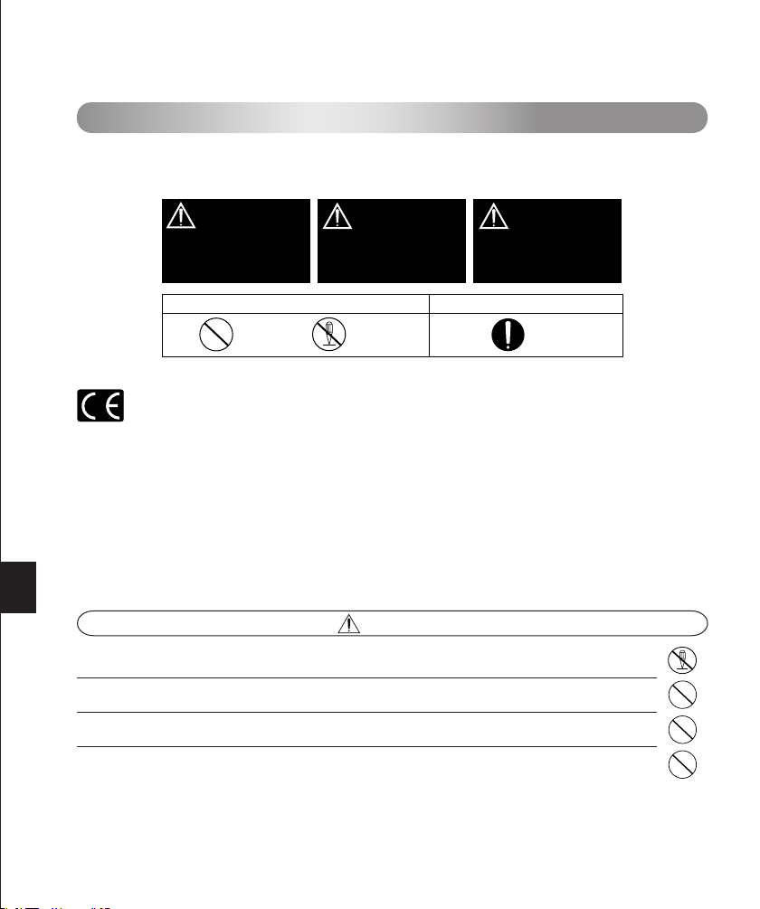
DANGER
Failure to observe the
precautions indicated by this
symbol may result in serious
injury or death.
WARNING
Failure to observe the
precautions indicated by this
symbol may result in injury
or death.
CAUTION
Failure to observe the
precautions indicated by this
symbol may result in injury or
property damage.
Symbols for prohibiting action Symbol instructing action
Prohibited
Disassembly
prohibited
Mandatory
your safety, and keep it handy for future reference.
SAFETY PRECAUTIONS (Be sure to read and observe the following.)
This instruction manual uses a variety of common symbols and icons to assist you in proper handling and usage of this
product, and to warn you of potential hazards to yourself and others as well as to property. These symbols and their
significance are described below.
For customers in Europe
The “CE” mark indicates that this product complies with the European requirements for safety, health, environment and customer protection. CE-mark products are for sale in Europe.
For customers in USA
FCC Notice
This device complies with part 15 of the FCC rules. Operation is subject to the following two conditions:(1) This device may
not cause harmful interference, and (2) this device must accept any interference received, including interference that may
cause undesired operation.
Any unauthorized changes or modifications to this equipment would void the user’s authority to operate.
For customers in CANADA
This Class B digital apparatus complies with Canadian ICES-003.
This Macro Flash System has been designed exclusively for use with Olympus digital cameras. Do not connect the
Macro Flash System to a camera not manufactured by Olympus, as this may result in a malfunction or damage to the
camera and/or Macro Flash System.
DANGER
The Macro Flash System incorporates high-voltage circuitry. Never attempt to disassemble or modify it, as
this may result in electric shock and/or injury.
Do not touch the ring flash connector or twin flash connector terminals on the FC-1 Macro Flash Controller.
Do not use the Macro Flash System where it may be exposed to flammable or explosive gas. Otherwise, fire
ignition or explosion may result.
To prevent a traffic accident, do not direct the flash towards the driver of a car.
2 3
Page 3
WARNING
Do not fire the flash or AF illuminator light immediately in front of a person’s eyes (particularly an infant).
Exposure to the light from the flash at a very short range may cause irreparable injury to the eyes. Be especially careful to avoid using the Macro Flash System at a distance of less than 1 meter from an infant.
Do not leave the Macro Flash System and batteries within reach of children.
• If a child swallows a battery or small accessory, see a doctor immediately.
• If the flash is emitted near a child, their eyes may be injured irreparably.
• Moving parts of the Macro Flash System could injure a child.
Avoid the following actions to prevent fire or injury due to battery fluid leak, overheating, fire ignition or
bursting.
• Do not use batteries that are not specified for use with this Macro Flash System.
• Do not throw the battery in a fire, expose it to heat, short-circuit it, or disassemble it.
• Do not mix old and new batteries, or batteries of different types or brands.
• Do not attempt to recharge non-rechargeable batteries such as alkaline batteries.
• Do not load batteries with the +/– polarity reversed.
Do not store the Macro Flash System in a place exposed to excessive dust or moisture. Otherwise, fire or
electric shock may result.
Do not use the flash when it is covered by a flammable object such as a handkerchief.
Do not touch the light-emitting area after use. It will be very hot and could burn you.
If the Macro Flash System is dropped in water or any fluid gets inside, immediately remove the batteries and
contact your dealer or Olympus. Continued use could result in fire or electric shock.
CAUTION
If you notice any abnormalities such as leakage, discoloration, deformation, overheating, or odor, stop using
this device. Continued use could result in fire, overheating or explosion. Remove the batteries carefully to
avoid burning yourself and to prevent exposure to gas or dangerous fluids that may be released. For repair,
contact Olympus.
Always remove the batteries when you don’t expect to use the Macro Flash System for a long period. Other-
wise, heat generation or fluid leak from the batteries may result in fire, injury and/or contamination of the
surroundings.
Do not use a leaking battery. Doing so could result in fire or electric shock. Please contact your dealer or
Olympus.
Do not handle the Macro Flash System with wet hands. Doing so could result in electric shock.
Do not leave the Macro Flash System in a place where it may be exposed to high temperatures. Otherwise,
deterioration of parts or fire may result.
Do not take out the batteries immediately after using the Macro Flash System continuously for a long period.
Otherwise, the hot batteries may cause burns.
Do not deform the battery compartment or allow any foreign objects to get inside.
Page 4
HANDLING PRECAUTIONS
The Macro Flash System is composed of precision electronic parts. Absolutely avoid using or storing the
Macro Flash System in the following places, as this may result in malfunction or failure.
• Under direct sunlight, on a beach, etc.
• Anywhere exposed to high temperature and humidity or rapid fluctuations in temperature and humidity.
• Any place exposed to excessive sand, dust or dirt.
• Near a fire.
• Near an air conditioner or air humidifier.
• Any place exposed to water or moisture.
• Any place subject to vibrations.
• Inside an automobile.
Do not apply a strong vibration or shock to the Macro Flash System by dropping it or hitting it against
something.
When the Macro Flash System has not been used for a long period, mold or moss may form. This can cause
a malfunction. To prevent this, it is recommended to check the operations before using the Macro Flash
System after a long period of storage.
Do not touch the electric contacts of the Macro Flash System to prevent malfunction.
To prevent overheating and deterioration of the light-emitting section, do not continue full activation more than
40 times in a row. After firing the flash 40 times successively, do not use the flash for at least 10 minutes to
allow the light-emitting section to cool down.
BATTERY PRECAUTIONS
Use only the specified batteries.
• AA (R6) alkaline dry cell batteries (LR6 type) ..................... x 4
• AA (R6) Ni-Cd batteries ...................................................... x 4
• AA (R6) Ni-Mh batteries ..................................................... x 4
• AA (R6) Ni-Mn batteries (ZR6 type) ................................... x 4
• AA (R6) lithium batteries (FR6 type) ................................... x 4
• Lithium battery packs (CR-V3 type) (Olympus LB-01) ....... x 2
* AA (R6) manganese batteries cannot be used.
Be sure to observe the following points. Otherwise, battery fluid leak, overheating, fire ignition and/or bursting
may result.
• Do not mix old and new batteries, recharged and discharged batteries, batteries of different capacities, or
batteries of different types or brands.
• Do not attempt to recharge non-rechargeable batteries such as alkaline batteries.
• Do not load or use the batteries with the +/– polarity reversed. If the batteries do not fit smoothly in the battery
compartment, do not force them.
• Never use a battery if its outer coating (insulation) has been partially or entirely peeled off. Otherwise, leakage, overheating or explosion may result.
• Some brand-new batteries may also have their outer coating (insulation) peeled off completely or partially.
Never use these batteries.
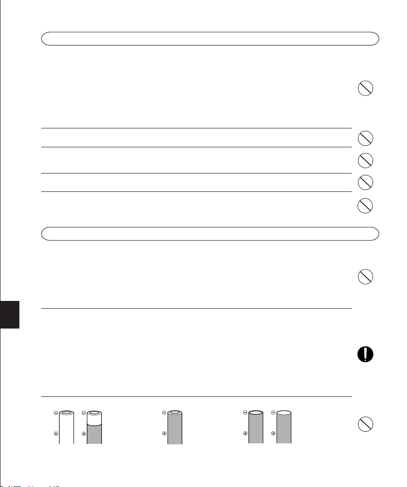
Do not use the following kinds of batteries.
Outer coating (insulation) is peeling or
has peeled off.
The negative end is
slightly swollen and
is not covered by the
coating (insulation).
The negative end is
flat (whether or not a
part of the negative
pole is covered by
the coating).
4 5
Page 5
All rechargeable batteries must be recharged using the specified battery charger, simultaneously and com-
pletely. Be sure to read the battery and battery charger instruction manual.
Improper use of batteries may result in fluid leak, heat generation and/or damage. Sweat and oil smudges
may cause battery contact failure. To prevent this, remove any stain completely with a dry cloth and insert the
batteries by observing the +/– polarity.
In general, battery performance will be temporarily reduced as the ambient temperature drops. When using
batteries in a cold place, keep them warm by keeping the Macro Flash System in cold protection gear or
clothing.
If battery fluid gets on your skin or clothes, it may irritate your skin. Immediately rinse your skin or clothes with
clean water.
If battery fluid comes in contact with your eyes, blindness may result. Rinse your eyes with clean water without
rubbing them and see a doctor immediately.
Do not apply a strong shock to a battery or throw it.
When traveling, it is a good idea to carry spare batteries with you. In some countries, it may be difficult to
obtain certain batteries.
Do not immerse batteries in water or moisten the terminals at its both ends.
If the +/– terminals of a battery are stained with sweat or oil smudges, contact failure may result.
Clean the terminals well with a dry cloth before using the batteries.
Do not throw a battery in fire or heat it.
When disposing of batteries, be sure to follow local regulations.
When disposing of a rechargeable battery, insulate the +/– terminals with pieces of tape and take them to your
nearest rechargeable battery recycling center.
Note on the cameras used with the Macro Flash System
● The functions available from the Macro Flash System are limited with certain digital cameras. For details, please check
the Olympus website (http://www.olympusamerica.com/E1).
Before reading this manual
○ The information in this manual may be subject to change without notice.
○ This manual has been compiled as carefully as possible. However, if you have any questions or wish to report an error
or omission, please contact Olympus.
○ Duplication of this manual in part or in whole without permission of Olympus is prohibited except for personal use.
Reproduction of the contents of this manual without permission of Olympus is strictly prohibited.
○ Olympus will not assume any liability for damages, loss of profit or claims from any third party incurred due to improper
use of this product.
○ Olympus will not assume any liability for damages and loss of profit related to the loss of image data due to a failure of
this product, servicing by a third party not designated by Olympus, or any other reason.
○ Note that the quality of pictures shot with this product differs from the quality of pictures taken with ordinary film-based
cameras.
Tr ademark information
All brand names and product names mentioned in this manual are the trademarks or registered trademarks of their respective owners.
Page 6

CONTENTS
• Macro Flash System ...................................................................................................................... 7
• Checking the Package Contents ................................................................................................... 8
• Applicable Cameras and Lenses ................................................................................................... 9
• Nomenclature .............................................................................................................................. 10
• Case for Macro Flash System ..................................................................................................... 12
• Macro Flash Controller FC-1 ....................................................................................................... 13
Loading batteries ................................................................................................................. 13
Attaching to the camera/Removing from the camera .......................................................... 14
• Ring Flash RF-11 ......................................................................................................................... 15
Attaching to the camera ...................................................................................................... 15
Checking the battery power ................................................................................................ 16
Selecting the control mode .................................................................................................. 18
Using the illuminators ..........................................................................................................19
TTL AUTO ........................................................................................................................... 20
MANUAL ............................................................................................................................. 22
Light control range .............................................................................................................. 24
• Twin Flash TF-22 ......................................................................................................................... 27
Attaching to the camera ...................................................................................................... 27
Checking the battery power ................................................................................................ 29
Selecting the control mode .................................................................................................. 31
Adjusting the firing angle ..................................................................................................... 32
Using the illuminators ..........................................................................................................33
TTL AUTO ........................................................................................................................... 34
MANUAL ............................................................................................................................. 37
Using the diffuser FDT-1 ..................................................................................................... 41
Other operations ................................................................................................................. 41
Light control range .............................................................................................................. 42
• Custom Setup .............................................................................................................................. 46
• All Reset ....................................................................................................................................... 47
• Warning Display List .................................................................................................................... 47
• Continuous Firing ......................................................................................................................... 48
• Optional Accessories ................................................................................................................... 49
• Q&A ............................................................................................................................................. 50
• Main Specifications ...................................................................................................................... 51
6 7
Page 7
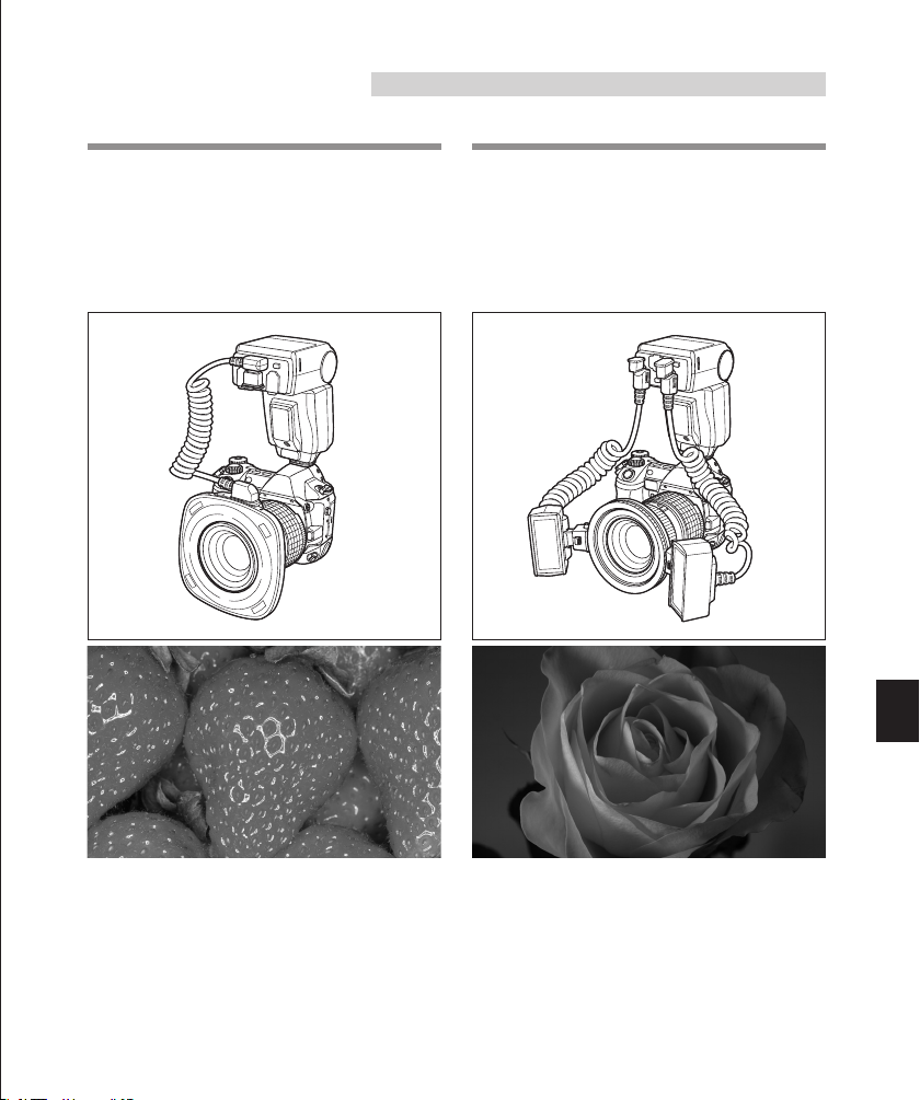
MACRO FLASH SYSTEM
=Ring Flash RF-11 (P.15)
This flash makes it possible to shoot a small
subject without putting a shadow on it. It also
makes possible various shooting techniques
not available with ordinary flashes, such as
close-up shooting in a hole.
=Twin Flash TF-22 (P.27)
This flash employs two flash lamps and allows
more versatile flash activation for macro shooting. For example, you can enhance shading and
depth by varying the firing angles, positions and
Twin Flash light ratio of the two flash lamps. You
can also use just one of the two flash lamps.
The RF-11 Ring Flash and TF-22 must be connected to the FC-1 Macro Flash Controller for use.
When an Olympus Four Thirds System digital SLR camera is used, the TTL AUTO mode can
be used to optimize exposure.
The RF-11 Ring Flash and TF-22 Twin Flash cannot be used simultaneously.
Page 8

CHECKING THE PACKAGE CONTENTS
Check that all of the parts and accessories shown in the following table are included in the package. If any item is missing or damaged, contact your dealer.
Products
Items
Macro Flash Controller FC-1
Ring Flash RF-11
Twin Flash TF-22
Shoe Ring SR-1
Diffuser FDT-1
Macro Flash Case
Instructions (This manual)
Products Available as Sets Products Available Individually
Ring Flash Set
SRF-11
○
○
○
○
Twin Flash Set
STF-22
○
○
○
○
○
○
Items marked ○ are provided with each product.
This instruction manual applies to the SRF-11 and STF-22.
• Ring Flash RF-11
• Macro Flash Controller
FC-1
• Macro Flash Case
Ring Flash
RF-11
○
Twin Flash
TF-22
○
○
○
• Twin Flash TF-22
• Shoe Ring SR-1
• Diffuser FDT-1
8 9
Page 9
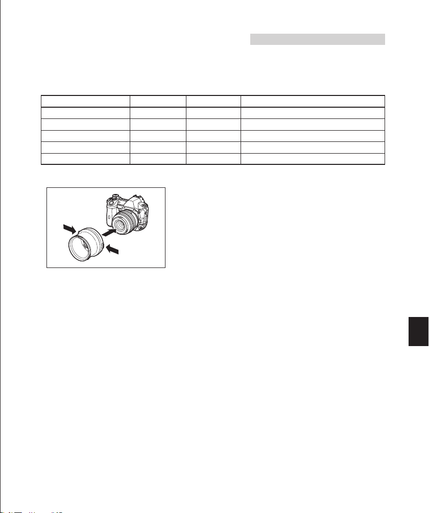
APPLICABLE CAMERAS AND LENSES
Olympus Four Thirds System Digital SLR Camera E-1
The Macro Flash System can be combined with this camera together with one of the Zuiko
digital lenses marked with ○ in the following table.
Zuiko digital lens
ZUIKO DIGITAL ED50mm f2 Macro
ZUIKO DIGITAL 11-22mm f2.8-3.5
ZUIKO DIGITAL 14-54mm f2.8-3.5
ZUIKO DIGITAL ED50-200mm f2.8-3.5
ZUIKO DIGITAL ED300mm f2.8
Ring Flash RF-11
*○
×
○
○
×
Twin Flash TF-22
*○
○
○
○
×
*:
The optional FR-1 Flash Adapter Ring is required
* How to use the FR-1 Flash Adapter Ring
For information on combining these flashes with upcoming Olympus digital cameras and lenses,
check the Olympus website or contact Olympus Customer Support Center.
: Applicable. ×: Not applicable.
○
Remark
.
Page 10
NOMENCLATURE
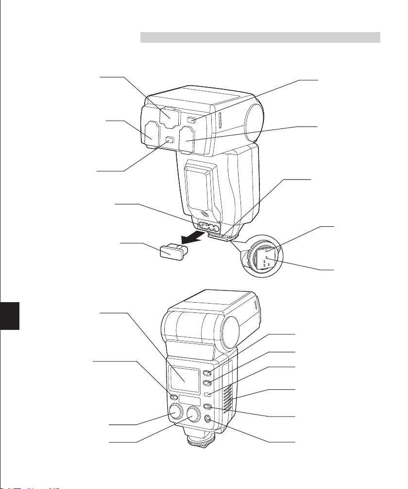
Macro Flash Controller FC-1
Ring Flash connector
(Page 15)
Twin Flash connector
(B) (Page 27)
Twin Flash release
button (Page 28)
External power connector
Connect the optional HV-1
Flash High-Voltage Pack.
Te r minal cover
Control panel
Panel light button
Press to light up the control
panel for about 15 seconds.
The control panel lights up
when controlled by a digital
camera with communication
capability.
Dial A
Ring Flash release
button (Page 15)
Twin Flash connector
(A) (Page 27)
Lock ring
Lock pin
(Page 14)
Electrical contact (Page 14)
Mode button (Pages 18 & 31)
Lamp button (Pages 19 & 33)
Auto Check lamp
(Pages 20 & 34)
Battery compartment cover
(Page 13)
Charge lamp/Test button
(Pages 16 & 29)
Dial B
Power button
10 11
Page 11
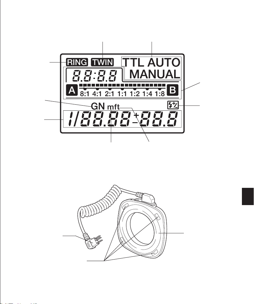
Control Panel Display
Ring Flash
Guide number
(GN)
Setting display
(GN, light intensity
and light intensity
adjustment)
* For simplicity, this figure shows the panel with all indicators lit.
Ring Flash RF-11
Twin Flash Control mode
Meter (Page 46)
Feet (Page 46)
Twin Flash light
ratio display
(Pages 36& 40)
Light intensity
adjustment
(Pages 21, 23,
35 & 39)
Connector terminal
(Page 15)
Light emitting window
Illuminator
(Page 19)
Page 12

Twin Flash TF-22
Diffuser FDT-1
(Page 41)
Diffuser mounting
groove
Tr ipod screw
(Page 41)
Connector terminal (Page 27)
Light emitting
window
Shoe ring mount
(TF-22 flash section)
Illuminator (Page 33)
Tr ipod screw
Mountingring
Release button
(Shoe Ring SR-1)
CASE FOR MACRO FLASH SYSTEM
The semi-hard case can accommodate all of the Macro Flash System components.
Ring Flash RF-11
Macro Flash Controller FC-1
Rotation ring
Rotation lock
button
Shoe frame
Diffuser FDT-1
Twin Flash TF-22
Shoe Ring SR-1
Flash Adapter Ring
FR-1 (optional)
12 13
Page 13
MACRO FLASH CONTROLLER FC-1
<Loading batteries>
Always use one of the following battery combinations
• AA (R6) alkaline dry cell batteries (LR6 type) ...................... x 4
• AA (R6) Ni-Cd batteries ....................................................... x 4
• AA (R6) Ni-Mh batteries ....................................................... x 4
• AA (R6) Ni-Mn batteries (ZR6 type) ..................................... x 4
• AA (R6) lithium batteries (FR6 type) .................................... x 4
• Lithium battery packs (CR-V3 type) (Olympus LB-01) ......... x 2
* AA (R6) manganese batteries cannot be used.
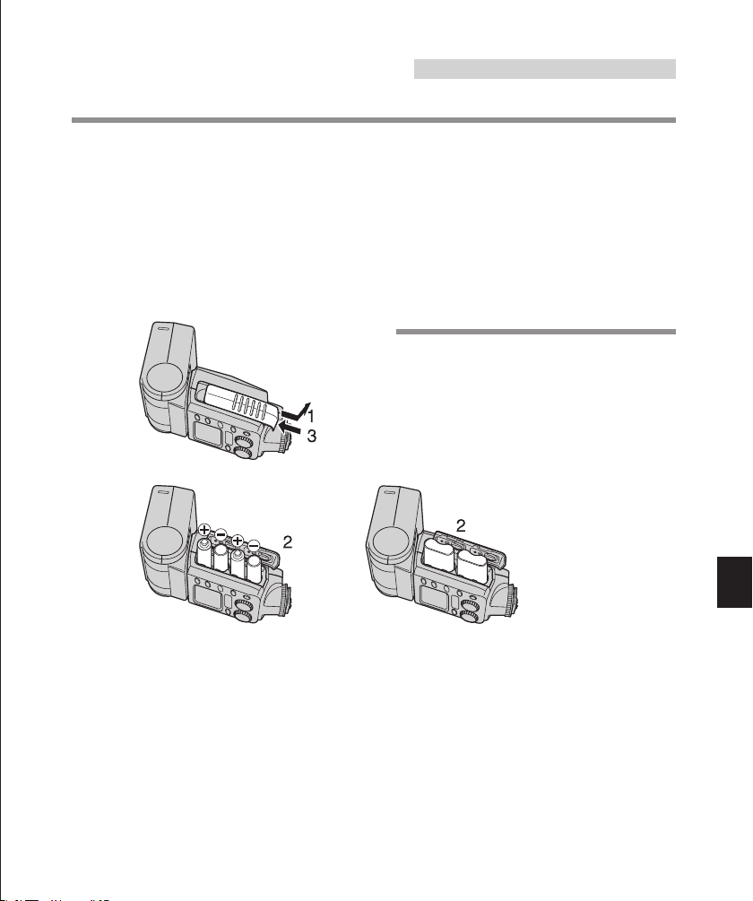
How to load the batteries
1. Open the battery compartment cover.
2. Insert the batteries with correct +/– polarity.
3. Close the battery compartment cover.
AA (R6) type batteries CR-V3
The following product (optional) can also be used as an external power supply (page 49) :
• Flash High-Voltage Set SHV-1
Notes
• Do not mix old and new batteries or batteries of different types.
• Remove the batteries when the Macro Flash Controller is not going to be used for a long period.
• Carry spare batteries when traveling or when using the flash in cold areas.
• If the Power button of the FC-1 Macro Flash Controller is pressed when the RF-11 Ring Flash or TF-22 Twin Flash
is not connected, the [RING] or [TWIN] indicator on the control panel blinks and the Macro Flash Controller turns off
automatically (page 47).
Page 14
<Attaching to the camera/Removing from the camera>
Confirm that both the camera and Macro Flash Controller are off.
Attaching or removing the Macro Flash Controller while either it or the camera is on may result in
malfunction.
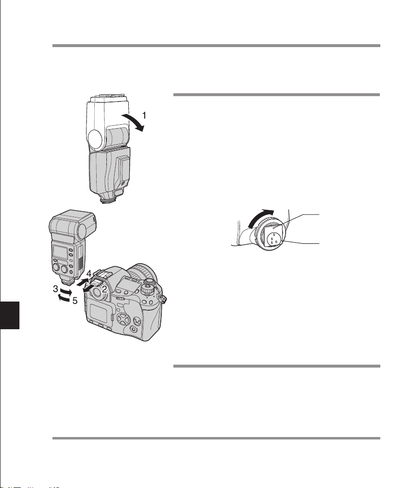
How to attach
1. Place the head section in the standard position (horizon-
tal, front).
2. Remove the hot shoe cover from the camera.
• Store the hot shoe cover in the pocket of the macro flash
case to avoid losing it.
3. Loosen the lock ring.
• If the lock pin is in the out position, put it to the in position by
turning it all the way in the opposite direction to [←LOCK]
until it stops.
• Do not apply excessive force to the lock pin.
• Do not touch the electric contact with a finger or metallic object.
• Do not attach the Macro Flash Controller while the lock pin is in the out
position. Otherwise, malfunction may result.
Lock pin
Electric contact
4. Slide the Macro Flash Controller all the way into the hot
shoe until it clicks and stops.
5. Tu rn the lock ring all the way in the direction of [←LOCK]
until it stops.
How to remove
1. Loosen the lock ring, then slide the Macro Flash Control-
ler out of the hot shoe.
2. Attach the hot shoe cover to the camera.
Attach the RF-11 Ring Flash or TF-22 Twin Flash to the Macro Flash Controller.
• How to use the RF-11 Ring Flash : See page 15.
• How to use the TF-22 Twin Flash : See page 27.
14 15
Page 15

RING FLASH RF-11
<Attaching to the camera>
• Attach the FC-1 Macro Flash Controller to the camera beforehand.
• To prevent the Ring Flash from falling off, attach it with the camera in a stable position.
1. While aligning the indices, attach the RF-11 Ring Flash to
the lens.
2. Press the Ring Flash release button of the FC-1 Macro
Flash Controller to remove the cap.
3. IInsert the RF-11 Ring Flash connector terminal into the
Ring Flash connector on the FC-1 Macro Flash Controller
until it clicks.
• When unplugging the connector, be sure to press and hold
the Ring Flash release button. Be sure to attach the cap
after unplugging the connector.
• Do not pull the cord when plugging or unplugging the connector. Always grasp it by the connector plug. Pulling the
cord could damage the connector wire.
Notes
• Confirm that both the Macro Flash Controller and Ring Flash are off before attaching or removing them. Otherwise,
malfunction may result.
• Be sure to leave the Twin Flash connectors capped. Otherwise, the Macro Flash Controller cannot be turned on.
Memo
The Ring Flash and Twin Flash connector terminals are subject to high voltages. To ensure safety, the Macro Flash
Controller is designed so that it cannot be turned on unless one of the flashes is connected to it and all of its unused
connectors are capped.
Page 16
<Checking the battery power>
MACRO FLASH CONTROLLER
FC-1
MODE
LAMP
AUTO
CHECK
TEST/
CHARGE
POWER
LIGHT
RATIO GN/
MACRO FLASH CONTROLLER
FC-1
MODE
LAMP
AUTO
CHECK
TEST/
CHARGE
POWER
LIGHT
RATIO GN/
MACRO FLASH CONTROLLER
FC-1
MODE
LAMP
AUTO
CHECK
TEST/
CHARGE
POWER
LIGHT
RATIO GN/
MACRO FLASH CONTROLLER
FC-1
MODE
LAMP
AUTO
CHECK
TEST/
CHARGE
POWER
LIGHT
RATIO GN/
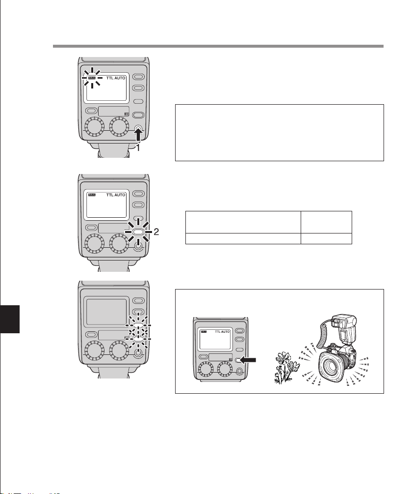
1. Tu rn the camera on and then press the Power button to
2. Ensure that the Charge lamp lights up.
turn the Ring Flash on.
•The [RING] indicator appears on the control panel and
battery charging starts.
Notes:
• If the [RING] or [TWIN] indicator on the control panel
blinks, wait until the blinking stops, then turn the camera
off and re-connect the Ring Flash to the Ring Flash connector (page 47).
• Both Twin Flash connectors must be capped or the Ring Flash
will not turn when the Power button is pressed.
• Replace the batteries if the time taken for the Charge lamp
to light up is longer than the values specified below.
Alkaline, Ni-Mn, lithium or
Ni-Cd batteries
Ni-Mh batteries
30 sec.
10 sec.
• If the Charge lamp and AUTO CHECK lamp blink alternately, it means that the battery capacity is running low. In
this case, replace the batteries.
Memo: Test flash activation
To perform test flash activation, press the Test button.
MACRO FLASH CONTROLLER
FC-1
LIGHT
RATIO GN/
MODE
LAMP
AUTO
CHECK
TEST/
CHARGE
POWER
16 17
Page 17

3. Press the Power button again to turn the Ring Flash off.
MACRO FLASH CONTROLLER
FC-1
MODE
LAMP
AUTO
CHECK
TEST/
CHARGE
POWER
LIGHT
RATIO GN/
Tu rn the Ring Flash off in the following cases:
• Before mounting it on the camera or dismounting it from
the camera.
• When flash emission is not required.
• When not using the Ring Flash.
• When plugging or unplugging the Ring Flash connector.
Flash Interval and Flash Count
The following table shows the flash intervals and flash counts for various batteries. Data is
based on using batteries all of the same type.
Batteries used
AA (R6) alkaline dry cell batteries (LR6 type)
AA (R6) Ni-Cd batteries, 1000 mAh
AA (R6) Ni-Mh batteries, 1900 mAh
AA (R6) Ni-Mn batteries (ZR6 type)
AA (R6) lithium batteries (FR6 type)
Lithium battery packs (CR-V3)
Flash interval
Approx. 4 sec.
Approx. 3 sec.
Approx. 3.5 sec.
Approx. 4 sec.
Approx. 5 sec.
Approx. 4 sec.
* The flash emission interval and count data were obtained from in-house tests at Olympus.
Flash count
Approx. 250 times
Approx. 170 times
Approx. 200 times
Approx. 160 times
Approx. 190 times
Approx. 420 times
Page 18

<Selecting the control mode>
MACRO FLASH CONTROLLER
FC-1
MODE
LAMP
AUTO
CHECK
TEST/
CHARGE
LIGHT
1. Press the Shutter button of the camera gently to start com-
munication of shooting information including ISO speed,
lens iris and shutter speed between the camera and Macro
Flash System.
•The selected flash control mode is shown on the control
panel.
• The mode is switched every time the MODE button is
pressed.
Flash control
mode
TTL AUTO
MANUAL
Notes
• Certain modes may be unavailable depending on the shooting mode set on the camera.
• It is not possible to select an unavailable mode.
Control panel
display
Control operation
Flash is controlled automatically by
performing pre-flash according to
the camera setup.
Flash is performed at the manually
set light intensity
Main applications
Usually use this mode with a digital
camera with communication capability.
Shooting using manual flash.
18 19
Page 19

<Using the illuminators>
The illuminators can be used as indicators for three different functions: modeling, AF, and redeye reduction.
Modeling lamp function
This function makes it easy to confirm subject s in low light.
MACRO FLASH CONTROLLER
FC-1
LIGHT
RATIO GN/
MODE
LAMP
AUTO
CHECK
TEST/
CHARGE
POWER
1. Press the Lamp button to light up the illuminators. The
modeling function is activated.
•The default setting for the illuminator lighting period is 30
seconds.
• The lighting period can be set between 1 second and 3
minutes (page 46).
2. The illuminators turn off either when the camera shutter is
released or the Lamp button is pressed again.
AF Illuminator function
With the Olympus Four Thirds System digital SLR camera, the AF illuminators can be turned on to
facilitate focus adjustment when the subject is dark or lacks contrast.
This function can also be defeated in the Custom Setup operation (page 46).
Red eye reduction lamp function
With the Olympus Four Thirds System digital SLR camera, the illuminators function as red-eye
reduction lamps that light up for about 1 second to minimize red eyes caused by flash emission.
• It takes about 1 second from the time the illuminators light until the camera’s shutter releases.
Hold the camera firmly during this period to prevent image blur.
• The red eye reduction effect may become less obvious when the subject does not look at the
flash directly from the front, the subject does not look at the pre-flash, the subject is located at a
distance or due to individual properties of the subject.
Page 20

<TTL AUTO>
MACRO FLASH CONTROLLER
FC-1
MODE
LAMP
AUTO
CHECK
TEST/
CHARGE
POWER
LIGHT
RATIO GN/
MACRO FLASH CONTROLLER
FC-1
MODE
LAMP
AUTO
CHECK
TEST/
CHARGE
POWER
LIGHT
RATIO GN/
MACRO FLASH CONTROLLER
FC-1
MODE
LAMP
AUTO
CHECK
TEST/
CHARGE
POWER
LIGHT
RATIO GN/
In this mode, pre-flash is performed to measure the optimum flash light intensity and then the
actual flash is emitted.
1. See the following table and set the lens iris (F) according
to the lens in use.
Standard lens iris
Zuiko Digital lenses
ZUIKO DIGITAL ED50mm f2 Macro
ZUIKO DIGITAL 14-54mm f2.8-3.5
ZUIKO DIGITAL ED50-200mm f2.8-3.5
F11
F8
•Even if a different lens iris (F) Is used, optimum flash
exposure is also available provided that it falls within
the light control range of the flash in use.
• The flash’s light control range varies according to the
lens and shooting distance. See page 24 for details.
2. When flash activation has been performed correctly, the
AUTO CHECK lamp blinks for about 5 seconds after
the shutter is released. If the lamp does not blink, the
exposure may be incorrect. In this case, you will need
to adjust shooting settings such as the lens iris (F).
20 21
Page 21

Light intensity adjustment
MACRO FLASH CONTROLLER
FC-1
MODE
LAMP
AUTO
CHECK
TEST/
CHARGE
POWER
LIGHT
RATIO GN/
The flash light intensity can be adjusted between +3 and –3.
The light intensity adjustment must be set to ON in the Custom Setup operation (page 46).
• The indicator appears in the control panel.
1. Tu rn dial B to select a light intensity adjustment value in
the following steps.
(This selection is also possible with dial A.)
0 → +0.3 → +0.7 → +1.0 ... +3.0
0 → –0.3 → –0.7 → –1.0 ... –3.0
Adjustment setting
2. If the camera’s flash adjustment mode is selected, the ac-
tual flash light intensity will be the sum of the light intensity
adjustment value set on the Ring Flash and that set on the
camera.
The light intensity adjustment value displayed on the control panel applies to the Ring Flash only.
[Example]
Adjustment
setting
RF-11 +0.3
Camera +0.3
Light intensity adjustment
display on the control panel
Actual adjustment
value
+0.3 +0.6
Page 22

<MANUAL>
MACRO FLASH CONTROLLER
FC-1
MODE
LAMP
AUTO
CHECK
TEST/
CHARGE
POWER
LIGHT
RATIO GN/
MACRO FLASH CONTROLLER
FC-1
MODE
LAMP
AUTO
CHECK
TEST/
CHARGE
POWER
LIGHT
RATIO GN/
In this mode, the flash is emitted according to the light intensity setting.
1. The control panel shows the light intensity ratio.
Light intensity ratio: Ratio of the current light intensity with
respect to the full flash light intensity.
* The light intensity ratio display can be changed to the guide number
(GN) display in the Custom Setup operation (page 48).
2. Tu rn dial A to set the desired light intensity ratio.
The available light intensity ratios are 1/1, 1/2, 1/4, 1/8,
1/16, 1/32, 1/64, 1/128 and 1/256.
Light intensity setting
Guide numbers (GN) and light intensity ratio
Light intensity ratio
1/1 1/2 1/4 1/8 1/16 1/32 1/64 1/128 1/256
GNm 11 8.0 5.6 4.0 2.8 2.0 1.4 1.0 0.7
GNft 36 26 18 13 9.2 6.6 4.6 3.3 2.3
How to determine the lens iris (F), light intensity or guide number (GN)
Since the distance to the subject is very short and the shooting magnification is very high in
Macro shooting, the light intensity is lower than would normally be the case with the lens iris
(F) setting. This is because the light intensity for the lens iris is based on a distance setting of
infinity.
The F-number at this time Is referred to as the effective F-value, which is variable depending
on the shooting magnification and lens type. In consequence, the above facto should be taken
in consideration when determining the flash light intensity and lens iris in the MANUAL mode.
1.When using an Olympus Four Thirds System SLR camera:
• Check the light control range of the lens used and set the combination of the lens iris (F) and
light intensity ratio according to the shooting distance (page 24).
• If optimum exposure cannot be obtained, take some test shots and adjust the lens iris, light
intensity ratio and other conditions as required.
2.When using any other camera:
•Take some test shots and set the lens iris (F) and light intensity ratio as required.
22 23
Page 23

Light intensity adjustment
MACRO FLASH CONTROLLER
FC-1
MODE
LAMP
AUTO
CHECK
TEST/
CHARGE
POWER
LIGHT
RATIO GN/
The light intensity ratio (guide number) can be adjusted in 1/3-step increments.
The light intensity adjustment must be set to ON in the Custom Setup operation (page 46).
• The indicator appears in the control panel.
1. Tu rn dial B to select a light intensity adjustment value in
the following steps.
0 → +0.3 → +0.7
→
Tu r ning the dial further increases the light intensity ratio.
0 → –0.3 → –0.7
→
Tu r ning the dial further decreases the light intensity ratio.
Light intensity
ratio
Adjustment
setting
2. Even if the camera’s flash adjustment mode is selected, it
will not be applied. Only the adjustment set on the Ring
Flash is applied.
[Example]
Adjustment
setting
RF-11 +0.3
Camera +0.3
Light intensity adjustment
display on the control panel
+0.3 +0.3
Actual adjustment
value
Page 24

< Light control range>
Iris(F)
Shooting
distance
F22
F16
F11
F8
F5.6
F4.0
F2.8
F2
1/4(1/16)
1/8(1/32)
1/16(1/64)
1/32(1/128)
1/64(1/256)
1/128(
−−
)
1/256(
−−
)
1/4(1/16)
1/8(1/32)
1/16(1/64)
1/32(1/128)
1/64(1/256)
1/128(
−−
)
1/256(
−−
)
8m 4m 2m 1m 0.5m 0.24m 23.1cm 21.3cm
Light intensity ratio ISO100 (ISO400)
When EX-25 Extension Tube
is used.
TTL AUTO light control range, with ISO 100
TTL AUTO light control range, with ISO 400
−−
(1/1)−−(1/2)
1/1(1/4)
1/2(1/8)
Iris(F)
Shooting
distance
Iris(F)
Shooting
distance
F22
F16
F11
F8
F5.6
F4.0
F2.8
1/8(1/32)
1/16(1/64)
1/32(1/128)
1/64(1/256)
1/128(
−−
)
1/256(
−−
)
1/8(1/32)
1/16(1/64)
1/32(1/128)
1/64(1/256)
1/128(
−−
)
1/4(1/16)
1/8(1/32)
1/16(1/64)
1/32(1/128)
1/64(1/256)
1/128(
−−
)
8m 4m 2m 1m 0.5m 0.25m 0.22mm
8m 4m 2m 1m 0.5m 0.25m 0.22mm
The EX-25 Extension Tube
cannot be used.
F22
F16
F11
F8
F5.6
F4.0
22.2cm 17.7cm
Light intensity ratio ISO100 (ISO400)
Light intensity ratio ISO100 (ISO400)
TTL AUTO light control range, with ISO 100
TTL AUTO light control range, with ISO 400
TTL AUTO light control range, with ISO 100
TTL AUTO light control range, with ISO 400
When EX-25 Extension Tube
is used.
−−
(1/1)−−(1/2)
1/1(1/4)
1/2(1/8)
1/4(1/16)
−−
(1/1)−−(1/2)
1/1(1/4)
1/2(1/8)
1/4(1/16)
The following charts show the light control range of the RF-11 Ring Flash with each type of lens.
How to read the chart
1.TTL AUTO
Flash at optimum exposure is available by setting the lens iris (F) in the range for each
shooting distance shown in the following charts.
Range with ISO 100 Range with ISO 400
24 25
• Flash at optimum exposure can be obtained by setting the light intensity ratio and lens iris
(F) combination for each shooting distance.
Note
• Since the optimum exposure is variable depending on subject, lighting, distance, etc., it is recommended that you
determine the optimum settings by taking some test shots based on the following charts.
ZUIKO DIGITAL ED50mm f2 Macro
How to see the chart (when the shooting distance is 1 m)
TTL AUTO With ISO 100, iris F2 to F11 (←→) is the range where optimum exposure is achieved.
MANUAL With ISO 100, optimum exposure is achieved at iris F11 (●) when the light intensity
ratio is 1/1.
2.MANUAL
Page 25

ZUIKO DIGITAL 14-54mm f2.8-3.5, At 14 mm
Iris(F)
Shooting
distance
Iris(F)
Shooting
distance
F22
F16
F11
F8
F5.6
F4.0
F2.8
1/8(1/32)
1/16(1/64)
1/32(1/128)
1/64(1/256)
1/128(
−−
)
1/256(
−−
)
1/8(1/32)
1/16(1/64)
1/32(1/128)
1/64(1/256)
1/128(
−−
)
1/4(1/16)
1/8(1/32)
1/16(1/64)
1/32(1/128)
1/64(1/256)
1/128(
−−
)
8m 4m 2m 1m 0.5m 0.25m 0.22mm
8m 4m 2m 1m 0.5m 0.25m 0.22mm
The EX-25 Extension Tube
cannot be used.
F22
F16
F11
F8
F5.6
F4.0
22.2cm 17.7cm
Light intensity ratio ISO100 (ISO400)
Light intensity ratio ISO100 (ISO400)
TTL AUTO light control range, with ISO 100
TTL AUTO light control range, with ISO 400
TTL AUTO light control range, with ISO 100
TTL AUTO light control range, with ISO 400
When EX-25 Extension Tube
is used.
−−
(1/1)−−(1/2)
1/1(1/4)
1/2(1/8)
1/4(1/16)
−−
(1/1)−−(1/2)
1/1(1/4)
1/2(1/8)
1/4(1/16)
ZUIKO DIGITAL 14-54mm f2.8-3.5, At 54 mm
Page 26

ZUIKO DIGITAL ED50-200mm f2.8-3.5, At 50 mm
Iris(F)
Shooting
distance
F22
F16
F11
F8
F5.6
F4.0
F2.8
−−
(1/1)
−−
(1/2)
1/1(1/4)
1/2(1/8)
1/4(1/16)
1/8(1/32)
−−
(1/1)
−−
(1/2)
1/1(1/4)
1/2(1/8)
1/4(1/16)
−−
(1/1)
−−
(1/2)
1/1(1/4)
1/2(1/8)
1/4(1/16)
1/1(1/4)
1/2(1/8)
1/4(1/16)
1/8(1/32)
1/16(1/64)
8m 4m 2m 1.2m
8m 4m 2m 1.2m
Light intensity ratio ISO100 (ISO400)
Light intensity ratio ISO100 (ISO400)
TTL AUTO light control range, with ISO 100
TTL AUTO light control range, with ISO 400
Iris(F)
Shooting
distance
F22
F16
F11
F8
F5.6
F4.0
195.9cm 88.5cm
When EX-25 Extension Tube
is used.
TTL AUTO light control range, with ISO 100
TTL AUTO light control range, with ISO 400
28cm〜27.6cm
When EX-25 Extension Tube
is used.
ZUIKO DIGITAL ED50-200mm f2.8-3.5, At 200 mm
26 27
Page 27

TWIN FLASH TF-22
<Attaching to the camera>
• Attach the FC-1 Macro Flash Controller to the camera beforehand.
1. Attach the SR-1 Shoe Ring (provided) to the lens.
Rotation ring
Release button
Rotation lock button
2. Attach the TF-22 Twin Flash to the shoe frame.
• When removing the Twin Flash, press and hold the release button on the shoe frame.
•To change the positioning of the light-emitting section, press
and hold the rotation lock button while turn the shoe frame.
The position of the light-emitting section can also be changed
Memo:
by turning the rotary ring.
3. Press the FC-1 Macro Flash Controller’s Twin release but-
ton to remove the cap.
Page 28

4. Insert the TF-22 Twin Flash connector terminal into the
MACRO FLASH CONTROLLER
FC-1
MODE
LAMP
AUTO
CHECK
TEST/
CHARGE
POWER
LIGHT
RATIO GN/
MACRO FLASH CONTROLLER
FC-1
MODE
LAMP
AUTO
CHECK
TEST/
CHARGE
POWER
LIGHT
RATIO GN/
MACRO FLASH CONTROLLER
FC-1
MODE
LAMP
AUTO
CHECK
TEST/
CHARGE
POWER
LIGHT
RATIO GN/
MACRO FLASH CONTROLLER
FC-1
MODE
LAMP
AUTO
CHECK
TEST/
CHARGE
POWER
LIGHT
RATIO GN/
Twin Flash connector on the FC-1 Macro Flash Controller
until it clicks.
• When unplugging the connectors, be sure to press and
hold the Twin Flash release button. Be sure to attach the
cap after unplugging the connectors.
• Do not pull the cord when plugging or unplugging the connector. Always grasp it by the connector plug. Pulling the
cord could damage the connector wire.
Notes
• Confirm that both the Macro Flash Controller and Twin Flash are off before attaching and removal. Otherwise,
malfunction may result.
• When using only one flash of the Twin Flash, be sure to cap the unused Twin Flash connector.
Be sure to leave the Ring Flash connector capped. Otherwise, the Macro Flash Controller cannot be turned on.
Memo
The Ring Flash and Twin Flash connector terminals are subject to high voltages. To ensure safety, the Macro Flash
Controller is designed so that it cannot be turned on unless one of the flashes is connected to it and all of its unused
connectors are capped.
28 29
Page 29

<Checking the battery power>
MACRO FLASH CONTROLLER
FC-1
MODE
LAMP
AUTO
CHECK
TEST/
CHARGE
POWER
LIGHT
RATIO GN/
MACRO FLASH CONTROLLER
FC-1
MODE
LAMP
AUTO
CHECK
TEST/
CHARGE
POWER
LIGHT
RATIO GN/
MACRO FLASH CONTROLLER
FC-1
MODE
LAMP
AUTO
CHECK
TEST/
CHARGE
POWER
LIGHT
RATIO GN/
MACRO FLASH CONTROLLER
FC-1
MODE
LAMP
AUTO
CHECK
TEST/
CHARGE
POWER
LIGHT
RATIO GN/
1. Tu rn the camera on and then press the Power button to
2. Ensure that the Charge lamp lights up.
turn the Twin Flash on.
• The [TWIN] indicator appears on the control panel and
battery charging starts.
Notes:
• If the [RING] or [TWIN] indicator on the control panel
blinks, wait until the blinking stops, then turn the camera
off and re-connect the Ring Flash to the Ring Flash connector (page 47).
• If both the RF-11 Ring Flash and TF-22 Twin Flash are connected, the Twin Flash cannot be turned on by pressing its
Power button. (The Ring Flash and Twin Flash cannot be
connected simultaneously.)
• Replace the batteries if the time taken for the Charge lamp
to light up is longer than the values specified below.
Alkaline, Ni-Mn, lithium or
Ni-Cd batteries
Ni-Mh batteries
30 sec.
10 sec.
• If the Charge lamp and AUTO CHECK lamp blink alternately, it means that the battery capacity is running low. In
this case, replace the batteries.
Memo: Test flash activation
To perform test flash activation, press the Test button.
Page 30

3. Press the Power button again to turn the Twin Flash off.
MACRO FLASH CONTROLLER
FC-1
MODE
LAMP
AUTO
CHECK
TEST/
CHARGE
POWER
LIGHT
RATIO GN/
MACRO FLASH CONTROLLER
FC-1
MODE
LAMP
AUTO
CHECK
TEST/
CHARGE
LIGHT
Tu rn the Twin Flash off in the following cases:
• Before mounting it on the camera or dismounting it from
the camera.
• When flash emission is not required.
• When not using the Twin Flash.
• When plugging or unplugging the Twin Flash connectors.
Flash Interval and Flash Count
The following table shows the flash intervals and flash counts for various batteries. Data is
based on using batteries all of the same type.
Batteries used
AA (R6) alkaline dry cell batteries (LR6 type)
AA (R6) Ni-Cd batteries, 1000 mAh
AA (R6) Ni-Mh batteries, 1900 mAh
AA (R6) Ni-Mn batteries (ZR6 type)
AA (R6) lithium batteries (FR6 type)
Lithium battery packs (CR-V3)
Flash interval
Approx. 4 sec.
Approx. 3 sec.
Approx. 3.5 sec.
Approx. 4 sec.
Approx. 5 sec.
Approx. 4 sec.
* The flash emission interval and count data were obtained from in-house tests at Olympus.
Flash count
Approx. 250 times
Approx. 170 times
Approx. 200 times
Approx. 160 times
Approx. 190 times
Approx. 420 times
30 31
Page 31

<Selecting the control mode>
MACRO FLASH CONTROLLER
FC-1
MODE
LAMP
AUTO
CHECK
TEST/
CHARGE
LIGHT
1. Press the Shutter button of the camera gently to start
communication of shooting information including ISO
speed, lens iris and shutter speed between the camera
and Macro Flash System.
• The selected flash control mode is shown on the control
panel.
• The mode is switched every time the MODE button is
pressed.
Flash control
mode
TTL AUTO
MANUAL
Control panel
display
Control operation
Flash is controlled automatically by
performing pre-flash according to
the camera setup.
Flash is performed at the manually
set light intensity
Main applications
Usually use this mode with a digital
camera with communication capability.
Shooting using manual flash.
Notes
• Certain modes may be unavailable depending on the shooting mode set on the camera.
• The [TTL AUTO] mode may be unavailable with some cameras, including cameras with no communication
capability.
• It is not possible to select an unavailable mode.
Page 32

<Adjusting the firing angle> <Using the illuminators>
Index
Up ③
Up ②
Up ①
Horizontal position
Down ①
Down ②
Down ③
Angle of light emitting section
• Adjustment at the following angles is possible in the up-down direction.
Index position
Up ③
Up ②
Up ①
Horizontal position
Down ①
Down ②
Down ③
•
The left-right rotation angle can be adjusted at 45° intervals.
Recommended angles: Angles in which light is illuminated on the subject effectively
Angle from the horizontal position
68°
45°
20°
0°
15°
30°
45°
Left-right rotation angle, from front
Shooting distance*
0.2 m
0.3 m
0.4 m
0.5 m
0.7 m
1.0 m
*
Distance between the CCD position (marked on the
30° downward (Down ② index position)
15° downward (Down ① index position)
20ºupward (Up ① index position)
20ºupward (Up ① index position)
Angle
0°
0°
camera body when you are using the E-1) and the subject.
• If the system is mounted on the shoe frame, the light emitting section faces the shooting
direction when it set at an upward angle of 20° (Up ① index position).
• Shadows are cast differently and the three-dimensional effect varies depending on the angle.
Also, the effect differs according to the lens used. Set the firing angle according to your shooting objective.
• The intensity of the light directed at the subject varies according to the angle.
TTL AUTO Flash is fired at optimum exposure, but the light adjustment range varies depend-
ing on the angle.
MANUAL Set the flash ratio after taking some test shots.
Note
Pointing the light emitting section at the lens causes flares and ghosts.
32 33
Page 33

The illuminators can be used as indicators for three different functions: modeling, AF, and redeye reduction.
Modeling lamp function
This function makes it easy to confirm subject s in low light.
MACRO FLASH CONTROLLER
FC-1
LIGHT
RATIO GN/
MODE
LAMP
AUTO
CHECK
TEST/
CHARGE
POWER
1. Press the Lamp button to light up the illuminators. The
modeling function is activated.
•The default setting for the illuminator lighting period is 30
seconds.
• The lighting period can be set between 1 second and 3
minutes (page 46).
2. The illuminators turn off either when the camera shutter is
released or the Lamp button is pressed again.
AF Illuminator function
With the Olympus Four Thirds System digital SLR camera, the AF illuminators can be turned on
to facilitate focus adjustment when the subject is dark or lacks contrast.
This function can also be defeated in the Custom Setup operation (page 46).
Red eye reduction lamp function
With the Olympus Four Thirds System digital SLR camera, the illuminators function as red-eye
reduction lamps that light up for about 1 second to minimize red eyes caused by flash emission.
• It takes about 1 second from the time the illuminators light until the camera’s shutter releases.
Hold the camera firmly during this period to prevent image blur.
• The red eye reduction effect may become less obvious when the subject does not look at the
flash directly from the front, the subject does not look at the pre-flash, the subject is located at a
distance or due to individual properties of the subject.
Page 34

<TTL AUTO>
MACRO FLASH CONTROLLER
FC-1
MODE
LAMP
AUTO
CHECK
TEST/
CHARGE
POWER
LIGHT
RATIO GN/
MACRO FLASH CONTROLLER
FC-1
MODE
LAMP
AUTO
CHECK
TEST/
CHARGE
POWER
LIGHT
RATIO GN/
MACRO FLASH CONTROLLER
FC-1
MODE
LAMP
AUTO
CHECK
TEST/
CHARGE
POWER
LIGHT
RATIO GN/
In this mode, pre-flash is performed to measure the optimum flash light intensity and then the
actual flash is emitted.
1. See the following table and set the lens iris (F) according
to the lens in use.
Standard lens iris
Zuiko Digital lenses
ZUIKO DIGITAL ED50mm f2 Macro
ZUIKO DIGITAL 11-22mm f2.8-3.5
ZUIKO DIGITAL 14-54mm f2.8-3.5
F11
ZUIKO DIGITAL ED50-200mm f2.8-3.5
•Even if a different lens iris (F) is used, flash at optimum
exposure is also available provided that it falls within the
light control range of the flash.
•Even if a different lens iris (F) Is used, optimum flash exposure is also available provided that it falls within the light
control range of the flash in use.
• The flash’s light control range varies according to the lens
and shooting distance. See page 42 for details.
2. When flash activation has been performed correctly, the
AUTO CHECK lamp blinks for about 5 seconds after the
shutter is released. If the lamp does not blink, the exposure may be incorrect. In this case, you will need to adjust
shooting settings such as the lens iris (F).
34 35
Page 35

Light intensity adjustment
MACRO FLASH CONTROLLER
FC-1
MODE
LAMP
AUTO
CHECK
TEST/
CHARGE
POWER
LIGHT
RATIO GN/
The flash light intensity can be adjusted between +3 and –3.
The light intensity adjustment must be set to ON in the Custom Setup operation (page 46).
• The indicator appears in the control panel.
1. Tu rn dial B to select a light intensity adjustment value in
the following steps.
(This selection is also possible with dial A.)
0 → +0.3 → +0.7 → +1.0 ... +3.0
0 → –0.3 → –0.7 → –1.0 ... –3.0
Adjustment setting
2. The light intensity adjustment value is displayed only when
the value is other than 0.
3. If the camera’s flash adjustment mode is selected, the ac-
tual flash light intensity will be the sum of the light intensity
adjustment value set on the Twin Flash and that set on the
camera.
The light intensity adjustment value displayed on the control panel applies to the Twin Flash only.
[Example]
Adjustment
setting
TF-22 +0.3
Camera +0.3
Light intensity adjustment
display on the control panel
+0.3 +0.6
Actual adjustment
value
Page 36

Twin Flash light ratio setting
MACRO FLASH CONTROLLER
FC-1
MODE
LAMP
AUTO
CHECK
TEST/
CHARGE
POWER
LIGHT
RATIO GN/
MACRO FLASH CONTROLLER
FC-1
MODE
LAMP
AUTO
CHECK
TEST/
CHARGE
POWER
LIGHT
RATIO GN/
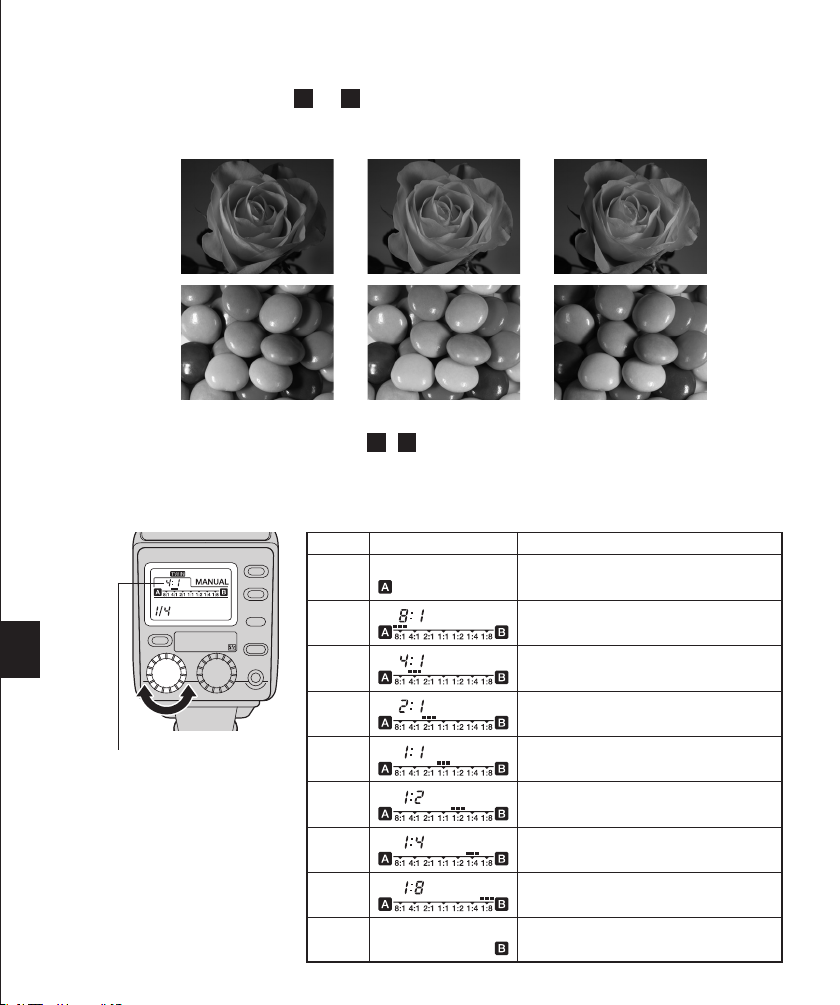
When using both flashes ( A and B ), you can adjust the ratio between their light intensities as required.
This makes it possible to create a three-dimensional effect by applying various degrees of shading to the
subject as shown below.
Light ratio 8 : 1 1 : 1 1 : 8
When dial A is turned, the Twin Flash A / B light ratio is displayed on the control panel. The Twin
Flash light ratio is ready for adjustment.
• The control panel display shows both the light intensity ratio and bar graph simultaneously.
• The setting can be varied in steps of 1/3.
Twin Flash light ratio
Note
In situations where optimum
exposure cannot be obtained
with the selected light ratio
value, the system may automatically change the value
before flash emission.
Light ratio
A
8 : 1
4 : 1
2 : 1
1 : 1
1 : 2
1 : 4
1 : 8
B
Control panel display
Only flash A fires.
Flash B does not fire.
Light ratio 8:1
(Equivalent to +3 steps when converted to
exposure value)
Light ratio 4:1
(Equivalent to +2 steps when converted to
exposure value)
Light ratio 2:1
(Equivalent to +1 steps when converted to
exposure value)
Both flash A and flash B emit light at the same
intensity.
Light ratio 1:2
(Equivalent to –1 steps when converted to
exposure value)
Light ratio 1:4
(Equivalent to –2 steps when converted to
exposure value)
Light ratio 1:8
(Equivalent to –3 steps when converted to
exposure value)
Only flash B fires.
Flash A does not fire.
36 37
Page 37

<MANUAL>
MACRO FLASH CONTROLLER
FC-1
MODE
LAMP
AUTO
CHECK
TEST/
CHARGE
POWER
LIGHT
RATIO GN/
In this mode, the flash is emitted according to the light intensity setting.
1. The control panel shows the light intensity ratio.
When both of the two flashes are used, their combined
light intensity is displayed.
Light intensity ratio: Ratio of the current light intensity with
respect to the full flash light intensity.
* The light intensity ratio display can be changed to the guide number
(GN). display in the Custom Setup operation (page 98).
2. Tu rn dial A to set the desired light intensity ratio.
The available light intensity ratios are 1/1, 1/2, 1/4, 1/8,
Light intensity setting
1/16, 1/32, 1/64, 1/128, 1/256 and 1/512.
• The amount of illumination from the Twin Flash that is applied to the subject varies depending on such conditions
as whether one flash unit is used or two flash units are
used, angle adjustment and light ratio. Set the appropriate
iris (F) or light intensity ratio by referring to the guide number charts.
When using two flashes (Combined guide number)
Light inten-
1/1 1/2 1/4 1/8 1/16 1/32 1/64
sity ratio
GNm 22 16 11 8.0 5.6 4.0 2.8 2.0 1.4 1.0
GNft 72 52 36 26 18 13 9.2 6.6 4.6 3.3
When using only one flash
Light inten-
1/1 1/2 1/4 1/8 1/16 1/32 1/64
sity ratio
GNm 16 11 8.0 5.6 4.0 2.8 2.0 1.4 1.0 0.7
GNft 52 36 26 18 13 9.2 6.6 4.6 3.3 2.3
1/128 1/256 1/512
1/128 1/256 1/512
Page 38

MACRO FLASH CONTROLLER
FC-1
MODE
LAMP
AUTO
CHECK
TEST/
CHARGE
POWER
LIGHT
RATIO GN/
How to determine the lens iris (F), light intensity or guide number (GN)
Since the distance to the subject is very short and the shooting magnification is very high in
Macro shooting, the light intensity is lower than would normally be the case with the lens iris
(F) setting. This is because the light intensity for the lens iris is based on a distance setting of
infinity.
The F-number at this time is referred to as the effective F-value, which is variable depending
on the shooting magnification and lens type. In consequence, the above factor should be
taken in consideration when determining the flash light intensity and lens iris in the MANUAL
mode.
1.When using an Olympus Four Thirds System SLR camera:
• Check the TF-22 Twin Flash light control range diagram for each lens on page 42, and set
the combination of the lens iris (F) and light intensity ratio according to the shooting distance.
• If optimum exposure cannot be obtained, take some test shots and adjust the lens iris, light
intensity ratio and other conditions as required.
2.When using any other camera:
•Take some test shots and set the lens iris (F) and light intensity ratio as required.
38 39
Page 39

Light intensity adjustment
MACRO FLASH CONTROLLER
FC-1
MODE
LAMP
AUTO
CHECK
TEST/
CHARGE
POWER
LIGHT
RATIO GN/
The light intensity ratio (guide number) can be adjusted in 1/3-step increments.
The light intensity adjustment must be set to ON in the Custom Setup operation (page 46).
• The indicator appears in the control panel.
1. Tu rn dial B to select a light intensity adjustment value in
the following steps.
0 → +0.3 → +0.7
→
Tu r ning the dial further increases the light intensity ratio.
0 → –0.3 → –0.7
→
Adjustment setting
Tu r ning the dial further decreases the light intensity ratio.
2. Even if the camera’s flash adjustment mode is selected, it
will not be applied. Only the adjustment set on the Ring
Flash is applied.
[Example]
Adjustment
setting
TF-22 +0.3
Camera +0.3
Light intensity adjustment
display on the control panel
+0.3 +0.3
Actual adjustment
value
Page 40
Twin Flash light ratio setting
MACRO FLASH CONTROLLER
FC-1
MODE
LAMP
AUTO
CHECK
TEST/
CHARGE
POWER
LIGHT
RATIO GN/
When using both flashes ( A and B ), you can adjust the ratio between their light intensities as required.
This makes it possible to create a three-dimensional effect by applying various degrees of shading to the
subject as shown below.
Light ratio 8 : 1 1 : 1 1 : 8
When dial A is turned, the Twin Flash A / B light ratio is displayed on the control panel. The Twin
Flash light ratio is ready for adjustment.
• The control panel display shows both the light intensity ratio and bar graph simultaneously.
• The setting can be varied in steps of 1/3.
Light ratio
Twin Flash light ratio
Note
If the selected Twin Flash light
ratio is too low for the selected
light intensity ratio (guide
number), the Twin Flash light
40 41
ratio display blinks. If this happens, change the Twin Flash
ratio or light intensity ratio
(guide number) (page 46).
A
8 : 1
4 : 1
2 : 1
1 : 1
1 : 2
1 : 4
1 : 8
B
Control panel display
Only flash A fires.
Flash B does not fire.
Light ratio 8:1
(Equivalent to +3 steps when converted to
exposure value)
Light ratio 4:1
(Equivalent to +2 steps when converted to
exposure value)
Light ratio 2:1
(Equivalent to +1 steps when converted to
exposure value)
Both flash A and flash B emit light at the same
intensity.
Light ratio 1:2
(Equivalent to –1 steps when converted to
exposure value)
Light ratio 1:4
(Equivalent to –2 steps when converted to
exposure value)
Light ratio 1:8
(Equivalent to –3 steps when converted to
exposure value)
Only flash B fires.
Flash A does not fire.
Page 41

<Using the diffuser FDT-1>
The diffuser enables shooting under soft lighting by attenuating the shades on the subject.
Another way that shooting options are increased is the ability to use the wide-open iris (F).
1. Insert the diffuser into the diffuser mounting grooves of
the Twin Flash.
• Since the use of the diffuser reduces light intensity by about
2 steps, the guide numbers (GN) change as shown in the
following tables.
TTL AUTO
• Flash at optimum exposure is possible, but the light con-
trol range is reduced due to decrease in the guide number (GN).
MANUAL
•Refer to the following tables when setting the lens iris (F).
When using two flashes (Combined guide number)
Light intensity ratio 1/1 1/2 1/4 1/8 1/16 1/32 1/64 1/128 1/256 1/512
GNm Without diffuser 22 16 11 8.0 5.6 4.0 2.8 2.0 1.4 1.0
With diffuser 11 8.0 5.6 4.0 2.8 2.0 1.4 1.0 0.7 0.5
GNft Without diffuser 72 52 36 26 18 13 9.2 6.6 4.6 3.3
With diffuser 36 26 18 13 9.2 6.6 4.6 3.3 2.3 1.7
When using only one flash
Light intensity ratio 1/1 1/2 1/4 1/8 1/16 1/32 1/64 1/128 1/256 1/512
GNm Without diffuser 16 11 8.0 5.6 4.0 2.8 2.0 1.4 1.0 0.7
With diffuser 8.0 5.6 4.0 2.8 2.0 1.4 1.0 0.7 0.5 0.4
GNft Without diffuser 52 36 26 18 13 9.2 6.6 4.6 3.3 2.3
With diffuser 26 18 13 9.2 6.6 4.6 3.3 2.3 1.7 1.2
<Other operations>
■The tripod screw of the Twin Flash can be used as follows.
• TTL AUTO
Flash at optimum exposure is available but the light control range varies depending on the shooting conditions.
• MANUAL
Set the lens iris (F) by performing test flash activation.
Page 42

< Light control range>
Iris(F)
Shooting
distance
F22
F16
F11
F8
F5.6
F4.0
F2.8
F2
1/16(1/64)
1/32(1/128)
1/64(1/256)
1/128(1/512)
1/256(
−−
)
1/512(
−−−
)
1/16(1/64)
1/32(1/128)
1/64(1/256)
1/128(1/512)
1/256(−−)
1/512(
−−−
)
16m 8m 4m 2m 1m 0.5m 0.24m 23.1cm 21.3cm
Light intensity ratio ISO100 (ISO400)
When EX-25 Extension Tube
is used.
TTL AUTO light control range, with ISO 100
TTL AUTO light control range, with ISO 400
Light control range using one flash unit at 1/512 flash emission ratio with ISO 100
☆:When one flash unit is used (ISO100,1/512)
−−
(1/1)−−(1/2)
1/1(1/4)
1/2(1/8)
1/4(1/16)
1/8(1/32)
Iris(F)
Shooting
distance
F22
F16
F11
F8
F5.6
F4.0
F2.8
1/32(1/128)
1/64(1/256)
1/128(1/512)
1/256(
−−
)
1/512(
−−
)
1/32(1/128)
1/64(1/256)
1/128(1/512)
1/256(
−−
)
1/512(
−−
)
16m 8m 4m 2m 1m 0.5m 0.25m 0.22mm
16m 8m 4m 2m 1m 0.5m 0.25m 0.22mm
Light intensity ratio ISO100 (ISO400)
Light intensity ratio ISO100 (ISO400)
Iris(F)
Shooting
distance
F22
F16
F11
F8
F5.6
F4.0
1/16(1/64)
1/32(1/128)
1/64(1/256)
1/128(1/512)
1/256(
−−
)
1/512(
−−
)
22.2cm 17.7cm
☆:When one flash unit is used (ISO100,1/512)
☆:When one flash unit is used (ISO100,1/512)
When EX-25 Extension Tube
is used.
The EX-25 Extension Tube
cannot be used.
TTL AUTO light control range, with ISO 100
TTL AUTO light control range, with ISO 400
Light control range using one flash unit at 1/512 flash emission ratio with ISO 100
TTL AUTO light control range, with ISO 100
TTL AUTO light control range, with ISO 400
Light control range using one flash unit at 1/512 flash emission ratio with ISO 100
−−
(1/1)
−−
(1/2)
1/1(1/4)
1/2(1/8)
1/4(1/16)
1/8(1/32)
1/16(1/64)
−−
(1/1)−−(1/2)
1/1(1/4)
1/2(1/8)
1/4(1/16)
1/8(1/32)
1/16(1/64)
The following figures show the light control range of the TF-22 Twin Flash with each type of lens.
The figures assume that both flashes are used at the recommended angle (page 32).
1.TTL AUTO
Flash at optimum exposure is available by setting the lens iris (F) in the range for each
shooting distance shown in the following charts.
Range with ISO 100 Range with ISO 400
2.MANUAL
• Flash at optimum exposure can be obtained by setting the light intensity ratio and lens iris
(F) combination for each shooting distance.
Note
• Since the optimum exposure is variable depending on subject, lighting, distance, etc., it is recommended that you
determine the optimum settings by taking some test shots based on the following charts.
ZUIKO DIGITAL ED50mm f2 Macro
42 43
How to see the chart (when the shooting distance is 2 m)
TTL AUTO With ISO 100, iris F2 to F11 (←→) is the range where optimum exposure is achieved.
MANUAL With ISO 100, optimum exposure is achieved at iris F11 (●) when the light intensity
ratio is 1/1.
Page 43

ZUIKO DIGITAL 14-54mm f2.8-3.5, At 14 mm
Iris(F)
Shooting
distance
F22
F16
F11
F8
F5.6
F4.0
F2.8
1/32(1/128)
1/64(1/256)
1/128(1/512)
1/256(
−−
)
1/512(
−−
)
1/32(1/128)
1/64(1/256)
1/128(1/512)
1/256(
−−
)
1/512(
−−
)
16m 8m 4m 2m 1m 0.5m 0.25m 0.22mm
16m 8m 4m 2m 1m 0.5m 0.25m 0.22mm
Light intensity ratio ISO100 (ISO400)
Light intensity ratio ISO100 (ISO400)
Iris(F)
Shooting
distance
F22
F16
F11
F8
F5.6
F4.0
1/16(1/64)
1/32(1/128)
1/64(1/256)
1/128(1/512)
1/256(
−−
)
1/512(
−−
)
22.2cm 17.7cm
☆:When one flash unit is used (ISO100,1/512)
☆:When one flash unit is used (ISO100,1/512)
When EX-25 Extension Tube
is used.
The EX-25 Extension Tube
cannot be used.
TTL AUTO light control range, with ISO 100
TTL AUTO light control range, with ISO 400
Light control range using one flash unit at 1/512 flash emission ratio with ISO 100
TTL AUTO light control range, with ISO 100
TTL AUTO light control range, with ISO 400
Light control range using one flash unit at 1/512 flash emission ratio with ISO 100
−−
(1/1)
−−
(1/2)
1/1(1/4)
1/2(1/8)
1/4(1/16)
1/8(1/32)
1/16(1/64)
−−
(1/1)−−(1/2)
1/1(1/4)
1/2(1/8)
1/4(1/16)
1/8(1/32)
1/16(1/64)
ZUIKO DIGITAL 14-54mm f2.8-3.5, At 54 mm
Page 44

ZUIKO DIGITAL ED50-200mm f2.8-3.5, At 50 mm
Iris (F)
Shooting
distance
F22
F16
F11
F8
F5.6
F4.0
F2.8
1/16(1/64)
1/32(1/128)
1/64(1/256)
1/128(1/512)
1/256(
−−
)
1/512(
−−
)
1/16
(1/64)
1/32(1/128)
1/64(1/256)
1/128(1/512)
1/256(
−−
)
16m 8m 4m 2m 1m 0.5m 0.25m
16m 8m 4m 2m 1m 0.5m 0.28m
Light intensity ratio ISO100 (ISO400)
Light intensity ratio ISO100 (ISO400)
Iris (F)
Shooting
distance
F22
F16
F11
F8
F5.6
F4.0
☆: When one flash unit is used (ISO100, 1/512)
TTL AUTO light control range, with ISO 100
TTL AUTO light control range, with ISO 400
The EX-25 Extension Tube
cannot be used.
The EX-25 Extension Tube
cannot be used.
TTL AUTO light control range, with ISO 100
TTL AUTO light control range, with ISO 400
Light control range using one flash unit at 1/512 flash emission ratio with ISO 100
−−
(1/1)−−(1/2)
1/1(1/4)
1/2(1/8)
1/4(1/16)
1/8(1/32)
−−
(1/1)−−(1/2)
1/1(1/4)
1/2(1/8)
1/4(1/16)
1/8(1/32)
Iris(F)
Shooting
distance
F22
F16
F11
F8
F5.6
F4.0
F2.8
1/1
(1/4)
1/2(1/8)
1/4(1/16)
1/8(1/32)
1/16(1/64)
1/32(1/128)
1/1(1/4)
1/2(1/8)
1/4(1/16)
1/8(1/32)
1/16(1/64)
1/1(1/4)
1/2(1/8)
1/4(1/16)
1/8(1/32)
1/16(1/64)
1/4(1/16)
1/8(1/32)
1/16(1/64)
1/32(1/128)
1/64(1/256)
16m 8m 4m 2m 1.2m
16m 8m 4m 2m 1.2m
Light intensity ratio ISO100 (ISO400)
Light intensity ratio ISO100 (ISO400)
TTL AUTO light control range, with ISO 100
TTL AUTO light control range, with ISO 400
Iris(F)
Shooting
distance
F22
F16
F11
F8
F5.6
F4.0
195.9cm 88.5cm
When EX-25 Extension Tube
is used.
TTL AUTO light control range, with ISO 100
TTL AUTO light control range, with ISO 400
28cm - 278.6cm
When EX-25 Extension Tube
is used.
−−
(1/1)−−(1/2)
−−
(1/1)−−(1/2)
−−
(1/2)
ZUIKO DIGITAL ED50-200mm f2.8-3.5, At 200 mm
44 45
Page 45

ZUIKO DIGITAL 11-22mm f2.8-3.5, At 11 mm
Iris (F)
Shooting
distance
F22
F16
F11
F8
F5.6
F4.0
F2.8
1/16(1/64)
1/32(1/128)
1/64(1/256)
1/128(1/512)
1/256(
−−
)
1/512(
−−
)
1/16
(1/64)
1/32(1/128)
1/64(1/256)
1/128(1/512)
1/256(
−−
)
16m 8m 4m 2m 1m 0.5m 0.25m
16m 8m 4m 2m 1m 0.5m 0.28m
Light intensity ratio ISO100 (ISO400)
Light intensity ratio ISO100 (ISO400)
Iris (F)
Shooting
distance
F22
F16
F11
F8
F5.6
F4.0
☆: When one flash unit is used (ISO100, 1/512)
TTL AUTO light control range, with ISO 100
TTL AUTO light control range, with ISO 400
The EX-25 Extension Tube
cannot be used.
The EX-25 Extension Tube
cannot be used.
TTL AUTO light control range, with ISO 100
TTL AUTO light control range, with ISO 400
Light control range using one flash unit at 1/512 flash emission ratio with ISO 100
−−
(1/1)−−(1/2)
1/1(1/4)
1/2(1/8)
1/4(1/16)
1/8(1/32)
−−
(1/1)−−(1/2)
1/1(1/4)
1/2(1/8)
1/4(1/16)
1/8(1/32)
ZUIKO DIGITAL 11-22mm f2.8-3.5, At 22 mm
Page 46

CUSTOM SETUP
MACRO FLASH CONTROLLER
FC-1
MODE
LAMP
AUTO
CHECK
TEST/
CHARGE
POWER
LIGHT
RATIO GN/
MACRO FLASH CONTROLLER
FC-1
MODE
LAMP
AUTO
CHECK
TEST/
CHARGE
POWER
LIGHT
RATIO GN/
Custom setup allows each user to customize flash setup to suit his or her preferences.
Setup procedure
1. Tu rn the Macro Flash Controller on.
2. Press and hold the MODE button for more than 2 sec-
onds, until the setup mode display appears in the control
panel.
3. Tu rn dial A to select the setup mode.
4. Tu rn dial B to select the value.
5. Press the MODE button to exit from setup and return to
the previous control panel display.
Setup mode
Mode display
Dial A
Value display
Dial B
Function Default
AF illuminator is activated according to the control
AF illuminator
lamp
LAMP timer
Light intensity
adjustment
〜
from the camera.
AF illuminator is defeated.
The lighting time of the modeling lamp can be set.
Selectable time: 1" (1 sec.) ~ 10", 15", 20", 25", 30",
40", 50", 60" and – –" (3 min.)
Light intensity cannot be adjusted.
Light intensity can be adjusted.
A
30"
OFF
The light intensity in MANUAL mode is displayed in
terms of light intensity ratio.
The light intensity in MANUAL mode is displayed in
terms of guide number.
Guide numbers are displayed in meters.
Guide numbers are displayed in feet.
OFF
m
Guide number
display
Guide number
Unit of distance
• Custom setup can be performed separately for the Ring Flash (RING) and Twin Flash (TWIN).
46 47
Page 47

ALL RESET
MACRO FLASH CONTROLLER
FC-1
MODE
LAMP
AUTO
CHECK
TEST/
CHARGE
POWER
LIGHT
RATIO GN/
All Reset resets the custom setups to the factory default settings.
• Press the MODE and LIGHT buttons simultaneously for 2 or
more seconds to reset the custom setups (except for the
distance display unit (m/ft)) to the default settings.
• The distance display unit (m/ft) is not altered by the all reset
operation.
• Restore the Ring Flash (RING) and Twin Flash (TWIN) modes
respectively.
WARNING DISPLAY LIST
Warning details Control panel display Remedy
The Ring Flash or Twin Flash
is not connected.
• The display disappears automatically in
about 4 seconds. When the display has disappeared, connect the Ring Flash or Twin
Flash.
Connection failure during or
connector disconnection during power ON.
The Twin Flash light ratio is
improper.
• Flash emission with the selected light ratio is not possible in Manual mode.
• The display disappears automatically in
about 4 seconds.
• When the display has disappeared, re-connect the Ring Flash or Twin Flash.
•Set the proper Twin Flash light ratio or light
intensity ratio.
Page 48

CONTINUOUS FIRING
Continuous firing makes the light-emitting section hot and may cause it to deteriorate or malfunction. Therefore, continuous firing should be limited to the counts shown in the following tables. Do
not use the Macro Flash System for at least 10 minutes after continuous firing up to the limit count.
Limit counts of continuous firings
Limit count
Ring Flash RF-11 40 times
Limit count
Twin Flash TF-22 40 times
48 49
Page 49

OPTIONAL ACCESSORIES
Shoe adapter ring
External power supplies
• Flash Adapter Ring FR-1
Mounting adapter for use with a Zuiko Digital
ED50mmf2.0Macro lens for Olympus Four Thirds System
digital cameras.
• Flash High Voltage Set SHV-1
(Includes the HV-1 High Voltage Pack, BN-1 Ni-Mh Battery Pack and AC-2 AC Adapter.)
The included BN-1 Ni-Mh battery pack makes it possible
to charge the flash faster and increase the available flash
emission count.
Batteries used in FC-1
AA (R6) alkaline batteries
• Flash emission interval and count data obtained from in-house tests at Olympus.
Battery used in HV-1 Flash interval Flash count
BN-1 Approx. 1 sec. Approx. 750 times
None Approx. 1.2 sec. Approx. 420 times
Note
Up to 40 successive full flashes are permitted. To allow the light-emitting surface to cool, the flash should not be
used for at least 10 minutes after 10 flashes have been fired. See page 48 for details.
Page 50

Q&A
Q The FC-1 cannot be turned on.
A It cannot be turned on in the following cases.
• When the connector(s) for the unused flash (either the Ring Flash or Twin Flash) is not
capped.
• When both the Ring Flash and Twin Flash are connected.
Q Is multi-flash shooting possible in the TTL AUTO mode?
A No, it is not possible.
Q Why does the flash get hot after successive firing?
A The batteries generate heat when flash firing is repeated successively. In this case, use the
flash at intervals until the light-emitting section and batteries cool down.
Q Why can’t I mount the FC-1 on the camera?
A It cannot be mounted if the lock pin is in the out position. If this is the case, turn the lock ring all
the way in the opposite direction to [fl LOCK] until it stops. Once the lock pin is in the in
position, you can mount the FC-1 on the camera (page 14).
Q Why doesn’t the control mode change when I press the MODE button?
A When the Macro Flash System is connected to certain types of communication-capable cam-
era, the flash control mode may only be controlled from the camera.
Q What is the recommended white balance setting for the camera when using the flash?
A The auto white balance mode is recommended. If you use the manual white balance mode,
set the color temperature to 5500K. Note that the color temperature varies depending on the
flash shooting conditions.
Q When the Olympus E-1 Four Thirds System digital camera enters the sleep mode, the FC-1’s
control panel display turns off. Is this normal?
A Ye s, it is normal. When the E-1 enters the sleep mode, so does the FC-1. When the camera
wakes up, so does the FC-1.
Q Does the FC-1 also turn off when the Olympus E-1 digital camera is turned off?
A When the Olympus E-1 Four Thirds System digital camera is turned off, the FC-1 enters the
sleep mode. When the E-1 is turned on again, the FC-1 also turns on. When you want to turn
off the FC-1, turn off the FC-1 before turning off the E-1. In addition, when connected to a
camera without communication capability, the FC-1 enters the sleep mode if it is not operated
for about 60 minutes.
50 51
Page 51

MAIN SPECIFICATIONS
Macro Flash Controller FC-1
Model Number : FS-FC1
Type : External flash controller for digital still camera
Light-emitting device
Auto power OFF :
Illuminator : Automatic firing at low intensity, possible only when a camera with com-
Standard effective distance:0.2 to 3 m (0.7 to 9.9 ft) (Variable depending on the camera and lens in use.)
Power supply : AA (R6) alkaline dry cell batteries (LR6) x 4,
External power supply:Flash High Voltage Set SHV-1 (optional)
Dimensions : 78(W) x 141(H) x 119(D) mm (3.1 x 5.6 x 4.7 in.) (excluding protrusions)
Weight : 320 g (11.3 oz) (excluding batteries)
Operating environment
Ring Flash RF-11
Model Number : FS-RF11
Type : External flash for digital still camera
Guide numbers : TTL AUTO : 11
Firing angle : 80°
Flash emission period
Flash emission count
Recharge time : Approx. 4 seconds (using the AA (R6) alkaline manganese batteries) or
(From full flash activation to
lighting of Charge lamp)
Flash modes : TTL AUTO and MANUAL
Illuminator : 4 lamps built in.
Lens mount : Bayonet
Cable length : Approx. 100 mm (3.9 in)
Dimensions : 120(W) x 135.5(H) x 24(D) mm (4.7 x 5.3 x 0.9 in.) (excluding cable)
Weight : 145 g (5.1 oz)
Operating environment
Humidity : No more than 80% (without condensation).
: Ring Flash RF-11 or Twin Flash TF-22, exchangeable.
Interlocks with the auto power OFF operation of a camera with communication capability.
munication capability is connected.
AA (R6) Ni-Cd batteries x 4,
AA (R6) Ni-Mh batteries x 4,
AA (R6) Ni-Mn batteries (ZR6) x 4,
AA (R6) lithium batteries (FR6) x 4 or
3 V lithium battery pack (Olympus LB-01) x 2
:Temperature: 0 to 40°C (32 to 104°F).
Humidity: No more than 80% (without condensation).
MANUAL : 0.7 to 11
: Approx. 1/560 sec.
: Approx. 250 times (using the LR6-type AA (R6) alkaline dry cell batter-
ies) or approx. 420 times (using the LB-01 lithium battery packs). (Variable depending on shooting conditions)
approx. 4 seconds times (using the LB-01 lithium battery packs).
:Temperature: 0 to 40°C (32 to 104°F).
Page 52

Twin Flash TF-22
Model Number : FS-TF22
Type : External flash for digital still camera
Guide numbers : Full flash activation: 22 (using 2 flashes) or 16 (using 1 flash).
Minimum flash activation : 1.0 (using 2 flashes) or 0.7 (using 1 flash).
MANUAL flash activation : 1.0 to 22 (using 2 flashes) or 0.7 to 16 (using 1 flash).
Firing angle : Using 1 flash: Up-down 50°, left-right 55°
Flash emission period
Flash emission count
Recharge time : Approx. 4 seconds (using the AA (R6) alkaline manganese batteries) or
(From full flash activation to
lighting of Charge lamp)
Flash modes : TTL AUTO and MANUAL
Illuminator : 4 lamps built in per flash.
Lens mount : Shoe Ring SR-1 (provided, filter thread diameter 67 mm / 72 mm)
Cable length : Approx. 100 mm (3.9 in)
<Light emitting section>
Dimensions :
Weight : 105 g (3.7 oz) (using 1 flash)
<Shoe Ring SR-1>
Dimensions : 146.5 (W) x 100 (H) x 22.5 (D) mm (5.8 x 3.9 x 0.9 in)
Weight : 95 g (3.4 oz)
Operating environment
Humidity : No more than 80% (without condensation).
Specifications are subject to change without any notice or obligation on the part of the
manufacturer.
: Approx. 1/1250 sec.
: Approx. 250 times (using the LR6-type AA (R6) alkaline dry cell batter-
ies) or approx. 420 times (using the LB-01 lithium battery packs). (Variable depending on shooting conditions)
approx. 4 seconds (using the LB-01 lithium battery packs).
73 (W) x 50 (H) x 39 (D) mm (2.9 x 2.0 x 1.5 in) (using 1 flash, excluding cable)
:Temperature: 0 to 40°C (32 to 104°F).
52
Technical Support (USA)
24/7 online automated help: http://www.olympusamerica.com/E1
Phone customer : Tel.1-800-260-1625 (Toll-free)
Our phone customer support is available from 8 am to
10 pm (Monday to Friday) ET
E-Mail : e-slrpro@olympusamerica.com
European technical Customer Support
Please visit our homepage http://www.olympus-europa.com
or call NUMBER : Tel.00800-67 10 83 00 (Toll-free)
+49(0)1805-67 10 83 or +49(0)40-23 77 38 99 (Charged)
Page 53

 Loading...