


EPOCH 6LT
Ultrasonic Flaw Detector
User’s Manual
DMTA-10083-01EN — Rev. 3
June 2017
This instruction manual contains essential information on how to use this Olympus product safely and effectively.
Before using this product, thoroughly review this instruction manual. Use the product as instructed.
Keep this instruction manual in a safe, accessible location.

Olympus Scientific Solutions Americas, 48 Woerd Avenue, Waltham, MA 02453, USA
Copyright © 2017 by Olympus. All rights reserved. No part of this publication may be
reproduced, translated, or distributed without the express written permission of Olympus.
This document was prepared with particular attention to usage to ensure the accuracy of the
information contained therein, and corresponds to the version of the product manufactured
prior to the date appearing on the title page. There could, however, be some differences
between the manual and the product if the product was modified thereafter.
The information contained in this document is subject to change without notice.
Part number: DMTA-10083-01EN
Rev. 3
June 2017
Printed in the United States of America
All brands are trademarks or registered trademarks of their respective owners and third
party entities.

DMTA-10083-01EN, Rev. 3, June 2017
Table of Contents
List of Abbreviations ...................................................................................... vii
Labels and Symbols ........................................................................................... 1
Important Information — Please Read Before Use ..................................... 5
Intended Use .......................................................................................................................... 5
Instruction Manual ................................................................................................................ 5
Instrument Compatibility ..................................................................................................... 6
Repair and Modification ....................................................................................................... 6
Safety Symbols ....................................................................................................................... 7
Safety Signal Words ............................................................................................................... 7
Note Signal Words ................................................................................................................. 8
Safety ....................................................................................................................................... 8
Warnings ................................................................................................................................. 9
Battery Precautions .............................................................................................................. 10
Equipment Disposal ............................................................................................................ 11
CE (European Community) ............................................................................................... 11
WEEE Directive .................................................................................................................... 11
China RoHS .......................................................................................................................... 11
Korea Communications Commission (KCC) ................................................................... 13
EMC Directive Compliance ................................................................................................ 13
FCC (USA) Compliance ...................................................................................................... 13
ICES-001 (Canada) Compliance ........................................................................................ 14
Warranty Information ......................................................................................................... 14
Technical Support ................................................................................................................ 15
Introduction ...................................................................................................... 17
1. Package Content ......................................................................................... 19
Table of Contents iii

DMTA-10083-01EN, Rev. 3, June 2017
1.1 Unpacking the Instrument ....................................................................................... 19
1.2 Case Contents ............................................................................................................ 19
1.3 EPOCH 6LT Flaw Detector Components .............................................................. 20
1.4 Standard Accessories ................................................................................................ 21
1.4.1 Battery .............................................................................................................. 21
1.4.2 AC Charger/Adaptor ..................................................................................... 21
1.4.3 USB Data Cable .............................................................................................. 23
1.4.4 USB Drive ........................................................................................................ 23
1.5 Optional Accessories ................................................................................................ 23
1.5.1 Charging Base ................................................................................................. 24
1.5.2 Battery Conditioning ..................................................................................... 25
2. Overview ..................................................................................................... 27
2.1 External Connectors .................................................................................................. 27
2.1.1 AC Adaptor Connector ................................................................................. 28
2.1.2 LEMO Transducer Connectors ..................................................................... 28
2.2 Battery Compartment ............................................................................................... 28
2.3 Data Port ..................................................................................................................... 29
2.3.1 Digital Video Connector ................................................................................ 30
2.3.2 USB A Connector ........................................................................................... 30
2.3.3 Mini USB connector ....................................................................................... 30
2.3.4 Reset Switch .................................................................................................... 30
2.3.5 Accessory Mount ............................................................................................ 30
2.3.6 Wrist Strap Mounts ........................................................................................ 31
2.4 Keys, Knob, and Indicators ...................................................................................... 31
2.4.1 Power Key ....................................................................................................... 32
2.4.2 Power Indicator .............................................................................................. 32
2.4.3 Shift Key .......................................................................................................... 32
2.4.4 Escape Key ...................................................................................................... 33
2.4.5 Enter Key ......................................................................................................... 33
2.4.6 Tab Key ............................................................................................................ 33
2.4.7 Adjustment Knob ........................................................................................... 33
3. Operation ..................................................................................................... 35
3.1 Turning On the Instrument ...................................................................................... 35
3.2 Turning Off the Instrument ..................................................................................... 35
3.3 Connecting the AC Charger/Adaptor .................................................................... 36
3.4 Opening the Data Port Cover .................................................................................. 37
4. Maintenance and Troubleshooting ........................................................ 39
4.1 Battery Replacement ................................................................................................. 39
Table of Contents
iv

DMTA-10083-01EN, Rev. 3, June 2017
4.2 Instrument Cleaning ................................................................................................. 42
4.3 Seal Verification ......................................................................................................... 42
4.4 Display Protection .................................................................................................... 42
4.5 Annual Calibration ................................................................................................... 42
4.6 Troubleshooting ........................................................................................................ 43
Appendix A: Specifications ........................................................................... 45
Appendix B: Parts List ..................................................................................... 49
List of Figures ................................................................................................... 51
List of Tables ..................................................................................................... 53
Index ................................................................................................................... 55
Table of Contents
v

DMTA-10083-01EN, Rev. 3, June 2017
Table of Contents
vi

DMTA-10083-01EN, Rev. 3, June 2017
List of Abbreviations
EFUP environment-friendly use period
IP International Protection (or ingress protection)
Li-ion lithium-ion
UI user interface
WEEE waste electrical and electronic equipment
List of Abbreviations vii

DMTA-10083-01EN, Rev. 3, June 2017
List of Abbreviations
viii
DMTA-10083-01EN, Rev. 3, June 2017
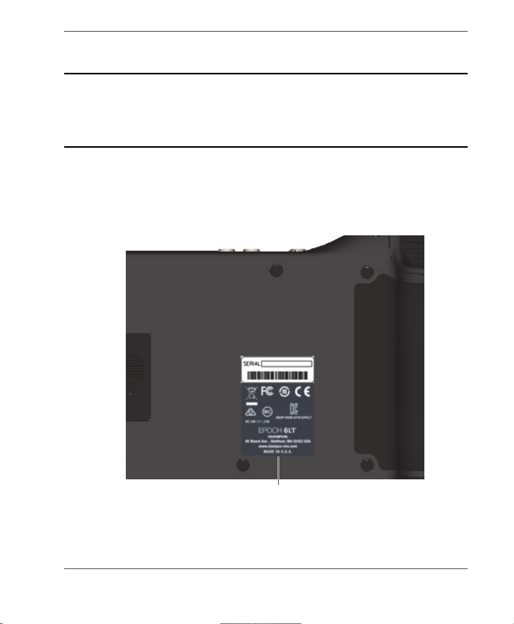
Location of the rating label (see Table 1 on page 2)
Labels and Symbols
A safety-related label and symbols are attached to the EPOCH 6LT at the location
shown in Figure i-1 on page 1. If the label or symbols are missing or illegible, please
contact Olympus.
Figure i‑1 Label location
Labels and Symbols
1
DMTA-10083-01EN, Rev. 3, June 2017
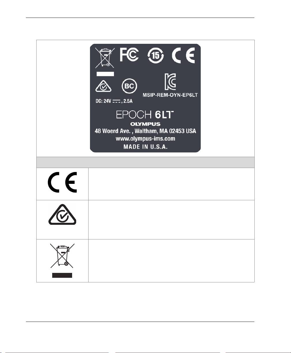
The CE marking is a declaration that this product conforms to
all the applicable directives of the European Community. See
the Declaration of Conformity for details. Contact your Olympus
representative for more information.
Table 1 Contents of the rating label
Contents
Labels and Symbols
2
The regulatory compliance mark (RCM) label indicates that
the product complies with all applicable standards, and has
been registered with the Australian Communications and
Media Authority (ACMA) for placement on the Australian
market.
The WEEE symbol indicates that the product must not be
disposed of as unsorted municipal waste, but should be
collected separately.
DMTA-10083-01EN, Rev. 3, June 2017
Table 1 Contents of the rating label (continued)
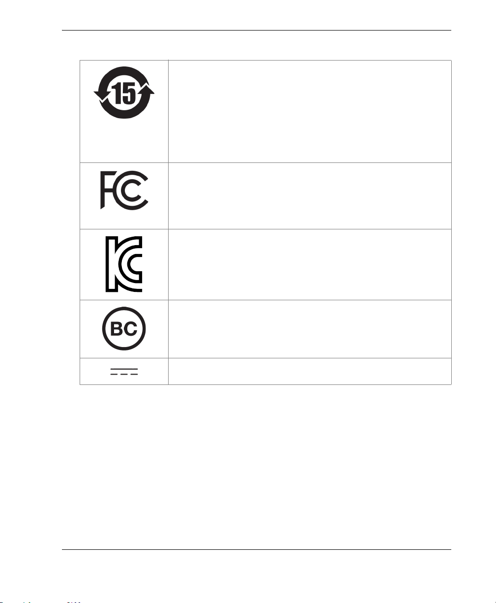
The China RoHS mark indicates the product’s EnvironmentFriendly Use Period (EFUP). The EFUP is defined as the
number of years for which listed controlled substances will not
leak or chemically deteriorate while in the product. The EFUP
for the EPOCH 6LT has been determined to be 15 years. Note:
The Environment-Friendly Use Period (EFUP) is not meant to
be interpreted as the period assuring functionality and
product performance.
This device complies with Part 15 of the FCC Rules. Operation
is subject to the following two conditions: (1) this device may
not cause harmful interference, and (2) this device must accept
any interference received, including interference that may
cause undesired operation.
Seller and user shall be noticed that this equipment is suitable
for electromagnetic equipment for office work (class A) and it
can be used outside home.
The MSIP code for the EPOCH 6LT is the following: MSIPREM-OYN-EP6LT.
Efficiency of battery chargers specific to California, USA.
The direct current symbol.
Labels and Symbols
3
DMTA-10083-01EN, Rev. 3, June 2017
yynnnddmm
CAUTION
Warning symbol
LEMO connectors
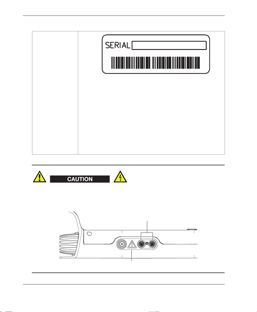
Table 1 Contents of the rating label (continued)
SERIAL
The serial number is a nine (9) digit number in the following
format:
where:
For example, the 080011612 serial number indicates that the
first unit (001) was produced on the December 16, 2008.
yynnnddmm
yy Production year
nnn Unit number manufactured that day
dd Production day
mm Production Month
To avoid the risk of electric shock, do not touch the inner conductors of the LEMO
connectors. Up to 400 V can be present on each inner conductor. The warning symbol
shown in the figure below warns of this electric shock risk.
Labels and Symbols
4
DMTA-10083-01EN, Rev. 3, June 2017
WARNING
Important Information — Please Read Before Use
Intended Use
The EPOCH 6LT is designed to perform nondestructive inspections on industrial and
commercial materials.
Do not use the EPOCH 6LT for any purpose other than its intended use. It must never
be used to inspect or examine human or animal body parts.
Instruction Manual
This instruction manual contains essential information on how to use this Olympus
product safely and effectively. Before using this product, thoroughly review this
instruction manual. Use the product as instructed.
Keep this instruction manual in a safe, accessible location.
Important Information — Please Read Before Use
5
DMTA-10083-01EN, Rev. 3, June 2017
IMPORTANT
CAUTION
CAUTION
Some of the details of components and/or software images in this manual may differ
from your instrument’s components or software display. However, the principles
remain the same.
Instrument Compatibility
The EPOCH 6LT is primarily a self-contained unit. However, it does have a series of
I/O ports that can be used to connect compatible peripherals and connect it to a PC.
The unit derives its required DC input power from the EPOCH 6LT AC adaptor or
battery pack.
Always use equipment and accessories that meet Olympus specifications. Using
incompatible equipment could cause equipment malfunction and/or damage, or
human injury.
Repair and Modification
The EPOCH 6LT does not contain any user-serviceable parts. Opening the instrument
might void the warranty.
In order to prevent human injury and/or equipment damage, do not disassemble,
modify, or attempt to repair the instrument.
Important Information — Please Read Before Use
6
DMTA-10083-01EN, Rev. 3, June 2017
DANGER
WARNING
Safety Symbols
The following safety symbols might appear on the instrument and in the instruction
manual:
General warning symbol
This symbol is used to alert the user to potential hazards. All safety messages that
follow this symbol shall be obeyed to avoid possible harm or material damage.
Shock hazard caution symbol
This symbol is used to alert the user to potential electric shock hazards. All safety
messages that follow this symbol shall be obeyed to avoid possible harm.
Safety Signal Words
The following safety symbols might appear in the documentation of the instrument:
The DANGER signal word indicates an imminently hazardous situation. It calls
attention to a procedure, practice, or the like that if not correctly performed or
adhered to will result in death or serious personal injury. Do not proceed beyond a
DANGER signal word until the indicated conditions are fully understood and met.
The WARNING signal word indicates a potentially hazardous situation. It calls
attention to a procedure, practice, or the like that if not correctly performed or
adhered to could result in death or serious personal injury. Do not proceed beyond a
WARNING signal word until the indicated conditions are fully understood and met.
Important Information — Please Read Before Use
7
DMTA-10083-01EN, Rev. 3, June 2017
CAUTION
IMPORTANT
NOTE
TIP
The CAUTION signal word indicates a potentially hazardous situation. It calls
attention to a procedure, practice, or the like that if not correctly performed or
adhered to may result in minor or moderate personal injury, material damage,
particularly to the product, destruction of part or all of the product, or loss of data. Do
not proceed beyond a CAUTION signal word until the indicated conditions are fully
understood and met.
Note Signal Words
The following symbols could appear in the documentation of the instrument:
The IMPORTANT signal word calls attention to a note that provides information that
is important or essential to the completion of a task.
The NOTE signal word calls attention to an operating procedure, practice, or the like
that requires special attention. A note also denotes related parenthetical information
that is useful but not imperative.
The TIP signal word calls attention to a type of note that helps you apply the
techniques and procedures described in the manual to your specific needs or that
provides hints on how to effectively use the capabilities of the product.
Safety
Before turning on the instrument, verify that the correct safety precautions have been
taken (see the following warnings). In addition, note the external markings on the
instrument, which are described under “Safety Symbols.”
Important Information — Please Read Before Use
8
DMTA-10083-01EN, Rev. 3, June 2017
WARNING
CAUTION
Warnings
General Warnings
• Carefully read the instructions contained in this instruction manual prior to
turning on the instrument.
• Keep this instruction manual in a safe place for further reference.
• Follow the installation and operation procedures.
• It is imperative to respect the safety warnings on the instrument and in this
instruction manual.
• If the equipment is used in a manner not specified by the manufacturer, the
protection provided by the equipment could be impaired.
• Do not install substitute parts or perform any unauthorized modification to the
instrument.
• Service instructions, when applicable, are for trained service personnel. To avoid
the risk of electric shock, do not perform any work on the instrument unless
qualified to do so. For any problem or question regarding this instrument, contact
Olympus or an authorized Olympus representative.
• Do not touch the connectors directly by hand. Otherwise, a malfunction or electric
shock may result.
• Do not allow metallic or foreign objects to enter the device through connectors or
any other openings. Otherwise, a malfunction or electric shock may result.
If an unauthorized power supply cord is used to power the instrument or charge the
batteries, Olympus cannot guarantee the electrical safety of the equipment.
Important Information — Please Read Before Use
9

DMTA-10083-01EN, Rev. 3, June 2017
CAUTION
Battery Precautions
• Before disposing of a battery, check your local laws, rules, and regulations, and
follow them accordingly.
• Transportation of lithium-ion batteries is regulated by the United Nations under
the United Nations Recommendations on the Transport of Dangerous Goods. It is
expected that governments, intergovernmental organizations, and other
international organizations shall conform to the principles laid down in these
regulations, thus contributing to worldwide harmonization in this field. These
international organizations include the International Civil Aviation organization
(ICAO), the International Air Transport Association (IATA), the International
Maritime Organization (IMO), the US Department of Transportation (USDOT),
Transport Canada (TC), and others. Please contact the transporter and confirm
current regulations before transportation of lithium-ion batteries.
• Do not open, crush, or perforate batteries; doing so could cause injury.
• Do not incinerate batteries. Keep batteries away from fire and other sources of
extreme heat. Exposing batteries to extreme heat (over 80 °C) could result in an
explosion or personal injury.
• Do not drop, hit, or otherwise abuse a battery, as doing so could expose the cell
contents, which are corrosive and explosive.
• Do not short-circuit the battery terminals. A short circuit could cause injury and
severe damage to a battery making it unusable.
• Do not expose a battery to moisture or rain; doing so could cause an electric
shock.
• Only use the EPOCH 6LT unit or an external charger approved by Olympus to
charge the batteries.
• Only use batteries supplied by Olympus.
• Do not store batteries that have less than 40 % remaining charge. Recharge
batteries to between 40 % and 80 % capacity before storing them.
• During storage, keep the battery charge between 40 % and 80 %.
• Do not leave batteries in the EPOCH 6LT unit during instrument storage.
Important Information — Please Read Before Use
10
DMTA-10083-01EN, Rev. 3, June 2017
Equipment Disposal
Before disposing of the EPOCH 6LT, check your local laws, rules, and regulations,
and follow them accordingly.
CE (European Community)
This device complies with the requirements of both directive
2014/30/EU concerning electromagnetic compatibility and directive
2014/35/EU concerning low voltage. The CE marking indicates
compliance with the above directives.
WEEE Directive
In accordance with European Directive 2012/19/EU on Waste Electrical
and Electronic Equipment (WEEE), this symbol indicates that the
product must not be disposed of as unsorted municipal waste, but
should be collected separately. Refer to your local Olympus distributor
for return and/or collection systems available in your country.
China RoHS
China RoHS is the term used by industry generally to describe legislation
implemented by the Ministry of Information Industry (MII) in the People’s Republic
of China for the control of pollution by electronic information products (EIP).
Important Information — Please Read Before Use 11

DMTA-10083-01EN, Rev. 3, June 2017
The China RoHS mark indicates the product’s EnvironmentFriendly Use Period (EFUP). The EFUP is defined as the number of
years for which listed controlled substances will not leak or
chemically deteriorate while in the product. The EFUP for the
EPOCH 6LT has been determined to be 15 years.
Note: The Environment-Friendly Use Period (EFUP) is not meant
to be interpreted as the period assuring functionality and product
performance.
“ 中国 RoHS” 是一个工业术语,一般用于描述中华人民共和国信息工业部 (MII)针
对控制电子信息产品 (EIP)的污染所实行的法令。
中国 RoHS 标识是根据 “ 电器电子产品有害物质限制使用管理办
法 ” 以及 “ 电子电气产品有害物质限制使用标识要求 ” 的规定,适
用于在中国销售的电气电子产品上的电气电子产品有害物质限制使
用标识。
电气电子产品
有害物质
限制使用标识
注意:电气电子产品有害物质限制使用标识内的数字为在正常的使
用条件下有害物质不会泄漏的年限,不是保证产品功能性的年限。
产品中有害物质的名称及含量
有害物质
部件名称 铅及其
化合物
(Pb) (Hg) (Cd)
机构部件
主体 光学部件
电气部件
附件
本表格依据 SJ/T 11364 的规定编制。
○:表示该有害物质在该部件所有均质材料中的含量均在 GB/T26572 规定的限量要求以下。
×:表示该有害物质至少在该部件的某一均质材料中的含量超出 GB/T26572 规定的限量要求。
Important Information — Please Read Before Use
12
× ○○○○○
× ○○○○○
× ○○○○○
× ○○○○○
汞及其
化合物
镉及其
化合物
六价铬及
其化合物
(Cr( Ⅵ ))
多溴联苯 多溴
(PBB) (PBDE)
二苯醚

DMTA-10083-01EN, Rev. 3, June 2017
Korea Communications Commission (KCC)
이 기기는 업무용 환경에서 사용할 목적으로 적합성평가를 받은 기기로서 가
정용 환경에서 사용하는 경우 전파간섭의 우려가 있습니다 .
EMC Directive Compliance
This equipment generates and uses radio-frequency energy and, if not installed and
used properly (that is, in strict accordance with the manufacturer’s instructions), may
cause interference. The EPOCH 6LT has been tested and found to comply with the
limits for an industrial device in accordance with the specifications of the EMC
directive.
FCC (USA) Compliance
This device complies with Part 15 of the FCC Rules. Operation is subject to the
following two conditions:
1. This device may not cause harmful interference.
2. This device must accept any interference received, including interference that
may cause undesired operation.
Changes or modifications not expressly approved by the party responsible for
compliance could void the user’s authority to operate the equipment.
This equipment has been tested and found to comply with the limits for a Class A
digital device, pursuant to Part 15 of the FCC Rules. These limits are designed to
provide reasonable protection against harmful interference when the equipment is
operated in a commercial environment. This equipment generates, uses, and can
radiate radio frequency energy, and if not installed and used in accordance with the
instruction manual, might cause harmful interference to radio communications.
Operation of this equipment in a residential area is likely to cause harmful
interference, in which case you will be required to correct the interference at your own
expense.
Important Information — Please Read Before Use 13

DMTA-10083-01EN, Rev. 3, June 2017
ICES-001 (Canada) Compliance
This Class A digital apparatus complies with Canadian ICES-001.
Cet appareil numérique de la classe A est conforme à la norme NMB-001 du Canada.
Warranty Information
Olympus guarantees your Olympus product to be free from defects in materials and
workmanship for a specific period, and in accordance with conditions specified in the
Olympus Scientific Solutions Americas Inc. Terms and Conditions available at
http://www.olympus-ims.com/en/terms/.
The Olympus warranty only covers equipment that has been used in a proper
manner, as described in this instruction manual, and that has not been subjected to
excessive abuse, attempted unauthorized repair, or modification.
Inspect materials thoroughly on receipt for evidence of external or internal damage
that might have occurred during shipment. Immediately notify the carrier making the
delivery of any damage, because the carrier is normally liable for damage during
shipment. Retain packing materials, waybills, and other shipping documentation
needed in order to file a damage claim. After notifying the carrier, contact Olympus
for assistance with the damage claim and equipment replacement, if necessary.
This instruction manual explains the proper operation of your Olympus product. The
information contained herein is intended solely as a teaching aid, and shall not be
used in any particular application without independent testing and/or verification by
the operator or the supervisor. Such independent verification of procedures becomes
increasingly important as the criticality of the application increases. For this reason,
Olympus makes no warranty, expressed or implied, that the techniques, examples, or
procedures described herein are consistent with industry standards, nor that they
meet the requirements of any particular application.
Olympus reserves the right to modify any product without incurring the
responsibility for modifying previously manufactured products.
Important Information — Please Read Before Use
14

DMTA-10083-01EN, Rev. 3, June 2017
Technical Support
Olympus is firmly committed to providing the highest level of customer service and
product support. If you experience any difficulties when using our product, or if it
fails to operate as described in the documentation, first consult the user’s manual, and
then, if you are still in need of assistance, contact our After-Sales Service. To locate the
nearest service center, visit the Service Centers page at: http://www.olympusims.com.
Important Information — Please Read Before Use 15

DMTA-10083-01EN, Rev. 3, June 2017
Important Information — Please Read Before Use
16

DMTA-10083-01EN, Rev. 3, June 2017
Introduction
The EPOCH 6LT is a portable ultrasonic nondestructive testing (NDT) instrument
designed primarily for inspections requiring high portability, such as rope access, and
detection of flaw conditions in welds, pipes, turbine blades, and other structural and
industrial materials. The instrument can be used both indoors and outdoors.
The EPOCH 6LT offers advanced conventional ultrasonic performance featuring a
large dynamic range and superior measurement resolution. The full color liquidcrystal display provides a resolution of 640 × 480 pixels with transflective technology
for superior visibility. The software user interface (UI) provides an intuitive way to
access the full functionality of the instrument.
Before you operate the EPOCH 6LT, Olympus recommends that you have a thorough
understanding of the principles and limitations of ultrasonic nondestructive testing
and that you seek adequate training. Olympus assumes no responsibility for incorrect
operational procedure or misinterpretation of test results.
Although the EPOCH 6LT continuously self-calibrates, you must be aware of the
regulatory requirements. Olympus offers calibration and documentation services.
Contact Olympus or your local representative with any special requests.
Introduction 17

DMTA-10083-01EN, Rev. 3, June 2017
18
Introduction

DMTA-10083-01EN, Rev. 3, June 2017
1. Package Content
A complete EPOCH 6LT package consists of a handheld ultrasonic flaw detector and
several key accessories.
1.1 Unpacking the Instrument
The EPOCH 6LT ultrasonic flaw detector and accessories are shipped in an industrial
transport case.
To unpack the instrument
1. Open the transport case, then locate the shipping papers, documentation, and
USB drive, and then remove them from the case.
2. Remove the EPOCH 6LT and all of the accessories.
3. Inspect the EPOCH 6LT and all accessories for damage, and report any problems
to Olympus immediately.
1.2 Case Contents
The EPOCH 6LT comes standard with several key accessories:
• AC charger/adaptor with power cord (varies by outlet configuration)
• EPOCH 6LT Ultrasonic Flaw Detector Getting Started Guide
• USB drive containing the EPOCH 6LT Ultrasonic Flaw Detector User’s Manual
•USB cable
• Wrist strap
For a complete parts list, see “EPOCH 6LT basic kit” on page 49.
Package Content 19

DMTA-10083-01EN, Rev. 3, June 2017
①
②
③
④
⑤
⑥
⑦
⑧
⑨⑩⑪
⑫
⑬
1.3 EPOCH 6LT Flaw Detector Components
The following table lists the EPOCH 6LT ultrasonic flaw detector components (see
Table 2 on page 20).
Table 2 EPOCH 6LT ultrasonic flaw detector components
Component key EPOCH 6LT — All models
EPOCH 6LT (front)
1 Adjustment knob
2 User interface display
3 Tab button
4 Enter button
5 Escape button
6 Shift (2nd function) button
7Power indicator
8 Power button
EPOCH 6LT (top)
9 Data Port access cover
10 Transducer connectors
11 AC adaptor connector (12 VDC)
EPOCH 6LT (bottom)
12 Battery compartment cover
13 Accessory mount
20
Chapter 1

DMTA-10083-01EN, Rev. 3, June 2017
1.4 Standard Accessories
The EPOCH 6LT comes with the following standard accessories:
• Lithium-ion (Li-ion) battery
• AC power adaptor
• USB data cable
• USB drive containing the user documentation.
1.4.1 Battery
The EPOCH 6LT comes standard with one removable lithium-ion (Li-ion) battery (see
Figure 1-1 on page 21).
Figure 1‑1 EPOCH 6LT Li‑ion battery
1.4.2 AC Charger/Adaptor
The AC charger/adaptor (see Figure 1-2 on page 22) can be used to power the
EPOCH 6LT when an AC mains outlet is available. The AC charger/adaptor is for
indoor use only. If a Li-ion battery is installed in the instrument, and the AC
charger/adaptor is connected, the battery charges until full.
Package Content 21

DMTA-10083-01EN, Rev. 3, June 2017
Figure 1‑2 AC charger/adaptor
Region specific power cords are available for use with the AC charger/adaptor (see
Figure 1-2 on page 22). Make sure that the power cord included with your
EPOCH 6LT is appropriate for your region. See Table 3 on page 22 for more
information.
22
Table 3 Region specific power cord options
Region Plug U8 Number
Australia Type I U8840005
Brazil Type J U8769007
China Type I U8769008
Denmark Type K U8840011
European Type F U8840003
Italy Type L U8840009
Japan Type B U8767383
South Africa, Hong Kong, India, Pakistan Type D/M U8840013
South Korea Type F U8769009
Chapter 1

DMTA-10083-01EN, Rev. 3, June 2017
Mini USB B connector
USB A connector
Table 3 Region specific power cord options (continued)
Region Plug U8 Number
UK Type G U8840007
USA Type B U8840015
1.4.3 USB Data Cable
The EPOCH 6LT flaw detector comes standard with one USB data cable. This cable
provides you the ability to connect the EPOCH 6LT to a PC and transfer information
into or out of the instrument (see Figure 1-3 on page 23). The USB data cable must
have one L20 ferrite bead on each end of the cable to be CE compliant.
Figure 1‑3 USB data cable
1.4.4 USB Drive
The EPOCH 6LT comes standard with a USB drive that is loaded with the
EPOCH 6LT Ultrasonic Flaw Detector User’s Manual. The USB drive can also be used to
store test data.
1.5 Optional Accessories
The optional accessories for the EPOCH 6LT are the following:
Package Content 23

DMTA-10083-01EN, Rev. 3, June 2017
①
• External charging base
• Display protectors (10 pack)
• Rope access accessory kit
• Chest harness
• Desktop stand
For a complete list of the optional accessories, see “EPOCH 6LT optional accessories”
on page 49.
1.5.1 Charging Base
The external charging base charges a Li-ion battery that has been removed from the
EPOCH 6LT. The charging base is useful if you usually operate the EPOCH 6LT
without connecting the AC charger/adaptor. See Table 4 on page 24 for a list of the
charging base’s components.
Table 4 EPOCH 6LT charging base
Component key EPOCH 6LT — All models
Charging base (back)
1Input power socket (12VDC)
24
Chapter 1

DMTA-10083-01EN, Rev. 3, June 2017
②
③④
IMPORTANT
Table 4 EPOCH 6LT charging base (continued)
Component key EPOCH 6LT — All models
Charging base (top)
2 Charging base receptacle
3 Battery charging indicator
4 Battery conditioning button and
discharge indicator
To operate the charging base
1. Plug the AC charger/adaptor into the charging base’s input power socket.
2. Align the Li-ion battery contacts with the contacts at the bottom of the charging
base receptacle.
3. Firmly insert the Li-ion battery into the charging base receptacle.
Do not force the Li-ion battery into the charging base receptacle. Make sure that the
battery contacts and receptacle contacts are properly aligned.
4. Leave the Li-ion battery in the charging base until the charging indicator changes
from flashing green to steady green.
1.5.2 Battery Conditioning
You can condition the Li-ion battery to restore it to peak efficiency. Battery
conditioning completely discharges the battery, then recharges it.
Package Content 25

DMTA-10083-01EN, Rev. 3, June 2017
To condition the battery
1. Firmly insert the battery into the charging base receptacle.
2. Press and hold the battery conditioning button for three seconds (see Table 4 on
page 24).
After you release the button, the blue discharge indicator begins flashing.
3. Leave the battery in the charging base during the entire discharge/charge cycle:
a) The discharge indicator flashes blue until the battery is fully discharged.
b) The charging indicator flashes green until the battery is fully charged.
c) The charging indicator glows steady green when the discharge/charge cycle is
complete.
26
Chapter 1

DMTA-10083-01EN, Rev. 3, June 2017
LEMO connectors
AC charger/adaptor connector
2. Overview
The EPOCH 6LT ultrasonic flaw detector has a complement of connections intended
to maximize the usability of the instrument.
2.1 External Connectors
The external connectors are located at the top of the instrument (see Figure 2-1 on
page 27).
Figure 2‑1 External connectors
Overview 27

DMTA-10083-01EN, Rev. 3, June 2017
NOTE
Receive connector
Transmit connector
2.1.1 AC Adaptor Connector
The AC charger/adaptor connects to the AC adaptor connector of the EPOCH 6LT to
power the instrument and charge the battery.
2.1.2 LEMO Transducer Connectors
The EPOCH 6LT is supplied with sealed LEMO 00 transducer connectors. A center
pin automatically identifies the connected transducer with certain Olympus corrosion
dual element transducers.
The transducer connectors are color coded red and blue. When used with dual
element transducers and in through-transmission modes, the red LEMO 00 connector
acts as the transmit connector and the blue LEMO 00 connector acts as the receive
connector.
For single crystal pulse-echo inspections, you must connect the transducer to the red
LEMO 00 (transmit) connector to send and receive a signal.
Figure 2‑2 Color‑coded LEMO connectors
2.2 Battery Compartment
The battery compartment cover is located at the bottom of the instrument (see
Figure 2-3 on page 29).
Chapter 2
28

DMTA-10083-01EN, Rev. 3, June 2017
Battery compartment
Battery compartment cover
USB A connector
Reset switch
Mini USB B connectorDigital Video connector
Figure 2‑3 Battery compartment—cover closed
A sliding latch button opens the battery compartment cover and ensures the door is
sealed when closed.
2.3 Data Port
The data port contains the EPOCH 6LT digital I/O connections and reset switch.
Figure 2‑4 Data port connectors and reset switch
Overview 29

DMTA-10083-01EN, Rev. 3, June 2017
Accessory mount point
2.3.1 Digital Video Connector
The Digital Video connector is used to connect the EPOCH 6LT to an external digital
display via a compatible cable (optional). The Digital Video cable must have one L20
ferrite bead on each end of the cable to be CE compliant.
2.3.2 USB A Connector
The USB A connector is used to connect the EPOCH 6LT to a USB storage device. The
USB A connector must be used with the Olympus USB drive or equivalent to be CE
compliant.
2.3.3 Mini USB connector
The mini USB connector is used to connect the EPOCH 6LT, via the supplied USB
cable, to a PC for data transfer.
2.3.4 Reset Switch
The Reset switch is used to reset the system software in the event of a catastrophic
software failure.
2.3.5 Accessory Mount
The accessory mount is a standard ¼ in.-20 thread insert, which is located on the
bottom of the instrument (see Figure 2-5 on page 30). Multiple mechanical accessories
can be used with this mount, including the Olympus rope access accessory kit.
Figure 2‑5 Accessory mount
Chapter 2
30

DMTA-10083-01EN, Rev. 3, June 2017
Wrist strap mount
Wrist strap mount
2.3.6 Wrist Strap Mounts
The wrist strap mounts are located on the handle of the instrument (see Figure 2-6 on
page 31). The EPOCH 6LT ships with the wrist strap mounted.
Figure 2‑6 Wrist strap mounts
2.4 Keys, Knob, and Indicators
The keys and indicators are located on the front of the instrument. The adjustment
knob is located on the left side of the instrument.
Overview 31

DMTA-10083-01EN, Rev. 3, June 2017
Figure 2‑7 EPOCH 6LT front panel
2.4.1 Power Key
The Power key ( ) is used to turn on or off the instrument.
2.4.2 Power Indicator
The power indicator ( ) glows when power is applied to the instrument.
2.4.3 Shift Key
The Shift key ( ) is used to activate the second function, changing the way the
ESC, Enter, and Tab keys function.
Chapter 2
32

DMTA-10083-01EN, Rev. 3, June 2017
2.4.4 Escape Key
The ESC key ( ) is used to move the focus to the previous data field in the user
interface (UI). The ESC > Shift key sequence changes the display mode of the UI.
2.4.5 Enter Key
The Enter key ( ) is used to accept a highlighted parameter (selected with the
adjustment knob). The Shift > Enter key sequence switches between coarse and fine
adjustment of the highlighted parameter with the adjustment knob.
2.4.6 Tab Key
The Tab key ( ) moves the focus to the next data field in the UI. The Shift > Tab
key sequence enables you to navigate to the default Home screen in the UI.
2.4.7 Adjustment Knob
The adjustment knob increases or decreases the value of the highlighted adjustable
parameter (see Figure 2-8 on page 33). The adjustment knob also allows
scrolling/navigating through icons in the UI.
Figure 2‑8 Adjustment knob
Overview 33

DMTA-10083-01EN, Rev. 3, June 2017
34
Chapter 2

DMTA-10083-01EN, Rev. 3, June 2017
3. Operation
This chapter provides instructions for basic operational tasks. For information on the
instrument software, refer to the user interface guide.
3.1 Turning On the Instrument
The EPOCH 6LT must have a battery inserted or be connected to AC power.
To turn on the instrument
Press the Power key ( ) to turn on the instrument.
The software user interface (UI) initializes and displays.
3.2 Turning Off the Instrument
To turn off the instrument
Press the Power key ( ) to turn off the instrument.
Operation 35

DMTA-10083-01EN, Rev. 3, June 2017
DC power plug
3.3 Connecting the AC Charger/Adaptor
Connect the AC charger/adaptor directly to the EPOCH 6LT to power the instrument.
When a Li-ion battery is installed in the instrument, and the AC charger/adaptor is
connected, the battery charges until full. For information on charging the battery in
the external charging base, see “Charging Base” on page 24. Note that the AC
charger/adaptor is intended for indoor use only.
To connect the AC charger/adaptor
1. Plug the DC power plug into the AC charger/adaptor connector on the
instrument (see Figure 3-1 on page 36).
Figure 3‑1 Connecting the DC power plug
2. Insert the other end of the AC power cord into the AC connector on the AC
charger/adaptor (see Figure 3-2 on page 37).
Chapter 3
36

DMTA-10083-01EN, Rev. 3, June 2017
AC power cord
DC power plug
AC charger/adaptor
Figure 3‑2 AC charger/adaptor
3. Insert the AC power cord plug into a suitable AC mains outlet.
3.4 Opening the Data Port Cover
The data port contains the EPOCH 6LT I/O connections.
To open the data port cover
1. Press the cover release button and slide it towards the bottom of the instrument to
unlock the data port cover (see Figure 3-3 on page 38).
Operation 37

DMTA-10083-01EN, Rev. 3, June 2017
Figure 3‑3 Data Port cover release button
2. Swing up the cover to its fully open position (see Figure 3-4 on page 38).
38
Figure 3‑4 Data port—cover open
Chapter 3

DMTA-10083-01EN, Rev. 3, June 2017
4. Maintenance and Troubleshooting
This chapter details the maintenance tasks to be performed on the EPOCH 6LT
ultrasonic flaw detector and provides a troubleshooting guide.
4.1 Battery Replacement
Perform the following procedure to replace the battery.
To remove the battery
1. Hold the EPOCH 6LT so the battery compartment cover is facing up as shown in
Figure 4-1 on page 39.
2. Press the battery compartment cover release button and slide it to the right.
Figure 4‑1 Battery compartment cover release button
3. Lift the cover to the fully open position (see Figure 4-2 on page 40).
Maintenance and Troubleshooting 39

DMTA-10083-01EN, Rev. 3, June 2017
Figure 4‑2 Battery compartment—cover open
4. Grasp the tab on the battery and pull it up to release and remove the battery (see
Figure 4-3 on page 41).
40
Chapter 4

DMTA-10083-01EN, Rev. 3, June 2017
Ta b
Figure 4‑3 Battery removal
To replace the battery
1. Align the contacts of a fully charged battery with the contacts inside the
EPOCH 6LT battery compartment, and then insert the battery into the battery
compartment.
The battery compartment is keyed so that the battery can only be fully inserted if
it is correctly inserted in the keyway.
2. Fold the battery tab away from the battery compartment cover seal before closing.
3. Close the battery compartment cover.
4. Press and slide the release button to the left to securely lock the cover.
Maintenance and Troubleshooting 41

DMTA-10083-01EN, Rev. 3, June 2017
CAUTION
4.2 Instrument Cleaning
When needed, use a cloth dampened with mild soap and water to carefully wash the
instrument.
4.3 Seal Verification
The EPOCH 6LT contains seals that are used to protect the instrument’s internal
hardware from the environment. These include the following:
• Battery compartment cover seal
• Data port cover seal
Regularly clean and verify the state of the above seals to ensure the integrity of the
hardware protection.
4.4 Display Protection
The EPOCH 6LT includes a clear-plastic sheet to protect the display window. Leave
the clear-plastic sheet in place when using the instrument to continuously protect the
display. Clear-plastic sheet replacements are available from Olympus in packages of
10 (P/N: 600-DP [U8780297]).
The display window is permanently bonded to the front panel of the instrument case
to fully seal the instrument. If the display window is damaged, the entire front panel,
including the direct-access keypad, must be replaced.
4.5 Annual Calibration
Olympus recommends that you send your EPOCH 6LT once a year to an Olympus
service center for annual calibration. Contact Olympus for details.
Chapter 4
42

DMTA-10083-01EN, Rev. 3, June 2017
4.6 Troubleshooting
Table 5 on page 43 lists some problems that may arise, possible causes, and suggested
solutions.
Table 5 Troubleshooting guide
Problem Possible cause Solution
After a software
update, the
instrument does not
start when pressing
the Power button.
Several software
functions are
unavailable.
The instrument
freezes on the
Olympus splash
screen during start up.
No signal is received
when connected to
one or more
transducers.
Interrupted,
incomplete, or
corrupted software
update.
The Cal Lock
function is active,
locking all front
panel keys.
File or parameter
value corruption.
Transducer(s)
connected to the
incorrect LEMO 00
connector(s).
Toggle the Reset switch located
under the data port cover. Then
turn the instrument on and use
the PC upgrade software to
reinstall the upgrade files.
Turn the instrument off and on to
unlock the keys.
Perform a hard reset by turning
the instrument off, pressing and
holding the Tab button, and
turning the instrument back on.
Note that all saved files will be
lost during this process.
For single crystal pulse-echo
inspections, ensure the
transducer is connected to the
transmit (red) connector.
For dual or through-transmission
inspections, ensure the
transmitting transducer or cable
is connected to the transmit (red)
connector and the receiving
transducer or cable is connected
to the receive (blue) connector.
Maintenance and Troubleshooting 43

DMTA-10083-01EN, Rev. 3, June 2017
44
Chapter 4

DMTA-10083-01EN, Rev. 3, June 2017
Appendix A: Specifications
This appendix outlines the specifications for the EPOCH 6LT and its accessories.
Table 6 General specifications
Parameter Specifications
User interface languages English, Spanish, French, German, Japanese,
Chinese, Portuguese, Russian, Italian
Transducer connections LEMO 00
Data storage 100 000 IDs onboard
Battery type Single lithium-ion rechargeable standard
Battery life 6 h (lithium-ion)
Power requirements AC Mains: 100 VAC to 120 VAC, 200 VAC to
240 VAC, 50 Hz to 60 Hz
Current consumption 2.5 A
Power consumption 60 W
Display type Full VGA (640 × 480 pixels) transflective color LCD,
60 Hz update rate
Display dimensions (W × H, diag.) 117 mm × 89 mm, 146 mm (4.62 in. × 3.49 in., 5.76 in.)
Overall dimensions (W × H × D) 209 mm × 128 mm × 36 mm, 58 mm at hand grip
(8.2 in. × 5 in. × 1.4 in., 2.3 in. at hand grip)
Wei ght 890 g (1.95 lb), including lithium-ion battery
Specifications 45

DMTA-10083-01EN, Rev. 3, June 2017
Table 7
Parameter Specifications
Pulser Tunable square wave
PRF 10 Hz to 2000 Hz in 10 Hz increments
Energy settings 100 V, 200 V, 300 V, or 400 V
Pulse width Adjustable from 25 ns to 5000 ns (0.1 MHz) with PerfectSquare
technology
Damping 50 Ω, 400 Ω
Pulser
Table 8 Receiver
Parameter Specifications
Gain 0 db to 110 dB
Maximum input signal 20 Vpk
Receiver input impedance 400 Ω ±5 %
Receiver bandwidth DC to 26.5 MHz at −3 dB (Standard version)
0.2 MHz to 26.5 MHz at −3 dB (EN12668 compliant version)
Digital filter settings 8 digital filter sets (standard version)
7 digital filter sets (EN12668 compliant version)
Rectification Full-wave, Positive Half-wave, Negative Half-wave, RF
System linearity Horizontal: ±0.5 % FSW
Resolution 0.25 % FSH, amplifier accuracy ±1 dB
Reject 0 % to 85 % FSH in 1 % increment positions
Amplitude measurement 1.25 % to 110 % full screen height
Measurement rate Equivalent to PRF in all modes (single shot)
Table 9 Calibration
Parameter Specifications
Automated calibration) Velocity, Zero Offset
Straight Beam (first back wall or echo-to-echo)
Angle Beam (Soundpath or Depth)
Tes t mo des Pulse Echo, Dual, or Through Transmission
Appendix A
46

DMTA-10083-01EN, Rev. 3, June 2017
Table 9 Calibration (continued)
Parameter Specifications
Units Millimeters, inches, or microseconds
Range 4.31 mm to 6700 mm at 5900 m/s (0.2320 in./µs)
Velocity 635 m/s to 15 240 m/s (0.0250 in./µs to 0.6000 in./µs)
Zero offset 0 µs to 750 µs
Display delay −10 µs to 2203 µs
Refracted angle 0° to 85° in 0.1° increments, then jumps to 90°
Table 10 Gates
Parameter Specifications
Measurement gates 2 fully independent flaw gates
Gate start Variable over entire displayed range
Gate width Variable from 0.040 µs to end of displayed range
Gate height Variable from 2 % to 95 % full screen height in 1 % increments
Alarms Positive and Negative Threshold/Curve, Minimum Depth
(Gate 1 and Gate 2)
Table 11 Measurements
Parameter Specifications
Measurement display locations 5 locations available (manual or auto selection)
Gate (1, 2) Thickness, Soundpath, Projection, Depth, Amplitude,
Time-Of-Flight, Min./Max. Depth, Min./Max. Amplitude
Echo-to-echo Standard Gate 2 - Gate 1
Other measurements Overshoot (dB) value for DGS/AVG, ERS (equivalent
reflector size) for DGS/AVG, AWS D1.1/D1.5 A, B, C, D
values, Reject Value, Echo to Ref dB values
DAC/TCG Standard
DAC points Up to 50 points, 110 dB dynamic range
Special DAC modes Custom DAC (up to 6 curves), 20–80 % View
Curved surface correction Standard OD or Bar correction for Angle Beam
measurements
Specifications 47

DMTA-10083-01EN, Rev. 3, June 2017
Table 11 Measurements (continued)
Parameter Specifications
Corrosion (optional) Zero-cross measurement algorithm, V-Path correction,
Single or Echo-to-Echo
Table 12 Environmental ratings
Parameter Specifications
IP rating Ingress protection engineered to IP67 (dust tight and
water submersion) and IP65 (dust tight and water jets)
per IEC 60529-2004 (Degrees of Protection Provided by
Enclosures – IP Code).
Explosive atmosphere MIL-STD-810F, Method 511.4, Procedure 1
Shock tested MIL-STD-810F, Method 516.5, Procedure I, 6 cycles each
axis, 15 g, 11 ms half sine
Vibration tested MIL-STD-810F, Method 514.5, Procedure I, Annex C,
Figure 6, general exposure: 1 hour each axis
Operating temperature −10 °C to 50 °C (14 °F to 122 °F)
Battery storage temperature 0 °C to 50 °C (32 °F to 122 °F)
Altitude Designed to function safely up to 2000 m
Mains supply voltage fluctuations Designed to function safely at ±10 % of the nominal
voltage
Transient overvoltages Designed to function safely with transient overvoltages
up to the levels of Overvoltage Category II
Temporary overvoltages Designed to function safely with temporary overvoltages
occurring on the mains supply
Pollution degree Designed to function safely at a pollution degree of 2
Table 13 Instrument inputs and outputs
Parameter Specifications
USB ports (1) USB 1.1 Full Speed Host (Type A)
(1) USB 2.0 Full Speed Client (Type Mini B)
Video output 1 digital video output
Appendix A
48

DMTA-10083-01EN, Rev. 3, June 2017
Appendix B: Parts List
This appendix details the complete parts list, including optional accessories.
Table 14 EPOCH 6LT basic kit
Part number U8 or Q number Description
EP6LT-UEE
N/A EPOCH 6LT base unit
a
OR
EP6LT-EEE-EN12
BATT-10025-0024 Q7600001 EPOCH 6LT lithium-ion rechargeable
HNDL-10018-0001 Q7790068 EPOCH 6LT wrist strap
EPLTC-C-USB-A-6 U8840031 USB Cable, mini A to mini B
PACK-10125 Q7640003 EPOCH 6LT transport case
a. Spares can be purchased.
EPOCH 6LT base unit with EN126681:2010 Group 2 Certificate
battery
Table 15 EPOCH 6LT optional accessories
Part number U8 or Q number Description
600-DP U8780297 EPOCH 6LT display protectors (10 Pack)
EP6LT-KIT-ROPE Q7790069 EPOCH 6LT rope access accessory kit
EP4/CH U8140055 EPOCH Series chest harness
EP6LT-STAND Q7790070 EPOCH 6LT desktop stand
EPXT-EC-x N/A EPOCH Series external charging base with
power cord
Parts List 49

DMTA-10083-01EN, Rev. 3, June 2017
Table 16 Software options
Part number U8 or Q number Specifications
EP6LT-AWS Q1400007 AWS D1.1/D1.5 weld rating software
option
EP6LT-CORRSN Q1400008 Corrosion module software option
EP6LT-BEA Q1400009 EPOCH 6LT back wall echo attenuator
software option
50
Appendix B

DMTA-10083-01EN, Rev. 3, June 2017
List of Figures
Figure i-1 Label location ....................................................................................................... 1
Figure 1-1 EPOCH 6LT Li-ion battery ............................................................................... 21
Figure 1-2 AC charger/adaptor ........................................................................................... 22
Figure 1-3 USB data cable .................................................................................................... 23
Figure 2-1 External connectors ........................................................................................... 27
Figure 2-2 Color-coded LEMO connectors ....................................................................... 28
Figure 2-3 Battery compartment—cover closed ............................................................... 29
Figure 2-4 Data port connectors and reset switch ........................................................... 29
Figure 2-5 Accessory mount ............................................................................................... 30
Figure 2-6 Wrist strap mounts ............................................................................................ 31
Figure 2-7 EPOCH 6LT front panel .................................................................................... 32
Figure 2-8 Adjustment knob ............................................................................................... 33
Figure 3-1 Connecting the DC power plug ....................................................................... 36
Figure 3-2 AC charger/adaptor ........................................................................................... 37
Figure 3-3 Data Port cover release button ......................................................................... 38
Figure 3-4 Data port—cover open ...................................................................................... 38
Figure 4-1 Battery compartment cover release button .................................................... 39
Figure 4-2 Battery compartment—cover open ................................................................. 40
Figure 4-3 Battery removal .................................................................................................. 41
List of Figures 51

DMTA-10083-01EN, Rev. 3, June 2017
List of Figures
52

DMTA-10083-01EN, Rev. 3, June 2017
List of Tables
Table 1 Contents of the rating label .................................................................................... 2
Table 2 EPOCH 6LT ultrasonic flaw detector components .......................................... 20
Table 3 Region specific power cord options ................................................................... 22
Table 4 EPOCH 6LT charging base .................................................................................. 24
Table 5 Troubleshooting guide ......................................................................................... 43
Table 6 General specifications ........................................................................................... 45
Table 7 Pulser ...................................................................................................................... 46
Table 8 Receiver ................................................................................................................... 46
Table 9 Calibration .............................................................................................................. 46
Table 10 Gates ........................................................................................................................ 47
Table 11 Measurements ........................................................................................................ 47
Table 12 Environmental ratings .......................................................................................... 48
Table 13 Instrument inputs and outputs ........................................................................... 48
Table 14 EPOCH 6LT basic kit ............................................................................................ 49
Table 15 EPOCH 6LT optional accessories ........................................................................ 49
Table 16 Software options .................................................................................................... 50
List of Tables 53

DMTA-10083-01EN, Rev. 3, June 2017
54
List of Tables

Index
DMTA-10083-01EN, Rev. 3, June 2017
A
AC adaptor connector 20, 28, 36
AC charger adaptor 21
accessories
optional 49
standard 21
adjustment knob 20, 33
annual calibration 42
Australia, RCM compliance 2
B
battery
charger 24
conditioning 25
description 21
precautions 10
replacement 39
C
cable, USB data 23
calibration, annual 42
CAUTION signal word 8
cautions
instrument compatibility 6
modification prohibited 6
CE (European Community) 11
CE marking 2
charger adaptor, AC 21
charger, battery 24
charging the battery 24, 36
China RoHS 3, 12
cleaning the instrument 42
compliance
EMC directive 13
FCC (USA) 13
ICES-001 (Canada) 14
RCM (Australia) 2
components, flaw detector 20
conditioning the battery 25
connectors
AC adaptor 20, 28, 36
digital video 30
LEMO transducer 20, 28, 43
mini USB 30
USB 30
D
danger notes, electric shock 4
DANGER signal word 7
digital video connector 30
direct current symbol 3
display protection 42
disposal, equipment 11
E
electric shock, danger note 4
EMC directive compliance 13
equipment disposal 11
European Community (CE) 11
F
FCC (USA) compliance 13
FCC symbol 3
flaw detector components 20
G
general specifications 45
Index 55

DMTA-10083-01EN, Rev. 3, June 2017
I
ICES-001 (Canada) compliance 14
important information 5
IMPORTANT signal word 8
instruction manual 5
instrument
cleaning 42
powering on/off 35
IP rating 48
K
keys and indicators 31
knob, adjustment 20, 33
Korean standard 3
L
label, rating 1
LEMO transducer connectors 20, 28, 43
M
manual, instruction 5
mini USB connector 30
modification, instrument 6
N
NOTE signal word 8
O
o-ring gaskets and seals, verifying 42
Olympus technical support 15
optional accessories 49
P
package content 19
parts list 49
power button 32
power cord, region specific 22
powering on/off 35
precautions
battery 10
safety 8
R
rating label, location 1
rating, ingress protection 48
RCM mark 2
repair, instrument 6
replacement, battery 39
RoHS symbol 3, 12
S
safety
instrument compatibility 6
misuse of instrument 5
precautions 8
signal words 7
symbols 7
serial number format 4
signal words
information notes 8
IMPORTANT 8
NOTE 8
TIP 8
safety 7
CAUTION 8
DANGER 7
WARNIN G 7
software options 50
specifications 45
calibration 46
gates 47
general 45
measurements 47
pulser 46
receiver 46
standard accessories 21
support information, technical 15
symbols 1
CE 2
direct current 3
FCC 3
Korean standard 3
RCM (Australia) 2
RoHS 3, 12
safety 7
WEEE 2
T
technical support 15
TIP signal word 8
U
USB connector 30
56
Index

DMTA-10083-01EN, Rev. 3, June 2017
USB data cable 23
USB drive 23
use, intended 5
W
WARNING signal word 7
warning symbols
general 7
shock hazard 7
warnings
general 9
misuse of instrument 5
warranty information 14
waste electrical and electronic equipment 11
WEEE directive 2, 11
Index 57

DMTA-10083-01EN, Rev. 3, June 2017
58
Index
 Loading...