

Page 1

This instruction manual is for the Olympus DP20 Microscope Digital Camera. To ensure the safety,
obtain optimum performance and familiarize yourself fully with the use of this camera, we recommend
that you study this manual thoroughly before operating the camera. Retain this instruction manual
in an easily accessible place near the work desk for future reference.
INSTRUCTIONS
DP20
MICROSCOPE DIGITAL CAMERA
A X 7 4 2 5
This publication is printed on 100% recycled paper
Page 2

Page 3
IMPORTANT — Be sure to read this chapter for safe use of the equipment. —
1-3
1
SYSTEM CHART
2
NOMENCLATURE
3
ASSEMBLY
4
5
RECORDING FUNCTION SETUPS/OPERATIONS (REC)
5-7
8-11
12
13-28
4
DP20
CONTENTS
DIGITAL IMAGE PHOTOGRAPHING/RECORDING PROCEDURE
5-1 Operations Using the Control Box Buttons (REC) .................................................................... 13-16
5-2 Operations Using the Menu (REC) .................................................................................................................. 17-28
5-2-1 Basic Flow of Menu Setup................................................................................................................................................................................... 17
5-2-2 Function Setup in Record Modes ................................................................................................................................................. 17-28
1 Setting the INFO Button ........................................... 13 2 Setting the MODE Button ...................................... 13
3 Setting the SPOT Metering.................................. 14 4 Setting AE LOCK ................................................................. 14
5 Setting OTWB ......................................................................... 15 6 Checking the Live Image ...................................... 15
7 Using the EXPOSE Button................................... 16 8 Composite Button Operations....................... 16
1 Selecting the Picture Quality Mode....... 18 2 Setting the ISO Speed............................................... 18
3 Setting the Sharpness............................................... 18 4 Setting the White Balance .................................. 19
5 Setting the Power Supply..................................... 19 6 Setting the File and Folder Names ........ 20
7 Setting the Color Picture Display.............. 21 8 Setting the Scale Display .......................... 21-22
9 Setting the Focusing Indicator..................... 23 10 Focusing Area Display .............................................. 23
11 AE Area Display .................................................................. 23 12 Resetting the Recording Setups ............... 24
13 Setting the CF Card...................................................... 24 14 Setting the Beep Tone .............................................. 25
15 Setting the Date/Time .............................................. 25 16
Setting the Picture Display Orientation
..... 25
17 Setting the Menu Mode ......................................... 26 18 Setting the Display Resolution ..................... 26
19 Setting the Measurements .................... 27-28
6
PLAYBACK FUNCTION SETUP/CONTROL (PLAY)
29-34
6-1 Operations Using the Control Box Buttons (PLAY)................................................................ 29-31
1 Setting the INFO Button ......................................... 29 2 Setting the MODE Button ..................................... 29
3 Zooming a Played Picture.................................. 30 4
Erasing a Single Picture (Frame Erase)
...... 30
5 Protecting a Picture....................................................... 31 6 Making a Print Reservation ............................... 31
6-2 Operations Using the Menu (PLAY)............................................................................................................... 32-34
1 Setting Auto Playback Display ..................... 32 2
Making All-Picture Print Reservation
..... 32
3 Setting the Date/Time Printing .................... 33 4 Making Index Print Reservation.................. 33
5 Setting the CF Card...................................................... 33 6 Setting the Beep Tone .............................................. 33
7 Setting the Date/Time .............................................. 33 8 Setting the Menu Mode .......................................... 34
9 Setting the Display Resolution .................... 34 10 Setting the Measurements ................................. 34
Page 4
PROPER SELECTION OF THE POWER SUPPLY CORD .................................................................
49-50
7 PICTURE DOWNLOADING IN A PERSONAL COMPUTER
35-43
7-1 Before Software Installation ............................................................................................................................................... 35
7-2 Installation of Device Driver ...................................................................................................................................... 36-40
7-3 Installation of Application Software .............................................................................................................. 40-41
7-4 Software Uninstallation (Deletion) .............................................................................................................................. 41
7-5 Computer Control Operation Procedure............................................................................................... 42-43
1 When the OS is Windows XP..................................................................................................................................................................... 36-38
2 When the OS is Windows 2000 SP4 .............................................................................................................................................. 38-40
1 Playing Pictures in a CF Card ................................................................................................................................................................................. 42
2 Downloading Pictures in the CF Card to the PC ....................................................................................................................... 43
8 ERROR MESSAGE LIST
9 SPECIFICATIONS
TROUBLESHOOTING GUIDE
10
44
47-48
45-46
NOTE: This equipment has been tested and found to comply with the limits for a Class A digital device,
pursuant to Part 15 of the FCC Rules. These limits are designed to provide reasonable protection
against harmful interference when the equipment is operated in a commercial environment. This
equipment generates, uses, and can radiate radio frequency energy and, if not installed and used in
accordance with the instruction manual, may cause harmful interference to radio communications.
Operation of this equipment in a residential area is likely to cause harmful interference in which case
the user will be required to correct the interference at his own expense.
FCC WARNING: Changes or modifications not expressly approved by the party responsible for compliance
could void the user’s authority to operate the equipment.
This device complies with the requirements of both directive 89/336/EEC concerning electromagnetic
compatibility and directive 73/23/EEC concerning low voltage. The CE marking indicates compliance with
the above directives.
Page 5
1
DP20
#To prevent electric shock and malfunction, never disconnect or connect a connection cable
while the main switch is “ ” (ON).
1. Be sure to set the main switch of the control box to “ ” (OFF) before connecting or disconnecting the connection cables
and power cord.
When connecting a cable equipped with lock screws, tighten them firmly and ensure that the connector will not slip out
before setting the main switch to “ ” (ON).
2. Always use the specified AC adapter only.
Using another AC adapter will prevent the camera system from operating at optimum levels and may also cause it to
malfunction as well as a fire or burns due to abnormal heating.
3. The cords and cables are vulnerable to bend or twist. Do not apply excessive force to them.
Lay the power cord and camera cable so that they do not come in contact with a heat generating module such as the
lamp housing of the microscope.
4. To prevent the microscope from toppling down, avoid using microscope attachments that may make the total height of
the microscope above 1 meter when they are attached.
5. The AC adapter and the bottom of the control box generate heat after long hours of use. To prevent low-temperature
burning of your skin, be careful not to leave your skin in extended contact with those modules.
6. Connect the provided power cord correctly and ensure that the grounding terminal of the power supply and that of the
3-conductor wall outlet are properly connected. If the equipment is not grounded, Olympus can no longer warrant the
electrical safety performance of the equipment.
IMPORTANT
The DP20 microscope digital camera is designed to be connected to a TV adapter mounted on an
Olympus UIS2/UIS type optical microscope for use in quick recording of images.
The DP20 microscope digital camera can manifest the intended optical performance fully when it is
used in combination with an Olympus TV adapter.
SAFETY PRECAUTIONS
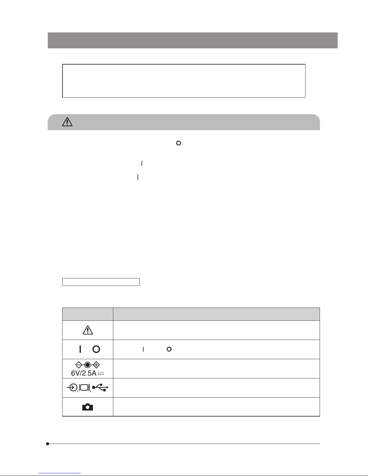
Safety and Operation Symbols
The following symbols are found on the control box of the system.
Study the meanings of the symbols and always use the equipment in the safest possible manner.
Symbol Explanation
Before use, carefully read the instruction manual. Improper use could result in personal injury
to the user and/or damage to the equipment.
Indicates “ ” (ON) or “ ” (OFF) of the main switch.
Use the specified AC adapter (6 V, 2.5 A DC)
Symbols representing an input connector, display, and USB connector respectively.
Symbol representing the camera head connector.
,
Page 6
2
Restrictions
1. The standard TV adapter is the U-TV1X-2 or the U-TV0.5XC-3.
The U-TV0.25xC or U-TV0.35xC (TV adapter with a magnification below 0.5X) and the U-TV0.5XC/GX-TV0.5XC-DP cannot
be used because of their optical performances.
2. When the DP20 is mounted on the rear port of the U-DPT or U-MPH, the image in the peripheral area will degrade due to
the optical performances of the port.
3. When using two intermediate attachments by stacking one on the other, the peripheral area may become dark or
obscured depending on the types of the observation tube and objective used.
4. Under fluorescent lamp illumination, the image may flicker.
5. When the DP20 is combined with a non-Olympus microscope or a commercially available C-mount lens, problems due
to optical adaptability such as shading may occur. Also when using a commercially available C-mount lens, make sure
that neither screw protrusion from the C-mount abutting section nor lens protrusion exceeds 4.5 mm.
6. When the aperture iris diaphragm is stopped down near the minimum aperture during observation of a low-contrast
specimen (nearly colorless and transparent) or high-reflectivity specimen (near mirror), spot flare may be noticeable.
7. When edge observation of a non-transparent subject is performed using the STM combination under transmitted light
illumination, flare may be noticeable due to the difference in brightness between the transmitted area (over-exposure) and
opaque area (under-exposure). In this case, the flare can be reduced by reducing the exposure by means of exposure
adjustment or by using manual exposure.
<< SMT6 combination details >>
Edge observation using the combination MM6C-VL + MM6-ETR and MM6-OB3X/5X/10X objective.
8. This system cannot photograph dark specimens in reflected light fluorescence or darkfield observation (a specimen that
required exposure of 1/2 sec. or more when the ISO is equivalent to 100).
9. If the specimen has a distribution unsuitable for center average metering, it is necessary to use spot metering or exposure
adjustment.
10. When image magnification with electronic zooming is used during focusing, the image may become noticeably rough
with certain specimens.
11. The frame rate for live image (15 fps) is possible when the exposure time is no more than 1/15 sec.
12. When the scale photographing function or measurement function is selected, the image capturing time may be longer
than usual.
13. The tracking of the auto white balance function is deteriorated when the specimen has little white region.
14. The measurement function (not including the scale display function) requires a display resolution of 1600 x 1200 with
UXGA or 800 x 600 with SVGA. The measurement of playback picture is possible only with a TIFF image that has been
photographed with the scale display ON. It is not possible with JPEG images.
The measurement results are superimposed on the image display, but not compiled into a file such as a text file.
15. The available Compact Flush (CF) file formats are FAT and FAT32. Other file formats such as NTFS are not compatible.
If the CF card you want to use is in a format other than FAT or FAT32, you need to format the CF card properly on the PC
before use.
16. The recommended recording medium is the Compact Flash (CF card Type I, up to 4 GB) by SanDisk or Lexar. (For the CF
card models we already confirmed operation, see page 11.)
Operating Environment
Temperature: 0° to 35°C (32° to 95°F). Humidity: 20% to 85% (without condensation).
Recommended display specifications
Full-color capable monitor, 800 x 600 or better. (The factory setting is 1600 x 1200.)
Compliance with the VESA DDC2B standard.
1
Conformity of the System
17. The DP20 picture downloading software/USB driver cannot be used in the camera control (including recording).
18. When connecting a PC to the DP20, connect the DP20 control box to the USB2.0 port of the PC directly. If a connection
through a USB hub is used, malfunction may occur.
Page 7
3
DP20
CAUTION The control box incorporates a lithium ion coin battery used for data backup. This lithium battery has
a service life of about 6 years.
Because the control box incorporates a lithium ion coin battery (CR1220), be sure to check local
regulations for proper disposal procedures when disposing of it.
1. The camera system uses precision components. Handle it with care and avoid subjecting it to a sudden or severe
impact.
2. Do not use the camera near a source of strong electromagnetic waves. Otherwise, the displayed picture will be disturbed
and malfunction or failure may also result.
3. When mounting the camera head on a tripod, attach it by using the DP-TRAD tripod adapter, which is separately available.
4. Do not use the camera system in areas where it may be subjected to direct sunlight, high temperature and humidity, dust
or vibrations. For the operating environment conditions, see Chapter 9, “SPECIFICATIONS” on page 46.
1. To clean the lenses and other glass components, simply blow dirty away using a commercially available blower and wipe
gently using a piece of cleaning paper (or clean gauze).
If a lens is stained with fingerprints or oil smudges, wipe it gauze slightly moistened with commercially available absolute
alcohol.
Since the absolute alcohol is highly flammable, it must be handled carefully. Be sure to keep it away from open
flames or potential sources of electrical sparks -- for example, electrical equipment that is being switched on or
off. Also remember to always use it only in a well-ventilated room.
2. Parts other than the glass components should be cleaned by wiping with a clean cloth. Do not use organic solvents to
remove major stains. Use a soft cloth slightly moistened with a neutral detergent solution.
3. To avoid any degradation in performance, do not attempt to disassembly or modify any part of the system.
4. When not using the camera system, keep it covered with the dust cover provided with the microscope.
If the camera system is used in a manner not specified by this manual, the safety of the user may be imperiled. In addition,
the camera may also be damaged. Always use the equipment as outlined in this instruction manual.
2
Getting Ready
3
Maintenance and Storage
4
Caution
Recorded picture data may be lose (or destroyed) in any of the following cases. Please note that
Olympus assumes no liability for loss of recorded data. The user is recommended to back up the
recorded data periodically.
· Improper handling of the Compact Flush (CF card) by the user or a third party.
· Unauthorized servicing by the user or a third party.
· If the CF card is removed, the main switch is set to “ ” (OFF), the AC adapter or power cord is
disconnected during recording or erasure (including initialization) of a CF card.
· General equipment failure.
The following symbols are used to set off text in this instruction manual.
: Indicates that failure to follow the instructions in the warning could result in bodily harm to the
user and/or damage to equipment (including objects in the vicinity of the equipment).
# : Indicates that failure to follow the instructions could result in damage to equipment.
} : Indicates commentary (for ease of operation and maintenance).
Data Storage Caution
Page 8
4
1
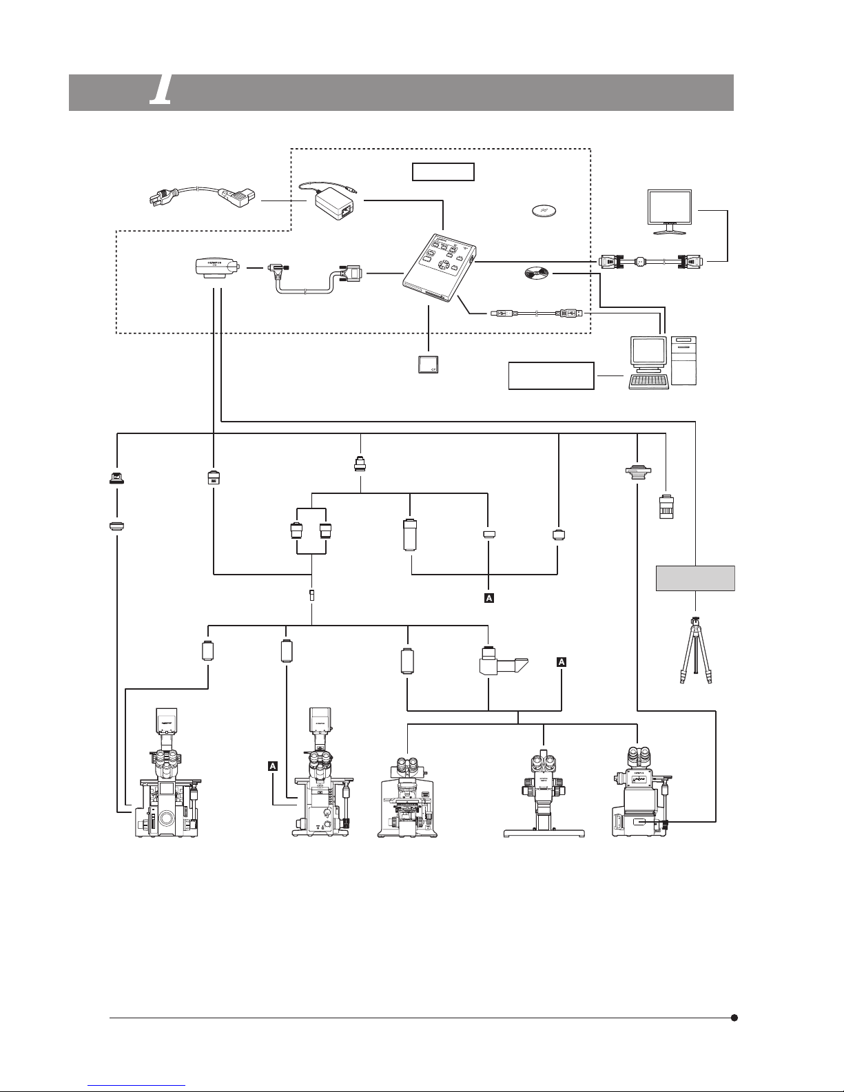
SYSTEM CHART
Power cord
DP20-SET
AC adapter
Control box
Camera head
Camera cable
Picture downloading
software/USB driver
Display
Display cable
Compact Flush (CF card)
((Type I only)
Commercially
available printer
PC
U-CMT
C/T Mount
IX-TVAD
TV Adapter
U-PMTVC
C-Mount
Attachment
U-PMTV
TV Attachment
U-PMTV1X
TV Attachment
,
1X
U-CMAD3
C-Mount Adapter
U-TV0.5X
TV Adapter,
0.5X
U-TV1X-2
TV Adapter,
1X
GX-TV0.5XC
C-Mount
TV Adapter,
0.5XC
GX-TV0.7XC
C-Mount
TV Adapter,
0.7XC
U-TV0.5XC-3
C-Mount
TV Adapter,
0.5X
C-mount
lens
DP-TRAD
Tripod Adapter
Commercially
available tripod
IX-SPT
Straight
Photo Tube
IX2-SPT
Straight
Photo Tube
for IX2
U-SPT
Straight
Photo
Tube
U-DPT
DoublePort Photo
Tube
IX70/IX50*
Inverted
Microscope
IX81/IX71/IX51
*
Inverted
Microscope
AX80/AX70
BX61/BX51/BX41
CX41*/CX31*
MX80/MX50/MX40
MX61L/MX61/MX51
Upright Microscope
SZX12/SZX8
SZX7/SZ61
Stereo
Microscope
GX71/GX51
Inverted
Metallurgical
Microscope
(Note) Certain microscopes are also applicable even when they are not mentioned above. Please contact Olympus.
*When using a microscope illuminated with a 30 W halogen bulb (CX/CKX/IX51/IX50), engage the 45HA2 filter in the
light path to ensure faithful color reproduction.
USB 2.0 cable
PE Photo
eyepiece
Color Adjustment
Filter 45HA2*
(For 30 W halogen bulb)
Page 9
5
DP20
A
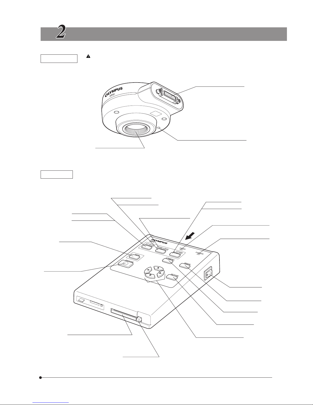
NOMENCLATURE
Camera Head
Any equipment connected to the camera head should be an Olympus-specified product or a
product in compliance with the requirements of IEC60950 or CISPR22/24. If equipment other
than these products is connected, Olympus cannot guarantee proper performance of the camera.
Control box connector (P. 9)
Threaded C-mount (P. 8)
Tripod adapter mount screw holes (P. 8)
Control Box
* Some buttons are shown with two functions per button. In this case, the function in the upper row indicates
that in REC mode and that in the lower row indicate that in PLAY mode.
*SPOT button (P. 14)
*PRINT button (P. 31)
INFO button (P. 13)
EXPOSE button (P. 16)
CF card slot (P. 11)
Compact Flush (CF card) Type I only.
Eject button (P. 11)
*AE LOCK button (P. 14)
*PROTECT button (P. 31)
AE LOCK indicator LED (P. 14)
OTWB button (P. 15)
ERASE button (P. 30)
Card access indicator LED (P. 11)
POWER indicator LED (P. 13)
MENU button (P. 17)
Main switch (P. 13)
MODE button (P. 13)
SET/OK button (P. 17)
Cross-cursor buttons (P. 17)
Page 10
6
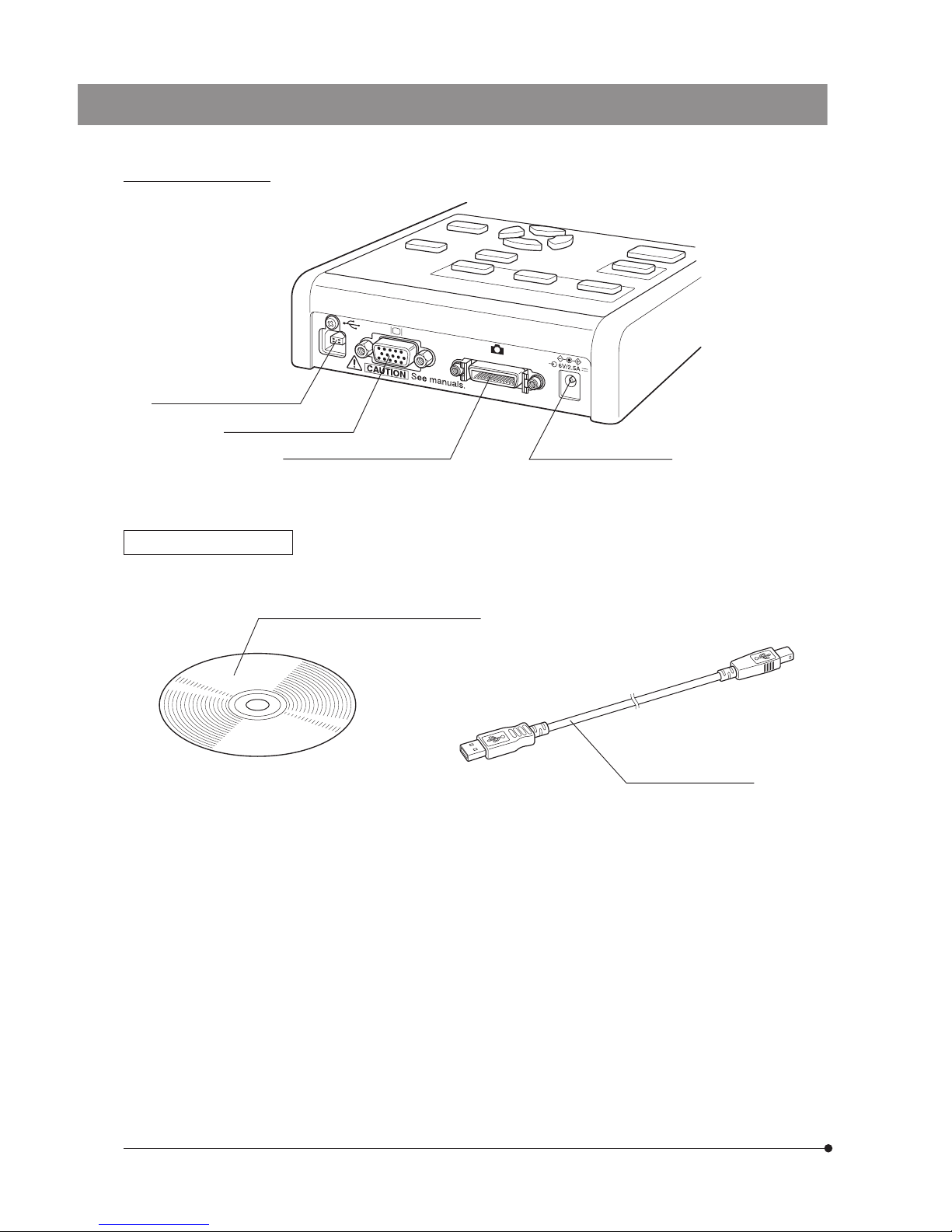
USB 2.0 connector (P. 36,38)
View from direction A
Display connector (P. 9)
Camera cable connector (P. 9)
DC input connector (P. 9)
DP20 Driver DP20-DRV
Picture downloading software/USB driver
USB 2.0 cable (P. 36,38)
Page 11
7
DP20
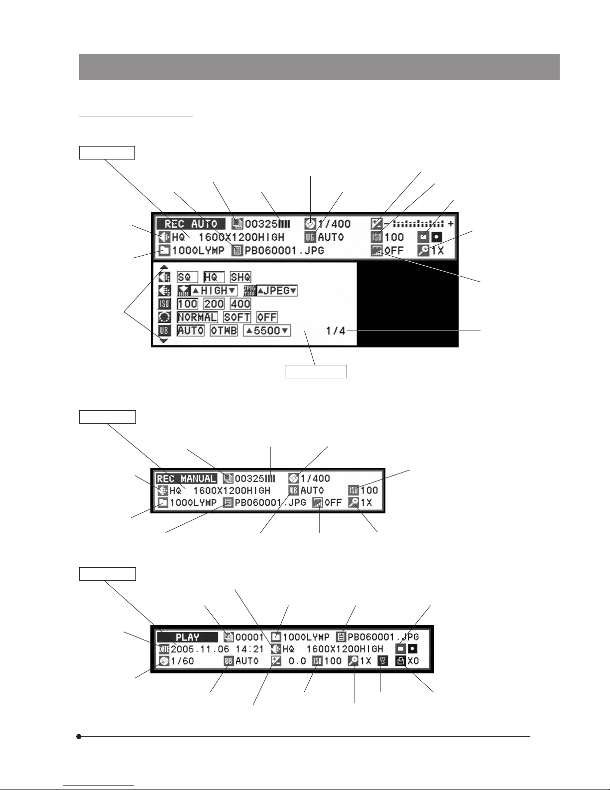
On-Screen Display Details
(Note) The auto exposure time is displayed only when the AE LOCK is set.
INFO display
(When REC AUTO is set)
Picture quality
(P. 18)
Folder name
(P. 20)
Page select
markings
File name (P. 20)
Number of remaining
pictures (P. 16)
Memory gauge (P. 16)
Auto exposure
time (P. 45)
White balance (P. 19)
Exposure adjustment (P. 18)
ISO speed (P. 18)
Metering area (P. 14)
Zooming (P. 15)
Scale (P. 21)
MENU display
}The setting items vary between REC AUTO, REC
MANUAL and PLAY. The display can be switched
using the page select markings. (See pages 17
to 28 for details.)
INFO display
(When REC MANUAL is set)
Picture quality
(P. 18)
Folder name
(P. 20)
Number of remaining
pictures (P. 16)
Memory gauge (P. 16)
Manual exposure time (P. 13)
ISO rating (P. 18)
File name (P. 20)
White balance (P. 19)
Scale (P. 21) Zooming (P. 15)
INFO display (When PLAY is set)
Date/time
(P. 25)
Picture frame No. (P. 16) Folder name (P. 20) File name (P. 20) Metering area (P. 14)
Exposure time
(P. 45)
White balance (P. 19)
Exposure adjustment (P. 13)
Picture quality (P. 18)
ISO speed (P. 18)
Zooming (P. 30)
Protect (P. 31) Print reservation (P. 31)
Page display
(P. 17)
Page 12

8
ASSEMBLY
This chapter pertains only to installation and assembly of the DP20 microscope digital camera system. For instructions on
how to assemble the microscope system and TV adapter being used with the camera system, refer to the appropriate
instruction manuals.
1
Attaching the Camera Head
(Figs.1 &2)
Screw the U-TV0.5XC-3 C-mount TV adapter @ into the threaded C-mount
on the bottom of the camera head ². If a different C-mount TV adapter is
used, follow its instruction manual.
· As the photographed field is as shown below, use a TV adapter
having magnification of 0.5X to 1X. (If a 0.35X TV adapter is used, the
periphery of the photographed image will become dark.)
Field number
22
0.5X (FN 17.6)
1X (FN 8.8)
· If a C-mount adapter from other manufacturer than Olympus is used, the
optical performance of the system may not be manifested fully.
Be careful in using a C-mount TV adapter or C-mount lens having
a longer thread length than 4.5 mm. Otherwise, the threaded
section will hit the cover glass inside the camera head and cause
damage to it.
When using a commercially available tripod adapter
b
a
}The DP-TRAD tripod adapter is provided with two types of screws (2
each) and an Allen wrench. Use only the Phillips screws (x 2) with the
DP20.
1. Attach the DP-TRAD tripod adapter ³ to the camera head | and clamp
them using the provided Phillips screws (x 2) with a Phillips screwdriver.
2. Attach the camera head to the threaded tripod hole screw of the tripod
adapter ³ and tighten the tripod’s clamping knob 5 to secure the
camera head.
Fig. 1
1
2
Fig. 2
3
4
5
Page 13
9
DP20
2
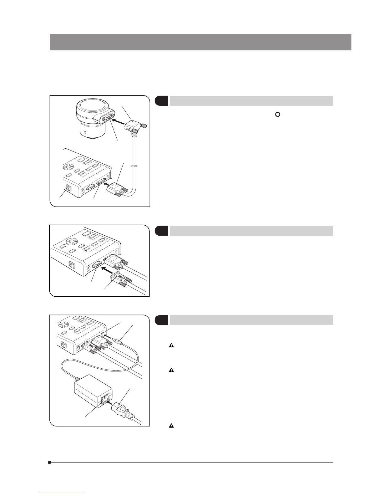
Attaching the Camera Cable
(Fig. 3)
#Be sure to set the main switch @ to “ ” (OFF) before cable
connection.
1. Insert the L-shaped connector ² of the camera cable into the connector
³ of the camera head, and tighten the locking screws on both sides of
the connector.
2. Insert the connector | on the other end of the camera cable into the
connector 5 of the control box, and tighten the locking screws on both
sides of the connector.
}If the L-shaped connector comes in the way of mounting the camera
head on the microscope, the L-shaped connector can be connected to
the control box.
Insert the connector @ of the cable from the display into the connector
² of the control box, and tighten the locking screws on both sides of
the connector.
#Always be sure to use the specified AC adapter. Using any other AC
adapter will result in a malfunction.
The cords and cables are vulnerable to bending or twisting. Do not
apply excessive force to them.
1. Insert the output connector @ of the AC adapter into the DC input
connector ² of the control box.
Always use the power cord provided by Olympus. If no power cord
is provided, please select the proper power cord by referring to
“PROPER SELECTION OF THE POWER SUPPLY CORD” at the end of
this instruction manual. If the proper power cord is not used, Olympus
can no longer warrant the electrical safety performance of the
product.
2. Insert the connector ³ of the power cord into the input connector | of
the AC adapter.
3. Insert the plug of the power cord into a power outlet.
Always ensure that the grounding terminal of the microscope and
that of the wall outlet are properly connected. If the equipment is not
grounded, Olympus can no longer warrant the electrical safety
performance of the equipment.
}The AC adapter gets hot when it has been connected to a power outlet
for a long period. This is not a malfunction.
Fig. 3
Fig. 4
1
2
Fig. 5
3 Attaching the Display Cable
(Fig. 4)
4
Attaching the AC Adapter
(Fig. 5)
1
2
3
4
5
1
2
3
4
Page 14

10
Always use a power supply with the specified voltage.
Do not operate the camera system when any of the connectors
and plugs of the AC adapter and power cord is not completely
inserted.
Never insert or remove the power cord’s plug or connector with
a wet hand.
If the AC adapter or cord is excessively hot or is emitting smoke
or odor, immediately stop using the camera system and remove
the power cord’s power plug from the power outlet.
Also immediately contact Olympus.
Never attempt to power the camera system using an AC adapter
other than the provided. Doing so could cause a failure in the
control box or camera head or result in an unexpected accident
such as a fire.
Out warranty cannot cover problems caused by the use of an
AC adapter other than the exclusive AC adapter provided with
the system.
Never pull, bend or twist the AC adapter cord or power cord
excessively or try to extend the power cord.
If the AC adapter cord or power cord is damaged or
disconnected or there is a contact failure in a connector or plug,
immediately contact Olympus.
Be sure to unplug the power cord from the power outlet whenever
the unit is not in use.
Do not use a multiple-outlet power sockets or several extension
power cords. Otherwise, an accident such as a fire may result.
To disconnect the AC adapter
Fig. 6
1
2
Set the main switch @ of the control box to “ ” (OFF), confirm that the
POWER indicator LED ² is turned off completely (in about 1 sec.), remove
the AC adapter’s output connector from the control box then remove
the power cord’s plug from the power outlet.
#Do not disconnect the connector while the indicator POWER LED
² is lit, as this may cause malfunction.
CAUTION
Page 15
11
DP20
5
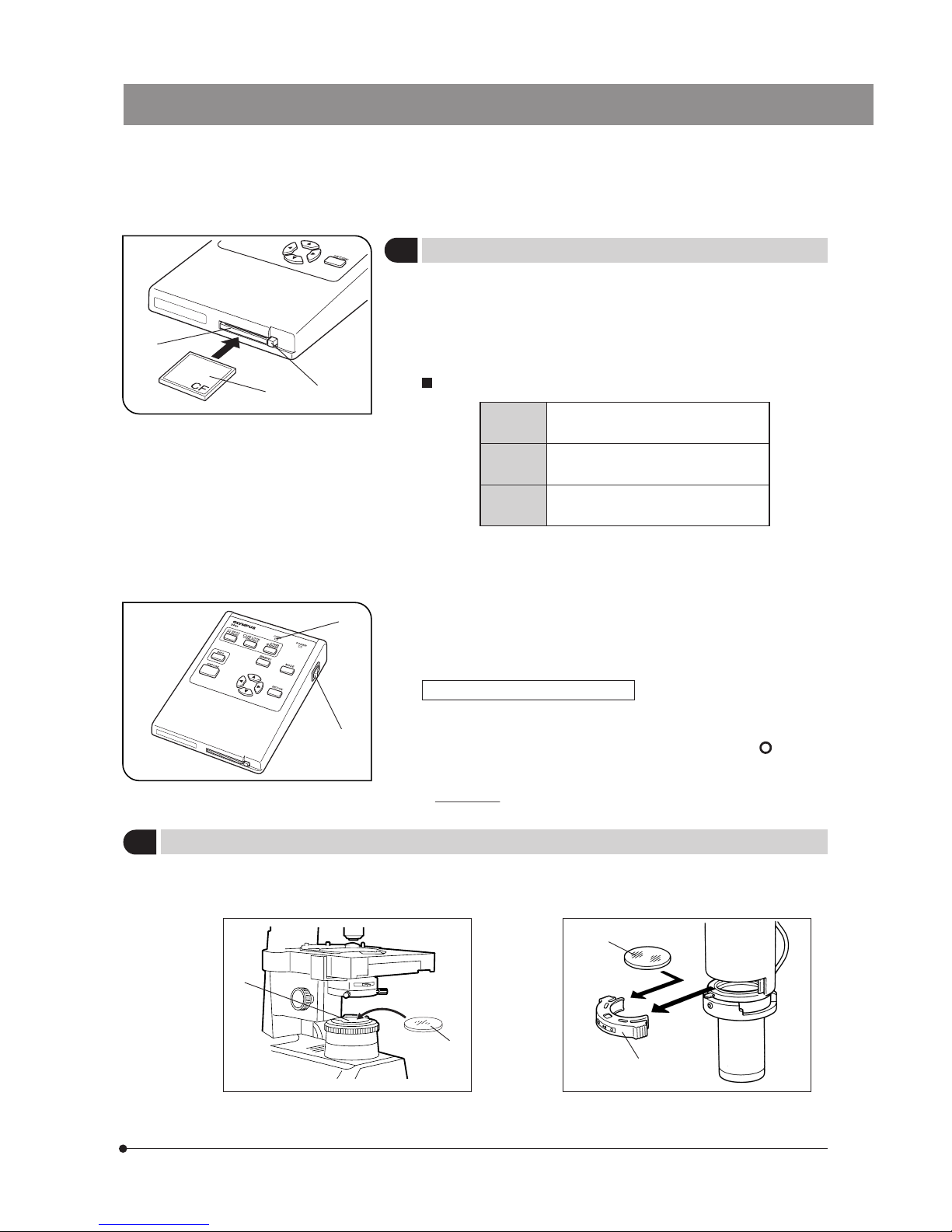
Inserting the Compact Flush (CF Card)
(Fig. 7)
#Only the Compact Flush (CF card) of Type I (thickness 3.3 mm) can
be used.
Do not attempt to insert a CF card Type II or Microdrive (thickness
5 mm).
}To ensure performance, it is recommended to use a CF card with a
capacity up to 4 GB manufactured by SanDisk or Lexar.
Applicable CF cards (with which Olympus has confirmed operation)
SanDisk SDCFB Series: Max. 4G bytes.
Ultra II Series: Max. 4G bytes.
Lexar Entry Series: Max. 256M bytes.
Professional Series: Max. 4G bytes.
Buffalo Standard type: Max. 512M bytes.
High 100x-speed type: 1G bytes.
1. With the label @ facing up, insert the connector end of a CF card into the
CF card slot ² of the control box as far as it will go.
2. To remove the CF card, push the eject button ³ so that a button pops
out.
3. Press the eject button ³ again. When the CF card comes out, pick it
with a finger and pull it out.
#Take care in handling the CF card immediately after ejection be-
cause it may be hot (up to about 50°C under normal use).
Fig. 7
1
2
3
Fig. 8
4
Card access indicator LED (Fig. 8)
The card access indicator LED | blinks or lights steadily when the
card is being accessed.
Do not remove the CF card, set the main switch 5 to “ ” (OFF) or
disconnect the AC adapter in this period.
#Otherwise, the picture data recorded in the CF card may be
destroyed.
5
6
Inserting the 45HA Color Adjustment Filter
}The 45HA color adjustment filter @ should be inserted in the filter holder ² only when the microscope in use employs the
30 W halogen-bulb light source (i.e. microscope model CX/CKX/IX51/IX50).
CX
CKX
IX51
IX50
1
2
1
2
Page 16
12
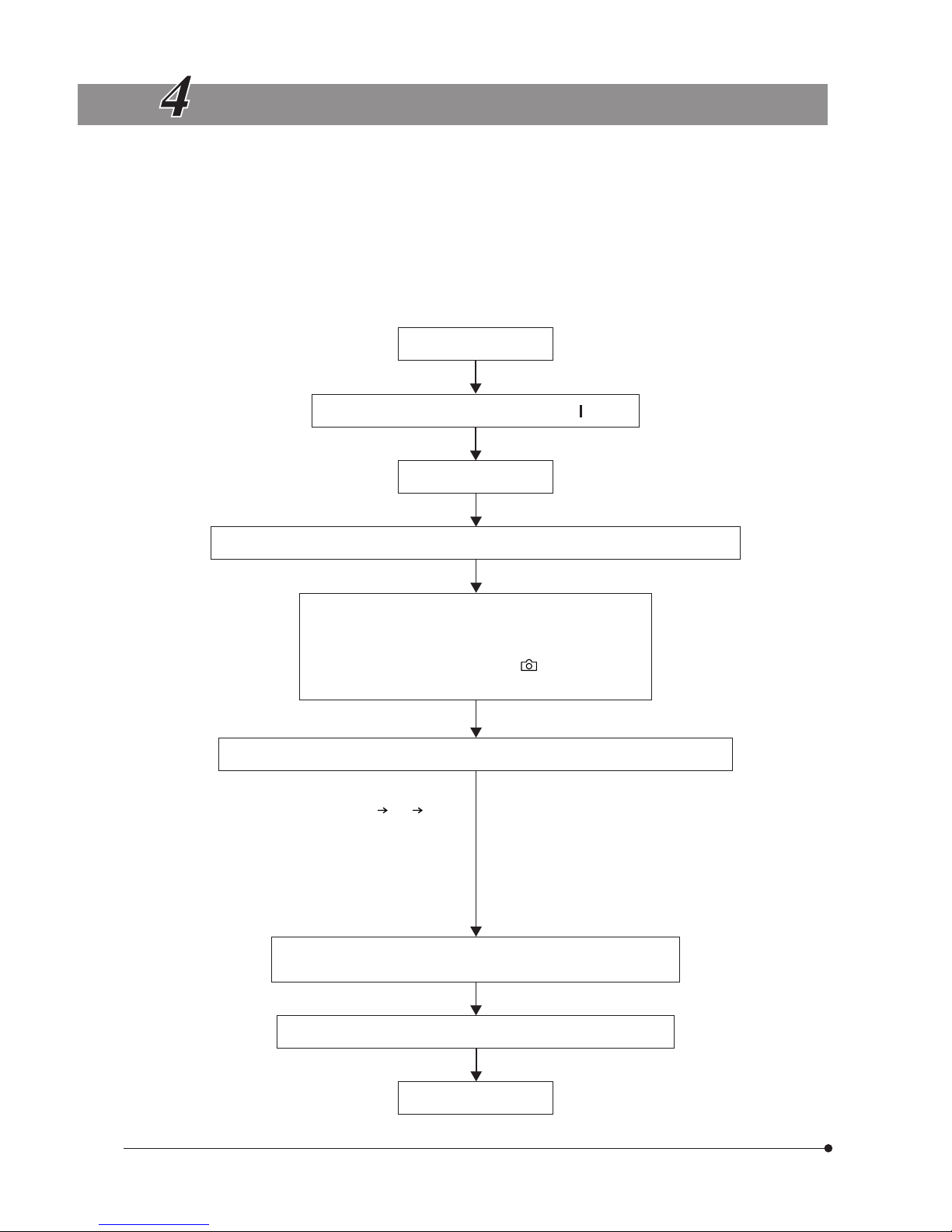
DIGITAL IMAGE PHOTOGRAPHING/RECORDING PROCEDURE
· Perform all necessary optical adjustments on the microscope.
(The camera system can photograph and record microscope observation images under transmitted and reflected
light illumination as well as other observation techniques (except fluorescence microscopy).
· Use the TV adapter to perform the confocal adjustment between the microscope’s eyepieces and the display
image. (Refer to the instruction manual for your TV adapter for details.)
· The factory setting for the white balance control is AUTO, but this may sometimes be inappropriate for microscopic
specimens with small white parts. When photographing a microscopic specimen, it is recommended to use the
one-touch white balance (OTWB) facility.
Insert a CF card.
(P. 11)
Set the main switch of the control box to “ ” (ON).
(P. 13)
Select REC mode REC MANU or REC AUTO (P. 13)
Set the light path selector knob of the microscope to the photographing (TV) light path.
Adjust the brightness of the microscope.
· Engage the LBD filter in the microscope’s light path.
· Set the intensity control to the indicator or the
specified voltage.
Check the focusing and brightness of the specimen (by viewing the display screen).
<< Focusing procedure >>
· The live image can be zoomed from 1X 2X 4X to
facilitate focusing. Focusing is easier at high zoom
magnifications. (P. 15)
· The optimum focusing position can be identified easily
by displaying the focusing indicator on the display.
(P. 23)
· If the brightness is too high, reduce it by using ND filters.
(Note) Brightness control based on the light intensity
voltage adjustment may be affected by variation in
the illumination color temperature.
· Adjust the picture quality, SPOT, AE LOCK and exposure
adjustment as required.
· The brightness and colors of the live images displayed
on the display may differ from actually recorded pictures.
Check the framing (recording area). (If a live image has been
displayed in a magnification other than 1X, return it to 1X.)
(P. 15)
Press the EXPOSE button to photograph and record a picture.
· Check the recording result. (P. 29)
(P. 16)
Enter PLAY mode.
(Note) Set the light intensity
knob to the maximum
position when using a
CX microscope.
Page 17
13
DP20
RECORDING FUNCTION SETUPS/OPERATIONS (REC)
5-1 Operations Using the Control Box Buttons (REC)
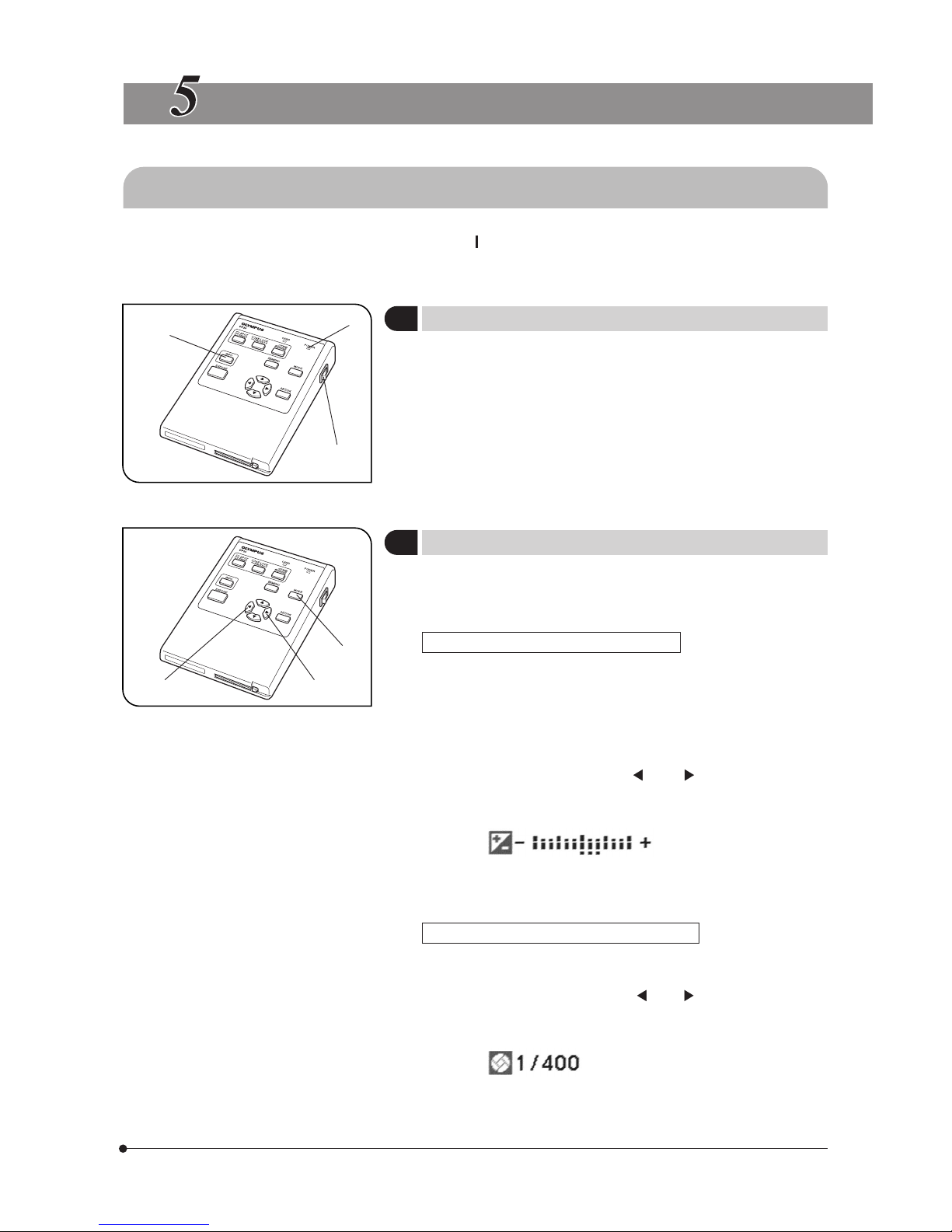
}After installing the CF card, set the main switch @ to “ ” (ON) and confirm that the POWER indicator LED ² lights up.
(The display shows an image in about 5 seconds after the indicator ² lights up.)
}For the display resolution setting, see page 26.
1. Press the INFO (recording information) button ³ to display or hide the
INFO display alternately.
To perform setups, it is required to display the INFO display. (Factory
setup: INFO display ON.)
2. The displayed information contents are variable depending on the
REC AUTO (auto recording), REC MANUAL (manual recording) and
PLAY (playback) mode setting. (For the INFO display in each mode,
see page 7.)
}Press the MODE button @ to switch the mode between REC AUTO
(auto recording), REC MANUAL (manual recording) and PLAY (playback).
1. Select a record mode, which is either REC AUTO or REC MANUAL.
Exposure adjustment in REC AUTO mode
}The exposure in REC AUTO mode can be corrected in the range of ±2
EV in 1/2 EV steps.
When the specimen is darkish, positive correction is effective because
this provides an overexposure effect by extending the exposure time.
When the specimen is too bright, negative correction is effective because
this provides an underexposure effect by reducing the exposure time.
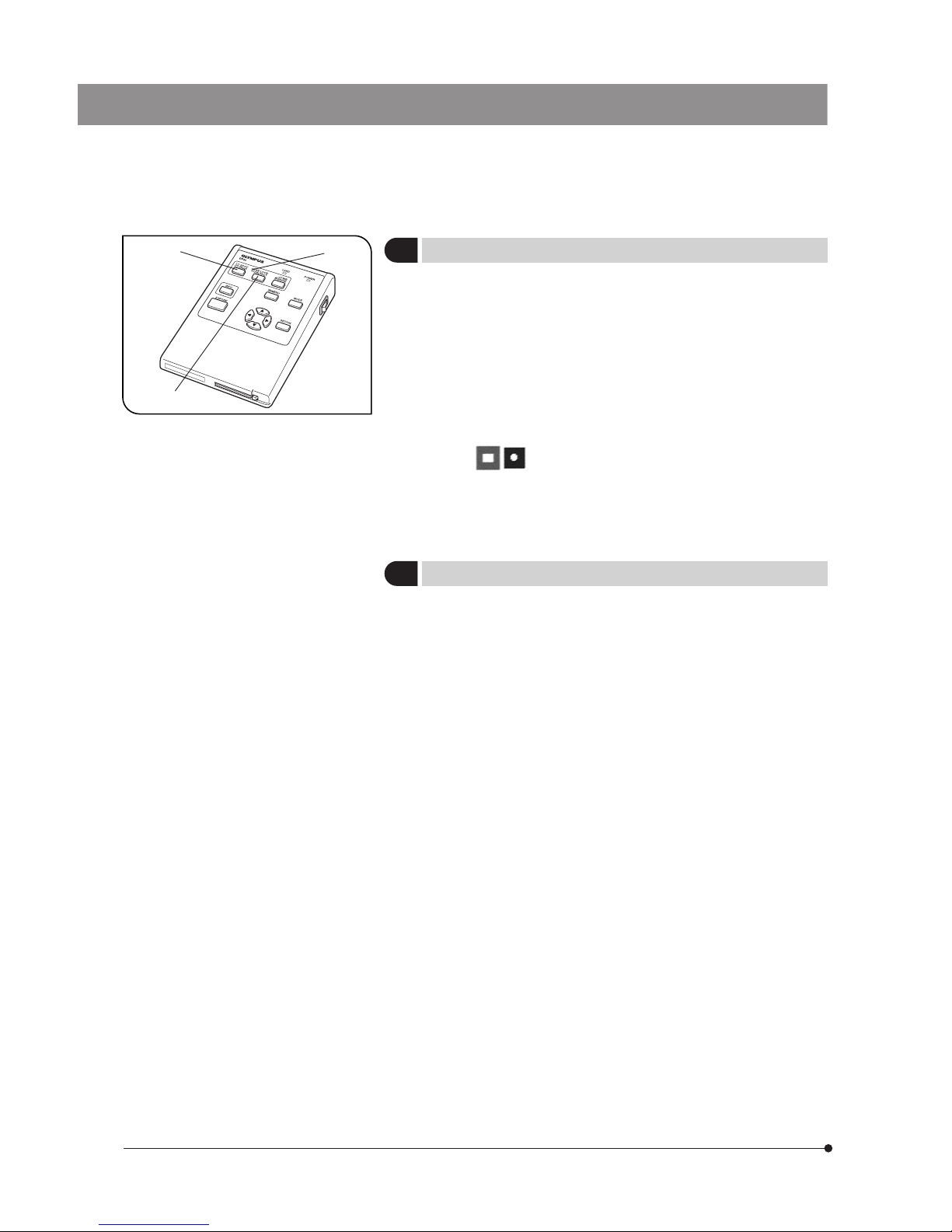
· Press either cross-cursor button ² or ³ to set the exposure
adjustment value. The setting can be confirmed on the following scale
on the INFO display.
(Example) +2/3 EV
}Provided that the beep tone is set to ON, warning composed of three
short beeps is generated when the upper or lower limit is reached.
1
Setting the INFO Button
(Fig. 9)
2
Setting the MODE Button
(Fig. 10)
Fig. 9
1
2
3
Fig. 10
1
2
3
Exposure adjustment in REC MANUAL mode
}The exposure time should be set manually in REC MANUAL mode.
The setting range is between 8 and 1/20000 sec.
· Press either cross-cursor button ² or ³ to set the exposure
time. The setting can be confirmed on the following scale on the
INFO display.
(Example) 1/400 sec.
-2EV 0 +2EV
Page 18
14
3
Setting the SPOT Metering
(Fig. 11)
}The camera system measures light using the center-weighted average
method when the spot metering method is not used.
· Center-weighted average metering: Photometry method measuring
light in the central 30% area of the
field.
· Spot metering: Photometry method measuring only the light at the
central 2.5% area of the field.
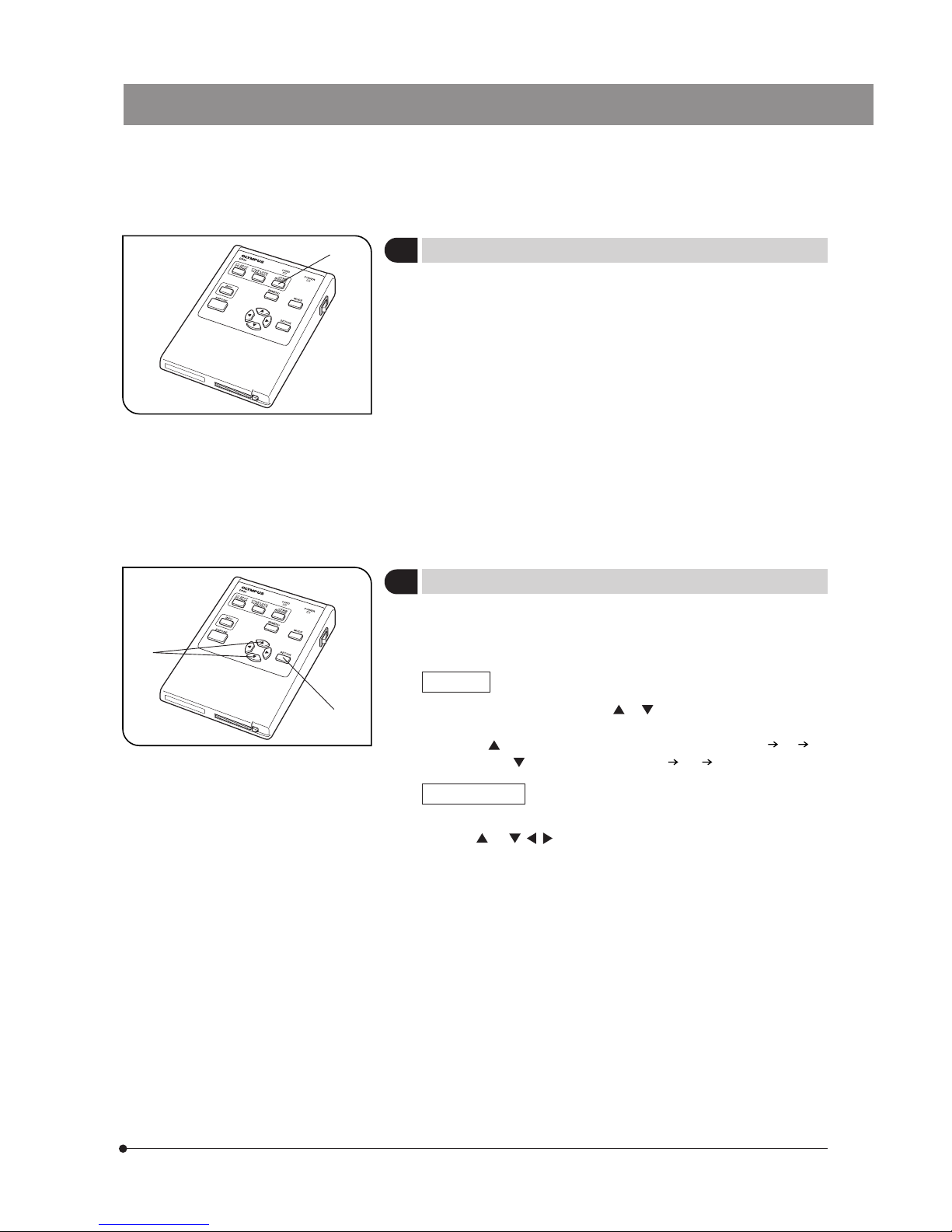
1. Press the SPOT button @ to switch the spot and average metering
methods alternately. The setting can be confirmed on the INFO display.
(Example) Spot metering is set.
2. The metering area can be displayed according to the setting in the menu.
When the metering area is set to be hidden, it is displayed only for 3
seconds after the SPOT button is pressed but then is hidden again.
}By moving the slide position with the average specimen distribution at
the center and locking the exposure time, the following effects can be
achieved.
· Even when a specimen is recorded by varying the compositional
arrangement many times, the specimen area can always be recorded
with an optimum exposure.
· When a linked picture like panoramic photo is created, the joints
between pictures are not noticeable when their exposure is constant.
1. Move the specimen slide to bring the area where you want to lock the
exposure time at the center.
2. Press the AE LOCK button ² .The current exposure time is locked and
the AE LOCK indicator LED ³ lights up.
If the current metering mode is set to SPOT mode, it cannot be canceled
until AE LOCK is canceled.
Press the AE LOCK button again to cancel AE LOCK.
When AE LOCK is canceled, the exposure time display in the INFO
display becomes “-------”.
Fig. 11
1
2
3
4
Setting AE LOCK (REC AUTO only)
(Fig. 11)
Page 19
15
DP20
5
Setting OTWB
(Fig. 12)
}Even when the OTWB (One-Touch White Balance) function is not used,
the auto white balance control and the color temperature setting are also
available using the menu (see page 19).
1. Set the specimen image white.
· In transmitted light observation: Remove the specimen.
· In reflected light observation: Use a sheet of white paper as the
specimen.
2. Press the OTWB button @ to set the white balance.
3. “OK” appears on the display screen when the white balance is set
and disappears automatically in 3 seconds.
Other button operations are accepted even when “OK” is being displayed.
When auto white balance setting fails, “NG” is displayed. As it continues
to be displayed, press any button so that it disappears before retrying
OTWB.
}When OTWB begun in other mode than OTWB mode fails, the previous
status remains unchanged.
}When the display in use complies with the VESA DDC2B standard, the
live image resolution is set to the optimum resolution for the display.
If the live image is not displayed, set it using the menu (see page 26).
Zooming
Press either cross-cursor button or @ to magnify the live image by
means of electronic zooming.
Pressing varies the zoom magnification in order from 1X 2X 4X,
and pressing varies it in order from 4X 2X 1X.
Zoom scrolling
While holding the SET/OK button ², Press either cross-cursor
button or , , to scroll the zoomed image.
The entire image area can be scrolled even during 2X or 4X display.
Fig. 12
1
6
Checking the Live Image
(Fig. 13)
Fig. 13
1
²
Page 20
16
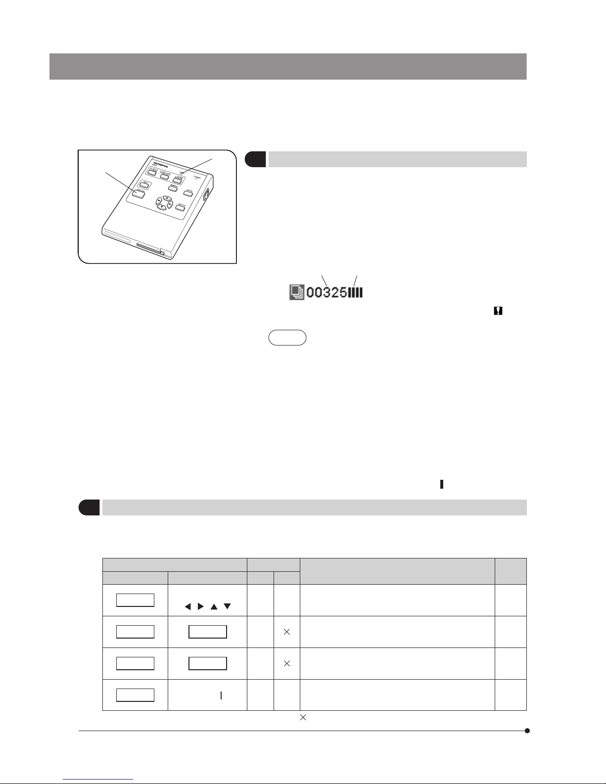
1. Press the EXPOSE button @ to photograph and record a single picture.
The card access indicator LED ² blinks while the photographed picture
is recorded in the CF card.
2. Successive photographing of several pictures is possible because the
EXPOSE button is accepted for the same number of times as the number
of bars ³ in the memory gauge even during recording.
The next picture to be recorded can be confirmed by setting QUICK
REV to “OFF”.
3. The number of remaining pictures | is shown in the INFO display.
(Example) Number of remaining pictures: 325
Number of memory gauge bars: 4
#When the number of remaining pictures becomes 0, the “ CARD
FULL” error message is displayed.
NOTES
· As the data amount is variable depending on the recording
object, the actual number that can be recorded may
sometimes exceed the displayed number of remaining
pictures. Also, there may be cases in which the number of
remaining pictures does not decrease even after recording
a picture or does not increase even after erasing a picture.
· The number of remaining pictures is also variable
depending on the capacity of each CF card.
· The number of remaining pictures is also variable when
the CF card contains a DPOF print reservation file, etc.
· The CF card has a service life. The available capacity may
decrease depending on the status of the flash memory
incorporated in the CF card.
· The maximum limit of available pictures is 10,000 even
when the CF card has an available capacity remaining in it.
· The memory gauge bar shows “ ” during recording.
Fig. 14
1
2
7
Using the EXPOSE Button
(Fig. 14)
}Pressing two buttons makes it possible to perform various settings quickly.
To perform a composite-button operation, hold down the “held button” and then press the “switching button” while the
menu is not displayed.
Composite buttons
8
Composite Button Operations
Mode
Setting Details
Ref.
Page
Held button Switching button REC PLAY
SET/OK
Cross-cursor button
Starts scrolling on an image displayed with a zoom
magnification of 2X or 4X.
15, 30
SET/OK MENU
Changes the registered data number setting in the
scale setting.
(Each press of the MENU button decreases the number.)
21
SET/OK MODE
Same as above.
(Each press of the MENU button increases the number.)
21
MENU Main switch “ ” (ON)
Turns the system ON with the display resolution of
VGA 600 x 480.
26
¦ : Available. : Not available.
¦
¦
¦
¦
¦
¦
³|
Page 21
17
DP20
Fig. 15
1
2
3
4
5-2 Operations Using the Menu (REC)
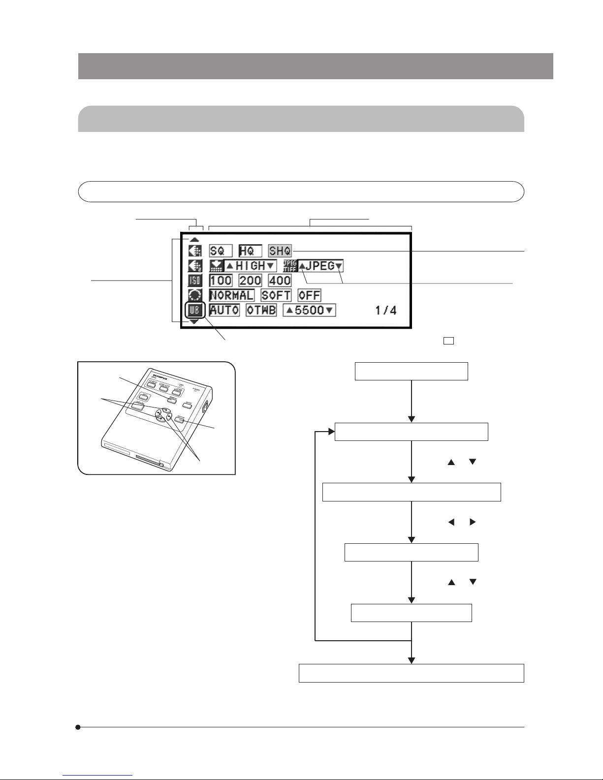
}By displaying the menu on the display, the functions of the system can be set up or run through the menu.
The displayed menu items are variable in the REC AUTO/REC MANUAL and PLAY modes.
5-2-1 Basic Flow of Menu Setup
Page select markings
Setting item icons Setting option list
Current setting position (Blue)
Indicates the option being
selected.
Sub-item setting markings
Press the MENU button @.
The menu appears on the
display.
Move the cursor on a setting item icon.
To set other setting item
Press either cross-cursor
button or ³ to select
the desired option.
Move the cursor on the option to be selected.
Press either cross-cursor
button or ² to select
the setting item icon.
When the option has sub-items:
Press either cross-cursor
button or ² to select
the desired sub-item option.
Press the SET/OK button |.
The selected option is set
and the cursor returns to the
setting item.
Press the SET/OK button | again to exit from the menu.
The setting is established
and the menu disappears
from the display.
Current setting position (The set item is enclosed by green frame .)
(4 pages)
Page 22
18
Picture Quality Compression File Format Recording Pixels
Recordable Pictures
File Capacity
SHQ Fixed at Low
TIFF
1600 x 1200
44 5760 kB
JPEG 118 2140 kB
HQ Fixed at High Fixed at JPEG 1600 x 1200 345 720 kB
SQ
Low
Fixed at JPEG 1280 x 960
184 1365 kB
High 531 460 kB
5-2-2 Function Setup in Record Modes
· Press the MODE button to select REC AUTO or REC MANUAL.
· Press the MENU button to display the Menu.
· After setting, be sure to press the SET/OK button to establish the setting.
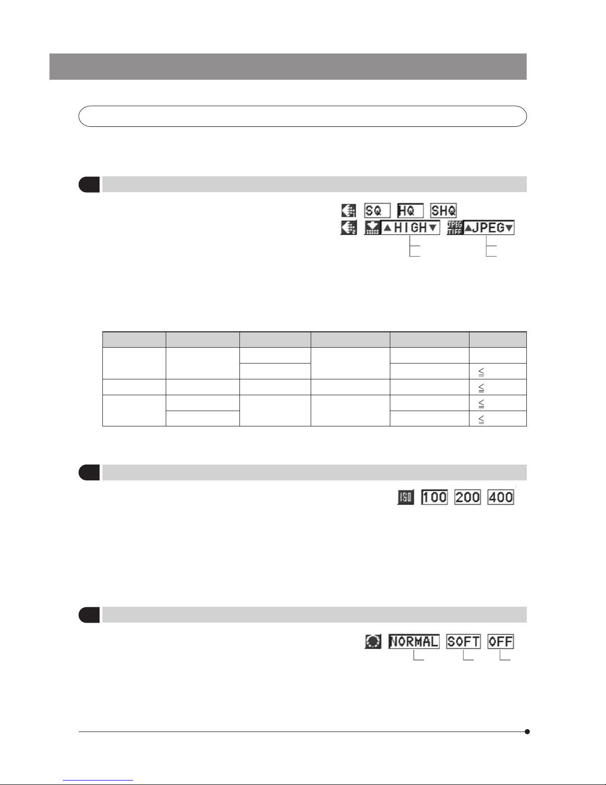
}Select the picture quality of the picture to be recorded.
The picture quality improves as the setting changes from “SQ”
to “HQ” and “SHQ”.
The factory setting for “SHQ” is SHQ/Low TIFF and that for
“SQ” is Low JPEG.
· Number of remaining pictures (per 256 MB CF card)
The number of recordable pictures is variable depending on
the set picture quality and the remaining capacity in the CF
card in use.
It may also vary depending on whether print reservation is
made and the specimen being observed.
1
Selecting the Picture Quality Mode
Factory setup: HQ/HIGH/JPEG
HIGH
LOW
TIFF
JPEG
}The compression rates are as follows:
SHQ (TIFF): No compression. SHQ (JPEG): 1/2.7. HQ (JPEG): 1/8. SQ (JPEG - Low): 1/2.7. SQ (JPEG - High): 1/8.
}The sensitivity (ISO rating) in recording can be set like a photo
film. The provided ISO values are set by converting the obtained
sensitivity into an ISO value of photography films.
Three ISO values including 100,200 and 400 are available. A
larger value indicates that the camera becomes more suitable
for recording darkish specimens or quickly moving objects.
#Although increasing the ISO value makes the camera
suitable for recording darkish specimens under low light,
it also results in increasing noise in the picture. Select the
appropriate ISO value according to situations.
3 Setting the Sharpness
Factory setup: NORMAL
}The sharpness of picture can be selected from three
options including “NORMAL” , “SOFT ” and “OFF”.
“NORMAL” provides sharp contours which is suitable for
printing and viewing, while “SOFT” reproduces more
natural contours. “OFF” does not correct the sharpness so
it is suitable for post-processing of images on a PC. Select
the appropriate sharpness according to situations.
2
Setting the ISO Speed
Factory setup: 100
Normal Soft Off
Page 23
19
DP20
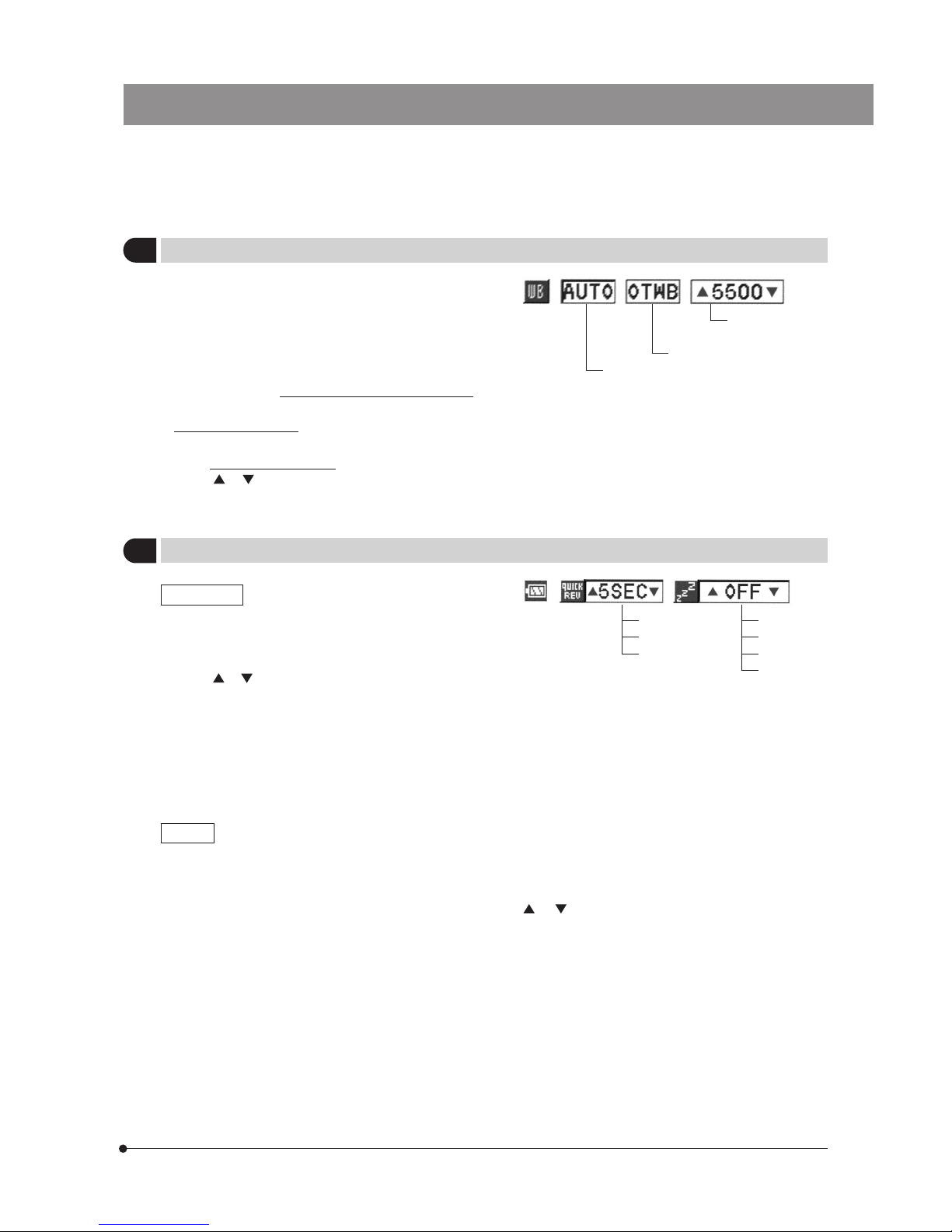
}This item selects whether or not a picture is displayed for
review during the period in which it is recorded I the CF card.
· After selecting item QUICK REV, press either cross-cursor
button or to select “AUTO”, “5 sec.” or “OFF”.
· When “AUTO” is selected, the display shows the picture during
recording.
· When “5 sec.” is selected, the display shows the picture only
for 5 seconds.
· When “OFF” is selected, the picture being recorded is not
displayed so this setting is suitable for use during successive
photographing of multiple pictures.
Auto white balance
One-touch white balance
Color temperature
setting
}The one-touch white balance setting is also available using
the OTWB button on the control box (see page 15).
}The white balance (WB) setting makes it possible to record
pictures by eliminating the effects of the surrounding light.
According to specimen and brightness, the optimum white
balance may not be obtained with AUTO white balance setting.
In such case, use OTWB (One-Touch White Balance) to let
the camera store the illumination condition in memory.
Manual white balance is also available, allowing you to set
the color temperature manually.
QUICK REV
SLEEP
}When this item is set to other option than “OFF”, the display turns off after the selected time period has elapsed
when you perform on operation on the camera system.
· After selecting item SLEEP, press either cross-cursor button or to select “OFF”, “1 min.”, “5 min.” or “10 min.”.
· When “OFF” is selected, the SLEEP function is deactivated.
When the measurement results are saved, the live image updating is interrupted for about 3 seconds even when
SLEEP is set to “OFF”.
4
Setting the White Balance
Factory setup: AUTO.
When manual white balance is selected, the current color temperature should be set by pressing either cross-cursor
button or .
(Factory setup: 5500K)
(The color temperature can be set to 3000K, 3700K, 4000K, 4500K, 5500K or 6500K.)
5
Setting the Power Supply
Factory setup: QUICK REV:5 sec./SLEEP:OFF
AUTO
5 sec.
OFF
OFF
10 min.
5 min.
1 min.
Page 24
20
6
Setting the File and Folder Names
Factory setup: RESET
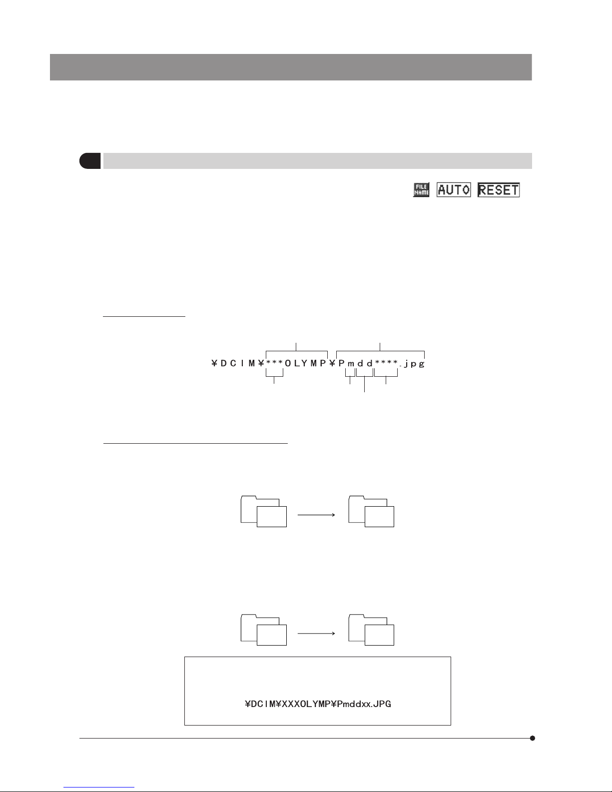
}The file storing a recorded picture and the folder storing the
file are named automatically inside the DP20.
The files are named in the range from file Nos. 0001 to 9999
and the folders are named in the range from folder Nos. 100
to 999.
The file and folder can be named by one of the two methods
including AUTO and RESET. These options can be selected
from item FILE MENU in the menu.
Note that the maximum number of image files that can be
stored on one CF card is 10,000. With TIFF images, the
maximum storable number is 5,000.
Folder name File name
Folder No.: 100 - 999 Month (1 - C)
Day (01 - 31)
File No. 0001 - 9999
* In the “Month” expression for the file name, January to September are expressed as “1” to “9”, October as “A”, November
as “B” and December as “C”.
How the folder and file are named in each mode
{AUTO
When the CF card is exchanged, the file No. becomes the number continuing the file Nos. which have been recorded on
the previously used CF card to avoid overlapping.
(Example) When a CF card recorded till Folder No. 100/File No. 0005 is exchanged with another CF card:
When pictures are copied file by file onto a PC, the file Nos. do not overlap even when the pictures were recorded in
multiple cards. Note that, however, when 9999 pictures have been recorded, the file No. returns to 0001.
{RESET
When the CF card is exchanged, both the folder No. and file No. are reset.
(Example) When a CF card recorded till Folder No. 102/File No. 0005 is exchanged with another CF card recorded till
Folder No. 105/File No. 0008:
· When a picture is copied onto a PC, the copied picture has the same
folder name as the copy source folder name, thereby making the data
management easier.
Same folder name as the copy source folder.
Folder and file names
A picture recorded with the DP20 is automatically given a folder name and file name as shown below.
Folder No. 100
File No.
0005
CF card
exchange
Folder No. 100
File No.
from 0006
Folder No. 102
File No.
0005
CF card
exchange
Folder No. 105
File No.
from 0009
Page 25
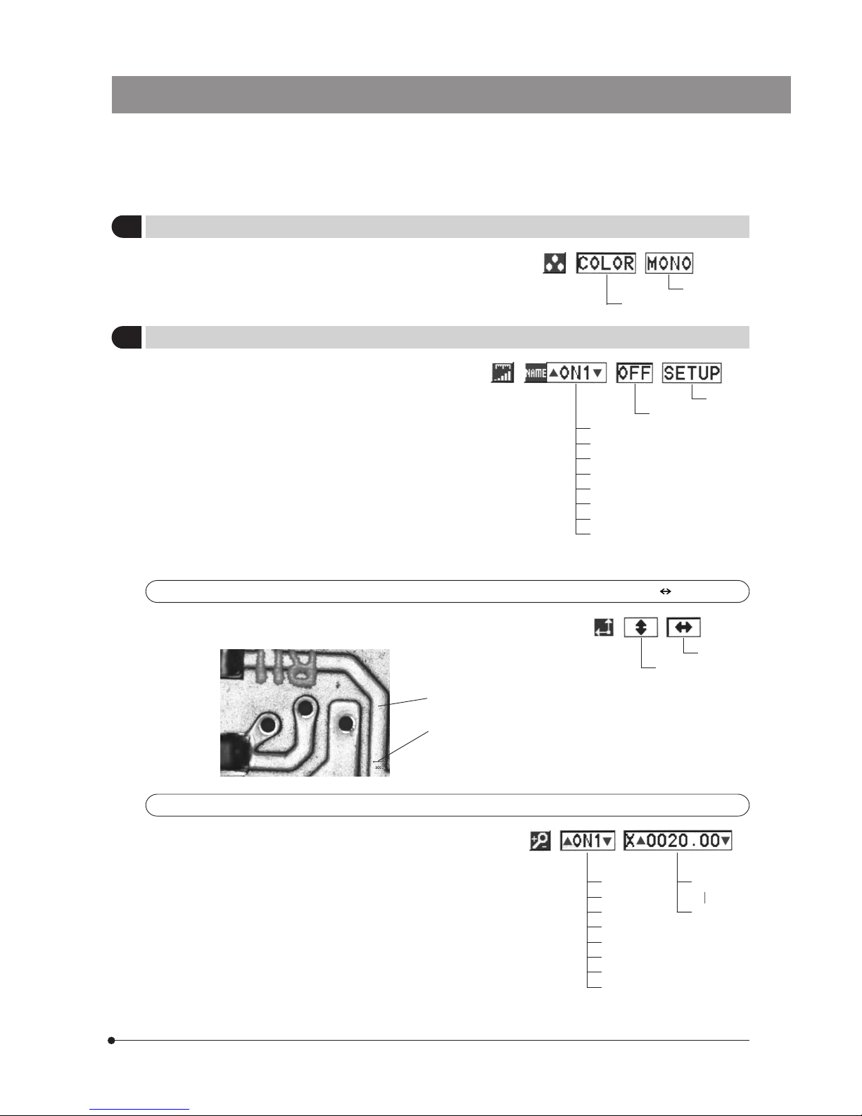
21
DP20
Scale display orientation setting
Factory setup: (Horizontal)
}This item sets whether a color picture or monochrome picture
is displayed.
The monochrome option is applied to the recorded pictures
as well as to the live images.
7
Setting the Color Picture Display
Factory setup: COLOR
Color
Monochrome
8
Setting the Scale Display
Factory setup: OFF
}The scale of the specimen image according to the
photographing magnification can be displayed only in the
live image or also in the recorded pictures. This setting is also
used in the measurements.
· Necessary scales can be stored under scale names from
“ON1” to “ON7”.
· The memory of “ON1” to “ON7” can store the scale display
position, photographing magnification, registered data
number, etc.
When SETUP is selected and the SET/OK button is pressed,
the menu showing the following items will be displayed.
}When the menu is set to be hidden, any of “ON1” to “ON7”
and “OFF” can be selected by pressing the SET/OK + MENU
buttons or SET/OK + MODE buttons.
ON1
ON2
ON3
ON4
ON5
ON6
ON7
TMP (Temporary Saving)
Detailed
setup
}This item sets the orientation of the scale display.
(Select either the horizontal scale display or vertical scale display.)
Display screen
Horizontal (or vertical) scale display
Vertical scale
Horizontal
Photographing magnification input/setting
Factory setup: ON1/0000.01
}This item is used to input the photographing magnification data,
which is required when displaying the scale. A magnification
value between 0000.01 and 9999.99 can be input.
< Photographing magnification calculation example >
· Objective (10X) x TV adapter magnification (0.5X) = 5X.
When the U-CA intermediate attachment with 1.25X is added
to the above, the total magnification will be 6.25X.
· For the magnification of a TV adapter, refer to the respective
instruction manual.
ON1
ON2
ON3
ON4
ON5
ON6
ON7
TMP (Temporary Saving)
}If it is required to input the accurate magnification value, use
an accurate scale (such as an objective micrometer disk with
scales dividing 1 mm into 100) and input the magnification
so that the displayed scale coincides with the accurate scale.
OFF
0000.01
9999.99
Page 26
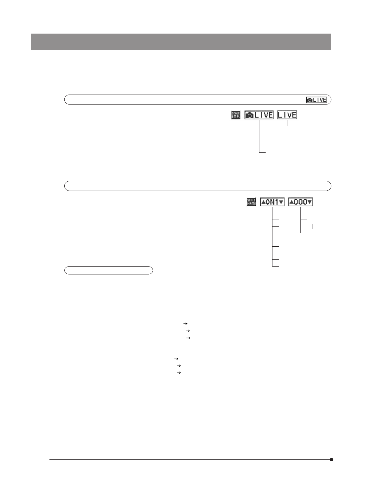
22
Scale display range
Factory setup:
}When the scale display is set, this item selects whether the
scale and measurements are displayed on the display screen
only or both in the display screen and recorded picture.
}The setting of this item is also applied to the measurement
function.
Display scale and
measurements in
both display and
recorded picture.
Display scale and
measurements
only on the display
screen.
Registered data number setting
Factory setup: ON1/000
}This item is used to set desired 3-digit numbers to the data in
ON1 to ON7.
This setting is not possible when the TMP (Temporary Saving)
setup is engaged.
Actual examples of scale settings
· Assume that the 4X,. 10X and 20X objectives are switched and a 0.5X TV adapter is used. Note that the magnification
of eyepieces does not affect the scale setting.
@How to calculate the available photographing magnifications
This is equal to Objective magnification x TV adapter magnification.
Therefore, it is 2X with the 4X objective, 5X with the 10X objective or 10X with the 20X objective.
²How to set the photographing magnifications
ON1: Set the magnification with the 4X objective. 0002.00 (which represents 2X)
ON2: Set the magnification with the 10X objective. 0005.00
ON3: Set the magnification with the 20X objective. 0010.00
³How to set the registered data number
}Any numbers can be set, but most convenient is to register the objective magnifications.
ON1: Since the objective magnification is 4X 004 (which represents the 4X objective)
ON2: Since the objective magnification is 10X 010
ON3: Since the objective magnification is 20X 020
|When performing microscopic observation using the 4X objective, set the registered data number to ON1/004. It
should be set to ON2/010 when the 10X objective is selected.
000
999
ON1
ON2
ON3
ON4
ON5
ON6
ON7
TMP (Temporary Saving)
Page 27
23
DP20
9
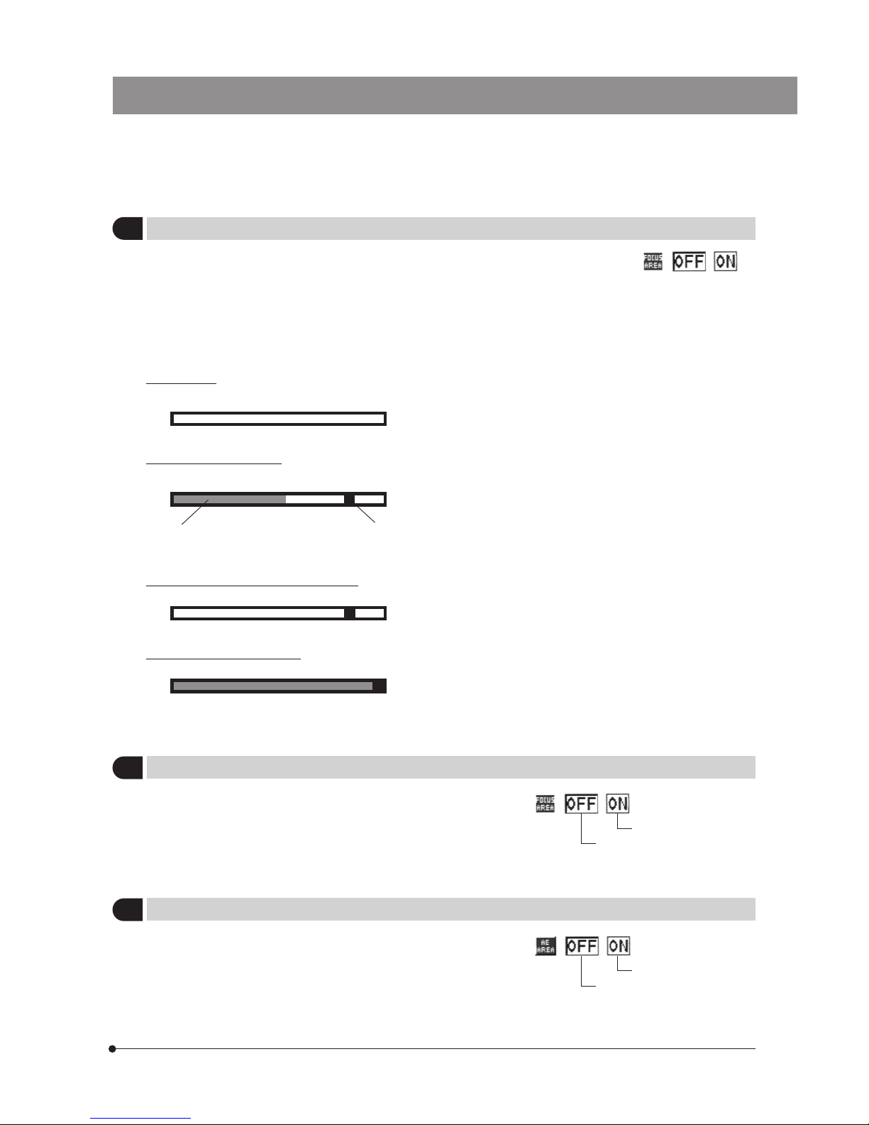
Setting the Focusing Indicator
Factory setup: OFF
}This item is used to display the focusing condition of the
incident light as a reference in focusing.
The focusing indicator is displayed as a bar at the bottom right of the display screen. It switches automatically to the
maximum meter level display according to the specimen contrast.
Initial display
This is the status immediately after this item is set to ON. Neither the current level nor the maximum level are indicated.
Current level Maximum level
Perform precise focusing so that the current level approaches the maximum level.
Level 0 = Evaluation impossible display
Maximum evaluation display
}The current level is updated every 0.1 second.
}The maximum level is updated when a higher level than the current maximum level is produced.
10
Focusing Area Display
Factory setup: OFF
}This item selects whether or not the focusing area is displayed.
The level calculation of the focusing indicator is performed
inside the focusing area.
Not displayed.
Focusing area displayed.
Normal condition display
The current level is indicated by the gray bar while the maximum level is indicated in red.
}This item selects whether or not the auto exposure area
(average metering or spot metering area) is displayed.
For the metering area setting, see page 14.
Not displayed.
AE area displayed.
11
AE Area Display
Factory setup: OFF
Page 28
24
12
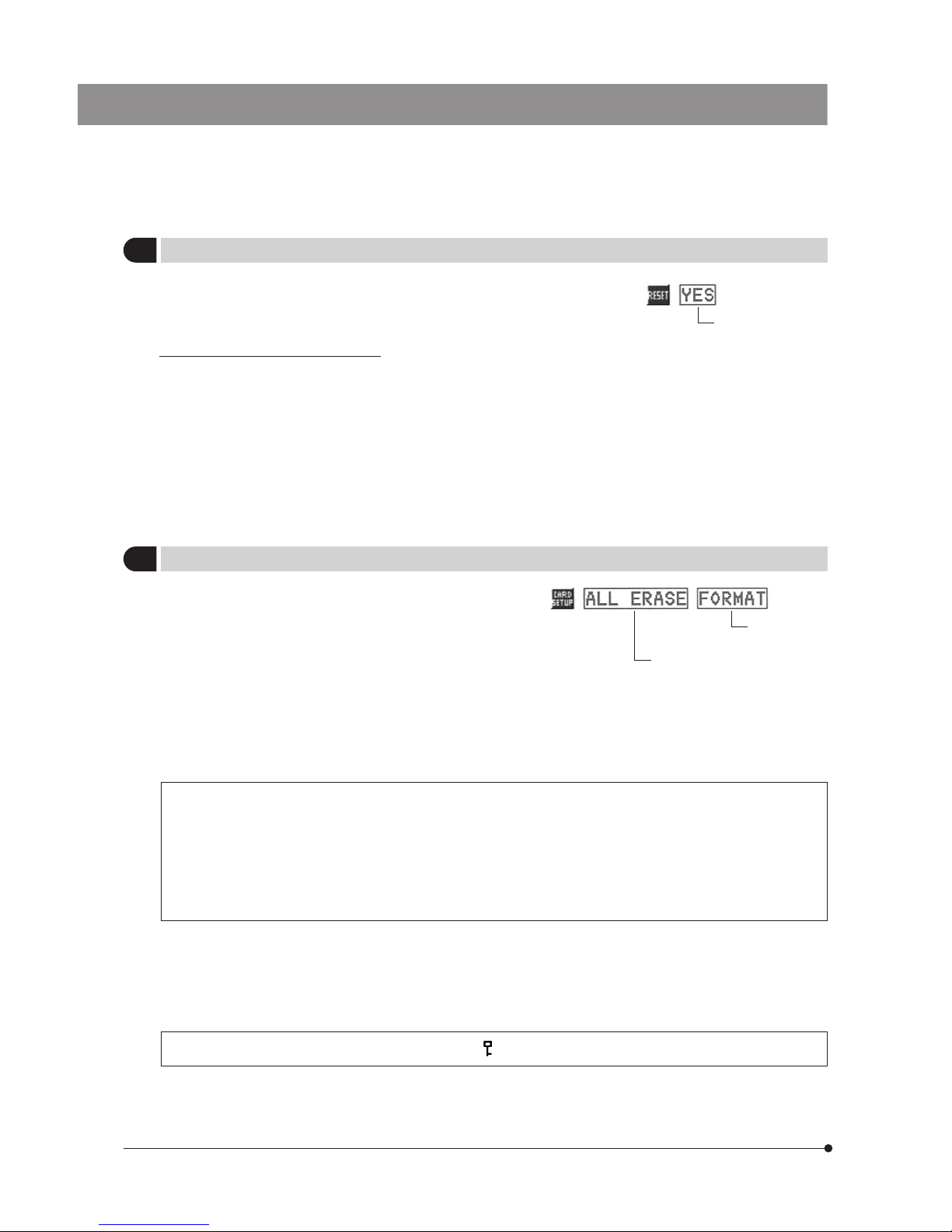
Resetting the Recording Setups
Factory setup: ----
}The setups related to recording can be reset to the factory
defaults. This function is used when you have forgotten the
setups you made previously.
To reset.
Reset items and their factory defaults
· Picture quality: HQ
· ISO: 100
· Sharpness: Normal
· White balance: AUTO
· Power supply: QUICK REV (5 sec)/SLEEP (OFF)
· Focusing area display: ON
· AE area display: OFF
· Exposure adjustment: ±0
· Metering mode: 30% average
· Focus indicator setting:OFF
}This item erases all pictures recorded in a CF card.
13
Setting the CF Card
Factory setup: ----
· After selecting the ALL ERASE icon, press the SET/OK button. When the confirmation screen appears, select “YES” if you
want to erase all pictures. Select “NO” to cancel the operation.
· All-picture erasure can erase only the non-protected pictures.
· If it is required to erase protected pictures also, unprotect them before proceeding or format the CF card
(see bellow).
· It is only the DCF format pictures that can be erased by all-picture erasure. To erase pictures in other formats,
erase them one by one.
DCF: Digital Camera image format standardized by the Japan Electronic Industry Development Association
(JEIDA).
All-picture erasure
}This item is also used to format (initialize) a CF card.
· A CF card which has been formatted by a PC or a digital camera other than the DP20 should be formatted on the DP20
before use.
· When a CF card is formatted, all data which has been recorded in it will be lost.
· During formatting, the control box accepts no other operation and the CARD access indicator LED blinks.
· When a CF card is formatted, even the protected ( ) pictures will be lost.
· After selecting the FORAMT icon, press the SET/OK button. When the confirmation screen appears, select “YES” if you
want to format the CF card. Select “NO” to cancel the operation.
Formatting
(Initialization)
#All picture erasure using ALL ERASE may take a long time
if the CF card contains a large number of pictures. In this
case, it is recommended to use FORMAT.
}To cancel erasure during ALL ERASE, press the MENU but-
ton.
Note that the pictures that have been deleted before the cancellation cannot be recovered.
Page 29
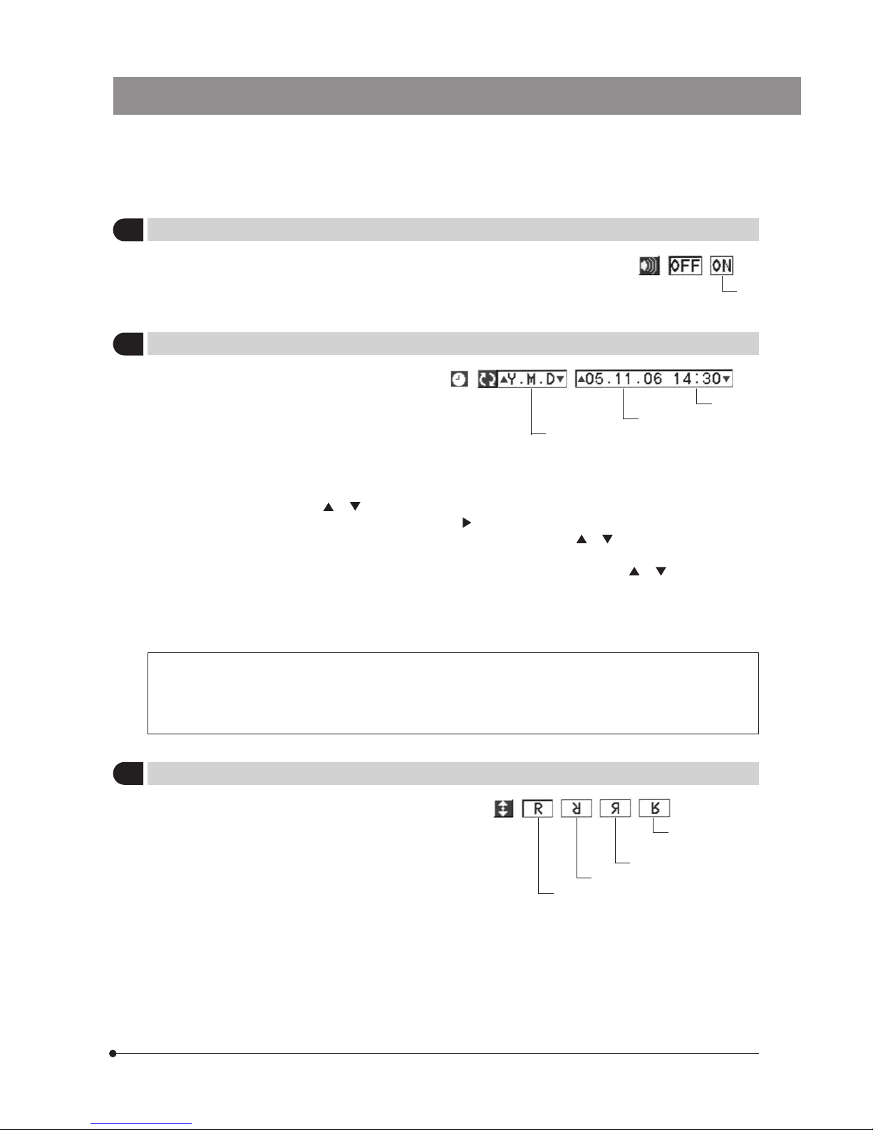
25
DP20
}The date and time can be set in the camera system.
The recording date and time are recorded together with the recorded pictures.
· Press either cross-cursor button or to select the order of the figures of year, month and day.
· When the order of figures has been set, press cursor button to move the cursor on the date position. When the figure
of “year” in the date position is displayed in green, press either cross-cursor button or to set the desired figure, and
press the SET/OK button to establish it.
· When the figure of “month” starts to be displayed in green, press either cross-cursor button or to set the desired
figure, and press the SET/OK button to establish it.
· Set the figure of “day” in the same way as above, and also press the SET/OK button to establish it.
· When the date is set, the cursor moves to the time position. Similarly set the figures of “hour” and “minute”, and also press
the SET/OK button after setting each figure.
15
Setting the Date/Time
Factory setup: ----
Order of figures
Date
Time
· When the order of the figures is changed, the order of the figures of year, month and day in the print
reservation are also changed.
· Even when the date and time are recorded with a picture, they will be altered to the processing date and
time when the picture is processed on the PC.
}This item selects the orientation of the displayed picture from
four options.
Note that this item is not available in the middle of recording.
Erect display
180° inverted display
Left/right inverted display
Up/down inverted
display
}This item selects whether or not the beep tone for warning
and other purposes is output when necessary.
ON.
14
Setting the Beep Tone
Factory setup: OFF
16
Setting the Picture Display Orientation
Factory setup: Erect display
Page 30
26
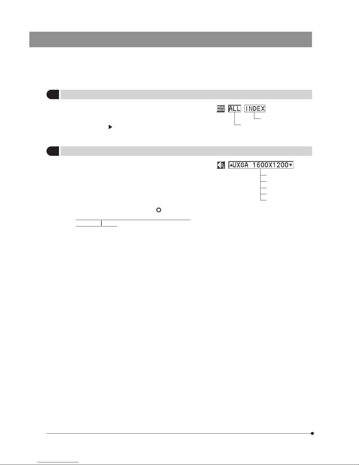
}This item selects whether the entire menu is displayed or
only the setting item icons are displayed.
Even when only the setting item icons are displayed, pressing
cross-cursor button displays the details required for the
setting operations.
Full menu display showing
all setting items
Setting item icons only
17
Setting the Menu Mode
Factory setup: ALL
}When the display in use complies with the Plug & Play
VESA DDC2B standard, the optimum display method is
set automatically. However, this menu setting item allows
you to select one of the five resolutions manually.
(Note) If the display is incapable of displaying the selected
resolution, no image is displayed, no image or only
part of image may be displayed. In this case, set the
main switch of the control box to “ ” (OFF), then
press and hold the MENU button and set the main
switch to “ ” (ON). As this starts up the display with
a resolution of 640 x 480, you can set the required
resolution in the menu.
}When the display resolution set using this menu item is smaller
than the maximum resolution of the display, the setting using
the menu is given priority.
(Example) When this menu item is set to “SXGA”, the
pictures are displayed in SXGA even when a
UXGA-compatible display is used.
}When SXGA 1280 x 960 is selected, the display resolution
becomes 1280 x 1024 and the 32 lines at the top and bottom
of the screen are displayed in black.
18
Setting the Display Resolution
UXGA 1600 x 1200
SXGA 1280 x 960
XGA 1024 x 768
SVGA 800 x 600
VGA 640 x 480
Page 31
27
DP20
· The measurement results can be erased by setting the MODE button to another mode.
· Measurement will not start when the scale display is OFF.
· When the distance measurement (or another measurement item) is selected while the image is zoomed, zooming is
canceled automatically to the 1X display. (The measurement results cannot be saved with the 2X and 4X zoom
magnifications.) To cancel measurement in the middle, press the MENU button.
· The measurement data is hidden when the zoom display is initiated. If the image is photographed under this condition,
no measurement data will be recorded in the photo. The measurement data re-appears when zooming is canceled to
the 1X display.
· Select one of the scale names “ON1” to “ON7” in which the photographing magnification is set, and press the
SET/OK button to set the scale display ON.
· Provided that the menu is not displayed and the DP20 is in a record mode, the scale names can be switched in
order from “ON1” by pressing the MENU (or MODE) button while holding the SET/OK button (press the MENU
button for switching in the descending order or the MODE button for ascending order).
(Note) It is mandatory to set the scale display (i.e. input the
photographing magnification) before starting
measurements.
Measurement can be started only when the display
resolution if UXGA 1600 x 1200 or SVGA 800 x 600.
In the “Scale display range” setting, select either
(Display scale and measurements in both display and
recorded picture) or (Display scale and measurements
only on the display screen). When you want to save
the measurement results in the recorded pictures,
select “ (Display scale and measurements in
both display and recorded picture)” before pressing the
EXPOSE button. If the focusing area, focusing indicator
and/or metering area are displayed, they are also saved
in the picture together with the measurement results.
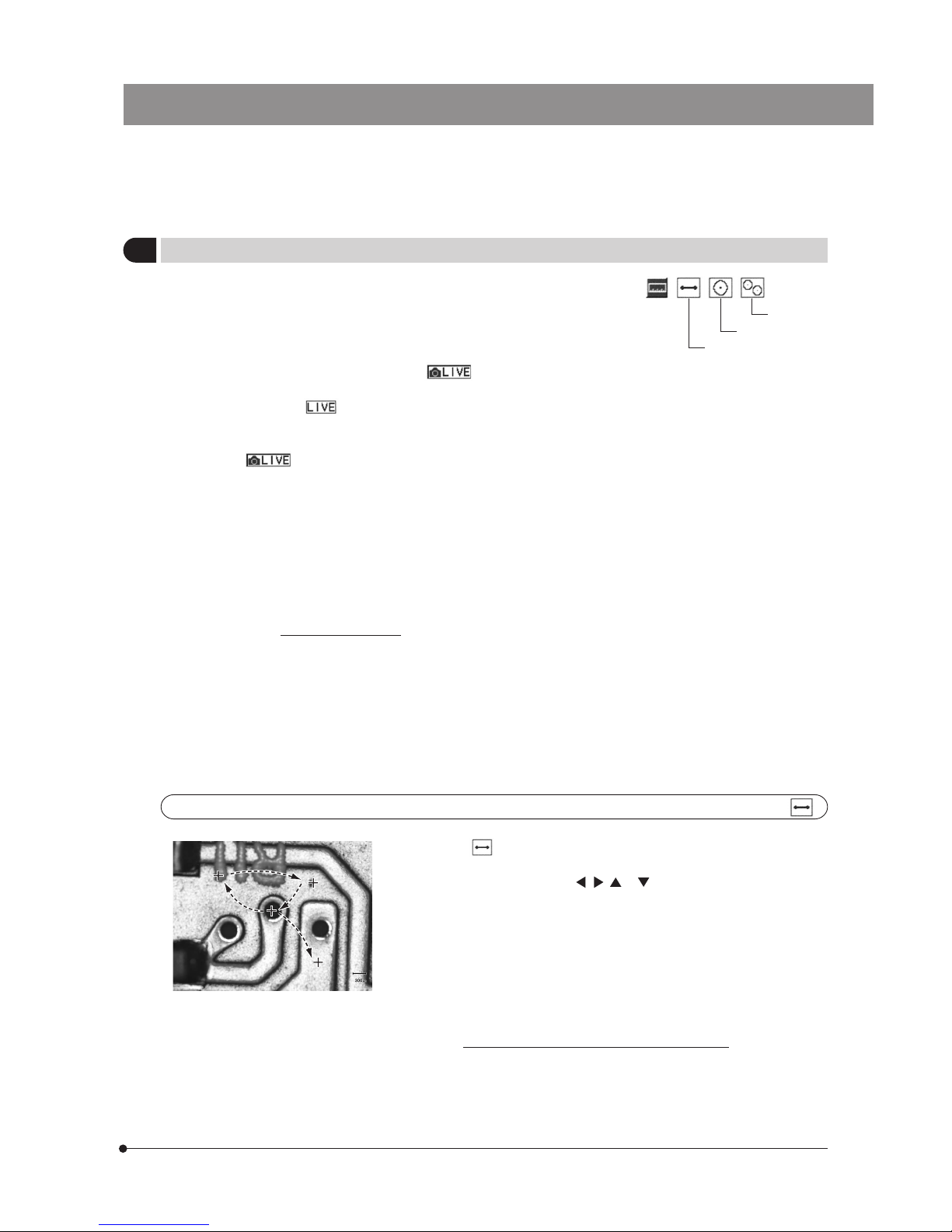
1. When is selected, the + (blue) cursor appears on the image center,
indicating that the distance measurement mode is activated.
2. Press cross-cursor button , , or to move the + cursor to the point
you want to set as the measurement start point, and press the SET/OK
button.
3. Move the + cursor to the point you want to set as the end point, and
press the SET/OK button.
4. The start and end points are connected with a line and the + cursor
returns to the image center.
5. Move the + cursor to the position you want to display the measurement
results, and press the SET/OK button.
}The maximum number of measurements is 10 including other
measurement items.
}If measurement is impossible, the + cursor turns from blue to red and no
more input is accepted. In this case, restart the procedure from the
beginning.
19
Setting the Measurements
Distance
Circle
Distance measurement
Two-Circle
Start point
Start point
End point
End point
Measurement
Measurement
results
results
Start point
End point
Measurement
results
Page 32
28
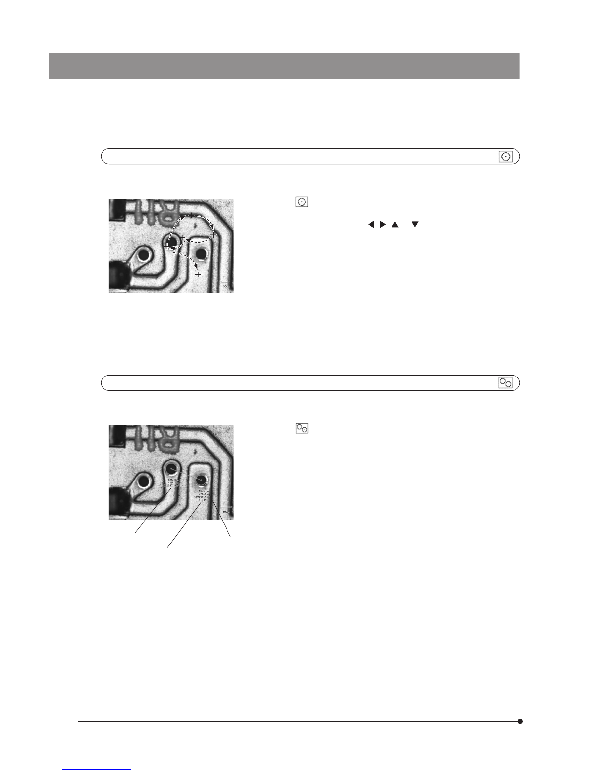
1. When is selected, the + (blue) cursor appears on the image center,
indicating that the circle measurement mode is activated.
2. Press cross-cursor button , , or to move the + cursor to the
point you want to set as the first point, and press the SET/OK button.
3. Set the second and third points in the same way as above, and press the
SET/OK button for each point.
4. A circle that passes the three points as the circumference is displayed,
and the + cursor returns to the image center.
}If the three points are set improperly for drawing a circle, the + cursor
turns from blue to red and no more input is accepted. In this case, restart
the procedure from the beginning.
5. Move the + cursor to the position you want to display the measurement
results, and press the SET/OK button.
}The maximum number of measurements is 10 including other
measurement items.
Two-circle measurement
}The two-circle measurement measures the radius, diameters and areas of two circles and the distance between their
centers.
1. When is selected, the + (blue) cursor appears on the image center,
indicating that the two-circle measurement mode is activated.
2. Perform the circle measurement procedure above for each circle.
}The distance between the centers of two circles is displayed in the
measurement results for the last circle.
}The maximum number of measurements is 10 including other
measurement items.
Circle measurement
}The circle measurement measures the radius, diameter and area of a circle that can be specified by selecting three
points.
First point
First point
Third
Third
point
point
Second
Second
point
point
First point
Third
point
Second
point
Measurement
Measurement
results
results
Measurement
results
Distance between
two circles
Second circle data
First circle data
Page 33
29
DP20
PLAYBACK FUNCTION SETUP/CONTROL (PLAY)
6-1 Operations Using the Control Box Buttons (PLAY)
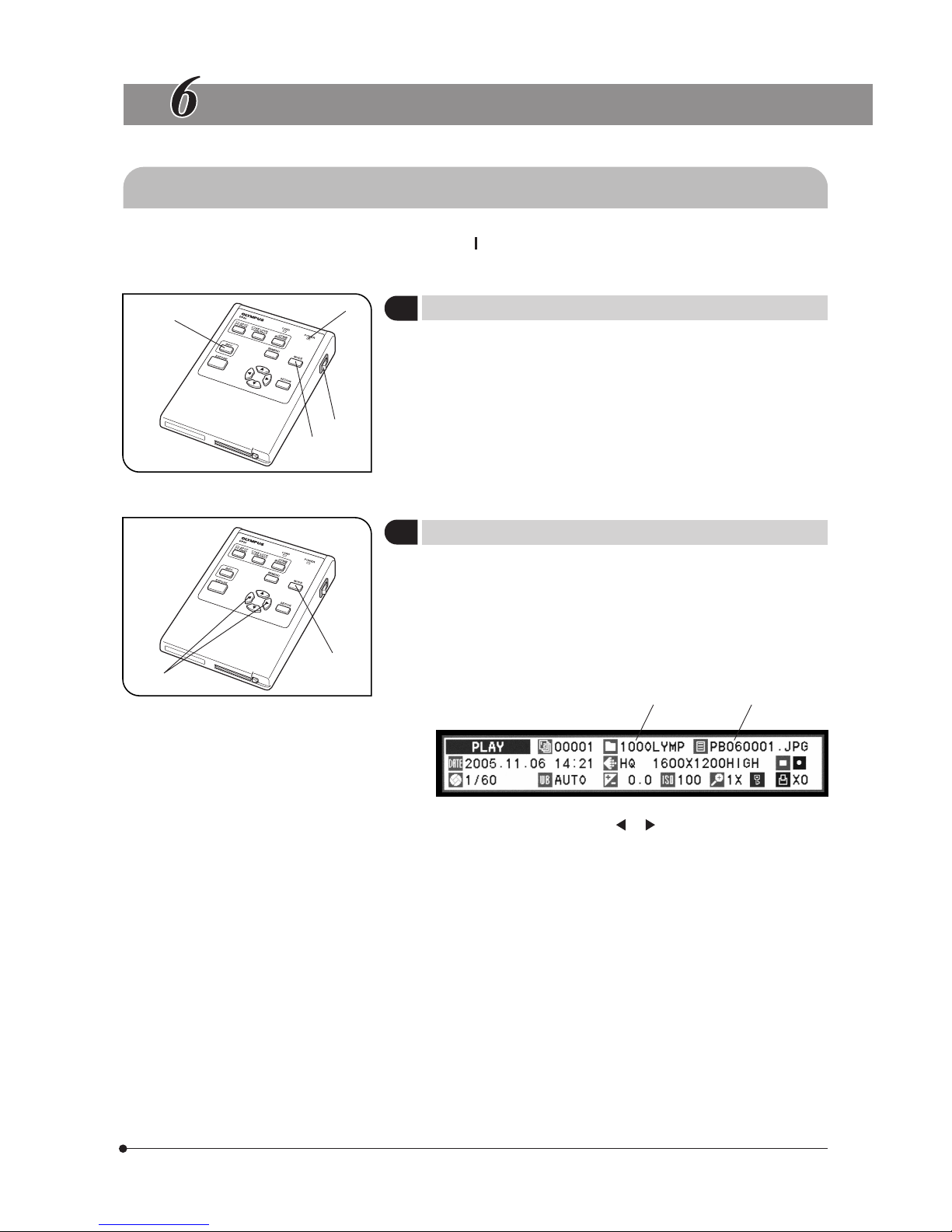
}After installing the CF card, set the main switch @ to “ ” (ON) and confirm that the POWER indicator LED ² lights up.
(The display shows an image in about 5 seconds after the indicator ² lights up.)
1. Press the INFO (recording information) button ³ to display or hide the
INFO display alternately.
To perform setups, it is required to display the INFO display.
(Factory setup: INFO display ON.)
2. When the MODE button | is pressed to select PLAY, the recording
information for playback is displayed.
}Press the MODE button @ to switch the mode between REC AUTO
(auto recording), REC MANUAL (manual recording) and PLAY (playback).
1. Select PLAY mode.
The display plays the last picture recorded in the CF card.
However, if the played picture is the index display, the picture in the
position of the green cursor is displayed.
The INFO display shows the folder name ² and file name ³.
2. Press either cross-cursor button or | to select the played picture.
(If the button is pressed on the index display, the button moves the
cursor.)
Each press of a button plays the picture located before or after the
current picture. The play speed is variable depending on picture sizes.
}It is also possible to play the pictures by advancing them frame by
frame at a set interval (1 sec., 5 sec., 10 sec. or 30 sec.) just like a
slideshow (see page 32).
1
Setting the INFO Button
(Fig. 16)
Fig. 16
1
2
3
4
Fig. 17
1
23
4
2
Setting the MODE Button
(Fig. 17)
Page 34
30
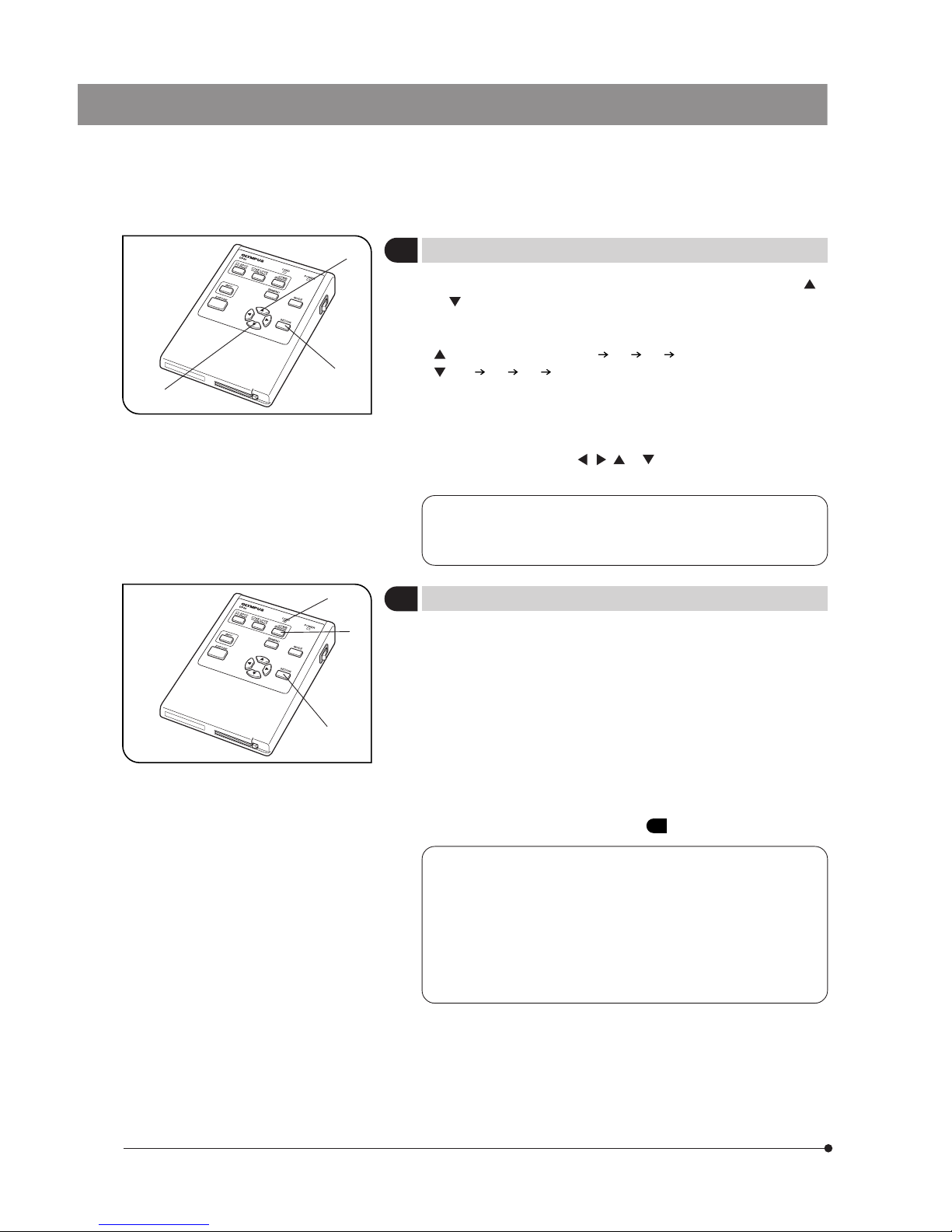
}During playback of a single picture, press either cross-cursor button @
or ² to zoom into or out of the played picture. (Factory setup: 1X)
#The display may take a long time when displaying an index display
containing a large number of pictures (about 500 or more pictures).
: Index display (40 frames) 1X 2X 4X
: 4X 2X 1X Index display
}At 2X or 4X zoom magnifications, the entire picture cannot be displayed
in the screen.
The hidden area of the picture can be viewed with zoom scrolling.
To zoom scroll on a picture, press and hold the SET/OK button ³ while
press cross-cursor button , , or . (The entire picture area can be
scrolled in this way.)
3
Zooming a Played Picture
(Fig. 18)
When a folder or file name in the CF card is altered using a PC or
a picture file is processed with application software, the file may
become unable to be played back on the DP20.
Fig. 18
1
2
3
}The following procedure is used to erase an unwanted picture.
A procedure for erasing all pictures in a CF card is also available
(see page 24).
1. Select the picture to be erased. A picture in the index display can be
selected by placing the cursor on it (using the cross-cursor buttons).
2. Press the ERASE button @. The display will show the erasure confirmation
message (YES, NO), with the green cursor placed on “YES”.
3. To erase the picture, press the SET/OK button ². The card access
indicator LED ³ blinks and the selected picture is erased.
}To cancel erasure, select “NO” and press either the SET/OK button ² or
ERASE button @.
#A picture protected as described in
5 below cannot be erased.
· Even when pictures are protected, they are erased when the CF
card is formatted.
· When a file associated with the picture to be erased (main
picture), such as a thumbnail file, has been recorded and any of
the associated files is protected, the protected file cannot be
erased.
· The above procedure makes it possible to erase a file in the
DCF format as well as other format.
Fig. 19
1
2
3
4
Erasing a Single Picture (ERASE)
(Fig. 19)
Page 35
31
DP20
5
Protecting a Picture (PROTECT)
(Fig. 20)
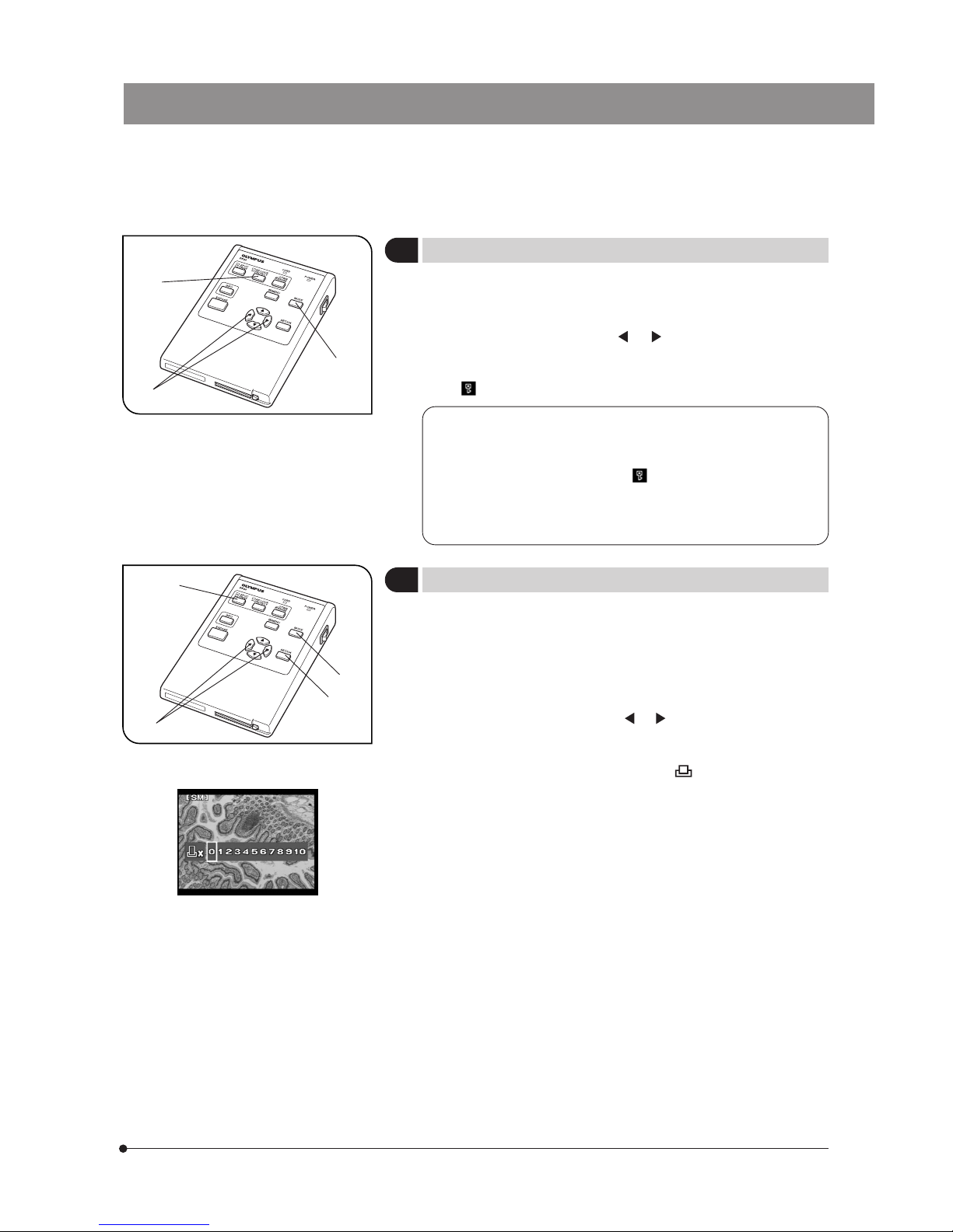
}The following procedure is used to protect a recorded picture against
accidental erasure.
1. Press the MODE button @ to select PLAY.
2. Press either cross-cursor button or ² to select the picture to be
protected.
3. Press the PROTECT button ³. The picture being displayed is protected
and (protect marking) is shown in the INFO display.
· It is also possible to protect a picture in the index display. In this
case, move the green frame cursor on the index picture to be
protected.
· When the protected picture file ( ) is downloaded in a PC, the
downloaded file is given the read-only attribute.
· A protected picture can be unprotected by displaying it and pressing
the PROTECT button again.
}Print reservation/cancellation of all picture frames, date printing and time
printing can be set by means of the menu (see pages 32 & 33).
1. Press the MODE button @ to select PLAY.
2. Display the picture to be subjected to print reservation, and then press
the PRINT reservation button ².
3. The display shows the display for specifying the number of printouts.
Press either cross-cursor button or ³ to place the green frame
cursor on the desired number of printouts and press the SET/OK
button |.
4. The printing of the picture is reserved and “ x <Number of printouts>”
is shown in the INFO display.
}To cancel a print reservation, set the number of printouts to 0.
Fig. 20
1
2
3
Fig. 21
1
2
3
4
6
Making a Print Reservation (PRINT)
(Fig. 21)
Page 36
32
6-2 Operations Using the Menu (PLAY)
}The basic flow of setups is identical to the description in section 5-2-1 (see page 17).
· Press the MODE button to select PLAY.
· Press the MENU button to display the Menu.
· After setting, be sure to press the SET/OK button to establish the setting.
1
Setting Auto Playback Display
Factory setup: 5 sec.
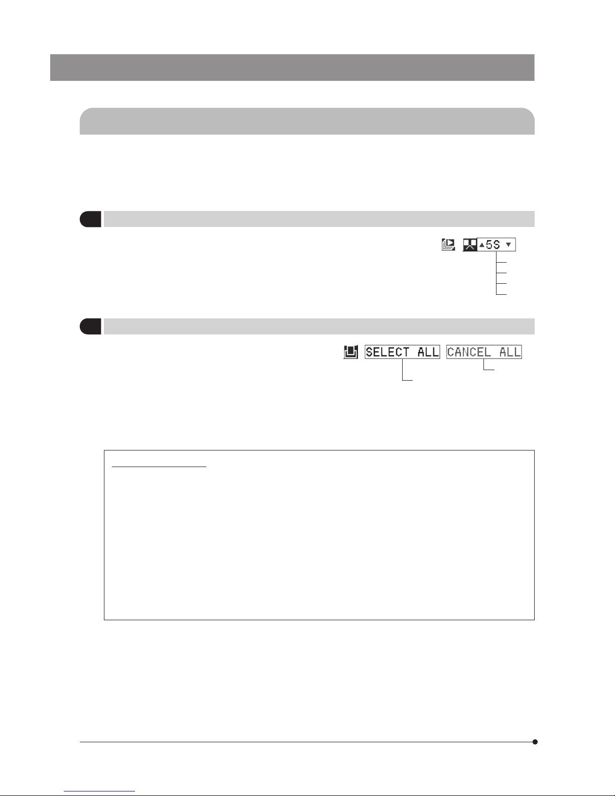
}This item displays pictures by advancing them frame by
frame at the set interval, just like a slide show.
· To stop automatic playback in the middle, press the MENU
button.
· When automatic playback is started in the index display,
pictures are played index by index.
1 sec.
5 sec.
10 sec.
30 sec.
2
Making All-Picture Print Reservation
}The PRINT button (see page 31) can also be used to make
print reservation for all of the pictures recorded in the CF card
(one printout per frame).
When all-picture print reservation is made, the number of
printouts specified in “Making a Print Reservation” (page 31)
becomes invalid. Similarly, when option “CANCEL ALL” in this
item is selected to cancel the all-picture print reservation, the
number of printouts is set to 0 including that specified in
“Making a Print Reservation”.
All-picture print reservation
Cancel All
Note on print reservation
}DPOF: Format for automatic printout on a printer.
The following methods are available for printing pictures which have been recorded with the DP20 camera system
and in a CF card.
#Direct printing with the printer connected to the DP20 via a USB cable is not possible.
· The number of printouts and recording date/time can be recorded with pictures which have been recorded
in a CF card with the DP20 (Print reservation). When a CF card containing print reservations is inserted in a
DPOF compatible printer, the printer prints the specified pictures automatically even when you do not perform
any print setting on the printer.
In addition to printing on a DPOF printer, if the CF card is brought to a store providing print service using a
DPOF system, the pictures with print reservations can be printed automatically without any instruction required.
· When pictures are downloaded in a PC using the DP20-DRV image downloading software or a PC card, they
can be printed out a the printer connected to the PC.
Print reservation and print output may not work properly with certain printers.
Page 37
33
DP20
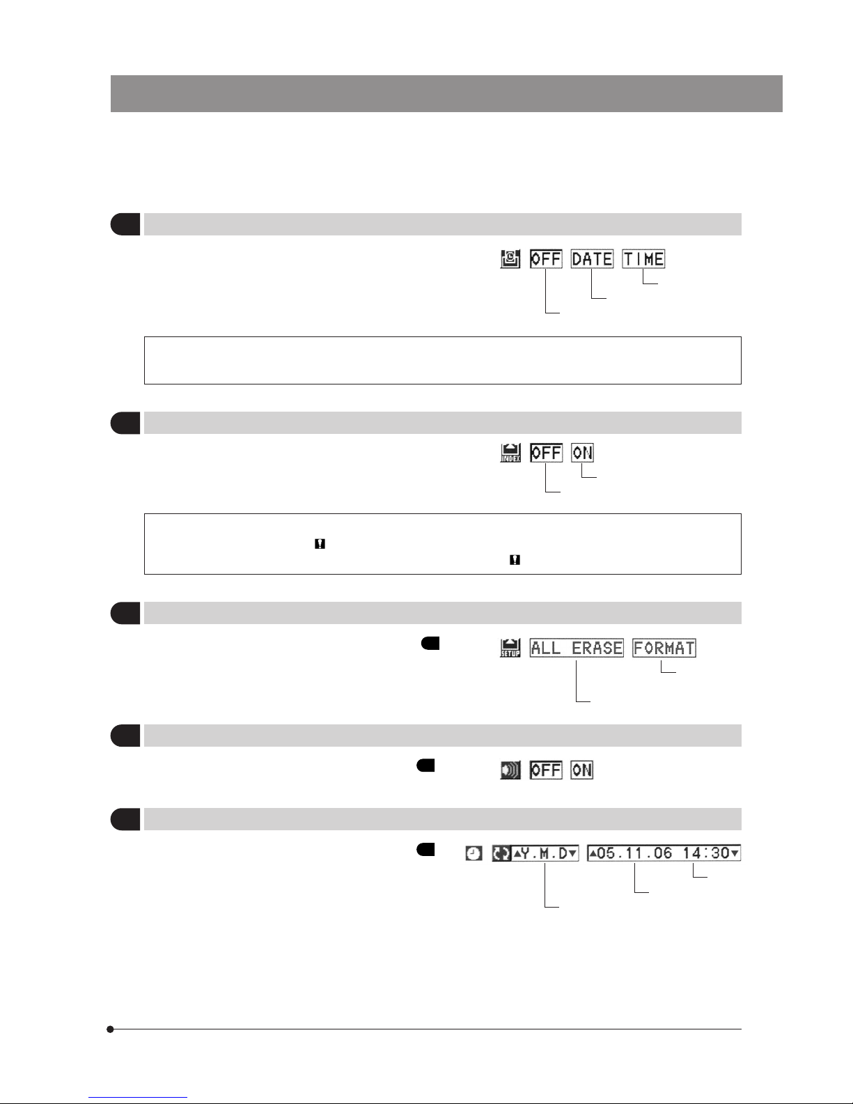
}The recording date and/or time can be printed on each picture
for which print reservation is made.
No date/time print
Print date.
Print time.
The time/date printing position and font are variable depending on the printer specifications. For details, refer
to the instruction manual of your printer.
}When making a print reservation, it is possible to specify
printing of all pictures in the CF card in the form of an index
print.
Cancel
Reservation ON
· Pictures recorded after index print reservation are not included in the index print. If there are non-reserved
pictures in a CF card, the “ ” marking appears next to menu item “CARD INDEX”. To make index print
reservation of all pictures, restart the setting from the beginning. “ ” will disappear after this.
}The same setting operation as that described in
13
of
“Operations Using the Menu (REC)” (page 24) is available.
All-picture erasure
Formatting
(Initialization)
}The same setting operation as that described in 14 of
“Operations Using the Menu (REC)” (page 25) is available.
3
Setting the Date/Time Printing
4
Making Index Print Reservation
5
Setting the CF Card
Factory setup: ----
6
Setting the Beep Tone
Factory setup: OFF
Order of figures
Date
Time
7
Setting the Date/Time
Factory setup: ----
}The same setting operation as that described in 15 of
“Operations Using the Menu (REC)” (page 25) is available.
Page 38
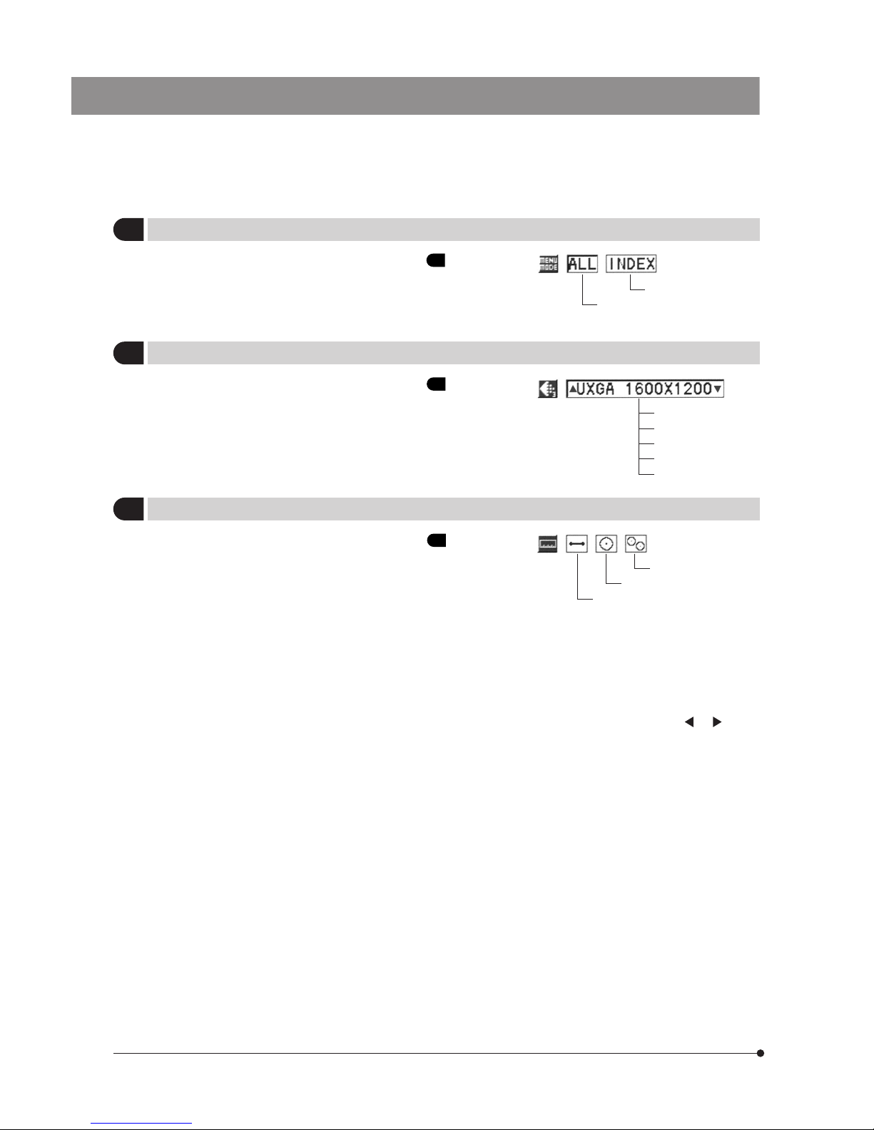
34
}The same setting operation as that described in 17 of
“Operations Using the Menu (REC)” (page 26) is available.
Full menu display showing all
setting items
Setting item icons only
}The same setting operation as that described in 18 of
“Operations Using the Menu (REC)” (page 26) is available.
}The same setting operation as that described in 19 of
“Operations Using the Menu (REC)” (page 27) is available.
Distance
Circle
Two-Circle
(Notes)
· Due to the use of played pictures, the measurement results are incorrect if the photographing magnification has
not been input during photographing and recording.
Also, the subjects photographed with the scale display OFF cannot be measured.
· Measurements are possible only with pictures photographed with the SHQ - TIFF picture quality mode. They are
neither impossible with the index display pictures.
· When you want to save the measurement results in the recorded picture, press either cross-cursor or button
(or the MODE button).
After the above button is pressed, the confirmation message (SAVE/CANCEL) is displayed the next time you
attempt to view another display (or switch the mode). Select either option with a cross-cursor button and press
the SET/OK button.
After the measurement results have been saved, the display you attempt to view appears (or the MODE button is
switched to another mode).
}When the focusing area, focusing indicator and/or metering area, they are also recorded in the picture together with the
measurement results.
8
Setting the Menu Mode
9
Setting the Display Resolution
10
Setting the Measurements
UXGA 1600 x 1200
SXGA 1280 x 960
XGA 1024 x 768
SVGA 800 x 600
VGA 640 x 480
Page 39
35
DP20
PICTURE DOWNLOADING IN A PERSONAL COMPUTER
Recommended operating environment
1) Operating system : Microsoft
R
Windows R XP SP1/XP SP2/2000 SP4
2) RAM : 128 MB or more
3) HDD idle capacity : 50 MB or more
4) PC : IBM PC/AT compatible computer*
5) I/O devices : USB 2.0 port, CD-ROM drive
6) CPU : Intel
R
Pentium III R processor, 500 MHz equivalent or faster
7) Display : Resolution 800 x 600 or better,
full-color display (24-bit) or better.
8) Display adapter : Windows support required.
9) Pointing device : Mouse, etc.
10) Keyboard : Windows support required.
*Operation on all PCs is not guaranteed.
Trademark information
Windows is a registered trademark of Microsoft Corporation.
All other brand and product names are registered trademarks or trademarks of their respective owners.
7-1 Before Software Installation
Before Installation
When the OS is Windows
R
XP
The application software cannot be installed unless the user account is registered as “computer administrator”.
If the user account is registered as a “Restricted account”, change it to the “Computer administrator” account.
(For the user account registration, refer to the instruction manual for your PC.)
When the OS is Windows
R
2000
Log on as a user with the Administrator authority and make sure that you have the access rights to the following locations.
(For the access rights, refer to the instruction manual for your PC.)
· Folder for installing this software.
· Windows System folder and System registry.
· The software may not be installed properly when a USB device such as USB mouse or USB flash drive is connected to
your PC.
· The DP20 may not function properly if you start your PC with the DP20 connected. Should that be the case, disconnect
the DP20 and then connect it again.
Page 40
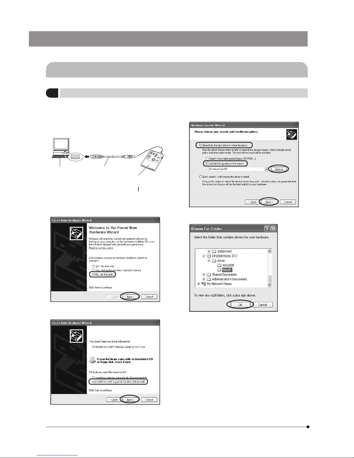
36
7-2 Installation of Device Driver
1
When the OS is Windows XP
1. Exit from all other applications that are running.
2. Place the DP20-DRV image downloading software CD-ROM
in the CD-ROM drive.
3. Connect the control box to a PC using the provided USB
2.0 cable.
4. Set the main switch of the control box to “ ” (ON).
5. When the [New Hardware Detection Wizard] is displayed
automatically, check [No, not this time.] and click on the
[Next] button.
7. Check [Search for the best driver in these locations.], check
[Include this location in the search.] only (uncheck [Removal
media] if it is checked), and click on the [Browse] button.
6. Check [Install from a list or specific location(Advanced).] and
click on the [Next] button.
· Select [My Computer] - [CD-ROM drive] - [driver] - [Win XP],
and click on the [OK] button.
[CD-ROM drive: \driver\Win XP] is displayed in the dialog
box of step 7. Now click on the [Next] button.
PC
To USB 2.0 port
USB 2.0 cable
To USB 2.0 connector
Control box
Page 41
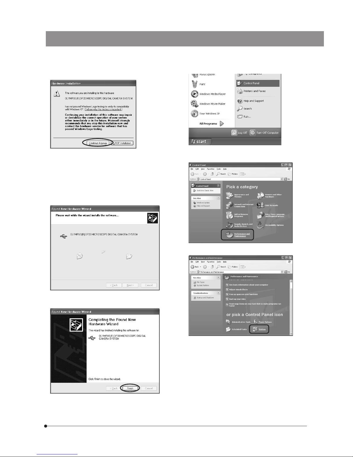
37
DP20
8. When a dialog box as shown below is displayed, click on
the [Continue Anyway] button because this will not hinder
operation.
9. The driver installation starts.
11. Click on the [Start] button. When the [Start] menu is displayed,
select [Control panel].
13. Select [System].
(Note) When Olympus software is recognized, the message
is displayed to notify that the software is not
authorized by Microsoft. But you can continue
installation because this does not present any
special problem. Microsoft executes certification
procedures for PC and peripherals through an
organization named WHQL, but the present product
has not been certified for the present.
10. When the following dialog box is displayed in a while, click
on the [Finish] button. Now the driver has been installed.
Next, make sure that the driver has been installed
successfully.
12. When the [Control Panel] dialog box opens, select
[Performance and Maintenance].
Page 42
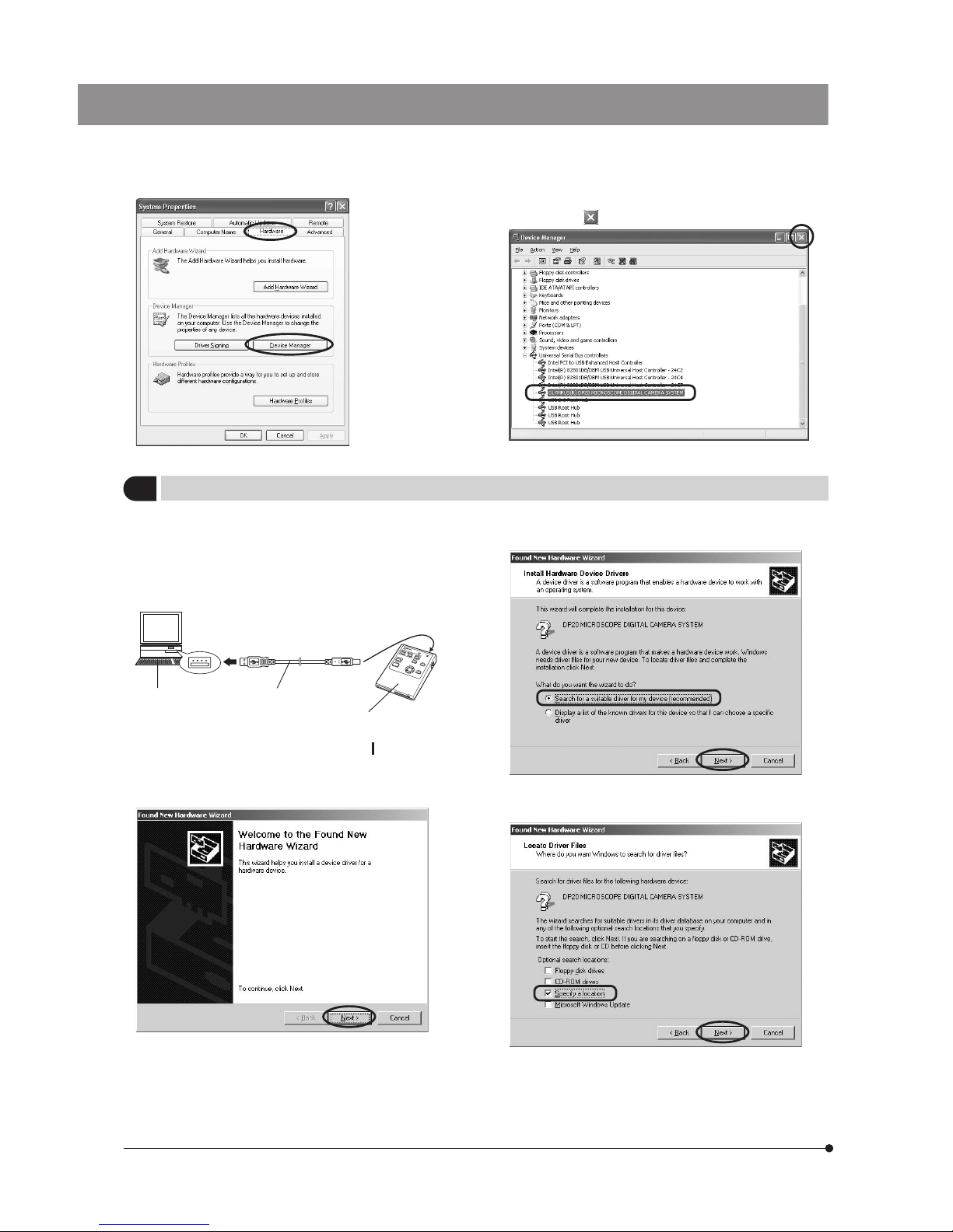
38
14. When the [System Properties] dialog box opens, select the
[Hardware] tab and click on the [Device Manager] button.
15. If the driver has been installed successfully, “OLYMPUS(R)
DP20 MICROSCOPE DIGITAL CAMERA SYSTEM” should
be displayed below “USB controller”. After checking this,
click on the [ ] button.
2
When the OS is Windows 2000 SP4
1. Exit from all other applications that are running.
2. Place the DP20-DRV image downloading software CD-ROM
in the CD-ROM drive.
3. Connect the control box to a PC using the provided USB
2.0 cable.
4. Set the main switch of the control box to “ ” (ON).
5. When the [New Hardware Detection Wizard] is displayed
automatically, click on the [Next] button.
6. Check [Search for a suitable driver for my device
(recommended).] and click on the [Next] button.
7. Check [Specify a location] (uncheck other checkboxes if
any of them is checked) and click on the [Next] button.
PC
To USB 2.0 port
USB 2.0 cable
To USB 2.0 connector
Control box
Page 43
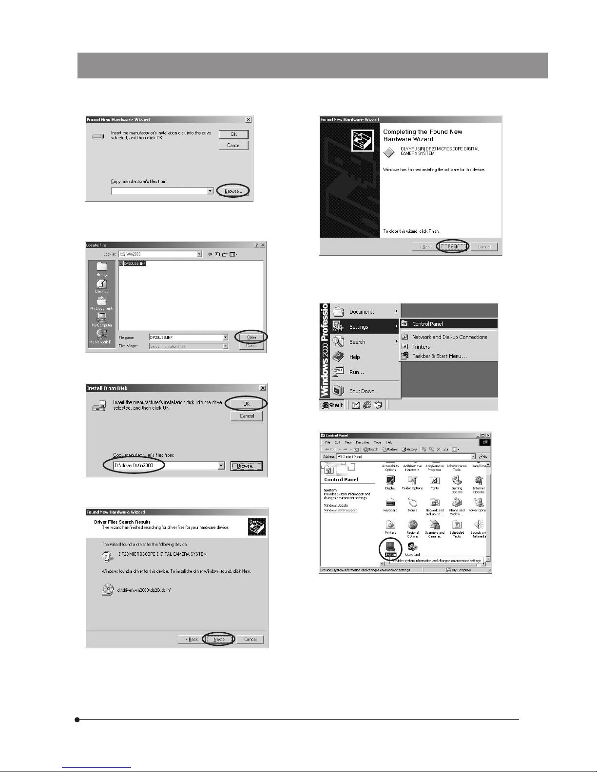
39
DP20
8. Click on the [Browse] button.
10. Confirm that [Manufacturer’s file copy source] is set to “CDROM drive: \driver\Win2000” and click on the [OK] button.
12. Click on the [Finish] button. Now the driver has been installed.
13. Click on the [Start] button. When the [Start] menu is displayed,
select [Settings] - [Control panel].
14. When the [Control Panel] dialog box opens, select [System].
9. When the [Locate File] dialog box opens, select “CD-ROM
drive: \driver\Win2000\DP20USB.INF” and click on the [Open]
button.
11. Click on the [Next] button. This starts installation of the driver
software.
Next, make sure that the driver has been installed
successfully.
Page 44
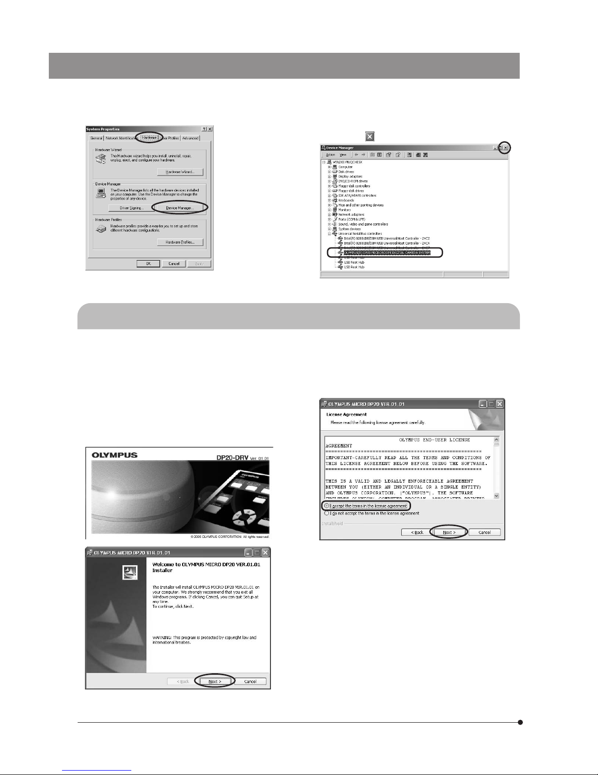
40
15. When the [System Properties] dialog box opens, select the
[Hardware] tab and click on the [Device Manager] button.
16. If the driver has been installed successfully, “OLYMPUS(R)
DP20 MICROSCOPE DIGITAL CAMERA SYSTEM” should
be displayed below “USB controller”. After checking this,
click on the [ ] button.
7-3 Installation of Application Software
}Complete the installation of the device driver before proceeding to the installation of the image downloading software.
1. Place the DP20-DRV image downloading software CD-ROM
in the CD-ROM drive.
2. Click on the [Start] button in the Windows taskbar.
3. Select [Run].
4. Enter the following command and click on the [OK] button.
CD-ROM drive: \setup.exe
5. Before proceeding to installation, exit from all running
applications. Then click on the [Next] button.
6. Read the displayed License Agreement. If you agree with it,
check “I accept the terms in the license agreement.” and
click on the [Next] button.
Page 45
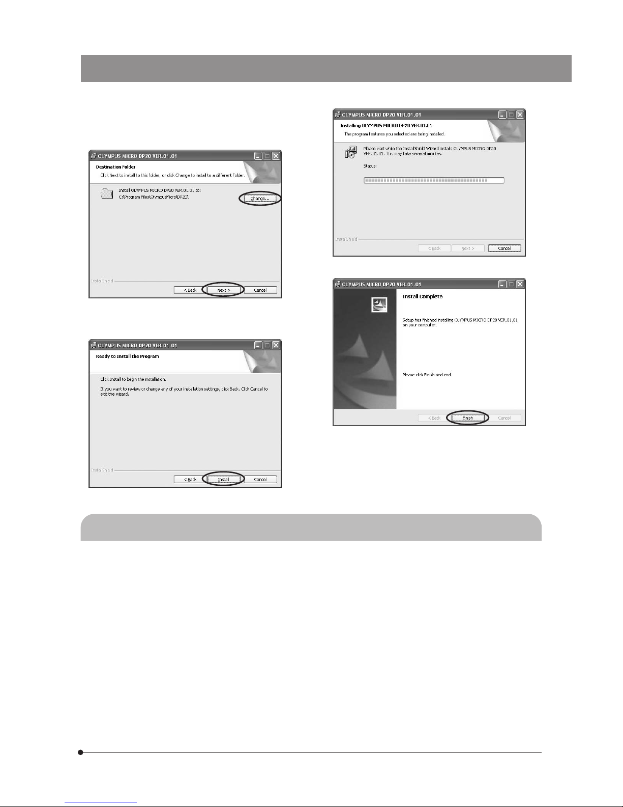
41
DP20
7. The [Choose Destination Folder] window appears. If you
want to change the installation destination, click on the
[Change...] button and specify the new installation
destination. Then click on the [Next] button.
10. Take out the CD-ROM.
Now the application software has been installed.
7-4 Software Uninstallation (Deletion)
1. Click on the [Start] button on the taskbar. When the [Start] menu is displayed, select [Settings] - [Control Panel].
2. When the [Control Panel] dialog box is displayed, select [Add/Remove Programs]. This opens the [Add/Remove Programs
Properties] dialog box.
3. Select [DP20] from the list of installed software and click on the [Change/Remove] button. When the confirmation
message is displayed, click on the [OK] button.
4. After completion of uninstallation, the [Add/Remove Programs Properties] dialog box is displayed again. Click on the
[OK] button.
8. The [Start Copying Files] window appears. When the
installation is ready, click on the [Install] button. This starts
installation of the application software.
9. When the installation completes, click on the [Finish] button.
Page 46
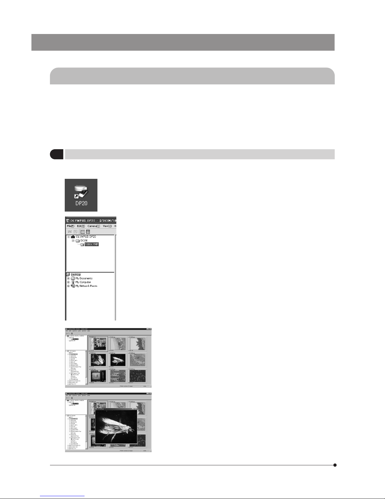
42
7-5 Computer Control Operation Procedure
}The software can be used to view the pictures shot with the DP20 or load pictures recorded in a CF card into a computer.
For how to use the software, start the application software, open the [Help] menu, select [Help] and read the displayed
instructions.
The software operating instructions can also be found in file “DP20.pdf” (Adobe Acrobat file) located in the same folder
as the folder containing the software.
# If you attempt to view a picture that is shot using a camera other than the DP20 or edited using a computer, the
software may not be able to display the picture or the software or the computer may malfunction.
1
Playing Pictures in a CF Card
}Pictures recorded in the CF card installed in the control box can be viewed on the PC screen.
1. Start the software installed in the PC.
2. Click on the [My Camera] icon.
The list of recorded pictures appears.
3. Place the cursor on the picture you want to view and double-click on it.
The selected picture is magnified and displayed.
· The reduction ratio of an image when it is displayed is determined by its
resolution and option settings.
· When an image that has been dragged and dropped in the Recycle Bin
remains in the thumbnail display, select [Refresh (R)] from the [View (V)]
menu.
Page 47
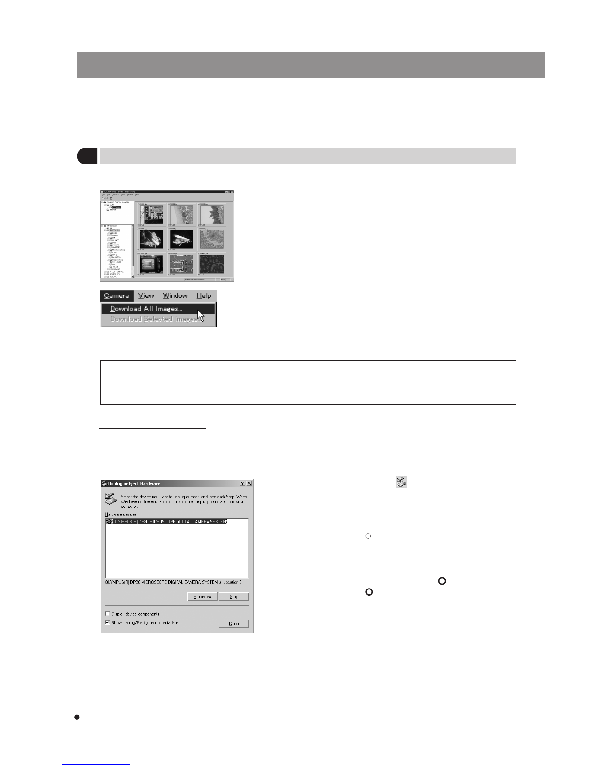
43
DP20
1. Double-click on the disconnect icon on the taskbar of the PC screen.
2. When the hardware device list is displayed, select “OLYMPUS(R) DP20
MICROSCOPE DIGITAL CAMERA SYSTEM” and click on [Stop]. Hereafter,
disconnect the hardware device by following the instructions given by
the dialog boxes to be displayed successively.
When the OS is Windows
R
2000, the hardware device can also be
disconnected by opening the [Control Panel], selecting [Add/Remove
Programs] and then selecting “OLYMPUS(R) DP20 MICROSCOPE DIGITAL
CAMERA SYSTEM”.
3. Set the main switch of the DP20 control box to “ ” (OFF) and then the
power switch of the PC to “ ” (OFF).
4. Unplug the USB 2.0 cable from the DP20 control box.
5. Unplug the other end of the USB 2.0 cable from the PC.
2
Downloading Pictures in the CF Card to the PC
Pictures recorded in the CF card installed in the camera system can be downloaded in the PC.
1. Start the software installed in the PC.
2. Select [Camera] in the menu bar then select [Download All Images ].
All pictures in the CF card are downloaded from it to the PC.
Only the selected pictures can be loaded in the computer by selecting
the desired pictures in advance.
For details, refer to the description in [Help].
The pictures loaded in the PC can be viewed with other application software than the provided software, for
example graphic software handling JPEG/TIFF (PaintShop Pro, PhotoShop, etc.) or Internet browser software
(Netscape Communicator, Microsoft Internet Explorer, etc.).
PC disconnection procedure
}To prevent malfunction of the DP20 and/or PC, always use the following procedure when disconnecting the DP20 and
PC. Also confirm that execution of any processing on the DP20 and PC has completed before proceeding to the
disconnection.
(Refer to [Help] for details.)
Page 48
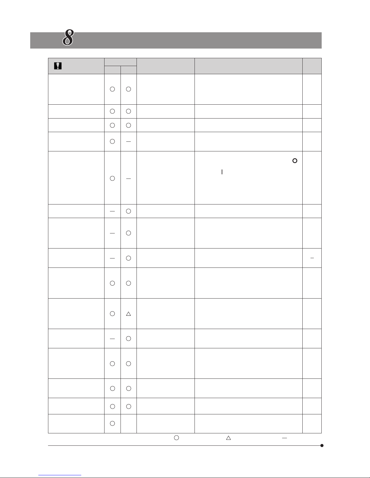
44
ERROR MESSAGE LIST
Error Message
Mode
Warning Details Treatment
Ref.
Page
REC PL AY
CARD ERROR Cannot record, play or
erase pictures.
Insert the CF card properly. If the warning recurs,
format the CF card. Note that formatting results
in erasing all of the picture and document files
in the CF card. If formatting is impossible, the CF
card is unusable.
NO CARD CF card is not inserted.
Insert a CF card.
UNFORMATTED CARD
CF card needs
formatting.
Insert a CF card.
Format the CF card.
CARD FULL CF card is full and does
not have remaining
capacity.
Use another CF card, erase unwanted pictures,
or download existing pictures to the PC then
erase all pictures in the CF card.
NO CAMERA HEAD Ca mera head is not
connected.
Connect the camera head properly as follows:
First set the main switch of the control box to “ ”
(OFF), connect the camera head, and set the main
switch to “ ” (ON) again.
If the camera head is connected while the control
box is kept ON, the camera head will not be
recognized.
Picture playback in PLAY mode is possible even
when the camera head is not connected.
NO PICTURE No picture is recorded so
playback is impossible.
Insert a CF card containing recorded pictures.
BAD PICTURE
Playback of selected frame
failed. Other operations are
accepted.
Insert the CF card properly. If the warning recurs,
format the CF card. Note that formatting results
in erasing all of the picture and document files
in the CF card. If formatting is impossible, the CF
card is unusable.
CANNOT OPEN FILE Picture file cannot be
opened with the DP20.
A picture recorded using another digital camera
should be played on the digital camera used for
recording it.
CAMERA DAMAGED
xxxx
The DP20 may be failed. Unplug and plug the AC adapter again. If the
warning recurs, note the error code and contact
Olympus.
The error code refers to the 4-digit number shown
in place of “xxxx”.
NEED A SCALE ON Measurement cannot be
started because the
scale display is OFF.
Set the scale display ON before measurements.
Measurements of played picture reflect the scale
display set in recording, but it is impossible if the
picture has been displayed with the scale display
set to OFF.
TIFF ONLY Measurement cannot be
started because the picture format is not TIFF.
Measurement of played picture is possible only
when it is recorded in the TIFF format
SAVE THE PICTURE
Number of measurements
have reached the maximum limit so it is necessary to save the picture.
The maximum number of measurements per picture is 10. The picture should be saved after it.
If “Scale display range” is set to LIVE (Display
only on the display screen.), the measurement
results are not saved.
RESOLUTION ERROR
Measurements cannot be
started because the display
resolution is inappropriate.
Set to a measurement-compatible display resolution (UXGA 1600 x 1200 or SVGA 800 x 600).
SINGLE FRAME ONLY
Measurements cannot be
started on the index display.
Display only the measurement-target picture frame.
11,24
11
24
30
8
29
11,24
21
9
34
27
26
27
: May be displayed. : Depends on picture. : Not displayed.
SET TO 1X AGAIN
During measurement,
zoom shooting is not
possible.
Shoot with the 1X display.
27
X
Page 49
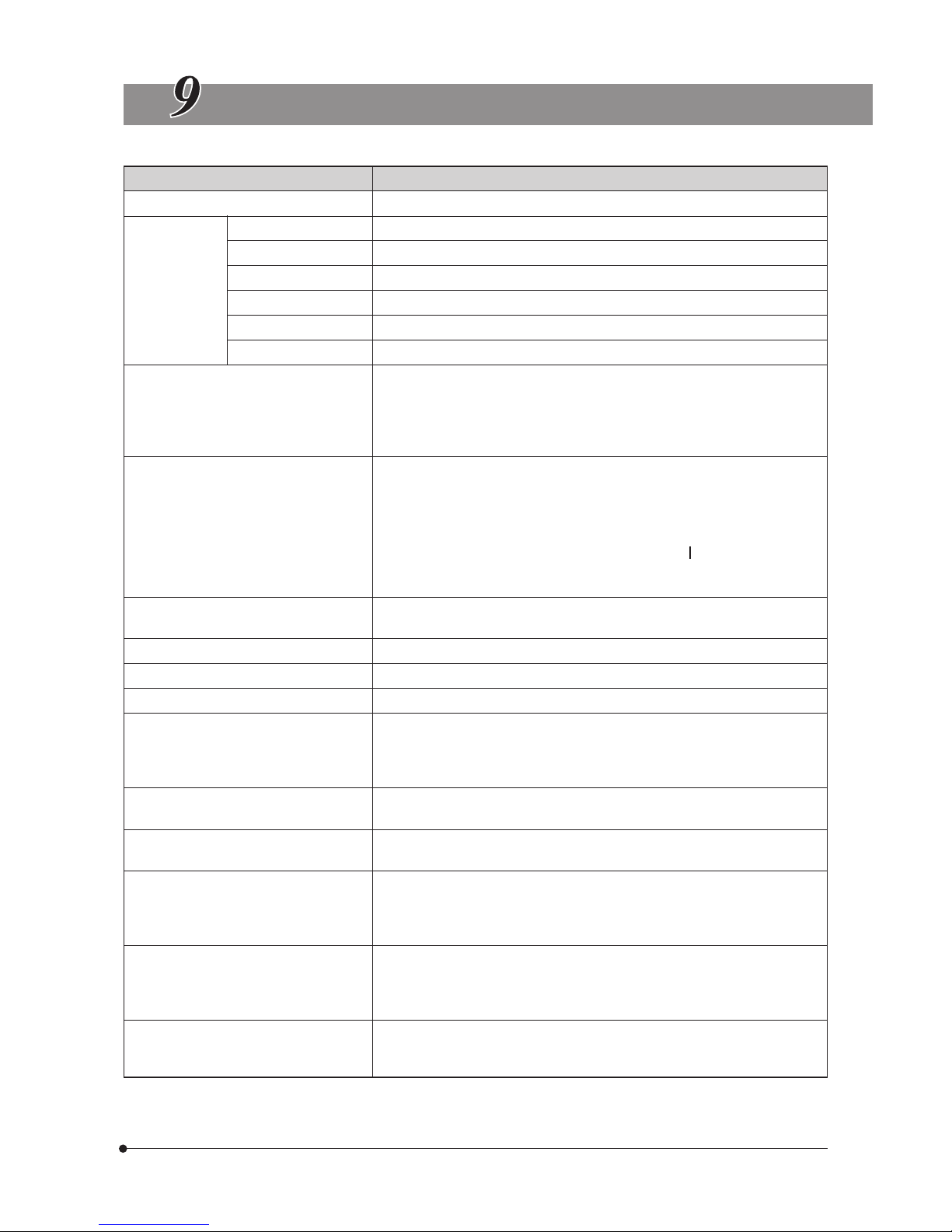
45
DP20
SPECIFICATIONS
Item Specifications
System Composed of a C-mount CCD camera unit and a control box.
Image pickup
device
Size 1/1.8-inch color CCD
Effective pixels 2.01 million (Total 2.11 million pixels)
Scan method Progressive scanning
Color filters RGB primary-color on-chip filters
Image capturing area 7.04(H) x 5.28(V) mm, diagonal length 8.8mm
Max. recording pixels 1.92 million (1600 x 1200)
Image sizes (recording pixels) and file
formats
}The JPEG file capacities refer to the
maximum values.
SHG (TIFF): 1600 x 1200 (Approx. 5760 kB)
SHQ (JPEG): 1600 x 1200 (Approx. 2140 kB max.)
HQ (JPEG): 1600 x 1200 (Approx. 720 kB max.)
SQ1 (JPEG): 1024 x 960 (Approx. 1365 kB max.)
SQ2 (JPEG): 1024 x 960 (Approx. 460 kB max.)
Compatible display resolutions
1600 x 1200
1280 x 1024 (Display area: 1280 x 960)
1024 x 768
800 x 600
640 x 480
}Hold the MENU button while set the main switch to “ ” (ON) to reset to 640 x
480.
Plug & Play (VESA GGC 2B standard)
Recording medium Compact Flush (CF card Type I)
}Recommendations: SanDisk or Lexar CF card (max. capacity 4G bytes)
Camera mount C-mount
ISO speed selection 100, 200, 400
Photometering methods Central 2.5% or central 30% average
AUTO
MANUAL
With AE LOCK (AUTO mode only).
Exposure adjustment: ±2 EV in 1/3 EV steps (AUTO mode only).
Exposure time AUTO: 2 to 1/20,000 sec.
MANUAL: 8 to 1/20,000 sec.
Successive photographing Maximum 4 pictures at minimum 1 sec. intervals.
}Every single press of the EXPOSE button records one picture.
Picture display speed (frame rate)
Live image: Display rate max. 15 frames/sec. (display pixels 1600 x 1200),
Display magnifications 1X, 2X (electronic zooming), 4X (electronic
zooming).
Recorded pictures: Display magnifications: Index display, 1X, 2X, 4X
Exposure control
Input/output connectors DC input: Main power supply.
Data I/O: USB 2.0.
Display output: Analog RGB, mini D-SUB 15-pin.
CF card slot: Type I.
Scale display Scale display ON/OFF.
Available magnifications: 00.01X to 9999.99X.
}Up to 7 magnifications can be set.
Page 50
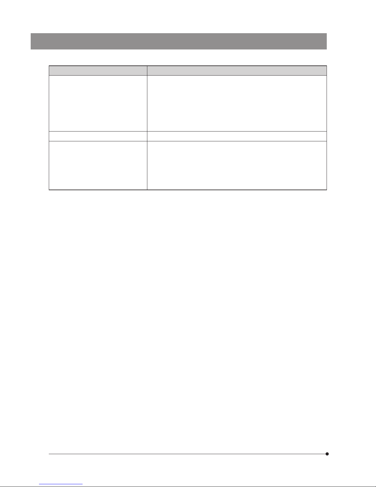
46
Measurements Distance (distance between two points),
Circle (radius, diameter and area of a circle),
Two-Circle (radii, diameters, areas and distance between the centers of two circles).
}Measurements are possible under the following conditions.
Display resolution: 1600 x 1200 or 800 x 600.
Scale display: ON.
Picture file format: TIFF (Applicable to measurements of recorded pictures in PLAY
mode).
Item Specifications
Storage environment -20 to +60°C (-4 to 140°F), 10% to 90%
Operating environment · Indoor use.
· Altitude: Max.2000 meters.
· Ambient temperature: 0° to 35°C (32° to 95°F)
· Relative humidity: 20%to 85%(without condensation).
· Supply voltage fluctuations: ±10%.
· Pollution degree: 2 (in accordance with IEC60664)
· Installation/Overvoltage category: II (in accordance with IEC60664)
Page 51
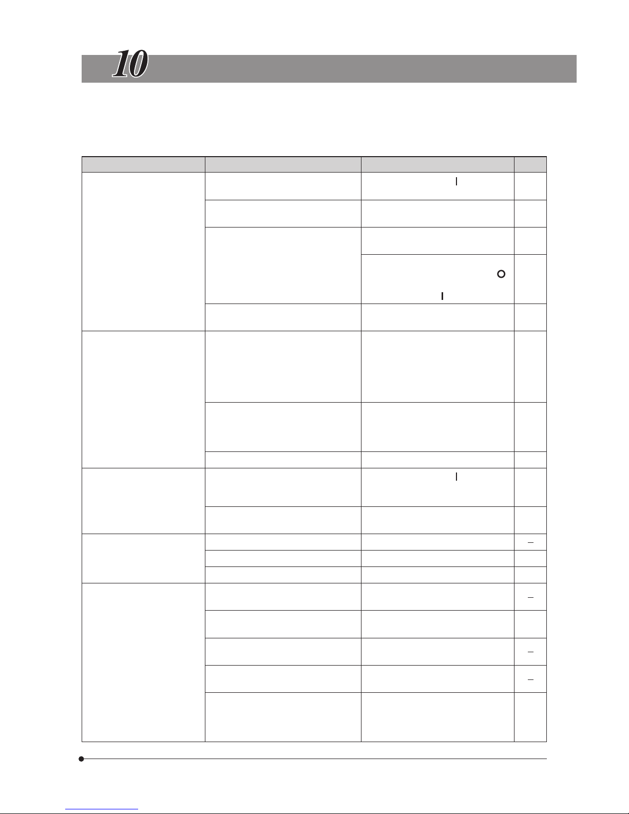
47
DP20
TROUBLESHOOTING GUIDE
Under certain conditions, the performance of the camera may be adversely affected by factors other than defects.
If problems occur, please review the following list and take remedial action as needed. If you cannot solve the
problem after checking the entire list, please contact Olympus for assistance.
Problem
Cause Remedy Pages
a) The control box buttons do
not work.
The main switch of the control box is not
ON.
Set the main switch to “ ” (ON).
The AC adapter is not connected properly. Connect it properly to the control box
and to the power outlet.
The PC is connected to the control box
through a USB 2.0 cable, setting the
camera system for PC control.
Operate the camera system from the
utility software running on the PC.
To operate the camera system from the
control box, set the main switch to “ ”
(OFF), unplug the USB 2.0 cable and set
the main switch to “ ” (ON) again.
The display resolution is inappropriate
and the picture is not displayed.
Set the display resolution properly.
b) Picture cannot be recorded
by pressing the EXPOSE
button.
Data is being written in the CF card. Release the EXPOSE button and wait
for more than 1 second before pressing
the EXPOSE button again.
If the memory gauge bar indicates the
full condition (4 bars), wait until the
indication becomes 0.
The CF card is full. Use another CF card, erase unwanted
pictures, or down load existing pictures
to the PC then erase all pictures in the
CF card.
The CF card is not inserted properly. Insert it completely.
c) Picture cannot be played on
the display screen.
The main switch of the control box is not
ON or the camera system is not in PLAY
mode.
Set the main switch to “ ” (ON).
Select PLAY mode.
No data has been recorded in the CF
card.
Check the number of remaining pictures.
d) The display shows nothing. The display is not ON. Turn the display ON.
The display resolution is inappropriate. Set the display resolution properly.
The display is set to the SLEEP mode. Set a proper sleep time.
e) The picture is not in focus. The microscope is not focused properly. Adjust the focus correctly with the fine
adjustment knob.
The confocality is adjusted improperly. Perform the confocal adjustment with the
TV adapter.
The aperture iris diaphragm of the
condenser is open too wide.
Close the aperture iris diaphragm a little.
The field iris diaphragm is not set properly. Adjust the field iris diaphragm until the
image circumscribes the field of view.
Lens components of the microscope are
contaminated or the cover glass on the
bottom of the camera head is stained.
Clean the objective, photography lens,
condenser and/or window lens of the
microscope, or clean the cover glass on
the bottom of the camera head.
13
9
36
36,38
26
16
30
11
29
29
19
12
3
26
Page 52
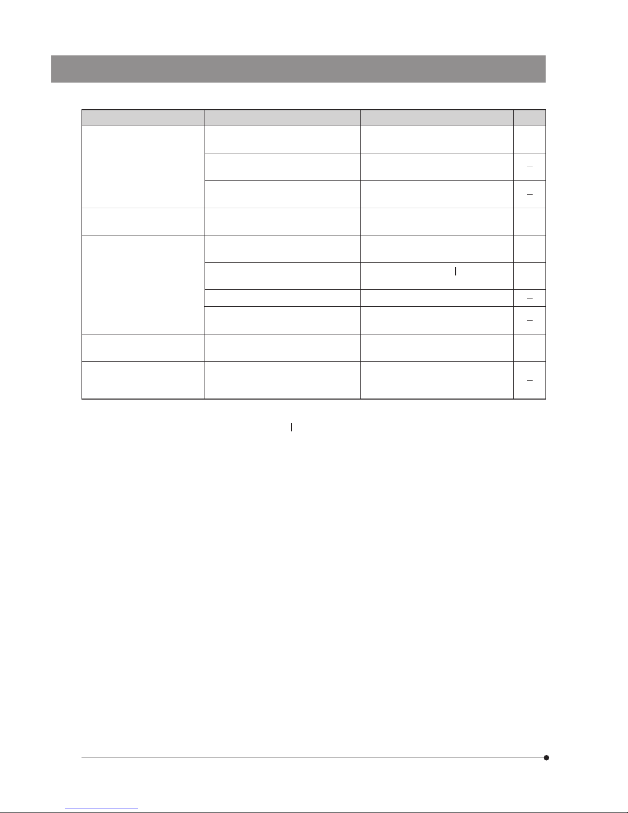
48
Problem Cause Remedy Pages
f ) Picture is too dark or bright. AE LOCK, exposure adjustment and/or
spot metering are not set properly.
Set them properly.
The illumination brightness is not set
properly.
Adjust the brightness.
A fluorescent lamp is in use. Use an illumination other than a
fluorescent lamp.
g) The colors in the picture are
strange.
A wrong color temperature is set in the
white balance control operation.
Set the color temperature properly.
h) Error message is displayed
during data downloading to
PC.
The USB 2.0 cable is not connected
properly.
Connect it properly.
The main switch of the control box is not
ON.
Set the main switch to “ ” (ON).
The PC is connected through a hub. Remove the hub.
i) Data downloading to PC
takes long time.
The connected PC is incompatible with
USB 2.0.
Use a USB 2.0-compatible PC.
}If no operation can be activated by pressing any of the buttons, unplug the AC adapter’s power cord from the power
outlet, plug it again and set the main switch to “ ” (ON) again.
13,14
19
36,38
13
35
An additional USB device is connected
to the PC.
Replace the USB port or remove the additional USB device from the PC.
j ) An additional USB device
cannot be used simultaneously.
Compatibility with the PC is poor. Replace the USB port or disconnect the
DP20 from the PC if an additional USB
device is used.
Page 53
49
DP20
PROPER SELECTION OF THE POWER SUPPLY CORD
If no power supply cord is provided, please select the proper power supply cord for the equipment by referring to “ Specifications ” and
“ Certified Cord ” below:
CAUTION:
In case you use a non-approved power supply cord for Olympus products, Olympus can no longer warrant the
electrical safety of the equipment.
Specifications
Voltage Rating
Current Rating
Temperature Rating
Length
Fittings Configuration
125V AC (for 100-120V AC area) or, 250V AC (for 220-240V AC area)
6A minimum
60°C minimum
3.05 m maximum
Grounding type attachment plug cap. Opposite terminates in molded-on IEC configuration appliance coupling.
Table 1 Certified Cord
A power supply cord should be certified by one of the agencies listed in Table 1 , or comprised of cordage marked with an
agency marking per Table 1 or marked per Table 2. The fittings are to be marked with at least one of agencies listed in
Table 1. In case you are unable to buy locally in your country the power supply cord which is approved by one of the
agencies mentioned in Table 1, please use replacements approved by any other equivalent and authorized agencies in
your country.
Country Agency
Certification
Mark
Country Agency
Certification
Mark
Argentina
Australia
Austria
Belgium
Canada
Denmark
Finland
France
Germany
Ireland
IRAM
SAA
ÖVE
CEBEC
CSA
DEMKO
FEI
UTE
VDE
NSAI
Italy
Japan
Netherlands
Norway
Spain
Sweden
Switzerland
United
Kingdom
U.S.A.
IMQ
ASTA
BSI
UL
KEMA
NEMKO
AEE
SEMKO
SEV
JET, JQA, TÜV,
UL-APEX / MITI
Page 54
50
Table 2 HAR Flexible Cord
APPROVAL ORGANIZATIONS AND CORDAGE HARMONIZATION MARKING METHODS
Approval Organization
Printed or Embossed Harmonization Marking (May be located on
jacket or insulation of internal wiring)
Alternative Marking Utilizing
Black-Red-Yellow Thread (Length
of color section in mm)
Black Red Yellow
Comite Electrotechnique Belge
(CEBEC)
Verband Deutscher Elektrotechniker
(VDE) e.V. Prüfstelle
Union Technique de l´Electricite´
(UTE)
Instituto Italiano del Marchio di
Qualita´ (IMQ)
British Approvals Service for Electric
Cables (BASEC)
N.V. KEMA
SEMKO AB Svenska Elektriska
Materielkontrollanstalter
Österreichischer Verband für
Elektrotechnik (ÖVE)
Danmarks Elektriske Materialkontroll
(DEMKO)
National Standards Authority of Ireland
(NSAI)
Norges Elektriske Materiellkontroll
(NEMKO)
Asociacion Electrotecnica Y
Electronica Espanola (AEE)
Hellenic Organization for
Standardization (ELOT)
Instituto Portages da Qualidade
(IPQ)
Schweizerischer Elektro
Technischer Verein (SEV)
Elektriska Inspektoratet
CEBEC <HAR>
<VDE> <HAR>
USE <HAR>
IEMMEQU <HAR>
BASEC <HAR>
KEMA-KEUR <HAR>
SEMKO <HAR>
<ÖVE> <HAR>
<DEMKO> <HAR>
<NSAI> <HAR>
NEMKO <HAR>
<UNED> <HAR>
ELOT <HAR>
np <HAR>
SEV <HAR>
SETI <HAR>
10 30 10
30 10 10
30 10 30
10 30 50
10 10 3 0
10 30 30
10 10 5 0
30 10 50
30 10 30
30 30 50
10 10 7 0
30 10 70
30 30 70
10 10 9 0
10 30 90
10 30 90
Underwriters Laboratories Inc. (UL) SV, SVT, SJ or SJT, 3 X 18AWG
Canadian Standards Association (CSA) SV, SVT, SJ or SJT, 3 X 18AWG
Page 55

Page 56

Shinjuku Monolith, 3-1, Nishi Shinjuku 2-chome, Shinjuku-ku, Tokyo, Japan
Postfach 10 49 08, 20034, Hamburg, Germany
2 Corporate Center Drive, Melville, NY 11747-3157, U.S.A.
One Corporate Drive, Orangeburg, NY 10962, U.S.A.
491B River Valley Road, #12-01/04 Valley Point Office Tower, Singapore 248373
2-8 Honduras Street, London EC1Y OTX, United Kingdom.
31 Gilby Road, Mt. Waverley, VIC 3149, Melbourne, Australia.
6100
Blue Lagoon Drive, Suite 390 Miami, FL 33126-2087, U.S.A.
Printed in Japan 2006 04 M 010–²
This publication is printed on recycled paper.
 Loading...