

Olympus DELTA 50, DELTA Premium, DELTA Professional, DELTA Classic Plus, DELTA Element Quick Start Manual
Page 1

DELTA Family
Handheld XRF Analyzer
Quick Start Guide
Models:
DELTA 50
DELTA Premium
DELTA Professional
DELTA Classic Plus
DELTA Element
International edition
103076-01EN [U8998318] — Rev. C
June 2014
This instruction manual contains essential information on how to use this Olympus product safely and effectively. Before using
this product, thoroughly review this instruction manual. Use the product as instructed.
Keep this instruction manual in a safe, accessible location.
Page 2
103076-01EN [U8998318], Rev. C, June 2014
IMPORTANT
CONTENTS
Unpacking the Instrument and Docking Station................................................................................................................Page 2
Instrument Overview................................................................................................................................................................Page 4
Safety Information ....................................................................................................................................................................Page 8
Instrument Batteries................................................................................................................................................................Page 10
User Interface ...........................................................................................................................................................................Page 13
Operation ..................................................................................................................................................................................Page 15
DELTA Radiation Profile .......................................................................................................................................................Page 19
Important Information — Please Read Before Use ...........................................................................................................Page 25
• Read the Important Information section carefully before handling this product.
• Refer to the DELTA User’s Manual (P/N: 103201-01EN) for more detailed information.
1. Unpacking the Instrument and Docking Station
This Quick Start Guide applies to the following models of DELTA handheld XRF analyzers:
•DELTAPremium
• DELTA 50 Premium
• DELTA Professional
• DELTA 50 Professional
• DELTA Classic Plus
•DELTAInspector
• DELTA Element
To unpack the instrument
1. Locate and remove the shipping papers and documentation.
2. Open the carrying case, and then remove the DELTA and all of the components.
Please note that there are two layers of protective foam padding.
3. Make sure the top layer of the foam is clear of any items, then lift it to expose the docking station and optional AC
power adaptor.
4. Inspect all components for damage and report any problems to Olympus immediately.
2 Unpacking the Instrument and Docking Station
Page 3
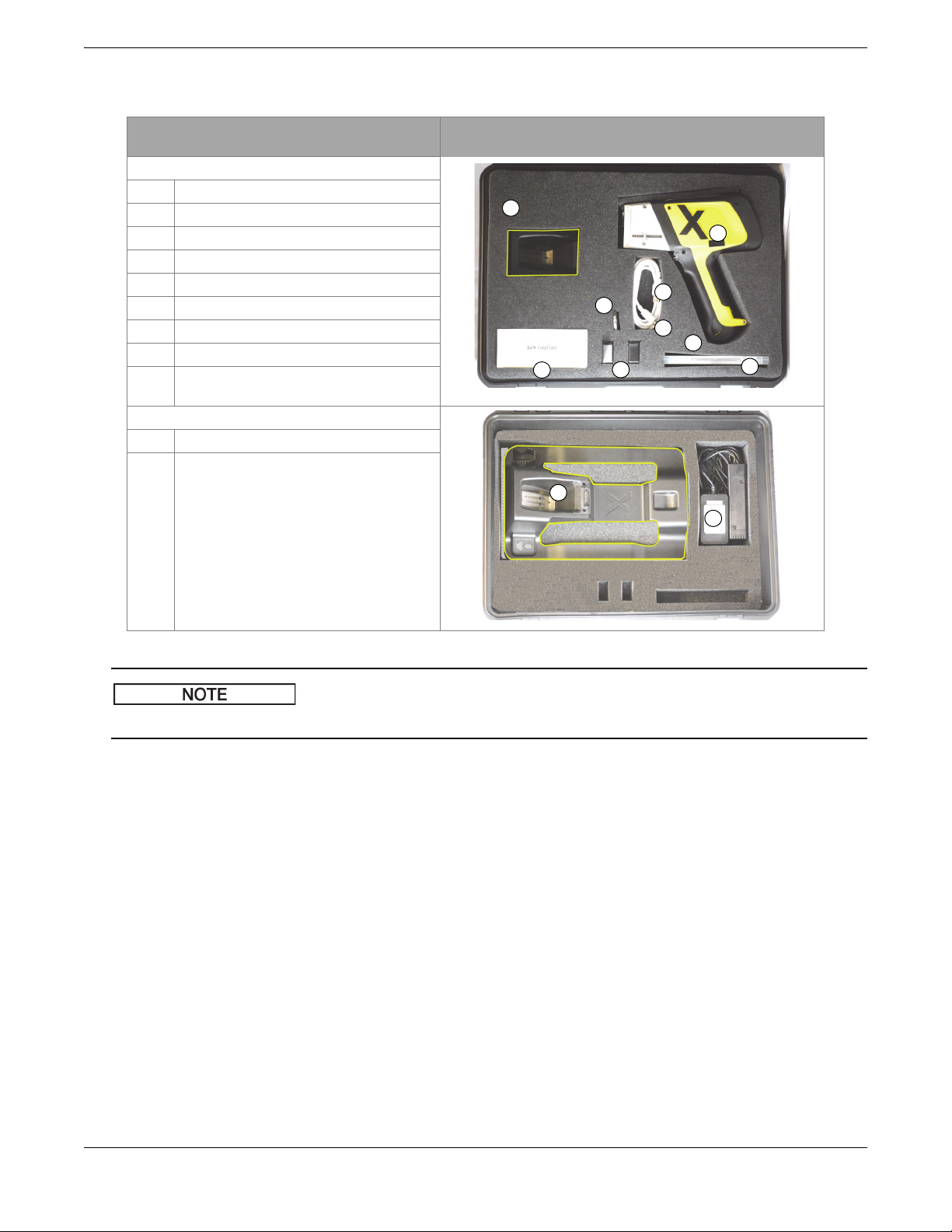
Item checklist for DELTA handheld XRF analyzer
1
2
3
4
5
6
7
8
9
11
10
NOTE
Component Key DELTA — All models except DELTA Element and DELTA
Foam: top layer
1 Carry case
2DELTA analyzer
3 Docking station charger
4 USB cable 1 (see page 6 for details)
5 USB cable 2 (see page 6 for details)
6 Li-ion batteries (2)
7 Calibration check (Cal Check) coupon
8 Extra windows (bag of 10)
9 End user documentation (not shown)
Foam: second layer
10 Docking station
11 AC power adaptor (optional)
103076-01EN [U8998318], Rev. C, June 2014
Inspector
For the DELTA Element and DELTA Inspector, the docking station is replaced by the battery charger.
Unpacking the Instrument and Docking Station 3
Page 4
103076-01EN [U8998318], Rev. C, June 2014
1
2
3
4
5
6
7
8
9
11
12
10
13
14
2. Instrument Overview
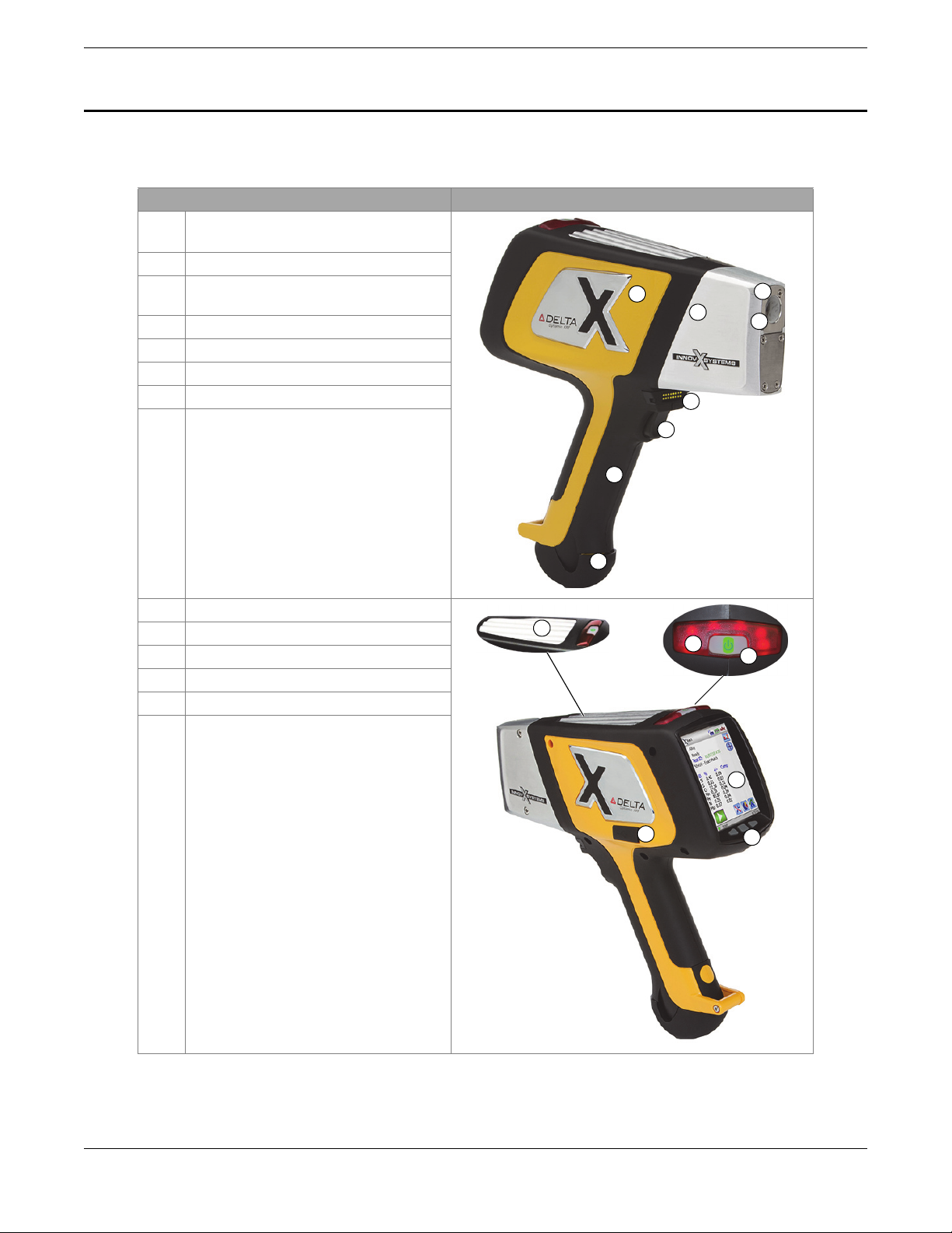
2.1 Handheld Analyzer
Component Key DELTA — All models
1 DELTA analyzer (Premium model
shown)
2Probe
3 Measurement window (Prolene or
Kapton film)
4 Hinged window plate
5 Docking station connector
6Trigger
7 Handle — Non-slip rubber grip
8 Battery boot
9 Data port with rubber cover
10 Heat sink
11 I/O (power) switch with LED indicator
12 X-ray warning light array
13 User interface touch screen
14 Navigation keys
4 Instrument Overview
Page 5
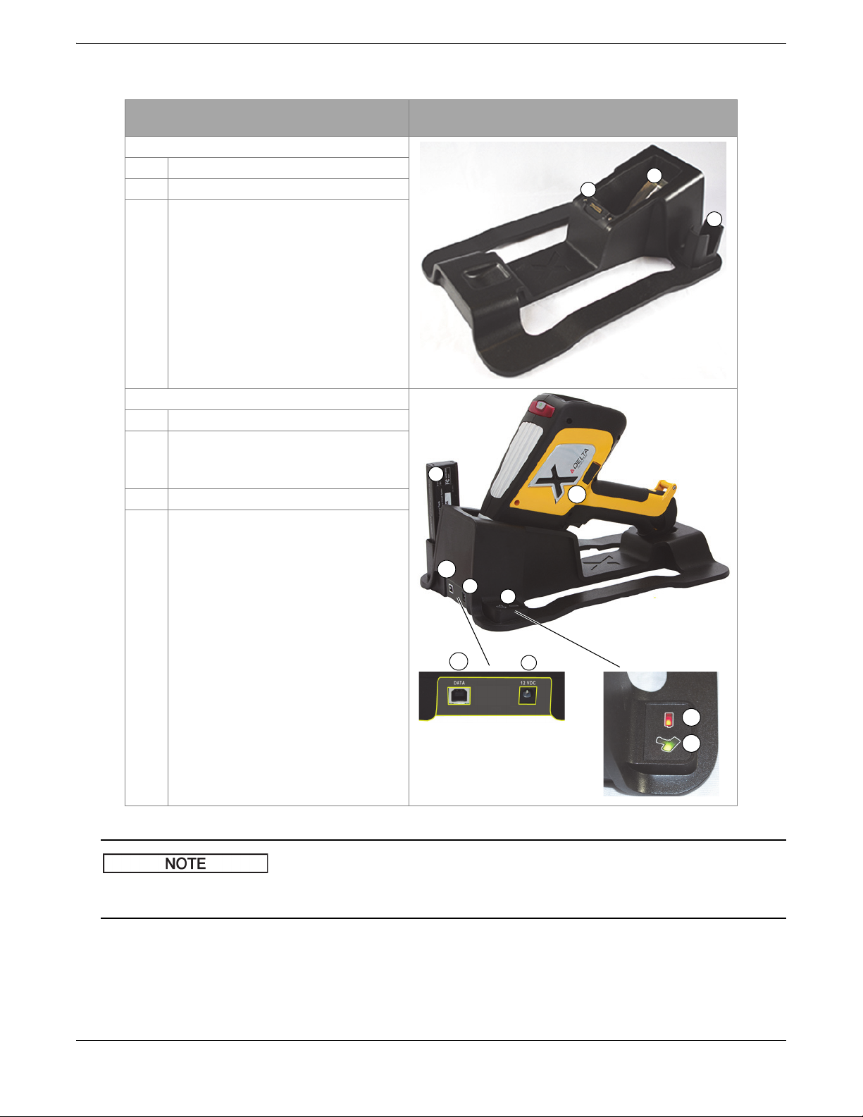
2.2 Docking Station
1
2
3
5
7
8
6a
7
8a
8b
6a
6b
Component Key DELTA — All models except DELTA Element and
Docking station (empty)
1 Analyzer signal/control connector
2 Second battery charger socket
3 Cal Check test cup (316 stainless steel)
Docking station (loaded)
5 Second battery in socket
6 Data port(s):
a) Docking station (rear)
b) Analyzer (left side)
7Input power (12VDC)
8 Indicator lights:
a) Second battery charging
b) Analyzer engaged
103076-01EN [U8998318], Rev. C, June 2014
DELTA inspector
The DELTA docking station is a standard accessory for all DELTA models except the DELTA Element and the DELTA
Inspector series.
2.3 Battery Charger
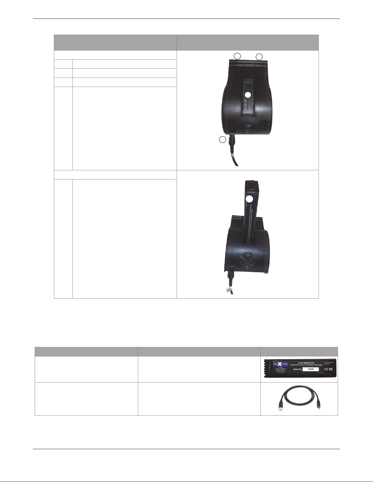
The battery charger (U8990854) with an AC input and a single Li-ion battery socket comes standard with DELTA Element
and DELTA Inspector models. This battery charger is described in section 4.2.2 on page 11.
Instrument Overview 5
Page 6
103076-01EN [U8998318], Rev. C, June 2014
1
2
4
3
5
Component key DELTA — All models (standard on the DELTA Element
Battery charger (empty)
1Input power (12VDC)
2 Battery cradle and connectors
3 Charging error indicator
4 Battery charging/charged indicator
Battery charger (loaded)
5 Battery in cradle
and DELTA Inspector)
2.4 Components and Accessories
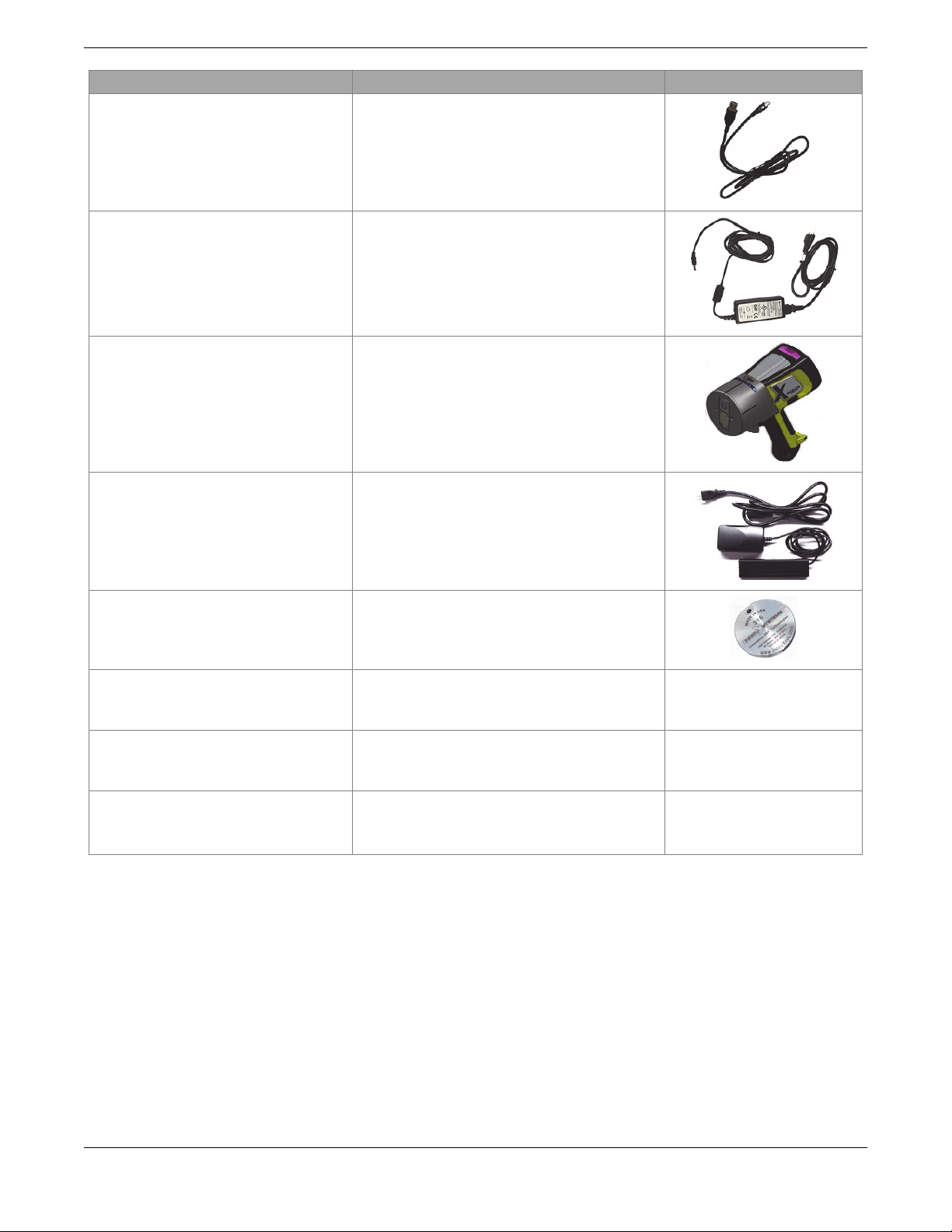
The items included with the DELTA analyzer and docking station are shown below. Unless otherwise noted, all parts are
standard accessories.
Item Description
Li-ion batteries High capacity, 4.8 Ah to 5.2 Ah; comes with two
USB cable 1 Six feet in length, 480 Mbps, USB A to USB B
6 Instrument Overview
batteries.
connectors.
Page 7
103076-01EN [U8998318], Rev. C, June 2014
Item Description
USB cable 2 Mini USB B to USB A connectors.
AC power adaptor Provides DC power to docking station.
Input: 110–240 VAC; Output: 60 W, 12 VDC, 5 A.
DELTA 50 probe shield Provides maximum shielding, recommended for
extended handheld use of the DELTA 50.
NOTE: The probe shield is included as a
standard accessory with DELTA 50 analyzers.
AC power adaptor Li-ion battery replacement; 110– 240 VAC power
source. This unit is an optional accessory.
Cal Check coupon N/A
Prolene Windows — Premium, Premium
Plus, Standard and Professional models
Kapton Windows — Classic,
Classic Plus, Inspector, Element models
DELTA Documentation Suite —User’s Manual (P/N: 103201-01EN)
Bag with 10 pieces of 6 μm film windows. N/A
Bag with 10 pieces of 6 μm film windows. N/A
N/A
—User Interface Guide (P/N: 103202-01EN)
—Safety and Informational Package
2.5 Packing and Shipping
If the DELTA handheld XRF analyzer is not returned in its transport case, it could be damaged during shipping. Olympus
reserves the right to void the warranty on instruments damaged while in transit if they are shipped without their transport
case. Prior to returning any units, contact Customer Service to obtain the required RMA number(s) and any important
shipping information
To return your XRF analyzer
1. Pack the analyzer back into the transport case that it came in using the original packing materials.
2. Include the RMA in the case, and reference the RMA number in your shipping documents.
3. Close the transport case and either:
• Secure it with plastic zip ties, or;
• Pack the transport case within another box.
Instrument Overview 7
Page 8
103076-01EN [U8998318], Rev. C, June 2014
When shipping the Li-ion battery, be sure to follow all local transportation regulations.
3. Safety Information
3.1 Radiation Safety Information
Olympus handheld XRF analyzers are secure and dependable instruments when used in accordance with recommended
testing techniques and safety procedures.
• Olympus analyzers must only be used by trained and authorized operators in accordance with proper safety
procedures. Improper use may impair safety protection and cause potential harm to the user.
• Read all warning signs and labels.
• DO NOT USE the instrument if there is any evidence of damage, as doing so could cause unintentional emission of
stray radiation. In such a case, arrange for qualified personnel to perform a radiation safety test and repair any
damage to the instrument.
3.2 Safety Interlock Structure
To control X-ray emissions, thereby minimizing the possibility of accidental exposure, the DELTA handheld XRF analyzer
has a standard safety interlock structure consisting of the three features listed below:
1. Software proximity sensor
Within one second of a test start, the analyzer detects the sample in front of the measurement window. If no sample is
detected the test aborts to prevent accidental exposure, the filter wheel goes to position 0, and the X-rays shut off. The
tube current is reduced to 0.0 μA, and the red light stops blinking. Also, if the probe/nose is pulled away from the
sample while a test is in progress, testing stops in approximately one second.
2. Software trigger lock
If five minutes elapse between tests (default time), the trigger automatically locks and you must tap on the Lock button
( ) to unlock it.
3. Safeguards
As an owner of an Olympus handheld XRF analyzer, your safeguards include those items indicated below:
• Limited access
Keep the instrument in a controlled location to which only trained and authorized users have access.
• Trained operators
Post a sign near the analyzer indicating that it must only be used by operators who have completed a training
class provided by your company, or who have attended an Olympus training course and completed any other
requirements stipulated by the local regulating authority. When the Olympus instrument is turned on, the user
interface screen displays a message indicating that the instrument should only be used by authorized personnel.
•Shielding issues
An Olympus handheld XRF analyzer emits a tightly collimated beam of X-ray radiation. Although attenuation
occurs, the beam may project many meters in open air.
Adequate shielding is achieved by:
— Establishing a no-admittance zone sufficiently distant from the instrument’s measurement window to allow
air to attenuate the beam.
8 Safety Information
Page 9
103076-01EN [U8998318], Rev. C, June 2014
Power switch
X-ray indicator
— Enclosing the beam working area with protective panels (for example, 3.0 mm stainless steel can attenuate
the beam to background levels)
Contact your Olympus representative for assistance and suggestions on interlocks and applications that limit
radiation exposure.
• Trigger issues
“Deadman trigger” mode requires the user to pull and hold down the trigger for the duration of the test.
Releasing the trigger immediately aborts the test.
3.3 Indicators and Statuses
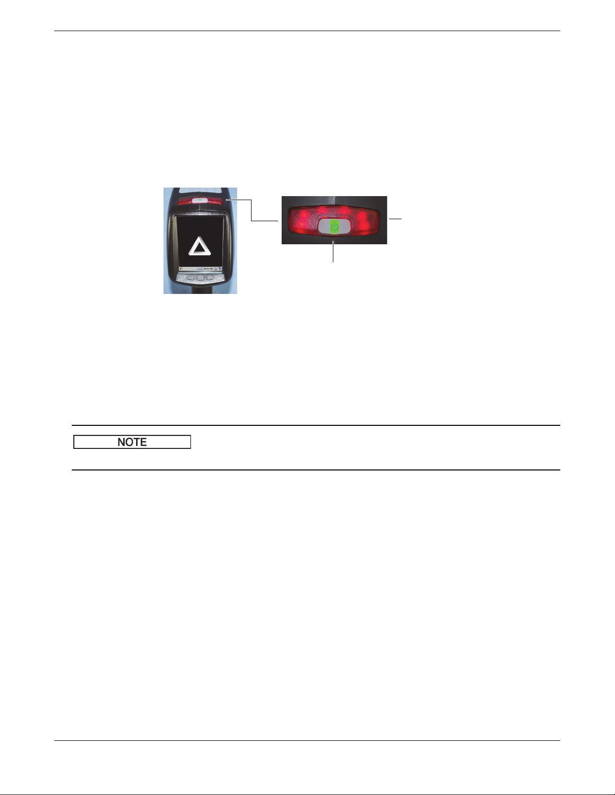
This section explains the DELTA handheld XRF analyzer’s indicators (see Figure 3-1 on page 9) and statuses.
Figure 3-1 Power switch and X-ray indicators
3.3.1 Power Switch with Integral Indicator Light
The power switch is located at the upper rear of the analyzer (see Figure 3-1 on page 9).
POWER ON
Press the I/O switch to turn on the power.
A green LED indicator illuminates.
This switch DOES NOT turn the X-ray tube on. No tube power is supplied until the Olympus software is launched.
POWER OFF
Press and hold switch for more than three seconds.
The instrument powers off (see section “Exit Options” on page 17 for more exit options).
3.3.2 X-Ray Indicator
The X-ray indicator is located on the upper rear of the instrument (see Figure 3-1 on page 9). It consists of a six-element red
LED array and provides two key functions:
X-ray indicator continuously ON (solid red LED array)
This signifies that:
•The X-ray tube is enabled.
• There is no radiation exposure to you or bystanders.
The instrument can be carried or set down safely in this condition.
X-ray indicator flashing ON (blinking red LED array)
This signifies that:
• The X-ray tube is powered to full operational level.
• The analyzer is emitting X-ray radiation through the measurement window.
In this condition, the analyzer must be pointed towards a test sample.
Safety Information 9
Page 10
103076-01EN [U8998318], Rev. C, June 2014
Status bar
3.3.3 Test Screen
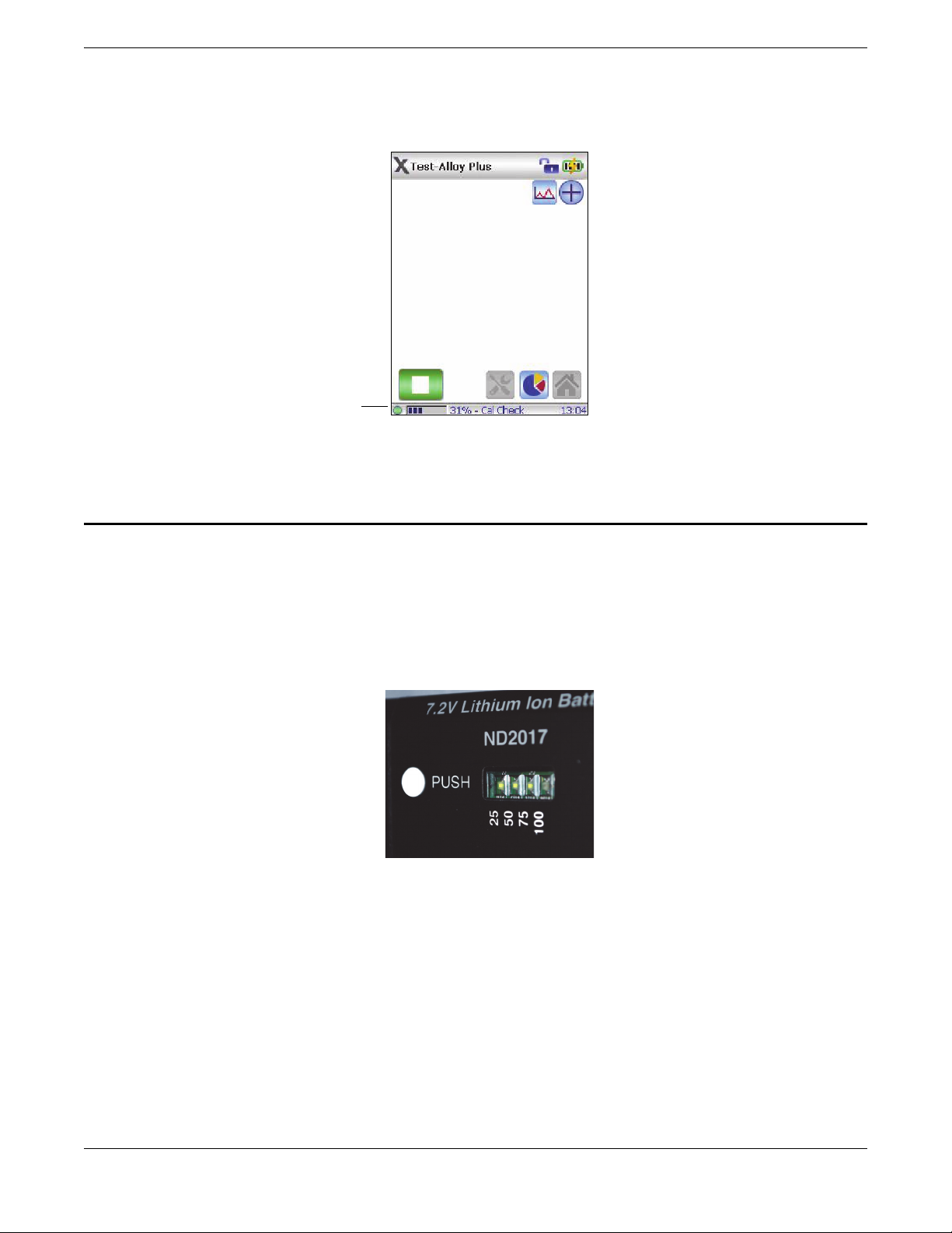
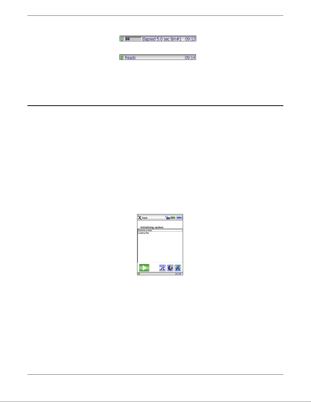
During Cal Checks or while samples are being tested, the test screen’s lower status bar provides an indication of the
progress (see Figure 3-2 on page 10). Upon completion, a Ready indicator is displayed (ready for next operation).
Figure 3-2 Test screen status bar
4. Instrument Batteries
This section explains how to use and charge the batteries of a DELTA handheld XRF analyzer.
4.1 Battery Status
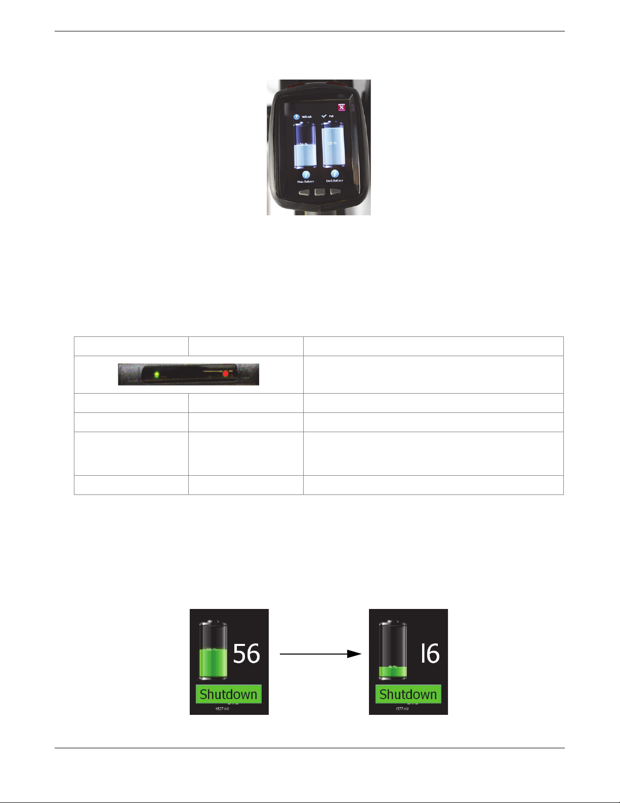
To test a Li-ion battery charge status, press the white button on the battery (see Figure 4-1 on page 10). The green lights
indicate the percent of charge remaining, ranging from less than 25 % to 100 %. If a battery has a charge of less than 25 %,
use the docking station to perform a full charge.
Figure 4-1 Battery charge status button
4.2 Charging Batteries
4.2.1 Charging Batteries Using the Docking Station
The DELTA handheld XRF analyzer comes with a new multipurpose tool: a docking station (see section “Docking Station”
on page 5 for hardware details). In addition to providing an automatic Cal Check, the docking station delivers two
charging functions:
• It can be used to charge the installed Li-ion battery located in the instrument’s handle.
• Simultaneously, it can be used to charge a second battery with its special battery charging socket.
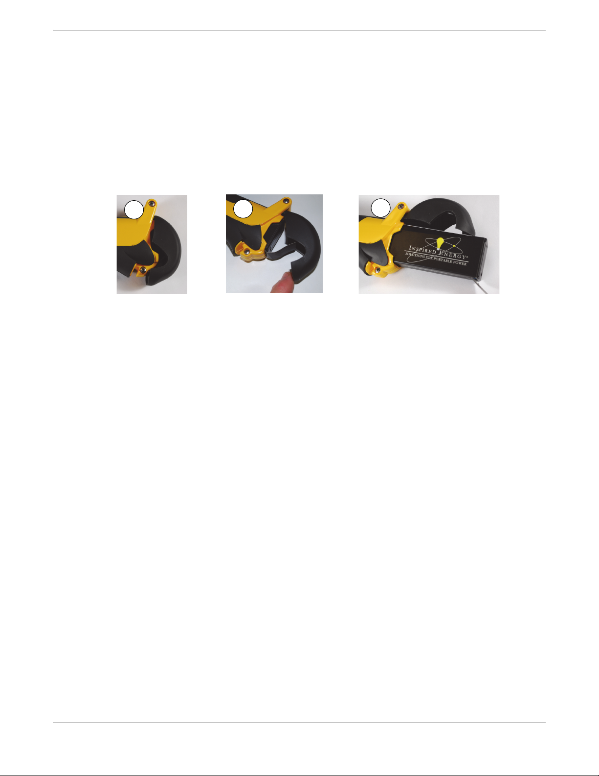
The charge status is shown in real-time on the DELTA’s display screen (see Figure 4-2 on page 11).
10 Instrument Batteries
Page 11
103076-01EN [U8998318], Rev. C, June 2014
The status of the second docked battery (either charging = red or full = green) is also shown on the battery indicator located
on the left rear side of the docking station.
Figure 4-2 Battery charge status
4.2.2 Charging Batteries Using the Battery Charger
The battery charger is a standard accessory with the DELTA Element and DELTA Inspector models. It is an optional
accessory for all other models.
The charger takes about two hours to completely charge a battery. The battery charge status is indicated by two lights on
the power adaptor.
Left light (green only) Right light (red only) Status
On — Flashing Off The battery is charging.
On — Solid Off The battery is charged.
Off On — Solid Error. Remove the battery, and then place it back on the
charger. If the error persists, call Olympus Technical Support.
Off Off There is no battery on the charger.
4.3 Hot Swap for a DELTA Battery
A battery hot-swap capability is a standard feature with the DELTA handheld XRF analyzer. You can remove and replace a
battery without having to shut down, restart, or perform a Cal Check.
A “shutdown” status display gives the percentage of internal charge remaining when the battery is removed (see
Figure 4-3 on page 11). If the internal charge reaches 0, insert a new battery and then, restart the analyzer with the I/O
switch. If the red X-ray indicator lights are flashing, the battery voltage is too low.
Figure 4-3 Shutdown status
Instrument Batteries 11
Page 12
103076-01EN [U8998318], Rev. C, June 2014
1
2
3
4.4 Replacing the Battery
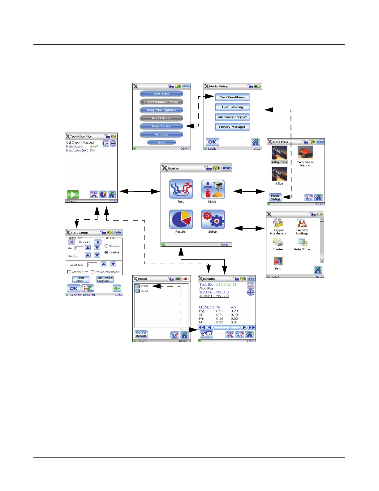
Perform the following procedure to replace the battery of the DELTA handheld XRF analyzer. See also Figure 4-4 on
page 12.
To replace the battery
1. Hold the analyzer upside down by the handle, with the bottom of the analyzer base pointing upward, and the nose
pointing away from the operator.
2. Pull the rubber latch and lift the cover.
3. Pull the tab to remove the existing battery.
4. Insert the charged battery into the analyzer with the battery connectors facing to the left. The battery slot is keyed so
that the battery can only be inserted one way.
Figure 4-4 Battery replacement
12 Instrument Batteries
Page 13
103076-01EN [U8998318], Rev. C, June 2014
Mode
Setup
Te st
Results
Mode Setup
Results
Summary
Test Conditions
5. User Interface
The DELTA handheld XRF analyzer’s user interface opens with the startup radiation safety and initialization screens (see
chapter “Operation” on page 15). The main operations are accessible from the Home screen (see Figure 5-1 on page 13).
Refer to the User Interface Guide (P/N: 103202-01EN) for complete software details.
Figure 5-1 DELTA user interface
User Interface 13
Page 14
103076-01EN [U8998318], Rev. C, June 2014
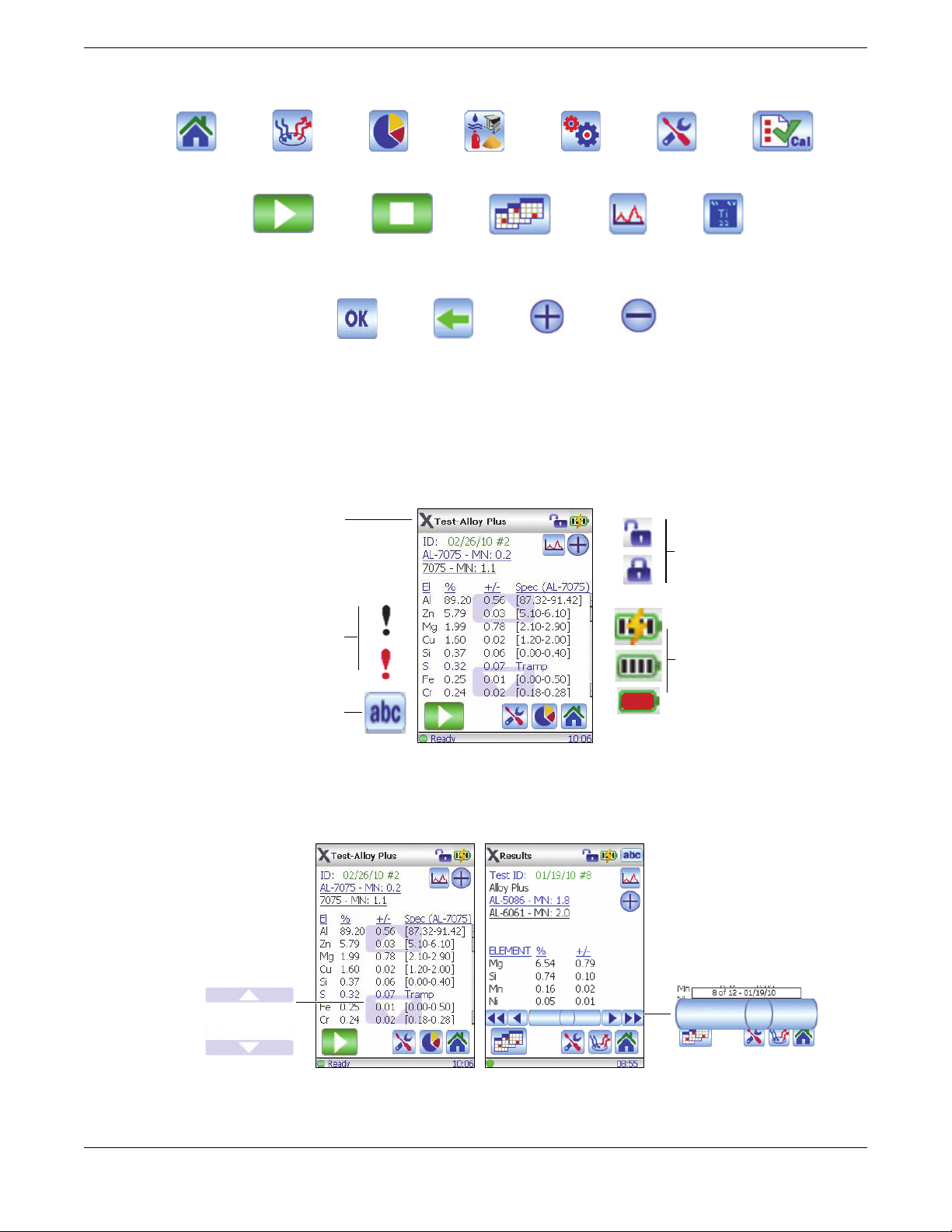
Home Test Results Mode Setup Tools Cal Check
Start Test Stop Test Results:
Navigation
Display:
Spectrum
Display:
Chemistry
Exit screen and
save changes
Exit screen and
don’t save
changes
Display:
Expand
Display:
Minimize
X = Review S/W
Title: Name of screen and current
mode
Padlock trigger indicators
Battery status indicators
Information indicators:
Black = Messages
Red = Errors
Display: Keyboard
On-screen vertical
scrolling: Use your finger
to move the display
vertically for added
information.
On-screen horizontal
scrolling: Use your finger
to move the display
horizontally for added
information.
5.1 Buttons
5.2 Indicators
Figure 5-2 Buttons
Figure 5-3 User interface indicators
5.3 Horizontal and Vertical Scrolling
14 User Interface
Figure 5-4 Scrolling tools
Page 15
5.4 Lower Status Bar
Progress bar and text message
System OK/ready System time
Figure 5-5 Lower status bar
6. Operation
This chapter describes a typical operational sequence for the DELTA handheld XRF analyzer.
6.1 Typical Operating Procedure
To use the instrument
1. Insert a charged battery into the analyzer handle.
2. Turn on the analyzer using the I/O switch.
3. Read the radiation safety notice (see ), and then confirm that you are a certified user.
System initialization begins immediately.
The analyzer launches a test screen using the last selected mode (see Figure 6-1 on page 15).
4. If the mode is to be changed:
a) Go to the Home screen.
b) Select the Mode button.
c) Choose the desired mode.
103076-01EN [U8998318], Rev. C, June 2014
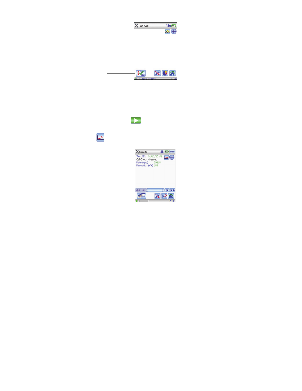
5. When the “Cal Check Required” message is displayed, place the analyzer in the docking station.
6. Navigate to the Te st S e t up screen, and then tap the Cal Check button (see Figure 6-2 on page 16).
Figure 6-1 Test screen
Operation 15
Page 16
103076-01EN [U8998318], Rev. C, June 2014
Cal Check button
Figure 6-2 Cal Check Required message
7. Tap the Start Test button.
The Cal Check takes approximately 15 seconds. After a successful Cal Check, the analyzer is ready for use.
8. Position the measurement window over the test sample.
9. Pull the trigger or tap the Start Test button ( ).
Results are displayed immediately upon test completion.
10. Tap the Spectrum button ( ) to view special results (see Figure 6-3 on page 16).
Figure 6-3 Results
11. At the end of the session, export the results to a PC using the data port and USB cable.
12. When testing and exporting are complete, turn off the analyzer using the I/O switch, or insert it into the docking
station.
6.2 About Calibration Check (Cal Check)
DELTA analyzers use advanced techniques for Cal Checking.
• The docking station (with its special 316 s/s test cup) provides an automatic Cal Check. The analyzer must be ON
when inserted.
• When in the field (and away from the docking station) you can use the 316 s/s standardization coupon to perform a
Cal Check. This check only takes 15 seconds.
16 Operation
Page 17
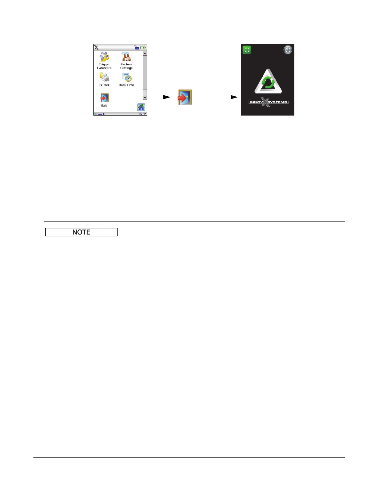
6.3 Exit Options
Setup screen
Exit
Confirm
The user has 3 options (see
below)
The user has three options:
1. Soft reboot
Restart operating system (OS) and the application.
2. Power OFF
Turn the analyzer off after confirmation.
3. Relaunch
Restart the application.
103076-01EN [U8998318], Rev. C, June 2014
Figure 6-4 Exit options
All user interface (UI) screens have a time-out (power-saving) feature that causes the screen to go blank if the UI is not
accessed or if the instrument is not moved within a 90-second interval. However, when this mode is enabled, the analyzer
is still running. To restore the screen, tap it or move the instrument.
Operation 17
Page 18

103076-01EN [U8998318], Rev. C, June 2014
18 Operation
Page 19
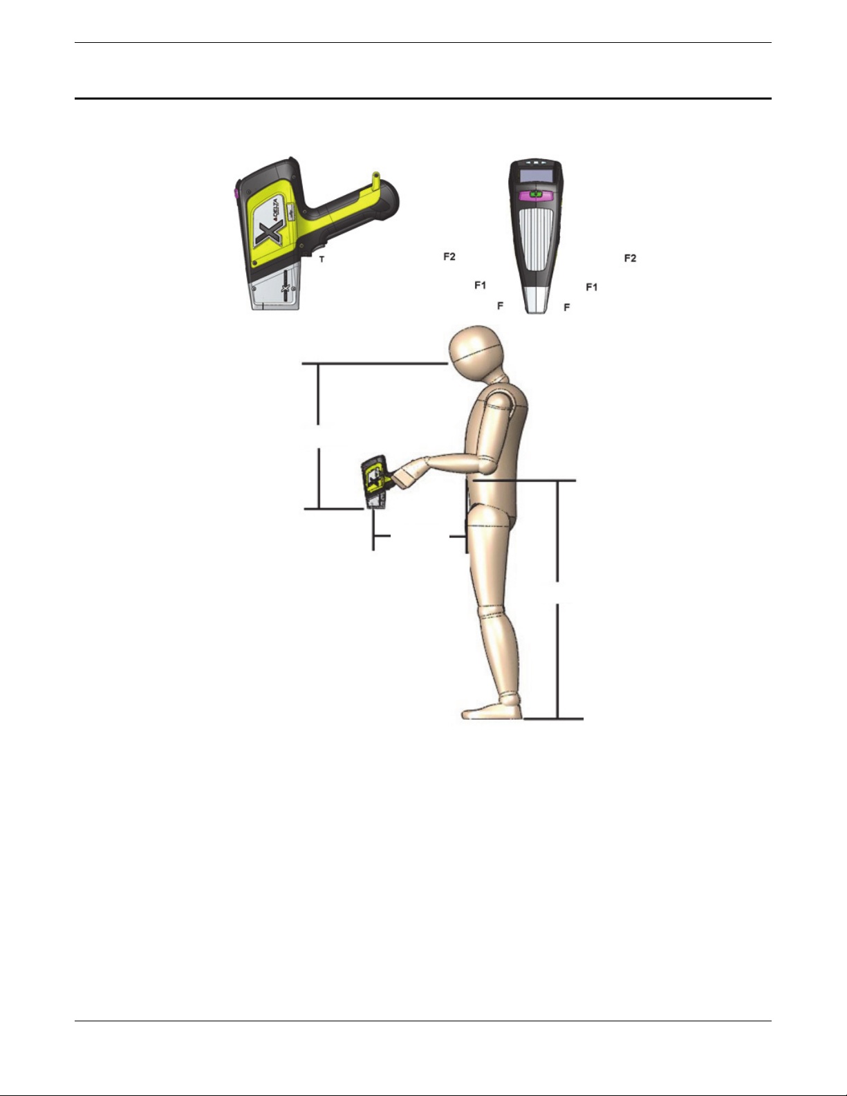
7. DELTA Radiation Profile
61 cm (24 in.)
102 cm (40 in.)
36 cm
(14 in.)
This chapter includes the radiation profiles for the DELTA handheld XRF analyzers.
103076-01EN [U8998318], Rev. C, June 2014
Figure 7-1 DELTA radiation profile — Handheld instruments
DELTA Radiation Profile 19
Page 20
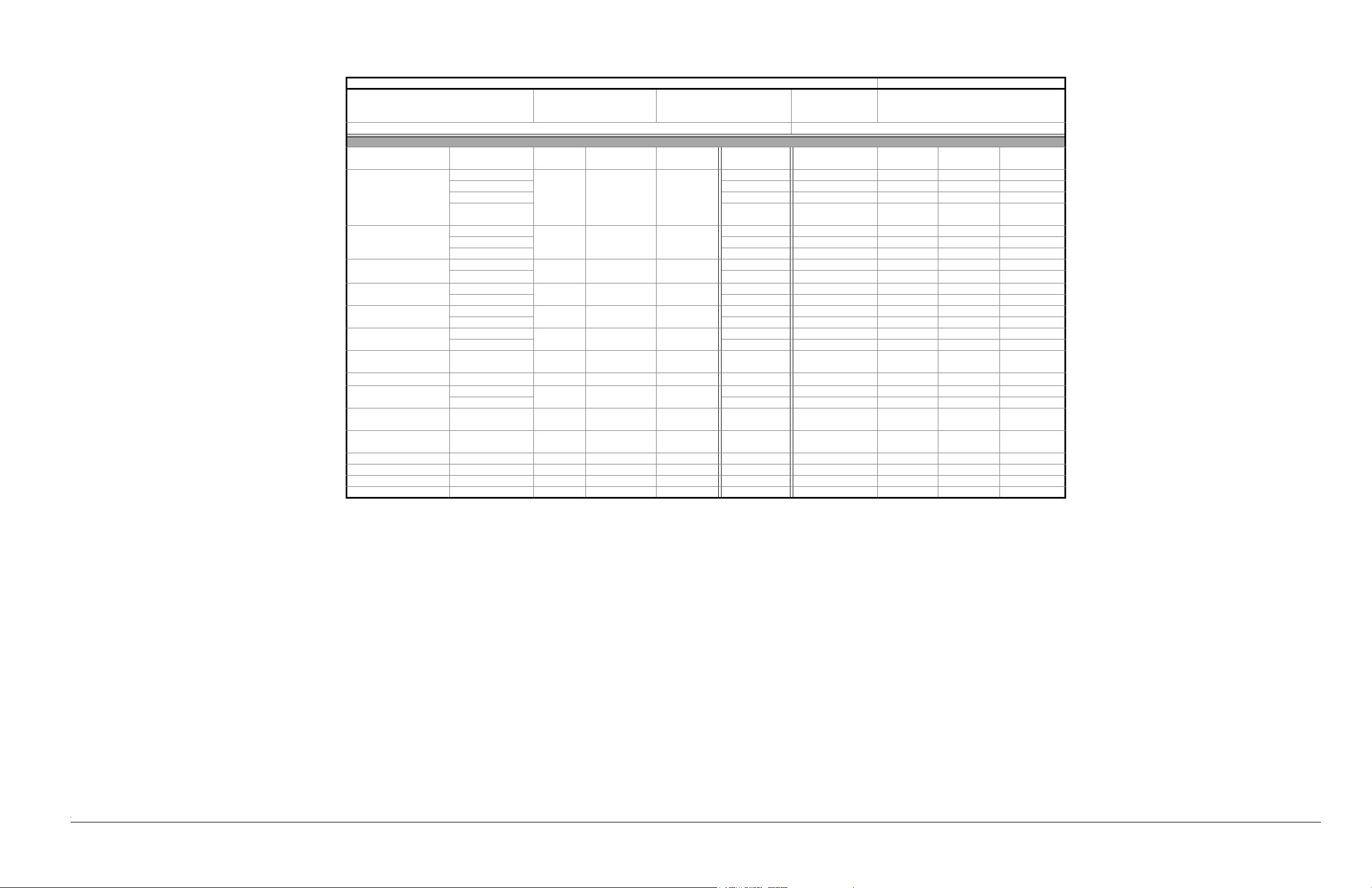
7
Table 1 Radiation profilea — Aluminum probe headb
Survey instrument Ludlum Model 3
44-7 probe
Ludlum Model 2241
44-172 probe
Performed by:
F. Cook
R. Nasella
Probe head: Aluminum
Measured dose rate in µSv/hc — Secondary radiation (scatter)
Model: DELTA Series Date: Oct. 2012 and Jan. 2013
Mode(s) Substrate Voltage
Alloy Plus, Mining,
Mining Plus,
GeoChem 1, 3-Beam
Soil 2, HalFree 1, RoHS 1
(plastic)
RoHS 1, 4-Beam RoHS 1
(plastic), RoHS 2,
4-Beam RoHS 2 (alloy)
316 stainless 40 100 Aluminum
Al (319 AA) 7 300 120 30 4
EC 680K 45 900 500 320 19
Soil (SiO
) 20 400 250 70 9
2
PVC-Blank
EC 680K 16 1800 800 500 30
71X SR2 (solder) BK 5 1 BK BK
(kV)
50
e
Amperage
(µA)
Filter Trigger — T Close — F 5 cm — F1 10 cm—F2 30 cm
BK
d
7 6 BK BK
80 Copper 10 840 400 250 15
Alloy, Mining 316 stainless 35 100 Aluminum BK 2 2 BK BK
Soil (SiO
) 5 130 60 20
2
Alloy Plus 3 316 stainless 8 200 Open BK BK BK BK BK
Al (319 AA) BK BK BK BK BK
Alloy Plus 2 316 stainless 13 200 Open BK BK BK BK BK
Al (319 AA) BK BK BK BK BK
Alloy 2 316 stainless 15 200 Iron BK BK BK BK BK
3-Beam Soil 1, Mining
Al (319 AA) BK BK BK BK BK
Soil (SiO
)
2
e
50
80 Copper 25 1500 800 450 30
Plus
3-Beam Soil 1 Soil (SiO
) 40 100 Copper 10 400 220 70 8
2
RoHS 2 (alloy) PVC-Blank 40 100 Copper 5 200 90 30 3
EC 680K 4 700 420 300 16
Geochem 2, Mining
Plus 2
3-Beam Soil 3 Soil (SiO
Soil (SiO
) 10 200 Open BK BK BK BK BK
2
) 15 200 Thin
2
BK BK BK BK BK
aluminum
Lead 2 71X SR2 (solder) 18 200 Aluminum BK BK BK BK BK
Lead 1 71X SR2 (solder) 25 100 Aluminum BK BK BK BK BK
HalFree 2 EC 680K 10 200 Open BK 8 1 BK BK
HalFree 2 EC 680K 12 200 Open BK 70 13 4 BK
a. Table revision D, January 2013.
b. Aluminum probe head only, no probe shield in place.
c. To convert measurements to mR/h, divide results by 10.
d. BK = Background reading (< 1 μSv/h).
e. All 50 kV readings are taken with standard probe shield in place.
Validated by: M. L. Tremblay
(calculated)
Page 21
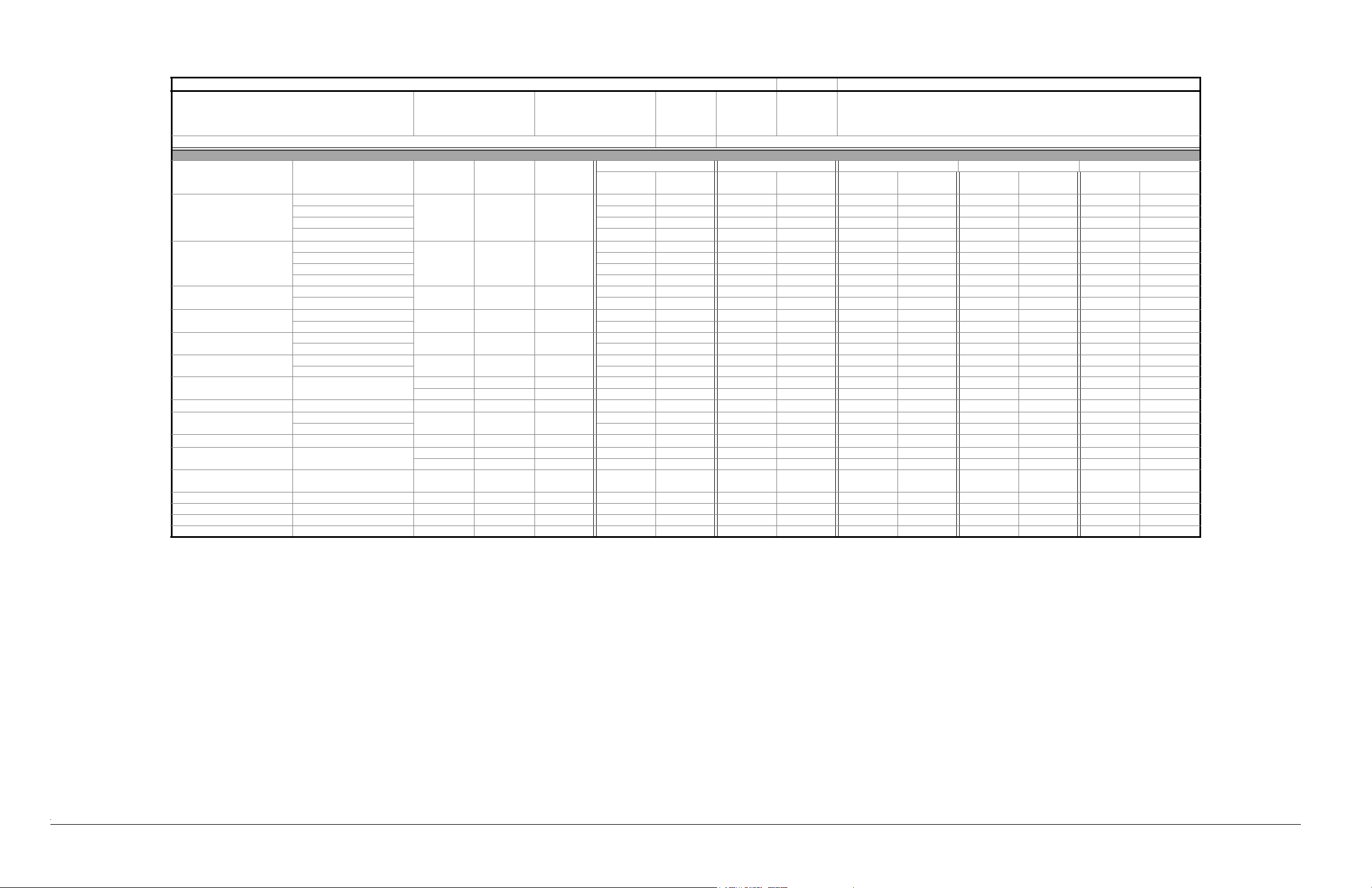
Table 2 Radiation profilea — Brass probe headb
Model: DELTA Series Date: Oct. 2012 and Jan. 2013
Survey instrument Ludlum Model 3
44-7 probe
Ludlum Model 2241
44-172 probe
Performed
by:
F. Cook
R. Nasella
Probe head: Brass alloy
Measured dose rate in µSv/hc — Secondary radiation (scatter)
Mode(s) Substrate Voltage (kV) Amperage
Alloy Plus, Mining, Mining
Plus, GeoChem 1, 3-Beam
Soil 2, HalFree 1, RoHS 1
(plastic)
RoHS 1, 4-Beam RoHS 1
(plastic), RoHS 2, 4-Beam
RoHS 2 (alloy)
(µA)
316 stainless 40 100 Aluminum
Al (319 AA) BK BK 5 BK BK BK BK BK BK BK
EC 680K 50 7 1500 950 700 370 400 160 26 14
Soil (SiO
) 20 4 850 300 500 280 200 110 19 10
2
PVC-Blank 50 80 Copper 25 5 650 400 600 200 120 60 22 7
EC 680K 60 9 1500 1000 1500 1000 750 200 56 37
71X SR2 (solder) BK BK BK BK BK BK BK BK BK BK
Filter Trigger — T Close — F 5 cm — F1 10 cm—F2 30 cm (calculated)
Probe head
only
BK
d
f
Probe shield
e
Probe head
Probe shield Probe head
only
BK BK BK BK BK BK BK BK BK
Al (319 AA) 1 BK 25 15 10 10 6 5 BK BK
Alloy, Mining 316 stainless 35 100 Aluminum BK BK BK BK BK BK BK BK BK BK
Soil (SiO
) BKBKBKBKBKBKBKBKBKBK
2
Alloy Plus3316 stainless 8 200OpenBKBKBKBKBKBKBKBKBKBK
Al (319 AA) BK BK 4 BK BK BK BK BK BK BK
Alloy Plus 2 316 stainless 13 200 Open BK BK BK BK BK BK BK BK BK BK
Al (319 AA) BK BK 4 BK BK BK BK BK BK BK
Alloy 2 316 stainless 15 200 Iron BK BK BK BK BK BK BK BK BK BK
Al (319 AA) BKBKBKBKBKBKBKBKBKBK
3-Beam Soil 1 Soil (SiO
3-Beam Soil 1 Soil (SiO
) 50 80 Copper 70 7 1000 500 750 350 300 50 28 13
2
) 40 100 Copper BK BK BK BK BK BK BK BK BK BK
2
50 # 60 # Copper 30 5 750 370 550 500 170 110 21 19
RoHS 2 (alloy) 316 stainless 40 100 Copper BK BK BK BK BK BK BK BK BK BK
Al (319 AA) BKBKBKBKBKBKBKBKBKBK
Geochem 2, Mining Plus 2 Soil (SiO
Mining Plus Soil (SiO
3-Beam Soil 3 Soil (SiO
) 10 200 Open BK BK BK BK BK BK BK BK BK BK
2
) 50 80 Copper 100 10 1750 750 750 350 300 28 13
2
)15200Thin
2
50 # 15 # Copper 15 4 300 170 160 100 80 40 6 4
BK BK BK BK BK BK BK BK BK BK
aluminum
Lead271X SR2 (solder) 18200AluminumBKBKBKBKBKBKBKBKBKBK
Lead171X SR2 (solder) 25100AluminumBKBKBKBKBKBKBKBKBKBK
HalFree 2 EC 680K 10 200 Open BK BK 3 BK 1 BK BK BK BK BK
HalFree 2 EC 680K 12 200 Open BK BK 3 BK 1 BK BK BK BK BK
a. Table revision D, January 2013.
b. Brass probe head for DELTA models sold in Japan, and 50 kV models sold in Canada.
c. To convert measurements to mR/h, divide results by 10.
d. Probe head only = No shield in place.
e. Probe shield = Standard probe shield in place.
f. BK = Background reading (< 1 μSv/h).
Validated by: M. L. Tremblay
Probe shield Probe head
only
only
Probe shield Probe head
only
Probe shield
Page 22

Page 23
Important Information — Please Read Before Use
WARNING
IMPORTANT
DANGER
WARNING
Intended Use
The DELTA is designed to perform identification and analysis of elements
from magnesium to uranium (Mg to U), depending on the selected model,
contained within test samples.
High voltage warning symbol:
This symbol is used to alert the user to potential electric shock hazards greater
than 1000 volts. All safety messages that follow this symbol shall be obeyed to
avoid possible harm.
103076-01EN [U8998318], Rev. C, June 2014
O NOT USE THE DELTA FOR ANY PURPOSE OTHER THAN ITS
D
INTENDED USE.
Instruction Manual
This instruction manual contains essential information on how to use this
Olympus product safely and effectively. Before using this product, thoroughly
review this instruction manual, and use the product as instructed.
Keep this instruction manual in a safe, accessible location.
S
OME OF THE DETAILS OF COMPONENTS ILLUSTRATED IN THIS MANUAL
MAY DIFFER FROM THE COMPONENTS INSTALLED ON YOUR
INSTRUMENT. HOWEVER, THE OPERATING PRINCIPLES REMAIN THE
SAME.
Instrument Compatibility
Only use the DELTA analyzer with the following ancillary equipment:
• Rechargeable lithium-ion (Li-ion) battery pack (P/N: A003 [U8990853])
• Optional stand-alone external battery charger (P/N: A004 [U8990854])
[varies by configuration; must select power cord]
• AC adaptor (P/N: A013 [U8990860]) [varies by configuration; must select
power cord]
The DELTA is primarily a self-contained unit. However, it does have a series of
I/O ports that can be used to connect compatible peripherals and connect it to a
PC. The unit derives its required DC input power from the DELTA AC adaptor
or battery pack.
SING INCOMPATIBLE EQUIPMENT COULD CAUSE EQUIPMENT
U
MALFUNCTION AND/OR DAMAGE.
Repair and Modification
The DELTA does not contain any user-serviceable parts, apart from one
exception: the measurement window. If the measurement window is damaged,
the window assembly should be replaced as soon a s possible. For more details,
refer to the DELTA User’s Manual.
Safety Signal Words
The following safety symbols might appear in the documentation of the
instrument:
The DANGER signal word indicates an imminently hazardous situation. It
calls attention to a procedure, practice, or the like, which, if not correctly
performed or adhered to, will result in death or serious personal injury. Do not
proceed beyond a
understood and met.
The WARNING signal word indicates a potentially hazardous situation. It calls
attention to a procedure, practice, or the like, which, if not correctly performed
or adhered to, could result in death or serious personal injury. Do not proceed
beyond a
understood and met.
The CAUTION signal word indicates a potentially hazardous situation. It calls
attention to an operating procedure, practice, or the like, which, if not correctly
performed or adhered to, may result in minor or moderate personal injury,
material damage, particularly to the product, destruction of part or all of the
product, or loss of data. Do not proceed beyond a
the indicated conditions are fully understood and met.
DANGER signal word until the indicated conditions are fully
WARNI NG signal word until the indicated conditions are fully
CAUTION signal word until
Safety
Before applying power to the DELTA, verify that the correct safety precautions
have been taken (see the following warnings). In addition, take note of the
external markings on the instrument, which are described in “Safety
Information” on page 8.
Warnings
Safety Symbols
The following safety symbols might appear on the instrument and in the
instruction manual:
This symbol is used to alert the user to potential hazards. All safety messages
that follow this symbol shall be obeyed to avoid possible harm or material
damage.
This symbol is used to alert the user to the presence of potentially harmful
ionizing radiation generated within the XRF or XRD analyzer. All safety
messages that follow this symbol shall be obeyed to avoid possible harm.
I
N ORDER TO PREVENT HUMAN INJURY AND/OR EQUIPMENT DAMAGE,
DO NOT DISASSEMBLE, MODIFY, OR ATTEMPT TO REPAIR THE
INSTRUMENT.
General warning symbol:
Radiation warning symbol:
General Warnings
• Carefully read the instructions contained in this manual prior to turning on
the instrument.
• Keep the user ’s manual in a safe place for further reference.
• Follow the installation and operation procedures.
• It is imperative to respect the safety warnings on the instrument and in the
user’s manual.
• If the equipment is used in a manner not specified by the manufacturer, the
protection provided by the equipment could be impaired.
• Do not install substitute parts or perform any unauthorized modification to
the instrument.
• Service instructions, when applicable, are for trained service personnel. To
avoid the risk of electric shock, do not perform any work on the instrument
unless qualified to do so. For any problem or question regarding this
apparatus, contact Olympus or an authorized Olympus representative.
• Do not allow metallic or foreign objects to enter the device through
connectors or any other openings. Otherwise, a malfunction or electric
shock may result.
Important Information — Please Read Before Use 25
Page 24
103076-01EN [U8998318], Rev. C, June 2014
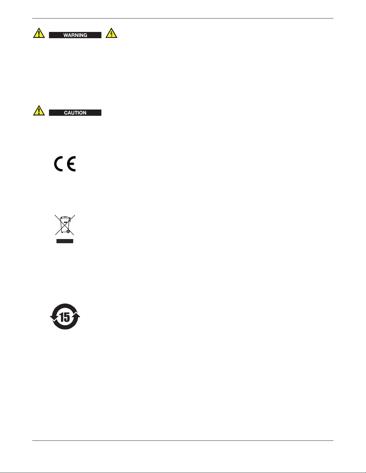
WARNING
EMC Directive Compliance
• Before turning on the instrument, you must connect the protective earth
terminal of the charger/adaptor to the protective conductor (mains) of the
power cord. The mains plug shall only be inserted into a socket outlet
provided with a protective earth contact. Never negate the protective action
by using an extension cord (power cable) without a protective conductor
(grounding).
• If there is any possibility that the ground protection could be impaired, you
must make the instrument inoperative and secure it against any unintended
operation.
• The instrument must only be connected to a power source corresponding to
the type indicated on the rating plate.
If a non-approved power supply cord not dedicated to Olympus products is
used, Olympus will not be able to ensure the electrical safety of the equipment.
CE (European Community)
This device complies with the
requirements of both directive
2004/108/EC concerning electromagnetic
compatibility and directive 2006/95/EC
concerning low voltage. The CE marking
indicates compliance with the above
directives.
WEEE Directive
In accordance with European Directive
2002/96/EC on Waste Electrical and
Electronic Equipment (WEEE), this
symbol indicates that the product must
not be disposed of as unsorted municipal
waste, but should be collected separately.
Refer to your local Olympus distributor
for return and/or collection systems
available in your country.
China RoHS
China RoHS is the term used by industry generally to describe legislation
implemented by the Ministry of Information Industry (MII) in the People’s
Republic of China for the control of pollution by electronic information
products (EIP).
The China RoHS mark indicates the
product’s Environment-Friendly Use
Period (EFUP). The EFUP is defined as the
number of years for which listed
controlled substances will not leak or
chemically deteriorate while in the
product. The EFUP for the DELTA has
been determined to be 15 years.
Note: The Environment-Friendly Use
Period (EFUP) is not meant to be
interpreted as the period assuring
functionality and product performance.
FCC (USA) Compliance
This equipment has been tested and found to comply with the limits for a
Class A digital device, pursuant to Part 15 of the FCC Rules. These limits are
designed to provide reasonable protection against harmful interference when
the equipment is operated in a commercial environment. This equipment
generates, uses, and can radiate radio-frequency energy, and if not installed
and used in accordance with the instruction manual, might cause harmful
interference to radio communications. Operation of this equipment in a
residential area is likely to cause harmful interference, in which case you will
be required to correct the interference at your own expense.
Warranty Information
Olympus guarantees your Olympus product to be free from defects in
materials and workmanship for a specific period, and in accordance with the
conditions specified in the Olympus Scientific Solutions Americas Inc. Terms and
Conditions available at http://www.olympus-ims.com/en/terms/.
The Olympus warranty only covers equipment that has been used in a proper
manner, as described in this instruction manual, and that has not been
subjected to excessive abuse, attempted unauthorized repair, or modification.
Inspect materials thoroughly on receipt for evidence of external or internal
damage that might have occurred during shipment. Immediately notify the
carrier making the delivery of any damage, because the carrier is normally
liable for damage during shipment. Retain packing materials, waybills, and
other shipping documentation needed in order to establish a damage claim.
After notifying the carrier, contact Olympus for assistance with the damage
claim and equipment replacement, if necessary.
This instruction manual explains how to safely operate your Olympus product.
The information contained herein is intended solely as a teaching aid and shall
not be used in any particular application without independent testing and/or
verification by the operator or the supervisor. Such independent verification of
procedures becomes increasingly important in line with the criticality of the
application. For this reason, Olympus makes no warranty, expressed or
implied, that the techniques, examples, or procedures described herein are
consistent with industry standards, nor that they meet the requirements of any
particular application.
Olympus reserves the right to modify any product without incurring the
responsibility for modifying previously manufactured products.
Technical Support
Olympus is firmly committed to providing the highest level of customer
service and product support. If you experience any difficulties when using our
product, or if it fails to operate as described in the documentation, first consult
the user’s manual, and then, if you are still in need of assistance, contact our
After-Sales Service. To locate the nearest service center, please contact the Sales
Representative the product was purchased from.
Trademarks
The Bluetooth® word mark and logos are registered trademarks owned by
Bluetooth SIG, Inc. and any use of such marks by Olympus Corporation is
under license.
26 Important Information — Please Read Before Use
Page 25

103076-01EN [U8998318], Rev. C, June 2014
Important Information — Please Read Before Use 27
Page 26

103076-01EN [U8998318], Rev. C, June 2014
Olympus Scientific Solutions Americas, 48 Woerd Avenue, Waltham, MA 02453, USA
www.olympus-ims.com
Printed in the United States of America • Copyright © 2011, 2013, 2014 by Olympus. All rights reserved.
All brands are trademarks or registered trademarks of their respective owners and third party entities.
Part ID: U8998318
*U8998318*
103076-01EN
Rev. C, June 2014
*103076-01EN*
 Loading...