

Page 1
DELTA
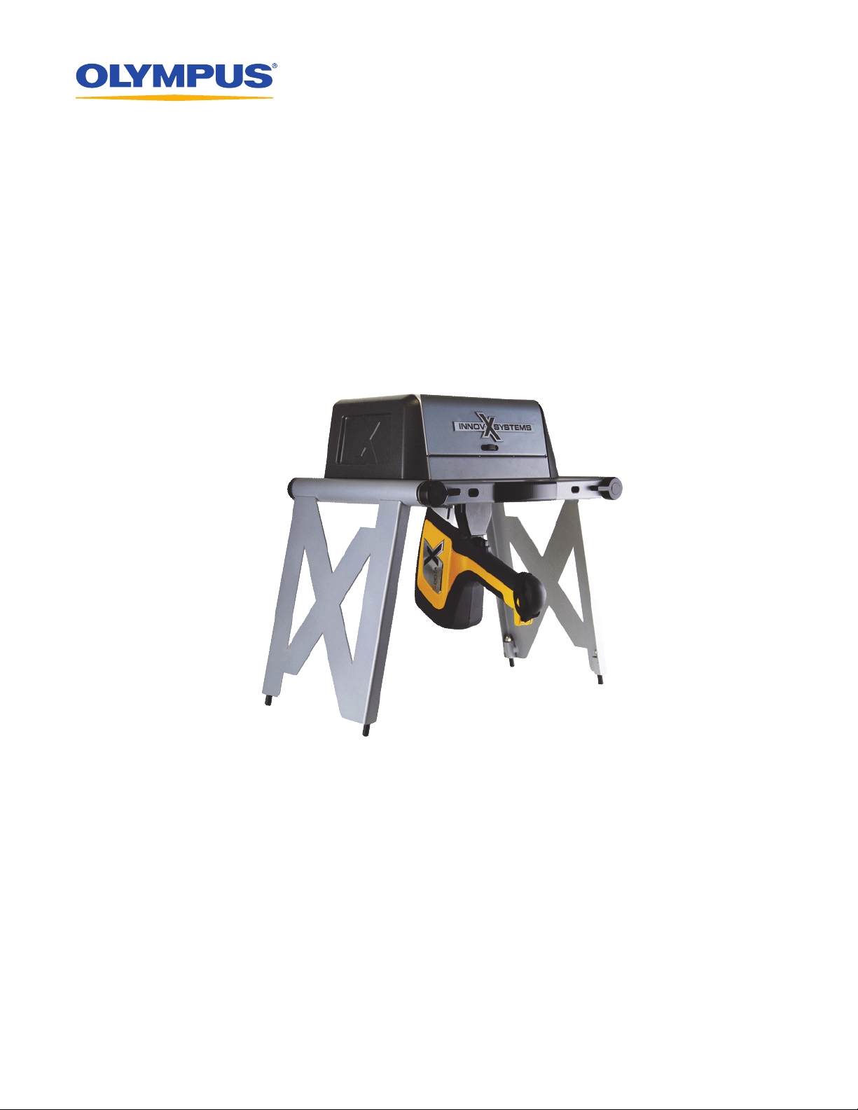
Portable Workstation
Quick Start Guide
International version
103158-01EN [U8998465]— Revision A
April 2012
Page 2

103158-01EN [U8998465], Rev. A, April 2012
1
2
3
4
3
4
CONTENTS
“Product Overview” ..................................................................................................................................................................Page 2
“Safety Information” ................................................................................................................................................................Page 3
“Physical Planning” ..................................................................................................................................................................Page 5
“Unfolding the Test Stand”.....................................................................................................................................................Page 6
“Configuring the Workstation” ..............................................................................................................................................Page 8
“Important Information — Please Read Before Use”.......................................................................................................Page 11
• Read the Important Information section carefully before handling this product.
• Refer to the DELTA User’s Manual (P/N: 103201) for more detailed information.
1. Product Overview
The DELTA Portable Workstation provides a fully shielded, rugged test stand for benchtop or remote-controlled testing. It
is comprised of:
• An A020-D test stand (U8990865)
• Any DELTA handheld analyzer model (including the Premium, Standard, or Classic)
In this configuration, the DELTA is controlled by the Olympus DELTA PC software. The open-beam handheld analyzer is
then converted into a safe closed-beam workstation.
1.1 Test stand
Component Key DELTA Portable Workstation — All models
1 Hinged lid
2 Test chamber
3Locking levers
4Hinged leg
2 Product Overview
Page 3
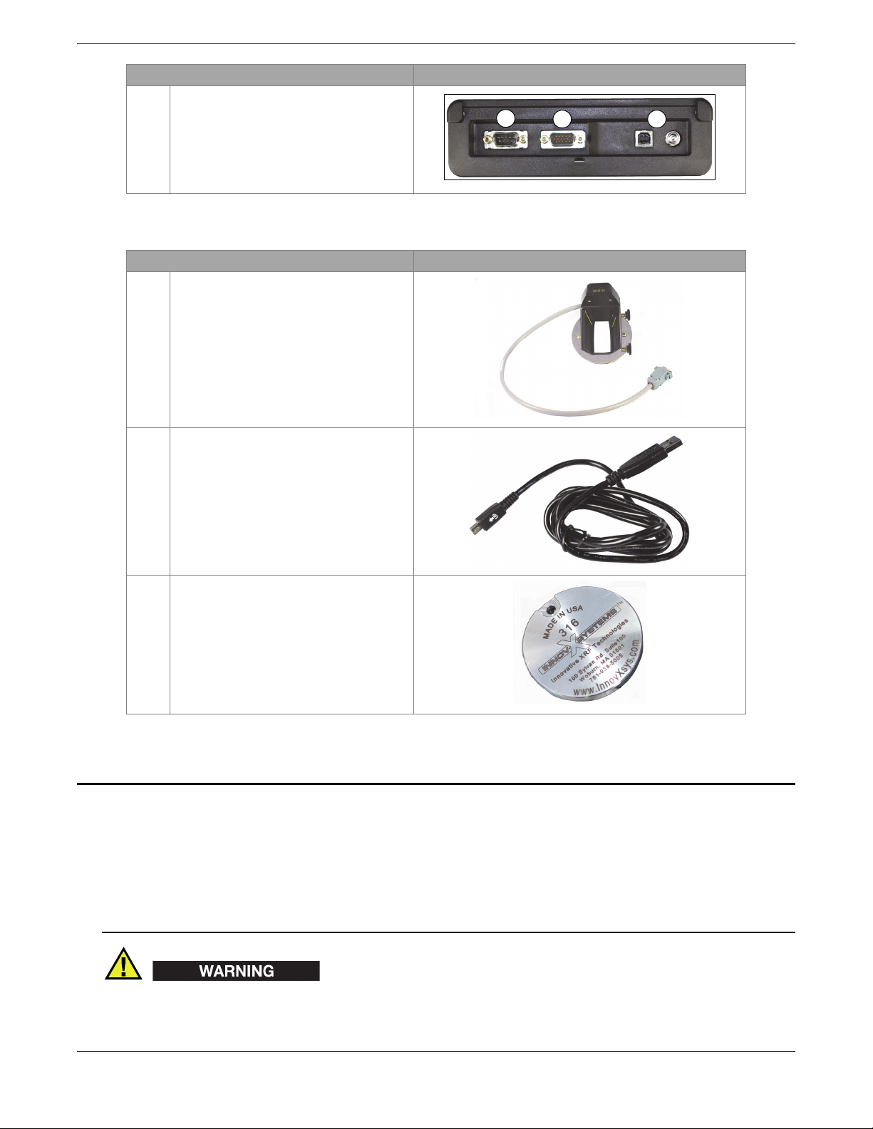
5 I/O panel (back of the test stand):
5a
5b 5c
a) Serial 9-pin D-Subminiature
connector
b) 15-pin D-Subminiature connector for
the probe adaptor
c) USB port and AC power
1.2 Accessories
1 DELTA probe adaptor with integrated
interface cable (P/N: U8990809)
2 USB cable (mini USB B to USB A
connector) [P/N: U8990455]
103158-01EN [U8998465], Rev. A, April 2012
Component Key DELTA Portable Workstation — All models
Component Key DELTA Portable Workstation — All models
3 Cal Check coupon (316 stainless steel)
[P/N: U8990448]
2. Safety Information
2.1 Radiation Safety Information
The DELTA Portable Workstation is a secure and dependable system when used in accordance with recommended testing
techniques and safety procedures. The radiation detected in the area outside the closed workstation is below the prescribed
limit for unrestricted areas.
• Olympus analyzers must only be used by trained and authorized operators in accordance with proper safety
procedures. Improper use may impair safety protection and cause potential harm to the user.
• Read all warning signs and labels.
Safety Information 3
Page 4
103158-01EN [U8998465], Rev. A, April 2012
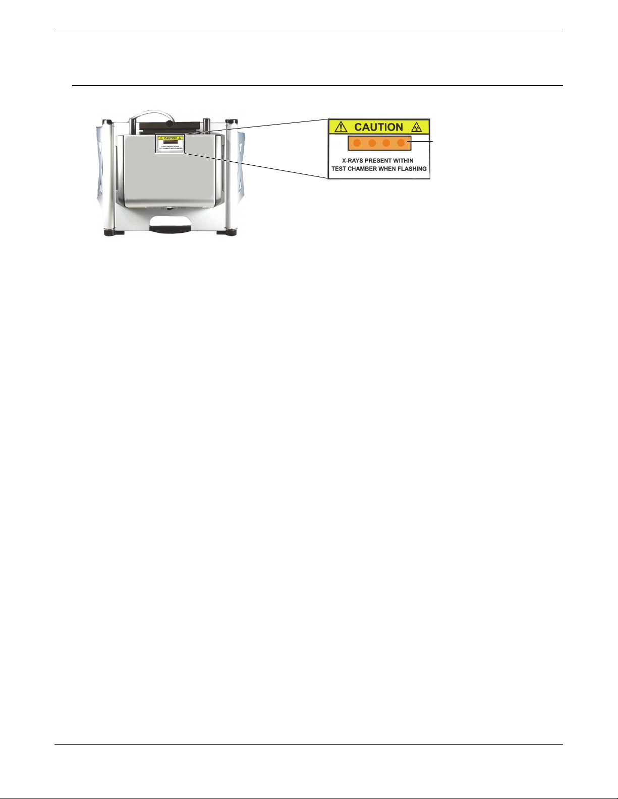
X-ray indicator cutout
• DO NOT USE the workstation if it exhibits any sign of damage, as doing so could result in unintentional emission of
stray radiation. If any damage is found or suspected, have a qualified professional perform a radiation safety test and
repair the workstation.
Figure 2-1 Caution radiation label on top of test stand
2.2 Safety Interlock Structure
This mandatory feature ensures that the DELTA Portable Workstation functions as a closed-beam X-ray system. To
establish a radiation-safe test chamber, the lid must be completely closed over the test platform. Until this condition is met,
no test analysis or Cal Check procedures can be initiated.
Examples of the safety interlock structure:
• If the lid is not closed (the safety interlock structure is not engaged for X-ray emission), the Cal Check button or Start
Test button is disabled (grayed out). It is not possible to force the X-ray On condition.
• If the lid is opened during an active test, the X-ray tube turns off immediately, and a “Test Aborted” message is
displayed.
The instrument turns off.
2.3 X-Ray Indicator
The X-ray indicator is located on the top of the test stand (see Figure 2-1 on page 4). This indicator consists of a fourelement amber LED array and has two key functions:
X-ray indicator continuously On (solid amber LED array)
This signifies that the X-ray tube is enabled.
X-ray indicator flashing On (blinking amber LED array)
This signifies that the analyzer is emitting X-ray radiation through the analysis window.
2.4 Software Proximity Sensor
Within one second of the start of a test, the analyzer detects the sample in front of the measurement window. If no sample
is detected, the X-rays automatically turn off.
2.5 Shut Down Under Emergency Conditions
If you believe that the analyzer is locked up in an On condition, and the amber LED array continues to blink, perform the
following procedure.
4 Safety Information
Page 5
103158-01EN [U8998465], Rev. A, April 2012
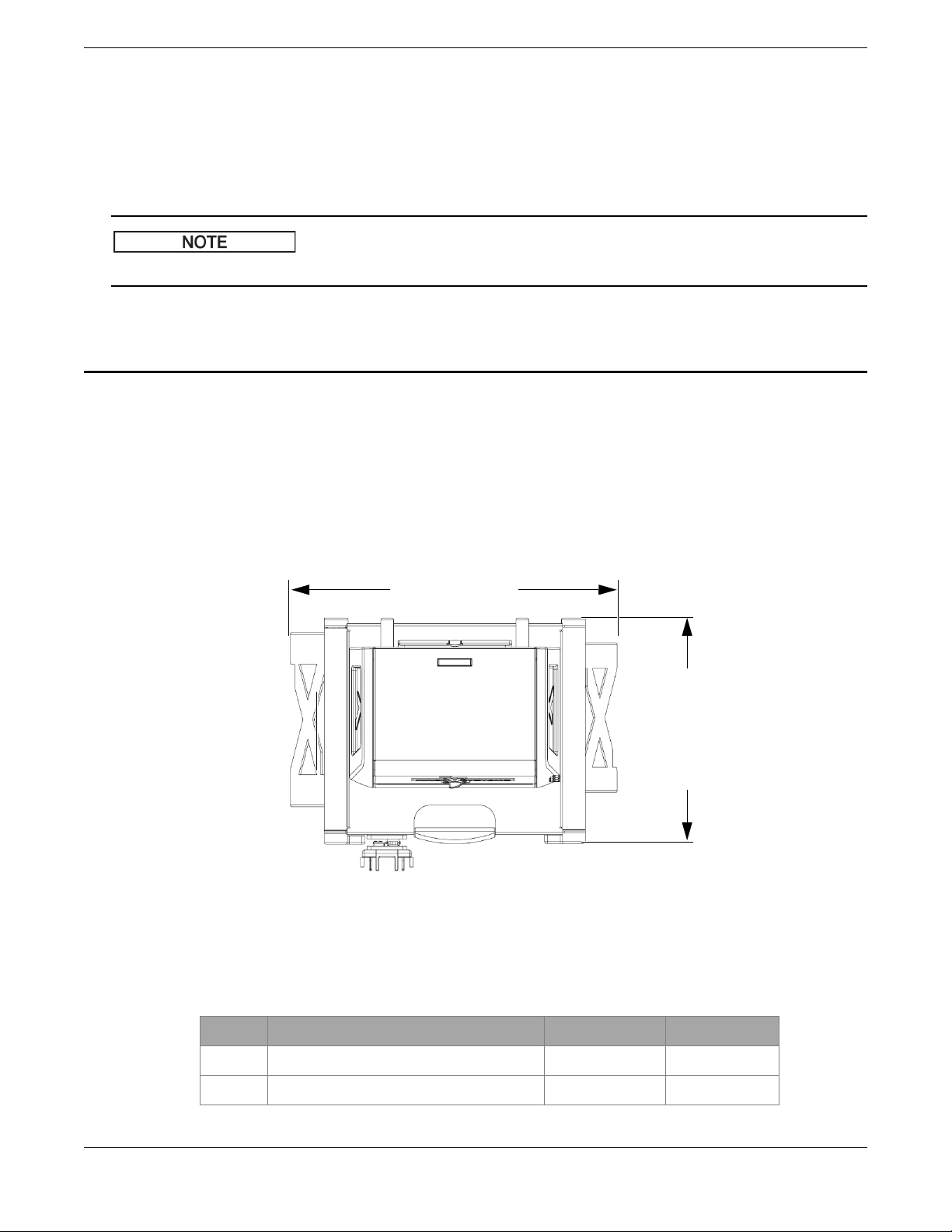
37.5 cm (14.75 in.)
52.2 cm (20.5 in.)
To shut down the analyzer in case of an emergency
Raise the lid (recommended method).
OR
Press the Stop Test button on the user interface.
OR
Unplug the probe adaptor cable from the test stand’s 15-pin D-Subminiature connector (see section 1.1 on page 2).
Opening the lid will not compromise the integrity of the test data.
3. Physical Planning
3.1 Workstation Footprint
The DELTA Portable Workstation weighs 8.9 kg (19.6 lb) with the probe adaptor, analyzer, and battery included.
To make a minimum footprint for the test stand, add at least 5.1 cm (2 in.) to the actual 52.1 cm (20.5 in.) width and 37.5 cm
(14.75 in.) depth. Plan for a 70 cm (27.5 in.) height when the lid is fully open (see Figure 3-1 on page 5). You should be able
to comfortably access the analyzer’s lid latch and test chamber.
Figure 3-1 Test stand: Top view (looking straight down)
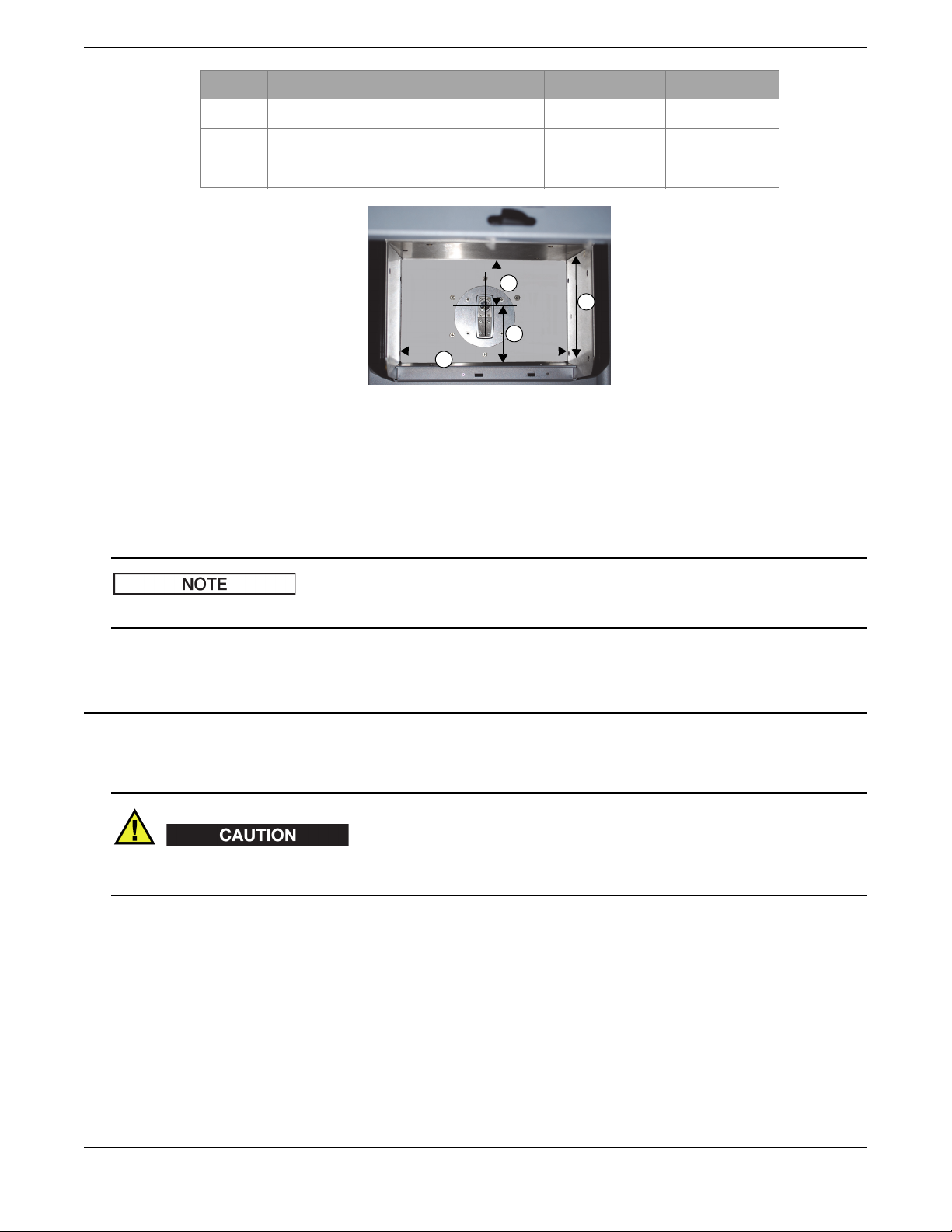
3.2 Test Chamber Dimensions
1 Width (side wall to side wall) 24.8 9.75
2 Depth (front to back) 15.6 6.125
Component key cm in.
Physical Planning 5
Page 6
103158-01EN [U8998465], Rev. A, April 2012
1
3
2
4
3 Center of window to front wall 9.5 3.75
4 Center of window to rear wall 7 2.75
5 Internal height (lid closed) [not shown] 12.4 4.875
Figure 3-2 Test chamber: Top view (looking straight down)
3.3 Electrical Requirements
Component key cm in.
You can use either the removable Li-ion battery (standard) or an AC adaptor (optional). You may also want to use the
DELTA docking station or a standard battery charger in the workstation area.
Both of the charging accessories require an AC power source.
4. Unfolding the Test Stand
To unfold the test stand
To avoid equipment damage, make sure that there is sufficient clearance when unfolding the test stand (see section 3.1 on
page 5).
1. Place the test stand on a table or a bench with its legs facing toward you (see Figure 4-1 on page 7).
2. Make sure that the locking levers are open (see Figure 4-1 on page 7).
6 Unfolding the Test Stand
Page 7
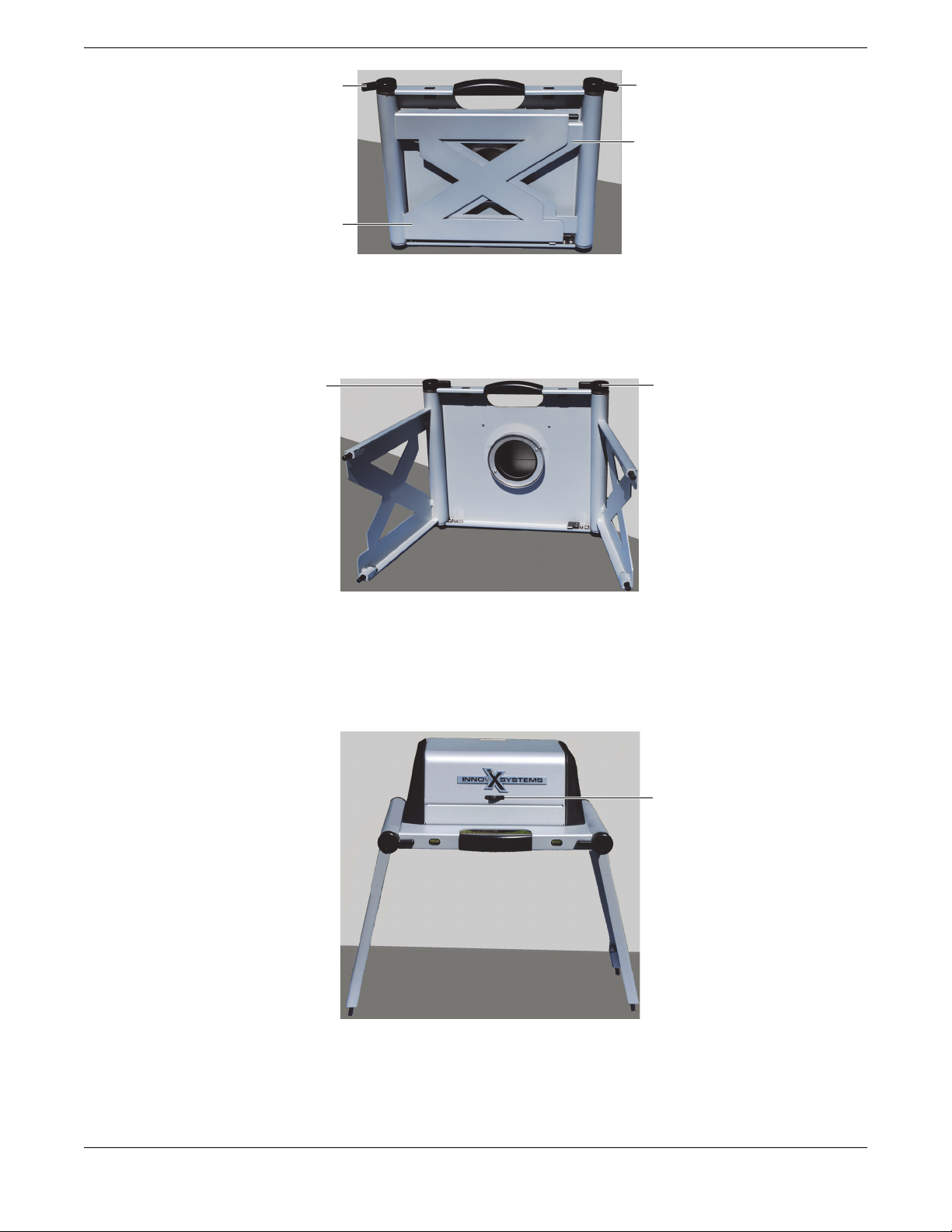
Figure 4-1 Folded test stand
Locking lever in the release position
Leg
Leg
Locking lever in the release position
Locking lever in the locked position
Locking lever in the release position
Latch
3. Swing the left legs out to their fully extended position.
4. Lock the legs into place using the two locking levers (see Figure 4-2 on page 7).
103158-01EN [U8998465], Rev. A, April 2012
5. Place the test stand upright.
6. If necessary, use leveling feet to stabilize the test stand.
7. Before opening the lid, slide the latch (see Figure 4-3 on page 7) to the right.
Figure 4-2 Legs locked into position
Figure 4-3 Lid latch
Unfolding the Test Stand 7
Page 8
103158-01EN [U8998465], Rev. A, April 2012
16-pin connector
Thumbscrews
DELTA measurement window
Probe-adaptor faceplate
5. Configuring the Workstation
Before using the workstation, you must do the following:
• Install the DELTA analyzer on a probe adaptor.
• Install the analyzer-adaptor assembly on the test stand.
To install the probe adaptor onto the DELTA analyzer
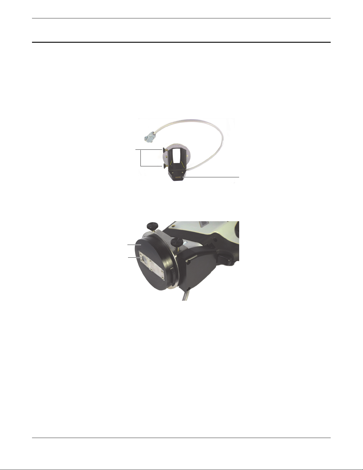
1. Loosen the two probe-adaptor thumbscrews.
2. Connect the DELTA analyzer to the probe adaptor’s 16-pin connector (see Figure 5-1 on page 8).
Figure 5-1 Probe adaptor
3. Make sure that the DELTA measurement window is flush with the probe-adaptor faceplate (see Figure 5-2 on page 8).
Figure 5-2 DELTA measurement window flush with the probe-adaptor faceplate
4. Tighten the two thumbscrews, making sure that the measurement window stays flush with the probe-adaptor
faceplate.
5. Install the analyzer-adaptor assembly on the test stand (see “To install the analyzer-adaptor assembly onto the test
stand”).
To install the analyzer-adaptor assembly onto the test stand
1. Unfold the test stand (see “To unfold the test stand”).
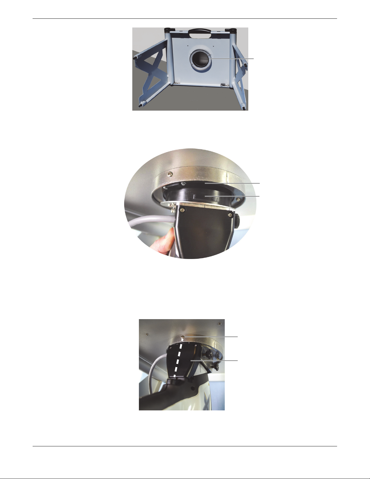
2. Position the test stand so that the locking fixture is accessible (see Figure 5-3 on page 9).
8 Configuring the Workstation
Page 9
103158-01EN [U8998465], Rev. A, April 2012
Locking fixture
Locking-fixture large notch
Probe-adaptor large tab
Alignment screw
Plastic housing
Figure 5-3 Test-stand locking fixture
3. Align the large tab of the probe adaptor with the large notch of the locking fixture (see Figure 5-4 on page 9).
Figure 5-4 Alignment with locking fixture
4. Make sure that the probe-adaptor faceplate is flush with the test chamber floor.
5. Carefully turn the analyzer-adaptor assembly counterclockwise until it locks.
The probe-adaptor plastic housing must be centered with the locking-fixture alignment screw (see Figure 5-5 on
page 9).
Figure 5-5 Analyzer-adaptor assembly installed on the test stand
6. Place the workstation in the upright position
Configuring the Workstation 9
Page 10
103158-01EN [U8998465], Rev. A, April 2012
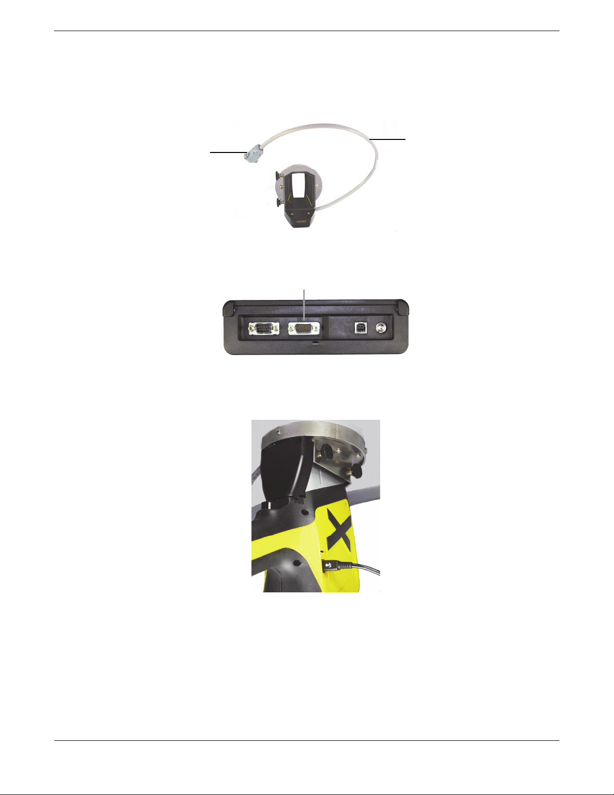
15-pin D-Subminiature connector
Interface cable
15-pin D-Subminiature connector
7. Connect to workstation to your PC (see “To connect the workstation to a PC”).
To connect the workstation to a PC
1. Connect the probe-adaptor interface cable (15-pin D-Subminiature connector) to the test stand’s I/O panel (see
Figure 5-6 on page 10 and Figure 5-7 on page 10).
Figure 5-6 Probe-adaptor interface cable
Figure 5-7 Test-stand I/O panel
2. Plug the USB cable mini USB B connector into the DELTA data port (see Figure 5-8 on page 10).
Figure 5-8 Mini USB B connector plugged into the analyzer data port
3. Plug the USB cable USB A connector into a PC USB port.
10 Configuring the Workstation
Page 11
Important Information — Please Read Before Use
Intended Use
The DELTA Portable Workstation is designed to perform identification and
analysis of elements from magnesium to uranium (Mg to U), depending on the
selected model, that are contained within test samples.
Do not use the DELTA Portable Workstation for any purpose other than
its intended use.
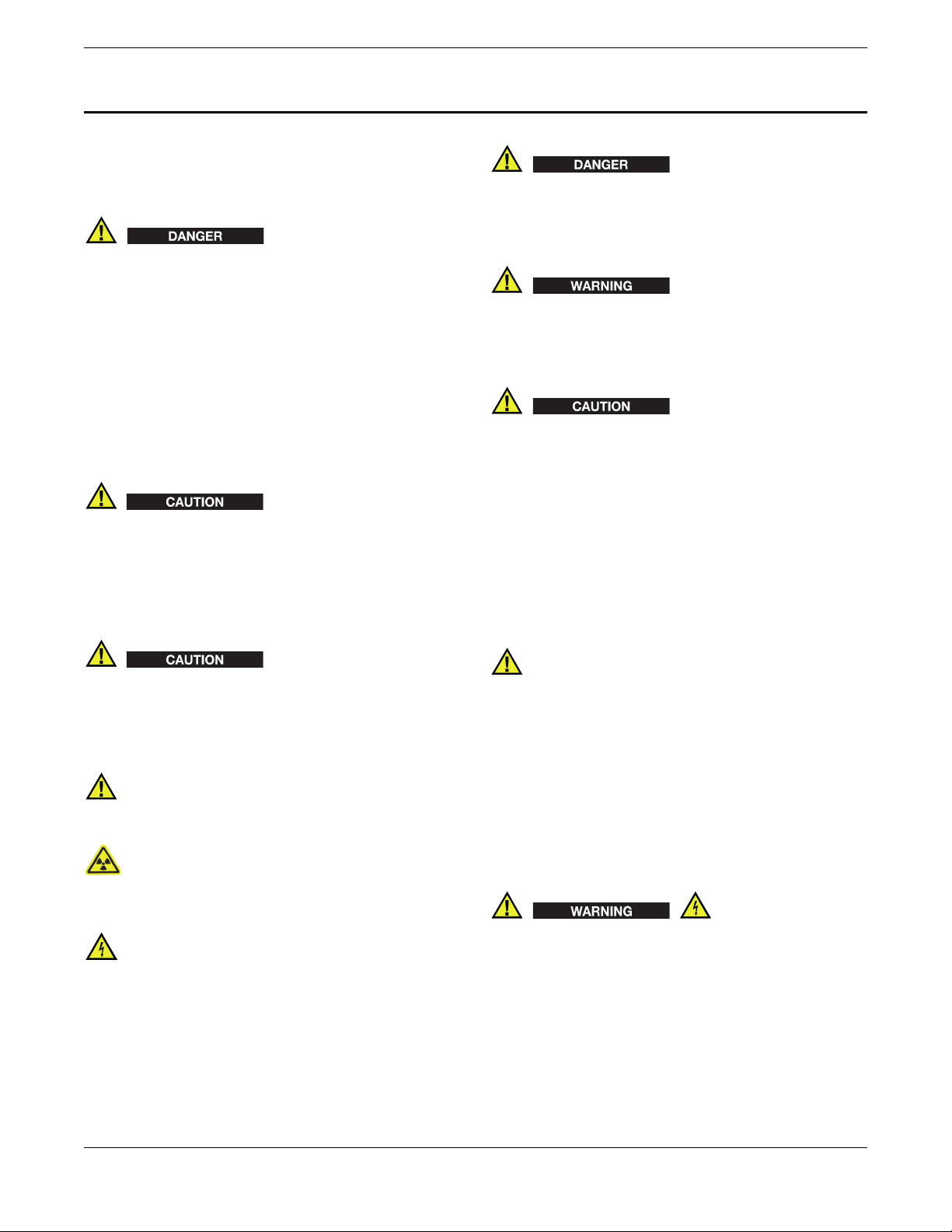
The DANGER signal word indicates an imminently hazardous situation. It
calls attention to a procedure, practice, or the like, which, if not correctly
performed or adhered to, could result in death or serious personal injury. Do
not proceed beyond a
fully understood and met.
DANGER signal word until the indicated conditions are
103158-01EN [U8998465], Rev. A, April 2012
Instruction Manual
This instruction manual contains essential information on how to use this
Olympus product safely and effectively. Before using this product, thoroughly
review this instruction manual, and use the product as instructed.
Keep this instruction manual in a safe, accessible location.
Instrument Compatibility
The DELTA Portable Workstation is primarily a self-contained unit. However,
it does have a series of I/O ports, which permits the user to connect compatible
peripherals and connect it to a PC. The unit derives its required DC input
power from the DELTA AC adaptor or battery pack.
Using incompatible equipment could cause malfunction and/or
equipment damage.
Repair and Modification
The DELTA Portable Workstation does not contain any user-serviceable parts,
apart from one exception: the measurement window. If the measurement
window is damaged, the window assembly should be replaced as soon as
possible. For more details, refer to the DELTA User’s Manual.
In order to prevent human injury and/or equipment damage, do not
disassemble, modify, or attempt to repair the instrument.
Safety Symbols
The following safety symbols might appear on the instrument and in the
instruction manual:
General warning symbol:
This symbol is used to alert the user to potential hazards. All safety messages
that follow this symbol shall be obeyed to avoid possible harm.
Radiation warning symbol:
This symbol is used to alert the user to the presence of potentially harmful
ionizing radiation generated within the XRF analyzer. All safety messages that
follow this symbol shall be obeyed to avoid possible harm.
High voltage warning symbol:
This symbol is used to alert the user to potential electric shock hazards greater
than 1,000 volts. All safety messages that follow this symbol shall be obeyed to
avoid possible harm.
Safety Signal Words
The following safety symbols might appear in the documentation of the
instrument:
The WARNING signal word indicates a potentially hazardous situation. It calls
attention to a procedure, practice, or the like, which, if not correctly performed
or adhered to, could result in death or serious personal injury. Do not proceed
beyond a
understood and met.
The CAUTION signal word indicates a potentially hazardous situation. It calls
attention to an operating procedure, practice, or the like, which, if not correctly
performed or adhered to, could result in minor or moderate personal injury,
material damage, particularly to the product, destruction of part or all of the
product, or loss of data. Do not proceed beyond a
the indicated conditions are fully understood and met.
WARNI NG signal word until the indicated conditions are fully
CAUTION signal word until
Safety
Before applying power to the DELTA Portable Workstation, verify that the
correct safety precautions have been taken (see the following warnings). In
addition, take note of the external markings on the instrument, which are
described in the “Safety Information” section.
Warnings
General Warnings
• Carefully read the instructions contained in this manual prior to turning on
the instrument.
• Keep the user’s manual in a safe place for further reference.
• Follow the installation and operation procedures.
• It is imperative to respect the safety warnings on the instrument and in the
user’s manual.
• If the equipment is used in a manner not specified by the manufacturer, the
protection provided by the equipment could be impaired.
• Do not install substitute parts or perform any unauthorized modification to
the instrument.
• Service instructions, when applicable, are for trained service personnel. To
avoid the risk of electric shock, do not perform any work on the instrument
unless qualified to do so. For any problem or question regarding this
apparatus, contact Olympus or an authorized Olympus representative.
• Before turning on the instrument, you must connect the protective earth
terminal of the charger/adaptor to the protective conductor (mains) of the
power cord. The mains plug shall only be inserted into a socket outlet
provided with a protective earth contact. Never negate the protective action
by using an extension cord (power cable) without a protective conductor
(grounding).
• If there is any possibility that the ground protection could be impaired, you
must make the instrument inoperative and secure it against any unintended
operation.
• The instrument must only be connected to a power source corresponding to
the type indicated on the rating plate.
Important Information — Please Read Before Use 11
Page 12
103158-01EN [U8998465], Rev. A, April 2012
If a non-approved power supply cord not dedicated to Olympus products is
used, Olympus will not be able to ensure the electrical safety of the equipment.
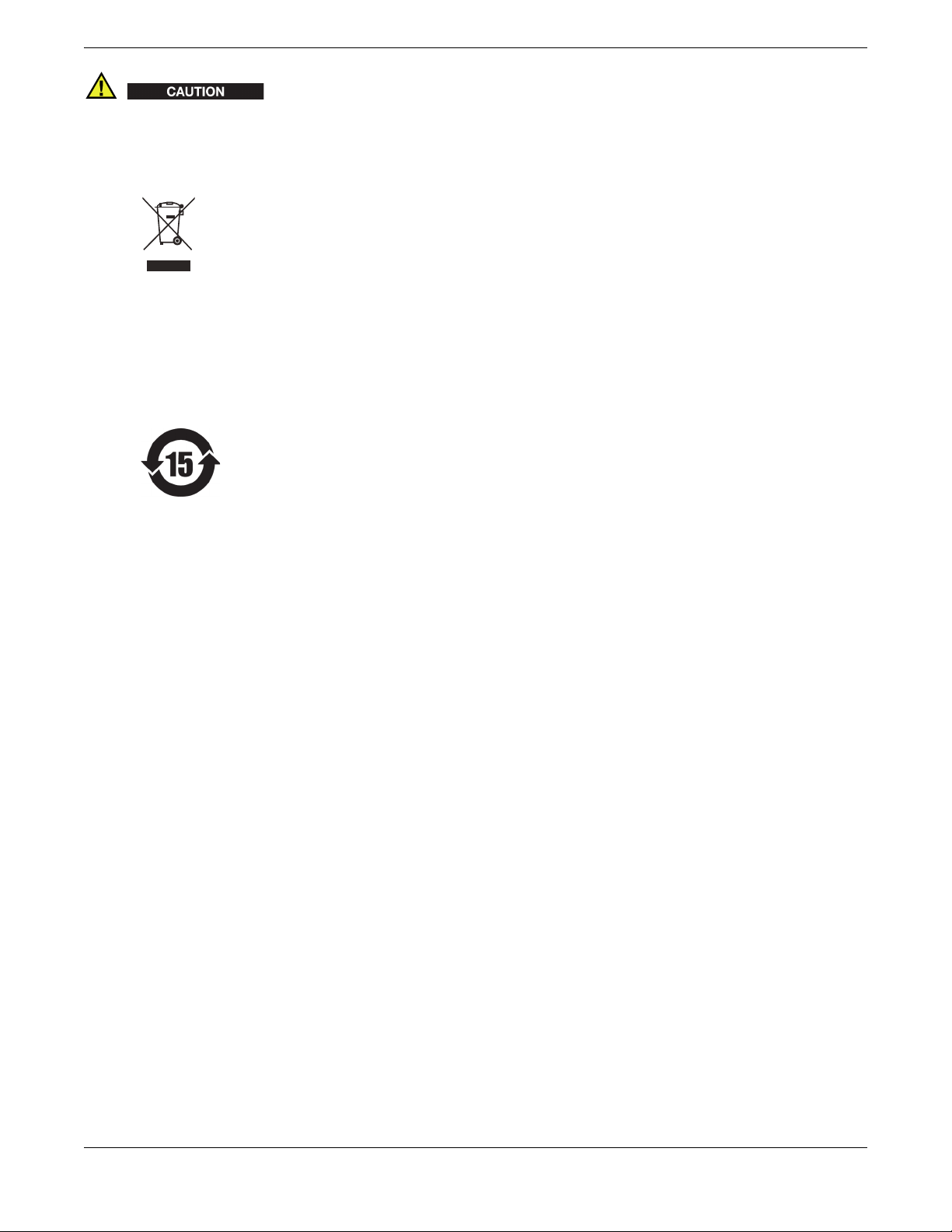
WEEE Directive
In accordance with European Directive
2002/96/EC on Waste Electrical and
Electronic Equipment (WEEE), this
symbol indicates that the product must
not be disposed of as unsorted municipal
waste, but should be collected separately.
Refer to your local Olympus distributor
for return and/or collection systems
available in your country.
China RoHS
China RoHS is the term used by industry generally to describe legislation
implemented by the Ministry of Information Industry (MII) in the People’s
Republic of China for the control of pollution by electronic information
products (EIP).
The China RoHS mark indicates the
product’s Environmental Friendly
Usage Period (EFUP). The EFUP is
defined as the number of years for
which listed controlled substances
will not leak or chemically
deteriorate while in the product. The
EFUP for the DELTA has been
determined to be 15 years.
Note: The Environment-Friendly
Usage Period (EFUP) is not meant to
be interpreted as the period assuring
functionality and product
performance.
EMC Directive Compliance
FCC (USA) Compliance
This equipment has been tested and found to comply with the limits for a
Class A digital device, pursuant to Part 15 of the FCC Rules. These limits are
designed to provide reasonable protection against harmful interference when
the equipment is operated in a commercial environment. This equipment
generates, uses, and can radiate radio frequency energy, and if not installed
and used in accordance with the instruction manual, might cause harmful
interference to radio communications. Operation of this equipment in a
residential area is likely to cause harmful interference, in which case you will
be required to correct the interference at your own expense.
EC Directive Compliance
This device complies with the requirements of Directive 2006/95/EC
concerning electrical equipment designed for use within certain voltage limits.
This device complies with the requirements of Directive 2004/108/EC
concerning electromagnetic compatibility when used in combination with
devices bearing the CE marking either on the products or in its instructions.
The above-mentioned Directives are in compliance with the designated
configuration for the EU region. Regions outside the EU that do not use the
same configuration are not required to comply with the above-mentioned
Directives.
Warranty Information
Olympus guarantees your Olympus product to be free from defects in
materials and workmanship for a period and in accordance with the conditions
specified in the Olympus NDT Terms and Conditions available at
http://www.olympus-ims.com/en/terms/.
The Olympus warranty only covers equipment that has been used in a proper
manner, as described in this instruction manual, and that has not been
subjected to excessive abuse, attempted unauthorized repair, or modification.
Inspect materials thoroughly on receipt for evidence of external or internal
damage that might have occurred during shipment. Immediately notify the
carrier making the delivery of any damage, because the carrier is normally
liable for damage during shipment. Retain packing materials, waybills, and
other shipping documentation needed in order to establish a damage claim.
After notifying the carrier, contact Olympus for assistance with the damage
claim and equipment replacement, if necessary.
This instruction manual attempts to teach the proper operation of your
Olympus product. The information contained herein is intended solely as a
teaching aid and shall not be used in any particular application without
independent testing and/or verification by the operator or the supervisor. Such
independent verification of procedures becomes more important as the
criticality of the application increases. For this reason, Olympus makes no
warranty, expressed or implied, that the techniques, examples, or procedures
described herein are consistent with industry standards, nor that they meet the
requirements of any particular application.
Olympus reserves the right to modify all products without incurring the
responsibility for modifying previously manufactured products.
Technical Support
Olympus is firmly committed to providing the highest level of customer
service and product support. If you experience any difficulties when using our
product, or if it fails to operate as described in the documentation, first consult
the user’s manual, and then, if you are still in need of assistance, contact our
After-Sales Service. To locate the nearest service center, please contact the Sales
Representative the product was purchased from.
Copyright Notice
Olympus NDT, Inc., 48 Woerd Avenue, Waltham, MA 02453, USA
Printed in the United States of America
rights reserved. All brands are trademarks or registered trademarks of their
respective owners and third party entities.
● © 2012 by Olympus NDT, Inc. All
12 Important Information — Please Read Before Use
 Loading...