

Page 1
INSTRUCTIONS
Single Use 3-Lumen Extraction Balloon V
B-V231P-A, B-V231P-B
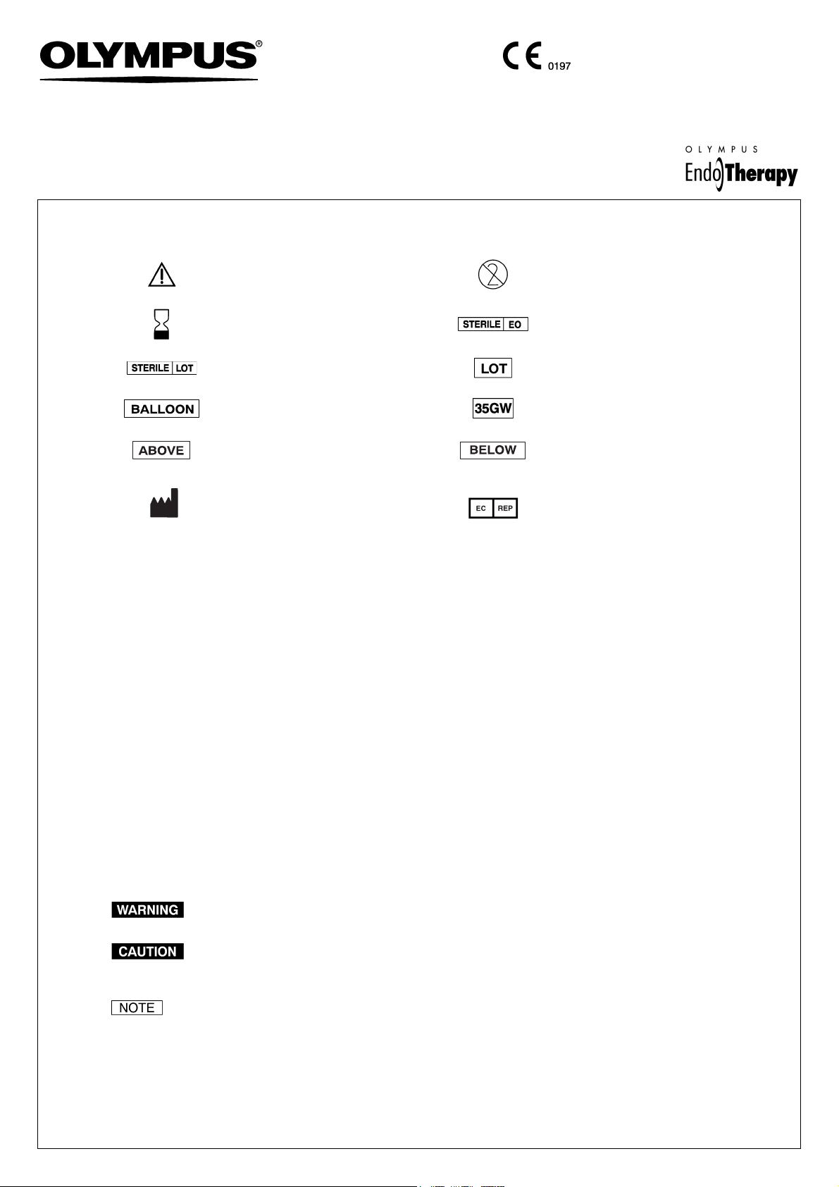
1 Symbols
Refer to instructions. Single use only
Use by (expiration date) Sterilized using ethylene oxide
Sterilization lot number Lot number
USA: CAUTION:
• This Product Contains Natural
Rubber Latex Which May Cause
Allergic Reactions.
• Federal law restricts this device to
sale by or on the order of a physician.
Air feeding port to inflate the balloon.
This instrument’s injection outlet is
above the balloon.
Manufacturer
Compatible with a ø 0.89 mm
(0.035 inch) guidewire.
This instrument’s injection outlet is
below the balloon.
Authorised representative in the
European Community
2 Intended Use
These instruments have been designed to be used with Olympus endoscopes to inject contrast media into the biliary or
pancreatic tract. They can also be used for retrieval of biliary or pancreatic stones. Do not use these instruments for any
purpose other than their intended use.
3 Instruction Manual
This instruction manual contains essential information on using these instruments safely and effectively. Before use,
thoroughly review this manual and the manuals of all equipment which will be used during the procedure and use the
instruments as instructed. If you have any questions or comments about any information in this manual, please contact
Olympus.
4 User Qualifications
The operator of this instrument must be a physician or medical personnel under the supervision of a physician and
must have received sufficient training in clinical endoscopic technique. This manual, therefore, does not explain or
discuss clinical endoscopic procedures.
5 Signal Words
Indicates a potentially hazardous situation which, if not avoided, could result in death or serious injury.
Indicates a potentially hazardous situation which, if not avoided, may result in minor or moderate injury. It
may also be used to alert against unsafe practices or potential equipment damage.
Indicates additional helpful information.
6 Natural Rubber Latex Medical Alert
This product contains natural rubber latex which may cause allergic reactions. The balloon at the distal end of the
insertion portion is made of natural rubber latex. Do not use this product on a latex-sensitive patient.
– 1 –
Page 2
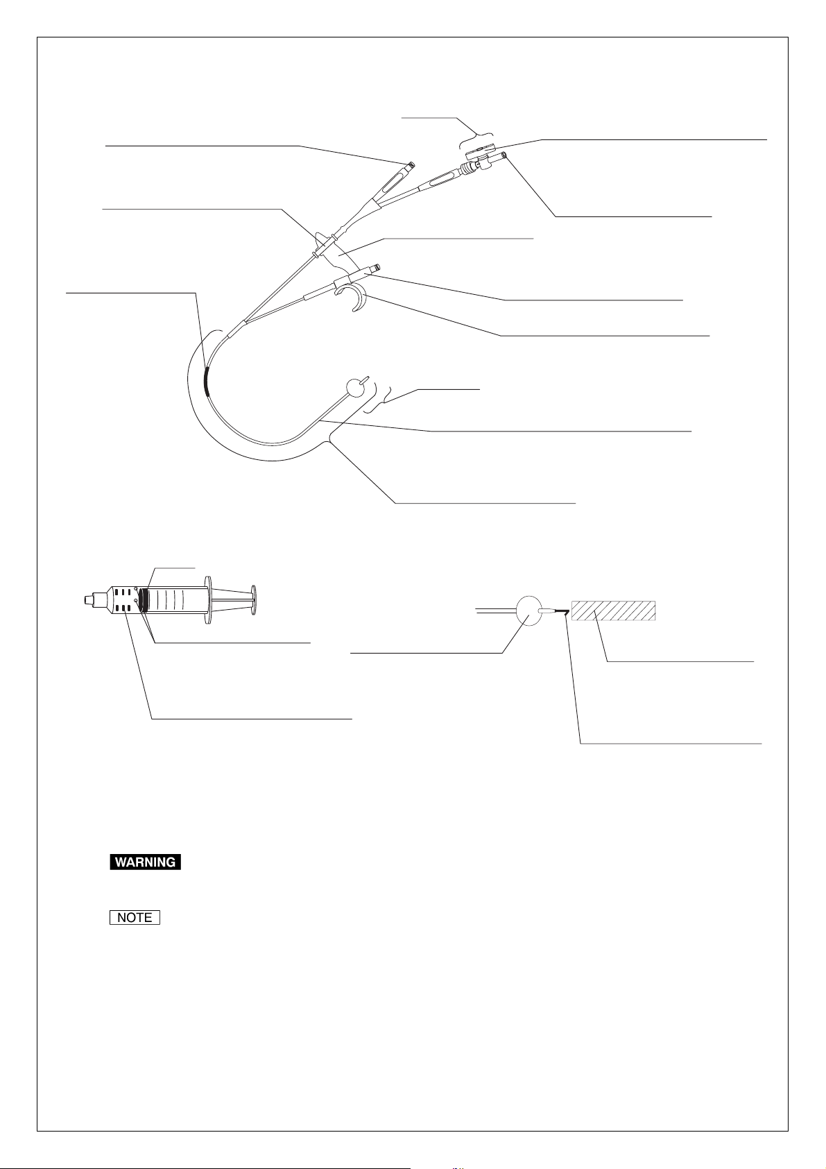
7 Nomenclature and Function
Stopcock
Injection port
Attach a syringe here to inject contrast
media, medical fluids or saline.
Connector
Attach the guidewire port here as
necessary.
Model reference label
Knob
Opens/closes a valve to control the airflow.
When the valve is open, the balloon can be
inflated. After inflation, the knob is turned to
close the valve and prevent air from escaping.
Air feeding port
Attach a syringe here to inflate
the balloon with air.
V marking
Gives the user an
approximate indication of
how far the instrument
has been inserted into the
endoscope.
Pre-measured syringes
(3 types for 8.5, 11.5 and 15 mm inflation)
Gasket
8.5
11.5
15.0
Prevents the syringe from
injecting more air than
necessary into the balloon.
Marks (For ø 15.0 mm inflation only)
Provide approximate position of the
distal end of Gasket for ø 8.5 mm or
ø 11.5 mm inflation.
Vent
Distal end
Tub e
The channel through which air is fed into the balloon
from the air feeding port and through which contrast
media, medical fluids or saline is injected.
Insertion portion/working length
Balloon
Inflated/deflated using a
syringe attached to the air
feeding port.
Guidewire port
Indicates compatible guidewire size.
Hook
Attached to the boot of endoscope or ET
control device (H-V100, sold separately).
Distal end
Light-proof cap
Prevents the latex rubber
balloon from deteriorating
when transported or stored.
Remove before use.
Distal stylet
The packaged instrument has distal
stylet attached.
Remove it from the instrument
before use.
8Specifications
Use this instrument only in combination with products recommended by Olympus. If combined with products
not recommended by Olympus, patient or operator injury, malfunction or equipment damage may result.
This instrument is compatible with ET control device (H-V100, sold separately). For further information on use
of the H-V100, refer to its instruction manual.
8.1 Operating environment
Ambient temperature: 10 – 40°C (50 – 104°F), Relative humidity: 30 – 85%,
Air pressure: 700 – 1060 hPa (0.7 – 1.1 kgf/cm
2
) (10.1 – 15.4 psia)
– 2 –
Page 3
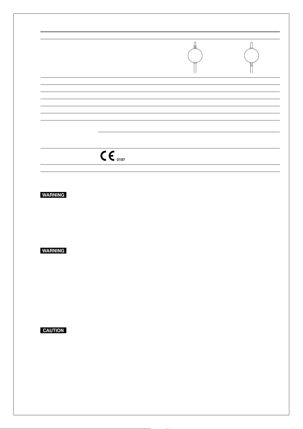
8.2 Specifications
Model B-V231P-A B-V231P-B
Shape of the balloon
Injection outlet location Above the balloon Below the balloon
Maximum insertion portion diameter (mm) ø2.7
Catheter O.D. (distal-proximal, mm (Fr)) 1.85 – 2.45 (5.5 – 7)
Working length (mm) 1900
Diameter after inflation (mm) ø 8.5/ø 11.5/ø 15.0
Compatible guidewire (mm (inch)) ø 0.89 (0.035)
Compatible Olympus
endoscopes
(All of these parameters
should be met.)
Medical Device Directive This device complies with the requirements of Directive
Others Compatible with ET control device
Model and length Working length less than 1400 mm
Channel inner diameter (mm)
(color code)
93/42/EEC concerning medical devices. Classification:
Class I
JF, TJF
ø 2.8, ø 3.2 (yellow)
ø 3.7, ø 4.2 (orange)
ø5.5 (pink)
9Storage
Do not store the sterile package containing the instrument in places where it will become damaged, wet or
improperly sealed. Otherwise, the sterility of the instrument may be compromised, which could pose an
infection control risk and/or cause tissue irritation.
Store the instrument in the sterile package at room temperature in a clean and dry environment. Do not store it in direct
sunlight.
10 Preparation, Inspection and Operation
• This product contains natural rubber latex which may cause allergic reactions. The balloon at the distal end of
the insertion section is made of natural rubber latex. Do not use this product on a latex-sensitive patient.
• When inspecting or using the instrument, always wear appropriate personal protective equipment, such as
eye wear, a face mask, moisture-resistant clothing and chemical-resistant gloves that fit properly and are long
enough so that your skin is not exposed. Otherwise, blood, mucus and other potentially infectious material
from the patient could pose an infection control risk and/or cause skin irritation.
• Do not use an instrument after the expiration date displayed on the sterile package. Doing so may pose an
infection control risk or cause tissue irritation.
• Before use, prepare and inspect the instrument as instructed below. Should the slightest irregularity be
suspected, do not use the instrument; use a spare instead. Damage or irregularity may compromise patient
or user safety, pose an infection control risk, cause tissue irritation, perforation, bleeding or mucous
membrane damage and may result in more severe equipment damage.
• Do not coil the insertion portion with a diameter of less than 150 mm. This could damage the insertion
portion.
• Never use excessive force to operate the instrument. This could damage the instrument.
10.1 Preparation Spare instrument
Always have a spare instrument available.
10.2 Inspection
Wear appropriate personal protective equipment in accordance with their respective instructions manuals.
– 3 –
Page 4

Inspection of the sterile package
Do not attempt to sterilize the instrument. This could pose an infection control risk, cause tissue irritation,
equipment damage or malfunction.
Inspect the sterile package for tears, inadequate sealing or water damage. If the sterile package shows any
irregularities, the sterile condition of the instrument may have been compromised. Do not use the instrument.
Appearance inspection
1. Remove the light-proof cap and the distal stylet from the distal end of the instrument.
2. Gently run your fingertips over the entire length of the insertion portion to check for any crushed areas, excessive
bends, broken areas or other damages.
3. Confirm that the distal end of the instrument appears exactly as shown in Sections 7 and 8 and is not damaged.
Making and inspecting the connections
• When attaching or removing the hook, do not hold far from the hook. This could damage the instrument.
• When attaching or removing the connector, do not hold far from the connector. This could damage the
instrument.
1. Push the hook onto the boot of the endoscope and confirm that it is secure (see Figure 1).
2. Remove the hook from the endoscope.
3. Confirm that the connector can be easily detached from and reattached to the groove of the guidewire port (see
Figure 2).
Connector
Boot
Hook
Stopcock
Figure 1
Groove
Figure 2
Guidewire port
Inspection of operation
• Do not inflate the balloon with any syringes other than attached pre-measured syringes. Otherwise, the
balloon may burst and the bursted pieces could remain in the duct.
• Do not inflate the balloon rapidly. Otherwise, the balloon may burst and the bursted pieces could remain in
the duct.
• Inflate the balloon with air only. Inflation with anything other than air may hinder expansion and contraction of
the balloon.
1. Make sure that the stopcock is securely attached.
2. Confirm that the stopcock’s knob is positioned as shown in Figure 3.
3. Connect the pre-measured syringe for 15.0 mm inflation onto the air feeding port (see Figure 3).
4. Slowly press the syringe’s plunger and confirm that the balloon inflates.
5. With the balloon inflated, turn the knob on the stopcock 90° clockwise to close the stopcock (see Figure 3).
6. Confirm that the balloon does not contract.
7. Turn the knob on the stopcock 90° counterclockwise to open the stopcock (see Figure 3).
8. Remove the syringe to deflate the balloon.
9. Insert the guidewire into the opening at the distal end of the tube. Confirm that the guidewire extends smoothly
and sufficiently out of the guidewire port.
– 4 –
Page 5

Inspecting irrigation
Use a contrast medium, medical fluid or saline solution intended for patient use when inspecting irrigation.
Other fluids may remain inside the channel and could pose an infection control risk or cause tissue irritation.
1. Inject contrast medium, medical fluid or saline into the instrument’s injection port using a sterile syringe (see
Figure 4). Confirm that the fluid comes out of the injection outlet at the distal end of the instrument.
2. Make sure that the contrast medium, medical fluid or saline does not leak from any area other than the injection
outlet at the distal end.
3. Connect another syringe containing air to the instrument’s injection port (see Figure 4). Inject air into the insertion
portion to discharge the contrast medium, medical fluid or saline solution.
Stopcock
Pre-measured syringe
10.3 Operation
Figure 3
Injection port
Figure 4
Knob
Air feeding port
Knob position when
the stopcock is open.
Syringe
• Do not insert the instrument into the endoscope unless you have a clear endoscopic field of view. If you
cannot see the distal end of the insertion portion in the endoscopic field of view or in x-ray images, do not use
it. This could pose a risk of perforation, bleeding or mucous membrane damage. It may also damage the
endoscope or instrument.
• Do not angulate the insertion portion of the endoscope or operate the forceps elevator while the distal end of
the insertion portion is extended from the distal end of the endoscope. This could result in perforation,
bleeding or mucous membrane damage.
• Do not force the distal end of the insertion portion against body cavity tissue. This could result in perforation,
bleeding or mucous membrane damage.
• Do not inflate the balloon with any syringes other than attached pre-measured syringes. Otherwise, the
balloon may burst and the bursted pieces could remain in the duct. This could result in mucous membrane
damage.
• Do not inflate the balloon rapidly. The balloon may burst and the bursted pieces could remain in the duct. This
could result in mucous membrane damage.
• Inflate the balloon with air only. Inflation with anything other than air may hinder contraction of the balloon and
make it impossible to withdraw the instrument from the body cavity.
– 5 –
Page 6

Inserting into the endoscope
• Confirm that the balloon is completely deflated when inserting the instrument into the endoscope. If the
balloon is inflated, the distal end of the instrument may extend from the distal end of the endoscope abruptly.
This could cause patient injury, such as perforation, bleeding or mucous membrane damage, and could
damage the endoscope and/or instrument.
• When using a guidewire, hold the guidewire while inserting the instrument. Otherwise, the guidewire will
move with the instrument. This could cause patient injury, such as perforation, bleeding or mucous
membrane damage.
• Be sure to raise the forceps elevator to its maximum height. If the forceps elevator is down, you will not be
able to see the distal end of the insertion portion in the endoscopic field of view. This could cause patient
injury, such as perforation, bleeding or mucous membrane damage.
• Do not force the instrument if resistance to insertion is encountered. Reduce the angulation (or lower the
forceps elevator if applicable) until the instrument passes smoothly. The use of excessive force causes
patient injury, such as perforation, bleeding or mucous membrane damage. It may also damage the
endoscope and/or instrument.
• Do not advance or extend the instrument abruptly. This could cause patient injury, such as perforation,
bleeding or mucous membrane damage. It could also damage the endoscope and/or instrument.
• When inserting the instrument into the endoscope, hold it close to the biopsy valve and keep it as straight as
possible relative to the biopsy valve. Otherwise, the insertion portion could be damaged.
• Do not excessively curve the instrument forcibly. Excessive bending force could prevent smooth passage of
the guidewire.
1. Raise the forceps elevator to its maximum height.
2. Carefully insert the instrument into the biopsy valve.
3. When using a guidewire, hold the guidewire in position and insert the instrument into the endoscope along the
guidewire.
4. When the distal end of the insertion portion contacts the forceps elevator, lower the forceps elevator.
If the entire V marking is outside the biopsy valve, the distal end of the inserted instrument has not advanced
as far as the endoscope’s forceps elevator. When the distal end of the V marking comes near the biopsy
valve, the distal end of the instrument is very close to the forceps elevator.
5. Advance the instrument another 20 mm and raise the forceps elevator. You will see the distal end of the instrument
in the endoscopic field of view.
If the forceps elevator is down, you will not see the distal end of the instrument in the endoscopic field of view.
It will only be possible to see the instrument if you raise the forceps elevator gradually.
Attaching or removing the hook
When attaching the hook to the boot of the endoscope, be careful not to make the guidewire port face a
patient. When the instrument is used with the guidewire, the end of the guidewire could contact the patient’s
face. This could cause patient injury.
When attaching or removing the hook, do not hold far from the hook. This could damage the instrument.
The control section of this instrument can be attached to the endoscope or ET control device using the hook.
1. Push the hook onto the boot of endoscope or ET control device until it clicks (see Figure 1).
2. Confirm that the hook is secured and the control section of instrument can be attached to the endoscope or ET
control device.
3. When removing the hook, pull it gently.
– 6 –
Page 7

Attaching or removing the connector
When attaching or removing the connector, do not hold far from the connector. This could damage the
instrument.
When removing the connector from the guidewire port, the air feeding port and the injection port can be
separated from the guidewire port.
1. Detach the connector from the guidewire port if necessary (see Figure 2).
2. When attaching the connector to the guidewire port, push it into the groove until it clicks (see Figure 2).
Radiography, injecting medical fluid and retrieval
Do not operate the instrument abruptly or with excessive force when retrieving a foreign object. Otherwise,
patient injury, such as bleeding or mucous membrane damage, may occur or the balloon may burst and the
bursted pieces could remain in the duct.
1. Connect a sterile syringe filled with a contrast medium, medical fluid or saline solution to the injection port. Inject
the fluid until the air inside the tube is forced out.
2. Insert the distal end of the instrument into the target site.
3. Confirm that the stopcock is open (see Figure 3).
4. Select a pre-measured syringe according to the size of the balloon being used (Balloon size is indicated on each
syringe).
5. Pull the plunger of the syringe until it stops and mount the syringe onto the air feeding port.
6. Push the plunger until it stops to inject air into the balloon.
When using the pre-measured syringe for ø 15.0 mm inflation, the marks on the syringe provide approximate
position of the distal end of Gasket for ø 8.5 mm or ø 11.5 mm inflation.
7. Turn the knob on the stopcock 90° clockwise to close the stopcock.
8. Depress the syringe’s plunger to inject the fluid.
9. Pull the instrument to clear the foreign object.
Withdrawing the instrument from the endoscope
Do not withdraw the instrument from the endoscope quickly. This could scatter blood, mucus or other patient
debris and pose an infection control risk.
• Do not withdraw the instrument from the endoscope while the balloon is inflated. This could damage the
endoscope and/or instrument.
• When using an endoscope equipped with a forceps elevator, do not withdraw the instrument from the
endoscope if the forceps elevator is up. This could damage the instrument.
• If resistance is too strong and withdrawal is difficult, adjust the angle of the endoscope until the instrument
can be withdrawn smoothly. Forcible withdrawal could damage the instrument and/or endoscope.
• Do not withdraw the syringe’s plunger in order to deflate the balloon when the stopcock valve is closed. The
balloon cannot be deflated if the stopcock valve is closed, even if the syringe’s plunger is withdrawn.
1. Turn the knob on the stopcock 90° counterclockwise to open the stopcock (see Figure 3).
2. Pull out the pre-measured syringe’s plunger to deflate the balloon.
3. Lower the forceps elevator.
4. Withdraw the instrument from the endoscope.
When the entire V marking is outside the biopsy valve, the distal end of the instrument has been retracted
into the endoscope’s instrument channel, and is now proximal to the forceps elevator. When using an
endoscope with the guidewire stabilizing function, the forceps elevator may now be raised to stabilize the
guidewire.
– 7 –
Page 8

11 Disposal
• After use, dispose of the instrument in an appropriate manner. If it is not properly disposed of, it could pose
an infection control risk.
• The instrument is a single-use, disposable item. Do not reuse or attempt to sterilize it. Reusing the instrument
could pose an infection control risk, cause tissue irritation or malfunction.
After using the instrument, dispose of it in an appropriate manner.
Manufactured by
2951 Ishikawa-cho, Hachi oji-shi, Tokyo 192-8507, Japan
Fax: (042)646-2429 Telephone: (042)642-2111
3500 Corporate Parkway, P.O. Box 610 Center Valley, PA 18034-0610, U.S.A.
Fax: (484)896-7128 Telephone: (484)896-5000
117071, Moscow, Malaya Kaluzhskaya 19, bld. 1, fl.2, Russia
Fax: (095)958-2277 Tel ephone: (095)958-2245
491B, River Valley Road #12-01/04, Valley Point Office To wer, Singapore 248373
Fax: 6834-2438 Telephone: 6834-0010
GK4967 05
Distributed by
(Premises/Goods delivery) Wendenstrasse 14-18, 20097 Hamburg, Germany
(Letters) Postfach 10 49 08, 20034 Hamburg, Germany Telephone: (040)237730
One Corporate Drive, Orangeburg, N.Y. 10962, U.S.A.
Fax: (845)398-9444 Telephone: (845)398-9400
8F, Hyundai Marines Bldg., 646-1, Yeoksam-Dong, Kangnam-Gu, Seoul 135-080 Korea
Fax: (02)6255-3499 Telephone: (02)1544-3200
31 Gilby Road, Mount Waverley, VIC., 3149, Australia
Fax: (03)9543-1350 Telephone: (03)9265-5400
©2004 OLYMPUS MEDICAL SYSTEMS CORP. All rights reserved.
– 8 –
KeyMed House, Stock Road, Southend-on-Sea, Essex SS2 5QH,
United Kingdom
Fax: (01702)465677 Telephone: (01702)616333
5301 Blue Lagoon Drive, Suite 290 Miami, FL 33126-2097, U.S.A.
Fax: (305)261-4421 Telephone: (305)266-2332
Room 1202, NCI Tower, A21 Ji anguomenwai Avenue Chaoyang
District Beijing 100022 PRC
Fax: (10)6569-3545 Tel ephone: (10)6569-3535
Printed in Japan 20050223 *0000
 Loading...