

Page 1
OLY MPUS POLARIZING MICROSCOPE
I
MODELS
BHA
-P&B;H.-P
ATTACHMENT
Page 2
This
i
>
!
instruction rnancral has been written for the use
Modcl
manual carefully in order to familiarize yourself fully
polarizing attachment so
CHA-P
and Polarizirl!j Attach~nent Model
lhal
you
can
ob~an
IMPORTANT
the
of
131-I-P.
with
best
performance
the Olyn~pus Polarizing Microscope
It
is
recommended
the use
of
Ihe microscope on the
and
~ffectiveness.
to
r-ead
the
!,
I
t
Observe
the
following points carefully:
Operation
1.
Always
2.
Avoid exposure of
3.
Only
Do
ously, which
4.
Ascertain that
local mains voltage.
5.
Disconnect
Maintenance
1.
Lenses
wiped off by means
prints deposited
xylene, alcohol or ether.
2.
Do
parts, especially, should
handle
use
the
not twist the two coarse adjustment
must
not use organic solutions
the microscope
the
microscope
tension adjustment ring for altering the tension
might
cause damage.
the
voltage selector switch on the base plate is set
the
line cord frorn
always
on
be
of
the
with
the
care
it
deserves, and avoid abrupt motions.
to
direct sunlight.
knobs
in
the
AC
power outlet for fuse replacement.
kept
clean. Fine dust
an air blower
lens
surfaces
be
cleaned with a neutral detergent.
lo
or
wipe
a
with
on
clean
brush.
yaclzs moistened
the surfaces of various components.
dust
the
lens
and vibration.
of
the coarse adjustment.
opposite directions sirnultane-
to
conform wit11
surfaces
Carefi~lly wipe off oil
should
with
be
blown or
or
a
small amount
finger-
Plastic
the
of
3.
Never disassemble the rnicroscope for repair
4.
The microscope should
possible, it slioi~ld
eyepieces in
5.
Disconnect the line cord
a
desiccator, containing cjcsiccants.
be
stored
be
covered with
frorn
the
in
AC
its container immediately aftel- use. li this
ti
vinyl dust cover.
power
soirrce before
It
is best
fuse
to
kcap
objectives and
replacement.
is
not
Page 3
CONTENTS
t.
STANDARD
it.
NOMENCLATURE
I1
I. ASSEMBLY
1V.
IDENTIFICATION AND FUNCTION OF VARIOUS
EQUIPMENT
.
.
.
.
.
.
.
. .
. . .
.
.
.
. . . .
. . . . . . . . . .
.
. . .
.
. . .
.
. . . . . . .
. .
. . . . .
COMPONENTS
.
.
.
. . .
.
. .
.
.
.
.
.
V. OPERATION
1.
Electric System
2,
lnterpupillary Distance
3.
Light Path Selection
4.
Centering
5.
Centering
6.
Centering
7.
Use of
8.
Focusing Adjustment
9.
Orthoscopic Observation
10.
Conoscopic Observation
11.
Photomicrography
VI. OPTICAL
DATA
.
.
. . . . .
the Condenser
the
Stage
the
Objectives
Iris
Diaphragms
.
.
. . .
and
Diopter
.
.
.
. . .
. . .
. . . .
. .
.
,
. .
.
.
. . . . .
Adjustments
.
.
.
.
.
.
. . .
.
.
. .
. . . . . . . . .
. . . . .
.
. . . . . . . . .
.
.
. . .
.
. . . . . . .
.
. .
.
.
.
.
.
.
. . .
,
.
. . .
. .
. . .
.
.
.
.
.
. . .
. . . . .
.
.
VII. TROUBLESHOOTING.
. . . . . t . . . .
.
.
.
.
.
.
. .
.
Page 4
1.
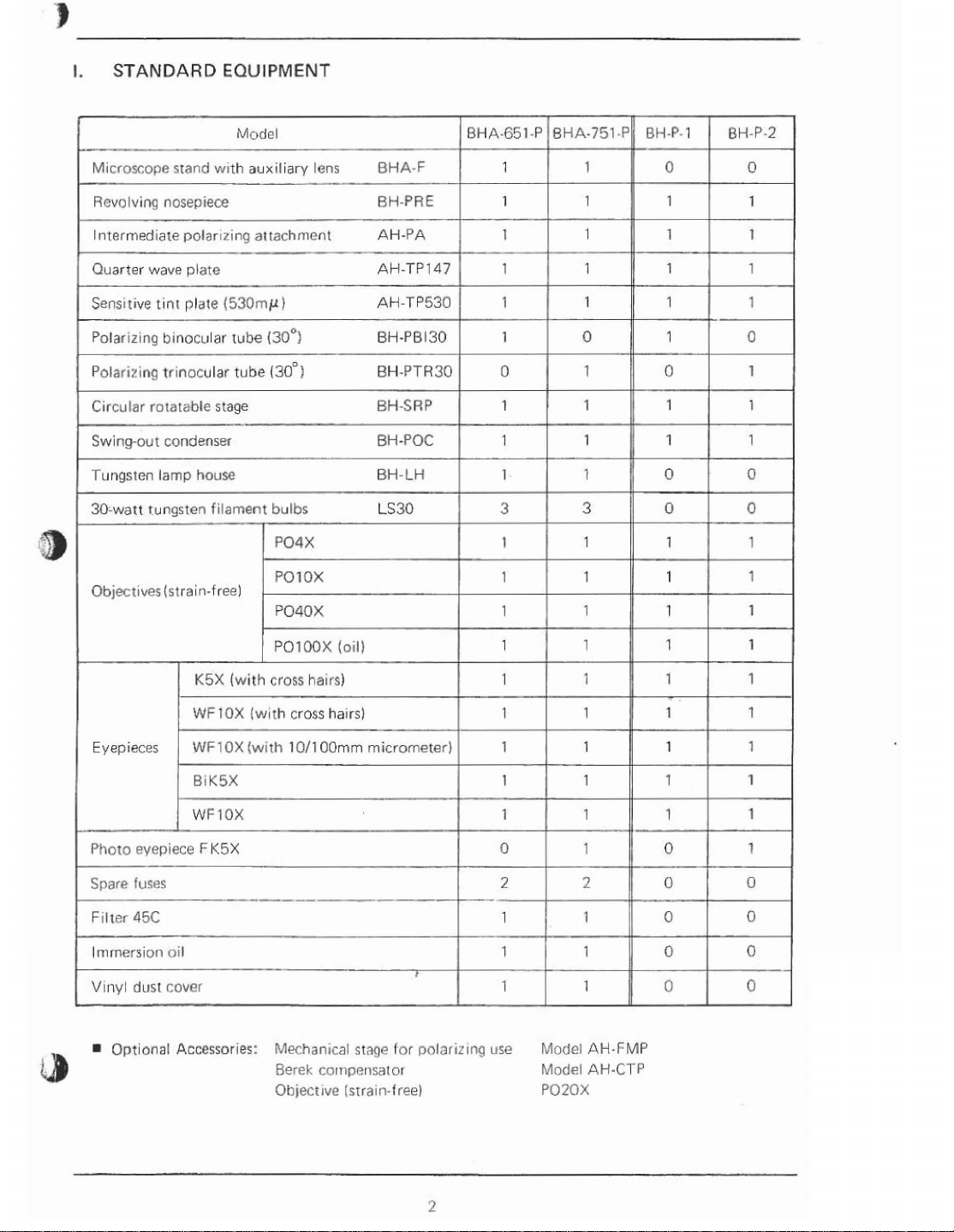
STANDARD
-
EQUIPMENT
Microscope
Rcvo
l~itermediate
Quarter
Sensrt~ve
Polarlztng
Polari~lnq
Circular
Swing-out
Tungsten
30-watt
Objecrrves
lving
nosepiece
wave
tint
b~necular
tr~nocular
rotatable
condenser
lamp
tungsten
(strain-free)
stand
Model
wrth
polarizing
plate
plate
(53OrnpCI)
tube
tube
stage
house
filament
aux~lrary
a~tachmenl
lens
(30~)
(30~1
bulbs
PO4
X
POIOX
P040X
BHA-F
RH-PRE
AH-PA
AH-TPI47
AH-TP530
BH-PB
130
BH-PTH30
BH-SRP
BH
-POC
BH-LH
LS30
BHA-651-P
1
1
1
1
pp
1
1
0
1
1
1
3
1
'
1
1
BHA-751-P
J
1
1
BH-P-1
I
I
0
1
1
1
1
0
1
1
111
1
3
1
1
1
1
0
1
0
0
1
1
1
BH-P-2
0
1
1
0
1
1
1
0
0
1
1
1
Eyepieces
Photo
Spare
F~lter
Immersion
V~nyt
-
Optional
K5X
WFlOX
WF1
BIKSX
WFlOX
~yep~ece
fuses
F
45C
nil
dust
cover
Accessories:
(with
OX
K5X
PO1
cross
(with
(with
Mechanical
Berek
Qhjectivc
00X
Iollj
hatrs)
cross
ha~rs}
1011
00mm
cornpensalor
(srrain-free)
micrometer)
stage
for
-
I
polarizing
1
1
1
1
1
1
0
2
1
1
1
use Model
Modsl
P020X
1
1-1
1
1
1
1
2
1
'
1
t
1
1
7
1
1
11
10
-
0
I
I0
1
0
,!
\
0
1
1
1
0
0
0
0
AH-FMP
AH-CTP
Page 5
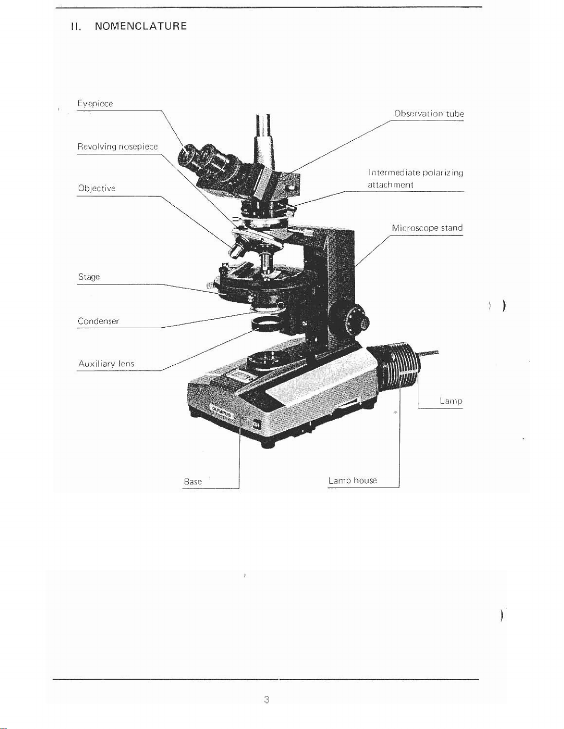
II.
NOMENCLATURE
Base
1
Page 6
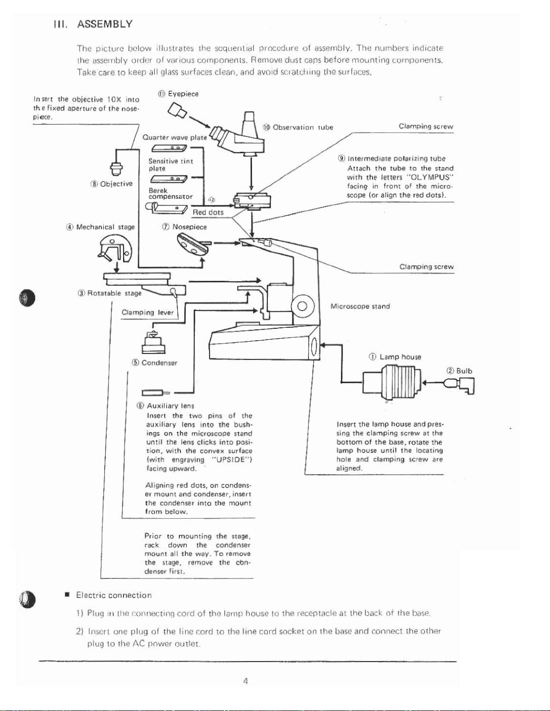
Insert
the
piece.
Ill.
the
fixed
objective
aperture
(TI
ASSEMBLY
Tfic
141ctl1re
the
assembly
Take
cars
of
$1
i~clow 11111~t~atCs the
cjrrlnr
lo
Ireep
10X
inlo
the
nose-
Objective
"I
Mechanical
stage
ol
all
glaqs
0
Quarter
Sensitive
plate
vilrlous
colnponenls. Rel~iove
surfaces cleat),
Eyepiece
wave
plate
rint
--
Berek
compensator
I
0
Nosepiece
scq~leritidl
and
\
k---
~prncodr~r
dust
avalcl
si.4
al~4t111g
@
Qbservat~on
1%
ol
caps
assernbly
T!ie
before mounting
tlie
srrr
faces.
tu11e
@j
lntermedrate Dolarizing
Attach
wrth
rhe
facing
scope
nt~nhrvc
Lurnpunents.
the
tube
letters
in front
(or
align
~ndtcrlt~
Clamping
tube
to
the
"OLYMPUS"
of
the
red
micro-
dots).
the
screw
stand
Rotatable
stage
Insert
aux~liary
rng5 on
unt~l
the
tion.
w~th
(with
engraving
tac~ng
upward.
Align~ng
er
mount
the
condenser
Prior
to
rack
down
mount
all
the
stage,
denser
firs[.
the
two
lens ~nto
the
microscoae
lens
clicks
the
red dots,
and
condenser,
inro
mounting
the
the
way.
(*move
pins
the
into
convex
"UPS1DE")
on
condens-
the
the
condenser
To
rhe
01
the
bush.
stand
posi-
surface
Insert
mount
stage.
rernwe
cbn-
M~croscops
@
Insert
the
sing
the clamping
bottom
of
lamp
house
hole
and
al~sned.
stand
Lamp
lamp
house
the
base,
until
clamplng
house
and
screw
rotate
the
screw
pres-
at
the
he
locating
are
,
Electr~c
1)
Pluq 111
2)
Inscr
or lug
connection
11i(!
t:o~hnr?ct~ng
i
onc
plz~g
to
rhe
AC
ol
the
[lnwer
cord
of
linc
cord
outlet.
th~
lari~p
to
the
hocrsc
Illis
cord
10
socket
~hc
r~ccptactr:
on
rhe
llasc
at
tho
and
back
coiincct
of
the
the
bds~
orher
Page 7
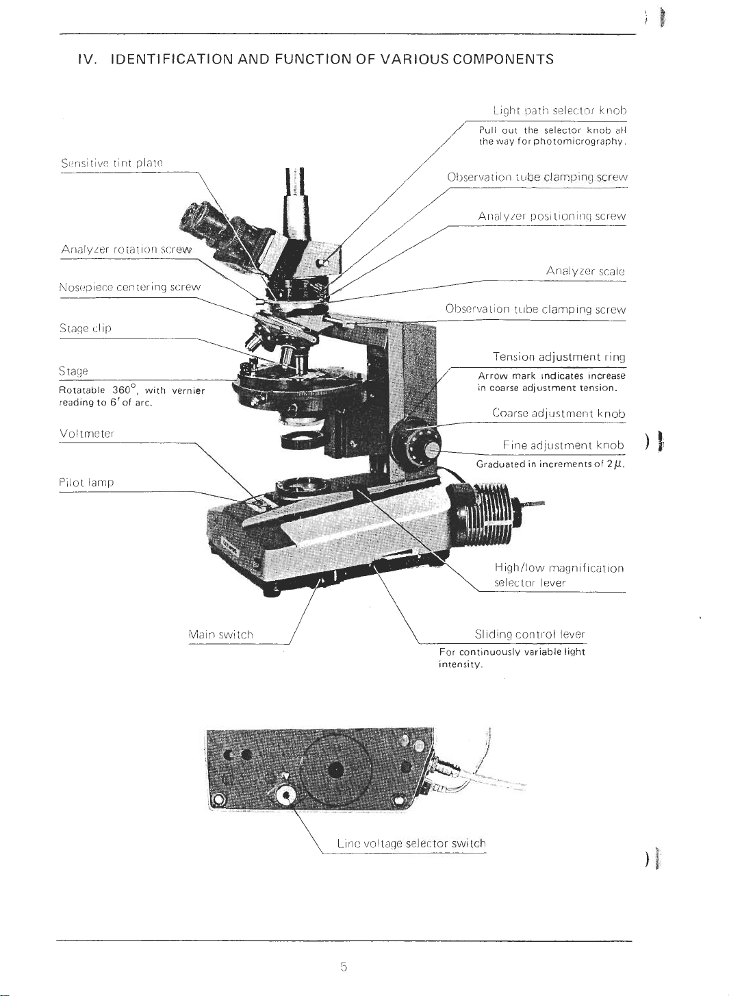
IV. IDENTIFICATION AND FUNCTION OF VARIOUS COMPONENTS
L~ght
path
Pull out the selector knob all
/
the way for photomicrography.
Tension adjustment ring
Arrow mark ~ndicates Increase
in coarse adjustment tension.
selector
Analyicl- scaic
kr~ol)
;
)
Voltmeter
\
SIlcIinq cont~~ol lever
For cont~nuously variable light
intensity.
\
L~ic vol~~g~
selector
switch
Page 8

Mer.lianical tube length
adjust-
Clarnping screw for
mechanical stage
45'
click stop lever
Polarizer scale
Reading to
5'.
ngraved letters "IN" for in-
of
sertion
the light path;
removal of the Bertrand lens
from the light
Clamping screw for
uated.
Bertrand lens into
"OUT"
path.
for
stage
Filter mount
Field iris diaphragm ring
Polarirer rotation ring
Rheostat trimmer screw
screwdriver until the
with the slid~ng control lever positioned
closest to vou (low voltage).
voltmeter
Larnp house clamping screw
indicates IV,
Page 9

Automatic
Nosepiece
clamping
the cap
of
replace the defective fuse with
a
replacement fuse.
(Disconnect BEFORE RE-
PLACEMENT.)
the fuse holder, and
Page 10

Summary of Putting the Microscope in Operation
Model BHA-P
A. Match the line voltage selector switch to local mains voltage (see page
Switch on the light source.
B.
Rotate the trimmer screw until the voltmeter indicates
C.
Place a specirnen slide on the mechanical stage.
D.
Remove the Bertrand lens and analyzer from the ligh! path.
E.
10X
Coarse focc~s with the
F.
Make interpirpillary and diopter adjustments (page
G.
Center the condenser (page
H.
Center the stage (page 12).
I.
Center objectives other than
J.
Swing in the desired objective.
K.
L.
Set the condenser, analyzer and Bertrand lens correctly according to your microscopic
purpose (pages 13 and 14).
M.
Adjust illumination system.
N. Adjust light intensity.
0.
Fine focus.
objective.
10)
10X
(page 12)
10)
1V
(page
6).
9)
Adjust aperture iris diaphragm and field iris diaphragm (page
P.
(
Adjustment of illumination system
Intermediate
polarizing at-
tachment
OUT
IN
"H"
positior? for
put
~t on the wall near the microscope for
r
4X
Objective
4X
20X
and
lox,
to
to
100X
100X
aricl the
Microscopic
Orthoscopic
observation
Conoscopic
observation
For biological use ol the Moclel BHA-P, however, remove the analyzer, Bertrand lens
sensitive tint plates, and place the high/low magnification selector lever into the
tion lor
Cut
off this page at dotted line and
*
microscopic procedure.
Conder~ser
top lens
OUT
IN
20X. 40X
and
12).
I
Highllow magnification selector lever
100X
object~ves.
use
L
H
"L"
as a reminder of
and
posi-
Page 11

V.
OPERATION
1.
Electric System
1)
Adjustment of Light Intensity
The rninimum voltage required for the light source can be adjusted with the rheostat
trimmer screw at the bottorri of the microscope base in accordance with the line voltage
and frequency.
control. The
@
@
@
2)
Adjustment of Minimum Line Voltage
@
(3
A
silicon controlled rectifier (SCR)
SCR
has the following advantages over conventional rheostat cor-itrols.
Extremely fine adjustment of light intensity can be easily achieved
Flickering of the bulb filament is elirninated and light intensity is stabilized.
Increased life expectancy of the bulb.
Ascertain that the voltage selector switch is set to conform with the local mains
voltage. (This switch can be
voltages: 100V-110V-I 20V or 220V-240V.)
Ascertain that the sliding control lever is positioned closest to you (low voltage), and
then activate the main switch. The pilot lan-ip lights up.
turned with a coin, and can be set to the following
is
provided lor output voltage
@
If the bulb is dimnily lit, and the voltmeter indicates about IV, the secondary voltage
is correct, and you have only to push the sliding control lever forward in order to
obtain optimum light intensity.
@
If the bulb does not light or lights up brightly immediately after switching on, rotate
the rheostat trimmer screw gradually w~th a coin, until the voltmeter indicates
about 1V.
3)
Light Source
The standard light source incorporates a 30W pre-centered tungsten filament bulb,
provided with a socket for positive contact, eliminating the problems of defective
contact and over-heating.
of
When used at the rated voltage 6V. the aver-age lrfe
than 200 hours. This is,.however, greatly reduced, if the bulb is used at higher voltage; for
instance, the bulb life is reduced to 1/50 at 8V. Therefore, it is advisable to avoid
prolonged use at readings over 6V (in the red rorie).
If the light source should be used at high voltage constantly, it is reconirnended to usea
high intensity halogen bulb.
*
Do not switch the tungsten bulb on &ith the sliding control lever at high intensity posi-
tion (away from the user). It reduces bulb life.
the tungsten bulb LS30 is longer
Page 12

2.
lnterpupillary Distance and Diopter Adjustments
Insert the eyepiece v~ith cross hairs of your choice into
1)
tile right eyepiece tube, align~ng the positioning slot
and position~ng pi11
*
When the eyepiece positioning pin is inserted into the
lower slot on the tube, the cross lines in the eyepiece
coincide with the vibration direction of polarizer and
analyzer at
slot, the cross lines are at
vibration.
2)
Looking through the iight eyepiece (with cross hairs)
with your right eye, rotate the d~opter adjustment ring
@
until the cross hairs are sharpty focused. (Fig.
3)
Looking through the both eyepieces with both eyes,
adjust the interpupillary distance, sliding the knurled
dovetail slides
cintil perfect binocular vis~on is obtained.
4)
Memorize your interpupillary distance setting by means of the scale
5)
Rotate the tube length adjustment ring @ on the right eyepiece tube
interpupillary distance setting which you obtained from the scale
@
.
(Fig.
1)
0
settings. When inserted into the other
45O
to the direction of
@
of the right and left eyepiece tubes,
@
2)
@
Fig.
2
to
match your
,
))!{
6)
Look at the image through the right eyepiece with your right eyepiece v~ith your right
eye and focc~s on the specimen with the coarse and fine adjustment knobs.
7) Look at the image through the left eyepiece with yocrr left eye and rotate the tube length
@)
adjustment ring
ment knobs.
3.
Light Path Selection
The trinoc~.llar tcrbe is provided with a light path selector knob to direct the light to the
observation tube or to the phototube.
Knob position
Pushed in all the way.
Pulled out all the way.
to focus on the specimen without using the coarse and fine adjust-
Amount of light
100%
into binocc~lar tub:!
20%
into binocular tube
80%
into phototube
Application
Observation
Photomicrography
Page 13

4.
Condenser Centration
1)
Br~ng the
*
If a specimen
without
the peripheries of the specimen with the stage clips
provided to the circular stage.
Swing in the condenser top lens, and br~ng the specimen
into focus.
objective
a
mechanical stage it is recommended to hold
10X
into the light path.
is
placed on the circular rotatable stage
Stop down the field iris diaphrag~n w~tli knurled ring
A
slightly blurred image of the field diaphragm can now
be seen in the eyepiece.
4) Move the condenser up and down to locus on the image of the field diaphragm.
*
If the specimen slide is too thick, it is sometimes impossible to obtain a sharply-focused
image.
5)
While widening the diameter of the field progressively,
(3)
screws
6)
Push the analyzer @ into the light path, and make sure
that both polarizer and analyzer are set at position
to attain the "Crossed filter" position. Then loosen the
clamping screw
to bring the diaphragm iniage Into the center of view. (Fig.
(2)
(Fig.
3)
of the condenser.
(Fig,
4)
a.
"0"
Flg.
3
iise
the condenser centering
3)
7)
Remove
transparent area comes into the light path. Keeping the
polarizer at the
tion ring @ until the optimum extinction is obtained,
then clamp the ring. (Fig.
the speclmen o~~t of the light path so that a
"0"
position, rotate the polarirer rota-
4)
.
I++-&:
/--:,
Fig.
.,
4
.
,
,--
j,i
Page 14

5.
Centering the Stage
I)
Looking througlk llic eyeplece ancl objective
In
you like,
hairs of the eyepiece.
the specimen irnage and coincidii thrs point with
10X,
cleter~nine solme particular point, as
thc
center of the cross
2)
Rotating the stage, coincide the center of
the rotation oi the specimen's point g~ith
the center of the cross hairs by means of
two centering screws
stage. (Fig.
*
Repeat this procedure until the centration
6.
Centering the Objectives
This centration
the pre-centered objective
1)
Connect a centering knob 9 to each centering screw
the circular rotatable stage. (Fig.
21
By means
centers of the cross hairs and the rotation of the
specimen.
3)
After complete centration, remove the centering knobs.
7.
Use of Iris Diaphragms
1
)
Aperture iris diaphragm
Adjust the opening of the aperture iris diaphragm
according to the various conditions scrch as the numerical aperture of the objective, irnage contrast, depth of
focus, and flatness of field. Generally it is often preferable to stop do\nln the aperture iris diaphragm to the
or
80%
After the eyepiece is removed from the observation
tube, if necessary, look through the observation tube
and check the opening of the aperture diaphragm at the
objective pupil.
51
is
secured.
is
of
these two centering screws, coincide the
of the N.A. of the objective.
[I?
provided on tlie
necessary to all the
POlOX.
6)
PO
objectives except
of
70%
11111
I--
>--
-
--
Fig.
6
-
2)
Field iris diaphragm
The field [!-is diaphl-agm controls the diarnetellneri s~~rface and thus increases irriage definition.
Generally, it is prefel-able to slightly increase the diameter of the field iris diaphragm until
it is just outside the field of view.
!
of
tlie ray bcrndle ~nlpinging on the speci-
Page 15

8.
Focusing Adjcistment
1)
Tension adjustment of coarse adjustment ltnobs
A
tension adjustment ring
riqlit hand coarse adjustment
terisior) of the coarse adjustment is freely adjustable
eittier- heavy oi liclti t movement rfependincl or1 opcrator
01-eference.
Iiowever, do not loosen thc: tension adjustrnent rlny too
rnoch, because the stage clrops, or the
knobs sl111 eas~ly. Fig.
*
Be careful not to rotate the right and left coarse adjustment knobs
2)
Pre-focusing lever
This levci.
accomplished. It prevents further ~ipward travel of the
stage by nienns of the coarse adjustrnent knobs, and
autoniatically provides a liiniting stop if the stage is
lowered and then raised agaln. (Fig.
9.
Orthoscopic Observation
1)
Swing out tile top eris
In
principle, polarizided light enters the light path, parallel to the optical axis, to enable
observalion of the optical characler~st~cs of the specirnen. However, this method will
darken the field of view and lower the resolving power
fore, swing out the top lens of the condenser, using only the lower aperture of the lower
condenser lens.
in
the opposite directions sim~iltaneously.
3)
is locked after coarse focirs has been
of
IS
provided nc!xt to the
knob.
With this clevice the
8)
the condensel
fine
adjustrncnt
lo^.
7
FI~.
8
of
the objective extremely. There-
2)
Insert the analy~er into the light path, and attain the crossed filter position with analyzer
0
and polari7er at
direction, and the analyzer vibration in the east-west d~rection. To open the filter position, pull out the analyrer rotation screw.
3)
Rotatc the stage until the extinction of the image is
attaned, and n)ove tlic
the operator.
Frorn this position, it is easy to rotate the stage in
45'
Increments without having to ircfer to
scale, and the stage clicks at the clla~onal position, at
\vliicii position. the retardation angle
relcase the
lever.
45O
setting.
(Fig,
cl~ck stops, push back the
At this pos~tori, the polari~er vibra~i
45'
click stop lever $ toward
9)
the
angular
is
measured. To
45"
click slop
I
In
is in the north-south
Fig.
9
Page 16

4)
Insel-t the quarter \Nave pltite or sensitive tint plate into tlie slot in
l)oIarr?in(j lul~e,
*
A
Berek compensator
is
optionally available to measure the birefringence of a specimen.
:he
intcrmccliato
Sensit~ve tint plate Quarter
10.
Conoscopic Observation
1)
Swing in the top lens of the condenser, and illornrnate the specimen with no need to
immerse between the condenser and specimen slicle,
2)
Bring the specimen into foccrs, rotate the Bertrand lens tcrrrent ring into the
3)
Focus on the interference
20X
ro
100X.
The pinhole cap provided may be ~~sed in place of the eyepiece to directly view the
interference figure mentioned above. In this case, the Bertrdncl lens is disengaged.
11.
Photomicrography
1)
Photomicrographic equipment
Photomicrography i~ith the h4odel
the photomicrograpliic system camera, exposure meter, photo eyepiece, etc. Read the
lnsiruction manuals for each equipment, and follow the steps below:
a
It
is
recommended to use a low power photo eyepiece
@
Photor~iicrographic magnification 1s same as witl-1 the standard optrcal tube length,
although the optical tube length for- this use
polariilng tube.
(I~LI~C
wave
plate
formed at the back focal plane of the objective frorn
BHA-P
requires photomicrographic equipment such as
is
prolonged because of the
Berek
FK2.5X.
compensator
IN
position.
intermediate
0.
)
I
Page 17

VII.
OPTICAL
DATA
[
WFlOX
-
-
PO20X
0.40
1.58
3
8.1
0.84
1 OOX
15.56
1.05
200X
9.19
0.9
P040X
0.65
1
0.6
4.33
0.52
(Spring
loaded)
200X
4.99
0.53
400X
3.03
0.45
is
used at the full
Objective Magnification
K5X
r::ber
11 81
-
2 1
)
)ecW(mm)-
N.A.
W.D.
imml
Focal length
Resolving power
Total magnification
Focal depth
f
otal magnification
Focal depth
Field of view (mm)
(mrn)
--
(
I*)
(
,U
Immersion objective. Resolving power
P04X
0.1 0
18.77
28.45
(
P
3.4
)
20X
300.0
5.25
40X
172.5
4.5
POlOX
0.25
6.78
16.08
'
1.3
50X
48.0
2.1
1 OOX
27.60
1.8
is
obtained when the objective
aperture diaphragm.
The eyepieces
K5X
and WFlOX incorporate a sliding eye shield. This eye shield can be
pulled out to prevent glare and loss of contrast caused by arnbient light hitting the eye lens.
0
W.D.
(Working distance):
The distance between the specimen orcover- glass and the nearest point of the objective.
A
POlOOX
1.30
0.1
1.81
.-
0.26
(Spring
loaded)
500X
1.05
--
0.21
1,OOOX
0.66
0.18
1
9
0
N.A. (Numerical aperture):
a
The n~~merical aperture represents
the relative aperture (f-number) of a camera lens.
perforrnance number whlch cocrld he compared to
N.A. values can be usecl for directly
comparing the resolving powers of all types of objectives. The larger
resolving power.
0
Resolving power:
a
The abllily of
lens to register small details. The resolving power of a lens
its ability to separate two points.
0
Focal depth:
The
disrance between the upper and lower limits of sharpness in the image formed by an
optical system.
0
Field number:
A
number that repl-esents the diameter in
formed bv the lens
0
Field of view diameter: the actual six of the field
~ri
front of it.
t
lnln
of the image of
of
view in mnl.
N.A..
the higher the
IS
measured by
the
field diapliragnl that is
Page 18

VI II. TROUBLESHOOTING
I
I
1.
'
(a) With the illuminator The highllow magnification selector Place the lever in correct position.
I
Troubles
Optical System
switched on, the field of lever is not correctly positioned.
view cannot be seen.
The condenser is lowered exces- Raise the condenser to the upper
Causes
I
Remedies
i-I
(b)The field of view is cut off
or illuminated irregularly.
Analyzer and polarizer are in the
"crossed filter" position
The light path selector lever is stopped midway.
The highllow magnification selector
lever is not correctly positioned.
The auxiliary lens is not correctly
attached.
The nosepiece is not click stopped. Slightly rotate the nosepiece until
The nosepiece is not correctly at- Insert the sliding dovetail mount
tached to the stand.
("0:O").
Sei them at the position
"90:O".
Push the lever all the way.
Place the lever all the way.
Correct the lens position.
1
clicks into position.
lnto the stand all the way, until it
stops, then lock.
"0:90"
-
I
or
(c) Dust or dirt
the field of view.
is
visible in
The condenser is not correctly
mounted on the ring mount.
The sensitive tint plate is stopped
midway.
In case of orthoscopic observation,
the condenser top lens stays in the
light path or stops midway.
is
The field iris diaphragm
down excessive1 y.
The lamp is not correctly attached.
Dust or dirt on the glass surface at
the light exit on the base.
Dust on condeqser top lens.
Dirty specimens.
I
Dust on eyepiece.
stopped
Re-insert the condenser all the way.
Push the plate all the way until
clicks.
Swing it out of the light path.
Open the diaphragm fully.
Re-insert the lamp correctly.
Clean off the dust or dirt.
I
it
Page 19

Troubles
(cl
)Excessive irnage contrast.
The condenser
sivel y.
Causes
IS
lowered exces-
Remedies
Raise the condenser.
The aperture irls diaphragm is stoppet1 down excessive1
The auxiliary lens is not mounted.
The high/low magnification selector
lever is not correctly positioned.
(e) Pesolution problems:
0
1
fiage is not sharp.
0
lrscrfficient contrast.
lrnage
details
tron.
lack
defini-
D
The nosepiece
tached.
The objective is not correctly positioned in the light path.
Dirt on objective front lens.
The immersion objective
without immersion oil.
Birbbles in the
The Olympcrs designted oil
used.
Dirty specimen.
Dirt on condenser lens.
The specirnen is not properly il-
luminated.
y.
is
not correctly at-
immersion
oil.
is
IS
used
not
Operi tile diaphragm.
Mount the auxiliary lens.
Place the lever in correct position.
Insert the sliding dovetail mount all
the way, until it stops, then lock.
Slightly rotate the nosepiece until
it clicks into
Clean the objective.
Apply immersion oil.
Remove bubbles.
Use the designated oil.
Clean.
Adjust the illumination.
position.
(f) The field of view
ly out of focus.
(g) The image goes out
focus cccentr~cally.
is
partial-
The nosepiece is not correctly attached.
IS
The objective
tioned in the light path.
The specimen is not correctly positioned on the stage.
The nosepiece is not correctly at-
of
tached.
The objective
tioned in the light path.
The condenser
The auxiliary lens is not correctly
rnoc~n tecl.
The higti/low rnagnlfication selector
lever is stopped midway.
not correctly posi-
is
not correctly posi-
is
out of center.
Insert the sliding dovetail mount
all
into the stand
lock.
Slightly rotate the nosepiece until
it clicks into position.
Place the specirnen on the stage and
secure it with the specimen clips.
Insert the sliding dovetail mount all
the way, until it stops, then lock.
Slightly rotate the nosepiece until
it clicks inlo posilion.
Cenler the condenser.
Mocrnt the lens correctly.
Place the lever in correct position.
the way, then
Page 20

Troubles
-
--
!h)Wlien objectives are
changed, they are not parfocal.
-
-
-
- - -
Causes
.-
The mechanical tube length is not
correctly adjusted.
Remedies
Adjiist with the tube length adjustment rings on the observation tube.
(i) Light intensity does no1
increase although the volt-
age is raised.
(1)
The condenser does not
come to the correct position for optimum extinction.
(k)No conoscopic image can
be seen.
(I) The crossed filter position
is
not atte~ned.
2.
Electric System
la)The illuminator
is
too
bright (or too dark).
The condenser is not correctly centered.
is
The condenser
lowered exces-
sively.
The observation tube and condens-
er are not correctly mounted.
The condenser top lens is not in
the light path.
The analyzer is out of the light
I
path.
The rheostat trimmer screw is not
matched to the mains voltage.
-
The mains voltage is too high (or
too low).
The rheostat trimmer screw is not
correctly adjusted.
Center the condenser.
Raise the condenser.
Re-mo~lnt them correctly.
Swing it in.
Push it in.
Adjust the trimmer screw to match.-B
the mains voltage.
Adjust the mains voltage with
a
variable voltage transformer.
Adjust the trimmer screw until the
1
voltmeter indicates
V.
(b)Output voltage for the il-
luminator cannot be regulated.
The voltage selector switch is not
matched to the mains voltage.
The mains voltage is too low or too
high.
(c) The light flickers and the
intensity is unstable.
The mains voltage is unstable.
The filament of the bulb is likely
to bi.rrn out.
Loose electrical con1 ~ection.
(d)Fuse burns out too often.
The fuse
The voltage selector switch is not
matched to the mains voltage.
(e) The pilot I;~mp l~glits b~~t
the bull2
docs
not.
The bulb
Loose electrical connection.
IS
not a standard fuse.
IS
burned out.
Adjust the mains voltage selector
switch to the mains voltage.
Adjust the mains voltage with
variable voltage transformer.
Use a variable voltage transformer.
Replace the bulb.
Secure the connection.
Use a standard fuse.
Match the swilch to the mains
voltage.
Replace the b1.115,
Secure the connection.
a
Page 21

Troubles
(f)
Reduced bulb life.
Causes
The voltage selector switch is not
matched to the mains voltage.
Remedies
.
Match the selector switch to the
mains voltage.
3.
Focusing
(a) Coarse adjustment is too
tight.
(b)The stage drops and the
specimen goes out of focus.
(c)
The stage cannot be raised
to
the upper limit.
(d)The stage cannot be lower-
ed
to the lower limit of
the working range.
The bulb is not a standard bulb.
Mains voltage is too high.
Tension adjustment ring is tightened too much.
The user is trying to raise the stage
passing over the upper focusing
limit imposed by the engaged prefocusing lever.
The tension adjustment ring is too
loose.
Automatic pre-focusing lever is engaged in lower than focusing position.
The condenser mount is lowered
too much.
Use a standard bulb.
Use the tungsten bulb under
well as possible, or use a high
intensity bulb, such as a halogen
bulb.
Loosen the tension adjustment ring
properly.
Unlock the pre-focusing lever.
Tighten the ring properly.
Unlock the pre-focusing lever.
Raise the condenser mount.
6V
as
(e)The objective front lens
hits against the specimen,
4.
Observation Tube
(a) l ncomplete binocular vi-
sion.
5.
Stage
(a)
The image easily goes out
of focus when you touch
-B
the stage.
(b)The specimen stops mid-
way on the east-west trav-
erse.
The specimen is mounted on the
stage upside down.
lnterpupillary distance is not correctly adjusted.
Diopter adjustment is incomplete.
Right and left eyepieces are not
matched.
The user is unaccustomed with a
binocular vision.
The stage is not correctly clamped.
The specimen is not correctly posi-
tioned on the stage.
Reverse the specimen.
Correct the interpupillary distance
Complete the diopter adjustment.
Use a pair of matched eyepieces.
Prior to looking at the image of the
specimen, try to look the entire
field of view, or look at a far away
object before resuming microscopic
observation.
Clamp the stage securely.
Adjust the specimen position.
 Loading...