

Scannedforpersonal,non‐businessuseonly
September20,2018
OLYMPUS
RESEARCH
BH2
MICROSCOPES
SERIES
TROUBLESHOOTING
&
ADJUSTMENT
FOR
B2-BDT,
MANUAL
ELECTRICAL BASE
B2-BDS-2,
B2-BDS-3
OLYMPUS
INTRODUCTION
Three
for
• B2-BDT
•
The
Using
types
the
B2-BDS-2
difference
This
•
Troubleshooting
•
Troubleshooting
•
Adjustment
BH2
is
of
electrical
Series.
used
and
B2-BDS-3
between
Manual"
for
Refer
commonly
B2-BDS-2
in
the
for
for
B2-BDS-2
base,
for
are
manual.
B2-BDT
B2-BDS-2
B2-BDT/B2-BDS-2/B2-BDS-3
to
the
BHT,
used
and
GENERAL
..........................
.............................
manuals
BHTU
commonly
B2-BDS-3
CONTENTS
and
for
for
each
BHTM.
BHS,
is
model.
BHSU
described
are
and
in
Section
Section
Section
available
BHSP.
"Hints
for
A
B
C
•
Troubleshooting
•
Adjustment
for
for
B2-BDS-3
B2-BDS-3
.............•..........
.............................
Section
Section
D
E
1.
2.
3.
4.
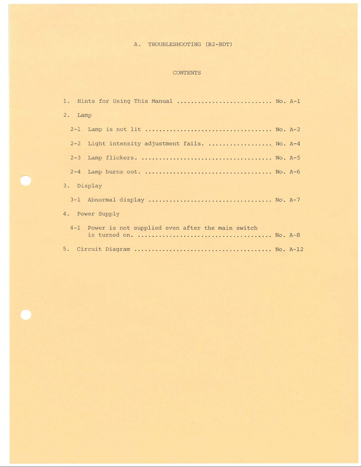
Hints
Lamp
2-1
2-2
2-3
2-4
Display
3-1
Power
for
Lamp
Light
Lamp
Lamp
Abnormal
is
flickers.
burns
Supply
A.
TROUBLESHOOTING
Using
intensity
This
Manual
not
lit
adjustment
.
....................................
out. . ...................................
display
...................................
(B2-BDT)
CONTENTS
.........•.................
fails.
.
.................
.
No.
No.
No.
No.
No.
No.
A-1
A-2
A-4
A-5
A-6
A-7
5.
4-1
Circuit
Power
is
turned
is
not
on.
Diagram
supplied
. . . . . . . . . . . . . . . . . . . . . . . . . . . . . . . . . . . . . .
.......................................
even
after
the
main
switch
No.
No.
A-8
A-12
l.
Hints
This
arrow
The
of
for
Using
manual
mark
numbers
connector
to
is
and
and
A.
TROUBLESHOOTING
This
Manual
written
find
symbols
pin.
in
out a defective
like
the
(B2-BDT)
flowchart
part.
[I] ,
~
format.
indicate
Follow
the
the
numbers
No.
A-1
"Refer
pin l and
oscilloscope".
* "
GND
HOT
The
the
The
the
to
0-
[I]
+A
reference
+ A
line
symbols
same i tern"
symbols
check
the
waveform
GND
to
"
means
to
like
.
@
methods
of
pin 2 when
"Connect
voltage,
apply
and
@
@
a
and
@
and
JJ
HOT
OV,
supply
@
mean
QV
using
to
in
voltage.
mean
"Proceed
given
~
"
means
a
multimeter
pin 2 and
an
electronic
"Jump
the
in
to
the
"Connect
GND
@
work
same
HOT
or
an
to
pin
circuit.
and
@
according
item".
to
l".
in
to
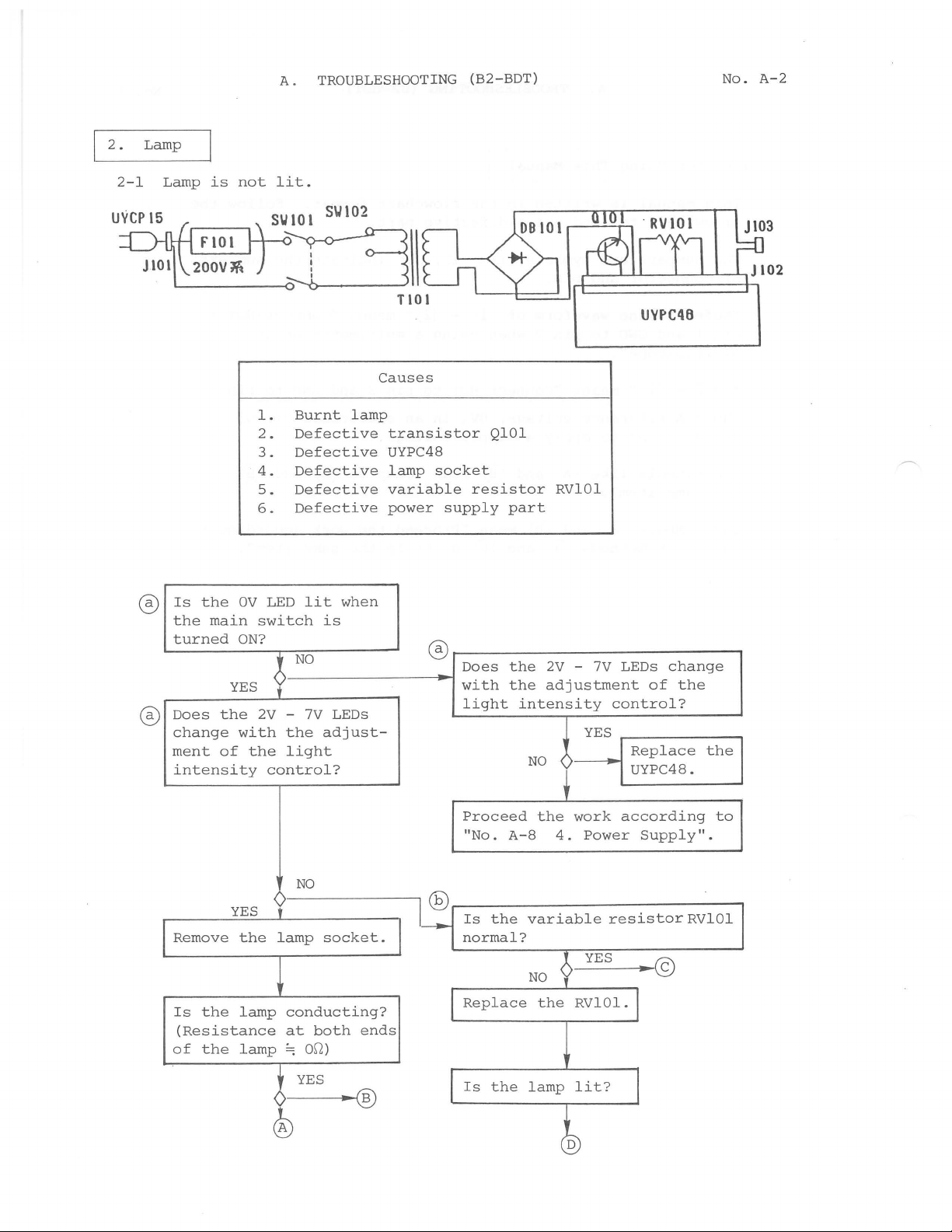
2.
2-l
Lamp
Lamp
is
not
A.
TROUBLESHOOTING
lit.
Causes
(B2-BDT)
UVPC48
No.
A-2
0
0
Is
the
the
main
turned
Does
change
ment
intensity
the
of
OV
ON?
YES
with
the
Burnt
l.
2.
Defective
Defective
3.
4.
Defective
Defective
5.
Defective
6.
LED
lit
switch
NO
2V -7V
the
light
control?
lamp
when
lS
LEDs
adjust-
transistor
UYPC48
lamp
variable
power
socket
0
resistor
supply
Does
with
light
Proceed
"No.
QlOl
part
the
the
A-8
RVlOl
2V
adjustment
intensity
NO
y
the
'
4.
7V
-
YES
work
Power
LEDs
of
control?
Replace
UYPC48.
according
Supply".
change
the
the
to
YES
Remove
Is
(Resistance
of
the
the
the
lamp
lamp
NO
9
lamp
f
0
socket.
conducting?
at
both
~
om
YES
®
ends
~®
@
Is
the
normal?
Replace
Is
the
variable
NO
the
RVlOl.l
lamp
lit?
~
YES
resistor
~©
I
RVlOl
A.
®
TROUBLESHOOTING
(B2-BDT)
No.
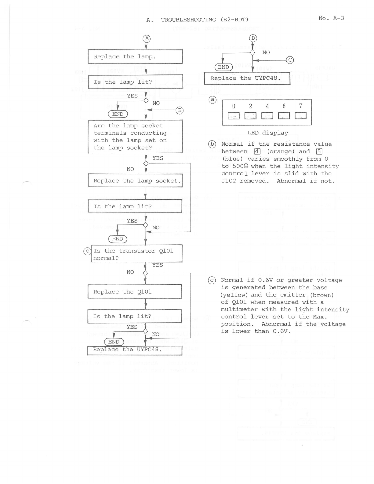
A-3
Replace
Is
Are
terminals
wi
th
the
Rep
Is
the
the
the
lamp
lace
the
the
lamp
YES
lamp
conduc
lamp
socket?
NO
the
lamp
YES f
~f-C--
lamp.
lit
?
NO
+-----!B
socket
ting
set
on
YES
lamp
socket.
lit?
N_o
__
Replace
@,,
Normal
between
to
control
Jl02
_
the
UYPC48.
0 2 4 6 7
__
ODD
(blue)
500~
removed.
LED
if
the
@]
varies
when
lever
DD
displa
resistan
(orange)
smoothly from
the
is
Abnormal
y
light
slid
ce
and
with
value
~
intensit
the
if
not.
0
y
the
norma
Replace
Is
the
transistor
l?
the
lamp
NO
QlOl
lit?
YES
QlOl
~
Normal
is
generated
(yellow)
o f
QlOl
multimeter
control
position.
is
lower
if
and
when
lever
than
0.6V
or
between
the
measured
with
set
Abnormal
0.6V
greater
the
emitter
with
the
light
to the Max.
if
the
.
voltage
base
(brown)
a
intensit
voltage
y
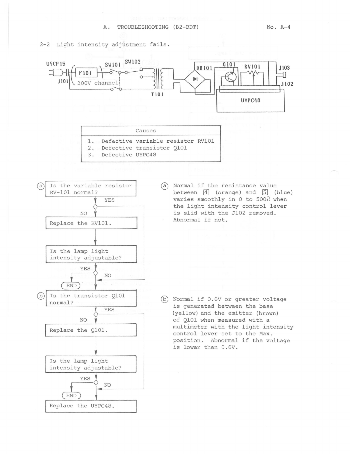
2-2
Light
intensity
A.
TROUBLESHOOTING
adjustment
fails.
(B2-BDT)
No.
A-4
®
Is
the
RV-101
Replace
L_
______
variable
normal?
NO
the
SUlOl
SU102
c_h_a_n_~
TlOl
UVPC4B
Causes
l.
2.
3.
RVlOl.
Defective
Defective
Defective
resistor
YES
variable
transistor
UYPC48
resistor
®
QlOl
Normal
between
varies
the
light
is
slid
Abnormal
RVlOl
if
the
0J
(orange)
smoothly
intensity
with
if
not.
resistance
in 0 to
the
Jl02
and
500~
control
removed.
value
~
(blue)
when
lever
Is
intensity
Is
normal?
Replace
I
Is
intensity
Replace
the
lamp
adjustable?
YES
j_
(END
the
transistor
NO
the
the
lamp
adjustable?
YES)
~)
the
light
t
NO
I
l
YES
1
QlOl.
light
NO
UYPC48.
QlOl
I
@
Normal
is
(yellow)
of
multimeter
control
position.
is
if
generated
QlOl
lower
0.6V
and
when
with
lever
Abnormal
than
or
between
the
emitter
measured
the
set
0.6V.
greater
the
with
light
to
the
if
voltage
base
(brown)
intensity
Max.
the
a
voltage
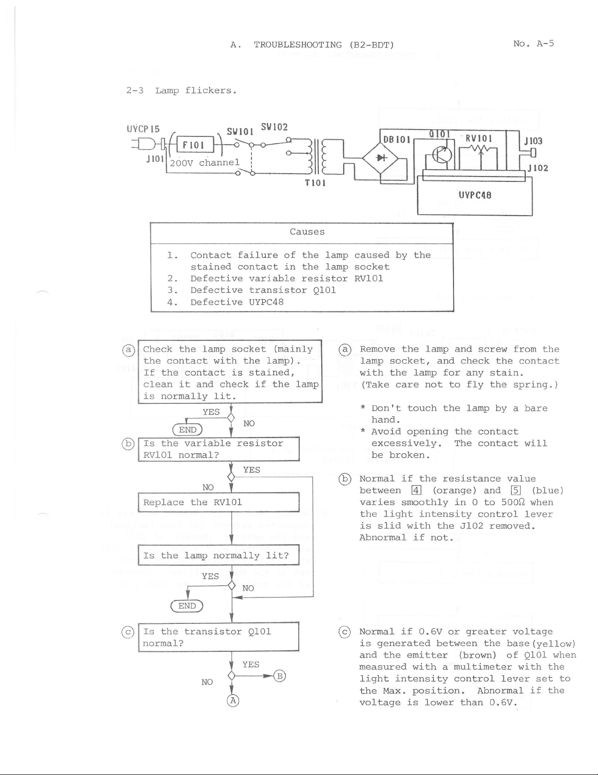
2-3
Lamp
flickers.
A.
TROUBLESHOOTING
Causes
(B2-BDT)
UVPC48
No.
A-5
®
@
l.
2.
3.
4.
Check
the
contact
If
the
clean
is
normally
Is
the
RVlOl
Replace
Contact
stained
Defective
Defective
Defective
the
lamp
contact
it
and
~YES
variable
normal?
NO
the
socket
with
is
check
lit.
i
6
RVlOl
failure
contact
variable
transistor
UYPC48
the
stained,
if
NO
resistor
YES
'
of
in
(mainly
lamp).
the
the
the
resistor
QlOl
lamp
I
J
lamp
lamp
®
caused
socket
RVlOl
Remove
lamp
with
(Take
*
Don't
hand.
*
Avoid
excessively.
be
Normal
between
varies
the light
is
slid
Abnormal
by
the
the
socket,
the
lamp
care
touch
opening
broken
if
@]
smoothly
with
if
lamp
and
for
not
to
the
.
the
resistance
(orange)
intensity
the
not.
and
screw
check
any
fly
lamp
the
contact
The
contact
and
in 0 to
control
Jl02
from
the
contact
stain.
the
spring.)
by a bare
value
~
500~
removed.
the
will
(blue)
when
lever
@
Is
the
(§)
Is
the
normal?
lamp
normally
YES
'
transistor
NO
lit?
)
NO
QlOl
YES
....
~
®
@
Normal
is
generated
and
the
measured
light
the
Max.
voltage
if
0.6V
emitter
with
intensity
position.
is
lower
or
greater
between
(brown)
a
multimeter
control
than
voltage
the
base(yellow)
of
lever
Abnormal
0.6V.
QlOl
with
if
set
when
the
to
the
A.
TROUBLESHOOTING (B2-BDT)
No.
A-6
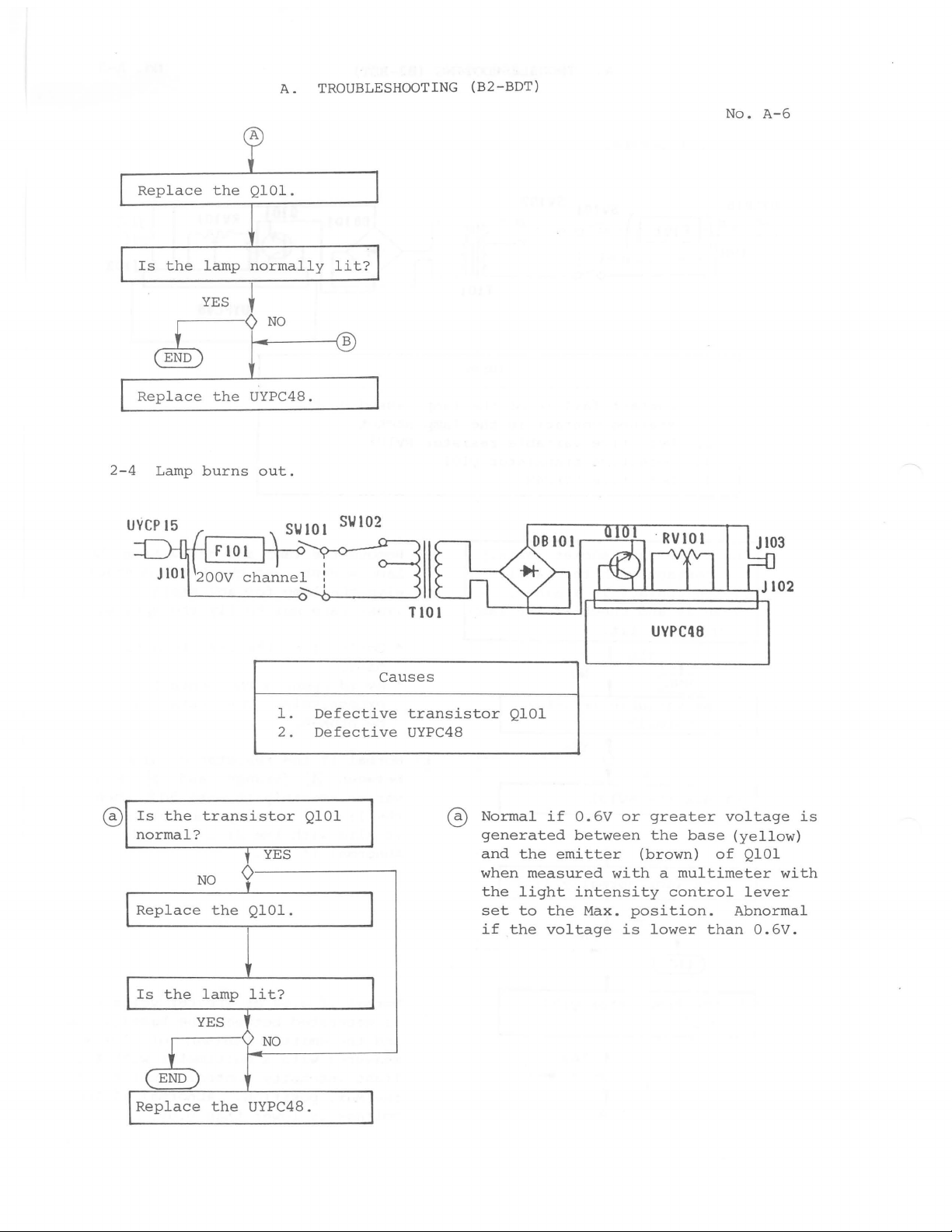
Replace
Is
the
the
lamp
YES
QlOl.
normally
•
lit?
~~N-0-----1B
2-4
Replace
Lamp
the
UYPC48.
burns
F101
out.
S\J
~
101
channe~
S\J
102
T101
UVPC4B
@
Is
normal?
I
Replace
I
Is
I
Replace
the
transistor
NO
the
the
lamp
YES
~NO
the
l.
Defective
2.
Defective
QlOl
l
YES
0---------,
t
QlOl.
lit?
-t
UYPC48. J
Causes
I
transistor
UYPC48
G0
QlOl
Normal
generated
and
the
when
the
set
if
measured
light
to
the
if
0.6V
between
emitter
intensity
the
Max.
voltage
or
greater
the
(brown)
with a multimeter
control
position.
is
lower
base
than
voltage
(yellow)
of
Abnormal
is
QlOl
with
lever
0.6V.
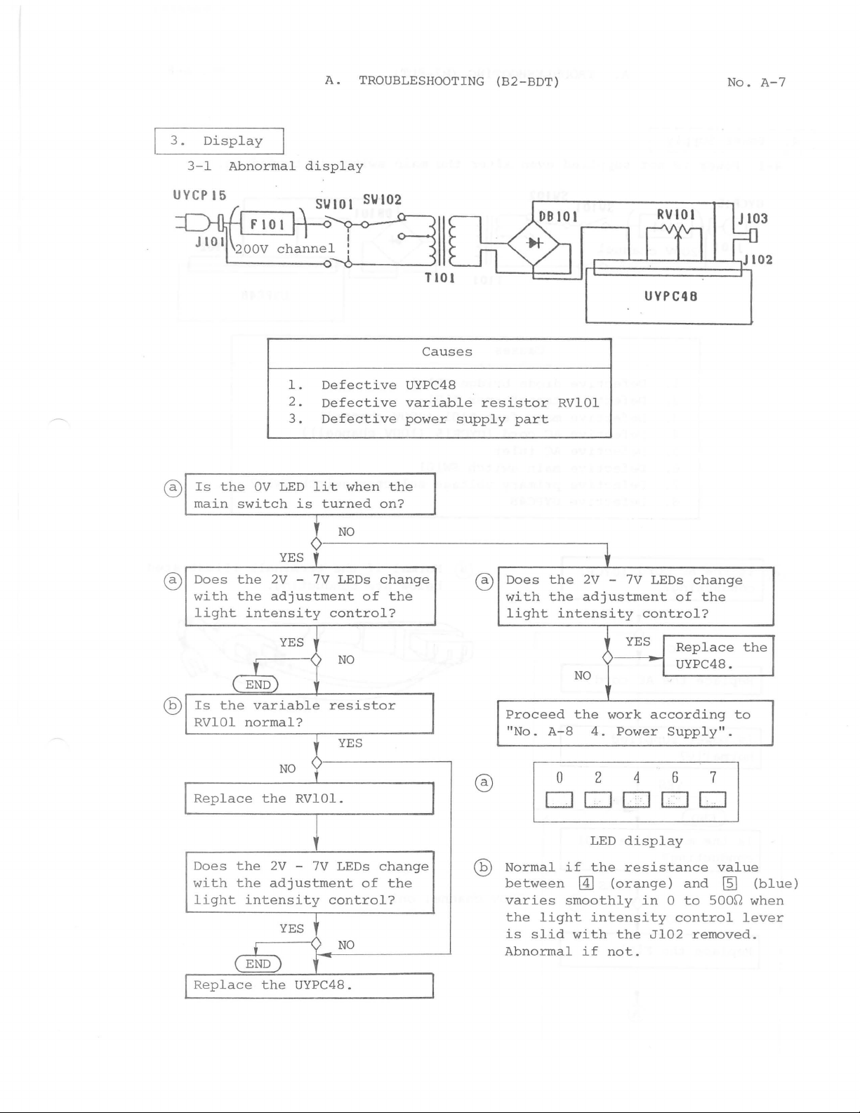
3.
3-l
UYCP15
@)
Is
main
Display
Abnormal
the
switch
OV
l.
2.
3.
LED
is
A.
display
Defective
Defective
Defective
lit
turned
TROUBLESHOOTING
Causes
UYPC48
variable
power
when
the
on?
resistor
supply
(B2-BDT)
part
RVlOl
UYPC48
No.
A-7
®
®
0
YES
Does
with
light
the
2V
the
adjust
intensity
- 7 V LEDs
YES
~
Is
the
variable
RVlOl
Replace
Does
with
light
normal?
NO
the
RVlOl.
the
2V -7V
the
adjustment
intensity
YES
~r~-N_O
'
ment
control?
resistor
?
control?
f
NO
NO
YES
of
change
the
®
®
Does
with
light
Proceed
"No.
the
2V
-
the
adjustment
intensity
~
NO
work
the
A-8
4.
0 2 4 6 7
DDDDD
LED
LEDs
change
of
the
________
~
Normal
between
varies
the
light
is
slid
Abnormal
if
the
@]
(orange)
smoothly
intensity
with
if
not.
7V
LEDs
control?
YES
according
Power
display
resistance
in 0 to
the
Jl02
change
of
the
Replace
UYPC48.
Supply".
and
500~
control
removed.
to
value
~
lever
the
(blue)
when
Replace
the
UYPC48.
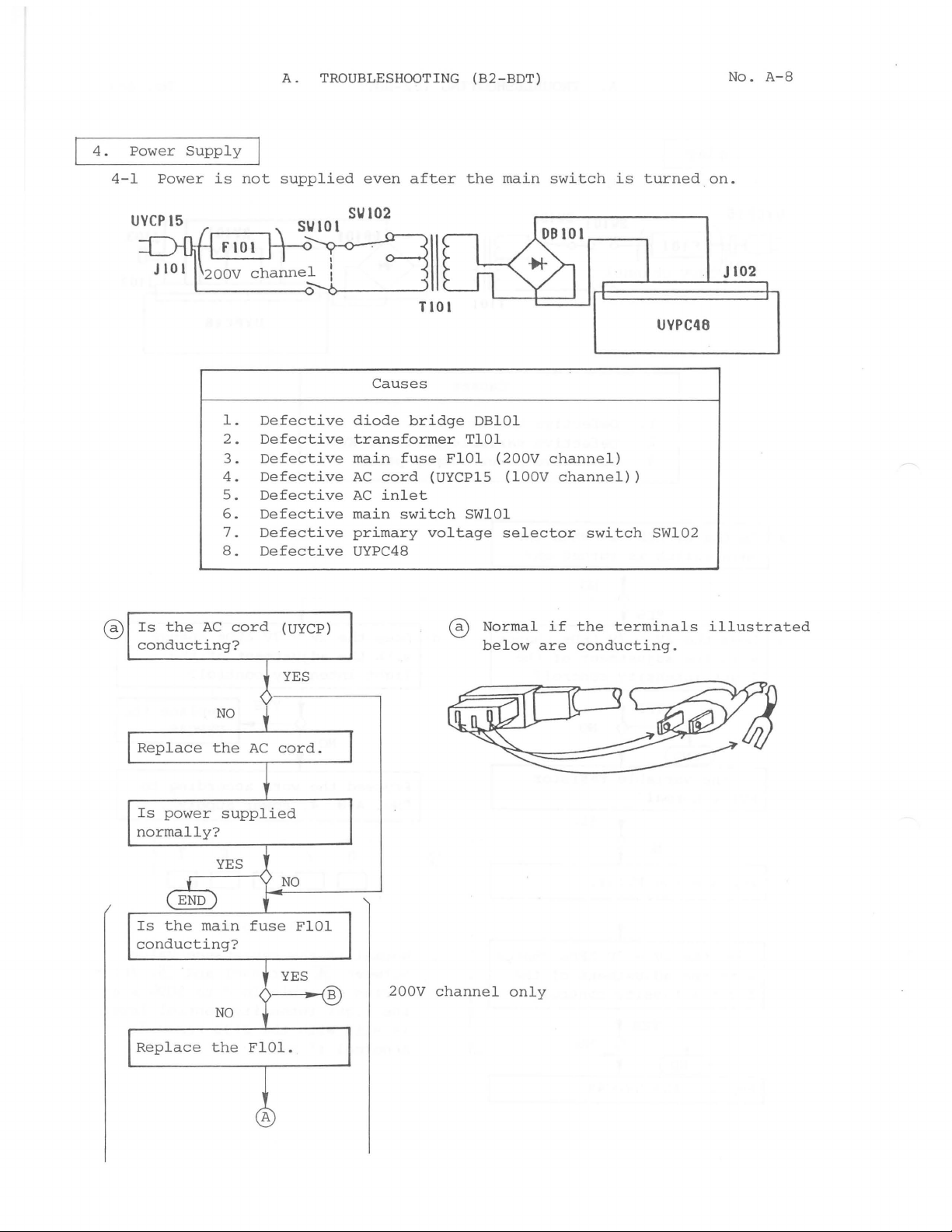
4.
4-1
Power
Power
Supply
is
not
A.
TROUBLESHOOTING
supplied
even
after
(B2-BDT)
the
main
switch
is
turned
on.
No.
A-8
UVCP15
®
Is
conducting?
the
AC
l.
2.
3.
4.
5.
6.
7.
8.
cord
Defective
Defective
Defective
Defective
Defective
Defective
Defective
Defective
(UYCP)
SIJ102
Causes
diode
transformer
main
AC
AC
main
primary
UYPC48
bridge
fuse
cord
inlet
switch
DBlOl
TlOl
FlOl
(UYCP15
SWlOl
voltage
®
(200V
(lOOV
selector
Normal
below
channel)
channel))
if
the
are
conducting.
switch
terminals
JI02
UVPC48
SW102
illustrated
Replace
Is
power
normally?
Is
the
main
conducting?
Replace
NO
the
supplied
YES
NO
the
fuse
NO
FlOl
200V
channel
only
Is
power
supplied
A.
TROUBLESHOOTING
normally?
(B2-BDT)
No.
A-9
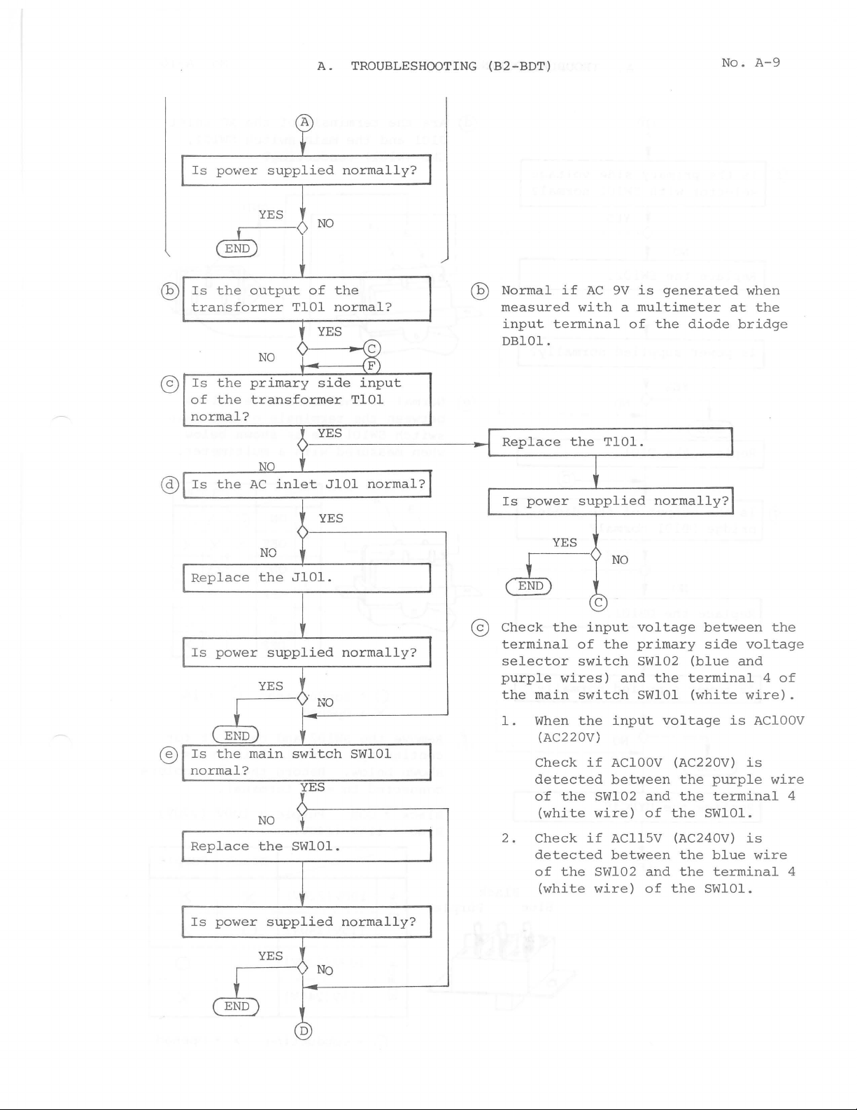
@)
Is
transformer
Is
@)
of
normal?
Is
@
Replace
YES
~
the
output
NO
the
primary
the
transformer
NO
the
AC
NO
the
TlOl
9
<
inlet
<
JlOl
NO
of
YES
side
YES
YES
the
normal?
~
input
TlOl
JlOl
.
normal?
QV
Normal
measured
input
DBlOl
I
Replace I the
I
Is
~
terminal
.
power
YES
if
AC
9V
is
generated
with a multimeter
of
the
TlOl.
supplied
•
NO
normally?j
c
diode
when
at
bridge
I
the
®
Is
power
supplied
YES
t~O
ubo
Is
the
main
normal?
I
Replace
l
Is
power
~~>.N_o
switch
NO
the
SWlOl.
supplied
YES
YES
D
normally?
SWlOl
normally?
____________
I
I
~
@
Check
terminal
selector
purple
the
main
When
1.
(AC220V)
Check
detected
of
(white
2.
Check
detected
of
(white
the
wires)
the
the
input
of
switch
switch
the
if
wire)
if
SW102
wire)
voltage
the
primary
SW102
and
the
SWlOl
input
AClOOV
between
SW102
and
of
AC115V (AC240V)
between
and
of
bet
sid
(blue
termi
(whit
voltage
(AC220V)
the
the
the
SWlOl.
the
the
the
SWlOl.
ween
e
voltage
and
nal 4 of
e
wire).
lS
AClOOV
is
u p
rple
terminal
is
blue
wire
terminal
the
wire
4
4
QD
I
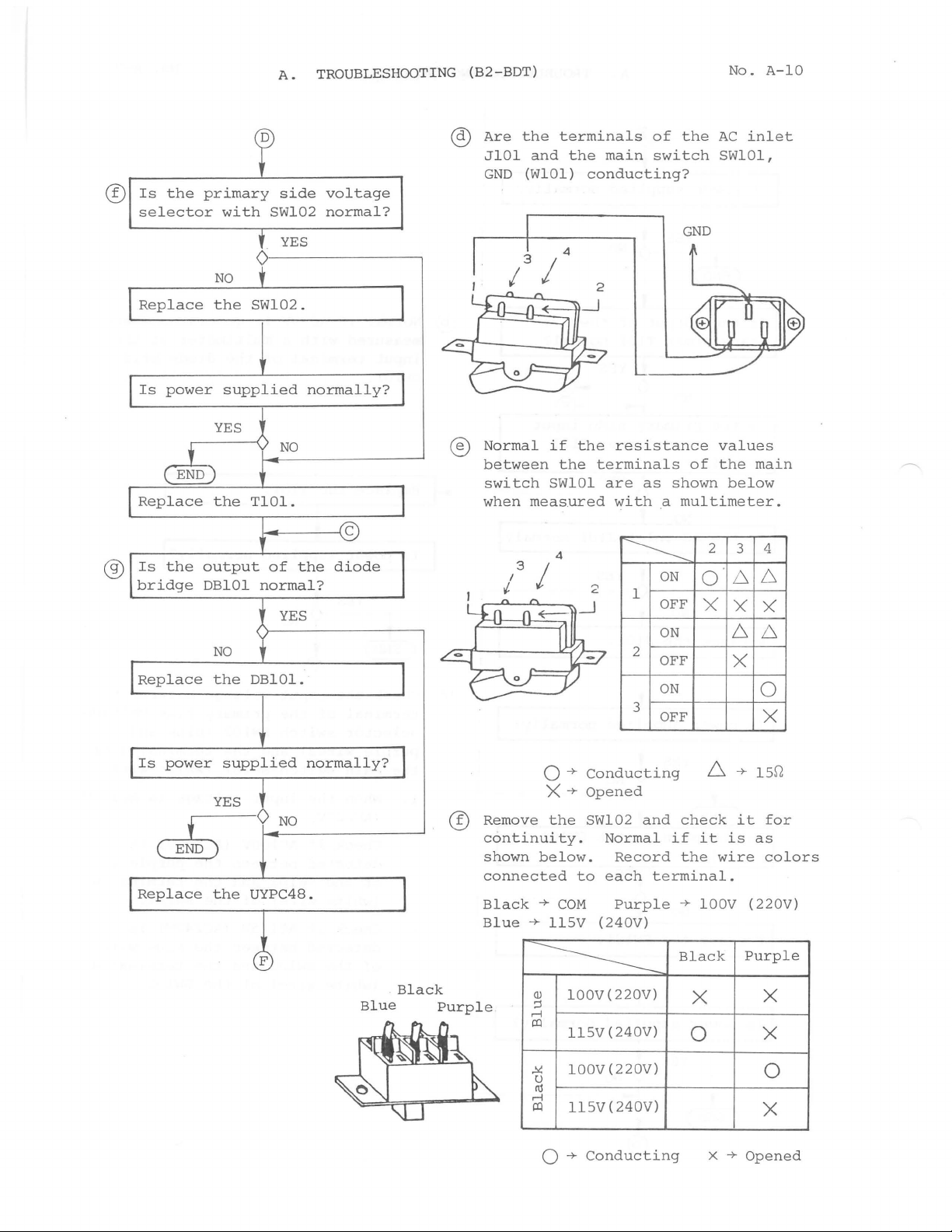
A.
TROUBLESHOOTING
Is
the
selector
primary
with
side
SW102
f
YES
voltage
normal?
0---------,
NO
t
Replace
Is
power
the
SW102.
supplied
normally?
~-NO-
(B2-BDT)
@
Are
JlOl
GND
®
Normal
between
switch
when
the
terminals
and
the
(WlOl)
4
I
if
the
SWlOl
measured
main
conducting?
the
resistance
terminals
are
with
of
switch
as
a
shown
No.
the
AC
inlet
SWlOl,
GND
values
of
the
below
multimeter.
A-10
main
®
Is
the
bridge
Replace
Is
power
(
END)
Replace
output
DBlOl
NO
the
supplied
YES
•
.----0
the
of
the
normal?
YES
DBlOl.
NO
UYPC48.
diode
normally?
Blue
Black
Q)
Purple
3
I
I
'
0-+
X+
Remove
continuity.
shown
connected
Black
Blue
below.
-+
-+
-----------
Q)
;::1
rl
a:!
4
,..,
c.
Conducting
Opened
the
SW102
Normal
to
each
COM
llSV
(240V)
lOOV(220V)
llSV
(240V)
~
l
2
3
and
Record
terminal.
Purple
ON
OFF
ON
OFF
ON
OFF
check
if
the
-+ lOOV
Black
it
X
0
2
o·
X
!::::.
wire
3
6
X
6
X
-+
it
is
Purple
4
6
X
6
0
X
l5
r2
for
as
colors
(220V)
X
X
l00V(220V)
.I<:
u
nj
rl
a:!
ll5V(240V)
0 -+
Conducting
X
-+
Opened
0
X
 Loading...