

Page 1
VERTICAL
FLUORESCENCE
ILLUMINATOR
ATTACHMENT
Page 2
This instruction manual has been written for use of the Vertical Fluorescence Illuminator Model
AH-RF
Therefore,
well
L-LB in conjunction with the Universal Research Microscope Model
it
is
recommended that you read the instruction manual for the VANOX AHB-LB as
as
this manual carefully in order
to
obtain optimum performance from this attachment, in
VANOX
AHB-LB.
conjunction with the microscope.
-
Note: This attachment is specially designed for use with
pieces,
LB
photo eyepieces, objectives, condensers,
etc.;
optics will result in unsatisfactory performance of the unit.
Observe the following points carefully:
8
Operation
1.
Use a D.C.
super pressure mercury burner, designated by OLYMPUS, i.e. HB0200Wl2
(manufactured by Osram) or USH200MB (manufactured by USHlO 1NC.lJapan).
2.
Ascertain that the burner
is
correctly inserted
tions are properly made.
Always handle the instrument with the care it deserves, and avoid abrupt motions.
3.
4.
Avoid exposure of the instrument to direct sunlight, high humidity and temperature, dust
and vibrations.
For protection of the observer's eyes from UV radiation, never look
5.
directly. Even when handling the specimen slides, be sure to look through the UV protective shade, which blocks harmful UV radiation emitted from the mercury burner.
6.
Do not open the lamp housing while the mercury burner
is
minutes after the burner
switched off.
LB
series
use
of
optical components other than
and
clamped and that
optics,
is
lighted. Wait for about 10
including eye-
all
electric connec-
at
the exciting light
7.
Make sure that voltage and frequency selector switches are set to conform with the local
line voltage and frequency.
8.
Note that the Model AH-RFL-LB has a magnification factor of
magnification
is
the product of objective magnification times eyepiece magnification
1,2X,
thus the total visilal
times 1.2.
Maintenance
Be sure that no dirt, fingerprints, etc. are left on the lens and bulb surfaces.
1.
a
soiled, wipe them clean with
ether mixture
Never disassemble the attachment for repair by yourself. Only authorized OLYMPUS serv-
2.
(7:3)
or benzine.
cotton gauze. If necessary,
use
a
small amount of alcohol-
If
ice personnel should make repairs.
Replace the mercury burner after
3.
400
hours of use. Do not touch the burner for about 10
minutes after switching off.
4.
Disconnect the line cord from
5.
The instrument should be covered after use with the vinyl dust cover provided.
the
AC
power outlet for fuse replacement.
they are
Page 3
CONTENTS
STANDARD
NOMENCLATURE
lDENTlFlCATtON
ASSEMBLY
OPERATION
B
.
Burner
C
.
Fluorescence
D
.
Burner
E
.
Use
EQUIPMENT
...............................................
...............................................
Centration
Replacement
of
Filters
.....................................
..........................................
AND
FUNCTION
OF
VARIOUS
COMPONENTS
........
.......................................
Microscopy
..................................
.....................................
..........................................
2
3
4
7
8
9
10
10
11
OPTICALDATA
SPECTRAL
CHARACTERISTICS
............................................
OF
FILTERS
......................
12
13
Page 4
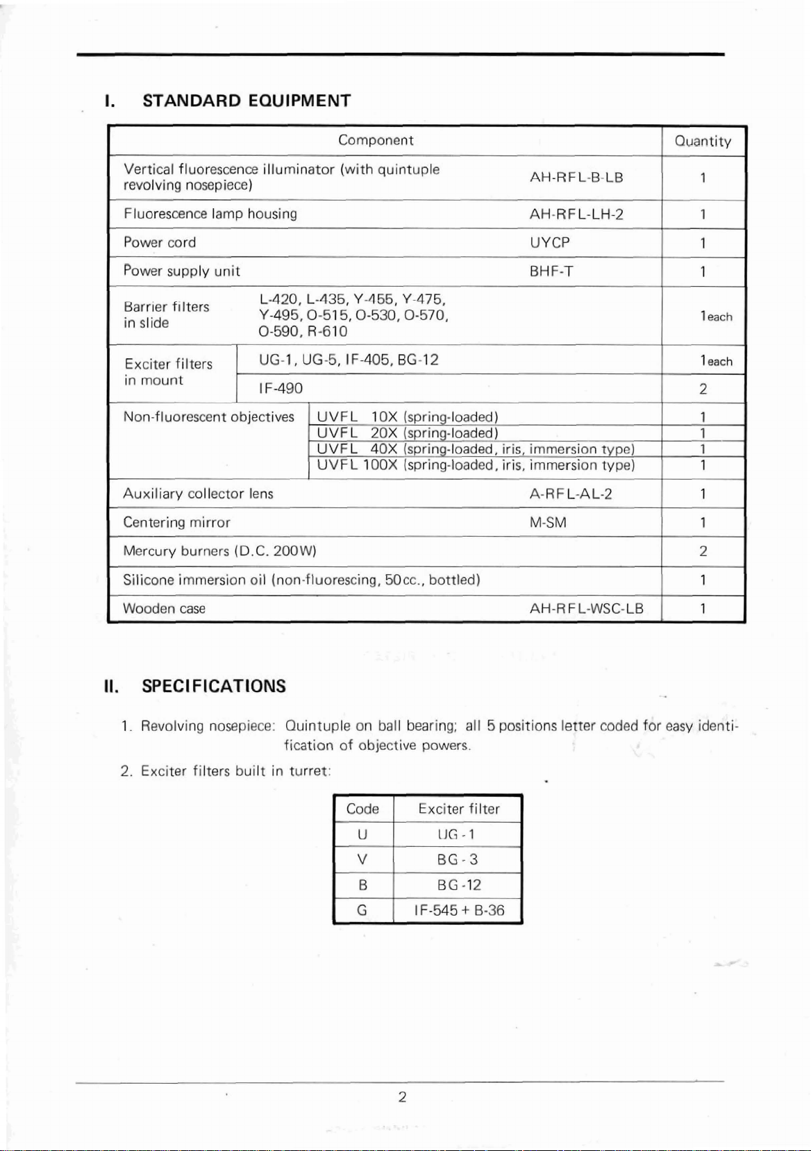
-
I.
STANDARD
EQUIPMENT
Vertical
fluorescence
revolving nosepiece)
Barr~er f ~lters
Non-f
luorescent
objectives
illuminator
(with
quintuple
AH-RFL-&-LB
11.
SPECIFICATIONS
1
.
Revolving
2.
Exciter
nosepiece:
filters
built
Quintuple
fication
in
turret:
on
of
objective
Code
U
V
B
G
ball
bearing;
all 5 positions
powers.
Exciter filter
UG
-
1
BG-3
BG
-12
1
F-545
+
6-36
letter
coded
for
easy
identi-
Page 5
1
)
Dichroic
mirrors:
Mounted
in
slide
and
combined
with
--
built-in
barrier filters.
2)
Magnification
3.
Fluorescent
1)
D.C.
super pressure
mercury
2)
Power
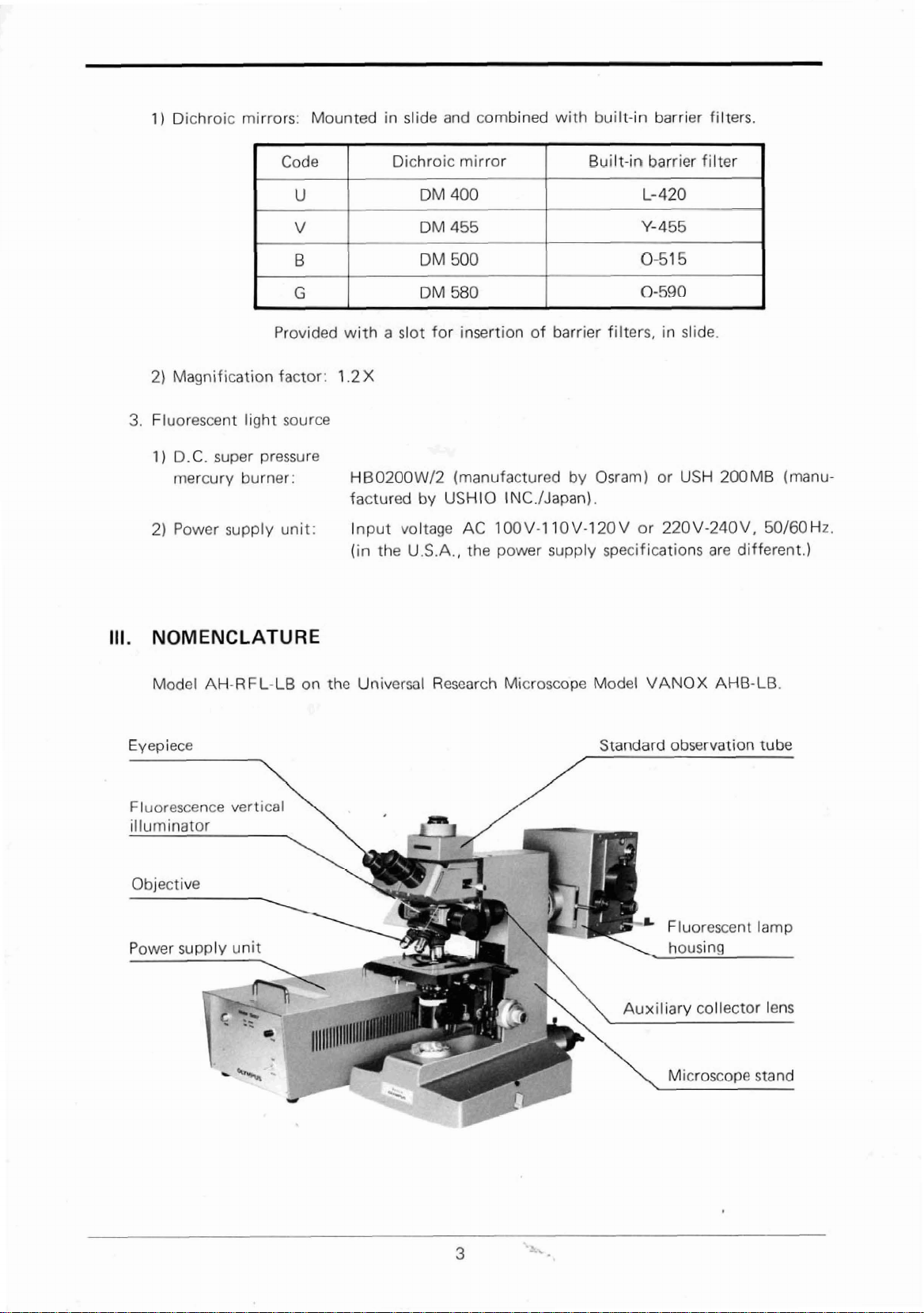
111.
NOMENCLATURE
Model
Eyepiece
supply
AH-RFL-LB
7
Provided
factor:
light
source
burner:
unit:
on
with
a
1.2X
HB0200WJ2
factured
l
nput
(in
the
the
Universal
slot
for
by
voltage
U.S.A.,
Research
insertion
(manufactured
USHlO
AC
the
of
INC./Japan).
100V-3
power
Microscope
barrier
10V-120V
supply specifications
by
Osram)
Model
Standard
filters,
in
slide.
or
USH
or
220V-240V,
VANOX AHB-LB
observation
b
200MB
are
different.)
(manu-
50160
tube
Hz.
Fluorescence
Power
supply unit
vertical
Fluorescent
w
lamp
Page 6

IDENTIFICATION
IV.
A.
Vertical
Fluorescence
AND
Illuminator
FUNCTION
OF
VARIOUS
COMPONENTS
@
Revolving
@
Observation tube clamping
@I
Barrier filter insertion slot:
@
UV
@
Dichroic
@
Field
@
Aperture iris diaphragm ring:
@
Exciter filter turret:
nosepiece:
protective
iris diaphragm ring:
shade:
mirror selector lever: Dichroic
rn
screw:
Provided
tives.
This ilfuminato~ is attached to the circular dovetail
of
the
Place
filter
Make
from fluorescent light.
tion
the dichroic mirror selector lever.
can
Incorporates filters
BG-3
IF-545
tional aperture
with
5
observation tube
the
dust
slide
is
used.
it a rule
of
a
be
selected
(V
+
to
barrrer
mirrors
with this lever.
for violet),
BC-36
(C
(0).
threaded apertures
and
clamped
l@
into this
use
this
shade
Can
fllter
in
mount
combined
UG-1
BG-12
for green violet), with
sfot
to protect your
be
swung
or
with4 built-in barrier filters
(*See
{coded
U
(6
for blue violet) and
to
accept
with
when
out for inser-
when
NOTE
for ultraviolet),
objec-
this
screw.
no
barrier
eyes
operatrng
below.)
an
addi-
@)
Filter mount:
Dust
slide
NOTE:
The
Model
length radiation
long wavelength.
AH-RFL-LB
towards
Accepts
incorporates dichroic mirrors,
the
two
objective
exciter filters
to
illuminate
the
in
mount.
which
reflect short
specimen, while
wave-
passing
Page 7

B.
Fluorescent
Lamp
Hausing
"a
0
7
I
'.
-/
I-.
A'
Ij)
Knurled
a
Shutter
Collector lens
Burner centering
Socket
$I
Reflector centering
Reflector
@I
Connectors:
C.
Power
Supply
iing:
lever:
clamping screw
focusing knob
Attaches
Pull
focusing
knobs
knobs
Accept
Unit
out
knob
the
the
the
lamp
shutter
plugs
housing
lever
of
the
to
the
microscope
to
block
connecting
the
cord.
stand
light.
7:
.
,
Pilot lamp
('2)
Start
8%
Main
5$
Fuse
'3
Connecting
@
Frequency
button
switch
holder
cords
selector
switch
7~
Line
(@
Power
5)
Groundinq
%'
Grounding
Power
voltage
selector
cord connector
terminal
cord
cord
switch
Page 8

D. Auxiliary
F.
Barrier
Collector
Filters
in
Lens
Slide
(10
pcs.)
E.
Exciter
G.
Gntering
Filters
Mirror
in
Mount
(6
pcs.)
Page 9

V.
ASSEMBLY
Prior to
with your fingers.
1.
2.
3.
assembly,
Attach the lamp housing. (Fig.
Place the lamp housing next to the flange of the
opening provided on the microscope limb, with
positioning groove aligned with positioning pin,
and lock by turning the knurled ring clockwise.
Mount: the auxiliary collector lens. (Fig.
Insert the lens into the front of the opening on
the microscope limb.
Attach
1)
2)
3)
the observation tube.
Remove
the
microscope stand, and turn the selector
turret
on
tion
"M.P.".
Check
hand
(levers
Insert
mount
tubs
that
side
pointing upwards).
the
as
remove all dust caps and
the
standard observation
top
of
the microscope stand to posi-
(Fig.
3)
the
two
clamping levers on the right
of
the
dovetail mount are unclamped
tube
dovetail slide into the dovetail
on
the
microscope
far
as
pmibte.
-
1
)
2)
tube
stand and lower the
be
careful not to
-
from
I
1
touch
the optical elements
I-.,
Fig.
1
Fig.
2
-<
-
.
-.
4)
Firmly lock the
lever.
4.
Attaeh
1
2)
5.
Mount objectives and eyepieces.
the
)
Clamp the
edge
@
Clamp
tion tube in
revolving
the
vertical fluorescence
of
nosepiece.
tube
UV
protective
the vertical illuminator. (Fig.
vertical
illuminator to
the
same manner as the standard
with
shade
the
upper clamping
illuminator.
@
to the upper
the
4)
observa-
Fig.
Fig.
3
4
Page 10

6.
Install the mercury burner.
Wipe the surface of the mercury burner clean with an alcohol%ther mixture, benzine, etc,
Use great
and when installing,
1)
Loosen the
in
Fig.
care
to make sure that no dirt, fingerprints, etc., are left on the bulb surface,
be
carefull not to touch the bulb portion.
socbt
5.
At this time, pay attention to the following:
clamping screw
0,
and lift up the socket
as
shown by the arrow
VI.
OPERATION
A.
Ignition of
(1) Be sure to
(2)
Note that the connecting cord prevents socket removal
2)
Remove
3)
Insert the lower electrode (marked with
with clamping nut
mounting terminal, and lock with clamping nut
burner envelope
the
use
a
DC
type mercury burner (HB0200W/2 or USH200MB).
the
retainer of the socket terminals, used for transportation.
0,
then insert the upper electrode into the slot of the upper
@
90'
away from the optical axis. (Fig.
Burner
unless
"+")
into the bottom terminal and tighten
@.
Be sure to turn the pearl on the
it
is
6)
Fig.
6
unplugged.
1)
Ascertain that the line voltage selector switch on the power supply unit is set to conform
with the local mains voltage. (This switch can
set to the following voltages: 100V-110V-120V or 220V-240V.)
2)
Ascertain that the freqnency selector switch on the power supply unit is set to conform
with the focal mains frequency (60Hz or 60Hz). If ypu find the switch is not correctly
positioned, unscrew the transparent cover and set the switch correctly.
3)
Check complete electric connection.
4)
Turneon the main switch of the power supply unit.
light.
5)
Press the start button, and the burner will ignite.
*
If
the line voltage is lower than
6)
Do not switch
*
Repeated on-off switching considerably shortens the burner life. After the burner is
switched
off,
off
the burner within
do
not re-ignite for 3 minutes or more in order
10%
of the rated voltage,
15
8
be
turned with a screwdriver, and can be
At
the
same
the
minutes after ignition.
time,
the pilot lamp will
arc will sometimes flicker.
to
give
it
time to cool.
-
Page 11

Disconnect the power cord from
the power
B.
Burner Centration
After the arc has stabilized (2-4min.). center the burner as follows:
1) Rotate the exciter filter turret until the turret
click stops at the
2)
Open the shutter by pushing the shutter knob
all the
3)
Rotate the knurled rings
iris
iris
4)
swing' the
5)
Slide the dichroic mirror selector lever to the
"6"
6)
Insert the barrier filter 0-570 into the slot
supply
way.
diaphragm) and
diaphragm) to the
-
position.
unit.
"G"
position.
"f"
"Br"
@
MAX.
UV
protective shade to the left.
the
AC
@
(for the field
(for the aperture
position. (Fig.
*
\
outlet, and remove the fuse holder from
1
I
7)
of
the vertical illuminator.
Fig.
7
7) Place the burner centering mirror on the stage, and focus
8)
Pull out the light path selector lever built-in the observation tube
(yellow-green line).
9)
Remove the
As
tube.
of brightness) at the back of the objective.
NOTE:
If
reflected
manipulating the reflector centering knobs, because the reflected image moves
you
a) Bring the real image into focus with the collector lens focusing knob.
b)
c)
d)
e) Superimpose the real and reflected images.
*
cap
from
the photo eyepiece attachment hole on top of
you look through the opening, you can
the burner
operate the reflector centering knobs, while the real image does not.
Bring the real image to position
knobs.
Bring the real
by means of the reflector centering knobs. (Fig.
Equalize the sizes of the reflected and real
knobs.
As
a
is
out of center, four spots of brightness
images.
rule, this procedure
The reflected image can
and
reflected images into symmertrical positions with each other
is
required only after burner replacement.
see
be
(Fig.
8b) by means
the arc images of the burner (spots
identified from the real image,
8c)
images
on
it
with the
up
can
be
of
with the reflector focusing
10X
objective.
to the
CV
position
the
obsemtion
seen
as
the
real
the burner centering
and
by
as
w
Reflscted
image
(b)
Fig.
8
Page 12

C.
FEuoresoence
1
)
Bring the area
mitted
manual
2)
Switch
Microscopy
of
the specimen to
light,
emitted
for
the
Universal Research
off
the transmitted light
from
exciter filter and dichroic mirror for
be
observed
the halogen
Microscope
socrrm,
your
into
the field of
or
tungsten filament
Model
and
select
the
specimen.
view,
and
focus
bulb.
(See
the instruction
VANOX-AHB-LB.
most suitable combination
with trans-
of
NOTE:
3)
4)
*
5)
Additional exciter filters in mount
used
as
desired. For details read
Stop
down
the field iris diaphragm
Stop down the aperture
Use
non-fluorescing
1OOX
After
gauze
(immersion
use,
moistened with xylene (no alcohol
carefully wipe
silicone
type)
Never leave immersion liquid
the
seriously impair
6)
The objectives
performance
UVFL40X
vided with iris diaphragms. It
to
increase contrast
7)
The
objective
spherically
glass.
For use
correct
of
the correction collar,
and
UVFC40X
for a thinner or thicker cover glass,
while looking through the
be
seen in
best
definition.
and
iris
diaphragm
immersion
objectives.
off
the
on
the
of
{immersion
is
recommended
barrier fitters in
E.
"Use of Filters".
("Fa')
until it is within the field
("A")
to ensure proper contrast.
oil
for
UVFL4OX
immersion liquid deposited on
or
ether should
lens
the
objective.
type)
surfaces
and
after
UVFL
to
stop
slide,
both provided,
of
(immersion type)
the
be
used,)
use
as
remnants of
lOOX
down
(immersion
the iris diaphragm slightly
image definition.
(dry) is provided with a correction collar which
as
well
as
a
0.1
set
it
at
microscope
and
0.17rnm
focusing
and
then
turn it in either direction
on
the specimen unti
view.
lens
the
type)
7mm
t
the
can
and
UVFL
surfaces
liquid will
are
can
be
set to
thick cover
image
be
with
pro-
can
8)
D.
Burner
1
2)
3)
When
fluorescence
it
is
good practice
to
turn
off
useful life
the mercury burner, since repeated on-off switching considerably shortens the
of
Replacement
)
The
average
be
kept
longer
It
is recommended to
at
the
end
of
Do
not
touch
the
main switch
observation
to
cut off
the
the burner.
life
of
burner
than
-2
hours.
keep
is
about
a
its life expectancy.
the burner
is
off,
for
and disconnect the lower connecting
is
to
beam
record
about
be
interrupted briefly
of
light
by
means
400
hours, provided
of
the
operating time of
10
minutes after switching
of
that
(for
the
each
cord
about
30
minutes or less),
opaque
shutter rather than
lighting duration should
each
off.
from
burner,
Then,
and
ascertain
the
lamp housing.
replace
it
that
Page 13

E.
Use
of
Filters
Excitation
method
Ultraviolet
Violet
Blue
Green
Excitation methods
1)
Ultraviolets:
Exciter filter
and
applications
Exciter filter
turret
(UG-1)
U
V
{BG-3)
B
(BG-12)
None
G
(
I
F-545
BG-36)
Spectral
band
Wide
Narrow
Wide
Narrow
Wide
Narrow
Narrow
The line spectrum at bright lines 334nm and 365nm.
Fluorescence antibody method
Congo red test
+
(F
ITC)
Exciter filter
in mount
None
UG-1
UG-5
I F-405
BG-12
I
F-490
---
None
(2
pcs.)
Dichroic mirror
selector knob
U
(DM
400
+
L-420)
V
(DM
455
+
Y-455)
B
(DM
500
+
0-51
5)
G
(DM 580
0-590)
+
Barrier filter
in mount
L-420 and
UP
Y-475
and
UP
0-530
and
UP
R-610
2)
Violet: The line spectrum at bright lines 405nm and 435nm.
Catecholamine
3)
Blue:
Fluorescence antibody method
Acridine yellow and acridine orange
Auramine
Tetracycline
4)
Green: The line spectrum
Fluorescence antibody (TRITC)
Feulgen
Rhodamine
The line spectrum at bright lines 405nm
trum at 490nm.
B
(FITC)
at
bright line 546nm.
and
435nm,
and continuous spec-
Fuchsin
Page 14

VII. OPTICAL DATA
Magnif ieation
'OX
20X
*40X
UVFL
(immersion
40X
type)
1 OOX
(immersion
type)
Focal length (mm)
Total magnif.
N
K5X
(Field
21
No.
WHK'OX
(20)
WHK1
5X
(14)
*
The resolving power
**
Optionally available.
Focal depth
.
Field
Total magnif.
Focal depth
Field of
Total magnif.
Focal depth
Field
of
of
view
view
view
0.4
1.16
15.84
0.84
50X
(w)
(mm)
(MI
(mm)
(p)
(mm)
is
28.83
2.1
lWX
15.7
2.0
150X
11.33
1.4
obtained with fully opened aperture diaphragm.
0.65
1.03
8.1 1
0.52
lOOX
9-05
1.05
2WX
5.02
.O
1
300X
3.67
0.7
0.85
0.25
4.59
0.395
Collection
collar
200X
3.66
0.53
4WX
2.1 2
0.5
600X
1.60
0.35
lris diaphragm
200X
4WX
600X
1
.30
0.1
4.56
0.26
2.28
0.53
1.25
0.5
0.92
0.35
1.30
1
0.14
1.91
0.26
lris diaphragm
500X
1.05
0.21
1,OOOX
0.65
0.2
1,500X
0.51
0.14
L
Technical terms:
Working distance:
(W.
D)
Numerical aperture:
A.)
(N.
Resolving power:
Focal depth:
Field number:
Field
of
view diameter: The actual size of the field of view in mm
The distance from cover glass to the closest point
of
tive when focused on the specirnan.
N.
A.
The
represents a performance number which
pared to the relative aperture (f-number)
N.
A.
values can
be
used for directly comparing the resolutions of
all types of objectives. The larger the N.
of
a camera lens. The
A.,
the higher the resolv-
can
ing power.
The
ability of a lens to register small details. The resolving power
of a lens
The distance between the upper and lower limits of
the image formed by an optical system.
aperture iris diaphragm, the focal
the
A
number that represents the diameter
field diaphragm that
is
measured
N.
A.
of an objective, the shallower
by
is
formed
its
ability to separate two points.
sharpness
As
you stop down the
depth
becomes
the
in
by
the lens in front of
larger, The larger
focal depth.
mm of the image of the
it.
on
the object surface.
the
objec-
be com-
in
Page 15

VIII.
SPECTRAL
1.
Barrier filters
2.
Ultraviolet exciter filters
CHARACTERISTICS
in
slide
m
OF
FILTERS
If
400
Ill
I"'"'
IJ
III
WO
700
War.len#ll~
am
181)
3.
Violet exciter filters
4.
Blue
exciter
5.
Green exciter
filters
filters
Page 16

*
+--&q
.
-
"
i
OLYMPUS
7
P
v;
i
h
*
I.
.
-1.
'
r
OPTIC
,
CO.,
-7
C-
LTC).
1
12-2,
WISHISHINIUKU I -CHOME,
SHINJUKU-KU
TOKYO,
JAPAN.
 Loading...