

Page 1

INSTRUCTIONS FOR USE
PERISTALTIC PUMP UNIT
AFU-100
REF: WB950167 (100…240 V~)
WB135745-W10
Page 2

Page 3

Olympus AFU-100 EN Instructions for Use
Contents
1 Important information
1.1 Intended use
1.2 Instructions for use
1.3 User qualification
1.4 Peristaltic pump unit compatibility
1.5 Repair and modification
1.6 Signal words
1.7 Danger, warnings and cautions
2 General description
3 Inspection prior to use
4 Symbols, definitions and functions
4.1 Symbols and descriptions
4.1.1 Front panel
4.1.2 Rear panel
4.1.3 Packaging
4.1.4 Pump tube
4.2 Front panel
4.2.1 Buttons / Switches
4.2.2 Indicators
4.2.3 Displays
4.3 Rear panel
5 Accessories
5.1 Footswitch
5.2 Pump tube
6 Installation and commissioning
6.1 Installation of equipment
6.2 Connection / disconnection of pump head
6.3 Connection to an AC mains power supply
6.4 Equipotential bonding
6.5 Connection of footswitch
6.6 Connection to an electrosurgical unit
WB135745-W10
3
Page 4

Instructions for Use EN Olympus AFU-100
7 Operation
7.1 Power supply
7.2 Acoustic signals and tone volume adjustments
7.3 Pump tube insertion and connection
7.4 Flow selection
7.5 Store and recall flow levels
7.6 Activation / deactivation of the flow
7.7 Procedure after use
8 Cleaning, storage and disposal
8.1 Cleaning
8.2 Storage
8.3 Disposal of the unit
9 Troubleshooting
9.1 Error codes and measures
9.2 Periodic safety checks
9.3 Returning the peristaltic pump unit for repair
10 System chart
11 Specifications
11.1 Pump tube characteristics
11.2 Technical data
12 Electromagnetic compatibility (EMC)
12.1 Guidance and manufacturer’s declaration – electromagnetic emissions
12.2 Guidance and manufacturer’s declaration – electromagnetic immunity
12.3 Recommended separation distances between portable and mobile high
frequency communication equipment and the peristaltic pump unit
4
WB135745-W10
Page 5

Olympus AFU-100 EN Instructions for Use
1 Important information
1.1 Intended use
The AFU-100 is a peristaltic pump unit intended for irrigation of instruments or irrigation
/ flushing / cleansing of tissue surfaces and wounds supporting endoscopic diagnosis or
therapy.
Contraindications:
The peristaltic pump unit must not be applied for intravenous fluid administration.
1.2 Instructions for use
These instructions for use contain essential information on using this peristaltic pump
unit safely and effectively. Before use, thoroughly review these instructions for use and
the instructions for use of all equipment which will be used during the procedure. Use
the equipment as instructed. Keep this and all related instructions for use in a safe,
accessible location. If you have any questions or comments about any information in
these instructions for use, please contact Olympus or your distributor.
1.3 User qualification
The user must be a physician or medical personnel under supervision of a physician
and must have received appropriate training in using this peristaltic pump unit. These
instructions for use, therefore, do not explain or discuss medical procedures.
In addition, the user must undergo an instruction / training for the use of this unit. The
instruction / training will be provided by authorised representatives of Olympus or your
distributor during installation and commissioning.
Federal Law of the USA restricts this device to use by, or on the order of, a
physician.
1.4 Peristaltic pump unit compatibility
Refer to chapter 10 (System chart) to confirm that this peristaltic pump unit is
compatible with the ancillary equipment being used. Using incompatible equipment can
result in patient injury and / or equipment damage.
1.5 Repair and modification
This peristaltic pump unit does not contain any user-serviceable parts. Do not
disassemble, modify, or attempt to repair it; patient or user injury and / or equipment
damage may result. Repairs must only be carried out by Olympus or a firm authorised
by Olympus. Some problems that appear to be malfunctions may be corrected by
referring to chapter 9 (Troubleshooting). If the problem cannot be resolved using the
information in chapter 9, contact Olympus or your distributor.
WB135745-W10
5
Page 6

Instructions for Use EN Olympus AFU-100
1.6 Signal words
The following signal words are used throughout these instructions for use:
DANGER
d
WARNING
CAUTION
Indicates an imminently hazardous situation which, if not avoided, will
result in death or serious injury.
Indicates a potentially hazardous situation which, if not avoided, could
result in death or serious injury.
Indicates a potentially hazardous situation which, if not avoided, may
result in minor or moderate injury. It may also be used to alert against
unsafe practices or potential equipment damage.
NOTE
Indicates additional helpful information.
1.7 Danger, warnings and cautions
Follow the dangers, warnings and cautions given below when handling this peristaltic
pump unit. This information is to be supplemented by the dangers, warnings and
cautions given in each chapter.
User-related error prevention
WARNING Improper use
The safety and effectiveness of medical procedures depends not only on the design of
the equipment used, but also to a major extent on factors which are under the control of
the user. It is therefore extremely important to read, understand and follow the
instructions supplied with the peristaltic pump unit and the accessories in order to
ensure safety and effectiveness.
Always use the peristaltic pump unit as outlined in these instructions for use. Improper
use will not only impede functions and prevent optimum performance, but may cause
equipment damage and / or complications. Before each use, always inspect the
equipment as outlined in these instructions for use.
6
WB135745-W10
Page 7

Olympus AFU-100 EN Instructions for Use
with e
Environmental conditions
CAUTION Interference of the unit with other equipment
Be sure that this peristaltic pump unit is not used adjacent to or stacked with other
equipment (other than the components of this peristaltic pump unit or system) to avoid
electromagnetic interference.
Before use, thoroughly confirm the compatibility of all equipment.
To ensure electrical safety, the peristaltic pump unit should not be used in conjunction
quipment whose safety in combined use is not guaranteed.
The peristaltic pump unit complies with the electromagnetic compatibility (EMC)
standard. Nevertheless, when the peristaltic pump unit is active it may disturb
neighboring electronic equipment. Follow the instructions in chapter 12 (Electromagnetic
compatibility) regarding electromagnetic ambient conditions.
Do not use the peristaltic pump unit in a location exposed to strong electromagnetic
radiation (microwave or short-wave medical treatment equipment, Magnetic Resonance
Imaging, radio or mobile phone equipment). Peristaltic pump unit malfunction can occur.
CAUTION Unsuitable temperature and humidity
The peristaltic pump unit should only be used under the conditions as described in
chapter 11.2 (Technical data). Use under other conditions may impede normal
performance and / or result in equipment damage.
Accessories
WARNING Mechanical stress
Do not apply excessive bending, straining, or squeezing force to any cords or tubes. It
may cause malfunction.
CAUTION Non-compatible accessories and accessory damage
The peristaltic pump unit may only be used with compatible accessories.
Before use, the peristaltic pump unit and accessories must be examined for damage. All
communication cables and its plugs must be free of scratches and cracks. Cables and
accessories with damaged insulation or connections must not be used.
Electric shock
WARNING Grounding failure
To prevent the risk of electric shock, the housing of the peristaltic pump unit must be
grounded. Always connect the power cord plug to a properly grounded wall outlet. Do
not use a 3-pin / 2-pin adapter, as it can impair safe operation of the unit.
WARNING User shock
To prevent user shock, malfunction and damage of the peristaltic pump unit, keep
liquids away from all electrical equipment. If liquid gets on or into the peristaltic pump
unit, terminate operation immediately and contact Olympus or your distributor.
CAUTION Injury during servicing
When the housing is opened, there is a danger of electric shock. The unit must only be
serviced by authorised technicians.
WB135745-W10
7
Page 8

Instructions for Use EN Olympus AFU-100
Fire / Explosion
DANGER Explosion
This peristaltic pump unit is not explosion-proof. Do not use the unit within an explosion
zone.
WARNING Risk of fire
Disconnect the power plug before changing the fuses! Replace fuses as marked. The
fuses must only be replaced by authorised technicians.
WARNING Ignitable cleaning- and disinfection agents
Flammable agents used for cleaning and disinfection must be allowed to evaporate
before the peristaltic pump unit is used.
Non-flammable agents should be used for cleaning and disinfection wherever possible.
Procedural hazards and complications
DANGER Procedural hazards and complications
The safety of medical procedures will be greatly enhanced by a thorough knowledge of
the medical literature on the subject. Study of specific information on the hazards and
complications of the procedure in question is especially recommended.
WARNING Flow performance
If the peristaltic pump unit fails and the flow is stopped during treatment, it may be
impossible to finish the treatment.
Should any abnormal flow be suspected during operation, immediately terminate the
use of the peristaltic pump unit. If deactivation is not possible, switch off the peristaltic
pump unit. Otherwise, malfunction of the equipment may cause an unintended increase
in the flow.
CAUTION Unit defect
In the event of a defect or malfunction in the unit, an undesirably high flow output may
occur.
8
WB135745-W10
Page 9
Olympus AFU-100 EN Instructions for Use
2 General description
The AFU-100 peristaltic pump unit is a roller pump. The rollers of the pump rotors
squeeze the inserted pump tube so that the liquid in the pump tube is transported. This
enables liquid media to be transported without coming into contact with the peristaltic
pump unit. Sterile liquids (e.g. isotonic saline solution) thus remain sterile, provided that
a sterile tube set is used.
The maximum flow rate is 270 ml and 600 ml per minute with two different tube sets
(see chapter 11.1, Pump tube characteristics) offered as single use items. In addition,
three memory buttons provide fast access to preset flow levels. The peristaltic pump
unit can be connected to an electrosurgical unit by an interface, allowing operation of
the peristaltic pump unit by a special button on the electrosurgical unit’s footswitch.
The pump rotor is equipped with a protective cover, which automatically stops the
rollers from rotating if it is opened while the peristaltic pump unit is activated, and thus
prevents possible injuries.
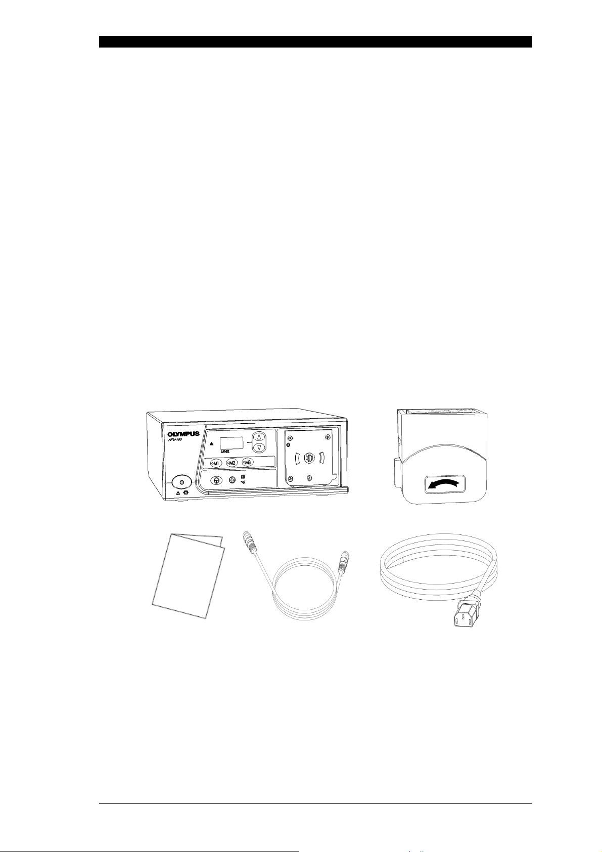
3 Inspection prior to use
Verify that all items shown below are contained in the package. Inspect each item for
damage. If the peristaltic pump unit is damaged, a component is missing or you have
any questions, do not use the peristaltic pump unit. Contact Olympus or your distributor
immediately.
Peristaltic pump unit
Instructions for use
Communication cable
Pump head
Power cord
The following items are optional and may be purchased separately from Olympus or
your distributor:
• Footswitch
• Pump tube
WB135745-W10
9
Page 10
Instructions for Use EN Olympus AFU-100
M2
4 Symbols, definitions and functions
4.1 Symbols and descriptions
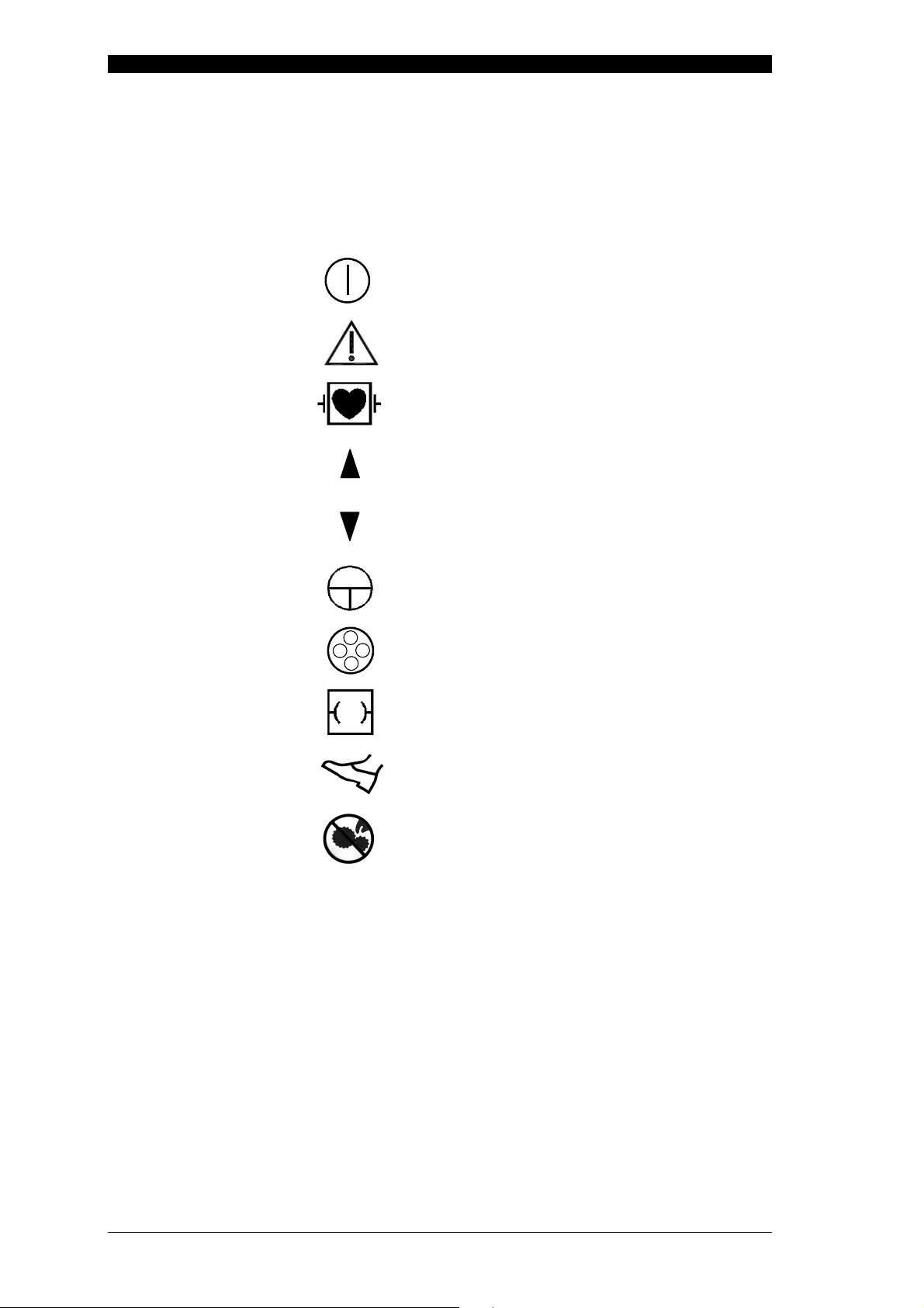
4.1.1 Front panel
Power on / off
Caution
Defibrillation proof type CF applied part
(cardiac application)
Up (increase flow level)
Down (decrease flow level)
Flow on / off
Flow activation
Communication assignment with an
electrosurgical unit
Communication assignment with footswitch
Do not allow fingers to contact moving parts
Memory 1
Memory 2
Memory 3
10
WB135745-W10
Page 11
Olympus AFU-100 EN Instructions for Use
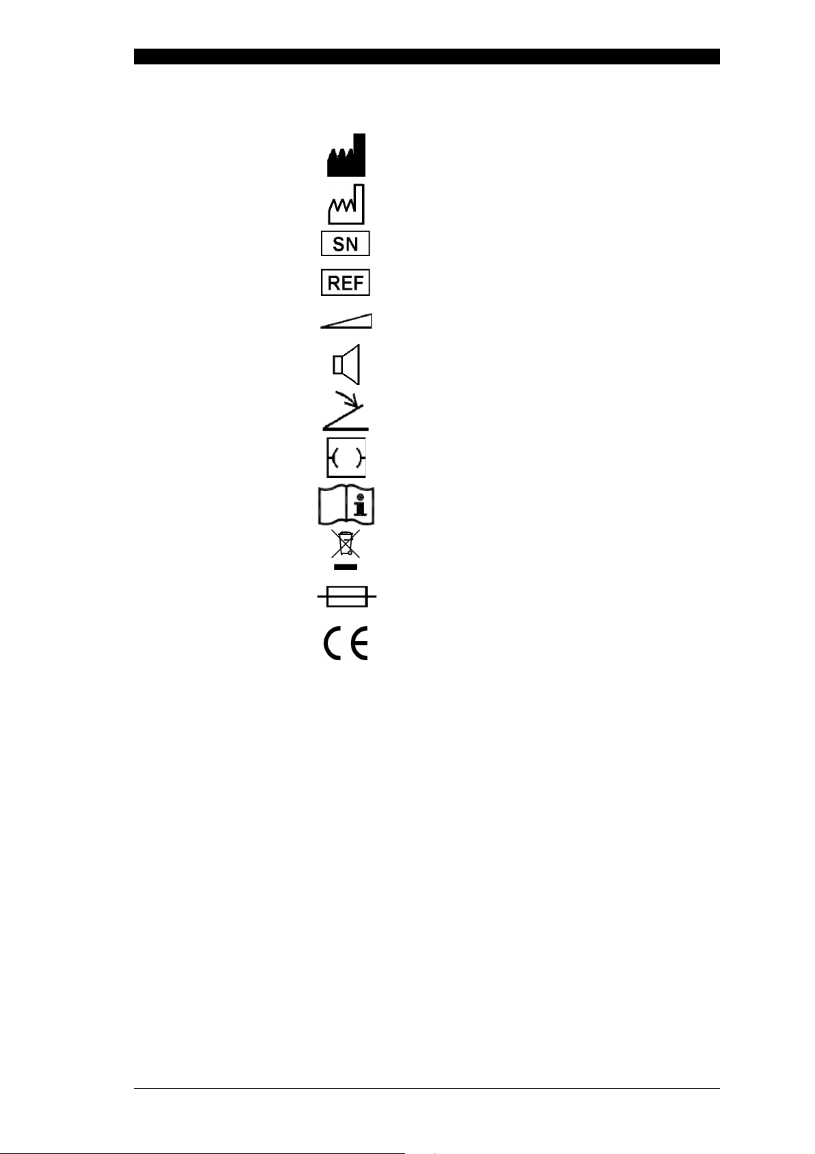
4.1.2 Rear panel
Manufacturer
Date of manufacture
Serial number
Reference number
Indication of the direction of higher volume
Loudspeaker
Footswitch connection
Interface for electrosurgical unit connection
Operating instructions
Waste electrical and electronic equipment
Fuse
Product carries the CE mark
WB135745-W10
11
Page 12

Instructions for Use EN Olympus AFU-100
4.1.3 Packaging
Keep away from rain
Fragile; handle with care
4.1.4 Pump tube
This way up
Temperature limit during transport and
storage
Stacking limit by number (including lowest
box)
Atmospheric pressure limitation during
transport and storage
Relative humidity limitation during transport
and storage
Quantity
Disposable article – Do not reuse
Do not resterilise
Sterilised with gamma radiation
Relative humidity limitation for storage (during
transport)
Temperature limit for storage (during
transport)
12
WB135745-W10
Page 13

Olympus AFU-100 EN Instructions for Use
Memory 3 button (3)
Memory 1 button (1)
Flow activation
/
deactivation
4.2 Front panel
Level display (14)
Error indicator (7)
Power switch (0)
Up / down button (5 / 6)
Memory 1 indicator (8)
button (4)
Memory 2 indicator (9)
Flow activation indicators (11)
Memory 2 button (2)
Memory 3 indicator (10)
Electrosurgical unit assignment indicator (12)
Footswitch assignment indicator (13)
WB135745-W10
13
Page 14

Instructions for Use EN Olympus AFU-100
4.2.1 Buttons / Switches
0 Power switch
This switch turns on and off the peristaltic pump unit.
1 / 2 / 3 Memory 1 / 2 / 3 button
The memory buttons are used to store and recall previously stored flow
levels. The level display (14) shows the selected flow level.
4 Flow activation / deactivation button
This button is used to activate / deactivate the peristaltic pump unit with the
selected flow level as shown in the level display (14).
5 / 6 Up / down button
These buttons increase / decrease the value displayed at the level display
(14).
4.2.2 Indicators
7 Error indicator
This indicator illuminates red if any error occurs.
8 / 9 / 10 Memory 1 / 2 / 3 indicator
11 Flow activation indicators
12 Electrosurgical unit assignment indicator
13 Footswitch assignment indicator
4.2.3 Displays
14
The corresponding indicator signals if one of the memory buttons (1 / 2 / 3)
is pressed.
These indicators signal the activation of the peristaltic pump unit with the
selected flow level as shown in the level display (14).
This indicator signals the communication assignment with an electrosurgical
unit.
This indicator signals the communication assignment with the peristaltic
pump unit footswitch.
Level display
This display shows the currently selected flow level.
3 … 100
E##
Flow level
Error notice and related error number (##)
14
WB135745-W10
Page 15

Olympus AFU-100 EN Instructions for Use
Footswitch connector (15)
Equipotential bonding connector (17)
Volume control (20)
4.3 Rear panel
Type plate (19)
Communication port electrosurgical unit (16)
Mains connector with integrated fuses (18)
15 Footswitch connector
This terminal connects the footswitch with the peristaltic pump unit, so that
the flow can be activated / deactivated by the footswitch pedal (21).
16 Communication port for electrosurgical unit
This terminal is used for the communication between the peristaltic pump unit
and an electrosurgical unit.
17 Equipotential bonding connector
This terminal is used for potential equalization.
18 Mains connector with integrated fuses
This terminal serves as a connection to the mains power supply.
19 Type plate
The type plate contains specific information about the peristaltic pump unit
regarding type of device, reference number (REF), line voltage range, power
consumption, serial number and the registered office of the manufacturer.
WB135745-W10
20 Volume control
This knob is used for adjusting the volume.
15
Page 16

Instructions for Use EN Olympus AFU-100
footswitch
.
5 Accessories
5.1 Footswitch
Footswitch pedal (21)
21 Footswitch pedal
This pedal is used to activate / deactivate the selected flow level.
22 Footswitch plug
Connects the footswitch with the peristaltic pump unit on the rear panel.
NOTE
5.2 Pump tube
The achievable flow rate depends on the diameter of the inserted pump tube, the used
instrument (including its accessories) and the setting of the flow level (see chapter 11.1,
Pump tube characteristics, chapter 7.3, Pump tube insertion and connection and
chapter 7.4, Flow selection).
Footswitch plug (22)
The footswitch is an optional accessory. The selected flow level can
also be activated / deactivated with the flow activation / deactivation
button (4) as well as with a special button on the electrosurgical unit’s
6 Installation and commissioning
The unit must be properly installed and commissioned by Olympus or your distributor or
by a person or firm commissioned and authorised by the manufacturer.
Prepare the peristaltic pump unit and other equipment to be used with this peristaltic
pump unit before each use. Refer to the instructions for use of the equipment, and
install and connect all equipment as described on the following pages.
16
WB135745-W10
Page 17

Olympus AFU-100 EN Instructions for Use
Locking lever
6.1 Installation of equipment
CAUTION
If the peristaltic pump unit is placed on a cart, the cart must be of
Never place the peristaltic pump unit on its side or upside down.
If the peristaltic pump unit is lifted up, do not hold the unit at the fuse
NOTE
Install the unit on a stable, level surface. Otherwise, the unit could fall,
causing equipment damage and / or injury to the user or patient.
adequate strength and size to hold the unit securely.
Otherwise, the peristaltic pump unit may not work correctly.
holder at the rear panel to prevent damage of the unit.
Place the instructions for use near the peristaltic pump unit or in another
easily accessible place.
Before using an optional item, thoroughly review and understand the
instructions for use provided with that item and check the compatibility
with the peristaltic pump unit.
Specifications, design and accessories are subject to change without
any notice or any obligation of the manufacturer.
6.2 Connection / disconnection of pump head
Connection of pump head
1) Engage the pump head drive slot with the end of the pump drive shaft
(approximately 45° position, see fig. 6.1). Continue to align the pump head until the
bayonet engages with the mounting plate. Ensure that the arrow on the front of the
pump head is pointing to the left side.
2) Turn the pump head clockwise until it locks into an upright and secure position.
Disconnection of pump head
1) Push the locking lever (see fig. 6.1) back and turn the pump head counterclockwise
until it is free from the mounting plate.
2) Remove the pump head.
Fig. 6.1: Connection / disconnection of pump head
WB135745-W10
17
Page 18

Instructions for Use EN Olympus AFU-100
6.3 Connection to an AC mains power supply
1) Confirm that the power of the peristaltic pump unit is off.
2) Connect the power cord to the mains connector (18) of the peristaltic pump unit
(see fig. 6.2).
3) Connect the power plug of the power cord directly to a grounded wall outlet which
meets the power requirements indicated on the electrical rating plate on the rear
panel of the peristaltic pump unit.
Fig. 6.2: Connection of the power cord
DANGER
CAUTION
Connect the power plug of the power cord directly to a grounded wall
outlet or to a multiple power socket outlet equiped with an insulating
transformer of protection class I, conforming to IEC 60601-1. The
multiple power socket outlet shall conform with the requirements of the
IEC 60601-1-1 standard. In this case, observe the maximum permitted
current or power loading of the multiple power socket outlet and the
insulating transformer.
Always use the power cord provided with the peristaltic pump unit or a
cable of similar quality (see chapter 11.2, Technical data). Never
attempt to modify the power cord.
Firmly plug in the power cord so it will not accidentally be dislodged
during the operation.
If the same circuit breaker is used to supply power to other electrical
equipment, carefully consider the power requirements of the additional
equipment and use circuit breakers that have ample capacity.
Otherwise, the peristaltic pump unit does not work correctly.
Portable multiple power socket outlets must not be placed on the floor.
Do not use an additional extension cable or other multiple power socket
outlets that are not expressly approved by the manufacturer for joint
use.
18
WB135745-W10
Page 19

Olympus AFU-100 EN Instructions for Use
NOTE
6.4 Equipotential bonding
To increase electrical safety, the unit can be connected to the equipotential bonding
system of the treatment room. All equipment housings that come into contact with the
patient are electrically connected in order to prevent low-frequency electrical currents
from endangering the patient in the event of a defect in the conventional protective
conductor system.
Before connecting to the power supply, check that the supply voltage
agrees with the electrical data on the type plate of the peristaltic pump
unit.
If the voltage of the facility is different from the voltage indicated on the
type plate of the peristaltic pump unit, contact Olympus or your
distributor.
6.5 Connection of footswitch
Before connecting, confirm that the footswitch plug (22) is free of scratches and cracks
and that the footswitch pedal (21) is not damaged. Align the footswitch plug (22) so that
the keying is facing down. Insert the footswitch plug (22) into the footswitch connector
(15) of the peristaltic pump unit on the rear panel and rotate the fastener ring fully
clockwise to tighten it (see fig. 6.3).
Fig. 6.3: Connection of the footswitch
CAUTION
Do not connect products other than the footswitch for this peristaltic
WB135745-W10
Fastener ring
The footswitch plug is not waterproof, and liquid such as water must not
19
get into the plug.
pump unit to the footswitch connector (15). Otherwise, the footswitch
might not function and may cause patient injury and / or damage of the
equipment.
Page 20

Instructions for Use EN Olympus AFU-100
NOTE
If the peristaltic pump unit is connected via the communication cable
with an electrosurgical unit and communication is established, the
footswitch of the peristaltic pump unit cannot be used. In this case, the
peristaltic pump unit will be controlled by the electrosurgical unit’s
footswitch.
6.6 Connection to an electrosurgical unit
The peristaltic pump unit together with an electrosurgical unit can build a system as
shown in fig. 6.4. If the communication to an electrosurgical unit is established and both
units are switched on, a special button on the electrosurgical unit’s footswitch activates
the pump flow.
Align the plugs of the communication cable that the keying is facing down and insert the
plugs into the communication ports of the electrosurgical unit and the peristaltic pump
unit and rotate the fastener rings fully clockwise to tighten it (see fig. 6.4).
Fig. 6.4: Connection of an electrosurgical unit (e.g. ESG-100) and the peristaltic pump
unit
NOTE
It is recommended to position the electrosurgical unit on top of the
peristaltic pump unit to avoid spilling of liquids over the electrosurgical
unit.
7 Operation
Prepare this peristaltic pump unit and other equipment to be used with this unit for the
particular operation. Refer to the respective instructions for use for each item. Confirm
that the connections of the power cord, footswitch, pump tube and instruments are
secure and correct.
20
WB135745-W10
Page 21

Olympus AFU-100 EN Instructions for Use
WARNING
Before each use, inspect this unit as instructed below. Inspect other
equipment to be used with this unit as instructed in their respective
instructions for use. Should the slightest irregularity be suspected, do
not use the peristaltic pump unit and refer to chapter 9
(Troubleshooting). If the irregularity is still suspected after consulting
chapter 9, contact Olympus or your distributor. Damage or irregularity
may compromise patient or user safety and may result in more severe
equipment damage.
7.1 Power supply
Switch on the peristaltic pump unit with the power switch (0). The unit executes a self
test. All indicators of the unit illuminate sequentially during the self test and the three
numbers of the level display (14) count from 0 to 9. At the end of the self test, all
indicators of the unit illuminate simultaneously and an alarm tone can be heard. The unit
is prepared for use and recalls the last flow level used.
By using the peristaltic pump unit for the first time there will be a default setting of the
flow level and the memory buttons (1 / 2 / 3).
By switching on the peristaltic pump unit after one or more procedures have been
done, the last used flow level is presented at the level display (14). Before starting the
procedure, confirm the correctness of the settings.
CAUTION
NOTE
The self test cannot be interrupted before it is finished.
If the peristaltic pump unit fails to start up (no indicators illuminates and
the level display (14) is off), confirm that the power cord is connected
securely to a grounded wall outlet and the mains connector (18) on the
peristaltic pump unit and confirm that the grounded wall outlet is
powered. If it still fails to start up, remove the power cord from the
grounded wall outlet and contact Olympus or your distributor.
Equipment damage or malfunction may have occurred and fire or
electric shock can result.
To enable the immediate continuation of the procedure in case of a
power failure (less than 15 seconds) or unintended switching off and on
(within 15 seconds), no self test will be performed. The peristaltic pump
unit recalls the last settings used.
7.2 Acoustic signals and tone volume adjustments
Confirmation and warnings
The confirmation and warning tones volume can be adjusted on the rear panel by using
the volume control (20). The confirmation tone can be either associated with one short
“beep” or with one long “beep”. A short “beep” tone occurs, if a button on the front panel
is pressed. A long “beep” tone occurs, if a flow level has been stored using one of the
memory buttons (1 / 2 / 3).
The warning tone is associated with a short, interrupted “beep”. It occurs, if the
adjustment limits (e.g. minimum or maximum flow level) has been reached.
Alarms
The alarm tone is associated with an error message shown on the level display (14)
and has a louder tone with a higher frequency than the warning “beep” tone.
NOTE
WB135745-W10
The volume of the alarm tone is not adjustable.
21
Page 22

Instructions for Use EN Olympus AFU-100
7.3 Pump tube insertion and connection
The tubing sets are supplied in individual, sterile packaging. Check the sterile tubing
packaging for damage and remove the tubing from the packaging.
1) Lift the protective cover of the pump head.
2) Slide the pump tube into the open pump head as shown in fig. 7.1 and fig. 7.2. The
pump tube must not be twisted or stretched against the rollers.
3) Ensure the pump tube is located in the centre of the tube clamps and carefully
close the protective cover. Confirm that the pump tube is not crushed in the clamps
or over stretched.
4) Attach the ‘male’ connector of the fluid reservoir tube with the ‘female’ connector of
the pump tube (right side). Attach the ‘female’ connector of the instrument tube
with the ‘male’ connector of the pump tube (left side).
Fig. 7.1: Protective cover in opened Fig. 7.2: Protective cover in opened
position with inserted pump tube position with inserted pump tube
(front view) (side view)
WARNING
CAUTION
Always use compatible and sterile pump tubes (see chapter 11.2,
Technical data) as well as sterile liquids (e.g. isotonic saline solution).
Do not use damaged pump tubes.
Befor use, inspect the sterile pump tube package for tears, inadequate
sealing, or water damage. Do not use pump tubes from damaged sterile
packaging.
Do not use pump tubes after the expiration date displayed on the sterile
package.
The pump tube is a single-use product and must be disposed off after
being used once. Do not reuse or attempt to sterilize it.
Turn off the flow activation before inserting or removing the pump tube.
7.4 Flow selection
Select a flow level in accordance with the type of procedure and instruments to be used.
Refer to fig. 11.1, chapter 11.1 (Pump tube characteristics) for the flow rate of different
pump tubes.
22
WB135745-W10
Page 23

Olympus AFU-100 EN Instructions for Use
For changing the flow level by e.g. 3 (from flow level 3 to 6), press the up / down button
(5 / 6) for 3 times. For a significant change of the flow level continuously press the
up / down button (5 / 6). Refer to table 7.1 for the stepping range.
If the unit will be used for the first time, the flow level starts with 3. The default flow level
of the memory button (1) is 3, memory button (2) is 30 and memory button (3) is 100.
Flow level Digit stepping
3 … 20 1
> 20 … 50 2
> 50 … 100 10
Table 7.1: Stepping range of the flow level
WARNING
NOTE
Use the lowest appropriate flow level to achieve the desired effect.
Inappropriate flow can cause perforation. It is recommended to do
appropriate examination before using on a human body.
The flow level is indicated on the level display (14) as a relative flow
rate. The effective flow rate (milliliter / minute) depends on the pump
tube specification (e.g. inner tube diameter). Refer to fig. 11.1,
chapter 11.1 (Pump tube characteristics) for a detailed overview of the
flow level, corresponding flow rate and the used pump tube.
If the minimum / maximum flow level is reached, a warning tone can be
heard.
The flow level can be changed while the flow is activated.
This peristaltic pump unit stores the last set flow level automatically. By
switching on the power, the last flow level will be recalled.
7.5 Store and recall flow levels
Three memory buttons are available to store e.g. frequently used flow levels. To store a
set flow level, press one of the preferred memory buttons (1 / 2 / 3) for approximately
one second until a long confirmation tone can be heard. To use a stored flow level,
press the corresponding memory buttons (1 / 2 / 3) shortly and the equivalent memory
indicator (8 / 9 / 10) illuminates. The stored flow level appears on the level display (14).
NOTE
The memory buttons (1 / 2 / 3) are disabled if the flow is activated.
7.6 Activation / deactivation of the flow
Activate the set flow level by pressing the flow activation / deactivation button (4) or, if
connected, the footswitch pedal (21) or with a special button on the electrosurgical unit’s
footswitch.
The output is activated as long as the footswitch is pressed. During the activated flow,
the flow activation indicators (11) illuminates sequentially. The flow will be stopped
when the flow activation / deactivation button (4) is pressed again or, if connected, the
footswitch pedal (21) or a special button on the electrosurgical unit’s footswitch will be
released.
WB135745-W10
23
Page 24

Instructions for Use EN Olympus AFU-100
DANGER
The peristaltic pump unit has no suction function! Keep a suction pump
If a flow level is set below 20, the peristaltic pump unit does not stop
WARNING
Check the flow level before each application. The physician has the
Never use toxic, acid or non-sterile liquids. Otherwise, it may cause
If inadequate flow is observed or the flow does not stop, end the
procedure immediately. Use the power switch (0) as emergency stop for
malfunctions (e.g. in case the flow activation / deactivation button (4) or
the footswitch does not react).
available in case excessive liquid must be removed.
automatically. Unintended amounts of liquid can accumulate within the
patient’s body.
Wear personal protective equipment to guard against dangerous
chemicals and potentially infectious material. During operation, wear
appropriate personal protective equipment, such as eye wear, face
mask, moisture-resistant clothing and chemical-resistant waterproof
gloves that fit properly and are long enough so that your skin is not
exposed.
responsibility to verify the effect of the flow level setting.
user and / or patient toxications, chemical burns or infections.
NOTE
If there is a malfunction at the flow activation / deactivation button (4) or
the footswitch pedal (21) or the electrosurgical unit’s footswitch,
continuous flow may cause patient injury.
If the peristaltic pump unit is connected with the footswitch via the
footswitch plug (22), the footswitch assignment indicator (13) illuminates
and activation / deactivation is possible with the footswitch pedal (21). If
the peristaltic pump unit is connected with an electrosurgical unit, the
electrosurgical unit indicator (12) illuminates and
activation / deactivation is possible with a special button on the
electrosurgical unit’s footswitch. The flow activation / deactivation button
(4) can always be used to activate or deactivate the flow.
To avoid patient injury, the maximum activation time is limited to 20
seconds, if a flow level higher than 20 has been set. After exceeding the
time limit, the unit will be deactivated automatically. To continue the
procedure, the flow has to be activated again.
7.7 Procedure after use
1) Switch off the peristaltic pump unit.
2) Remove the pump tube.
3) If the peristaltic pump unit is not used for a long time period, disconnect the power
cord plug from the grounded wall outlet.
4) Clean the components following the instructions in chapter 8 (Cleaning, storage
and disposal).
CAUTION
24
When disconnecting plugs of accessories or power cords, always hold
the plug. Pulling the cable may result in damaging of the wires.
WB135745-W10
Page 25

Olympus AFU-100 EN Instructions for Use
8 Cleaning, storage and disposal
After each use, perform the following cleaning procedures immediately. If cleaning is
delayed, debris encrustation may become a source of infection. Encrustation may also
result in malfunction of the peristaltic pump unit. For maintenance and storage of other
items than those described below, refer to the respective instructions for use.
8.1 Cleaning
All surfaces of the unit’s housing can be cleaned and disinfected with the cleaning
agents and surface disinfectants normally used for medical equipment (mild cleaning
solution, e.g. 70 % isopropyl alcohol). No liquid must enter the connector or the unit
during cleaning.
1) Switch off the peristaltic pump unit and disconnect the power cord from the
grounded wall outlet. If necessary remove the pump head as described in chapter
6.2 (Connection / disconnection of pump head).
2) If the equipment and / or accessories are contaminated with blood or other
potentially infectious materials, first wipe off all gross debris using neutral detergent,
and then wipe its surface with a lint-free cloth moistened with a surface disinfectant.
3) To remove dust, dirt and non-patient debris, wipe the peristaltic pump unit and
footswitch using a soft, lint-free cloth moistened with 70 % ethyl or isopropyl
alcohol.
WARNING
CAUTION
After cleaning the peristaltic pump unit, dry it thoroughly before storage
or using it again. If it is used while still wet, there is a risk of electric
shock.
Patient debris and reprocessing chemicals are hazardous. During
cleaning and disinfection, always wear appropriate personal protective
equipment, such as eye wear, face mask, moisture-resistant clothing
and chemical-resistant waterproof gloves that fit properly so that your
skin is not exposed. Always remove contaminated protective clothing
before leaving the reprocessing area.
Never immerse the peristaltic pump unit in water, clean or disinfect by
immersion, gas sterilization or autoclaving. It may cause equipment
damage.
Do not clean the connectors or the alternating current power inlet.
Cleaning them can deform or corrode the contacts, which could damage
the peristaltic pump unit.
Do not wipe the external surface with hard or abrasive wiping material.
The surface will be scratched.
8.2 Storage
Before storage of the peristaltic pump unit, disconnect the power cord. Store the unit
and the pump tube packages properly according to the environmental conditions
described in chapter 11.2 (Technical data).
WB135745-W10
25
Page 26

Instructions for Use EN Olympus AFU-100
CAUTION
Do not store the peristaltic pump unit and the pump tube packages in a
location exposed to direct sunlight, x-rays, radioactivity, liquids or strong
electromagnetic radiation (e.g. near microwave medical treatment
equipment, short-wave medical treatment equipment, magnetic
resonance imaging equipment, radio or mobile phones). Damage to the
peristaltic pump unit or the pump tube package may result.
Store the pump tube packages so that there is no risk of damage to the
packaging or the sterile contents.
The pump tube sterile packaging must be handled with care.
8.3 Disposal of the unit
When disposing of this peristaltic pump unit, or any of its components (such as fuses),
follow all applicable national and local laws and guidelines.
Waste electrical and electronic equipment
In accordance with European Directive 2002/96/EC on waste electrical and electronic
equipment (WEEE), the product must not be disposed of as unsorted municipal waste,
but should be collected separately.
Refer to Olympus or your distributor for return and / or collection systems available in
your country.
9 Troubleshooting
If the peristaltic pump unit has visible damage, do not use the unit and contact Olympus
or your distributor. If the unit is not functioning properly, use the information in this
chapter to identify and correct the malfunction. If the problem cannot be resolved by the
described remedial action, stop using the peristaltic pump unit and contact Olympus or
your distributor for repair.
DANGER
CAUTION
Never use the peristaltic pump unit if an abnormality is suspected. The
patient can be seriously injured.
Repairs must only be carried out by Olympus or a firm authorised by
Olympus.
26
WB135745-W10
Page 27

Olympus AFU-100 EN Instructions for Use
9.1 Error codes and measures
Follow the troubleshooting advices in this chapter, to identify or correct failures.
Level display Related function Description
E01, E02, E03, E06 Self test Please contact the technical service.
E10, E11, E12, E13, E16, E20 Standby Please contact the technical service.
E15 Standby The protective cover of the pump
E21, E22, E23, E26, E27, E30 Activation Please contact the technical service.
head is opened / the pump head is
not connected properly / is in a
straight down position / an
incompatible pump head is used
when trying to activate the unit. Close
the protective cover / connect the
pump head properly / correct the
pump head to an upright
position / use a compatible pump
head and activation is possible. If the
error occurs again, please contact the
technical service.
E24 Activation The motor of the rollers is blocked.
Remove the blockage. If the error
occurs again, please contact the
technical service.
E25 Activation The protective cover of the pump
head is opened / the pump head is
not connected properly. Close the
protective cover / connect the pump
head properly and activate again. If
the error occurs again, please contact
the technical service.
E28 Activation The communication assignment
between the peristaltic pump unit and
an electrosurgical unit failed or has
been disconnected. Check the
connection / the cable / confirm that
the electrosurgical unit has not been
switched off. If the error occurs again,
please contact the technical service.
E90, E91, E92, E93, E94, E95,
E96, E97
E## Any related
Selft test, standby
or activation
function
Please contact the technical service.
If any error occurs permanently or
repetitively, please contact the
technical service.
9.2 Periodic safety checks
The peristaltic pump unit and the footswitch must undergo a safety check in yearly
intervals in accordance with the national statutory regulations. For this purpose,
Olympus or a firm authorised by Olympus must be commissioned by the user.
WB135745-W10
27
Page 28

Instructions for Use EN Olympus AFU-100
9.3 Returning the peristaltic pump unit for repair
Before returning the peristaltic pump unit for repair, contact Olympus or your distributor.
With the peristaltic pump unit, include a description of the malfunction or damage and
the name and the telephone number of a contact person.
Repairs must only be carried out by Olympus or a firm authorised by Olympus. Service
documents such as circuit diagrams, parts lists, equipment descriptions and setting
instructions are available from Olympus for technicians who are authorised to carry out
maintenance and repair.
10 System chart
The recommended combinations of equipment and accessories that can be used with
this peristaltic pump unit are shown below. New products released after the introduction
of this peristaltic pump unit may also be compatible for use in combination with this
peristaltic pump unit. For further details, contact Olympus or your distributor.
WARNING
Bipolar / Monopolar instruments
Communication cable
WB950241
If combinations of equipment other than those shown below are used,
the full responsibility is assumed by the medical treatment facility.
e.g. ESG-100: WB991036
AFU-100: WB950167
Footswitch
WB950243
WB991046
Footswitch
WB950242
Endoscope
Fluid reservoir
Pump tubing
WB920137
WB920138
Cart WM-60
28
WB135745-W10
Page 29

Olympus AFU-100 EN Instructions for Use
11 Specifications
11.1 Pump tube characteristics
600
550
500
450
400
350
300
250
Flow rate [ml/min]
200
150
100
50
0
0 10 20 30 40 50 60 70 80 90 100
Pump tube Ø
4.8 mm
inner
Pump tube Ø
3.2 mm
inner
Fig. 11.1: Flow level and the corresponding flow rates for pump tubes with inner
diameter of 4.8 mm and 3.2 mm
CAUTION
The achievable flow rate also depends on the used instrument and its
accessories.
11.2 Technical data
Unit designation / description AFU-100 peristaltic pump unit
Compatible electrosurgical units ESG-100
Output
Flow level 3…100
Memory functions 3
Maximum delivery pressure
Flow level
REF: WB950167 (100…240 V~)
REF: WB991036 (220…240 V~)
REF: WB991046 (100…120 V~)
approximately 3.5×10⁵ Pa (3.5 bar)
Pump head
Rollers 4
WB135745-W10
29
Page 30

Instructions for Use EN Olympus AFU-100
General data
Protection class according to IEC 60601-1 CF, Class I
Classification according to MDD
IIb
93/42/EEC
Voltage range 100…240 V~
Frequency 50 / 60 Hz
Maximum input power 60 VA
Terminal for potential equalization Yes
Power fuse 1 A (only FST series from Schurter or
219 series from Littelfuse or
S506 series from Bussmann)
Power connection line IEC 60320-1 / C13
Size
Width x Depth x Height 295 × 430 × 115 mm
Weight 5.6 kg
Volume 14588 cm³
Footswitch (optional, REF: WB950242)
Width x Depth x Height 175 × 240 × 50 mm
Weight 1.6 kg
Environmental conditions
Normal operation
Temperature + 10…+ 40°C
Relative humidity 10…85 %, non-condensing
Atmospheric pressure 50…106 kPa
Transport and storage
Temperature - 34…+ 65°C
Relative humidity 10…85 %, non-condensing
Atmospheric pressure 50…106 kPa
30
WB135745-W10
Page 31

Olympus AFU-100 EN Instructions for Use
Accessories
Compatible pump tubes
Ø
8.0 mm, Ø
outer
Ø
6.4 mm, Ø
outer
Environmental conditions (pump tube)
Normal operation
Temperature + 10…+ 40°C
Relative humidity 15…80 %, non-condensing
Transport
Temperature - 34…+ 65°C
Relative humidity 15…80 %, non-condensing
4.8 mm REF: WB920138
inner
3.2 mm REF: WB920137
inner
Storage
Temperature - 20…+ 50°C
Relative humidity 20…75 %, non-condensing
WB135745-W10
31
Page 32

Instructions for Use EN Olympus AFU-100
12 Electromagnetic compatibility (EMC)
12.1 Guidance and manufacturer’s declaration –
electromagnetic emissions
The peristaltic pump unit is intended for use in the environment specified bellow. The
user of the peristaltic pump unit should assure that it is used in such an environment.
Emission test Compliance
High frequency emissions
CISPR 11
High frequency emissions
CISPR 11
Harmonic emissions
IEC 61000-3-2
Voltage fluctuations / flicker
emissions IEC 61000-3-3
Group 1 The peristaltic pump unit uses high
Class B
Class A
complies
Electromagnetic environment –
guidance
frequency signals only for its
internal function. Therefore, its
high frequency emissions are very
low and are not likely to cause any
interference in nearby electronic
equipment.
The peristaltic pump unit is suitable
for the use in all establishments,
including domestic establishments
and those directly connected to the
public-low-voltage power supply
network that supplies buildings
used for domestic purposes.
Length of power connection line: ≤ 3 m
CAUTION
The peristaltic pump unit should not be used adjacent to or stacked with
other electrical equipment, except devices which are intended for this
purpose and tested by the manufacturer.
The use of accessories which are not approved by the manufacturer
may result in an increase of electromagnetic emissions and the
compliance with the stipulated limit values are not guaranteed anymore.
32
WB135745-W10
Page 33

Olympus AFU-100 EN Instructions for Use
12.2 Guidance and manufacturer’s declaration –
electromagnetic immunity
The peristaltic pump unit is intended for use in the environment specified bellow. The
user of the peristaltic pump unit should assure its use in such an environment.
Immunity test IEC 60601-1-2
test level
Electrostatic
discharge (ESD)
according to
IEC 61000-4-2
Electrical fast
transient / burst
according to
IEC 61000-4-4
Surges
according to
IEC 61000-4-5
± 6 kV
contact discharge
± 8 kV
air discharge
± 2 kV
for power supply
lines
± 1 kV
for input/output
lines
± 1 kV
for differential
mode
± 2 kV
for common mode
Compliance level Electromagnetic
environment - guidance
± 6 kV
contact discharge
± 8 kV
air discharge
± 2 kV
± 1 kV
± 1 kV
± 2 kV
Floors should be wood,
concrete or ceramic tile. If
floors are covered with
synthetic materials, the
relative humidity should be
at least 30 %.
The quality of the power
supply voltage should
comply with a typical
commercial or hospital
environment.
The quality of the power
supply voltage should
comply with a typical
commercial or hospital
environment.
Voltage dips,
short
interruptions and
voltage
variations of
power supply
input lines
according to
IEC 61000-4-11
Magnetic fields
of mains
frequency
(50 / 60 Hz)
according to
IEC 61000-4-8
< 5 %
for 5 s
< 5 %
for 0.5 periods
40 %
for 5 periods
70 %
for 25 periods
3 A/m 3 A/m Magnetic fields of mains
< 5 %
for 5 s
< 5 %
for 10 ms
40 %
for 100 ms
70 %
for 500 ms
The quality of the power
supply voltage should
comply with a typical
commercial or hospital
environment. If the user of
the peristaltic pump unit
requires continuous
operation during power
supply interruption, it is
recommended that the
peristaltic pump unit
should be powered from
an uninterruptible power
supply or a battery.
frequency should comply
with typical levels
characteristic of
commercial or hospital
environment.
WB135745-W10
33
Page 34

Instructions for Use EN Olympus AFU-100
Immunity test IEC 60601-1-2
test level
Compliance
level
Electromagnetic
environment – guidance
Portable and mobile high
frequency communication
equipment should be used not
closer to any part of the
peristaltic pump unit, including
cables, then the recommended
separation distance calculated
from the equation applicable to
the frequency of the
transmitter; where P is the
maximum output power rating
of the transmitter in watts (W)
according to the transmitter
manufacturer and d is the
recommended separation
distance in meters (m):
Conducted high
frequency
according to
3 V
eff
150 kHz to
80 MHz
3 V 1.2 * Square root (P)
IEC 61000-4-6
Radiated high
frequency
according to
IEC 61000-4-3
3 V/m
80 MHz to
2.5 GHz
3 V/m 1.2 * Square root (P)
for 80 … 800 MHz
2.3 * Square root (P)
for 800 MHz … 2.5 GHz
The field strength from fixed
high frequency transmitters, as
determined by survey, should
be less than the compliance
level.
Interference may occur in the vicinity of equipment marked with the symbol “nonionising radiation“.
NOTE
This guideline may not apply in all situations. Electromagnetic
propagation is affected by absorption and reflection from structures,
objects and people.
34
WB135745-W10
Page 35

Olympus AFU-100 EN Instructions for Use
The field strength from fixed transmitters, such as base stations from radio
(cellular / cordless) telephones and land mobile radios, amateur radio, AM and FM radio
broadcast and TV broadcast cannot be theoretical predicted with exact accuracy.
To assess the electromagnetic environment due to fixed high frequency transmitters, a
site survey should be considered. If the measured field strength at the location, where
the peristaltic pump unit is used, exceeds the above applicable compliance level, the
peristaltic pump unit should be observed to verify normal operation.
If unusual performance characteristics are observed, additional procedures may be
necessary, such as reorientation or relocating of the peristaltic pump unit.
Over the frequency range 150 kHz to 80 MHz, the field strength should be less than
3 V/m.
12.3 Recommended separation distances between portable
and mobile high frequency communication equipment and
the peristaltic pump unit
The peristaltic pump unit is intended for use in an electromagnetic environment where
the radiated high frequency disturbances are controlled. The user of the peristaltic pump
unit can help to prevent electromagnetic interference by maintaining a minimal distance
between portable and mobile high frequency communication equipment (transmitters)
and the peristaltic pump unit, according to the maximum output power of the
communication equipment, as recommended below.
Rated output
power of the
transmitter
P in W 150 KHz … 80 MHz 80 … 800 MHz 800 MHz … 2.5 GHz
general 1.2 * Square root (P) 1.2 * Square root (P) 2.3 * Square root (P)
0.01 0.1 m 0.1 m 0.2 m
0.1 0.4 m 0.4 m 0.7 m
1 1.2 m 1.2 m 2.3 m
10 3.7 m 3.7 m 7.4 m
100 11.7 m 11.7 m 23.3 m
For transmitters rated at a maximum output power not listed above, the recommended
separation distance d in meters (m) can be determined using the equation applicable to
the frequency of the transmitter, where P is the maximum output power rating of the
transmitter in watts (W) according to the transmitter manufacturer.
NOTE
This guideline may not apply in all situations. Electromagnetic
propagation is affected by absorption and reflection from structures,
objects and people.
Separation distance d according to frequency of the
transmitter in meter (m)
WB135745-W10
35
Page 36

––––––––––––––––––– Manufacturer –––––––––––––––––––
Celon AG medical instruments
Celon AG medical instruments
Celon AG medical instrumentsCelon AG medical instruments
Rheinstrasse 8, 14513 Teltow, Germany
Fax: +49 3328 3519 23, Phone: +49 3328 3519 0
–––––––––––––––––––– Distributors ––––––––––––––––––––
OLYMPUS MEDICAL SYSTEMS EUROPA GMBH
OLYMPUS MEDICAL SYSTEMS EUROPA GMBH
OLYMPUS MEDICAL SYSTEMS EUROPA GMBHOLYMPUS MEDICAL SYSTEMS EUROPA GMBH
Wendenstraße 14-18, 22097 Hamburg, Germany
Fax: +49 40 233 765, Phone: +49 40 237 730
KEYMED LTD.
KEYMED LTD.
KEYMED LTD.KEYMED LTD.
KeyMed House, Stock Road, Southend-on-Sea, Essex, SS2 5QH, United Kingdom
Fax: +44 1 702 465 677, Phone: +44 1 702 616 333
OLYMPUS LATIN AMERICA, INC.
OLYMPUS LATIN AMERICA, INC.
OLYMPUS LATIN AMERICA, INC.OLYMPUS LATIN AMERICA, INC.
6100 Blue Lagoon Drive, Suite 290, Miami, FL 33126-2097, U.S.A.
Fax: +1 305 266 9168, Phone: +1 305 266 2332
OLYMPUS AUSTRALIA PTY. LTD.
OLYMPUS AUSTRALIA PTY. LTD.
OLYMPUS AUSTRALIA PTY. LTD.OLYMPUS AUSTRALIA PTY. LTD.
31 Gilby Road, Mount Waverly VIC 3149, Australia
Fax: +61 3 9543 1350, Phone: +61 3 9265 5400
OLYMPUS (BEIJING) SALES & SERVICE, CO., LTD.
OLYMPUS (BEIJING) SALES & SERVICE, CO., LTD.
OLYMPUS (BEIJING) SALES & SERVICE, CO., LTD.OLYMPUS (BEIJING) SALES & SERVICE, CO., LTD.
Rm. 1202, NCI Tower, A12 Jianguomenwai Avenue, Chaoyang District, Beijing 100022, China
Fax: +86 10 6569 3555, Phone: +86 10 6569 3535
OLYMPUS MOSCOW LIMITED LIABILITY COMPANY
OLYMPUS MOSCOW LIMITED LIABILITY COMPANY
OLYMPUS MOSCOW LIMITED LIABILITY COMPANYOLYMPUS MOSCOW LIMITED LIABILITY COMPANY
Ulitsa Malaya Kaluzhskaya 19, Building 1, Floor 2, 117071 Moscow, Russia
Fax: +7 095 958 2277, Phone: +7 095 230 6578
OLYMPUS SINGAPORE PTE LTD.
OLYMPUS SINGAPORE PTE LTD.
OLYMPUS SINGAPORE PTE LTD.OLYMPUS SINGAPORE PTE LTD.
491B River Valley Road #12-01/04, Valley Point Office Tower, Singapore 248373
Fax: +65 6834 2436, Phone: +65 6833 5339
OLYMPUS AMERICA INC.
OLYMPUS AMERICA INC.
OLYMPUS AMERICA INC.OLYMPUS AMERICA INC.
3500 Corporate Parkway, P.O. Box 610 Center Valley, PA 18034-0610, U.S.A.
Fax: +1 484 896 7128, Phone: +1 484 896 5000
OLYMPUS SURGICAL & INDUSTRIAL AMERICA INC.
OLYMPUS SURGICAL & INDUSTRIAL AMERICA INC.
OLYMPUS SURGICAL & INDUSTRIAL AMERICA INC.OLYMPUS SURGICAL & INDUSTRIAL AMERICA INC.
One Corporate Drive, Orangeburg, New York 10962, U.S.A.
Fax: +1 845 398 9444, Phone: +1 845 398 9400
OLYMPUS MEDICAL SYSTEMS CORP.
OLYMPUS MEDICAL SYSTEMS CORP.
OLYMPUS MEDICAL SYSTEMS CORP.OLYMPUS MEDICAL SYSTEMS CORP.
2951 Ishikawa-cho, Hachioji-shi, Tokyo 192-8507, Japan
Fax: +81 426 46 2429, Phone: +81 426 42 2111
OLYMPUS KOREA CO., LTD.
OLYMPUS KOREA CO., LTD.
OLYMPUS KOREA CO., LTD.OLYMPUS KOREA CO., LTD.
8F, Hyundai Marines Bldg., 646-1 Yeoksam-Dong, Kangnam-Gu, Seoul 135-080, Korea
Fax: +82 262 55 3499, Phone: +82 215 44 3200
WB135745-W10
Printed in Germany
©
Copyright 2008 Celon AG medical instruments
 Loading...