

Page 1

45MG
Ultrasonic Thickness Gage
User’s Manual
DMTA-10022-01EN — Rev. C
January 2015
This instruction manual contains essential information on how to use this Olympus product safely and effectively.
Before using this product, thoroughly review this instruction manual. Use the product as instructed.
Keep this instruction manual in a safe, accessible location.
Page 2

Olympus Scientific Solutions Americas, 48 Woerd Avenue, Waltham, MA 02453,
USA
Copyright © 2012, 2013, 2015 by Olympus. All rights reserved. No part of this
publication may be reproduced, translated, or distributed without the express
written permission of Olympus.
This document was prepared with particular attention to usage to ensure the
accuracy of the information contained therein, and corresponds to the version of
the product manufactured prior to the date appearing on the title page. There
could, however, be some differences between the manual and the product if the
product was modified thereafter.
The information contained in this document is subject to change without notice.
Part number: DMTA-10022-01EN
Rev. C
January 2015
Printed in the United States of America
All brands are trademarks or registered trademarks of their respective owners and
third party entities.
Page 3

DMTA-10022-01EN, Rev. C, January 2015
Table of Contents
List of Abbreviations ....................................................................................... ix
Labels and Symbols ........................................................................................... 1
Important Information — Please Read Before Use ..................................... 5
Intended Use .......................................................................................................................... 5
Instruction Manual ................................................................................................................ 5
Instrument Compatibility ..................................................................................................... 6
Repair and Modification ....................................................................................................... 7
Safety Symbols ....................................................................................................................... 7
Safety Signal Words ............................................................................................................... 8
Note Signal Words ................................................................................................................. 8
Safety ....................................................................................................................................... 9
Warnings ................................................................................................................................. 9
Battery Precautions .............................................................................................................. 10
Equipment Disposal ............................................................................................................ 11
WEEE Directive .................................................................................................................... 11
China RoHS .......................................................................................................................... 11
EMC Directive Compliance ................................................................................................ 12
FCC (USA) Compliance ...................................................................................................... 12
ICES-001 (Canada) Compliance ........................................................................................ 12
Regulatory Information ...................................................................................................... 13
Warranty Information ......................................................................................................... 13
Technical Support ................................................................................................................ 14
Introduction ...................................................................................................... 15
1. Instrument Description ............................................................................. 17
1.1 Product Description .................................................................................................. 17
Table of Contents iii
Page 4

DMTA-10022-01EN, Rev. C, January 2015
1.2 Environmental Ratings ............................................................................................. 19
1.3 Instrument Hardware Components ....................................................................... 19
1.4 Connectors ................................................................................................................. 20
1.5 Keypad Functions ..................................................................................................... 22
2. Powering the 45MG ................................................................................... 27
2.1 Power Indicator ......................................................................................................... 27
2.2 Battery Power ............................................................................................................ 28
2.2.1 Battery Operating Time ................................................................................. 28
2.2.2 Battery Level and Storage ............................................................................. 29
2.2.3 Replacing the Batteries .................................................................................. 29
3. Software User Interface Elements ........................................................... 33
3.1 Measurement Screen ................................................................................................ 33
3.2 Menus and Submenus .............................................................................................. 37
3.3 Parameter Screens ..................................................................................................... 38
3.4 Selecting the Text Edit Mode ................................................................................... 39
3.4.1 Editing Text Parameters Using the Virtual Keyboard .............................. 39
3.4.2 Editing Text Parameters Using the Traditional Method ........................... 41
4. Initial Setup ................................................................................................ 43
4.1 Setting the User Interface Language and Other System Options ...................... 43
4.2 Selecting the Measurement Units ........................................................................... 44
4.3 Setting the Clock ....................................................................................................... 44
4.4 Changing Display Settings ...................................................................................... 45
4.4.1 Color Schemes ................................................................................................ 47
4.4.2 Display Brightness ......................................................................................... 48
4.5 Adjusting the Measurement Update Rate ............................................................. 48
4.6 Changing the Thickness Resolution ....................................................................... 50
5. Basic Operation .......................................................................................... 51
5.1 Setting Up the Transducer ....................................................................................... 51
5.2 Calibration .................................................................................................................. 54
5.2.1 Calibrating the Instrument ........................................................................... 55
5.2.2 Test Blocks ....................................................................................................... 58
5.2.3 Transducer Zero Compensation ................................................................... 58
5.2.4 Material Sound Velocity and the Zero Calibrations .................................. 59
5.2.5 Entering a Known Material Sound Velocity ............................................... 60
5.2.6 Locked Calibrations ....................................................................................... 60
5.2.7 Factors Affecting Performance and Accuracy ............................................ 61
5.3 Measuring Thicknesses ............................................................................................ 63
Table of Contents
iv
Page 5

DMTA-10022-01EN, Rev. C, January 2015
5.4 Saving Data ................................................................................................................ 65
6. Software Options ....................................................................................... 67
6.1 Activating Software Options ................................................................................... 68
6.2 Echo Detection Modes with Dual Element Transducers ..................................... 70
6.2.1 Blanking Adjustments in Manual Echo-to-Echo Detection Mode .......... 73
6.2.2 Dual Element Transducer Selection in Echo-to-Echo Modes .................. 74
6.3 Measurements with Optional THRU-COAT, D7906, and D7908 Transducers 76
6.3.1 Enabling the THRU-COAT Function .......................................................... 76
6.3.2 Performing a THRU-COAT Calibration ..................................................... 77
6.4 Waveform Software Option ..................................................................................... 78
6.4.1 Waveform Rectification ................................................................................. 80
6.4.2 Waveform Trace .............................................................................................. 82
6.4.3 Range of the Waveform Display .................................................................. 82
6.4.3.1 Selecting the Range Value .................................................................. 83
6.4.3.2 Adjusting the Delay Value ................................................................. 84
6.4.3.3 Activating the Zoom Function (Available Only with the
Waveform Option) .............................................................................. 84
6.5 Single Element and High Resolution Option ....................................................... 86
6.5.1 Recalling Single Element Transducer Setups ............................................. 87
6.5.2 Creating Custom Single Element Transducer Setups ............................... 87
6.5.3 High-Resolution Thickness .......................................................................... 87
6.6 High-Penetration Software Option ........................................................................ 88
6.7 Datalogger Option .................................................................................................... 88
6.7.1 Datalogger ....................................................................................................... 89
6.7.2 Creating a Data File ....................................................................................... 92
6.7.2.1 Data File Types .................................................................................... 93
6.7.2.2 Incremental Data File Type ................................................................ 94
6.7.2.3 Sequential Data File Type ................................................................... 96
6.7.2.4 Sequential with Custom Point Data File Type ................................ 97
6.7.2.5 2-D Grid Data File Type ..................................................................... 98
6.7.2.6 Boiler Data File Type ......................................................................... 102
6.7.3 File Data Modes ............................................................................................ 104
6.7.4 Performing File Operations ........................................................................ 105
6.7.4.1 Opening a File .................................................................................... 106
6.7.4.2 Reviewing a File ................................................................................ 107
6.7.4.3 Copying a File .................................................................................... 107
6.7.4.4 Editing a File ...................................................................................... 108
6.7.4.5 Deleting a File or Its Contents ......................................................... 111
6.7.4.6 Deleting a Range of IDs .................................................................... 112
6.7.4.7 Deleting All Data Files ...................................................................... 113
6.7.4.8 Viewing the Memory Status ............................................................ 114
Table of Contents
v
Page 6

DMTA-10022-01EN, Rev. C, January 2015
6.7.5 Setting the ID Overwrite Protection .......................................................... 115
6.7.6 ID Review Screen ......................................................................................... 115
6.7.6.1 Reviewing Stored Data and Changing the Active ID .................. 117
6.7.6.2 Editing the ID ..................................................................................... 117
6.7.6.3 Erasing Data in the Active File ........................................................ 119
6.7.7 Generating Reports ...................................................................................... 120
7. Using Special Functions ......................................................................... 127
7.1 Activating and Configuring a Differential Mode ............................................... 127
7.2 Using the Minimum, Maximum, or Min/Max Thickness Mode ...................... 129
7.3 Preventing False Minimum/Maximum Thickness Readings ........................... 131
7.4 Using Alarms ........................................................................................................... 131
7.5 Locking the Instrument .......................................................................................... 136
7.6 Freezing the Measurement or Optional Waveform ........................................... 138
8. Configuring the Instrument ................................................................... 141
8.1 Configuring Measurement Parameters ................................................................ 141
8.2 Configuring System Parameters ........................................................................... 144
8.3 Configuring Communications .............................................................................. 145
9. Using Advanced Gaging Features ........................................................ 149
9.1 Adjusting the Gain with Dual Element Transducers ......................................... 149
9.2 Adjusting the Extended Blank with Dual Element Transducers ..................... 151
9.3 B-Scan ........................................................................................................................ 153
9.3.1 Using the B-Scan ........................................................................................... 156
9.3.2 Using the B-Scan Alarm Mode ................................................................... 157
9.3.3 Saving B-Scans or Thickness Readings (Optional Datalogger) ............. 157
9.4 DB Grid ..................................................................................................................... 159
9.4.1 Activating and Configuring the DB Grid ................................................. 160
9.4.2 Changing the Highlighted Cell in the DB Grid ....................................... 162
9.4.3 Saving Thickness Readings in the DB Grid .............................................. 163
9.4.4 Viewing an Inserted or an Appended Cell in the DB Grid .................... 163
10. Custom Setups for Single Element Transducers ............................... 165
10.1 Creating a Custom Setup for a Single Element Transducer .............................. 165
10.2 Quickly Adjusting Waveform Parameters For Single Element Transducers . 168
10.3 Detection Modes ..................................................................................................... 169
10.4 First Peak .................................................................................................................. 171
10.5 Pulser Power ............................................................................................................ 172
10.6 Time-Dependent Gain Curve ................................................................................ 173
10.6.1 Maximum Gain ............................................................................................. 174
Table of Contents
vi
Page 7

DMTA-10022-01EN, Rev. C, January 2015
10.6.2 Initial Gain .................................................................................................... 175
10.6.3 TDG Slope ..................................................................................................... 175
10.7 Main Bang Blank ..................................................................................................... 175
10.8 Echo Window .......................................................................................................... 177
10.8.1 Detection of Echo 1 and Echo 2 .................................................................. 179
10.8.2 Interface Blank .............................................................................................. 180
10.8.3 Mode 3 Echo Blank ...................................................................................... 182
10.9 Saving Setup Parameters ....................................................................................... 183
10.10 Quickly Recalling a Custom Setup for Single Element Transducers .............. 184
11. Managing Communications and Data Transfer ................................. 187
11.1 GageView ................................................................................................................. 187
11.2 Setting Up USB Communication .......................................................................... 187
11.3 Exchanging Data with a Remote Device ............................................................. 189
11.3.1 Exporting a File to the Memory Card (Datalogger Option Only) ........ 189
11.3.2 Importing Survey Files from the External Memory Card ...................... 190
11.3.3 Receiving Files from a Computer .............................................................. 192
11.4 Capturing Screen Images ....................................................................................... 193
11.4.1 Sending a Screen Capture to GageView ................................................... 193
11.4.2 Sending a Screen Capture to the External microSD Card ...................... 195
11.5 Resetting the Communication Parameters .......................................................... 196
12. Maintaining and Troubleshooting the 45MG .................................... 199
12.1 Routine Gage Handling ......................................................................................... 199
12.2 Cleaning the Instrument ........................................................................................ 200
12.3 Maintaining Transducers ....................................................................................... 200
12.4 Using Instrument Resets ........................................................................................ 200
12.5 Performing Hardware Diagnostic Tests .............................................................. 203
12.6 Performing the Software Diagnostic Test ............................................................ 205
12.7 Viewing the Instrument Status ............................................................................. 206
12.8 Understanding Error Messages ............................................................................ 207
12.9 Resolving Battery Problems .................................................................................. 207
12.10 Resolving Measurement Problems ....................................................................... 208
Appendix A: Technical Specifications ....................................................... 209
Appendix B: Sound Velocities ..................................................................... 217
Appendix C: Accessories and Replacement Parts .................................... 219
List of Figures ................................................................................................. 223
Table of Contents vii
Page 8

DMTA-10022-01EN, Rev. C, January 2015
List of Tables ................................................................................................... 227
Index ................................................................................................................. 229
Table of Contents
viii
Page 9

DMTA-10022-01EN, Rev. C, January 2015
List of Abbreviations
2-D two-dimensional
AEtoE automatic Echo-to-Echo
AGC automatic gain control
CSV comma separated variables
DB database
DIAG diagnostic
DIFF differential
EFUP environment-friendly use period
ESS electronic stress screening
EXT extended
FRP fiber-reinforced polymer
GB gigabytes
GRN green
HDPE high-density polyethylene
HI high
ID identification
LDPE low-density polyethylene
LOS loss-of-signal
MAX maximum
MB main bang
MEtoE manual Echo-to-Echo
MIL military
MIN minimum
NiMH nickel-metal hydride
List of Abbreviations ix
Page 10

DMTA-10022-01EN, Rev. C, January 2015
PDF portable document format
PRF pulse repetition frequency
PVC polyvinyl chloride
RoHS restriction of hazardous substances
SE single element
STD standard
SW software
TDG time-dependent gain
TFT thin-film transistor (liquid crystal display technology)
TOF time-of-flight
USB universal serial bus
WEEE waste electrical and electronics equipment
YEL yellow
List of Abbreviations
x
Page 11
DMTA-10022-01EN, Rev. C, January 2015
CAUTION
Warning symbol
USB symbol
Labels and Symbols
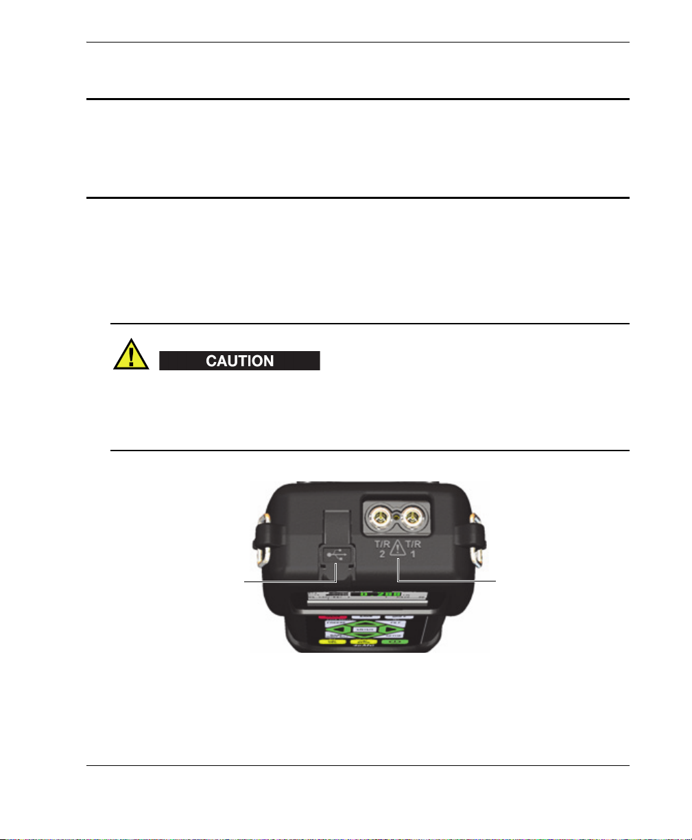
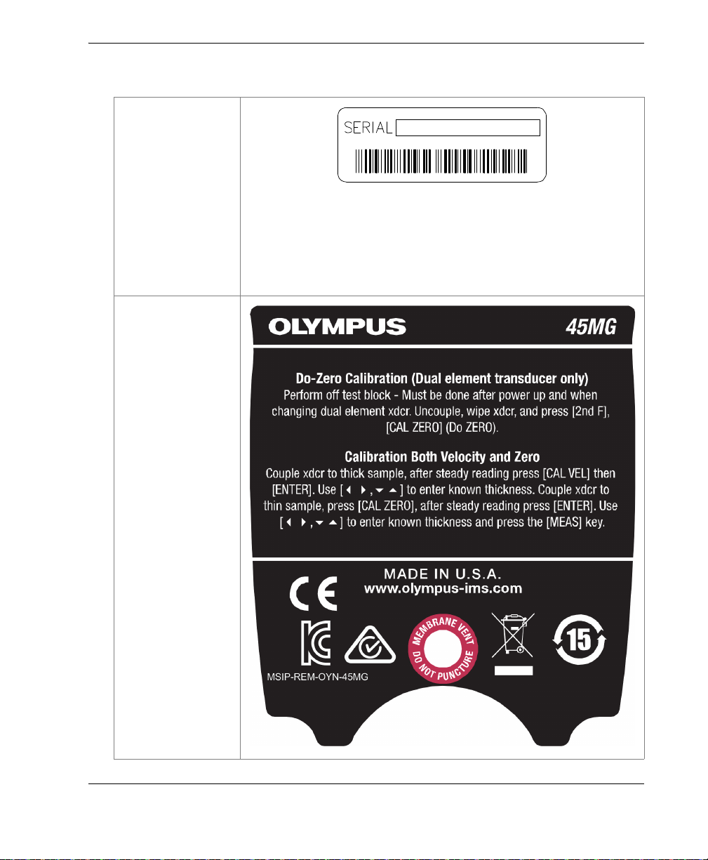
Safety-related labels and symbols are attached to the instrument at the locations
shown in Figure i-1 on page 1 and Figure i-2 on page 2. If any or all of the labels or
symbols are missing or illegible, please contact Olympus.
To avoid the risk of electric shock, do not touch the inner conductor of the T/R 1 and
T/R 2 connectors. Up to 200 V can be present on the inner conductor. The warning
symbol between the Transmit/Receive (T/R) connector markings warns of this electric
shock risk.
Figure i-1 The symbols on the top of the 45MG
Labels and Symbols
1
Page 12

DMTA-10022-01EN, Rev. C, January 2015
Instruction label
(see Table 1 on page 3)
Serial number labels
(two locations)
Labels and Symbols
2
Figure i-2 Labels attached to the back of the instrument
Page 13
Serial number
yynnnnnmm
label
Instruction label
DMTA-10022-01EN, Rev. C, January 2015
Table 1 Label contents
Where:
yy: last two digits of the production year
nnnnn: five-digit non-duplicated incrementing number
representing the n
th
production unit of this product
mm: production month
Labels and Symbols
3
Page 14
DMTA-10022-01EN, Rev. C, January 2015
Table 1 Label contents(continued)
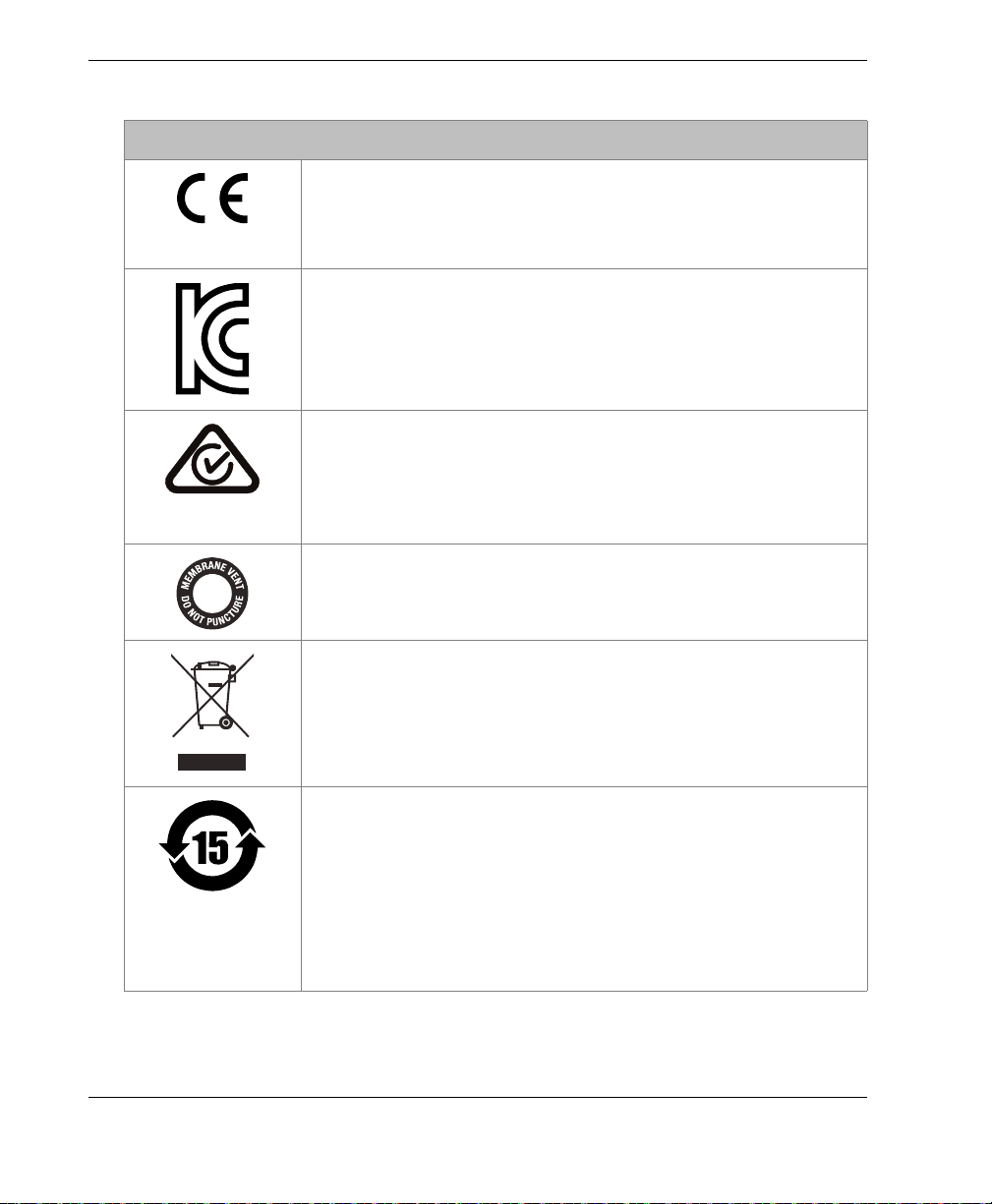
The CE marking is a declaration that this product conforms to
all the applicable directives of the European Community. See
the Declaration of Conformity for details. Contact your Olympus
representative for more information.
Seller and user shall be noticed that this equipment is suitable
for electromagnetic equipment for office work (class A) and it
can be used outside home. The MSIP code for the 45MG is the
following: MSIP-REM-OYN-45MG.
The regulatory compliance mark (RCM) label indicates that
the product complies with all applicable standards, and has
been registered with the Australian Communications and
Media Authority (ACMA) for placement on the Australian
market.
This symbol indicates the location of the membrane vent.
Content
Labels and Symbols
4
The WEEE symbol indicates that the product must not be
disposed of as unsorted municipal waste, but should be
collected separately.
The China RoHS mark indicates the product’s EnvironmentFriendly Use Period (EFUP). The EFUP is defined as the
number of years for which listed controlled substances will not
leak or chemically deteriorate while in the product. The EFUP
for the 45MG has been determined to be 15 years. Note: The
Environment-Friendly Use Period (EFUP) is not meant to be
interpreted as the period assuring functionality and product
performance.
Page 15
DMTA-10022-01EN, Rev. C, January 2015
WARNING
Important Information — Please Read Before Use
Intended Use
The 45MG instrument is designed to measure thicknesses of industrial and
commercial materials.
Do not use the 45MG for any purpose other than its intended use. It must never be
used to inspect or examine human or animal body parts.
Instruction Manual
This instruction manual contains essential information on how to use this Olympus
product safely and effectively. Before using this product, thoroughly review this
instruction manual. Use the product as instructed.
Keep this instruction manual in a safe, accessible location.
Important Information — Please Read Before Use
5
Page 16
DMTA-10022-01EN, Rev. C, January 2015
IMPORTANT
CAUTION
Some of the details of components illustrated in this manual may differ from the
components installed on your instrument. However, the operating principles remain
the same.
The 45MG documents are:
45MG Ultrasonic Thickness Gage — Getting Started (P/N: DMTA-10024-01EN
[U8778520])
A short leaflet containing essential information for quick start-up of the 45MG
instrument.
45MG Ultrasonic Thickness Gage — User’s Manual (P/N: DMTA-10022-01EN)
This document is in PDF format, and contains a detailed description of the
instrument, in addition to the setup and operating procedures for all the
instrument features. The PDF file is available on the documentation CD (P/N:
45MG-MAN-CD [U8147024]) that is shipped with the 45MG, and can also be
downloaded at www.olympus-ims.com.
GageView Interface Program — User’s Manual (P/N: 910-259-EN [U8778347])
The 45MG also works with the GageView interface program. Refer to this
document for detailed information on GageView. The document is available in
PDF format on the GageView CD, and as online help within GageView.
Instrument Compatibility
Refer to “Accessories and Replacement Parts” on page 219 for information on
accessories that are compatible with the 45MG.
Always use equipment and accessories that meet Olympus specifications. Using
incompatible equipment could cause equipment malfunction and/or damage, or
human injury.
Important Information — Please Read Before Use
6
Page 17
DMTA-10022-01EN, Rev. C, January 2015
CAUTION
Repair and Modification
Apart from the batteries, the 45MG instrument does not contain any user-serviceable
parts.
In order to prevent human injury and/or equipment damage, do not disassemble,
modify, or attempt to repair the instrument.
Safety Symbols
The following safety symbols might appear on the instrument and in the instruction
manual:
General warning symbol
This symbol is used to alert the user to potential hazards. All safety messages that
follow this symbol shall be obeyed to avoid possible harm or material damage.
High voltage warning symbol
This symbol is used to alert the user to potential electric shock hazards greater
than 1000 volts. All safety messages that follow this symbol shall be obeyed to
avoid possible harm.
Important Information — Please Read Before Use
7
Page 18
DMTA-10022-01EN, Rev. C, January 2015
DANGER
WARNING
CAUTION
IMPORTANT
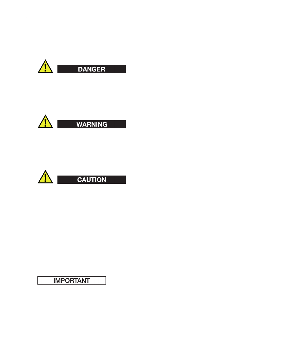
Safety Signal Words
The following safety symbols might appear in the documentation of the instrument:
The DANGER signal word indicates an imminently hazardous situation. It calls
attention to a procedure, practice, or the like, which, if not correctly performed or
adhered to, will result in death or serious personal injury. Do not proceed beyond a
DANGER signal word until the indicated conditions are fully understood and met.
The WARNING signal word indicates a potentially hazardous situation. It calls
attention to a procedure, practice, or the like, which, if not correctly performed or
adhered to, could result in death or serious personal injury. Do not proceed beyond a
WARNING signal word until the indicated conditions are fully understood and met.
The CAUTION signal word indicates a potentially hazardous situation. It calls
attention to an operating procedure, practice, or the like, which, if not correctly
performed or adhered to, may result in minor or moderate personal injury, material
damage, particularly to the product, destruction of part or all of the product, or loss of
data. Do not proceed beyond a CAUTION signal word until the indicated conditions
are fully understood and met.
Note Signal Words
The following safety symbols could appear in the documentation of the instrument:
The IMPORTANT signal word calls attention to a note that provides important
information, or information essential to the completion of a task.
Important Information — Please Read Before Use
8
Page 19
DMTA-10022-01EN, Rev. C, January 2015
NOTE
TIP
WARNING
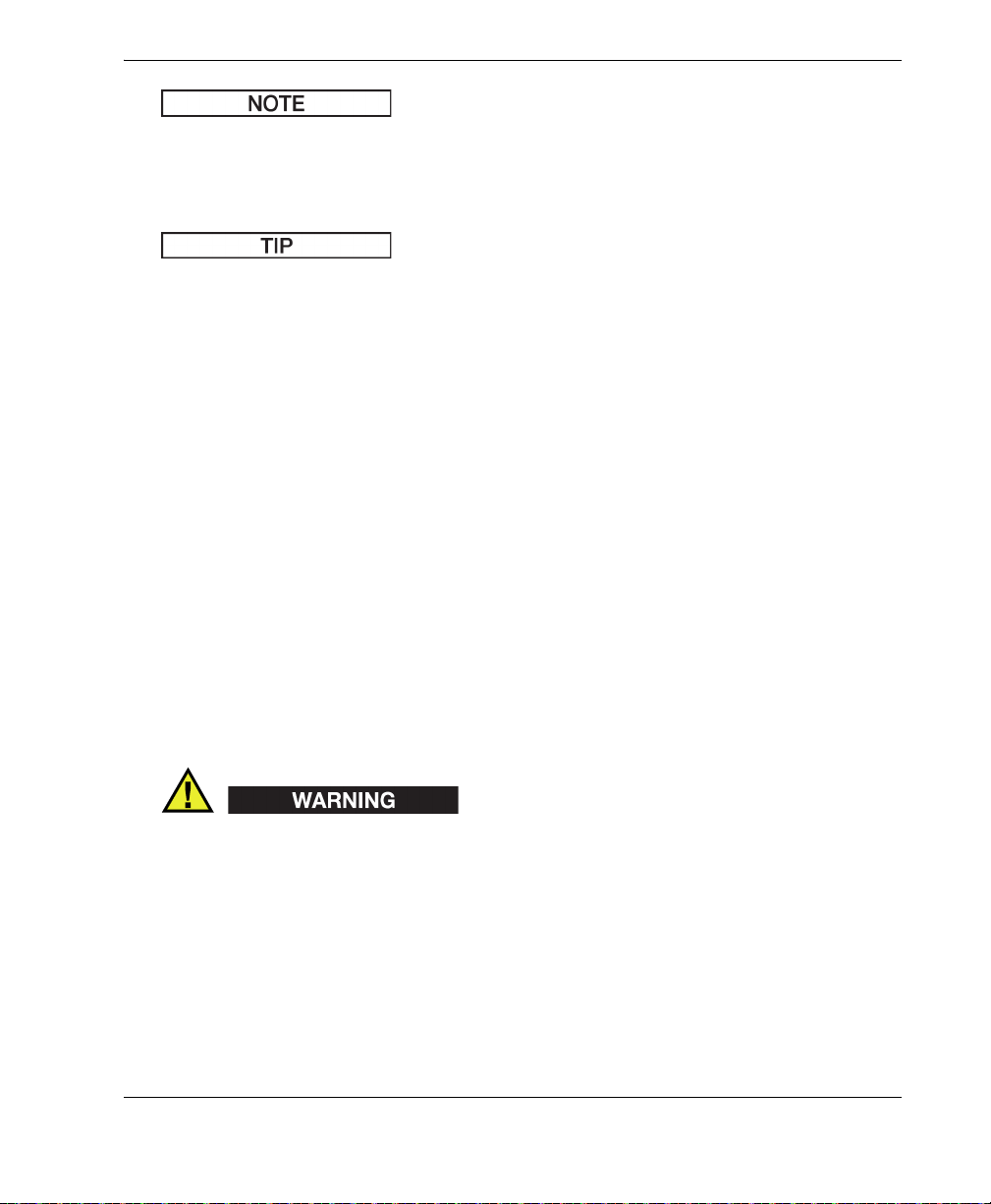
The NOTE signal word calls attention to an operating procedure, practice, or the like,
which requires special attention. A note also denotes related parenthetical
information that is useful, but not imperative.
The TIP signal word calls attention to a type of note that helps you apply the
techniques and procedures described in the manual to your specific needs, or
provides hints on how to effectively use the capabilities of the product.
Safety
This instrument has been tested according to IEC Publication 61010: Safety
Requirements for Electronic Measuring Apparatus. This instruction manual contains
warnings and safety rules that must be observed by the user to ensure safe operation
of the instrument, and maintain it in safe condition. Please read through these
operating instructions before using the instrument.
Before turning on the instrument, verify that the correct safety precautions have been
taken (see the following warnings). In addition, note the external markings on the
instrument, which are described under “Safety Symbols.”
Warnings
General Warnings
• Carefully read the instructions contained in this instruction manual prior to
turning on the instrument.
• Keep this instruction manual in a safe place for further reference.
• Follow the installation and operation procedures.
• It is imperative to respect the safety warnings on the instrument and in this
instruction manual.
Important Information — Please Read Before Use
9
Page 20
DMTA-10022-01EN, Rev. C, January 2015
CAUTION
• If the equipment is used in a manner not specified by the manufacturer, the
protection provided by the equipment could be impaired.
• Do not install substitute parts or perform any unauthorized modification to the
instrument.
• Service instructions, when applicable, are for trained service personnel. To avoid
the risk of electric shock, do not perform any work on the instrument unless
qualified to do so. For any problem or question regarding this instrument, contact
Olympus or an authorized Olympus representative.
• Do not touch the connectors directly by hand. Otherwise, a malfunction or electric
shock may result.
• Do not allow metallic or foreign objects to enter the device through connectors or
any other openings. Otherwise, a malfunction or electric shock may result.
Battery Precautions
• Before disposing of a battery, check your local laws, rules, and regulations, and
follow them accordingly.
• When lithium-metal batteries are used, transportation of the batteries is regulated
by the United Nations under the United Nations Recommendations on the
Transport of Dangerous Goods. It is expected that governments,
intergovernmental organizations, and other international organizations shall
conform to the principles laid down in these regulations, thus contributing to
worldwide harmonization in this field. These international organizations include
the International Civil Aviation organization (ICAO), the International Air
Transport Association (IATA), the International Maritime Organization (IMO), the
US Department of Transportation (USDOT), Transport Canada (TC), and others.
Please contact the transporter and confirm current regulations before
transportation of lithium-ion batteries.
• Do not open, crush, or perforate batteries; doing so could cause injury.
• Do not incinerate batteries. Keep batteries away from fire and other sources of
extreme heat. Exposing batteries to extreme heat (over 80 °C) could result in an
explosion or personal injury.
• Do not drop, hit, or otherwise abuse a battery, as doing so could expose the cell
contents, which are corrosive and explosive.
Important Information — Please Read Before Use
10
Page 21

DMTA-10022-01EN, Rev. C, January 2015
• Do not short-circuit the battery terminals. A short circuit could cause injury and
severe damage to a battery making it unusable.
• Do not expose a battery to moisture or rain; doing so could cause an electric
shock.
• Do not leave batteries in the 45MG unit during instrument storage.
Equipment Disposal
Before disposing of the 45MG, check your local laws, rules, and regulations, and
follow them accordingly.
WEEE Directive
In accordance with European Directive 2012/19/EU on Waste Electrical
and Electronic Equipment (WEEE), this symbol indicates that the
product must not be disposed of as unsorted municipal waste, but
should be collected separately. Refer to your local Olympus distributor
for return and/or collection systems available in your country.
China RoHS
China RoHS is the term used by industry generally to describe legislation
implemented by the Ministry of Information Industry (MII) in the People’s Republic
of China for the control of pollution by electronic information products (EIP).
The China RoHS mark indicates the product’s EnvironmentFriendly Use Period (EFUP). The EFUP is defined as the number of
years for which listed controlled substances will not leak or
chemically deteriorate while in the product. The EFUP for the
45MG has been determined to be 15 years.
Note: The Environment-Friendly Use Period (EFUP) is not meant
to be interpreted as the period assuring functionality and product
performance.
Important Information — Please Read Before Use 11
Page 22

DMTA-10022-01EN, Rev. C, January 2015
EMC Directive Compliance
This equipment generates and uses radio-frequency energy and, if not installed and
used properly (that is, in strict accordance with the manufacturer’s instructions), may
cause interference. The 45MG has been tested and found to comply with the limits for
an industrial device in accordance with the specifications of the EMC directive.
FCC (USA) Compliance
This device complies with Part 15 of the FCC Rules. Operation is subject to the
following two conditions:
1. This device may not cause harmful interference.
2. This device must accept any interference received, including interference that
may cause undesired operation.
Changes or modifications not expressly approved by the party responsible for
compliance could void the user’s authority to operate the equipment.
This equipment has been tested and found to comply with the limits for a Class A
digital device, pursuant to Part 15 of the FCC Rules. These limits are designed to
provide reasonable protection against harmful interference when the equipment is
operated in a commercial environment. This equipment generates, uses, and can
radiate radio frequency energy, and if not installed and used in accordance with the
instruction manual, might cause harmful interference to radio communications.
Operation of this equipment in a residential area is likely to cause harmful
interference, in which case you will be required to correct the interference at your own
expense.
ICES-001 (Canada) Compliance
This Class A digital apparatus complies with Canadian ICES-001.
Cet appareil numérique de la classe A est conforme à la norme NMB-001 du Canada.
Important Information — Please Read Before Use
12
Page 23
DMTA-10022-01EN, Rev. C, January 2015
Regulatory Information
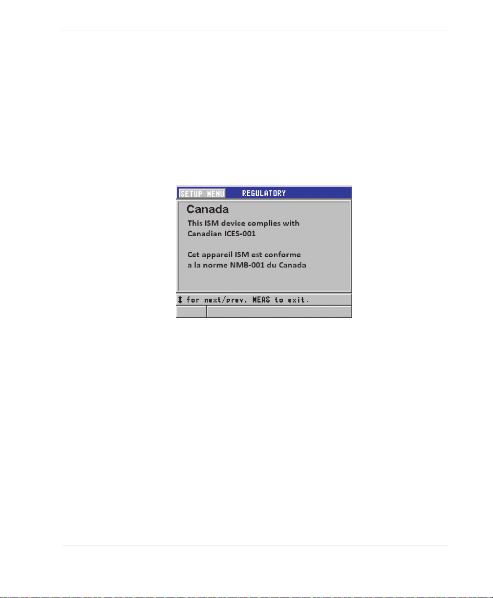
The 45MG may display a regulatory screen that lists the specific regulation with
which it complies.
To view the REGULATORY screen
1. In the measurement screen, press [SETUP], and then select SP MENU.
2. In the SP MENU (see Figure 4-2 on page 45), select REGULATORY to display the
REGULATORY screen (see Figure i-3 on page 13).
Figure i-3 The REGULATORY screen
3. Use the up and down arrow keys to scroll through the different REGULATORY
screens.
4. Press [MEAS] to return to the measurement screen.
Warranty Information
Olympus guarantees your Olympus product to be free from defects in materials and
workmanship for a specific period, and in accordance with conditions specified in the
Olympus Scientific Solutions Americas Inc. Terms and Conditions available at
http://www.olympus-ims.com/en/terms/.
Important Information — Please Read Before Use 13
Page 24

DMTA-10022-01EN, Rev. C, January 2015
The Olympus warranty only covers equipment that has been used in a proper
manner, as described in this instruction manual, and that has not been subjected to
excessive abuse, attempted unauthorized repair, or modification.
Inspect materials thoroughly on receipt for evidence of external or internal damage
that might have occurred during shipment. Immediately notify the carrier making the
delivery of any damage, because the carrier is normally liable for damage during
shipment. Retain packing materials, waybills, and other shipping documentation
needed in order to file a damage claim. After notifying the carrier, contact Olympus
for assistance with the damage claim and equipment replacement, if necessary.
This instruction manual explains the proper operation of your Olympus product. The
information contained herein is intended solely as a teaching aid, and shall not be
used in any particular application without independent testing and/or verification by
the operator or the supervisor. Such independent verification of procedures becomes
increasingly important as the criticality of the application increases. For this reason,
Olympus makes no warranty, expressed or implied, that the techniques, examples, or
procedures described herein are consistent with industry standards, nor that they
meet the requirements of any particular application.
Olympus reserves the right to modify any product without incurring the
responsibility for modifying previously manufactured products.
Technical Support
Olympus is firmly committed to providing the highest level of customer service and
product support. If you experience any difficulties when using our product, or if it
fails to operate as described in the documentation, first consult the user’s manual, and
then, if you are still in need of assistance, contact our After-Sales Service. To locate the
nearest service center, visit the Service Centers page at: http://www.olympusims.com.
Important Information — Please Read Before Use
14
Page 25
DMTA-10022-01EN, Rev. C, January 2015
IMPORTANT
Introduction
This user’s manual provides operating instruction for the 45MG ultrasonic thickness
gage. The information in this manual is organized to explain the technology, safety
details, hardware, and software. Practical measurement examples help the user
become familiar with the instrument’s capabilities.
This manual describes how to use the 45MG instrument’s advanced features,
including the use of special transducers, management of custom transducer setups,
software options, the datalogger, and communication with external devices.
The PDF file for this manual is included on the documentation CD
(P/N: 45MG-MAN-CD [U8147024]) that is shipped with the 45MG.
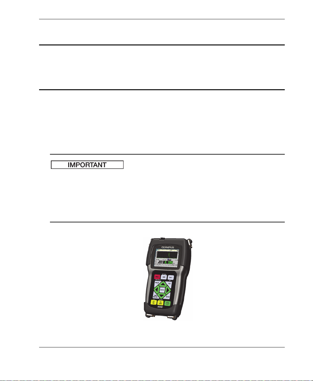
Figure i-4 The 45MG instrument
Introduction 15
Page 26

DMTA-10022-01EN, Rev. C, January 2015
16
Introduction
Page 27

DMTA-10022-01EN, Rev. C, January 2015
1. Instrument Description
This chapter describes the main features and hardware components of the 45MG
instrument.
1.1 Product Description
The 45MG by Olympus is a handheld ultrasonic thickness gage designed for a wide
variety of thickness-measurement applications. With the 45MG, you only need access
to one side of a part in order to obtain nondestructive measurements of the thickness
of corroded, pitted, scaled, granular, and other difficult materials.
The 45MG displays a thickness readout and offers an optional A-scan view for
waveform verification. The microprocessor of the 45MG continuously adjusts the
receiver setup so that every measurement is optimized for reliability, range,
sensitivity, and accuracy. An optional advanced internal datalogger can store up to
475000 thickness measurements and 20000 waveforms.
With the Single Element option, the 45MG operates with a full line of single element
transducers. Operation with dual element transducers is a standard feature.
Depending on the software options, the 45MG is capable of measuring material
thicknesses between 0.08 mm and 635.0 mm (0.003 in. and 25.0 in.). The temperature
range of measured materials may vary between
depending on the material characteristics, the transducer, and the measurement
mode.
−20 °C and 500 °C (−4°F and 932°F),
Basic features
• Measurement-related status flags and alarms
• Quarter VGA color transflective LED back-lite display
Instrument Description 17
Page 28

DMTA-10022-01EN, Rev. C, January 2015
• Automatic probe recognition for the standard D79X and MTD705 series
transducers
• Warning against calibration doubling (for dual element transducers)
• Calibration for unknown material sound velocity and/or transducer zero
• Fast scan mode with 20 readings per second
• Hold or blank thickness display during loss-of-signal (LOS) conditions
• Hold minimum and maximum functions
• Differential thickness display relative to the set point in absolute values or
percentage ratios
• Selection of password-protected lockout functions
• Selectable resolution: low of 0.1 mm (0.01 in.), standard of 0.01 mm (0.001 in.), or
high (optional) of 0.001 mm (0.0001 in.); [option not available for all transducers]
Optional features
• Single element transducers
• Echo-to-Echo and THRU-COAT measurements
• High Penetration software for low-frequency single element transducers
• A-scan or waveform display
— Real-time A-scan waveform display for verification of critical measurements
— Manual freeze mode with post processing
— Manual zoom and range control of waveform display
— Auto hold on loss of signal (LOS) and auto zoom (measured echo centering)
— Extended blank
— Blank after first received echo in Echo-to-Echo mode
— Receiver gain readout
— Ability to capture and display waveform associated with minimum thickness
during scanned measurements
— Display of stored and downloaded waveforms (Datalogger option only)
— Manual gain adjustment in 1-dB steps
• Internal datalogger functions
— Internal data storage and possibility to export data to a removable microSD
memory card
— Capacity to store 475000 fully-documented thickness readings or
20000 waveforms with thickness readings
18
Chapter 1
Page 29
DMTA-10022-01EN, Rev. C, January 2015
CAUTION
— Database enhancements include 32-character file naming and 20-character ID
naming
— Automatic ID number increments following a preset sequence, or manual ID
numbering using the keypad
— Save reading/waveform to an ID number
— Ability to simultaneously display ID number and stored reference thickness
while displaying active thickness and waveform
— Five file formats available
— Erase selected data or all stored data
— Standard USB directional communication
1.2 Environmental Ratings
The 45MG is a rugged and durable instrument that can be used in harsh
environments. The 45MG was designed to meet the requirement of the IP67 rating
(Ingress Protection rating).
Olympus cannot guarantee any level of ingress protection rating once the instrument
seals have been manipulated. You must use sound judgment, and take proper
precautions before exposing the instrument to harsh environments.
To maintain the original level of ingress protection, you are responsible for the proper
care of all routinely exposed membrane seals. Additionally, you are responsible for
returning the instrument to an authorized Olympus service center on an annual basis
to ensure that the instrument seals are properly maintained.
1.3 Instrument Hardware Components
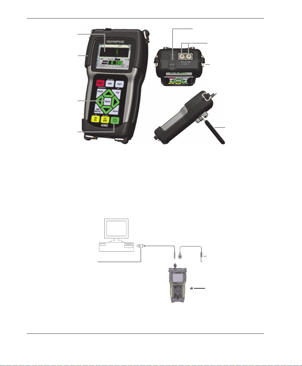
The 45MG front panel features a color display and a keypad. The instrument comes
with a wrist strap. An optional protective rubber boot includes a dust flap seal for the
USB communication connector, strap rings at the four corners, and a stand at the back
of the instrument (see Figure 1-1 on page 20).
Instrument Description 19
Page 30
DMTA-10022-01EN, Rev. C, January 2015
Protective rubber
boot
Stand
Strap rings (at the
four corners)
Color display
Keypad
I/O door protecting USB
connector
Transducer
connectors
Power key
USB connector
Transducer
microSD memory
card
Figure 1-1 The 45MG hardware components — Front, top, and side views
1.4 Connectors
20
Figure 1-2 on page 20 illustrates the possible connections between the 45MG and
external devices.
Figure 1-2 The 45MG connections
Chapter 1
Page 31
DMTA-10022-01EN, Rev. C, January 2015
USB communication
connector
Transmit/Receive transducer
connector 2
Transmit/Receive
transducer connector 1
microSD memory card
slot
Battery door
Battery compartment
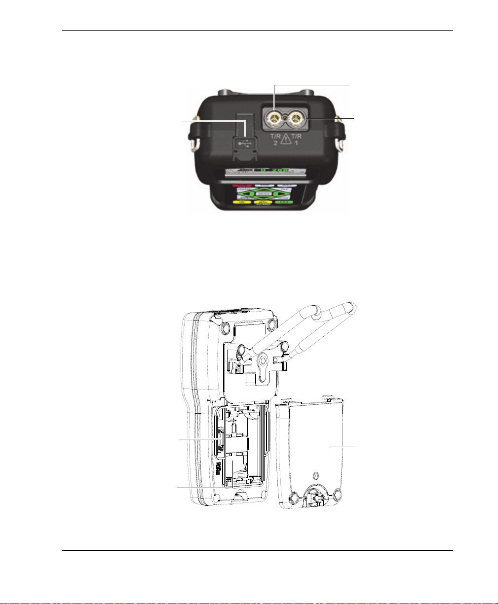
The USB and Transmit/Receive transducer connectors are located on the top of the
45MG (see Figure 1-3 on page 21).
Figure 1-3 The top end connectors
The external microSD memory card slot is located behind the battery door (see
Figure 1-4 on page 21).
Figure 1-4 The microSD connector behind the battery door
Instrument Description 21
Page 32
DMTA-10022-01EN, Rev. C, January 2015
English keypad International keypad
1.5 Keypad Functions
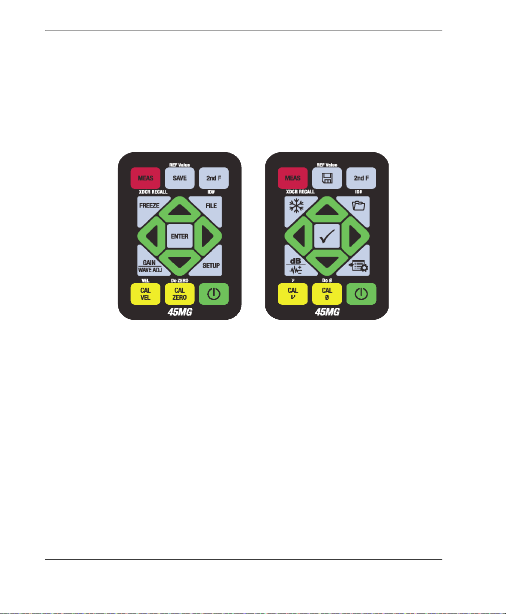
The 45MG comes either with the English or the international keypad (see Figure 1-5
on page 22). The functions are the same for both keypads. On the international
keypad, the text labels on many keys are replaced by pictograms. In this document,
keypad keys are referred to using the English label in bold and within brackets (ex.:
[MEAS]).
Figure 1-5 The 45MG keypads
Each key is labelled according to its primary function. The area immediately above
certain keys contains a secondary key function that can be activated by first pressing
[2nd F]. Throughout this document, references to a secondary function are written as
follows: [2nd F], [Primary] (Secondary). For example, the instruction to activate the
REF Value function is written as follows: “Press [2nd F], [SAVE] (REF Value)”.
The [], [], [], and [] keys, along with the [ENTER] key, are used to select menu
items or screen parameters, and to change parameter values. Use the [MEAS] key at
any time to return to the measurement screen. The yellow keys are related to
calibration.
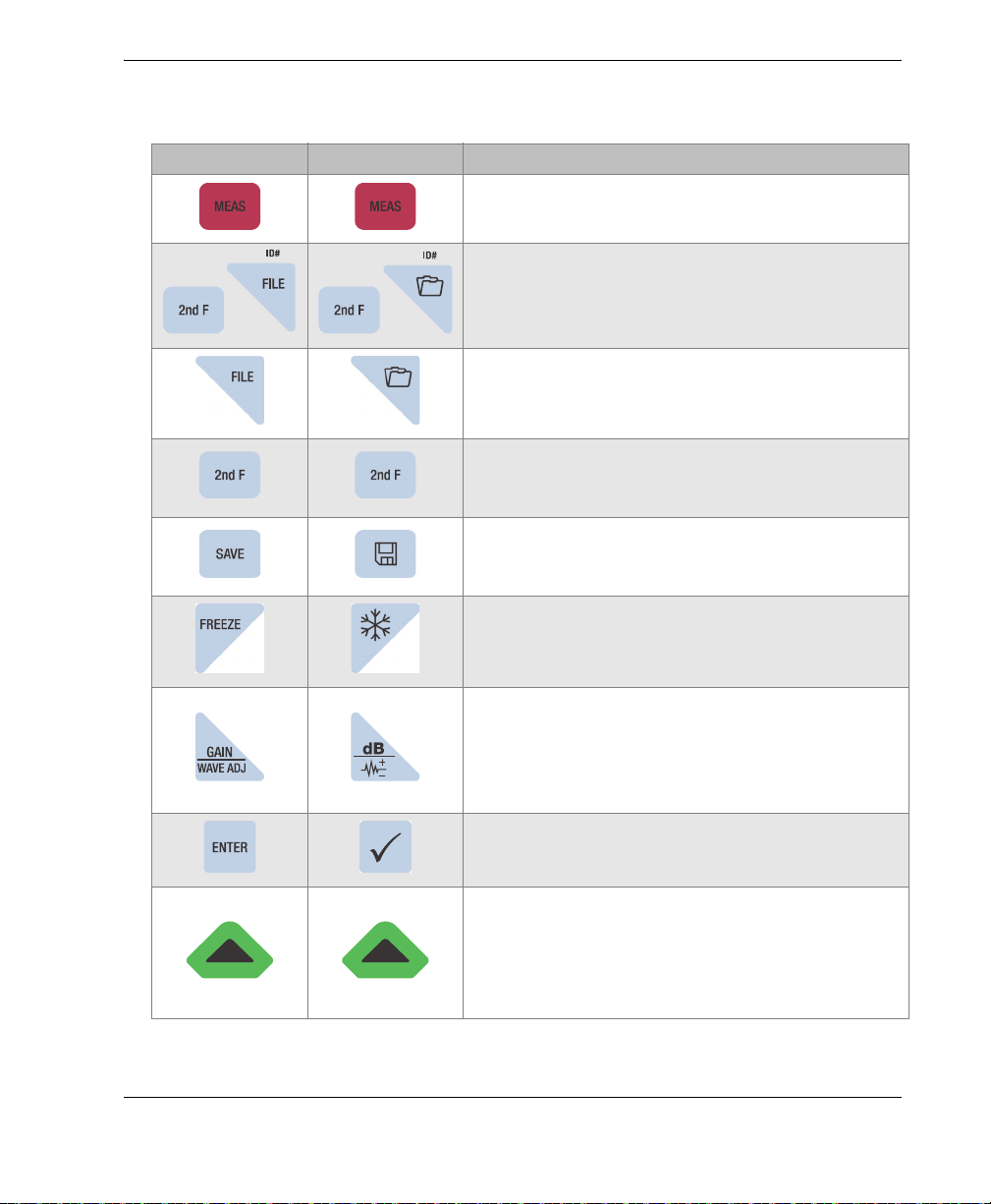
Table 2 on page 23 lists the key functions available on the 45MG keypad. Many
functions are optional, and may not be available depending on which software
options have been purchased.
Chapter 1
22
Page 33
DMTA-10022-01EN, Rev. C, January 2015
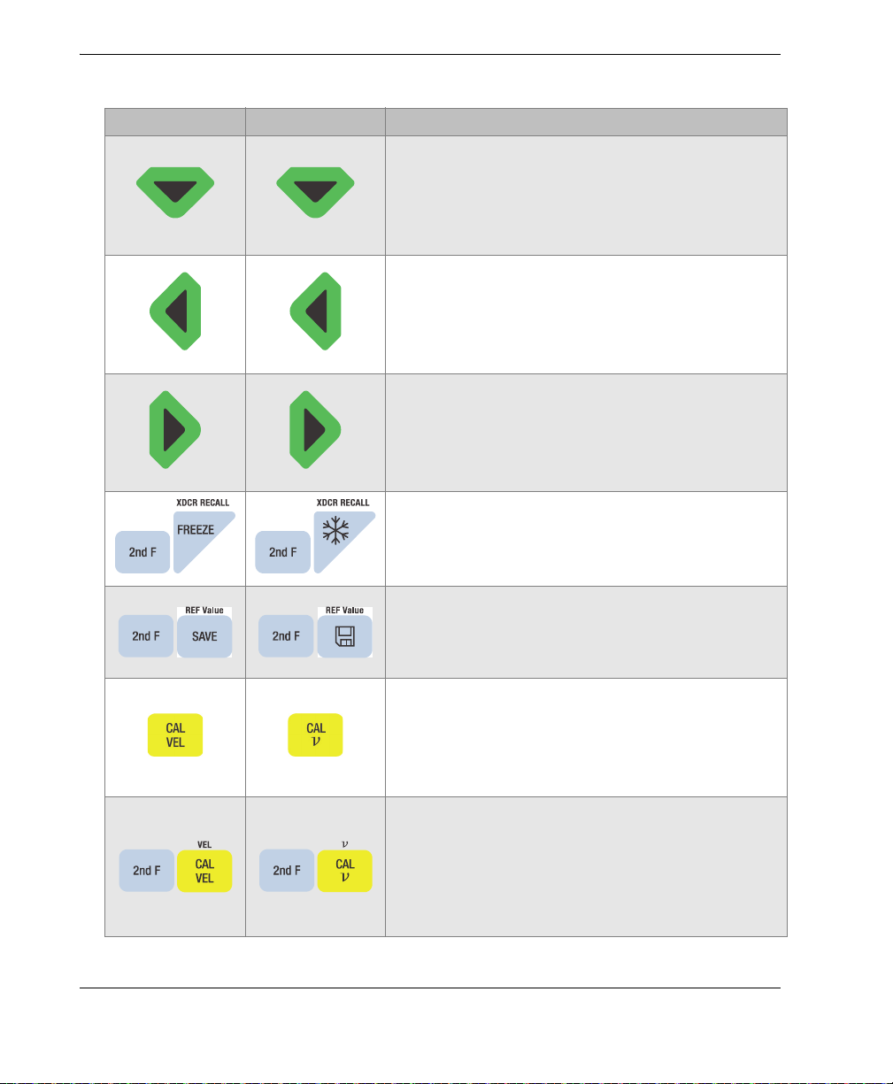
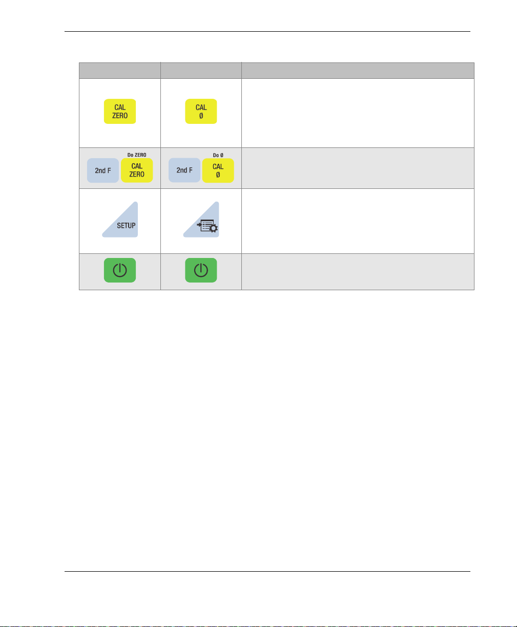
Table 2 Keypad functions
English International Functions
Measurement — Completes the current operation
and returns to the measurement screen.
Identification number — Accesses several
functions related to the ID numbers for the
thickness-measurement location.
File — Opens the file menu to access file
commands (open, review, create, copy, edit,
delete, send, import, export, memory, and report).
Secondary function — Needs to be pressed prior
to a key to activate the secondary function of the
key.
Save — Stores a measurement and optionally the
corresponding waveform in the datalogger at the
current ID number.
Freeze — Causes the displayed screen or
waveform to immediately hold until the key is
pressed again.
Gain — Initiates the adjustment of the gain value
when using dual element transducers.
Wave adjustment — Toggles the display of a
selectable waveform parameter with an editable
value.
Enter — Selects a highlighted item, or accepts an
entered value.
Up arrow
• In a screen or a list, moves to the previous
element.
• For some parameters, a numerical entry
increases the value.
Instrument Description 23
Page 34
DMTA-10022-01EN, Rev. C, January 2015
Table 2 Keypad functions (continued)
English International Functions
Down arrow
• In a screen or a list, moves to the next
element.
• For some parameters, a numerical entry
decreases the value.
Left arrow
• Selects the previous available value for the
selected parameter.
• In text edit mode, moves the cursor one
character position to the left.
Right arrow
• Selects the next available value for the
selected parameter.
• In text edit mode, moves the cursor one
character position to the right.
Transducer recall — Recalls default or custom
transducer (XDCR) setups.
24
Reference value — For some functions (ex.:
differential mode, or thickness for velocity mode),
opens a screen allowing you to enter a reference
value.
Velocity calibration
• Switches to the semiautomatic step block
calibration mode.
• With the traditional text edit mode only,
deletes the character at the cursor position.
Veloci ty
• Opens a screen allowing you to view and
manually change the sound velocity.
• In THRU-COAT mode, pressing the keys a
second time allows you to view/adjust the
velocity for the coating.
Chapter 1
Page 35
DMTA-10022-01EN, Rev. C, January 2015
Table 2 Keypad functions (continued)
English International Functions
Zero calibration
• Compensates for transducer zero, or enables
the step block zero calibration.
• With the traditional text edit mode only,
inserts a character at the cursor position.
Do ZERO — Compensates for transducer delay
for dual element transducers and the M2008
transducer.
Setup menu — Provides access to instrument
parameters (measurement, system, display, alarm,
differential mode, communication, B-scan, DB
grid, password, locks, resets, and SP [special]
menu).
On/Off — Turns the instrument power on or off.
Instrument Description 25
Page 36

DMTA-10022-01EN, Rev. C, January 2015
26
Chapter 1
Page 37
DMTA-10022-01EN, Rev. C, January 2015
Battery power indicator
(shown at 100 % level)
microSD card indicator
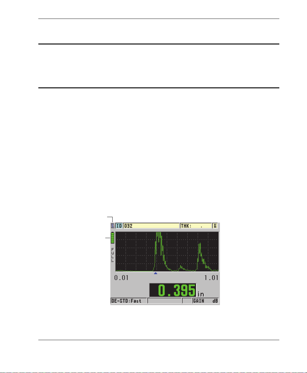
2. Powering the 45MG
This chapter describes how to power the 45MG using different power options.
2.1 Power Indicator
The power indicator is always present on the left side of the screen, and it shows the
type of power source used. The 45MG can be powered by three AA-size batteries, by a
computer through its USB connector, or by a commercially available 5-volt USB
power supply.
When using batteries, the vertical green bar in the power indicator indicates the
remaining battery level (see Figure 2-1 on page 27). Each graduation mark represents
20 % of the level.
Figure 2-1 The power indicator when using batteries
Powering the 45MG 27
Page 38
DMTA-10022-01EN, Rev. C, January 2015
45MG powered by computer
45MG powered by USB power supply
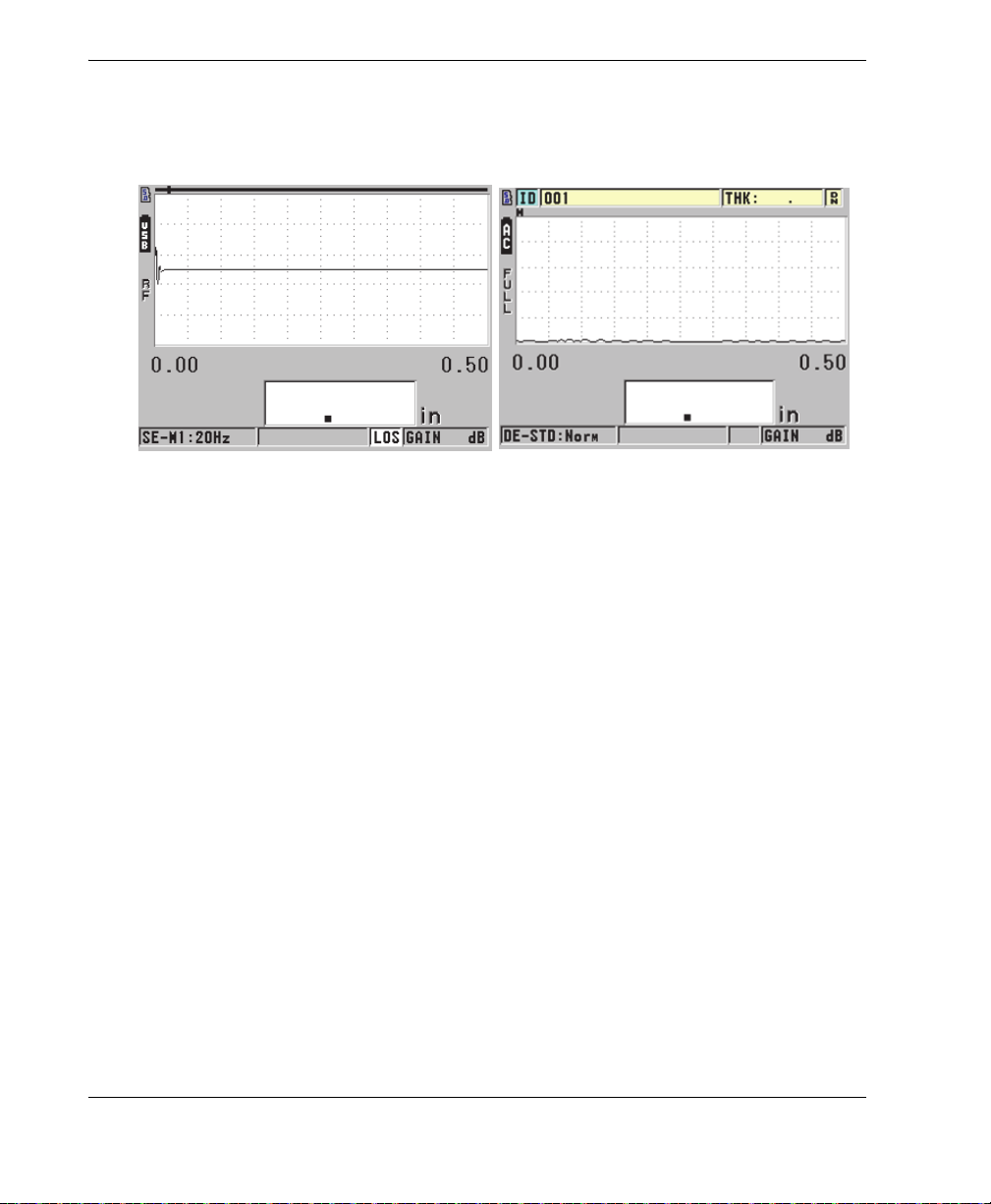
When using a computer or a 5-volt USB power supply, the power indicator is
represented by the USB logo, or by the AC logo, respectively (see Figure 2-2 on
page 28).
Figure 2-2 The power indicator when using a computer or an AC power supply
2.2 Battery Power
The 45MG comes with three AA-size alkaline batteries.
The 45MG can also be operated using three AA-size nickel-metal hydride (NiMH)
rechargeable batteries, or three nonrechargable AA-size lithium batteries. The 45MG
does not recharge NiMH batteries. To recharge the batteries, you must use a
commercially available external battery charger (not included).
2.2.1 Battery Operating Time
The battery operating time depends on the type of batteries being used, the age of the
batteries, and the instrument settings. To provide realistic battery operating times, the
45MG has been tested with mid-level operating parameters (update rate set to 4 Hz
and display brightness set to 20 %).
The nominal battery operating times for new batteries are:
• Alkaline: 20–21 hours (nonrechargeable)
• NiMH: 22–23 hours (externally recharged)
Chapter 2
28
Page 39
DMTA-10022-01EN, Rev. C, January 2015
NOTE
Battery compartment
door
Batteries
Battery compartment
gasket
Battery compartment
door lock
• Lithium: 35–36 hours (nonrechargeable)
2.2.2 Battery Level and Storage
When the batteries are full (100 % level), the battery power indicator will show full
bars.
Battery Storage Instructions
• Store batteries in a cool, dry environment.
• Avoid long-term storage under sunlight, or in other excessively hot places such as
the trunk of an automobile.
2.2.3 Replacing the Batteries
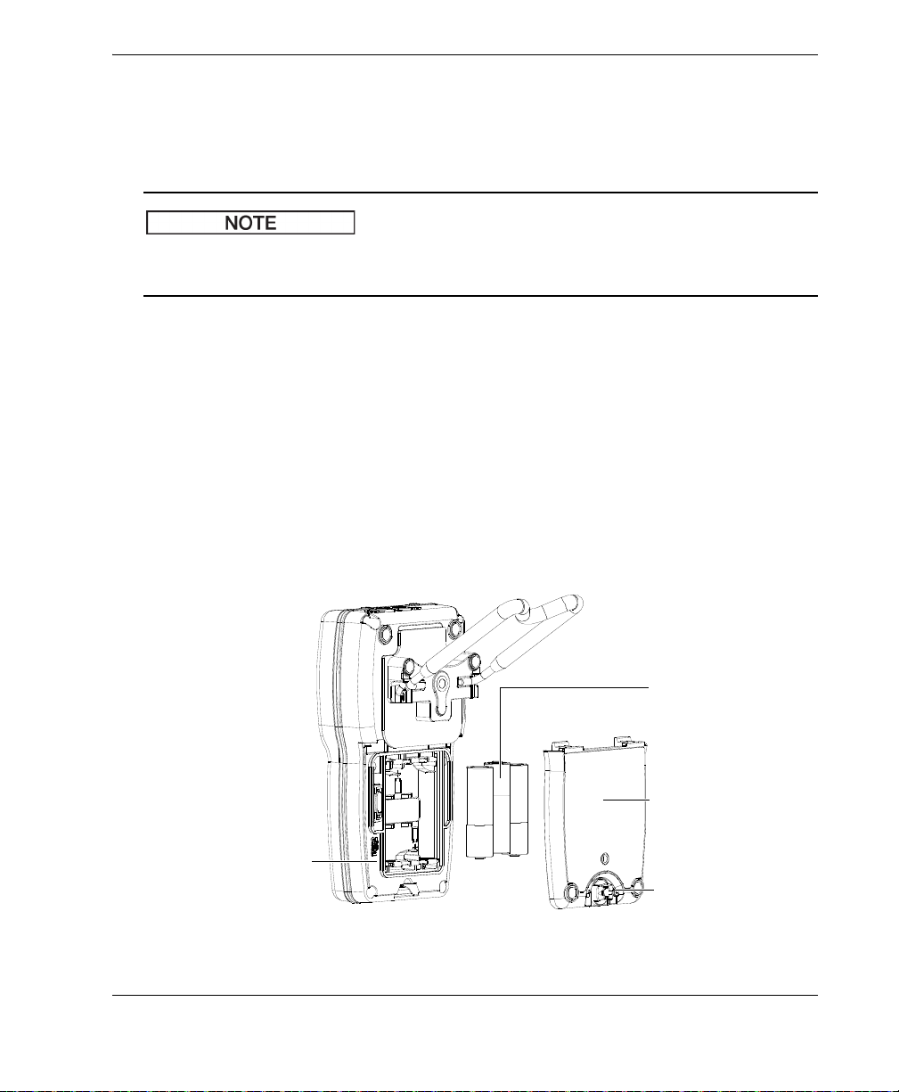
The batteries are located in a compartment that is accessible from the back of the
45MG (see Figure 2-3 on page 29).
Figure 2-3 Opening the battery compartment
Powering the 45MG 29
Page 40
DMTA-10022-01EN, Rev. C, January 2015
CAUTION
Do not replace the batteries while the instrument is on. Dispose of used batteries
promptly. Keep batteries out of reach of children. The batteries used in this device
may present a risk of fire or chemical burn if mistreated. Do not disassemble, heat
above 50 °C, or incinerate the batteries.
To replace the batteries
1. Ensure that the power to the 45MG is turned off.
2. Disconnect any other cables connected to the 45MG.
3. Remove the optional protective rubber boot, if installed.
4. Turn the battery door lock half a turn counterclockwise to the unlock position.
5. Remove the battery compartment cover.
6. Remove the batteries.
7. Insert three new batteries in the battery compartment, making sure that you
observe the correct polarity.
8. Ensure that the gasket inside the battery compartment cover is clean and in good
condition.
9. Reinstall the battery compartment cover on the back of the instrument, push
down on the bottom of the battery door, and then turn the battery door lock half a
turn clockwise to the lock position.
10. Reinstall the optional protective rubber boot, if required.
11. Press to turn on the 45MG instrument.
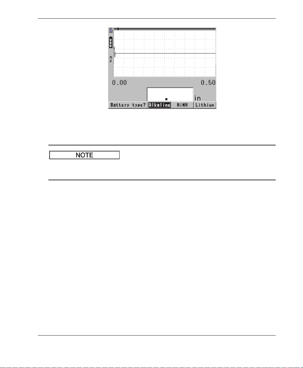
12. To answer the question appearing at the bottom of the screen (see Figure 2-4 on
page 31):
Select Alkaline when using three AA-size alkaline batteries.
OR
Select NiMH when using three AA-size nickel-metal hydride (NiMH
batteries).
OR
Select Lithium when using three AA-size lithium batteries.
Chapter 2
30
Page 41
DMTA-10022-01EN, Rev. C, January 2015
NOTE
Figure 2-4 Selecting the battery type
When replacing batteries, make sure that they are full in order to ensure the accuracy
of the estimated remaining battery life shown by the power indicator.
Powering the 45MG 31
Page 42

DMTA-10022-01EN, Rev. C, January 2015
32
Chapter 2
Page 43
DMTA-10022-01EN, Rev. C, January 2015
Mode and update rate
Battery power indicator
Gain level
ID bar
(with Datalogger option)
Measurement units
Thickness value
Download indicator
3. Software User Interface Elements
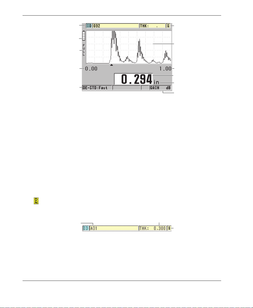
The following sections describe the main elements of the 45MG software screens and
menus.
3.1 Measurement Screen
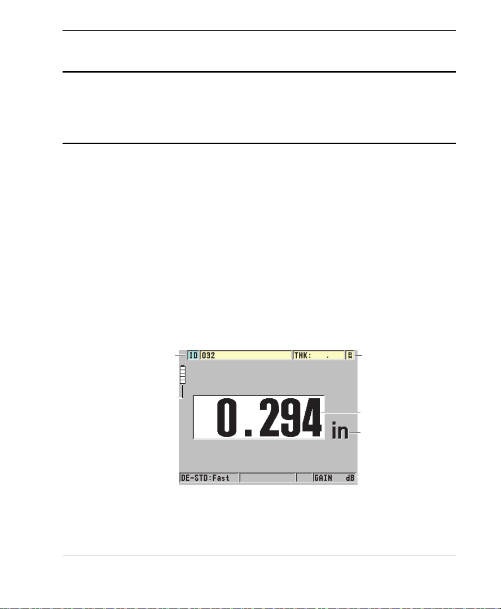
The 45MG has two different main measurement screens:
The first screen (see Figure 3-1 on page 33) displays when the Waveform option is
not activated, or when the Waveform option feature is turned off.
OR
The second screen (see Figure 3-2 on page 34) displays when the Waveform
option is purchased and turned on.
Figure 3-1 The measurement screen — No waveform enabled
Software User Interface Elements 33
Page 44
DMTA-10022-01EN, Rev. C, January 2015
Rectification indicator
Mode and update rate
Battery power indicator
Gain level
Optional waveform
display (A-scan)
Range
Thickness value
ID bar
(with Datalogger option)
Measurement units
Delay
Download indicator
Previously stored thickness value
DN flag indicating a
previous thickness
ID number
(with Datalogger option)
Figure 3-2 The measurement screen — Waveform option enabled
The measurement screen is the main screen of the 45MG software. From anywhere in
the 45MG software, simply press [MEAS] to return to the measurement screen. The
power indicator is always present on the left side of the 45MG screen (see “Power
Indicator” on page 27 for details).
The optional waveform trace, called the A-scan, allows a skilled operator to verify that
the signal used to make a thickness measurement is the correct back-wall echo, and
not noise, material anomaly, or the second multiple echo. The A-scan also enables you
to observe indications that may be too small to be measured by the instrument.
The ID bar (available with the Datalogger option), located at the top of the
measurement screen, contains the ID for the actual thickness-measurement location
and the previously stored value (see Figure 3-3 on page 34). The download indicator
( ) appears when the previously stored thickness measurement comes from a file
rather than a newly acquired value.
Chapter 3
34
Figure 3-3 The ID bar
Page 45
DMTA-10022-01EN, Rev. C, January 2015
Freeze indicator
Mode indicator (min/max)
and value
Alarm level indicator
Gain level
The indicator ( ) of the optional external microSD memory card appears at the top
left side of the screen when a microSD memory card is inserted in its slot, which is
located in the battery compartment (see Figure 1-4 on page 21). The 45MG will
recognize an external microSD memory card, with a maximum capacity of 2 GB, upon
instrument start-up.
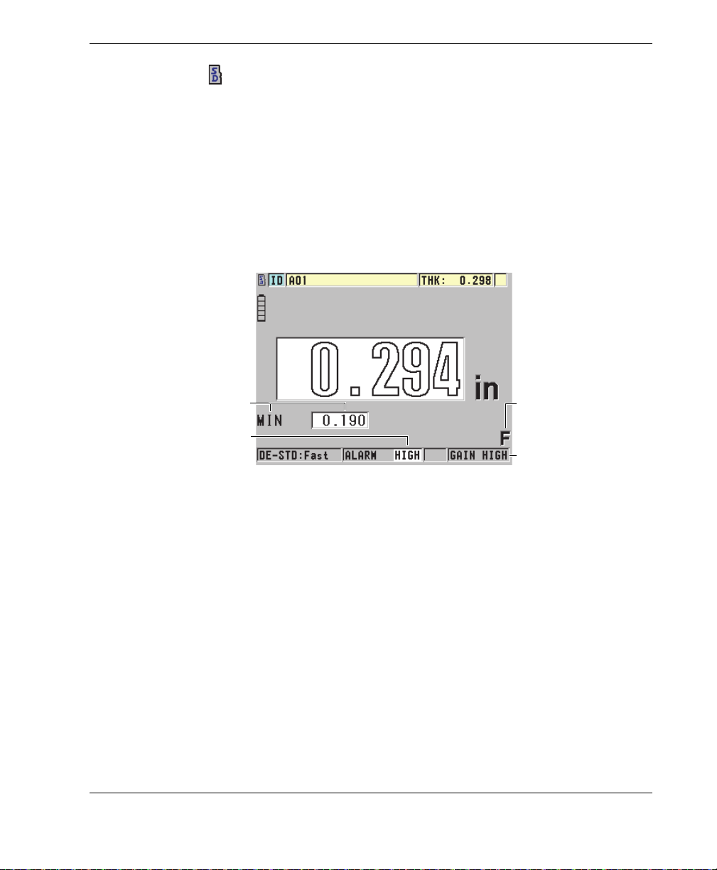
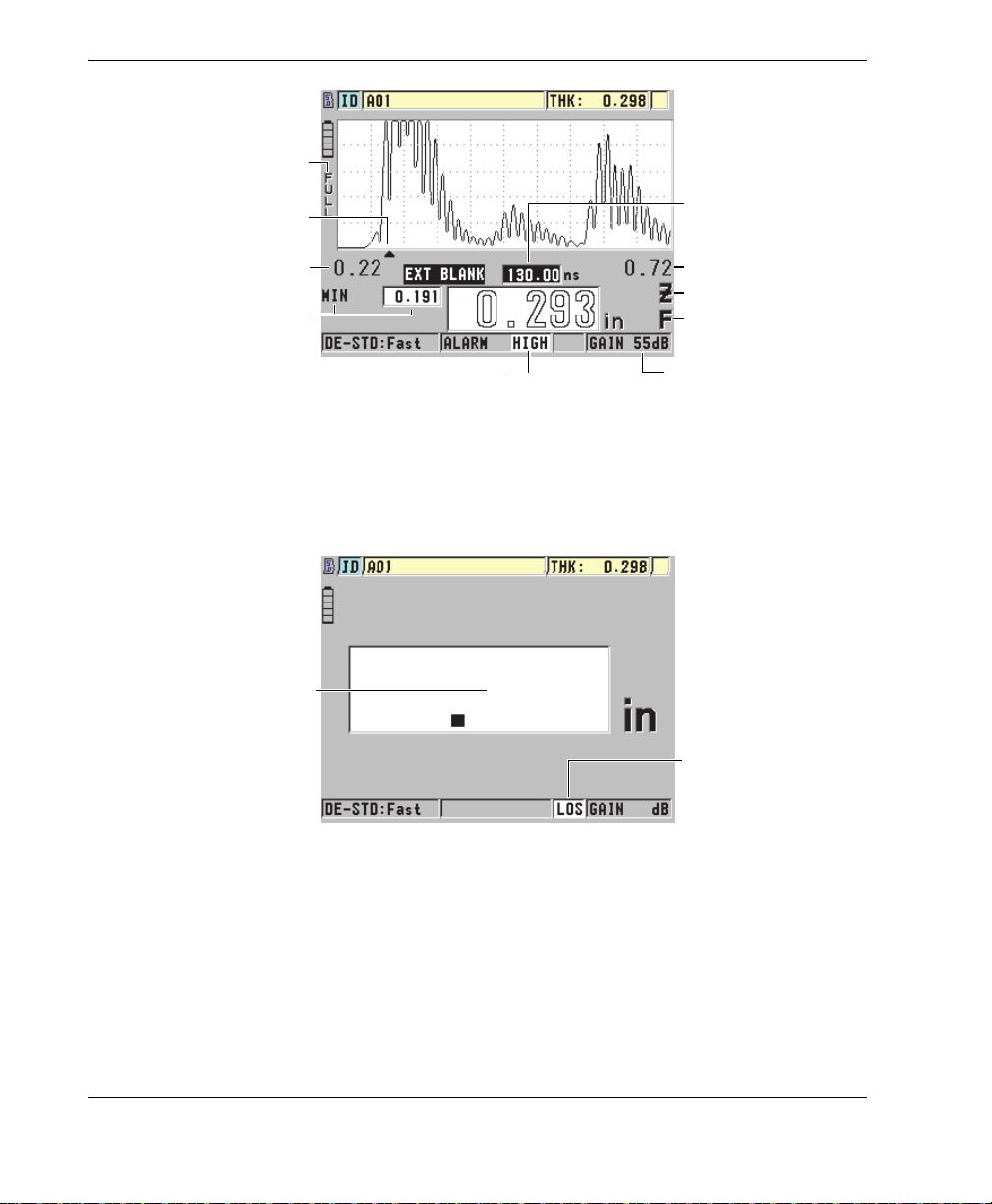
Depending on the context, and on the available functions and options, various
indicators and numeric values appear around the waveform display and around the
main measurement value (see Figure 3-4 on page 35 and Figure 3-5 on page 36). A
help text bar will appear upon certain key presses in order to indicate the keys that
can be used to navigate and make selections in the menu structure.
Figure 3-4 Other elements — No Waveform option enabled
Software User Interface Elements 35
Page 46
DMTA-10022-01EN, Rev. C, January 2015
Zoom indicator
Rectification indicator
Echo detection marker
Delay value
Mode indicator (min/max)
and value
Freeze indicator
Alarm indicator
Gain
Range value
[WAVE ADJ] parameter
Loss-of-signal (LOS)
indicator (or SAT in the
case of saturation)
No thickness value found
Figure 3-5 Other elements — Waveform option enabled
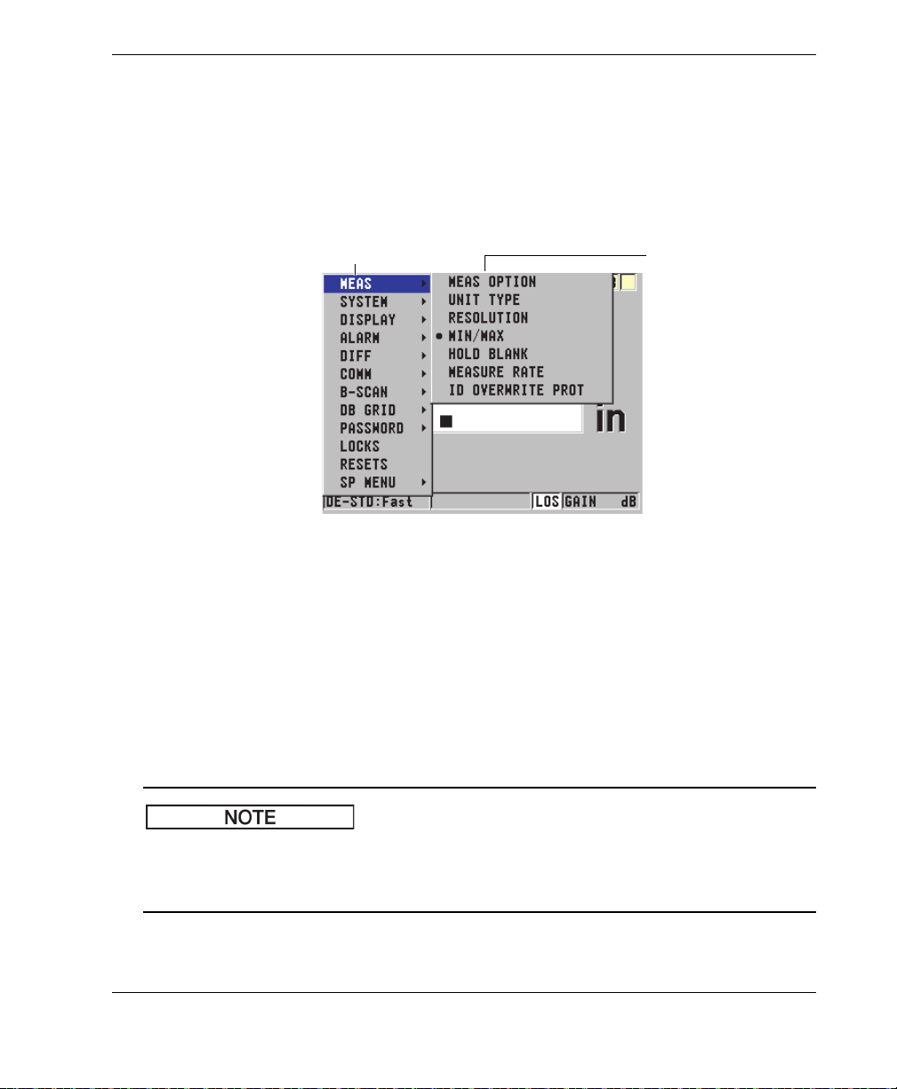
The loss of signal (LOS) appears and the thickness value is cleared when the 45MG no
longer detects ultrasonic echoes (see Figure 3-6 on page 36).
In the rare case that the returning signal from the transducer is beyond the upper
receiver-voltage limit, the LOS indicator will be replaced by the SAT flag for
indication of saturation. This situation can normally be corrected by lowering the
pulser voltage.
36
Chapter 3
Figure 3-6 The loss-of-signal (LOS) indicator
Page 47
DMTA-10022-01EN, Rev. C, January 2015
Menu Submenu for the
highlighted menu
command
NOTE
3.2 Menus and Submenus
The 45MG displays menus and submenus when you press certain front panel keys.
The menu appears at the top-left corner of the screen (see Figure 3-7 on page 37). If
applicable, a submenu conveniently showing the parameters available for the
highlighted menu command also appears.
Figure 3-7 Menu and submenu example
To select a menu or a submenu command
1. Press [SETUP] or [FILE] (with the Datalogger option) to display a menu.
2. Use the [] and [] keys to highlight the desired menu command.
3. If applicable and needed, use the [] key to highlight the submenu, and then use
the [] and [] keys to highlight the desired submenu command.
4. Press [ENTER] to select the highlighted menu or submenu command.
In the remainder of this document, the above procedure is summarized by a simple
instruction to select a specific menu or submenu command. For example: “In the
menu, select MEAS.”
Software User Interface Elements 37
Page 48
DMTA-10022-01EN, Rev. C, January 2015
Help text bars
Parameters
Title bar
Menu from which the
screen is accessed
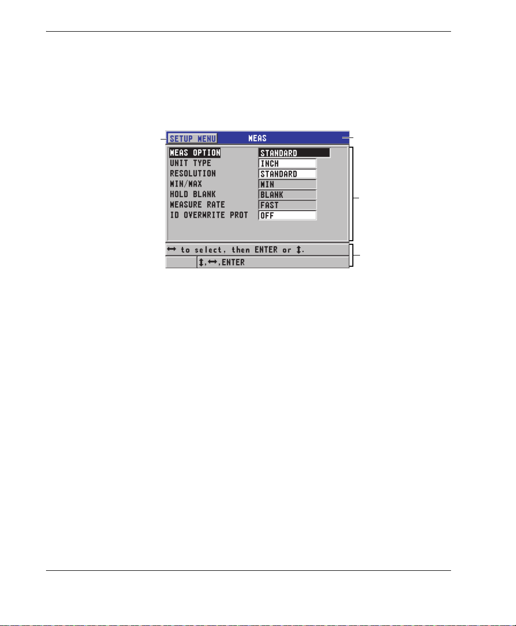
3.3 Parameter Screens
The 45MG parameters are logically grouped in parameter screens that can be accessed
using front panel keys or menu commands. Figure 3-8 on page 38 shows the MEAS
parameter screen as an example.
Figure 3-8 Parameter screen example
The title bar, located at the top of the parameter screen, indicates the parameter
subject. When you access a parameter screen from a menu, a menu button appears on
the left side of the title bar. This menu button can be used to easily return to the
original menu. One or two help text bars appear at the bottom of the screen to indicate
the keys required to select a parameter and edit its value.
To select a parameter and edit its value
1. Use the [] and [] keys to highlight the desired parameter.
2. For parameters with predefined values, use the [] and [] keys to select the
desired value.
3. In parameter screens containing lists or alphanumeric parameters:
• In a list, use the [] and [] keys to highlight the desired list item.
38
• For an alphanumeric parameter, use the [] and [] keys to enter the desired
characters (see “Selecting the Text Edit Mode” on page 39 for details).
•Press [2nd F], [] or [2nd F], [] to leave a list or alphanumeric parameter,
and proceed to the next or previous screen element.
4. To exit the parameter screen, press [MEAS] to return to the measurement screen.
Chapter 3
Page 49
DMTA-10022-01EN, Rev. C, January 2015
NOTE
In the remainder of this document, the above procedure is summarized by the simple
instruction to select a specific parameter or list, and its value. For example:
“In the MEAS screen, set MEAS MODE to THICKNESS.”
3.4 Selecting the Text Edit Mode
The 45MG offers two methods of editing the value of alphanumeric parameters.
Either the virtual keyboard or traditional method can be used. The virtual keyboard
appears on the screen to display all the available characters that can be used (see
“Editing Text Parameters Using the Virtual Keyboard” on page 39 for details). With
the traditional method, you must select each character from a hidden list of standard
sorted letters, numbers, and special characters (see “Editing Text Parameters Using
the Traditional Method” on page 41 for details).
To select the text edit mode
1. In the measurement screen, press [SETUP], and then select SYSTEM.
2. In the SYSTEM screen, highlight TEXT EDIT MODE, and then select the desired
mode (VIRTUAL or TRADITIONAL).
3. Press [MEAS] to return to the measurement screen.
3.4.1 Editing Text Parameters Using the Virtual Keyboard
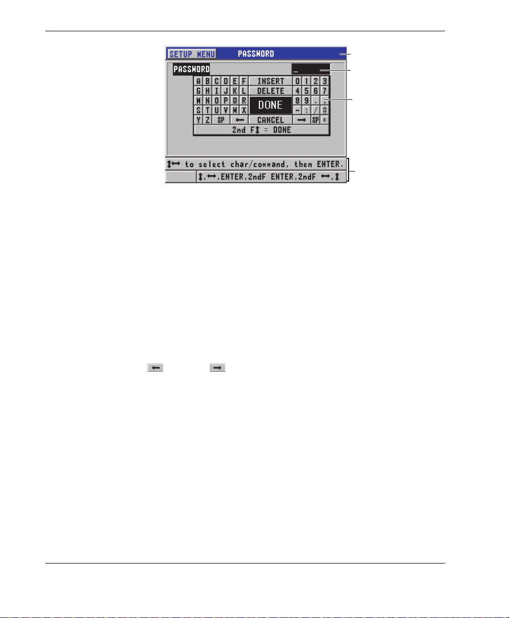
When TEXT EDIT MODE is set to VIRTUAL, the virtual keyboard appears when an
alphanumeric parameter is selected (see Figure 3-9 on page 40).
Software User Interface Elements 39
Page 50
DMTA-10022-01EN, Rev. C, January 2015
Help text bars
Title bar
Virtual keyboard
Parameter value text
box
Figure 3-9 Example of the virtual keyboard
To edit an alphanumeric parameter value using the virtual keyboard
1. Select an alphanumeric parameter.
The virtual keyboard appears.
2. Use the [], [], [], and [] keys to highlight the character that you wish to
enter, and then press [ENTER].
The selected character appears in the parameter value text box, and the cursor
moves to the next character position.
3. Repeat the previous step to enter other characters.
4. If you need to move the position of the cursor in the value text box, highlight
either the left ( ) or right ( ) arrow button on the virtual keyboard, and then
press [ENTER].
The cursor moves by one character position.
5. When you need to delete a character:
a) Move the cursor to the character you wish to delete.
b) On the virtual keyboard, highlight DELETE, and then press [ENTER].
6. When you need to insert a character:
a) Move the cursor to the character in front of which you wish to insert a
character.
b) On the virtual keyboard, highlight INSERT, and then press [ENTER].
c) Enter the desired character in the inserted space.
7. If you want to cancel the editing operation and return to the original parameter
value, highlight CANCEL on the virtual keyboard, and then press [ENTER].
40
Chapter 3
Page 51
DMTA-10022-01EN, Rev. C, January 2015
NOTE
[]
Cycling begins at “A” when the
original character is a letter.
Cycling begins at “0” when the
original character is a digit.
[]
8. To complete editing of the parameter value, highlight DONE on the virtual
keyboard, and then press [ENTER].
When editing a multiple line parameter value, highlight DONE and press [ENTER] to
move the cursor to the next line. You can also press [2nd F], [] to accept the text and
move the cursor to the next line.
3.4.2 Editing Text Parameters Using the Traditional Method
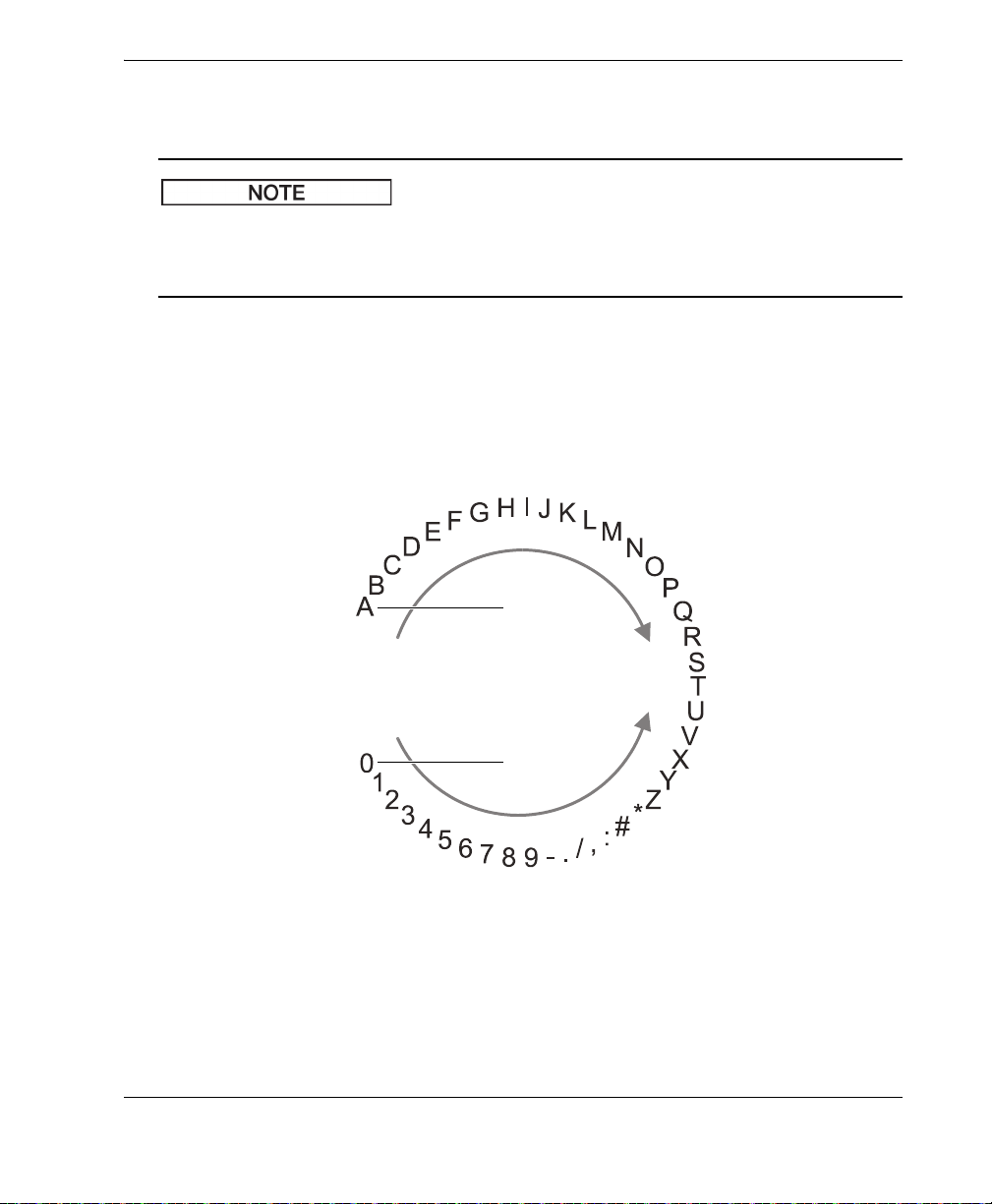
When the TEXT EDIT MODE is set to TRADITIONAL, select each character from a
hidden circular list of standard sorted letters, numbers, and special characters (see
Figure 3-10 on page 41). Only uppercase letters are available.
Figure 3-10 The character cycle of the traditional text edit method
To edit an alphanumeric parameter value using the traditional method
1. Select an alphanumeric parameter.
Software User Interface Elements 41
Page 52

DMTA-10022-01EN, Rev. C, January 2015
2. Use the [] and [] keys to select the character you want to enter. Hold down the
key to quickly cycle through the letters, numbers, and special characters.
3. Use the [] keys to move to the next character.
4. Repeat step 2 and step 3 to enter other characters.
5. If you need to move the position of the cursor in the value text box, use the [] or
[] key.
6. To insert a character at the cursor position, press [CAL ZERO].
The character at the cursor, and all those to the right, move one position to the
right, making space for one new character.
7. To delete the character at the cursor position, press [CAL VEL].
The character at the cursor is deleted, and any characters to the right move to the
left by one position.
8. Press [ENTER] to accept the character string and move to the next parameter.
42
Chapter 3
Page 53

DMTA-10022-01EN, Rev. C, January 2015
4. Initial Setup
The following sections describe basic system configurations.
4.1 Setting the User Interface Language and Other System Options
The 45MG can be configured to display the user interface in the following languages:
English, German, French, Spanish, Japanese, Chinese, Russian, Swedish, Italian,
Norwegian, Portuguese, or Czech. You can also set the character delimiting the radix
of a number.
The 45MG includes a beep tone generator that confirms when a key is pressed and
notifies you of an alarm condition. The beeper can be set to On or Off.
To save battery power while the instrument is not in use, enable the inactive time
function so that the instrument automatically turns off when no key has been pressed
and no measurement has been made within a period of about six minutes.
To change the user interface language and other system options
1. In the measurement screen, press [SETUP], and then select SYSTEM.
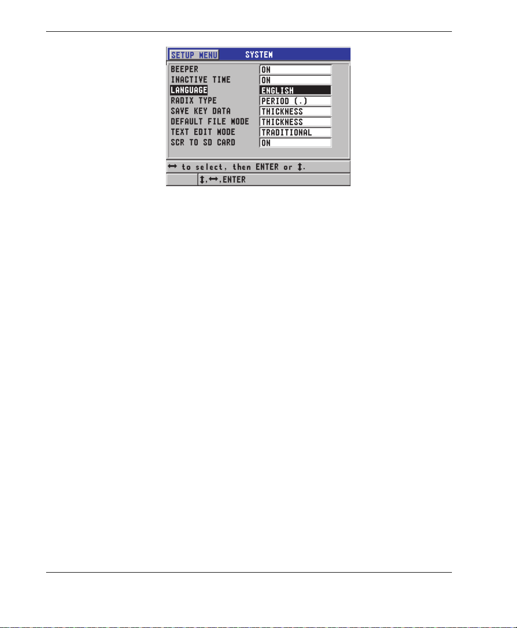
2. In the SYSTEM screen (see Figure 4-1 on page 44):
a) Set BEEPER to ON or OFF.
b) Set INACTIVE TIME to ON or OFF.
c) Set LANGUAGE to the desired language.
d) Set RADIX TYPE to the desired character (PERIOD or COMMA) in order to
separate the integer and the decimal digits.
Initial Setup 43
Page 54
DMTA-10022-01EN, Rev. C, January 2015
Figure 4-1 The SYSTEM screen
3. Press [MEAS] to return to the measurement screen.
4. Turn off the 45MG, and then turn it back on to activate the language change.
4.2 Selecting the Measurement Units
The 45MG can be set to show thickness measurements in inches or millimeters.
To set the measurement units
1. In the measurement screen, press [SETUP], and then select MEAS.
2. In the MEAS screen, set UNIT TYPE to INCH or MILLIMETER.
3. Press [MEAS] to return to the measurement screen.
4.3 Setting the Clock
The 45MG has a built-in date and time clock. You can set the date and the time and
select their format. The 45MG saves all measurement values with their acquisition
date.
To set the clock
1. In the measurement screen, press [SETUP], and then select SP MENU.
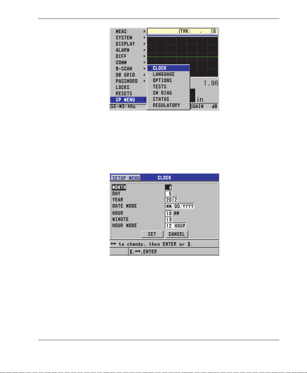
2. In the SP MENU (see Figure 4-2 on page 45), select CLOCK.
Chapter 4
44
Page 55
DMTA-10022-01EN, Rev. C, January 2015
Figure 4-2 The SP MENU screen
3. In the CLOCK screen (see Figure 4-3 on page 45), set the parameters to the
current date and time.
4. Set the desired DATE MODE and HOUR MODE, and then select SET.
Figure 4-3 The CLOCK screen
4.4 Changing Display Settings
The appearance of certain display elements, such as colors, brightness, waveform
rectification, and waveform trace, can be changed.
Initial Setup 45
Page 56
DMTA-10022-01EN, Rev. C, January 2015
NOTE
To change the display settings
1. In the measurement screen, press [SETUP], and then select DISPLAY.
Many of the display parameters are only visible when the Waveform or Datalogger
options have been activated.
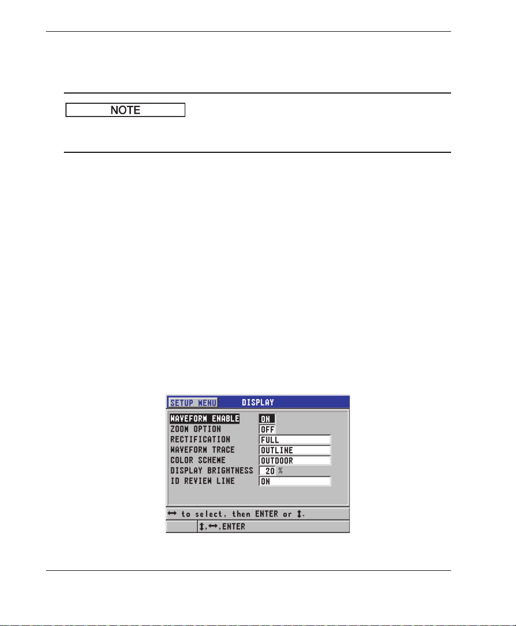
2. In the DISPLAY screen (see Figure 4-4 on page 46), select the desired parameter
and value for the following parameters:
• WAVEFORM ENABLE allows you to activate or deactivate the waveform
display (see “Waveform Software Option” on page 78 for details).
• ZOOM OPTION allows you to activate or deactivate the zoom function (see
“Activating the Zoom Function (Available Only with the Waveform Option)”
on page 84 for details).
• RECTIFICATION allows you to select one of the rectification modes (see
“Waveform Rectification” on page 80 for details).
• WAVEFORM TRACE is used to select one of the trace types (see “Waveform
Trace” on page 82 for details).
• COLOR SCHEME is used to select either the INDOOR or OUTDOOR
optimized visibility (see “Color Schemes” on page 47 for details).
• DISPLAY BRIGHTNESS is used to select one of the predefined brightness
levels (see “Display Brightness” on page 48 for details).
• ID REVIEW LINE is used to activate or deactivate the feature.
46
Figure 4-4 The DISPLAY screen
Chapter 4
Page 57
DMTA-10022-01EN, Rev. C, January 2015
Outdoor color schemeIndoor color scheme
3. Press [MEAS] to return to the measurement screen.
4.4.1 Color Schemes
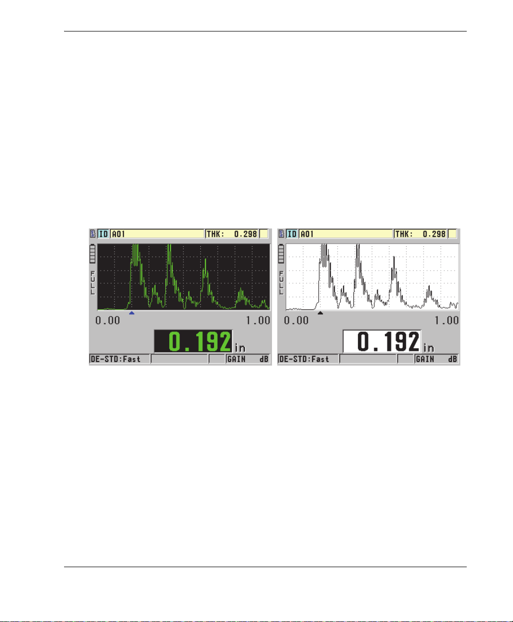
The 45MG offers two standard color schemes designed to provide the best display
visibility in indoor or outdoor lighting conditions (see Figure 4-5 on page 47).
To set the color scheme
1. In the measurement screen, press [SETUP], and then select DISPLAY.
2. In the DISPLAY screen (see Figure 4-4 on page 46), set the COLOR SCHEME to
INDOOR or OUTDOOR.
3. Press [MEAS] to return to the measurement screen.
Figure 4-5 Example of the indoor and the outdoor color schemes
The indoor scheme gives the best visibility when the instrument is used indoors or in
low-light conditions. The indoor scheme displays green characters and waveform
trace on a black background.
The outdoor scheme provides the best visibility when the instrument is used in direct
sunlight. The outdoor mode displays black characters and waveform trace on a white
background. For best readability in this document, most screen captures are shown in
the outdoor color scheme.
Initial Setup 47
Page 58
DMTA-10022-01EN, Rev. C, January 2015
NOTE
NOTE
Colored measurement values corresponding to specific alarm conditions only appear
when the indoor color scheme is selected.
4.4.2 Display Brightness
The 45MG display brightness can be adjusted by selecting the backlight intensity. The
display brightness can be set in 5 % increments from 0 % to 100 %. Choosing a high
percentage increases the brightness of the display. By default, the display brightness is
set to 20 %.
To set the display brightness
1. In the measurement screen, press [SETUP], and then select DISPLAY.
2. In the DISPLAY screen (see Figure 4-4 on page 46), set the DISPLAY
BRIGHTNESS to the desired percentage level.
3. Press [MEAS] to return to the measurement screen.
The 45MG uses a transflective color display that reflects ambient light and becomes
brighter in direct light. In brighter ambient conditions, the display brightness can be
set to a lower percentage.
Reducing the display brightness percentage increases the battery life. Battery life
specifications are based on the backlight brightness set to 20 %.
4.5 Adjusting the Measurement Update Rate
It is possible to select a predefined measurement update rate. When using dual
element transducers, the user can select between two measurement update rates:
Normal (4 Hz) or Fast (up to 20 Hz). Normal is the default setting for the
measurement update rate. When the Single Element option is activated and while
using a single element transducer, it is possible to select 4Hz, 8Hz, 16 Hz, or Max (up
Chapter 4
48
Page 59
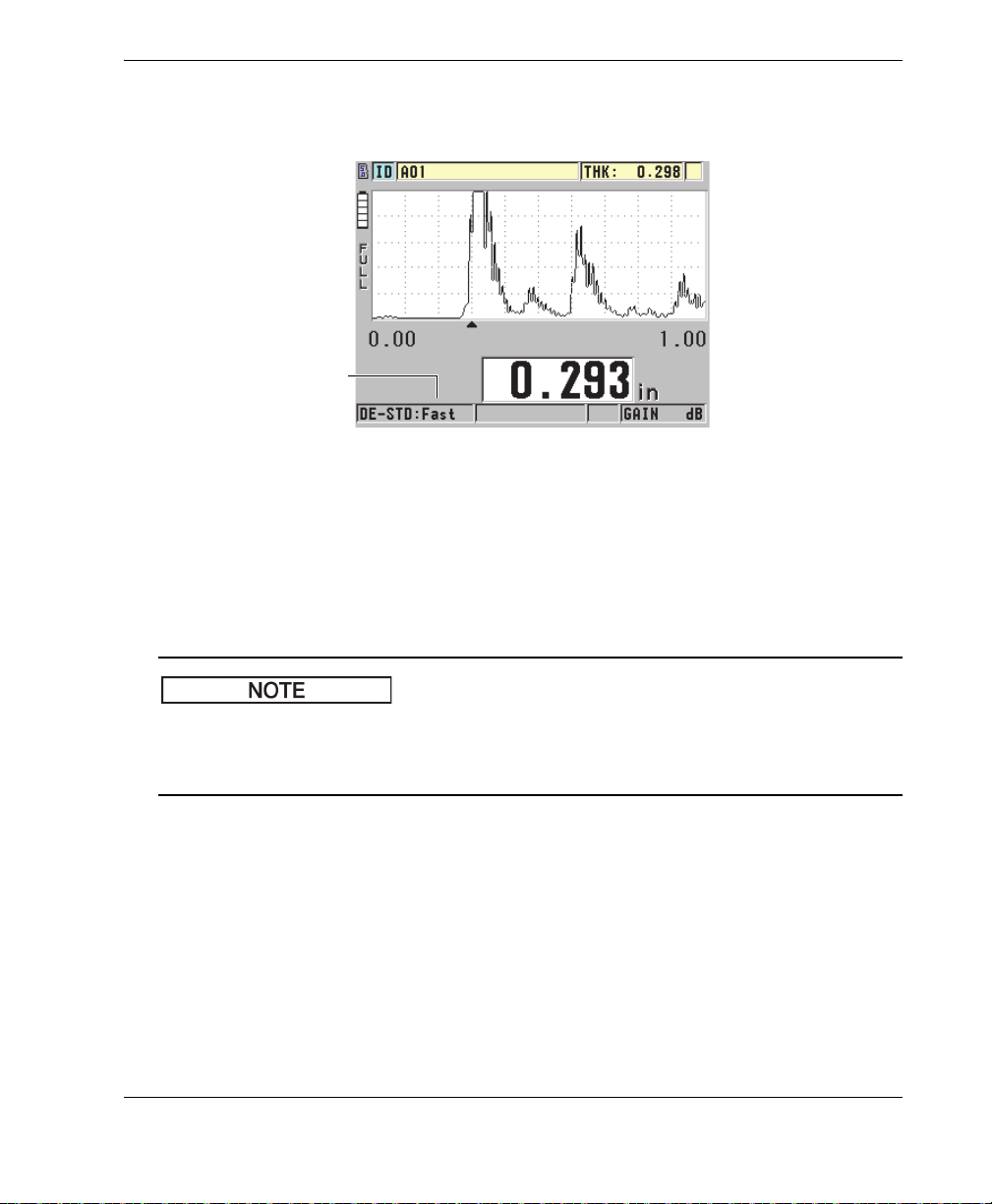
DMTA-10022-01EN, Rev. C, January 2015
Measurement update
rate indicator
NOTE
to 20 Hz). The measurement update rate indicator is permanently displayed on the
left side of the thickness measurement (see Figure 4-6 on page 49).
Figure 4-6 The measurement update rate indicator
The Fast update rate can be as high as 20 Hz, and is dependent on the measurement
type. This option is useful when making high-temperature thickness measurements in
order to help limit transducer contact time, or for applications where the transducer is
scanned over an area in order to determine the minimum thickness.
To adjust the measurement update rate
The 45MG automatically uses the fastest update rate when put into the Minimum or
Maximum mode (see “Using the Minimum, Maximum, or Min/Max Thickness
Mode” on page 129).
1. In the measurement screen, press [SETUP], and then select MEAS.
2. In the MEAS screen (see Figure 8-1 on page 142), set the MEASURE RATE to the
desired value.
3. Press [MEAS] to return to the measurement screen.
Initial Setup 49
Page 60

DMTA-10022-01EN, Rev. C, January 2015
4.6 Changing the Thickness Resolution
It is possible to change the thickness-measurement resolution, meaning the number of
digits shown to the right of the decimal point. The resolution selection affects all
displays and data output of values with thickness units. This includes measured
thickness, differential reference value, and alarm set points. The highest thickness
resolution with a dual element transducer is 0.01 mm (or 0.001 in.). The velocity is
always reported with full four-digit resolution.
The resolution can be reduced in certain applications where the extra precision of the
last digit is not required, or where extremely rough outside or inside surfaces make
the last thickness display digit unreliable.
The Single Element including High Resolution software option (P/N: 45MG-SE
[U8147022]) makes it possible to increase the resolution to 0.001 mm (or 0.0001 in.).
High resolution is available for measured thickness smaller than 102 mm (4 in.). High
resolution is not active with low-frequency transducers, or when the High Penetration
software option is activated.
To change the thickness-measurement resolution
1. In the measurement screen, press [SETUP], and then select MEAS.
2. In the MEAS screen (see Figure 8-1 on page 142), set RESOLUTION to the
desired option:
• STANDARD: 0.01 mm (or 0.001 in.) [default]
• LOW: 0.1 mm (or 0.01 in.)
• Optional HIGH: 0.001 mm (or 0.0001 in.)
3. Press [MEAS] to return to the measurement screen.
50
Chapter 4
Page 61

DMTA-10022-01EN, Rev. C, January 2015
5. Basic Operation
The following sections describe the basic operation for the 45MG ultrasonic thickness
gage.
5.1 Setting Up the Transducer
The 45MG operates with a full line of single element (optional software) and dual
element transducers. The 45MG automatically recognizes standard D79X dual
element transducers, and automatically loads the appropriate predefined setup. The
predefined setup contains ultrasonic velocity for the stainless steel step block
supplied with the instrument. With dual element transducers, you need to perform a
transducer zero compensation.
For Single Element or High Penetration software options and single element
transducers, you need to manually recall an appropriate setup. The 45MG is factory
shipped with default conditions for the purchased transducers set up using an
approximate sound velocity for the stainless steel test block provided with the
instrument. The default conditions are selected to facilitate instrument usage for your
applications.
To set up the transducer
1. Plug the transducer into the transducer connector(s) on the top of the 45MG case
(see Figure 5-1 on page 52), using only T/R 1 for a single element transducer.
Basic Operation 51
Page 62
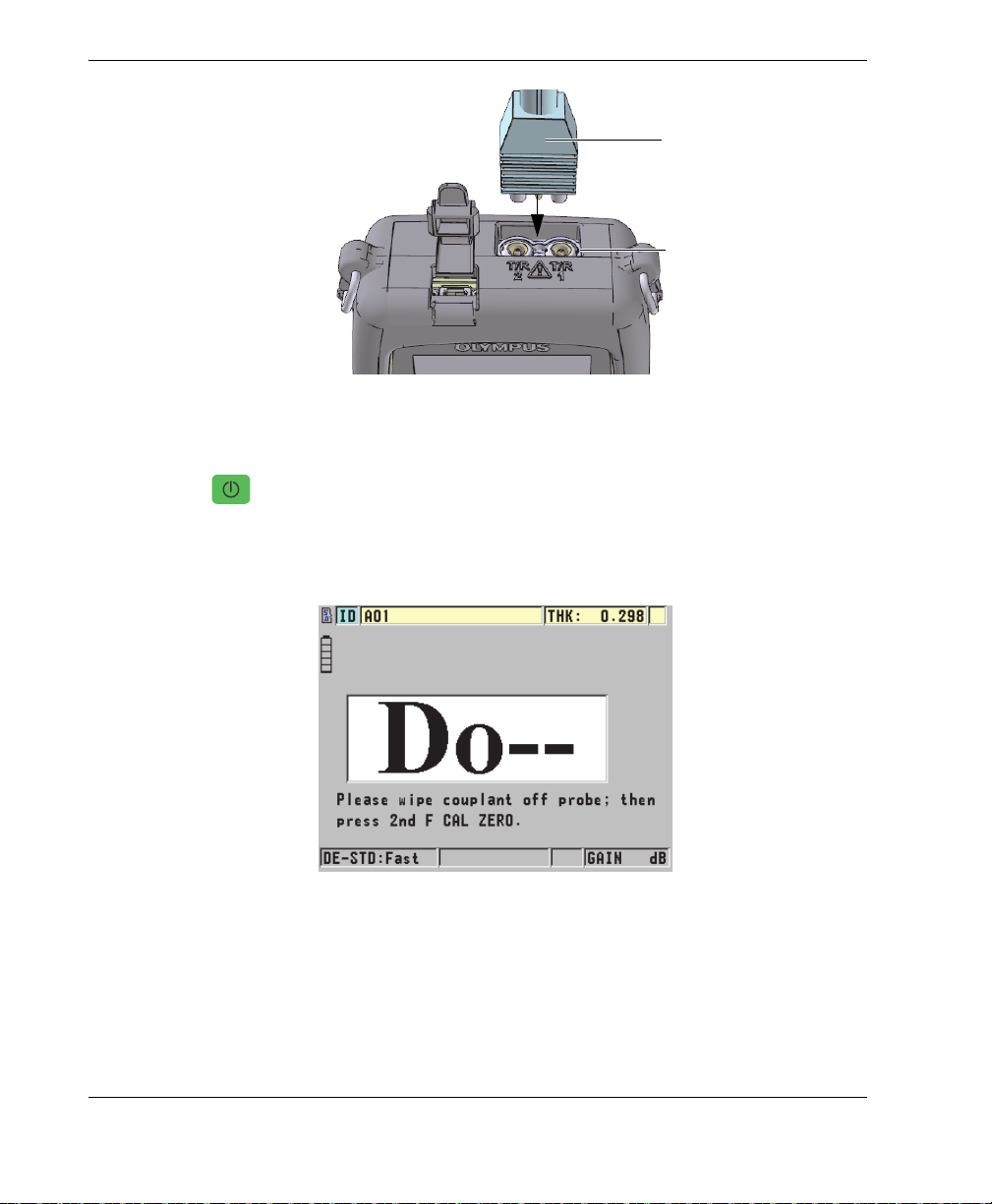
DMTA-10022-01EN, Rev. C, January 2015
T/R 1 connector for a
single element transducer
Standard dual element
transducer connector
Figure 5-1 Plugging in the transducer
2. Press to start the instrument.
The measurement screen appears. With a standard D79X dual element
transducer, the “Do--” message appears in the measurement screen (see
Figure 5-2 on page 52).
Figure 5-2 Initial screen with a standard D79X dual element transducer
3. For dual element transducers, perform the transducer zero compensation:
a) Wipe the couplant off the tip of the transducer.
b) Press [2nd F], [CAL ZERO] (Do ZERO).
Chapter 5
52
Page 63
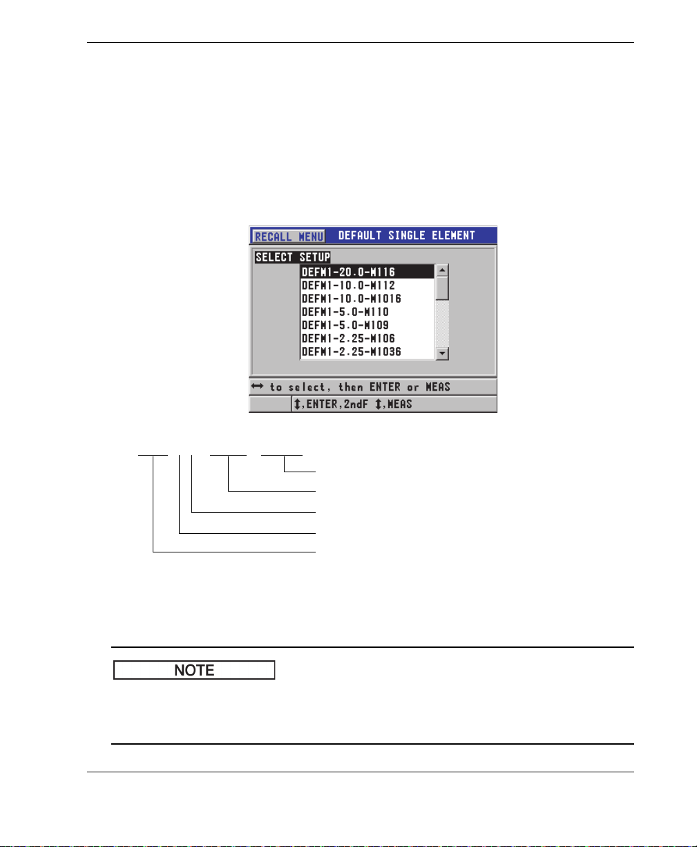
DMTA-10022-01EN, Rev. C, January 2015
D E F M 1 - 2 0 . 0 / M 1 1 6
Probe part number (ex. M116)
Probe frequency (ex. 20.0 MHz)
Mode: 1, 2, 3
Material: M
-Metal, P-Plastic
DEF: Default
Default setup naming convention:
NOTE
4. For the Single Element software option and a single element transducer, load an
appropriate setup:
a) Press [2nd F], [FREEZE] (XDCR RECALL).
b) In the menu, select the default choice for the probe type that you use (ex.:
DEFAULT SINGLE ELEMENT).
c) In the DEFAULT screen for the type of probe you are using (see the example
shown in Figure 5-3 on page 53), highlight the setup in the list of available
default setups for the transducer that you are using.
The setups listed as USER-1 through USER-35 can be renamed for special
applications. Refer to “Custom Setups for Single Element Transducers” on page 165
for more details on setups.
Figure 5-3 Selecting a default single element transducer setup
Basic Operation 53
Page 64

DMTA-10022-01EN, Rev. C, January 2015
d) Press [MEAS] to automatically recall the setup parameters for the chosen
setup and return to the measurement screen.
5.2 Calibration
Calibration is the process of adjusting the instrument to perform accurate
measurements on a particular material at a given temperature using a known
transducer. Calibration of the instrument is always necessary prior to inspection of a
specific material. The measurement accuracy is only as accurate as the calibration
performed.
The following three types of calibration must be performed:
Transducer zero compensation ([Do ZERO])
For dual element transducers only, calibrate for the sound transit time in each of
the dual transducer delay lines. This compensation varies in each transducer unit,
and with the temperature. The transducer zero-compensation procedure must be
performed whenever the unit is powered on, the transducer is changed, or the
transducer temperature changes significantly (see “Setting Up the Transducer” on
page 51 and “Transducer Zero Compensation” on page 58).
Material sound velocity calibration ([CAL VEL])
Perform a velocity calibration using a thick test block of the measured material,
and of known thickness, or by manually entering a previously determined
material sound velocity. You must perform this procedure for each new measured
material (see “Calibrating the Instrument” on page 55 and “Material Sound
Velocity and the Zero Calibrations” on page 59).
Zero Calibration ([CAL ZERO])
Perform a zero calibration using a thin test block of the measured material, and of
known thickness. Unlike the transducer zero compensation and the material
sound velocity calibration, this procedure is not required unless you need the best
absolute accuracy (better than ±0.10 mm or ±0.004 in.). The procedure only needs
to be performed once for each new transducer and material combination. It is not
necessary to repeat the zero calibration when the transducer temperature
changes; transducer zero compensation is responsible for that task (see
“Calibrating the Instrument” on page 55 and “Material Sound Velocity and the
Zero Calibrations” on page 59).
Chapter 5
54
Page 65
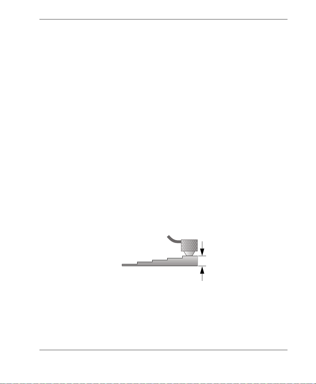
DMTA-10022-01EN, Rev. C, January 2015
12.7 mm (0.500 in.)
5.2.1 Calibrating the Instrument
To make accurate measurements, you need to perform the following calibrations:
• Material sound velocity calibration
•Zero calibration
The calibrations must be performed using a thick and a thin sample of precisely
known thicknesses. The sample must be made of the same material as the parts to be
inspected (see “Test Blocks” on page 58 for details on test blocks).
The following procedure is illustrated using a dual element probe and a five-step test
block. Refer to “Calibration” on page 54 for more details on the calibration process.
To calibrate the instrument
1. To perform the material sound velocity calibration using an instrument with or
without the Waveform software option (see Figure 5-5 on page 56):
a) Place a drop of couplant on the surface of the thick part of the test block.
b) Couple the transducer to the thick part of the test block using moderate to
firm pressure (see Figure 5-4 on page 55).
The waveform (optional) and the thickness reading appear on the screen.
c) Press [CAL VEL].
d) Once the thickness reading is stable, press [ENTER].
e) Using the arrow keys, edit the thickness value to match the known thickness
of the thick part of the test block.
Figure 5-4 Sound velocity calibration on a five-step test block — Thick part
Basic Operation 55
Page 66
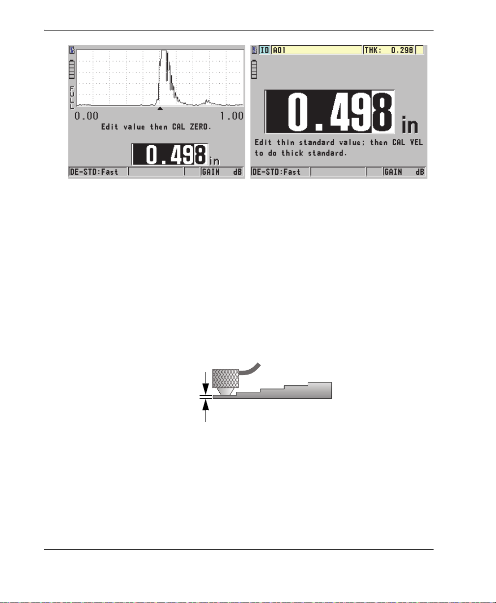
DMTA-10022-01EN, Rev. C, January 2015
Without Waveform optionWith Waveform option
2.54 mm
(0.100 in.)
Figure 5-5 Performing the sound velocity calibration on a five-step test block
2. To perform the zero calibration using an instrument with or without the
Waveform option (see Figure 5-7 on page 57):
a) Place a drop of couplant on the surface of the thin part of the test block.
b) Couple the transducer to the thin part of the test block (see Figure 5-6 on
page 56), and then press [CAL ZERO].
c) Once the thickness reading is stable, press [ENTER].
d) Using the arrow keys, edit the thickness value to match the known thickness
of the thin part of the test block.
56
Figure 5-6 Sound velocity calibration on a five-step test block — Thin part
Chapter 5
Page 67
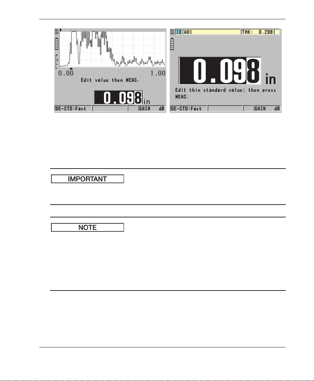
DMTA-10022-01EN, Rev. C, January 2015
Without Waveform optionWith Waveform option
IMPORTANT
NOTE
Figure 5-7 Performing the zero calibration on a five-step test block
3. Press [MEAS] to complete the calibration and return to the measurement screen.
If you turn off the instrument before pressing [MEAS], the velocity will not be
updated to the new value. Instead, the instrument retains the previous value.
When the 45MG detects an error in the calibration procedure, it successively displays
the following messages in the help text bar before returning to the measurement
screen:
“Potential wrong echo detected!”
“Invalid calibration results!”
In such case, the velocity is not changed. The probable cause is that an incorrect
thickness value was entered, or the incorrect back-wall echo was detected.
Basic Operation 57
Page 68
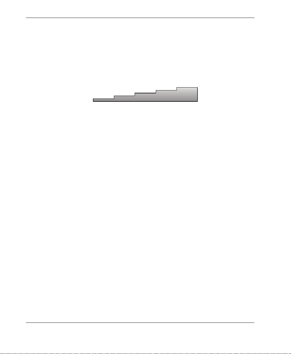
DMTA-10022-01EN, Rev. C, January 2015
5.2.2 Test Blocks
The 45MG comes with a cylindrical stainless steel test block with two thicknesses.
Two precisely known test-block thicknesses can be used to perform the material
sound velocity and the zero calibrations.
Precision step test blocks are also often used when more than two known thicknesses
are needed (see Figure 5-8 on page 58).
Figure 5-8 Example of a five-step test block
When performing the material sound velocity and zero calibrations, you must use a
test block with the following characteristics:
• Made from the same material as the part to be tested.
• Has two or more precisely known thicknesses.
• Has one part as thin as the thinnest section of the parts to be tested in order to
perform the zero calibration. The surface condition should be similar to that of the
tested parts. Rough surfaces generally reduce the accuracy of measurements, but
simulating actual surface conditions on the calibration block can help to improve
results.
• Has one part as thick as the thickest section of the parts to be tested, in order to
perform the material sound velocity calibration. The front and back surfaces
should be smooth and parallel.
• Be at the same temperature as the samples to be measured.
5.2.3 Transducer Zero Compensation
Perform a transducer zero compensation by pressing [2nd F], [CAL ZERO]
(Do ZERO) whenever the zero indicator (Do--) appears. This procedure should also
be performed when the dual element transducer temperature has changed.
Chapter 5
58
Page 69
DMTA-10022-01EN, Rev. C, January 2015
NOTE
NOTE
The frequency at which you perform a transducer zero-compensation procedure
depends on the rate of change of the internal temperature of the dual element
transducer. This is related to the material surface temperature, the frequency of
transducer application, the length of time the transducer is held in contact with the
material, and the accuracy that you want to obtain.
When measurements are made on surfaces that are significantly above room
temperature, the zero point should be recalibrated on a regular basis. This is less
important for transducers with part numbers D790-SM, D791-RM, D797-SM, and
D798 than for other transducers with various types of resin delay lines.
For high-temperature measurements, Olympus recommends developing a transducer
zero-compensation schedule that takes these factors into account. For example, use
the D790-SM, D791-RM, or D797-SM for high-temperature applications, thereby
minimizing the frequency of the zero compensation. The D790-SM and D791-RM can
also be used for general-purpose applications.
5.2.4 Material Sound Velocity and the Zero Calibrations
The 45MG performs a calibration doubling verification to help prevent miscalibration on thin samples. Doubling occurs when the instrument measures the time
of flight to the second back-wall echo rather than measuring the time of flight to the
first back-wall echo. The 45MG compares the measured time of flight to the expected
time of flight based on the current sound velocity. The 45MG displays a warning
message if doubling is suspected. Doubling can occur when measuring a thickness
that is below the minimum range of the transducer, or when using a transducer that is
worn out, or getting low in sensitivity.
You can also achieve a material sound velocity and zero calibration procedure by
performing the operations in the reverse order, starting with the zero calibration,
followed by the material sound velocity calibration.
Basic Operation 59
Page 70
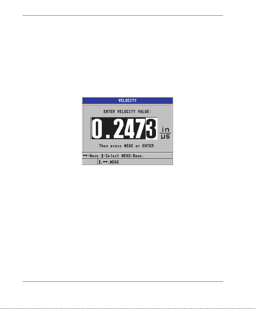
DMTA-10022-01EN, Rev. C, January 2015
5.2.5 Entering a Known Material Sound Velocity
When preparing to measure thicknesses on parts made of a different material, if you
know the sound velocity for the material, you can enter it directly without performing
a material sound velocity calibration procedure.
To enter a known material sound velocity
1. In the measurement screen, press [2nd F], [CAL VEL] (VEL).
2. In the VELOCITY screen (see Figure 5-9 on page 60), use the arrow keys to edit
the velocity to the known value.
Figure 5-9 Entering a known material sound velocity
3. Press [MEAS] to return to the measurement screen.
5.2.6 Locked Calibrations
The 45MG includes a password-protected locking function to prevent changes to
setups, and prevent access to certain functions. A change to the calibration is one
action that can be locked. In such case, the message shown in Figure 5-10 on page 61
appears momentarily on the help text bar (see “Locking the Instrument” on page 136
for details).
Chapter 5
60
Page 71
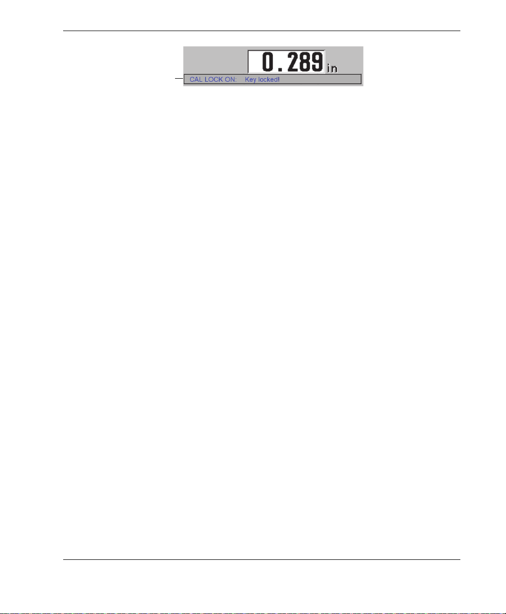
DMTA-10022-01EN, Rev. C, January 2015
Message
Figure 5-10 The calibration lock message
5.2.7 Factors Affecting Performance and Accuracy
The following factors affect the performance of the instrument and the accuracy of the
thickness measurements.
Calibration
The accuracy of any ultrasonic measurement is only as good as the accuracy and
care with which you calibrate the instrument. The 45MG ships from the factory
with standard setups for a number of transducers and applications. In certain
cases, it may be desirable to optimize these setups for specific measurement
situations. In all cases, it is essential to perform the velocity and zero calibrations
whenever the test material or transducer is changed. Periodic checks with
samples of known thicknesses are recommended to verify that the gage is
operating properly.
Surface roughness of the test piece
The best measurement accuracy is obtained when both the front and back
surfaces of the test piece are smooth. When the contact surface is rough, the
minimum thickness that can be measured will be increased as a result of sound
reverberating in the increased thickness of the couplant layer. Additionally, when
the two test-piece surfaces are rough, the slightly different multiple sound paths
seen by the transducer may cause distortion in the returning echo, resulting in
measurement inaccuracies.
Coupling technique
In mode 1 (contact transducer) measurements, the couplant layer thickness is part
of the measurement, and is compensated by a portion of the zero offset. If
maximum accuracy is to be achieved, the coupling technique must be consistent.
In order to accomplish consistent measurements, use a couplant of reasonably
low viscosity, employ only enough couplant to achieve a reasonable reading, and
apply the transducer with uniform pressure. Practice will determine the degree of
moderate to firm pressure needed to produce repeatable readings. In general,
smaller-diameter transducers require less coupling force to squeeze out excess
Basic Operation 61
Page 72

DMTA-10022-01EN, Rev. C, January 2015
couplant than larger-diameter transducers. In all modes, tilting the transducer
distorts echoes, and causes inaccurate readings, as noted below.
Curvature of the test piece
A related issue involves the alignment of the transducer with respect to the test
piece. When measuring on curved surfaces, it is important that the transducer be
placed approximately on the centerline of the part, and held steadily as close to
the surface as possible. In some cases, a spring-loaded V-block holder may be
helpful in maintaining this alignment. In general, as the radius of curvature
decreases, the size of the transducer should be reduced, and transducer alignment
becomes more critical. For very small radii, an immersion approach is necessary.
In some cases, it may be useful to observe the waveform display as an aid to
maintaining optimum alignment. Observe the best method for holding a
transducer with the aid of a waveform display. On curved surfaces, it is important
to use only enough couplant to obtain a reading. Excess couplant forms a fillet
between the transducer and the test surface where sound reverberates, and
possibly creates spurious signals that may trigger false readings.
Taper or eccentricity
If the contact surface or back surface of the test piece is tapered or eccentric with
respect to the other, the return echo is distorted due to the variation of the sound
path across the width of the beam. The accuracy of the measurement is therefore
reduced. In severe cases, no measurement is possible.
Acoustic properties of the test material
There are several conditions in certain engineering materials that can potentially
limit the accuracy and range of ultrasonic thickness measurements:
• Sound scattering:
In materials such as cast stainless steel, cast iron, fiberglass, and composites,
sound energy scatters from individual crystallites in the casting, or from
boundaries of dissimilar materials within the fiberglass or composite.
Porosity in any material can have the same effect. Adjust the instrument
sensitivity to prevent detection of these spurious scatter echoes. This
compensation can in turn limit the ability to discriminate a valid return echo
from the back wall of the material, thereby restricting the measurement range.
• Sound attenuation or absorption:
In many organic materials, such as low-density plastics and rubbers, sound
energy is attenuated very rapidly at the frequencies used for ultrasonic
gaging. This attenuation typically increases with temperature. The maximum
thickness that can be measured in these materials is often limited by
attenuation.
Chapter 5
62
Page 73

DMTA-10022-01EN, Rev. C, January 2015
• Velocity variations:
An ultrasonic thickness measurement is accurate only to the degree that
material sound velocity is consistent with the instrument calibration. Some
materials exhibit significant variations in sound velocity from point to point.
This happens in certain cast metals due to the changes in grain structure that
result from varied cooling rates, and the anisotropy of sound velocity with
respect to grain structure. Fiberglass can show localized velocity variations
due to changes in the resin/fiber ratio. Many plastics and rubbers show a
rapid change in sound velocity with temperature, and as such, velocity
calibration must be performed at the temperature of the location where the
measurements are made.
Phase reversal or phase distortion
The phase or polarity of a returning echo is determined by the relative acoustic
impedances (density × velocity) of the boundary materials. The 45MG performs
computation based on the customary situation, where the test piece is backed by
air or a liquid, both of which have a lower acoustic impedance than metals,
ceramics, or plastics. However, in some specialized cases, such as measurement of
glass or plastic liners over metal, or copper cladding over steel, this impedance
relationship is reversed, and the echo appears phase-reversed. In such cases, it is
necessary to change the appropriate echo detection polarity in order to maintain
accuracy (see “Detection of Echo 1 and Echo 2” on page 179). A more complex
situation can occur in anisotropic or inhomogeneous materials, such as
coarse-grain metal castings or certain composites, where material conditions
result in the existence of multiple sound paths within the beam area. In such
cases, phase distortion can create an echo that is neither cleanly positive nor
negative. Careful experimentation with reference standards is necessary in such
cases in order to determine the effects on measurement accuracy.
5.3 Measuring Thicknesses
You can start performing thickness measuring as soon as a transducer is connected
(see “Setting Up the Transducer” on page 51) and the instrument is calibrated (see
“Calibrating the Instrument” on page 55).
To measure thicknesses
1. Apply couplant to the measurement spot on the test block or tested part.
Basic Operation 63
Page 74
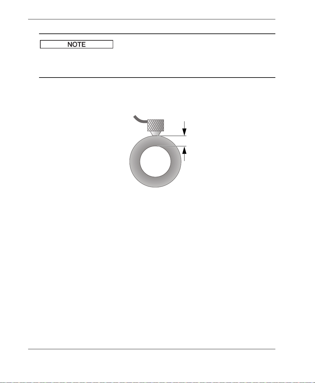
DMTA-10022-01EN, Rev. C, January 2015
NOTE
12.7 mm (0.500 in.)
In general, use a thinner couplant (such as propylene glycol, glycerin, or water) for
smooth material surfaces. Rough surfaces require a more viscous couplant, such as
gel or grease. Special couplants are required for high-temperature applications.
2. Using moderate to firm pressure, couple the tip of the transducer to the surface of
the test material, and keep the transducer as flat as possible on the material
surface (see Figure 5-11 on page 64).
Figure 5-11 Coupling a dual element transducer
3. Read the measured thickness value for the tested part (see Figure 5-12 on
page 65).
Chapter 5
64
Page 75
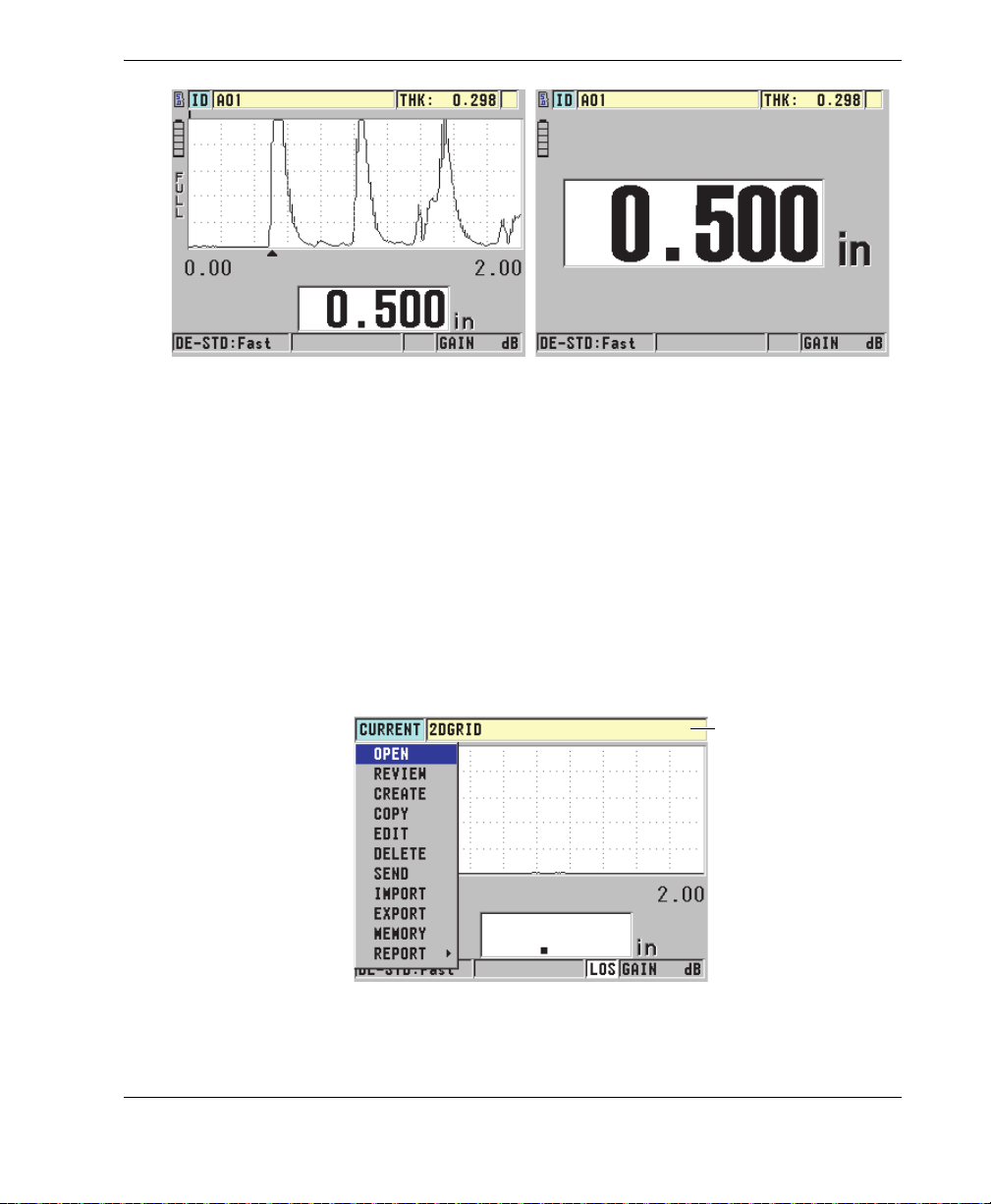
DMTA-10022-01EN, Rev. C, January 2015
Without Waveform software optionWith Waveform software option
Name of active file
Figure 5-12 Reading the measured thickness
5.4 Saving Data
The 45MG optional datalogger is a file-based system, in which one file is opened at a
time. The active file stores a measurement at a thickness-measurement location ID.
Each time you press [SAVE], the displayed value is saved to the active file at the
current ID. The ID is automatically incremented for the next measurement. When you
press [FILE], the name of the active file appears in the ID bar above the menu (see
Figure 5-13 on page 65).
Figure 5-13 The active file name appearing in the ID bar
Basic Operation 65
Page 76

DMTA-10022-01EN, Rev. C, January 2015
The NONAME00 increment-type file, starting with the 001 ID, is the active file by
default when you first use the 45MG, or after resetting the instrument memory.
Various types of files can be created, and IDs can be defined to represent various 1-D,
2-D, or 3-D thickness-measurement locations. When the instrument is restarted, it
automatically opens the last file used.
The following special cases may occur:
• When the thickness value is blank, “———” is saved rather than a value.
• When a measurement is already stored at the current ID, the new value
overwrites the old thickness reading unless the overwrite protection is enabled
(see “Setting the ID Overwrite Protection” on page 115).
• When the ID increment reaches the end of a sequence and cannot be updated,
Last ID appears on the help text bar, a long beep sound is emitted (when the
beeper is active), and the ID on the display remains unchanged.
Refer to “Datalogger Option” on page 88 for more information on the datalogger.
To save data at the current ID in the active file
While the desired thickness value and waveform are displayed, press [SAVE] to
save the measured thickness value.
OR
To save the measured thickness value and the waveform, set the SAVE KEY
DATA to THICKNESS + WF in the SYSTEM menu (see Figure 4-1 on page 44).
66
Chapter 5
Page 77
DMTA-10022-01EN, Rev. C, January 2015
6. Software Options
The available software options can be used to increase the capability of the already
versatile 45MG (see Table 3 on page 67).
Table 3 45MG software options
Option
Echo-to-Echo &
THRU-COAT
Datalogger
Capability
Waveform 45MG-WF
Part
number
45MG-EETC
(U8147021)
45MG-DL
(U8147020)
(U8147019)
Description
Enables the 45MG to make measurements in
Echo-to-Echo and THRU-COAT modes. These
features are used to measure the remaining
metal thickness when the material is
painted/coated.
Note: Manual Echo-to-Echo is only available
when the Waveform option is also purchased.
Adds a bidirectional alphanumeric file-based
datalogger. This option also includes a USB
communication cable and the GageView
interface program.
Provides the added capability of viewing the
live A-scan of the ultrasonic signal.
Software Options 67
Page 78

DMTA-10022-01EN, Rev. C, January 2015
Table 3 45MG software options (continued)
Option
Single Element
including High
Resolution
(see
“Measurements
with Optional
THRU-COAT,
D7906, and
D7908
Transducers” on
page 76)
High
Penetration with
Single Element
(see “HighPenetration
Software
Option” on
page 88)
When you order a software option with your original 45MG purchase, the option
comes preactivated. Software options can also be purchased at a later date. The
software options can be activated by entering an activation code in the instrument,
without the need to return the instrument to the factory. (see “Activating Software
Options” on page 68).
Part
number
45MG-SE
(U8147022)
45MG-HP
(U8147023)
Description
Enables the 45MG to use single element
transducers. With this option, the user can
recall default single element transducers, and
also create and store custom single element
transducer setups. This feature also increases
the thickness resolution to either 0.001 mm or
0.0001 in. for single element transducers with a
frequency ≥2.25 MHz.
Enables the 45MG to use low-frequency single
element transducers (as low as 0.5 MHz) for
thickness measurements in attenuating and
sound scattering materials.
Contact your local Olympus representative for more information about ordering
software options. Refer to Table 3 on page 67 for the software-option part numbers.
6.1 Activating Software Options
Each 45MG has a unique serial number code. A provided option key specific to a
particular 45MG activates the purchased software options only on that specific 45MG
unit. A single-option key is capable of activating one, several, or all software options.
Chapter 6
68
Page 79
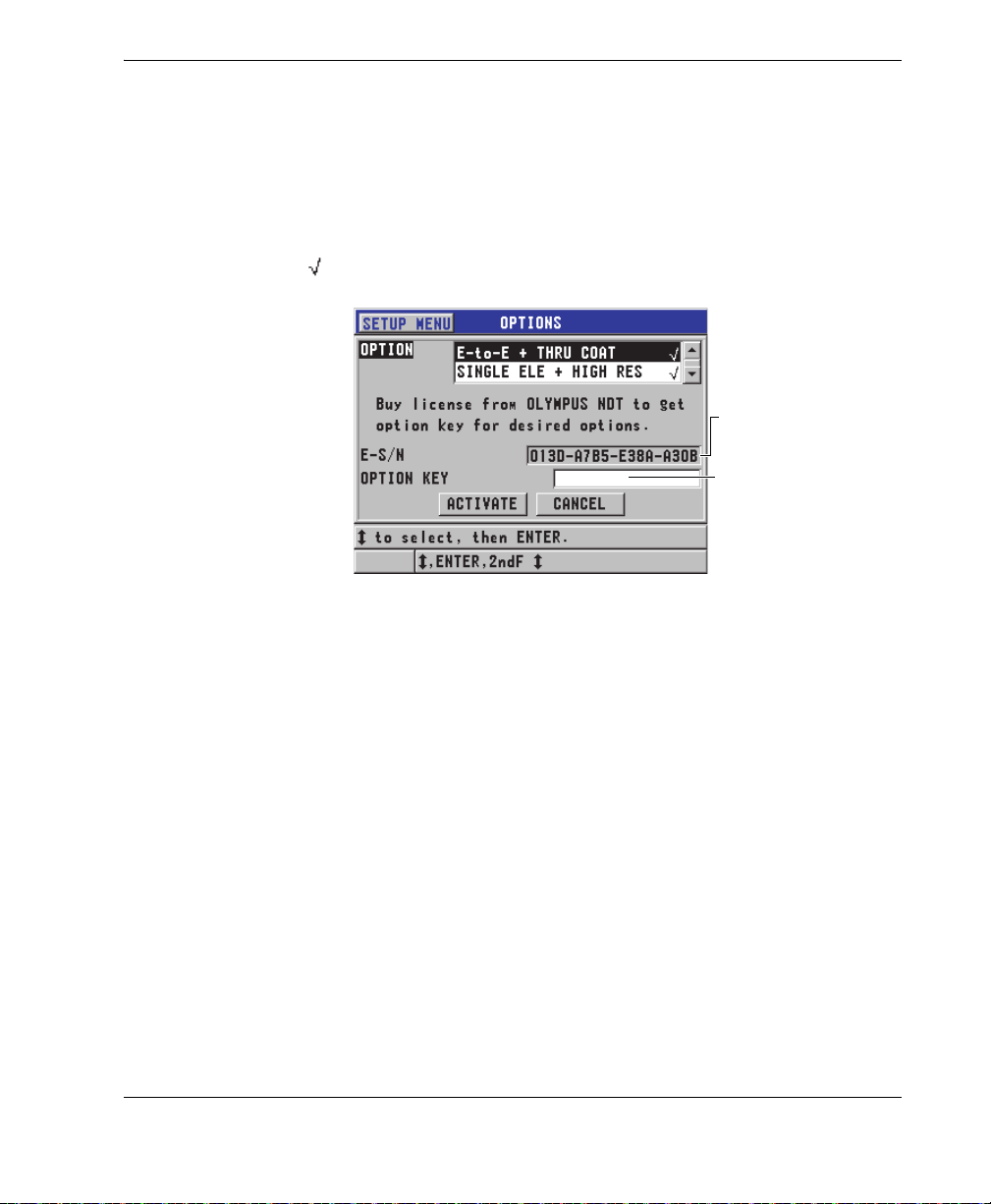
DMTA-10022-01EN, Rev. C, January 2015
Alphanumeric serial
number
Option key text box
To activate a software option
1. In the measurement screen, press [SETUP], and then select SP MENU.
2. In the SP MENU (see Figure 4-2 on page 45), select OPTIONS (see Figure 6-1 on
page 69), take note of the 16-digit alphanumeric serial number appearing in the
E-S/N field.
The OPTION list indicates the actual status of the software options, where the
check mark ( ) indicates that the option is activated.
Figure 6-1 The OPTIONS screen
3. To purchase one or more software options, contact your local Olympus
representative and provide the alphanumeric serial number (E-S/N).
Your Olympus representative will provide you with the corresponding option
key.
4. In the OPTIONS screen (see Figure 6-1 on page 69):
a) Enter the option key in the OPTION KEY text box provided to you from the
Olympus representative.
b) Select ACTIVATE.
5. Restart the instrument to complete the activation.
Software Options 69
Page 80
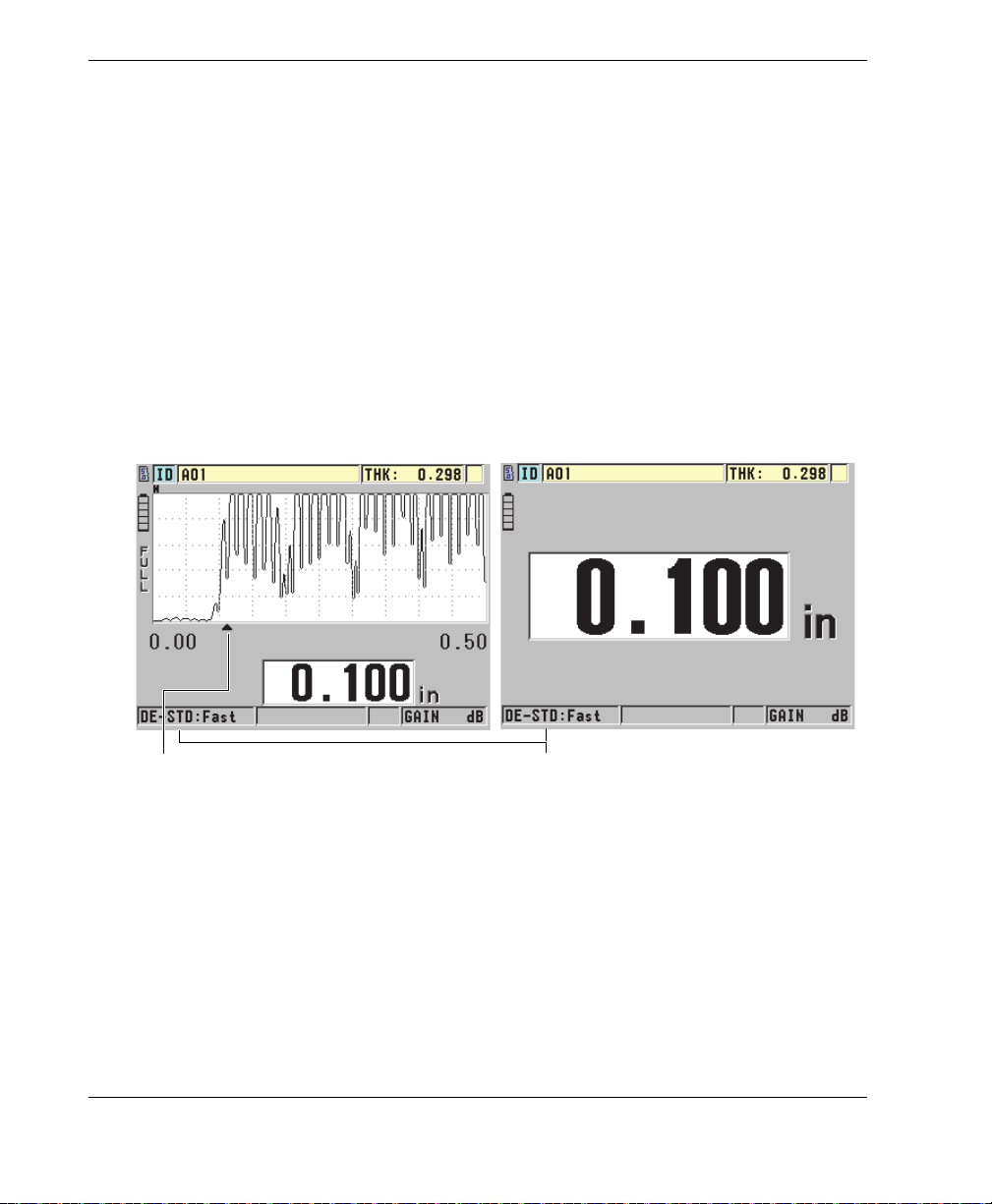
DMTA-10022-01EN, Rev. C, January 2015
Dual element (DE) standard (STD) echo detection mode
Echo detection marker
6.2 Echo Detection Modes with Dual Element Transducers
With dual element transducers, the 45MG offers three echo detection modes that
allow you to measure thicknesses in various material conditions. A description of
each of the three echo detection modes (STANDARD, optional AUTO E-TO-E, and
MANUAL E-TO-E) follows:
STANDARD
The standard echo detection mode measures the thickness based on the time of
flight between the main bang and the first back-wall echo. Use this mode for
uncoated materials.
The DE-STD indicator appears to the left of the thickness reading, and a
triangular echo detection marker appears at the back-wall echo, below the
waveform display (see Figure 6-2 on page 70).
AUTO E-TO-E (Optional)
70
Figure 6-2 Measuring with the standard echo detection mode
The automatic Echo-to-Echo detection mode measures the thickness using the
time of flight between two consecutive back-wall echoes. Use this mode for
painted or coated materials, because the time interval between consecutive backwall echoes excludes the time of flight through a paint, resin, or coating layer.
The DE-AEtoE indicator appears to the left of the thickness reading.
When the Waveform software option is enabled, the triangular marker is replaced
Chapter 6
Page 81
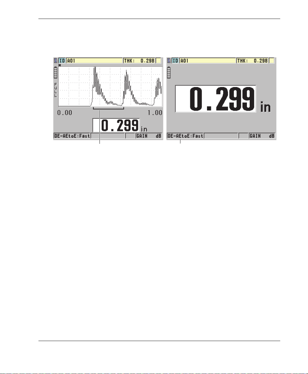
DMTA-10022-01EN, Rev. C, January 2015
Echo-to-echo
detection bar
Dual element (DE) automatic Echo-to-Echo (AEtoE)
detection mode
by an Echo-to-Echo detection bar that indicates the exact pair of back-wall echoes
used to determine the thickness (see Figure 6-3 on page 71). The echo height is
automatically adjusted to a preset level.
Figure 6-3 Measuring with the automatic Echo-to-Echo detection mode
MANUAL E-TO-E (optional and only available when Echo-to-Echo and the
Waveform options are activated)
The manual Echo-to-Echo detection mode also measures the thickness using the
time of flight between two consecutive back-wall echoes. However, the gain and
blanking parameters can also be manually adjusted in this mode. This mode is
useful when material conditions produce noisy signals that could render the
automatic mode less effective.
The DE-MEtoE indicator appears to the left of the thickness reading. The Echo-toEcho detection bar is similar to the automatic Echo-to-Echo mode, but includes
the adjustable E1 blank bar that indicates the area to exclude for echo detection
(see Figure 6-4 on page 72). Following the E1 blank, the instrument detects the
next echo with an amplitude of at least 20 % of the waveform display height. In
this mode, press [GAIN/WAVE ADJ], and then use the arrow keys to adjust the
EXT BLANK, the E1 BLANK, and the GAIN parameters.
Software Options 71
Page 82
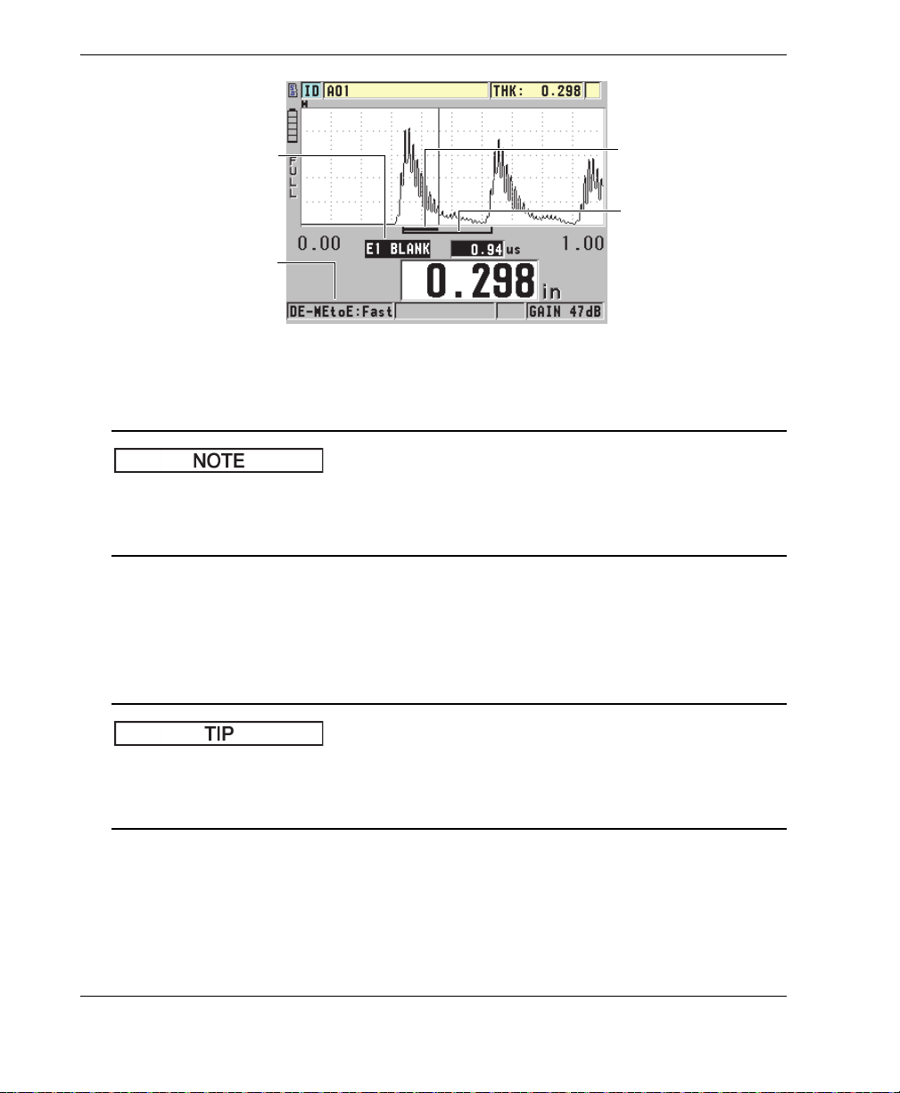
DMTA-10022-01EN, Rev. C, January 2015
Dual element (DE)
manual Echo-to-Echo
(MEtoE) detection mode
E1 blank bar
Echo-to-Echo detection
bar
[WAVE ADJ] parameter
NOTE
TIP
Figure 6-4 Measuring with the manual Echo-to-Echo detection mode
In severe corrosion situations where valid multiple echoes are not present, you must
use either the standard or optional THRU-COAT mode in order to be able to measure
thicknesses.
Dual element transducers can be used in all three modes, and all measurement,
display, and datalogger functions can be used with the echo-to-echo modes. The
internal datalogger recognizes all necessary echo-to-echo information, and saves it in
order to upload and download thickness, waveform, and setup data.
It is not necessary to switch between echo detection modes when measuring both
coated and uncoated areas, because it is possible to measure uncoated wall
thicknesses using an echo-to-echo mode.
To change the echo detection mode
1. In the measurement screen, press [SETUP], and then select MEAS.
Chapter 6
72
Page 83

DMTA-10022-01EN, Rev. C, January 2015
NOTE
2. In the MEAS screen, set the MEAS MODE to the desired echo detection mode:
STANDARD, AUTO E-TO-E (optional), or MANUAL E-TO-E (only available
with the Waveform option).
When switching between standard and Echo-to-Echo modes, it may be necessary to
perform a second [CAL ZERO], because the zero offset is different for each
measurement mode. The 45MG can store two different zero calibrations, one for
standard mode, and the other for Echo-to-Echo mode.
3. To perform the zero calibration again:
a) Place a drop of couplant on the surface of the thin part of the test block.
b) Couple the transducer to the thin part of the test block, and then press
[CAL ZERO].
c) Once the thickness reading is stable, press [ENTER].
d) Using the arrow keys, edit the thickness value to match the known thickness
of the thin part of the test block.
6.2.1 Blanking Adjustments in Manual Echo-to-Echo Detection Mode
The 45MG offers two blanking functions to help detect valid echoes in situations
where material conditions generate unwanted signals:
EXT BLANK
The extended blank creates a blanked zone that begins at the left edge of the
waveform display, and in which no signals are detected. In situations where the
second or third pair of back-wall echoes are stronger or cleaner than the first pair,
use the extended blank to control which pair of echoes are used for measurement.
E1 BLANK
The echo 1 (E1) blank runs for a selected interval following the first detected echo.
Use the E1 blank to exclude any unwanted peaks occurring between the first and
second back-wall echoes. Unwanted peaks may be trailing edges of a large first
echo, or shear-wave reflections on thick test pieces. The E1 blank parameter is
only available in the manual Echo-to-Echo detection mode.
To adjust the extended and the E1 blank parameters
1. Select the manual Echo-to-Echo mode:
Software Options 73
Page 84
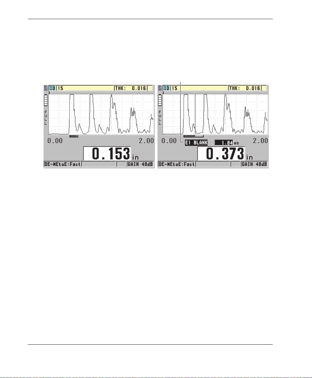
DMTA-10022-01EN, Rev. C, January 2015
Poor manual measurement Good manual measurement
[WAVE ADJ] parameter
a) In the measurement screen, press [SETUP], and then select MEAS.
b) In the MEAS menu, set the MEAS OPTION to MANUAL E-TO-E, and then
press [MEAS].
2. Press [GAIN/WAVE ADJ].
The wave adjustment parameter appears (see Figure 6-5 on page 74).
Figure 6-5 Comparing manual measurements
3. Use the [] and [] keys to select either the EXT BLANK or the E1 BLANK
parameter.
4. Use the [] and [] keys to adjust the value to exclude unwanted peaks and to
detect the desired echoes.
6.2.2 Dual Element Transducer Selection in Echo-to-Echo Modes
Although the optional Echo-to-Echo modes work with all the 45MG dual element
transducers, Olympus recommends using specific transducers for particular thickness
ranges in steel parts (see Table 4 on page 75).
Chapter 6
74
Page 85
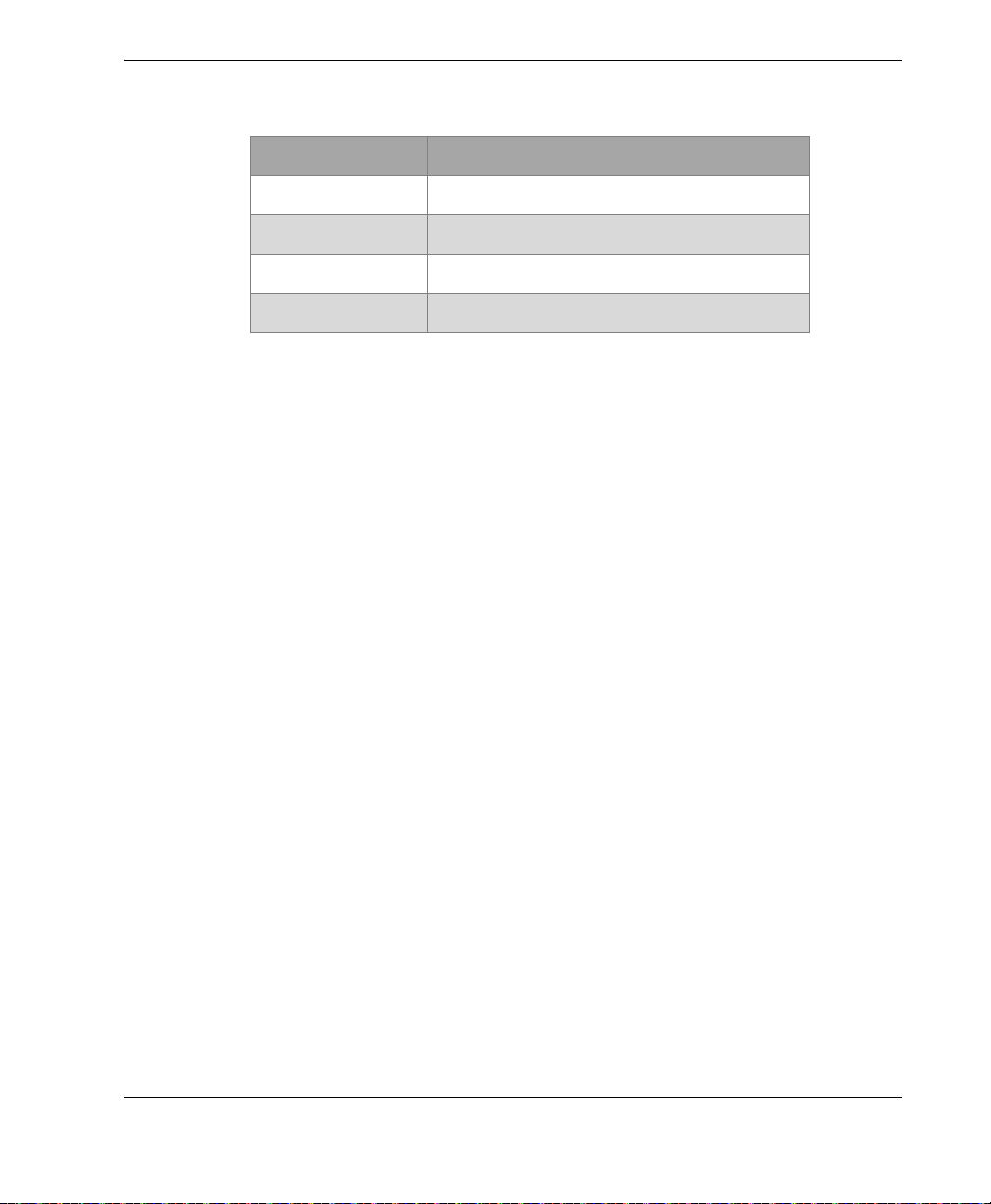
DMTA-10022-01EN, Rev. C, January 2015
Table 4 Recommended transducers for various steel thickness ranges
Transducer type
Thickness range
a
D798 1.5 mm to 7.6 mm (0.060 in. to 0.300 in.)
D790/791 2.5 mm to 51 mm (0.100 in. to 2.00 in.)
D797 12.7 mm to 127 mm (0.500 in. to 5.00 in.)
D7906 2.5 mm to 51 mm (0.100 in. to 2.00 in.)
a. Thickness ranges are dependent on the transducer type, material
conditions, and temperature.
In some cases, an error can occur if you are using a D790 transducer to measure
thicknesses above 18 mm (0.7 in.). Typically, this error is due to a mode-converted
shear-wave echo that may appear before the second back-wall echo. If this unwanted
echo is larger than the second back-wall echo, the gage measures the distance to it,
which produces a thinner reading.
You can usually distinguish the unwanted shear-wave echo from the correct back-wall
echo by examining the waveform display. The distance between the first and the
second back-wall echoes is the same as the distance between the zero thickness point
and the first back-wall echo. If there is an echo between the first two back-wall echoes,
it is probably a mode-converted shear-wave echo. Use the manual echo-to-echo
detection mode techniques, and manually adjust the E1 blank to eliminate this error
(see “Blanking Adjustments in Manual Echo-to-Echo Detection Mode” on page 73).
Using the D797 transducer beyond 18 mm (0.7 in.) helps eliminate the possibility of
this error.
In some cases, the second or third back-wall echo is smaller in amplitude than
subsequent echoes, which causes the instrument to give a double or triple reading. If
you are using a D790 transducer, this effect may occur around 5 mm (0.2 in.) on flat,
smooth steel samples. If this occurs, it is clearly visible on the waveform display, and
you can work around it using the manual Echo-to-Echo detection mode, or by moving
the extended blank beyond the previously detected first echo.
When the 45MG cannot make an echo-to-echo reading, the LOS flag appears on the
screen. In this case, the waveform display shows that either no echoes are large
enough to be detected, or that only one echo is detectable. In the latter case, the Echoto-Echo detection bar begins at the detected echo, but extends indefinitely to the right.
Software Options 75
Page 86
DMTA-10022-01EN, Rev. C, January 2015
NOTE
Increase the gain value to make a good echo-to-echo reading. If this does not help, you
can still obtain an approximate measurement by returning to the standard echo
detection mode.
6.3 Measurements with Optional THRU-COAT, D7906, and D7908 Transducers
THRU-COAT is an optional function that measures the true metal thickness of coated
or painted parts. This function only requires a single back-wall echo, and is
recommended for heavy corrosion applications where the outside of the material is
coated or painted. If necessary, the measurement of the coating/paint layer can also be
calibrated to precisely measure the thickness of the coating/paint.
In order for the THRU-COAT function to work properly, the thickness of the coating
or paint must be at least 0.125 mm (0.005 in.) thick. The maximum coating/paint
thickness that THRU-COAT can measure is dependent on the type of coating, but
typically greater then 2 mm (0.080 in.).
If the THRU-COAT function does not display a coating thickness, or if the coating
thickness does not seem realistic, THRU-COAT may not be able to properly resolve
the coating thickness. In such cases, the user should try a different measurement
mode, like Echo-to-Echo or standard.
6.3.1 Enabling the THRU-COAT Function
The THRU-COAT function is only available when you connect a THRU-COAT
transducer (P/N: D7906 [U8450005] or D7908 [U8450008]) to the 45MG.
To enable the THRU-COAT function
1. Connect a THRU-COAT transducer to the 45MG.
2. Turn on the instrument.
3. Wipe the couplant off the transducer tip.
4. Press [2nd F], [CAL ZERO] (Do ZERO) (see Figure 6-6 on page 77).
Chapter 6
76
Page 87
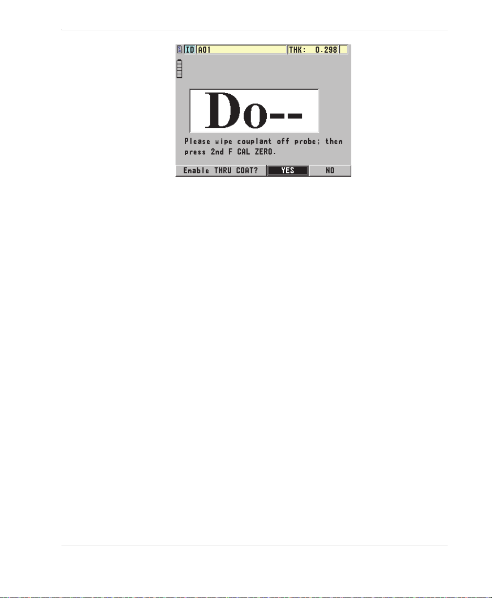
DMTA-10022-01EN, Rev. C, January 2015
Figure 6-6 Opening the THRU-COAT setup dialog box
5. Select YES to answer the Enable THRU COAT? prompt.
6.3.2 Performing a THRU-COAT Calibration
The calibration procedure for a THRU-COAT probe is similar to the procedure for
other probes. As for a normal calibration, you need two uncoated samples with
accurately known thin and thick thicknesses in order to perform the calibration
procedure below. The difference is that towards the end of the procedure, you can
press [CAL VEL] a second time to calibrate the coating thickness measurement on a
sample with an accurately known coating thickness.
To perform a THRU-COAT calibration
1. Ensure that the THRU-COAT function is enabled (see “Enabling the THRU-
COAT Function” on page 76).
2. Couple the transducer to the thick sample.
3. Press [CAL VEL].
4. Once the reading is stable, press [ENTER].
5. Using the arrow keys, edit the thickness value to match the known thickness of
the sample.
6. Couple the transducer to the thin sample.
7. Press [CAL ZERO].
8. Once the reading is stable, press [ENTER].
Software Options 77
Page 88
DMTA-10022-01EN, Rev. C, January 2015
NOTE
9. Using the arrow keys, edit the thickness value to match the known thickness of
the sample.
10. If the coating thickness-measurement accuracy is important to your application,
perform the following actions (omitting this step does not affect the accuracy of
the metal thickness measurement):
a) Press [CAL VEL] again.
b) Couple the transducer to the coated sample.
c) Once the reading is stable, press [ENTER].
d) Using the arrow keys, edit the thickness value to match the known coating
thickness of the coated sample.
11. Press [MEAS] to complete the calibration.
Pressing [2nd F], [CAL VEL] (VEL) opens the VELOCITY screen, in which you can
see and edit the calibrated metal sound velocity. Pressing [2nd F], [CAL VEL] (VEL)
again opens the VELOCITY screen for the calibrated sound velocity through the
coating.
6.4 Waveform Software Option
The live Waveform option for the 45MG allows the user to view the live ultrasonic
waveform in order to aid alignment of the transducer during difficult applications.
When this option is activated, the user can switch between the standard thickness
display (see Figure 6-7 on page 79) and the optional waveform thickness display (see
Figure 6-8 on page 80).
Other waveform setup features are listed below:
• [GAIN/WAVE ADJ] allows the user to make setup adjustments that are not
available in standard mode.
— With dual element transducers (see “Using Advanced Gaging Features” on
page 149):
•Manually adjust the GAIN in 1 dB increments.
• Set an extended blank.
• Set an Echo1 blank in Manual Echo-to-Echo mode.
Chapter 6
78
Page 89
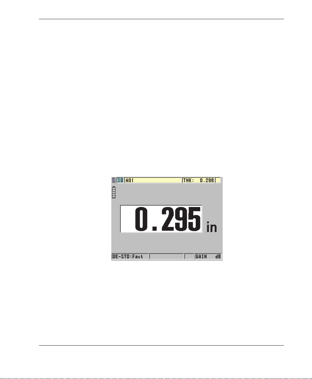
DMTA-10022-01EN, Rev. C, January 2015
• Adjust the waveform range and delay.
— With the Single Element transducer option (see “Custom Setups for Single
Element Transducers” on page 165):
• Adjust the pulse-receive parameters (TVG gain and blanks)
• Create custom single element transducer setups.
• Adjust the waveform range and delay.
• Auto Zoom: This mode automatically adjusts the range and delay so that the
measured echo is always on-screen.
• The waveform rectification: Enables the user to switch the waveform between Full
wave, Half+, Half−, and RF display.
• Waveform Fill: Enables the user to show the filled-in waveform. This feature is
not available for RF rectification mode.
• Assigns the [SAVE] key to:
Save only the thickness value.
OR
Save the thickness and waveform (only available when the Datalogger software
option is also purchased).
Figure 6-7 Standard display
Software Options 79
Page 90
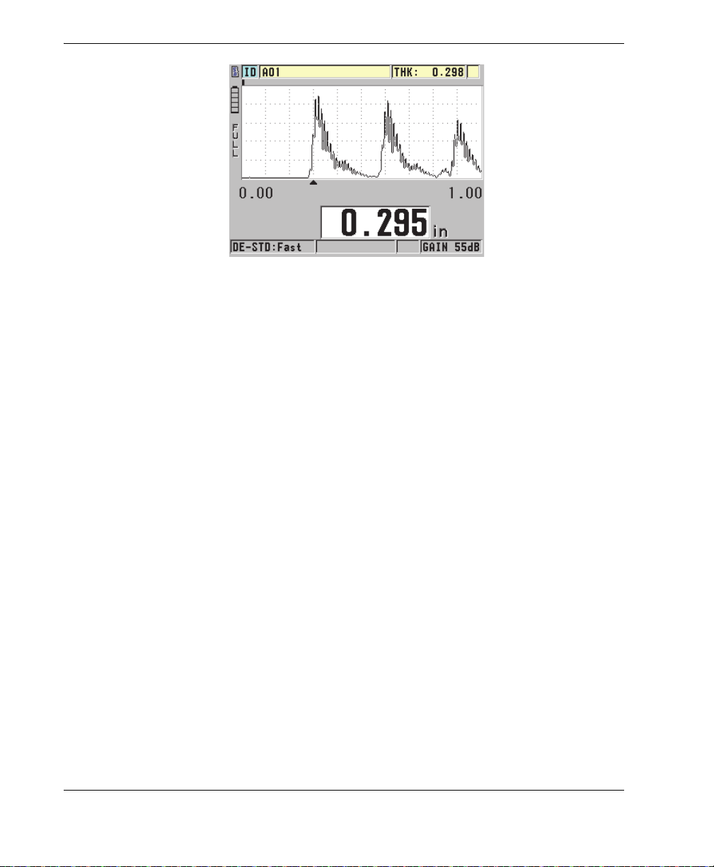
DMTA-10022-01EN, Rev. C, January 2015
Figure 6-8 Waveform display
To activate the waveform
1. In the measurement screen, press [SETUP], and then select DISPLAY.
2. Set WAVEFORM ENABLE to ON.
6.4.1 Waveform Rectification
The rectification mode determines the way in which the ultrasonic echoes are
represented on the waveform display (see Figure 6-9 on page 81). The rectification
mode does not affect the thickness measurement in any way. The rectification
indicator (FULL, POS, NEG, or RF) appears on the left edge of the waveform display.
In the measurement screen, press [SETUP], and then select DISPLAY to access the
WAVEFORM RECTIFICATION parameter.
Chapter 6
80
Page 91
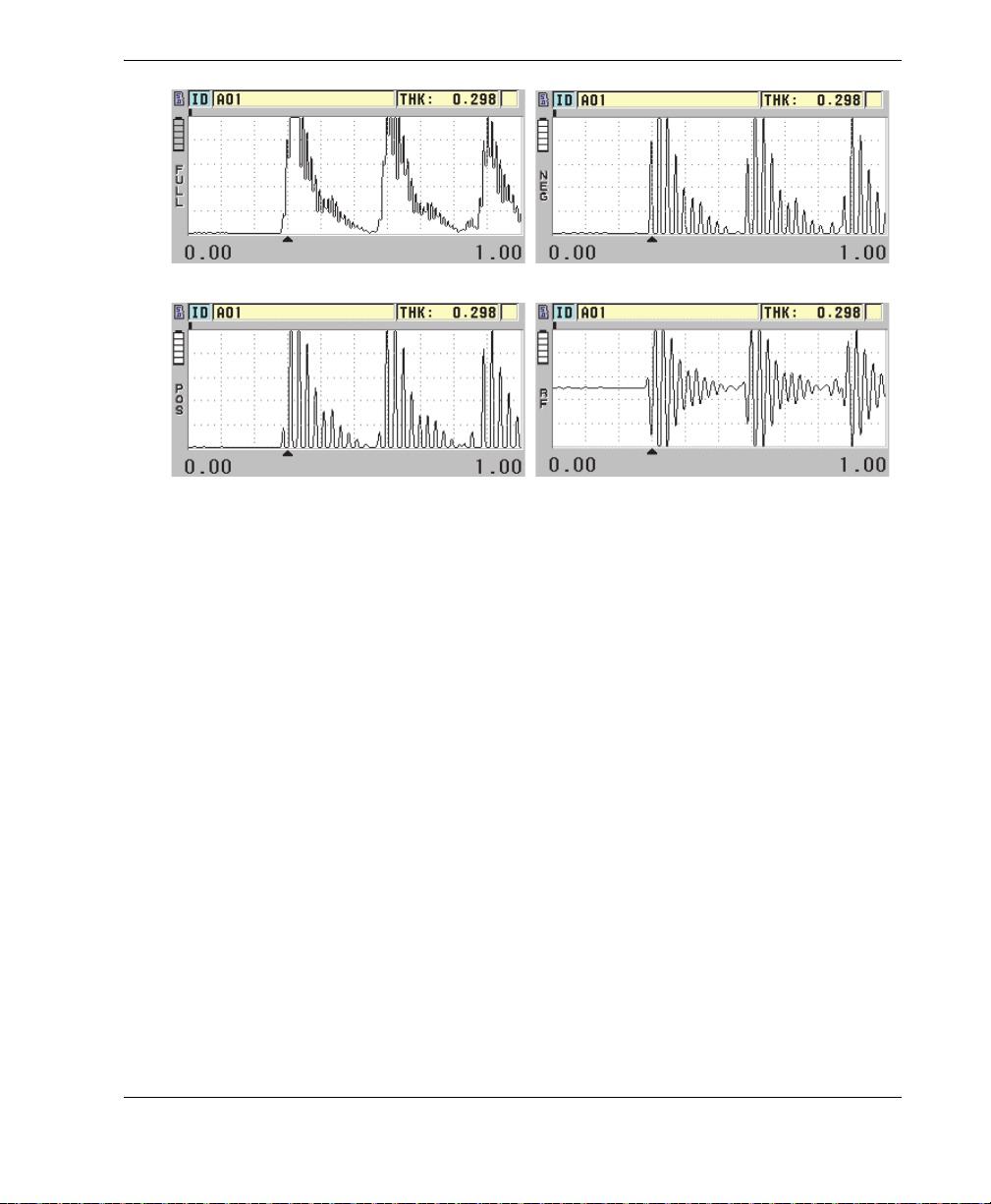
Figure 6-9 Examples of the rectification modes
Full
Half−
Half+
RF
The available rectification modes are:
DMTA-10022-01EN, Rev. C, January 2015
FULL
This mode shows the negative portion of the echo folded around the baseline, so
that both positive and negative waveform lobes are displayed. This mode
provides the best overall representation of position and magnitude for most
thickness-measurement applications. FULL is the default mode for dual element
transducers.
HALF− (NEG indicator)
This mode shows negative waveform lobes as positive, and does not show the
positive lobes.
HALF+ (POS indicator)
This mode shows positive waveform lobes, and does not show the negative
waveform lobes.
RF
This mode shows negative and positive lobes on either side of the baseline. RF is
the default mode for single element transducers.
Software Options 81
Page 92
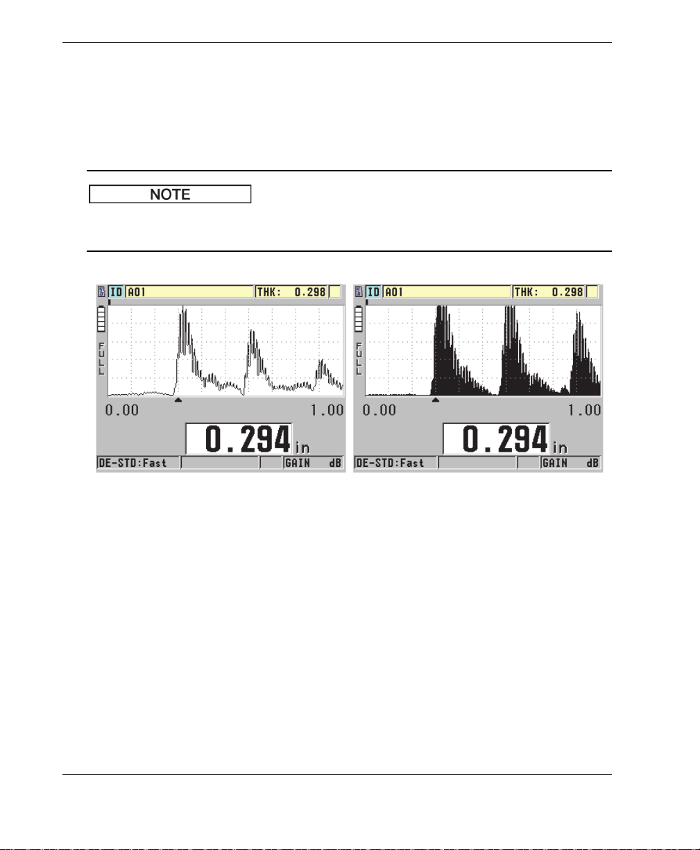
DMTA-10022-01EN, Rev. C, January 2015
NOTE
Outline waveform
Filled-in waveform
6.4.2 Waveform Trace
The 45MG can display the waveform trace as a line (OUTLINE), or as a FILLED area
(see Figure 6-10 on page 82). In the measurement screen, press [SETUP], and then
select DISPLAY to access the WAVE FORM TRA CE parameter.
A filled-in waveform trace is only possible when the waveform rectification is set to
FULL, HALF+, or HALF−.
Figure 6-10 Examples of waveform trace modes
6.4.3 Range of the Waveform Display
The range of the waveform display (see Figure 6-11 on page 83) is the distance
spanned by the horizontal axis of the waveform display. The left end of the horizontal
axis, the delay, is generally set to zero. The delay value can be manually adjusted to
change the starting point of the range (see “Adjusting the Delay Value” on page 84),
and to select the end point of the range (see “Selecting the Range Value” on page 83).
You can also activate the zoom function to automatically set the delay and the range
values for optimum visualization of the echo (see “Activating the Zoom Function
(Available Only with the Waveform Option)” on page 84).
Chapter 6
82
Page 93
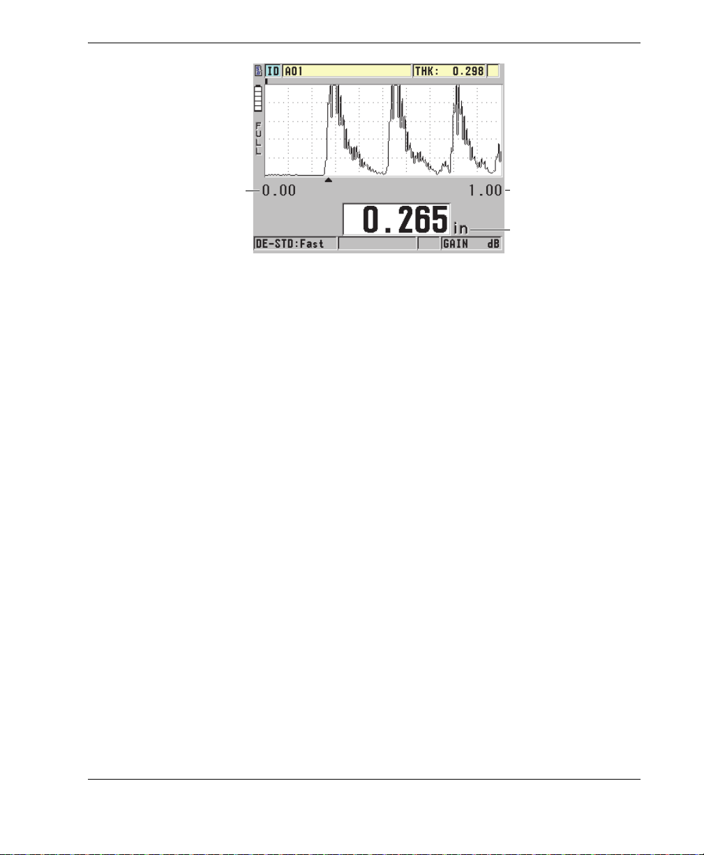
DMTA-10022-01EN, Rev. C, January 2015
Selectable range value
Adjustable delay value
Units
Figure 6-11 The range of the waveform display
6.4.3.1 Selecting the Range Value
There are fixed ranges available for each transducer frequency. The available ranges
are also dependent on material sound velocity. These selectable ranges let you adjust
the thickness span of the waveform display to show only the thickness range being
measured, and thus obtain maximum waveform resolution for each application. The
range setting affects only the waveform display. It is possible to make measurements
even when the display range does not show the detected echo from which the
thickness is measured. The range cannot be manually set while the zoom is active.
To select the range value
1. In the measurement screen, press the [] and [] keys to adjust the range.
The waveform range changes to the next higher available range.
2. Continue pressing the [] key to select the next higher range, or press the [] key
to select the next lower range.
The range value recycles to the minimum range value following the maximum
value.
Software Options 83
Page 94
DMTA-10022-01EN, Rev. C, January 2015
NOTE
NOTE
When the [GAIN/WAVE ADJ] parameters are active, the range and delay become
items in the parameter list. Use the [] and [] keys to highlight the range parameter,
and the [] and [] keys to adjust the range. Press [MEAS] to stop adjusting the
range.
6.4.3.2 Adjusting the Delay Value
The delay of the waveform display adjusts the beginning of the horizontal span. The
delay can be adjusted to display the waveform of interest in the center of the
waveform display. This function is very useful when using delay line or immersion
transducers, or when measuring thick material, in order to ensure that the measured
echoes can be seen in greater detail.
To adjust the delay value
In the measurement screen, press the [] and [] keys to adjust the delay.
When the [GAIN/WAVE ADJ] parameters are active, the range and delay become
items in the parameter list. Use the [] and [] keys to highlight the delay parameter,
and the [] and [] keys to adjust the delay. Press [MEAS] to stop adjusting the delay.
6.4.3.3 Activating the Zoom Function (Available Only with the Waveform Option)
The zoom function automatically and dynamically sets the delay and range values to
optimally track and show the detected echo in the waveform display.
To activate the zoom function
1. In the measurement screen, press [SETUP], and then select DISPLAY.
2. In the DISPLAY screen, set the ZOOM OPTION to ON.
The zoom flag ( ) appears on the lower right side of the waveform display, below
the range parameter.
Chapter 6
84
Page 95
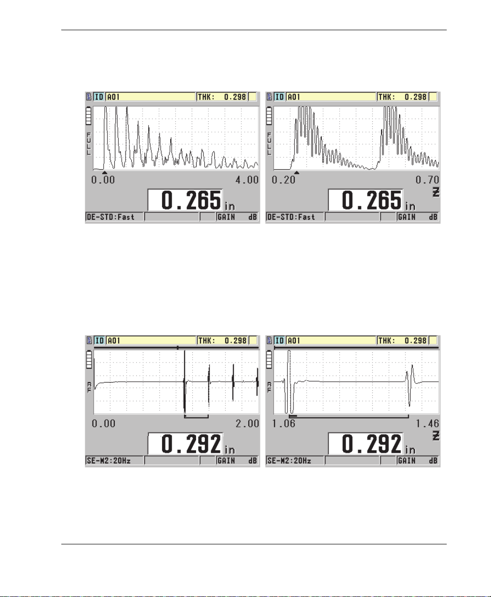
DMTA-10022-01EN, Rev. C, January 2015
Normal display Zoomed display
Normal display Zoomed display
The resulting zoomed waveform depends on the current measurement mode. The
zoom for D79X dual element transducers and mode 1 single element transducers
centers the first back-wall echo on the screen (see Figure 6-12 on page 85).
Figure 6-12 Comparing the normal and zoomed display in mode 1
The zoom with single element transducers in mode 2 adjusts the waveform range and
delay so that the interface echo and the first back-wall echo appear on the waveform
display (see Figure 6-13 on page 85).
Figure 6-13 Comparing the normal and zoomed display in mode 2
Software Options 85
Page 96
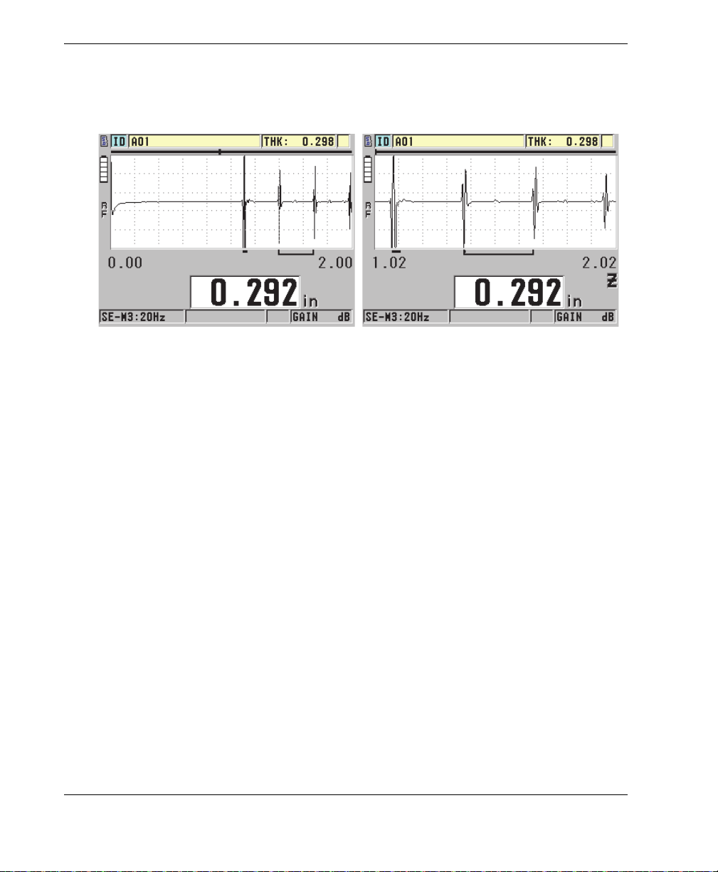
DMTA-10022-01EN, Rev. C, January 2015
Normal display Zoomed display
The zoom with single element transducers in mode 3 adjusts the waveform range and
delay so that the interface echo and the second measured back-wall echo appear on
the waveform display (see Figure 6-14 on page 86).
Figure 6-14 Comparing the normal and zoomed display in mode 3
To deactivate the zoom function
1. In the measurement screen, press [SETUP], and then select DISPLAY.
2. In the DISPLAY screen, set the ZOOM OPTION to OFF.
6.5 Single Element and High Resolution Option
The optional Single Element High Resolution software allows the 45MG to use single
element direct contact, delay line, and immersion transducers. This enables the 45MG
to be used for precision thickness gaging applications. When this option is activated,
the user can select from a set of default single element transducer setups, or create and
store/recall customers’ single element setups.
The 45MG is not able to automatically recognize which single element transducer is
connected. As such, the appropriate default or customer setup must be recalled for
the single element transducer being used.
Chapter 6
86
Page 97

DMTA-10022-01EN, Rev. C, January 2015
6.5.1 Recalling Single Element Transducer Setups
The procedure for recalling single element transducer setups is explained in “Setting
Up the Transducer” on page 51.
6.5.2 Creating Custom Single Element Transducer Setups
For more information about how to create custom single element transducer setups,
please refer to “Custom Setups for Single Element Transducers” on page 165.
6.5.3 High-Resolution Thickness
The 45MG has the ability to display thickness values with its standard resolution of
0.01 mm (or 0.001 in.), and its low resolution of 0.1 mm (or 0.01 in.). These resolutions
are adequate for most ultrasonic thickness-measurement applications.
For single element transducers, the high-resolution software option provides the
added ability to display thickness readings with a high resolution of 0.001 mm (or
0.0001 in.). High resolution is not available for all transducers and measurement
modes, and is also limited to the maximum thickness. Although the 45MG is able to
display thickness readings in high resolution, the measurement accuracy is highly
dependent on the material, geometry, surface condition, and temperature, and also
needs to be determined on a case-by-case sample evaluation basis.
High resolution is available for the following transducers and measurement
conditions:
• Single element transducer in the frequency range of 2.25 MHz to 30.0 MHz
• Thickness measurement below 100 mm (or 4.00 in.)
High resolution is not available for the following transducers or measurement
conditions:
• Dual element transducers
• Low-frequency transducers with a frequency below 2.25 MHz
• Thickness ranges over 100 mm (or 4.00 in.)
• Once activated, the high-resolution selection appears in the resolution
selection list (see “Changing the Thickness Resolution” on page 50).
Software Options 87
Page 98
DMTA-10022-01EN, Rev. C, January 2015
NOTE
6.6 High-Penetration Software Option
The 45MG high-penetration software option coupled with low-frequency single
element transducers (down to 0.5 MHz) allows you to make thickness, material sound
velocity, and time-of-flight measurements on materials such as composites, fiberglass,
plastic, rubber, and cast metals that are difficult or impossible to measure using
standard ultrasonic instruments. The M2008 [U8415001] transducer is a special lowfrequency transducer used to measure the thickness of thick fiber-reinforced polymer
(FRP) and composite materials.
With a M2008 transducer only, press [2nd F], [CAL ZERO] (Do ZERO) at any time to
auto-adjust the zero offset and compensate for temperature changes in the delay line.
To use the high-penetration software option with the M2008 transducer
1. Ensure that the high-penetration software option is activated (see “Activating
Software Options” on page 68 for details).
2. Connect the M2008 transducer to the T/R 1 connector at the top of the 45MG.
3. Press [2nd F], [FREEZE] (XDCR RECALL).
4. In the menu, select DEFAULT HP SINGLE ELEMENT.
5. In the DEFAULT HP SINGLE ELEMENT screen, highlight the default transducer
setup for the M2008 (DEFP1-0.5-M2008), or any custom setup that uses the M2008
transducer.
6. Press [MEAS] to return to the measurement screen with the recalled transducer
setup.
7. Wipe the couplant off the transducer tip.
8. Press [2nd F], [CAL ZERO] (Do ZERO).
9. Perform the material sound velocity and zero calibration (see “Calibrating the
Instrument” on page 55).
6.7 Datalogger Option
This section describes how to use the 45MG internal datalogger to organize your data.
Chapter 6
88
Page 99
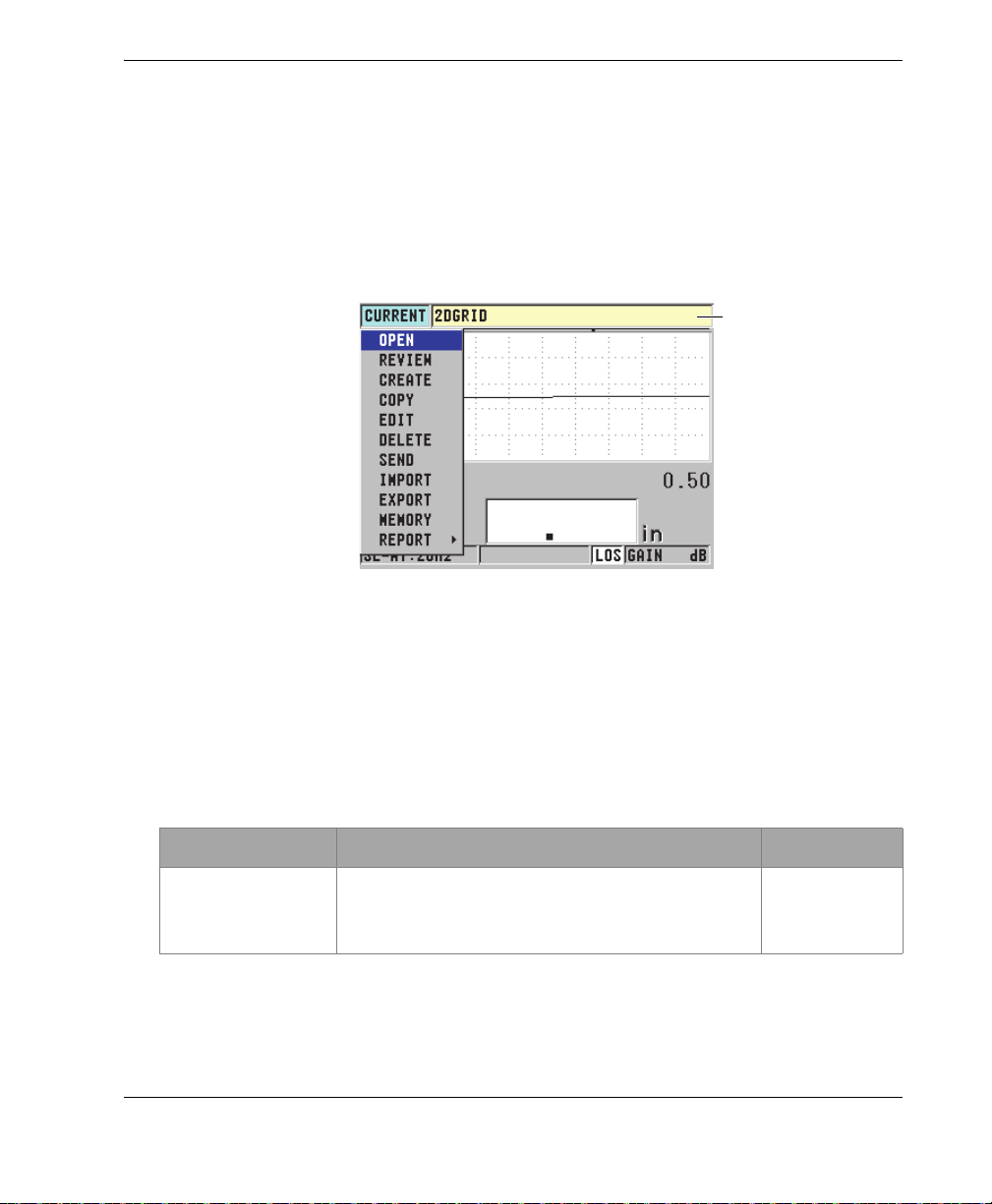
DMTA-10022-01EN, Rev. C, January 2015
Name of the active file
6.7.1 Datalogger
The 45MG datalogger is a file-based system, in which one file is opened at a time. The
active file stores a measurement at a thickness-measurement location ID. Each time
you press [SAVE], the displayed value is saved to the active file at the current ID. The
ID is automatically incremented for the next measurement. When you press [FILE],
the name of the active file appears in the ID bar above the menu (see Figure 6-15 on
page 89).
Figure 6-15 The active file name appears in the ID bar
The file also contains header parameters that can be defined to better describe the
content of the file. In the file, you can organize the ID range, select the data format,
and select the saved data. Table 5 on page 89 summarizes the contents of a file, and
indicates where you can find more information.
Table 5 File contents summary
Contents Description See section
Header Extra parameters to describe the contents and
the context of the data
Software Options 89
“Creating a
Data File” on
page 92
Page 100
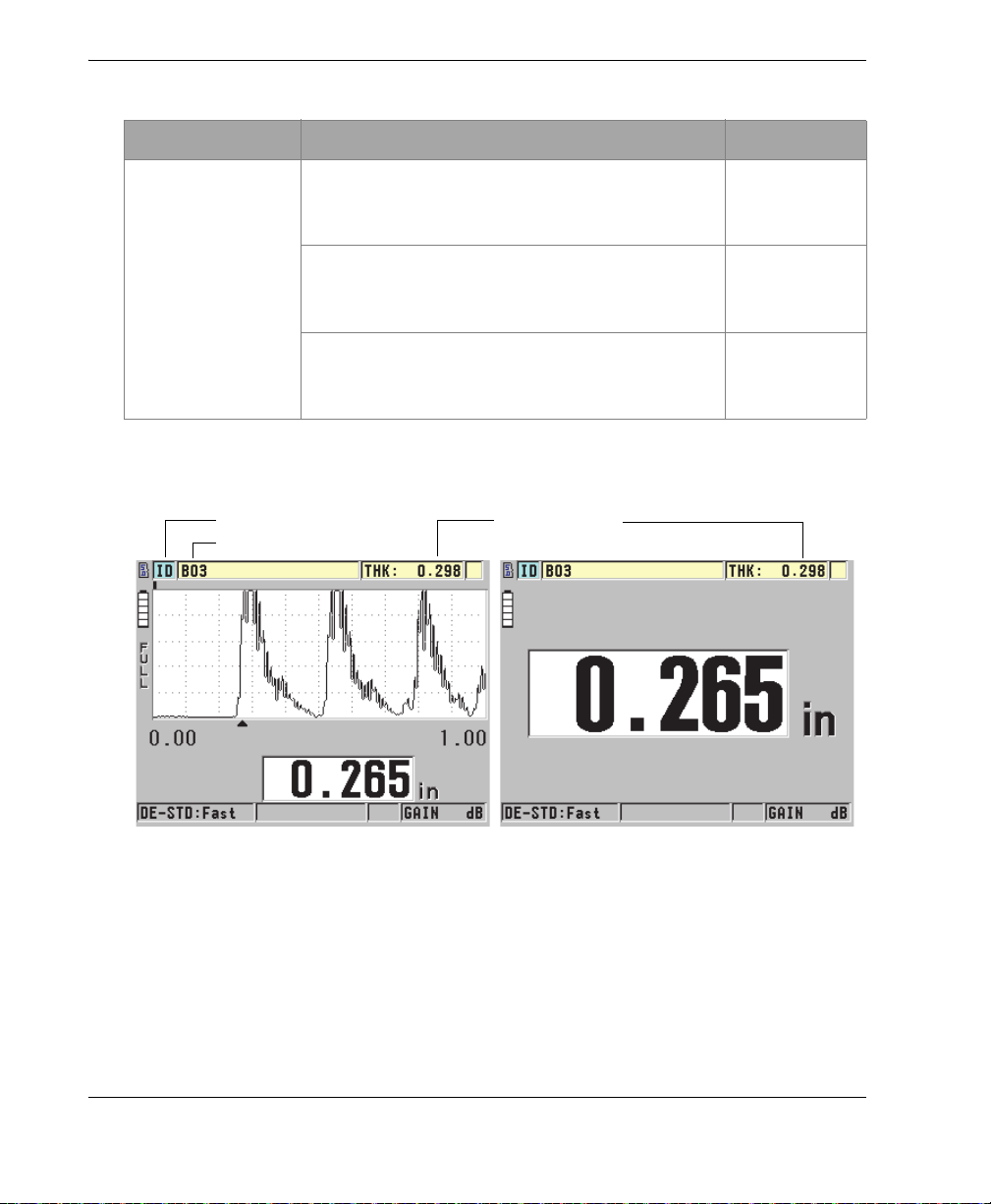
DMTA-10022-01EN, Rev. C, January 2015
ID number
Previous thickness
ID bar
Table 5 File contents summary (continued)
Contents Description See section
Measurement
data
You can identify the datalogger parameters in the ID bar at the top of the
measurement screen (see Figure 6-16 on page 90).
Organized by predefined IDs arranged by file
types
Data format defined by the file data mode “File Data
Saved data (thickness measurement with or
without the waveform) configured using the
setup menu
“Data File
Types” on
page 93
Modes” on
page 104
“Saving
Data” on
page 65
Figure 6-16 Identifying datalogger parameters
With each measurement, the 45MG also stores a complete description of the
measurement conditions. Table 6 on page 91 describes the additional data stored with
each thickness measurement and with each waveform.
Chapter 6
90
 Loading...