

Olympus 27MG User Manual

27MG
Ultrasonic Thickness Gage
User’s Manual
DMTA-10043-01EN — Rev. C
July 2016
This instruction manual contains essential information on how to use this Olympus product safely and effectively.
Before using this product, thoroughly review this instruction manual. Use the product as instructed.
Keep this instruction manual in a safe, accessible location.

Olympus Scientific Solutions Americas, 48 Woerd Avenue, Waltham, MA 02453, USA
Copyright © 2013, 2014, 2016 by Olympus. All rights reserved. No part of this publication
may be reproduced, translated, or distributed without the express written permission of
Olympus.
This document was prepared with particular attention to usage to ensure the accuracy of the
information contained therein, and corresponds to the version of the product manufactured
prior to the date appearing on the title page. There could, however, be some differences
between the manual and the product if the product was modified thereafter.
The information contained in this document is subject to change without notice.
Part number: DMTA-10043-01EN
Rev. C
July 2016
Printed in the United States of America
All brands are trademarks or registered trademarks of their respective owners and third
party entities.

DMTA-10043-01EN, Rev. C, July 2016
Table of Contents
List of Abbreviations ...................................................................................... vii
Labels and Symbols ........................................................................................... 1
Important Information — Please Read Before Use ..................................... 5
Intended Use .......................................................................................................................... 5
Instruction Manual ................................................................................................................ 5
Instrument Compatibility ..................................................................................................... 5
Repair and Modification ....................................................................................................... 6
Safety Symbols ....................................................................................................................... 6
Safety Signal Words ............................................................................................................... 7
Note Signal Words ................................................................................................................. 7
Warnings ................................................................................................................................. 8
Battery Precautions ................................................................................................................ 9
Equipment Disposal .............................................................................................................. 9
CE (European Community) ................................................................................................. 9
WEEE Directive .................................................................................................................... 10
China RoHS .......................................................................................................................... 10
Korea Communications Commission (KCC) ................................................................... 11
EMC Directive Compliance ................................................................................................ 11
FCC (USA) Compliance ...................................................................................................... 11
ICES-001 (Canada) Compliance ........................................................................................ 12
Warranty Information ......................................................................................................... 12
Technical Support ................................................................................................................ 13
1. Instrument Description ............................................................................. 15
1.1 Product Description .................................................................................................. 15
1.2 Environmental Ratings ............................................................................................ 16
1.3 Instrument Hardware Components ....................................................................... 16
Table of Contents iii

DMTA-10043-01EN, Rev. C, July 2016
1.4 Connectors ................................................................................................................. 17
1.5 Keypad Functions ..................................................................................................... 18
2. 27MG Power Requirements ..................................................................... 23
2.1 Power Indicator ......................................................................................................... 23
2.2 Batteries ...................................................................................................................... 24
3. Software User Interface Elements ........................................................... 27
3.1 Measurement Screen ................................................................................................ 27
3.2 Parameter Screens ..................................................................................................... 28
4. Initial Setup ................................................................................................ 31
5. Standard Calibration Measurement ....................................................... 35
5.1 Introduction ............................................................................................................... 35
5.2 Transducer Zero Compensation ............................................................................. 36
5.3 Velocity and Zero Calibration ................................................................................. 36
5.4 Material Velocity Calibration .................................................................................. 37
5.5 Zero Calibration ........................................................................................................ 39
6. Measurements ............................................................................................. 41
7. Additional 27MG Gaging Features ........................................................ 43
7.1 Adjusting the Backlight ............................................................................................ 44
7.2 Activating the Freeze Mode ..................................................................................... 45
7.3 Adjusting the Gain .................................................................................................... 45
7.4 Optimizing Material Gain Sensitivity .................................................................... 45
7.5 Restoring the Default Gain ...................................................................................... 46
7.6 Configuring the Measurement Setup ..................................................................... 46
7.7 Configuring the System Setup ................................................................................ 50
7.8 Activating High/Low Alarms .................................................................................. 52
7.9 Activating Diff Mode ................................................................................................ 53
7.10 Resetting the Instrument Parameters ..................................................................... 53
8. Specifications .............................................................................................. 57
9. Theory of Operation .................................................................................. 59
10. Application Notes ...................................................................................... 61
10.1 Factors Affecting Performance and Accuracy ...................................................... 61
Table of Contents
iv

DMTA-10043-01EN, Rev. C, July 2016
10.2 Transducer Selection ................................................................................................. 63
10.3 High Temperature Measurements ......................................................................... 66
11. Maintenance and Troubleshooting ........................................................ 69
11.1 Routine Care and Maintenance .............................................................................. 69
11.2 Transducers Maintenance ........................................................................................ 69
11.3 Error Messages .......................................................................................................... 70
11.4 Battery Problems ....................................................................................................... 70
11.5 Setup (Do--) Problems .............................................................................................. 70
11.6 Measurement Problems Diagnostic ....................................................................... 70
11.7 Self Diagnostics ......................................................................................................... 71
11.8 Gage Performance Tests ........................................................................................... 73
11.9 Repair Service ............................................................................................................ 75
11.10 Replacement Parts, Optional Parts, and Equipment ........................................... 75
Appendix: Sound Velocities .......................................................................... 77
List of Figures ................................................................................................... 81
List of Tables ..................................................................................................... 83
Index ................................................................................................................... 85
Table of Contents
v

DMTA-10043-01EN, Rev. C, July 2016
Table of Contents
vi

List of Abbreviations
DIAG diagnostic
DIFF differential
EFUP environment-friendly use period
IP Ingress Protection
LOS loss-of-signal
Max maximum
Min minimum
NiMH nickel-metal hydride
PDF portable document format
T/R transmit/receive
USB universal serial bus
DMTA-10043-01EN, Rev. C, July 2016
List of Abbreviations vii

DMTA-10043-01EN, Rev. C, July 2016
List of Abbreviations
viii
DMTA-10043-01EN, Rev. C, July 2016
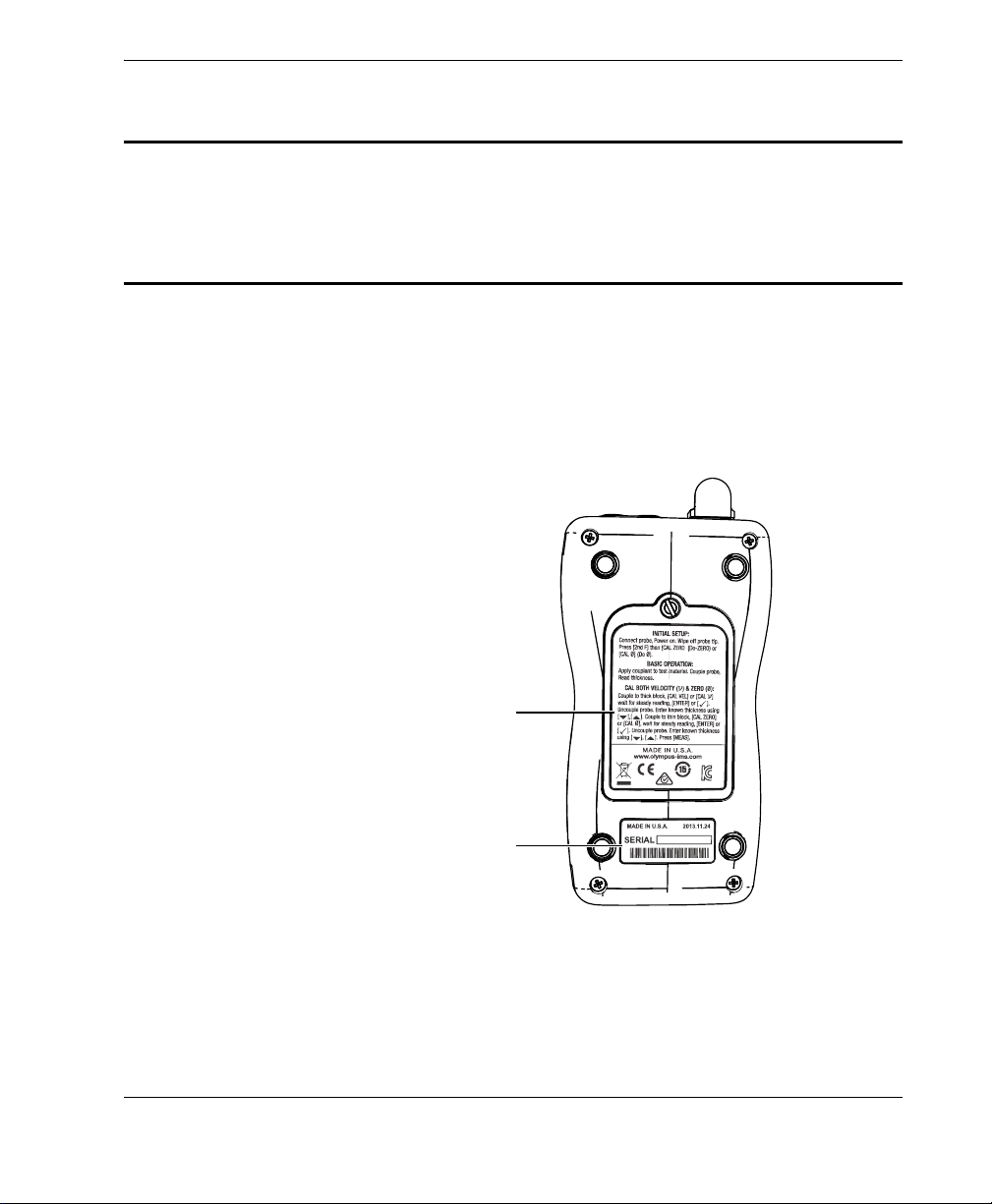
Location of serial number label
(see Table 1 on page 2)
Location of instruction and rating
label (see Table 1 on page 2)
Labels and Symbols
Safety-related labels and symbols are attached to the instrument at the locations
shown in Figure i-1 on page 1. The symbols are described in Table 1 on page 2 and
Table 2 on page 3. If any or all of the labels or symbols are missing or illegible, please
contact Olympus.
Figure i‑1 Labels locations
Labels and Symbols
1
DMTA-10043-01EN, Rev. C, July 2016
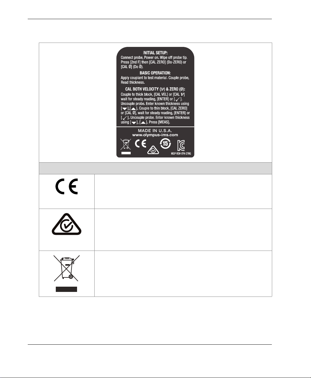
Table 1 Content of the instruction and rating label
The CE marking is a declaration that this product conforms to
all the applicable directives of the European Community. See
the Declaration of Conformity for details. Contact your Olympus
representative for more information.
Content
Labels and Symbols
2
The regulatory compliance mark (RCM) label indicates that
the product complies with all applicable standards, and has
been registered with the Australian Communications and
Media Authority (ACMA) for placement on the Australian
market.
The WEEE symbol indicates that the product must not be
disposed of as unsorted municipal waste, but should be
collected separately.
DMTA-10043-01EN, Rev. C, July 2016
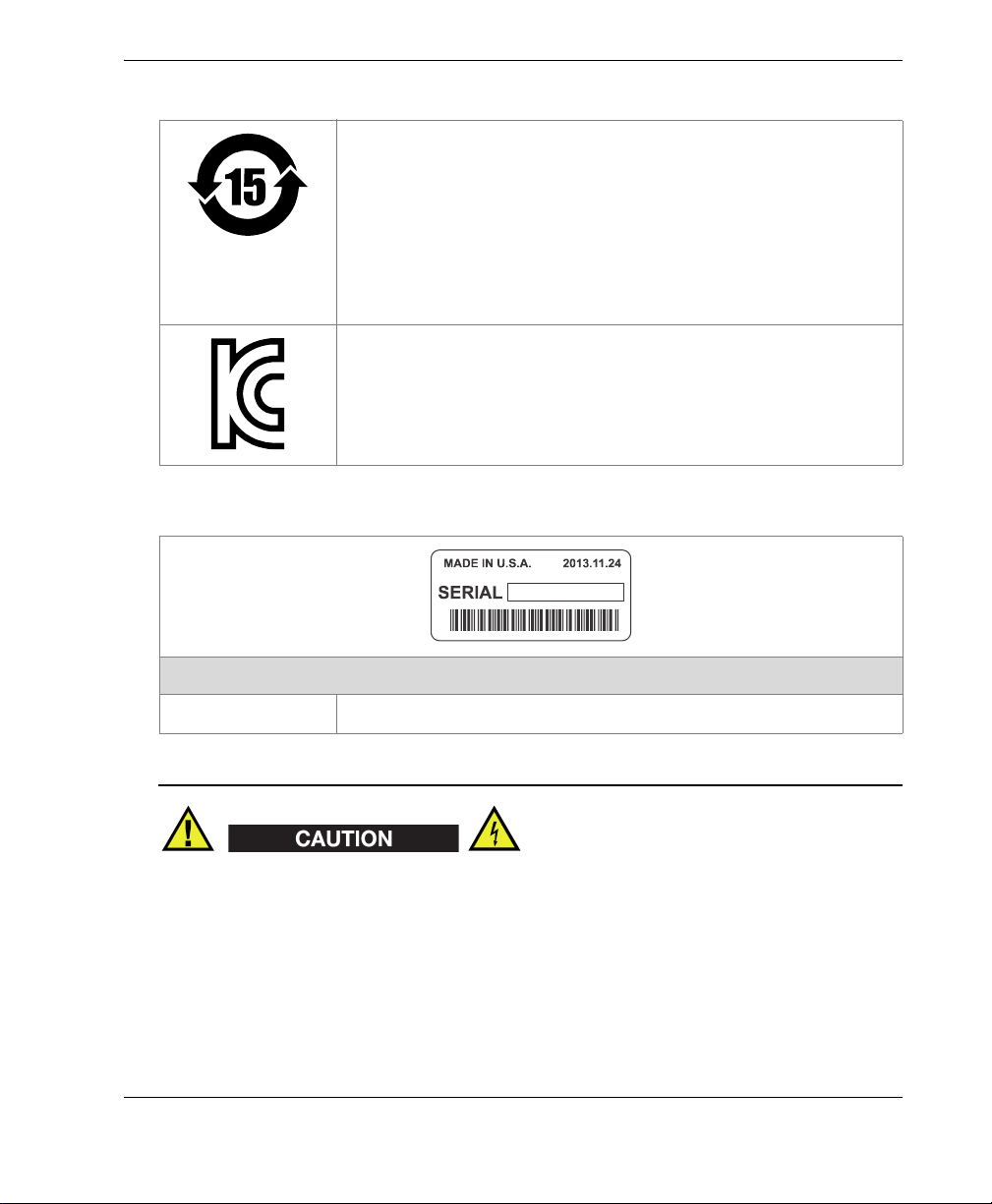
Table 1 Content of the instruction and rating label (continued)
The China RoHS mark indicates the product’s EnvironmentFriendly Use Period (EFUP). The EFUP is defined as the
number of years for which listed controlled substances will not
leak or chemically deteriorate while in the product. The EFUP
for the 27MG has been determined to be 15 years. Note: The
Environment-Friendly Use Period (EFUP) is not meant to be
interpreted as the period assuring functionality and product
performance.
Seller and user shall be noticed that this equipment is suitable
for electromagnetic equipment for office work (class A) and it
can be used outside home.
The MISP code for the 27MG instrument is the following:
MSIP-REM-OYN-27MG
Table 2 Content of the serial number label
Content
SERIAL The serial number.
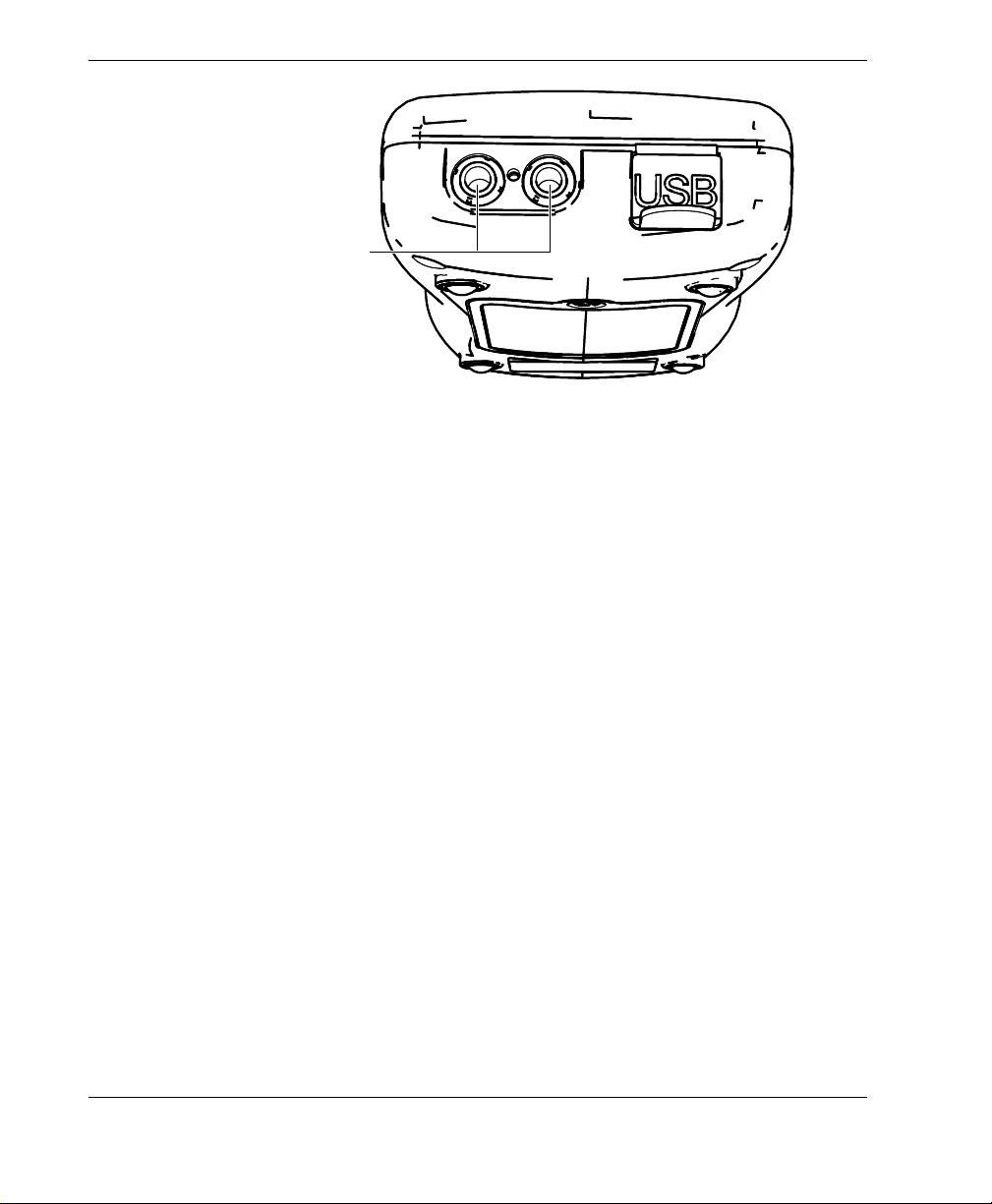
To avoid the risk of electric shock, do not touch the inner conductor of the
Transmit/Receive (T/R) T/R1 and T/R2 connectors. Up to 150 V can be present on the
inner conductors shown in Figure i-2 on page 4.
Labels and Symbols
3
DMTA-10043-01EN, Rev. C, July 2016
T/R1 and T/R2
connectors inner
conductors
Figure i‑2 Risk of electrical shock on T/R connectors inner conductors
Labels and Symbols
4

DMTA-10043-01EN, Rev. C, July 2016
Important Information — Please Read Before Use
Intended Use
The 27MG is designed to perform nondestructive inspections on industrial and
commercial materials.
Do not use the 27MG for any purpose other than its intended use. It must never be
used to inspect or examine human or animal body parts.
Instruction Manual
This instruction manual contains essential information on how to use this Olympus
product safely and effectively. Before using this product, thoroughly review this
instruction manual. Use the product as instructed.
Keep this instruction manual in a safe, accessible location.
Instrument Compatibility
Contact Olympus for information concerning ancillary equipment.
Important Information — Please Read Before Use
5
DMTA-10043-01EN, Rev. C, July 2016
Always use equipment and accessories that meet Olympus specifications. Using
incompatible equipment could cause malfunction and/or equipment damage, or
injury.
Repair and Modification
The 27MG does not contain any user-serviceable parts. Opening the instrument might
void the warranty.
In order to prevent human injury and/or equipment damage, do not disassemble,
modify, or attempt to repair the instrument.
Safety Symbols
The following safety symbols might appear on the instrument and in the instruction
manual:
General warning symbol
This symbol is used to alert the user to potential hazards. All safety messages that
follow this symbol shall be obeyed to avoid possible harm or material damage.
High voltage warning symbol
This symbol is used to alert the user to potential electric shock hazards greater
than 1000 volts. All safety messages that follow this symbol shall be obeyed to
avoid possible harm.
Important Information — Please Read Before Use
6
DMTA-10043-01EN, Rev. C, July 2016
Safety Signal Words
The following safety symbols might appear in the documentation of the instrument:
The DANGER signal word indicates an imminently hazardous situation. It calls
attention to a procedure, practice, or the like, which, if not correctly performed or
adhered to, will result in death or serious personal injury. Do not proceed beyond a
DANGER signal word until the indicated conditions are fully understood and met.
The WARNING signal word indicates a potentially hazardous situation. It calls
attention to a procedure, practice, or the like, which, if not correctly performed or
adhered to, could result in death or serious personal injury. Do not proceed beyond a
WARNING signal word until the indicated conditions are fully understood and met.
The CAUTION signal word indicates a potentially hazardous situation. It calls
attention to an operating procedure, practice, or the like, which, if not correctly
performed or adhered to, may result in minor or moderate personal injury, material
damage, particularly to the product, destruction of part or all of the product, or loss of
data. Do not proceed beyond a CAUTION signal word until the indicated conditions
are fully understood and met.
Note Signal Words
The following safety symbols could appear in the documentation of the instrument:
The IMPORTANT signal word calls attention to a note that provides important
information, or information essential to the completion of a task.
Important Information — Please Read Before Use
7
DMTA-10043-01EN, Rev. C, July 2016
The NOTE signal word calls attention to an operating procedure, practice, or the like,
which requires special attention. A note also denotes related parenthetical
information that is useful, but not imperative.
The TIP signal word calls attention to a type of note that helps you apply the
techniques and procedures described in the manual to your specific needs, or
provides hints on how to effectively use the capabilities of the product.
Warnings
General Warnings
• Carefully read the instructions contained in this instruction manual prior to
turning on the instrument.
• Keep this instruction manual in a safe place for further reference.
• Follow the installation and operation procedures.
• It is imperative to respect the safety warnings on the instrument and in this
instruction manual.
• If the equipment is used in a manner not specified by the manufacturer, the
protection provided by the equipment could be impaired.
• Do not install substitute parts or perform any unauthorized modification to the
instrument.
• Service instructions, when applicable, are for trained service personnel. To avoid
the risk of electric shock, do not perform any work on the instrument unless
qualified to do so. For any problem or question regarding this instrument, contact
Olympus or an authorized Olympus representative.
• Do not touch the connectors directly by hand. Otherwise, a malfunction or electric
shock may result.
• Do not allow metallic foreign objects to enter the device through the connectors or
any other openings. Otherwise, a malfunction or electric shock may result.
Important Information — Please Read Before Use
8

DMTA-10043-01EN, Rev. C, July 2016
Battery Precautions
• Before disposing of a battery, check your local laws, rules, and regulations, and
follow them accordingly.
• Do not open, crush, or perforate batteries; doing so could cause injury.
• Do not incinerate batteries. Keep batteries away from fire and other sources of
extreme heat. Exposing batteries to extreme heat (over 50 °C [122 °F]) could result
in an explosion or personal injury.
• Do not drop, hit, or otherwise abuse a battery, as doing so could expose the cell
contents, which are corrosive and explosive.
• Do not short-circuit the battery terminals. A short circuit could cause injury and
severe damage to a battery, making it unusable.
• Do not expose a battery to moisture or rain; doing so could cause an electric
shock.
• Do not leave batteries in the 27MG unit during instrument storage.
Equipment Disposal
Before disposing of the 27MG, check your local laws, rules, and regulations, and
follow them accordingly.
CE (European Community)
This device complies with the requirements of both directive
2004/108/EC concerning electromagnetic compatibility and directive
2006/95/EC concerning low voltage. The CE marking indicates
compliance with the above directives.
Important Information — Please Read Before Use
9

DMTA-10043-01EN, Rev. C, July 2016
WEEE Directive
In accordance with European Directive 2002/96/EC on Waste Electrical
and Electronic Equipment (WEEE), this symbol indicates that the
product must not be disposed of as unsorted municipal waste, but
should be collected separately. Refer to your local Olympus distributor
for return and/or collection systems available in your country.
China RoHS
China RoHS is the term used by industry generally to describe legislation
implemented by the Ministry of Information Industry (MII) in the People’s Republic
of China for the control of pollution by electronic information products (EIP).
The China RoHS mark indicates the product’s EnvironmentFriendly Use Period (EFUP). The EFUP is defined as the number of
years for which listed controlled substances will not leak or
chemically deteriorate while in the product. The EFUP for the
27MG has been determined to be 15 years.
Note: The Environment-Friendly Use Period (EFUP) is not meant
to be interpreted as the period assuring functionality and product
performance.
本标志是根据 “ 电器电子产品有害物质限制使用管理办法 ”
以及 “ 电子电气产品有害物质限制使用标识要求 ” 的规定,
适用于在中国销售的电器电子产品上的电器电子产品有害物
质使用限制标志。
电器电子产品有
害物质限制使用
标志
Important Information — Please Read Before Use
10
(注意)电器电子产品有害物质限制使用标志内的数字为在
正常的使用条件下有害物质等不泄漏的期限,不是保证产品
功能性能的期间。

DMTA-10043-01EN, Rev. C, July 2016
产品中有害物质的名称及含量
有害物质
部件名称 铅及其化合物汞及其化合物镉及其化合物六价铬及
其化合物
(Pb) (Hg) (Cd)
机构部件
主体 光学部件
电气部件
附件
本表格依据 SJ/T 11364 的规定编制。
○:表示该有害物质在该部件所有均质材料中的含量均在 GB/T26572 规定的限量要求以下。
×:表示该有害物质至少在该部件的某一均质材料中的含量超出 GB/T26572 规定的限量要求。
× ○○○○○
× ○○○○○
× ○○○○○
× ○○○○○
(Cr( Ⅵ ))
多溴联苯 多溴二苯
(PBB) (PBDE)
Korea Communications Commission (KCC)
A 급 기기 ( 업무용 방송통신기자재 )
醚
이 기기는 업무용 (A 급 ) 전자파적합기기로서 판 매자 또는 사용자는 이 점을주의하시
기 바라 며 , 가정외의 지역에서 사용하는 것을 목적으로 합니다 .
EMC Directive Compliance
This equipment generates and uses radio-frequency energy and, if not installed and
used properly (that is, in strict accordance with the manufacturer’s instructions), may
cause interference. The 27MG has been tested and found to comply with the limits for
an industrial device in accordance with the specifications of the EMC directive.
FCC (USA) Compliance
This equipment has been tested and found to comply with the limits for a Class A
digital device, pursuant to Part 15 of the FCC Rules. These limits are designed to
provide reasonable protection against harmful interference when the equipment is
operated in a commercial environment. This equipment generates, uses, and can
Important Information — Please Read Before Use 11

DMTA-10043-01EN, Rev. C, July 2016
radiate radio frequency energy, and if not installed and used in accordance with the
instruction manual, might cause harmful interference to radio communications.
Operation of this equipment in a residential area is likely to cause harmful
interference, in which case you will be required to correct the interference at your own
expense.
ICES-001 (Canada) Compliance
This Class A digital apparatus complies with Canadian ICES-001.
Cet appareil numérique de la classe A est conforme à la norme NMB-001 du Canada.
Warranty Information
Olympus guarantees your Olympus product to be free from defects in materials and
workmanship for a specific period, and in accordance with conditions specified in the
Olympus Scientific Solutions Americas Inc. Terms and Conditions available at
http://www.olympus-ims.com/en/terms/.
The Olympus warranty only covers equipment that has been used in a proper
manner, as described in this instruction manual, and that has not been subjected to
excessive abuse, attempted unauthorized repair, or modification.
Inspect materials thoroughly on receipt for evidence of external or internal damage
that might have occurred during shipment. Immediately notify the carrier making the
delivery of any damage, because the carrier is normally liable for damage during
shipment. Retain packing materials, waybills, and other shipping documentation
needed in order to file a damage claim. After notifying the carrier, contact Olympus
for assistance with the damage claim and equipment replacement, if necessary.
This instruction manual explains the proper operation of your Olympus product. The
information contained herein is intended solely as a teaching aid, and shall not be
used in any particular application without independent testing and/or verification by
the operator or the supervisor. Such independent verification of procedures becomes
increasingly important as the criticality of the application increases. For this reason,
Olympus makes no warranty, expressed or implied, that the techniques, examples, or
procedures described herein are consistent with industry standards, nor that they
meet the requirements of any particular application.
Important Information — Please Read Before Use
12

DMTA-10043-01EN, Rev. C, July 2016
Olympus reserves the right to modify any product without incurring the
responsibility for modifying previously manufactured products.
Technical Support
Olympus is firmly committed to providing the highest level of customer service and
product support. If you experience any difficulties when using our product, or if it
fails to operate as described in the documentation, first consult the user’s manual, and
then, if you are still in need of assistance, contact our After-Sales Service. To locate the
nearest service center, visit the Service Centers page at: http://www.olympusims.com.
Important Information — Please Read Before Use 13

DMTA-10043-01EN, Rev. C, July 2016
Important Information — Please Read Before Use
14

DMTA-10043-01EN, Rev. C, July 2016
1. Instrument Description
This chapter describes the main features and hardware components of the 27MG
Ultrasonic Thickness Gage instrument.
The portable document format (PDF) file for the 27MG Ultrasonic Thickness Gage —
User’s Manual is included on the documentation CD that is shipped with the 27MG.
1.1 Product Description
The 27MG instrument is a handheld ultrasonic thickness gage designed for a wide
variety of thickness-measurement applications. With the 27MG, you only need access
to one side of a part in order to obtain nondestructive measurements of the thickness
of corroded, pitted, granular, and other difficult materials.
The 27MG operates with dual element transducers and can measure material
thicknesses between 0.50 mm and 635.0 mm (0.020 in. and 25.0 in.). The temperature
range of measured materials may vary between −20 °C and 500 °C (−4 °F and 932 °F),
depending on the material’s characteristics, the transducer, and the measurement
mode.
Basic features
• Measurement-related status flags and alarms
•LED back-lite display
• Automatic probe recognition for the standard D79X and MTD705 transducers
Instrument Description 15
DMTA-10043-01EN, Rev. C, July 2016
• Calibration for unknown material sound velocity and/or transducer zero
• Fast scan mode with 20 readings per second
• Hold or blank thickness display during loss-of-signal (LOS) conditions
• Hold minimum and maximum functions
• Differential thickness display relative to the set point in absolute values or
percentage ratios
• Selectable resolution: low of 0.1 mm (0.01 in.), standard of 0.01 mm (0.001 in.)
1.2 Environmental Ratings
The 27MG Ultrasonic Thickness Gage instrument is a rugged and durable instrument
that can be used in harsh environments. The 27MG was designed to meet the
requirement of the IP65 rating (Ingress Protection rating).
Olympus cannot guarantee any level of Ingress Protection rating once the instrument
seals have been manipulated. You must use sound judgment, and take proper
precautions before exposing the instrument to harsh environments.
To maintain the original level of Ingress Protection, you are responsible for the proper
care of all routinely exposed membrane seals. Additionally, you are responsible for
returning the instrument to an authorized Olympus service center on an annual basis
to ensure that the instrument seals are properly maintained.
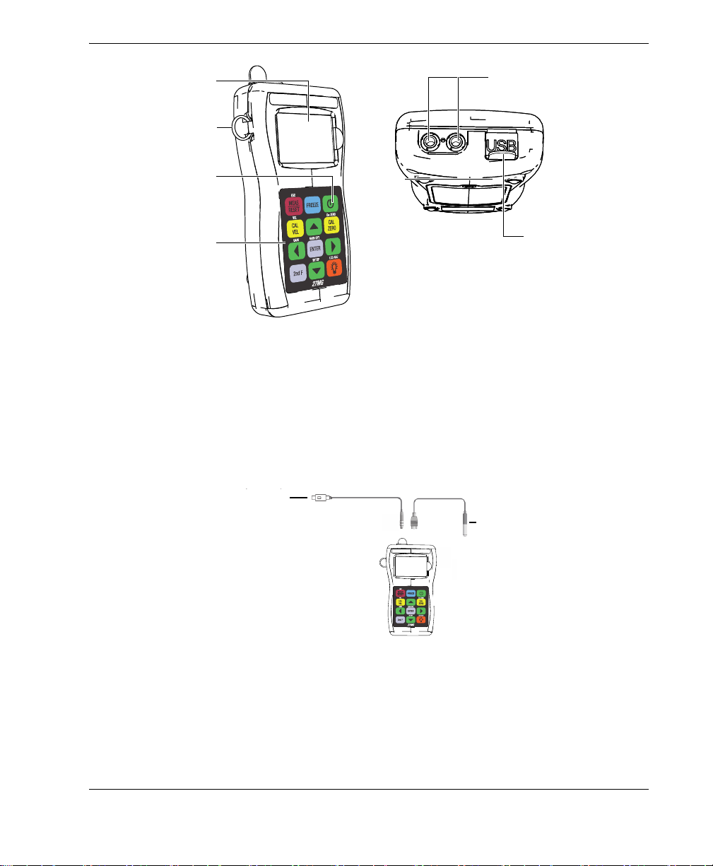
1.3 Instrument Hardware Components
The 27MG front panel features a display and a keypad. The instrument comes with a
wrist strap. An optional protective rubber boot includes strap rings at the four corners
(see Figure 1-1 on page 17).
Chapter 1
16
DMTA-10043-01EN, Rev. C, July 2016
Strap ring
Display
Keypad
Transmit/Receive transducer
connectors
I/O door protecting
USB connector
Power key
Transmit/Receive
transducer
USB connector
(for software upgrades only)
Figure 1‑1 The 27MG hardware components — Front and top views
1.4 Connectors
Figure 1-2 on page 17 illustrates the possible connections between the 27MG and
external devices.
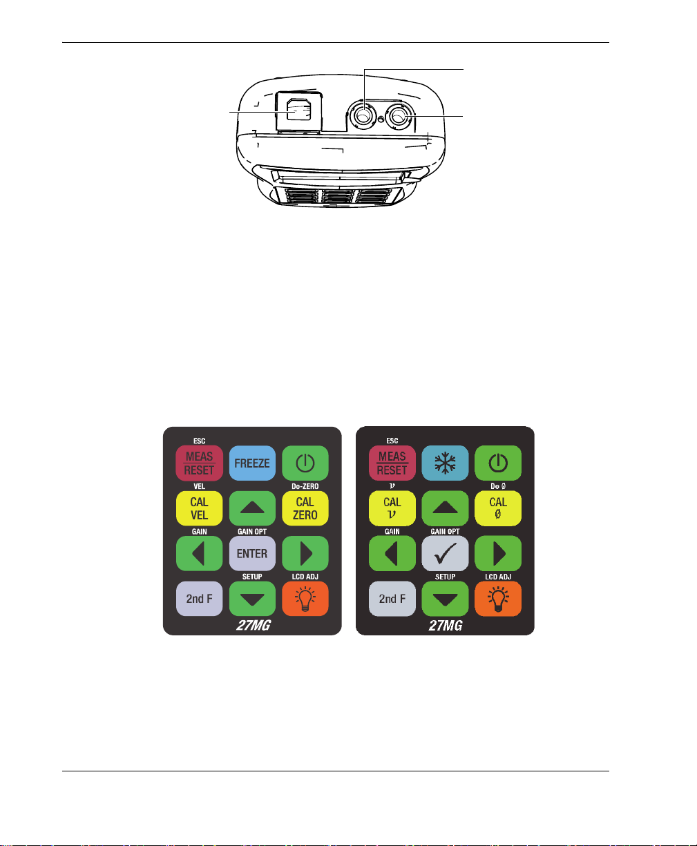
The universal serial bus (USB) and Transmit/Receive transducer connectors are
located on the top of the 27MG (see Figure 1-3 on page 18). The USB connector on the
27MG is only used for upgrading the internal operating software.
Figure 1‑2 The 27MG connections
Instrument Description 17
DMTA-10043-01EN, Rev. C, July 2016
USB communication
connector
Transmit/Receive transducer
connector 2
Transmit/Receive transducer
connector 1
English keypad International keypad
Figure 1‑3 The top end connectors
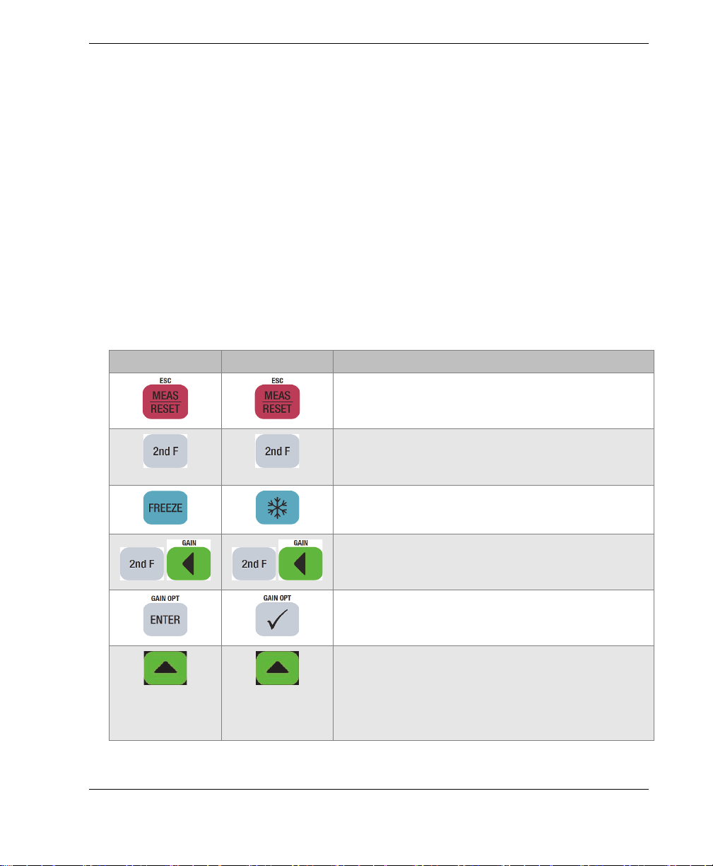
1.5 Keypad Functions
The 27MG comes either with the English or the international keypad (see Figure 1-4
on page 18). The functions are the same for both keypads. On the international
keypad, the text labels on many keys are replaced by pictograms. In this document,
keypad keys are referred to using the English label in bold and within brackets (ex.:
[MEAS]).
Figure 1‑4 The 27MG keypads
Chapter 1
18
DMTA-10043-01EN, Rev. C, July 2016
Each key is labelled according to its primary function. The area immediately above
certain keys contains a secondary key function that can be activated by first pressing
nd
F]. Throughout this document, references to a secondary function are written as
[2
nd
follows: [2
F], [Primary] (Secondary). For example, the instruction to activate the
gain adjust function is written as follows:
Press [2
nd
F], [] (Gain).
The [], [], [], and [] keys, along with the [ENTER] key, are used to select menu
items or display parameters, and to change parameter values. Use the [MEAS] key at
any time to return to the measurement screen. The yellow keys are related to
calibration.
Table 3 on page 19 lists the key functions available on the 27MG keypad.
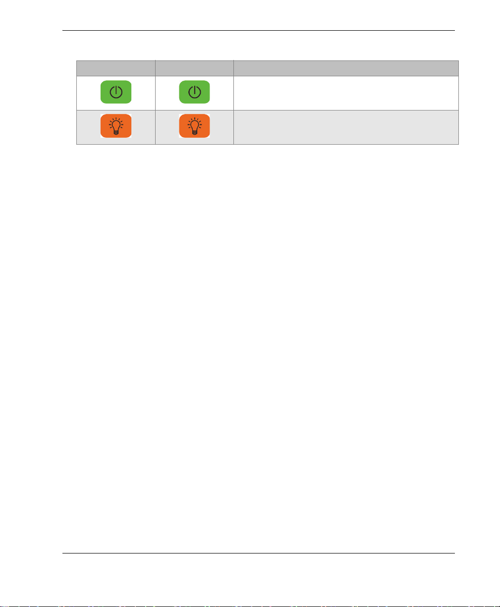
Table 3 Keypad functions
English International Functions
Measurement — Completes the current operation
and returns to the measurement screen.
Secondary function — When pressed prior to
another key, activates the secondary function of
that key.
Freeze — Puts the displayed screen or waveform
on hold until the key is pressed again.
Gain — Initiates the adjustment of the gain value
when using dual element transducers.
Enter — Selects a highlighted item, or accepts an
entered value.
Up arrow
• In a screen or a list, moves to the previous
element.
• For some parameters, increases the value of a
numerical entry.
Instrument Description 19
DMTA-10043-01EN, Rev. C, July 2016
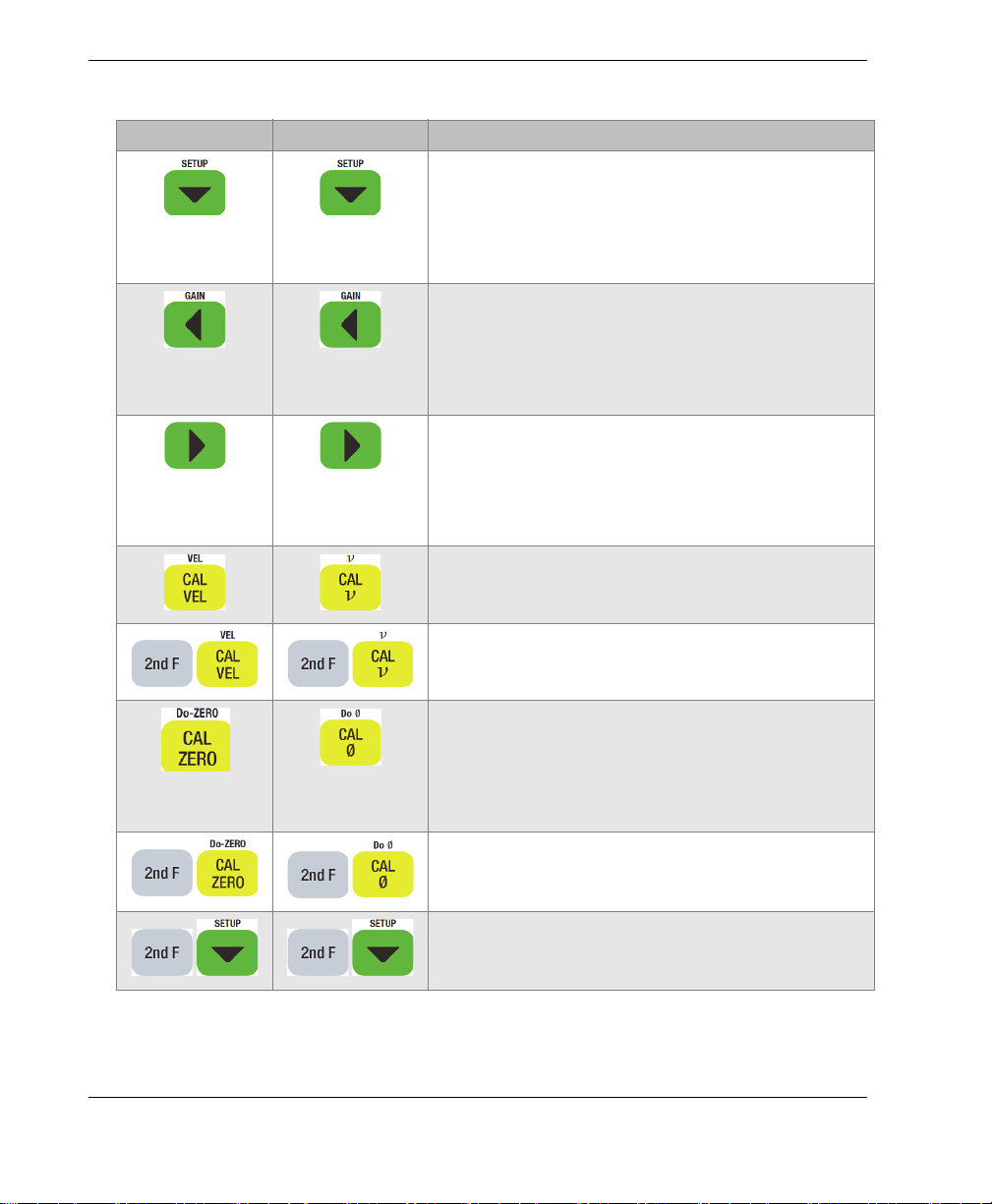
English International Functions
Table 3 Keypad functions (continued)
Down arrow
• In a screen or a list, moves to the next
element.
• For some parameters, decreases the value of a
numerical entry.
Left arrow
• Selects the previous available value for the
selected parameter.
• In text edit mode, moves the cursor one
character position to the left.
Right arrow
• Selects the next available value for the
selected parameter.
• In text edit mode, moves the cursor one
character position to the right.
Velocity calibration — Switches to the
semiautomatic material velocity calibration mode.
20
Velocity — Opens a screen allowing you to view
and manually change the sound velocity.
Zero calibration
• Compensates for transducer zero, or enables
the step block zero calibration.
• With the traditional text edit mode only,
inserts a character at the cursor position.
Do-ZERO — Compensates for transducer delay
for dual element transducers.
Setup menu — Provides access to instrument
parameters (measurement, system, display, alarm,
differential mode, and communication menu).
Chapter 1
DMTA-10043-01EN, Rev. C, July 2016
Table 3 Keypad functions (continued)
English International Functions
Power — Turns the instrument power on or off.
LCD Adjust — Turns on or off the backlight
feature that internally illuminates the LCD screen.
Instrument Description 21

DMTA-10043-01EN, Rev. C, July 2016
22
Chapter 1
 Loading...