

Page 1

Olivetti 3D S2
Printer
SERVICE MANUAL
Code: Y118040-3
Page 2

PUBLICATION ISSUED BY:
Olivetti S.p.A.
Telecom Italy Group
Via Jervis, 77 - 10015 Ivrea (TO)
Italy
Copyright © 2016 Olivetti
All rights reserved
Page 3

Y118040-3 Service Manual iii
PREFACE
This document is intended to be used by technicians responsible for installing and servicing the Olivetti 3D S2 printer.
The aim of the manual is to supply all the information necessary for installing and maintaining the product
correctly.
CONTENTS
This manual comprises of 7 Chapters and an Appendix:
Chapter 1 – Provides a general introduction to the Olivetti 3D S2 printer
Chapter 2 – Provides an illustrated description of the printed circuit boards
Chapter 3 – Provides an illustrated description of installation procedures and printing tests
Chapter 4 – Describes the disassembly/reassembly procedures necessary for printer servicing
Chapter 5 – Provides the planned maintenance procedures
Chapter 6 – Describes the firmware and firmware updating
Chapter 7 – Describes the troubleshooting procedures
Appendix A – Provides a description of the printer accessories
This Manual is completed by a number of video clips, listed below, which can be accessed directly from within
the associated chapters. For this to be possible, the Service Manual and all the video clips must be copied to
the same folder.
Video clip ”Plastic layer bobbin and plastic layer settings”
Video clip “Plastic layer – hot-end group insertion”
Video clip ”Soft glue application method”
Video clip “Nozzle-print plate calibration procedures”
Video clip “Y axis belt replacement”
Video clip ”X axis belt replacement”
Video clip “Print plate calibration”
All the .gcode format files related to the tools and templates referred to in this Manual are available both on the
technical info site www.olinet.biz and on the SD Card supplied with the printer.
PRE-REQUIREMENTS
The approach adopted to the various subjects covered in this manual presumes that the reader has previous
knowledge of similar products.
REFERENCES
Spare Parts Catalogue – code Y117900-2
Product Support Plan – code 808795-00
User Manual German version code 589802
Spanish version code 589701
French version code 589600
Italian version code 589303
English version code 589402
DISTRIBUTION: General
FIRST EDITION: June 2016
Page 4

vi Service Manual Y118040-3
This page is intentionally left blank
Page 5

Y118040-3 Service Manual iii
CONTENTS
PREFACE ..................................................................................................................................................iii
CHAPTER 1 – OVERVIEW .................................................................................................................... 1-1
PRODUCT DESCRIPTION .................................................................................................................... 1-1
MAIN TECHNICAL FEATURES ............................................................................................................. 1-2
TECHNICAL SPECIFICATIONS ............................................................................................................ 1-9
CHAPTER 2 – PCB ASSEMBLY DESCRIPTION ................................................................................. 2-1
DESCRIPTION OF PRINTED CIRCUIT BOARD ASSEMBLIES ........................................................... 2-1
POWER UNIT ......................................................................................................................................... 2-2
ARDUINO PCB ASSEMBLY .................................................................................................................. 2-2
RAMPS PCB ASSEMBLIES ................................................................................................................... 2-3
DISPLAY UNIT ....................................................................................................................................... 2-5
SAFETY SWITCHES ............................................................................................................................. 2--5
CHAPTER 3 – INSTALLATION AND RUNNING THE PRINTING TEST ............................................. 3-1
PACKAGE CONTENTS .......................................................................................................................... 3-1
UNPACKING AND RECOMMENDED OPERATIONS WHEN INSTALLING PRINTER
ON WORK TABLE .................................................................................................................................. 3-3
PRINTER PREPARATION ..................................................................................................................... 3-6
MENUS AND NAVIGATION ................................................................................................................... 3-7
MAIN MENU ....................................................................................................................................... 3-8
PREPARE MENU ............................................................................................................................... 3-9
CONTROL MENU .............................................................................................................................3-11
SD CARD MENU .............................................................................................................................. 3-13
LOADING THE BOBBINS WITH FILAMENTS ..................................................................................... 3-14
PRINTING A TEST PIECE ................................................................................................................... 3-15
CALIBRATING THE EXTRUDER OFFSET ......................................................................................... 3-20
CHAPTER 4 – DISASSEMBLING PARTS AND MAINTENANCE ....................................................... 4-1
TOOL KIT AND TEMPLATES ................................................................................................................ 4-1
REPLACING THE BAKELITE BLOCKS ................................................................................................. 4-3
REPLACING THE NOZZLES ................................................................................................................. 4-7
NOZZLE - PRINT PLATE CALIBRATION PROCEDURE .................................................................... 4-10
CLEANING AND LUBRICATING THE GUIDE RAILS OF THE X AND Y AXES ................................. 4-13
CLEANING THE FOUR COOLING FANS OF THE EXTRUDER BLOCK ........................................... 4-13
VERIFYING AND ADJUSTING THE DRIVER VOLTAGES ................................................................. 4-14
CHECKING THE WIRING OF THE EXTRUDER BLOCK AND HOT-END MOTORS ......................... 4-17
CHECKING THAT HEATING ELEMENTS MAINTAIN OPERATING TEMPERATURE ...................... 4-18
UNMOUNTING THE UPPER BODY AND PANELS ............................................................................ 4-19
Y AXIS BELT REPLACEMENT ............................................................................................................ 4-22
REPLACING THE Y AXIS MOTOR AND IDLE PULLEY ..................................................................... 4-23
X AXIS BELT REPLACEMENT ............................................................................................................ 4-27
REPLACING THE X AXIS MOTOR AND IDLE PULLEY ..................................................................... 4-28
UNMOUNTING THE EXTRUDER BLOCK MOTORS .......................................................................... 4-32
UNMOUNTING THE Z AXIS MOTOR .................................................................................................. 4-36
UNMOUNTING THE PRINTING PLATE .............................................................................................. 4-38
UNMOUNTING THE END-OF-TRAVEL SENSORS ............................................................................ 4-43
UNMOUNTING THE SAFETY MAT ..................................................................................................... 4-44
CLEANING THE HOT-END GROUP ................................................................................................... 4-46
Page 6

vi Service Manual Y118040-3
CHAPTER 5 – PLANNED MAINTENANCE .......................................................................................... 5-1
GENERAL CLEANING ........................................................................................................................... 5-1
PLANNED MAINTENANCE EVERY 6 MONTHS OR EVERY 1000 HOURS OF OPERATION ........... 5-1
PLANNED MAINTENANCE EVERY 2 YEARS OR 4000 HOURS OF OPERATION ............................ 5-1
CHAPTER 6 – FIRMWARE .................................................................................................................... 6-1
UPDATING THE FIRMWARE ................................................................................................................ 6-1
CHAPTER 7 – TROUBLESHOOTING ................................................................................................... 7-1
ERROR MESSAGES .............................................................................................................................. 7-1
TROUBLESHOOTING ............................................................................................................................ 7-1
FAULT CATEGORIES ............................................................................................................................ 7-2
DIAGNOSTIC MESSAGES .................................................................................................................... 7-3
APPENDIX A ACCESSORIES ............................................................................................................ A-1
FILAMENT BOBBIN TYPES ................................................................................................................... A-1
Page 7

Y118040-3 Service Manual 1-1
Chapter 1 – OVERVIEW
PRODUCT DESCRIPTION
The Olivetti 3D S2 printer exploits the Fused Filament Fabrication (FFF) deposition technology to create threedimensional objects by sequentially depositing layers of material in 2-D.
The Olivetti 3D S2 printer is specially designed for small to medium-sized businesses on a digital
transformation path.
In this Chapter the printer components are described and the terminology used in the manual is introduced.
Page 8
1-2 Service Manual Y118040-3
MAIN TECHNICAL FEATURES
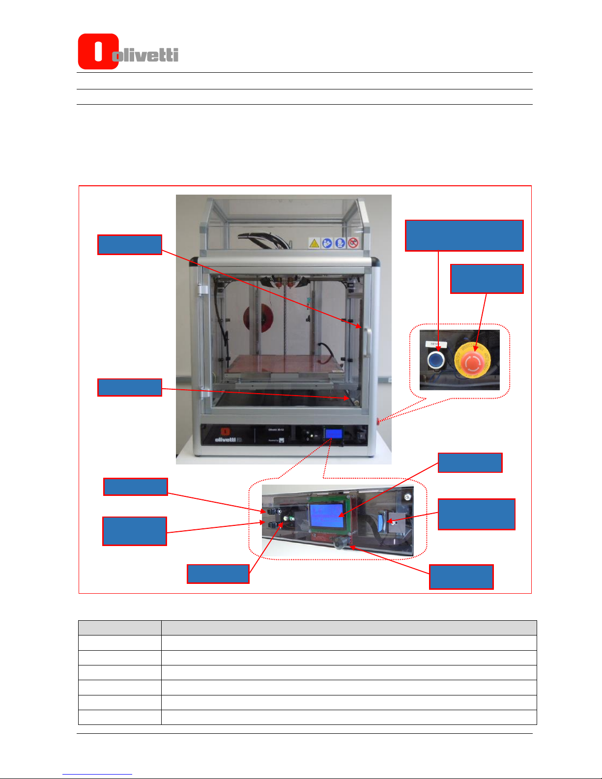
Printer design
The main machine controls are located on the front of the printer where there is also a door for accessing the
inside of the printer.
The safety keys are located on the left side of the printer.
Figure 1-1
REFERENCE
DESCRIPTION
1
LCD Display
2
Jog Dialer
3
SD Card slot
4
Access door
5
Access door lock
6
Switch for fan for cooling material
6-Fan switch
7-Internal light
switch
8 - ON Led
1-LCD
3-SD Card Slot
2-Jog dialer
4-Access door
5-Lock
9-Emergency
stop key
10-Safety mat reset key
Page 9

Y118040-3 Service Manual 1-3
7
Internal light switch
8
Printer power on LED
9
Emergency stop push-button
10
Reset key for safety sensitive mat after activation.
On opening the front door, the hot-end group comprising of extruder 1 and extruder 2 is clearly visible.
Figure 1-2 Hot-end group
REFERENCE
DESCRIPTION
1
Extruder 1
2
Extruder 2
3
Extruder 1 cooling fan
4
Extruder 2 cooling fan
5
Cooling fan for material being printed by Extruder 1
6
Cooling fan for material being printed by Extruder 2
7
Printing plate in tempered glass
4 – Extruder 2
Cooling Fan
2 – Extruder 2
6 – Cooling Fan for
material printed by
Extruder 2
7 – Tempered glass
plate
5 – Cooling Fan for
material printed by
Extruder 1
1 – Extruder 1
3 – Extruder 1
Cooling Fan
Page 10

1-4 Service Manual Y118040-3
Figure 1-3 Hot-end group detail
REFERENCE
DESCRIPTION
1
Nozzle
2
Hot-end
3
Hot-end unlocking setscrew
4
Filament feeder unit
1 - Nozzle
2 – Hot-end
3 – Setscrew di blocco hot-
4 – Gruppo di trascinamento
filament
4 – Filament Feeder Assembly
3 – Hot-end Unlocking Setscrew
Page 11

Y118040-3 Service Manual 1-5
Figure 1-4 Feeder assembly terminals and pressure adjustment screw
REFERENCE
DESCRIPTION
1
Bowden quick release couplings
2
Filament pressure adjustment screw
The bobbins with the filament are installed at the rear of the machine, where there is also the power switch,
power socket and USB port.
1 – Bowden Quick
Release Couplings
2 – Filament Pressure
Adjustment Screws
Page 12

1-6 Service Manual Y118040-3
Figure 1-5 Rear View
Figure 1-6 Rear view detail
REFERENCE
DESCRIPTION
1
Bobbin holders
2
Feeder
3
Power Switch
4
Power Socket
5
USB Port
1-Bobbin Holders
2-Feeder
5-USB Port
3-Power Switch
4-Power Socket
Page 13

Y118040-3 Service Manual 1-7
IMPORTANT: Labels are displayed on some parts of the printer with hazard symbols. The meaning
of these symbols is described in the paragraph “Label positions and meanings”.
Printer axes orientation
The printer moves along three axes: X, Y and Z.
The hot-end group moves in the X and Y axes directions, while the printing plate moves in the Z axis direction.
The origin of the printer axes, known as the extruder Home position, is located at the front left corner of the
printing plate.
Figure 1-7 Orientation of Olivetti 3D S2 printer axes
Starting from the origin, the X axis is oriented from left to right of the work table, the abscissa increasing in this
direction. The positive direction of the Y ordinate axis, starting from the front door, is towards the rear of the
machine, while the positive direction of the Z axis – oriented vertically with respect to the printing plate – is
downwards.
X axis
Z axis
Y axis
Extruder Home Position
Page 14

1-8 Service Manual Y118040-3
Label positions and meanings
On the front top part of the printer the following labels can be seen displayed. The meaning of these symbols is
given in the table below.
Figure 1-8 Labels on front of printer
SYMBOL
COLOUR
WARNING
MEANING
TRIANGLE
YELLOW
DANGER
HOT SURFACES
CIRCLE
BLUE
REGULATIONS APPLY
READ INSTRUCTIONS
CIRCLE
BLUE
REGULATIONS APPLY
USE GLOVES
BARRED CIRCLE
RED
PROHIBITED
DO NOT REMOVE GUARDS
Inside the printer, on the safety sensitive mat, the following labels are displayed. For the meaning of these
symbols see the table below.
Figure 1-9 Internal labels on lower side
SYMBOL
COLOUR
WARNING
MEANING
TRIANGLE
YELLOW
DANGER
CRUSHING
TRIANGLE
YELLOW
DANGER
MOVING PARTS
At the back of the printer, near the on/off switch, the following label is displayed. See the table below for its
meaning.
Figure 1-10 Label on external switch on printer rear
SYMBOL
COLOUR
WARNING
MEANING
TRIANGLE
YELLOW
DANGER
HIGH VOLTAGE
The following label is displayed on the printing plate glass and on the extruder block. For the meaning of this
symbol see the table below.
Figure 1-11 Label on internal heated plate
SYMBOL
COLOUR
WARNING
MEANING
TRIANGLE
YELLOW
DANGER
HOT SURFACE
Page 15

Y118040-3 Service Manual 1-9
TECHNICAL SPECIFICATIONS
Case: Radiused anodised aluminium 45 x 45 with methacrylate panels
Power supply: input 100-240V 50-60 Hz 125-250V / 2.8A
output 12V 8.34A 100W
Display: Front LCD 128 x 64 dot matrix.
Printing plate: 5 mm tempered glass, heated. Maximum temperature 120°C.
Extruders: 2 extruders. Maximum temperature 280°C.
Filament: ø 1.75 mm
Print mode: Cartesian, horizontal dimension along X and Y axes,
Vertical, vertical dimension along Z axis.
Maximum printing speed: 150 mm/sec.
Min layer thickness: 0.05 mm (50 micron).
Min. thicknesses with different nozzles:
Nozzle diameter 0.30 mm min. layer thickness 0.05 mm recommended layer thickness 0.10
mm
Nozzle diameter 0.40 mm min. layer thickness 0.10 mm recommended layer thickness 0.20
mm
Nozzle diameter 0.80 mm min. layer thickness 0.20 mm recommended layer thickness 0.40
mm
N.B.: Nozzles with a diameter of 0.50 mm are mounted on the machine, while nozzles of diameters 0.30,
0.4, 0.50, 0.60 and 0.80 mm can be purchased separately.
Precision tolerance: 0.08 mm (80 microns) on X/Y axes.
0.01 mm (10 microns) on Z axis.
Max. printing volume: 400x400x400 mm
Firmware: Marlin Open source.
Machine code: Movement and printing operations are executed by GCODE machine
code.
Software: Compatible with the most popular printing software that supports
Marlin firmware such as: Repetier-Host, Simpllify3D, Cura, Slic3r, Kisslicer, for
generating GCODE machine code.
Safety devices: Emergency stop key.
Safety mat on bottom floor of printer.
Safety mat reset key.
Page 16

1-10 Service Manual Y118040-3
This page is intentionally left blank
Page 17
Y118040-3 Service Manual 2-1
Chapter 2 – PCB ASSEMBLY DESCRIPTION
DESCRIPTION OF PRINTED CIRCUIT BOARD ASSEMBLIES
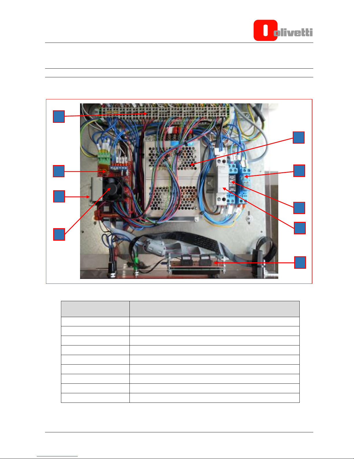
The figure below shows the metal plate with the electronic components of the printer:
Figure 2-1
REFERENCE
DESCRIPTION
A
Input/output wire terminals
B
RAMPS Card
C
Arduino MEGA 2560 Card (positioned under the RAMPS card)
D
Cooling fan for RAMPS card
E
SD Card connector and display card
F
Fuse holder
G
Emergency stop key relay
H
Safety mat relay
I
Power unit
I G A B C F H E D
Page 18
2-2 Service Manual Y118040-3
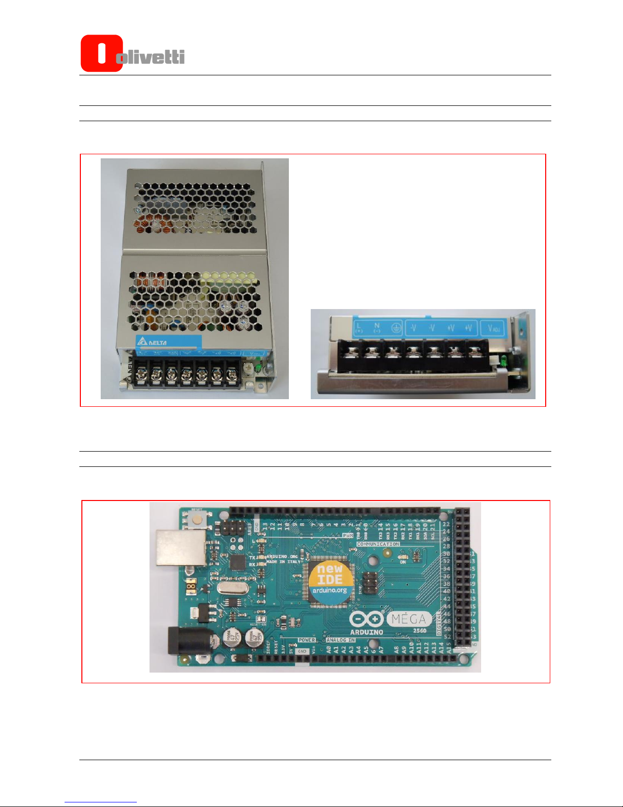
POWER UNIT
The figure below shows the power unit and the terminal board for the wire connections.
Figure 2-2
ARDUINO PCB ASSEMBLY
The illustration below shows the A side of the Arduino card.
Figure 2-3
Page 19
Y118040-3 Service Manual 2-3
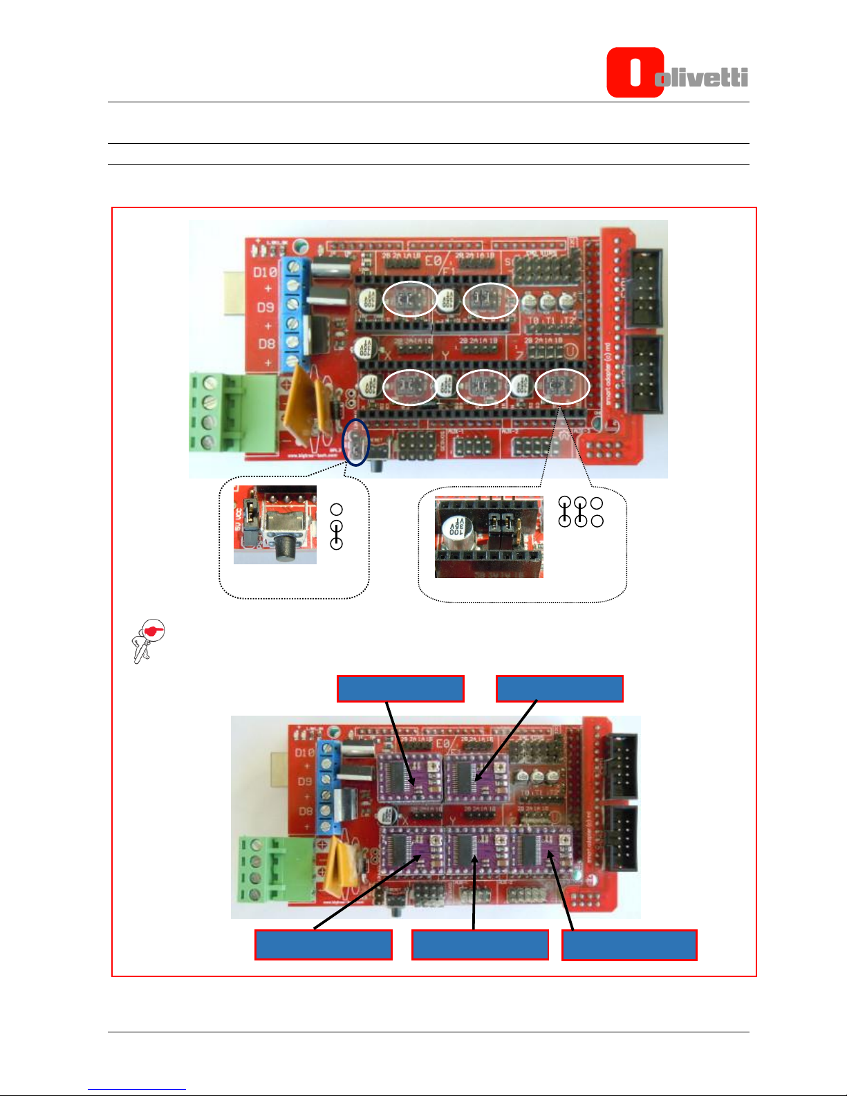
RAMPS PCB ASSEMBLIES
In the illustrations below can be seen the A side of the RAMPS card and its related block diagram.
NOTE: The two enlarged views show the jumpers located under the five driver chips
(circled in white) - all of which must have the same setting - and the power selection jumper
(circled in dark blue).
Figure 2-4
Extruder 1 Driver
Extruder 2 Driver
Y Axis Motor Driver
X Axis Motor Driver
Z Axis Motor Driver
Power selection
jumper
Jumpers under driver IC
Page 20

2-4 Service Manual Y118040-3
The figure below shows one of the five Driver chips mounted on the RAMPS card.
Figure 2-5
Figure 2-6
Page 21
Y118040-3 Service Manual 2-5
DISPLAY UNIT
The figure below shows the display unit comprised of the jog dialer and the connector for the SD Card device
mounted on the printer side.
Figure 2-7
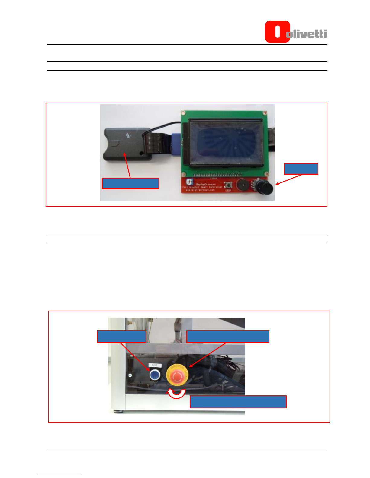
SAFETY SWITCHES
The printer is equipped with two safety switches.
1. The Emergency Stop key – this key can be activated whenever a dangerous situation arises.
After the Emergency Stop key is activated it must be reset by rotating it in the direction indicated by the
arrows.
2. The Reset key – this key must be pressed after a machine shutdown caused by abnormal pressure being
applied to the safety mat which blocks printer operation.
Figure 2-8
SD Card connector
Jog dialer
Emergency Stop key
Reset key
Direction to turn key for reset
Page 22

2-6 Service Manual Y118040-3
This page is intentionally left blank
Page 23

Y118040-3 Service Manual 3-1
Chapter 3 – INSTALLATION AND PRINT TEST
PACKAGE CONTENTS
The following items are contained in the Olivetti 3D S2 printer package:
- 1 3D S2 Printer
- 1 Printer Door Key
- 1 USB Cable. Type A-B
- 1 AC Power Cord
- 1 SD Card of 4GB or more
- 3 Allen Keys (1.5 mm, 2.5 mm and 5 mm)
- 3 Hex Wrenches, sizes 8, 10 and 12
- 1 PLA Bobbin, diameter 1.75 mm, weight 1 Kg
- 1 Feeler Gauge, 0.08 mm
- 1 Spatula for removing printed pieces
- 1 EC, WEEE and Safety Declarations Leaflet
General instructions for installation
To guarantee top printer operation and avoid the need for servicing operations - other than those necessary as
a result of product defects - adhere to the following instructions:
Electrical Power
Make sure that the socket to which the printer is connected is earthed and that it supplies the power level
required by the printer.
WARNING: an unearthed socket may cause faulty operation and create safety-related issues.
Do not connect the printer to power supply lines used in common with other types of apparatus that could
create electrical disturbances and excessive voltage variations (air conditioning systems and fans,
photocopiers, motors of goods lifts or person lifts, radio and TV transmitters and signal generators, high
frequency security devices, etc.).
Environmental conditions
The environmental conditions under which the product can be kept for an unlimited period of time are those
indicated by the AB quality objectives for a normal, air-conditioned, office environment (ambient temperature
15-35 °C, relative humidity 35-85% HU). During both storage and operation, it is necessary to prevent
variations in environmental conditions which could give rise to condensation phenomena. Dust, dirt, smoke
and excessive humidity can lead to excessive wear of moving parts, short circuits and read/write errors while
the printer is executing the different operations. High temperatures and low humidity levels can lead to static
electricity problems.
Printer location
The printer must be installed on a flat, vibration-free, surface.
Do not position the printer very close to air ventilation systems or heat sources, or in positions where it will be
exposed to direct sunshine. Install the printer in a position that is convenient and easy to reach for servicing
and removal operations.
Page 24

3-2 Service Manual Y118040-3
Operator Information
At the end of the installation, the Field Engineer must ensure that the Operator is in possession of all the
information necessary for operating the printer correctly, and is capable of carrying out the operations for
replacing the bobbin and printing nozzles, and for clearing clogging caused by the filament.
For this purpose, it is recommended that you provide a practical demonstration on how to perform the following
operations:
- Use of the console. Interpretation of error messages and, where possible, operations for removing a printer
jam.
- Illustration of methods for inserting and managing filaments.
- Bobbin replacement.
- Removal of filament clogging printer.
- Printing nozzle replacement.
- Printing of test file.
- Manual printer cleaning.
Make the Operator aware of the importance of environmental conditions when choosing the location for
installing and operating the printer.
Remember that the printer will function reliably over time if used correctly. In the case of any faults, contact
Technical Support immediately.
Page 25

Y118040-3 Service Manual 3-3
UNPACKING AND RECOMMENDED OPERATIONS FOR PRINTER INSTALLATION ON WORK TABLE
1. With the printer resting on the ground (Figure 3-1) remove the top outer cover (Figure 3-2).
Figure 3-1 Figure 3-2
2. Remove the two pieces of protective padding (Figure 3-3) lifting them out (Figure 3-4).
Figure 3-3 Figure 3-4
Page 26

3-4 Service Manual Y118040-3
3. Remove the external cardboard packaging by lifting it upwards (Figure 3-5).
On the left side of the printer there are two boxes containing the printer accessories (Figure 3-6).
Figure 3-5 Figure 3-6
4. For the best, most ergonomic, use of the printer, choose a surface with a good level of staticity and
meeting the following specifications:
Work table height: ≥ 80 cm
Work table area: 100 cm x 100 cm
load resistance: ≥ 150 Kg
5. To place the printer on the work table, use a forklift truck of sufficient capacity to lift the printer up to the
height of the work table surface.
Page 27

Y118040-3 Service Manual 3-5
It is recommended that two persons carry out this operation, proceeding as follows:
6. Unpack the printer, load it onto the forklift truck and lift it up to the height of the work table.
Figure 3-7
7. Lift the printer to the height of the work table (arrow 1) and manually rest it on the surface (arrow 2).
NOTE: The printer bottom must rest entirely on the surface
Figure 3-8
8. Move the forklift truck away.
Figure 3-9
1
2
Page 28
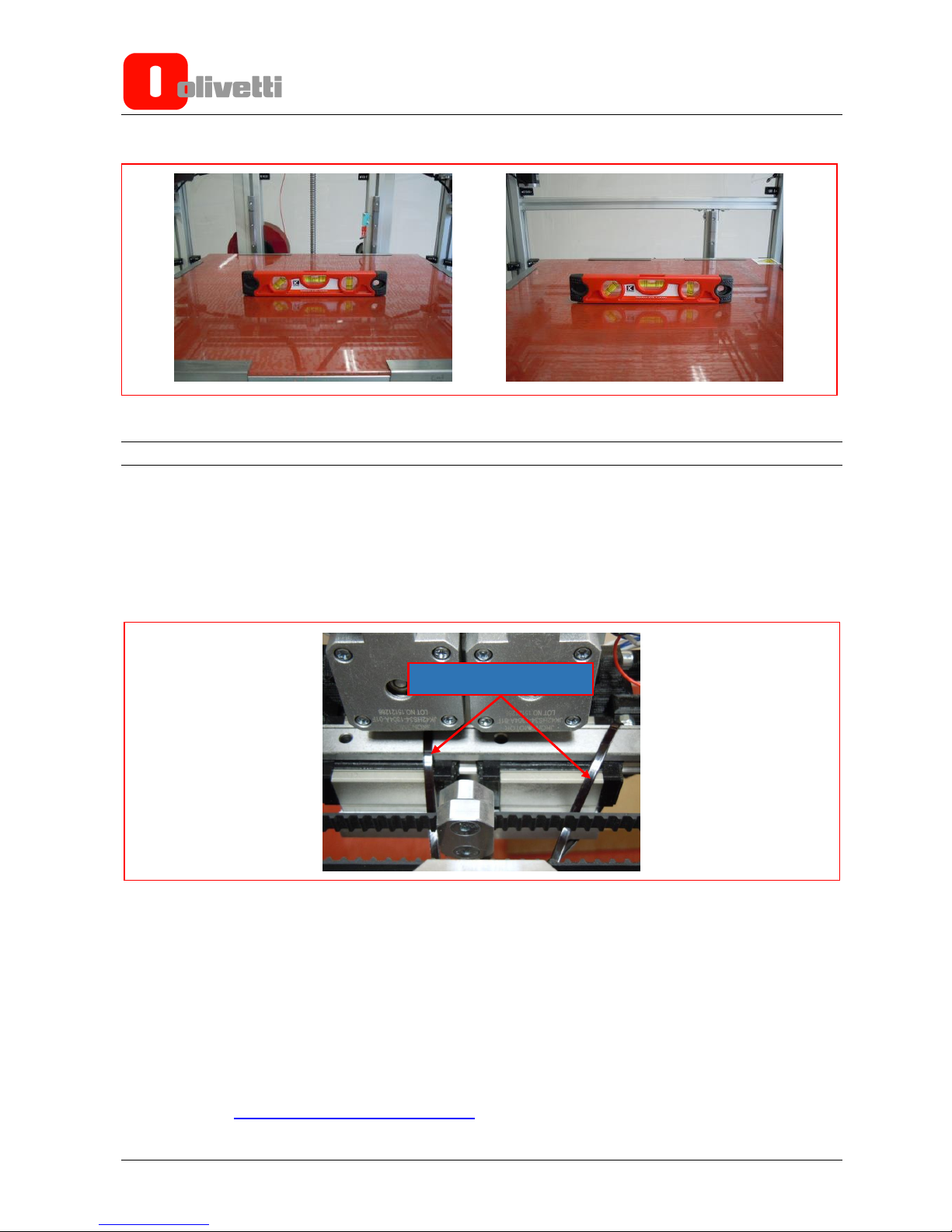
3-6 Service Manual Y118040-3
9. With a spirit level, ensure that the printer is level in the X axis (Figure 3-10) and Y axis (Figure 3-11) directions.
Figure 3-10 Figure 3-11
PRINTER PREPARATION
This Chapter describes the procedures necessary for correctly configuring and preparing the Olivetti
3D-S2 printer for printing.
Unblocking the hot-end group
To protect the printer during shipping, the hot-end group is anchored to the centre of the Z axis (at the machine
rear) using two packing straps. Before attempting to use the printer you must therefore unblock the hot-end
group by removing these straps.
Figure 3-12
Powering on the printer
Connect the printer to a 220V electrical outlet using the power cord provided and power it on at the power switch.
LCD Display
When the printer is powered on, the LCD display illuminates.
On the display is shown the most important printer status information.
Loading the filament bobbins
See the Chapter ”Loading the Bobbins with Filaments”.
Cut packing straps
Page 29

Y118040-3 Service Manual 3-7
MENUS AND NAVIGATION
The User Interface of the Olivetti 3D S2 printer provides the commands for carrying out the calibration,
maintenance and printing operations. On powering on the printer, an initialisation screen is displayed for a few
seconds giving the firmware release version, date and time.
Figure 3-13 Initialisation page
This is followed by an information page with the following details:
Target temperature setting for extruders and printing plate (A).
Actual temperature of extruders and printing plate (B).
Position of extruders with respect to the three axes X, Y and Z (C).
Printing speed (D).
Information on insertion of SD Card (E).
Tool bar indicating percentage of work performed (F).
Time since printing began (G).
Figure 3-14 Start page
Figure 3-15 Jog dialer
To navigate between the menus, turn the jog dialer either in the clockwise or anti-clockwise direction.
To select a given command or menu, press the jog dialer.
A B C D G F E
Page 30

3-8 Service Manual Y118040-3
MAIN MENU
To access the main menu, press the jog dialer once when the printer is in rest mode with the Start page
displayed.
Figure 3-16 Main menu
From the Main menu you can return to the Start page by moving to the Info screen option using the jog dialer
and then pressing the jog dialer to confirm.
In any case, if the printer remains inactive for about 20 seconds, it returns automatically to the Start page.
From the main menu you can access the following submenus:
Prepare
Control
Print from SD
Page 31

Y118040-3 Service Manual 3-9
PREPARE MENU
From the Prepare menu you can carry out the principal machine calibrations. From this menu the following
submenus can be accessed:
Figure 3-17 Prepare menu submenus
Auto Home
Bed Setting
Move axis
Disable Steppers
Auto Home:
Positioning on the Auto Home command using the jog dialer and pressing to confirm, the printer moves the
extruders and the printing plate to the rest position (positioning the extruders at the front left corner of the
printing plate).
Bed Setting:
This command can be used to modify the distance of the nozzles from the printing plate. When this command
is given, the extruders are positioned at the four corners of the printing plate, approximately 20 cm from the
vertices. As the final position, the extruders are positioned at the centre of the plate.
Move axis:
This command can be used to move the printer axes.
Two types of movement are possible: rapid (10 mm) and slow (1 mm).
Figure 3-18 Axis setting commands
Page 32

3-10 Service Manual Y118040-3
Selecting the Move 10 mm submenu allows you to move the printhead rapidly along the X and Y axes (the
example in the figures below shows how to move 160 mm in the positive direction along the x axis).
Figure 3-19 Rapid settings menu
Selecting the Move 1 mm submenu, you can move both the X and Y axes and the Z axis (printing plate) as
well as the motors for feeding the filaments of Extruder 1 and Extruder 2 (N.B. to move the filaments, set the
Extruder temperature to the melting point of the material used).
Figure 3-20 Intermediate settings menu
Disable steppers:
If you need to move the X and Y axes manually, use this command to disable the motors controlling the
movement of these axes. To disable the motors, move to Disable steppers and press the jog dialer. The
motors are enabled again on receiving the first command from the printer,.
Figure 3-21 Disable steppers
WARNING: move the hot-end group slowly and carefully along the X and Y axes to avoid
inadvertently generating surplus currents which could cause damage to the electronic components.
Page 33

Y118040-3 Service Manual 3-11
CONTROL MENU
The Control menu gives you access to all printer parameter settings, allowing you to modify each one singly
as you need. From this menu you can access the following submenus:
Figure 3-22 Control menu and related submenus
Temperature
Motion
Restore failsafe
Temperature:
Accessing the Temperature menu you can adjust the temperature of Nozzle 1.
To do this, use the jog dialer to move to the Nozzle command then confirm by pressing the dialer.
Rotate the jog dialer to set the temperature to the desired level then press to confirm; in this way the machine
will heat the nozzle to the temperature value set.
Similarly, by selecting Nozzle 2, you can set the temperature for the second nozzle.
Figure 3-23
To set the temperature of the printing plate, select Bed then rotate the jog dialer to the required value.
Figure 3-24
Page 34

3-12 Service Manual Y118040-3
Selecting Fan speed you can vary the rotating speed of the two fans mounted on each of the two extruders.
Figure 3-25
Motion:
When you select this command, the acceleration speed of the motors of the X and Y axes is displayed.
NOTE: currently there is no need to modify this parameter.
Selecting Endstop abort you can enable or disable interruption of printing when an abnormal position is
assumed at end-of-travel (either by the extruder heads or the printing plate).
Figure 3-26
Page 35

Y118040-3 Service Manual 3-13
By selecting Restore failsafe and confirming, you can reload the default parameter values set in the factory.
Figure 3-27
SD CARD MENU
Selecting Print from SD using the jog dialer and confirming, you can display the contents of the SD Card
inserted, navigate between the files saved on it, select and print a file.
Figure 3-28
Page 36

3-14 Service Manual Y118040-3
LOADING THE BOBBINS WITH FILAMENTS
1. Position the bobbin on its holder and insert the filament inside the feeder as shown in the video clip ”Plastic
layer bobbin and plastic layer settings”.
2. Regulate the temperature of the hot-end to the appropriate operating value for the type of filament loaded
(for example, 200°C for PLA), proceeding as described below:
Switch on the printer by setting the power switch to the ON position. The Menu Start page is shown on
the display.
NOTE: you can navigate between the menus by turning the jog dialer in either the clockwise or anticlockwise direction. To select a given command or menu press once on the jog dialer.
Select the Control menu.
Position on the Temperature menu and select it.
To modify the temperature of Extruder 1 select Nozzle, to modify the temperature of Extruder 2 select
Nozzle 2.
Rotate the jog dialer to set the required temperature value depending on the type of filament installed
(refer to the “OPERATING TEMPERATURE” table).
Press the jog dialer repeatedly to confirm and return to the Start page where the temperature value
setting and actual nozzle temperature are both displayed.
Wait the time necessary for the nozzle to reach the temperature value set.
Figure 3-29 Command sequence for setting the temperature
Insert the filament inside the feeder unit as shown in the video clip “Plastic layer-hot end group insertion” .
Page 37

Y118040-3 Service Manual 3-15
WARNING: on the first manual extrusion you may find residues of previously printed material; this is
completely normal because the machine is subjected to testing before being packaged.
NOTE: should the filament not flow out smoothly, repeat the previous steps because either the
operating temperature is incorrect for the type of filament loaded or a duct must still be obstructed with
Teflon tape.
PRINTING A TEST PIECE
On the SD Card supplied in the package there is a file that can be used for running a printing test, so that you
can gain confidence using the printer.
To ensure good bonding between the first layer printed and the printing plate, spray a thin adhesive solution
on the plate, as shown in the video clip ”Soft glue application method” . To print the test piece proceed as
described below:
1. Insert the SD Card supplied in the package into the slot at the front of the printer.
Select Print from SD to access the file manager.
Select the file to print (for example: Test cube.gcode) by rotating the jog dialer and pressing to
confirm.
Figure 3-30 Command sequence for printing a piece
2. Launch printing. The printer carries out the following procedures:
Homing of all axes.
Heating of hot-end and plate (if necessary) until the temperature required is reached.
Extrusion of a length of material for loading into the extrusion chamber.
Movement in the printing area and start of printing procedure for each successive layer.
On terminating printing, the machine executes the Homing procedure for the carriage and switches off
the heaters to allow the extruders to return to ambient temperature.
All printing processes can be monitored from the printer display’s Start screen.
NOTE: The printing format supported by the Olivetti 3D S2 printer has the extension .gcode.
Page 38

3-16 Service Manual Y118040-3
Creating a printable file using the Olivetti 3D S2 printer
The steps necessary for producing your own printable .gcode files using the Olivetti 3D S2 printer are
described in this paragraph.
Creating a 3D model
The first step is to create a three-dimensional model of the object you want to print.
To create the model, you can either use a commercially-available 3D CAD design software or free software,
such as, OpenSCAD, Blender, SketchUp and FreeCAD.
Alternatively, you can also download ready-to-use 3D models available for free on internet sites, such as
Thingiverse and GrabCAD.
3D models come in different file formats however you are advised to generate or download models in .STL
format (STereoLithography), this being the most commonly used and easily managed by the programs that
will be used subsequently for generating the .gcode file for printing in 3D.
Creating a GCODE from a 3D model
Once the 3D model in STL format is ready, it must be further processed to transform it into GCODE so that it
is printable. The transformation from a 3D model to gcode is achieved using dedicated software applications
known as Slicers. These programs subdivide the 3D model into sections that the 3D printer can deposit on the
printing table.
Many different types of slicer exist, among which we particularly recommend Slic3r and Cura or the Repetier
Host environment. The latter - apart from having its own slicing software - also provides useful tools for
redimensioning, copying and repositioning the model on the printing plate.
Figure 3-31 3D model during conversion phase of Repetier Host
After having generated the GCODE file using the slicer, copy it onto the SD card that will be used for printing
after insertion into the Olivetti 3D S2 printer.
Page 39

Y118040-3 Service Manual 3-17
GCODE Printing
Now to print your GCODE, proceed as explained in the paragraph ”PRINTING A TEST PIECE”.
Overhang and generation of support material
Overhang is the term used to describe those portions of model that cannot be printed using the FFF printing
process without the help of suitable support underneath.
The FFF technology, in fact, assumes that layers will be deposited successively, one on top of the other. The
presumption is therefore that every layer has a supporting layer underneath.
If your 3D model has planes or surfaces that rise upwards from the bottom with a tilt in excess of about 50°
with respect to the vertical plane (40° from the surface), the layer deposited may not have a suitable support
surface underneath, and may therefore cede compromising the quality of the printed work piece.
To avoid problems related to overhang, the slicing software automatically generates material supports
whenever necessary (based on user-configurable parameters).
This additional material must therefore be removed manually after printing is terminated.
Suspending and interrupting printing
Using the menu you can suspend or cancel printing after it has been launched.
To suspend printing, press the jog dialer and enter the menu. Rotate the dialer to the Pause print command
then press to confirm.
Printing will be suspended and on the menu Start page the Pause print status is displayed.
Figure 3-32 Command sequence for suspending printing of a piece
Page 40

3-18 Service Manual Y118040-3
To restart printing just press the jog dialer.
Figure 3-33 Restarting printing
NOTE: when printing is suspended, the high nozzle temperature may result in material continuing to
flow, resulting in distortions in the piece printed.
To cancel printing, access the menu and move to Stop Print using the jog dialer, then confirm by pressing the
jog dialer. Printing is cancelled.
Figure 3-34 Stop print
Note that the hot-end group will remain frozen at the last position assumed before printing was cancelled. To
return it to its Home position you can either move it manually using the menu commands or execute a Homing
procedure.
Page 41

Y118040-3 Service Manual 3-19
Removing printed pieces
You may find that the printed piece is very strongly bonded to the glass printing plate. This is due to use of
the bonding solution to create good adhesion of the first layer to the plate, creating a "vacuum" effect which
literally glues the piece to the glass.
WARNING: Exercise the greatest care when removing printed pieces from the glass using sharp or
pointed objects. In fact you are strongly advised not to use either knives or cutters for removing
pieces from the glass, even of small dimensions. Although the glass is tempered it is also fragile,
therefore use the utmost care when touching and handling it.
Remove the printed piece from the glass only after having waited the time necessary for it to cool
(when the heated surface has been used). Always check the temperature on the display before
accessing the printing area because some parts may still be very hot, even after printing has
finished.
Never apply force to lever off the printing plate glass.
Do not apply excessive or direct force to the piece using heavy objects such as hammers etc.
The simplest way to detach a piece is to leave it to cool on the printing plate until 35°C; as plastic and glass
have different dilatation coefficients, the tensions created during cooling are conducive to detaching the
bottom layer of plastic from the plate.
Using the spatula supplied with the printer to help you, insert its metal edge under the border of the work
piece and twist slightly. This will cause the piece to come free. Another trick for removing small pieces is to
tap them with the handle of the spatula at a chosen point and taking care not to damage them. Do not use
excessive force, light tapping should cause the bottom to come free from the glass. The spatula is very
useful for removing any pre-printing flushing residues, known as “skirt”.
Page 42

3-20 Service Manual Y118040-3
CALIBRATING THE EXTRUDER OFFSETS
To be able to print with the dual extruder you must calibrate the offsets of the two printheads.
Before proceeding with the offset calibration, adjust the nozzle height as described in the Chapter NOZZLE
PRINT PLATE CALIBRATION PROCEDURE and REPLACING THE NOZZLES”.
The two hot-ends are kept in position by a block of aluminium. Their nominal alignment should be, on the
horizontal surface, X = 55 and Y = 0. However it is possible, due to small tolerances of the parts, that the
two heads are not aligned at this value. In this case it is necessary to carry out a calibration operation using
a test piece to allow any appropriate offset values to be set in the slicing software.
You are advised to carry out this operation whenever the heads are adjusted, changed, etc., or when
operations are carried out on the bakelites or on the nozzles.
The part to print for offset calibration is located in the following subfolder of the SD Card:
\GCODE\CALIBRATION\DUAL_HEAD\calibration_test.gcode
If the horizontal and vertical lines in each of the two colours are not aligned, you must “compensate” for the
excess in the X and Y elements by measuring the piece printed on the plate, as follows:
Figure 3-35
The misalignments measured on the printed piece, as shown in the illustration, allow you to set the
compensation for the slicer offset parameter as follows:
ΔX+ Insert the X axis offset obtained from the measurement as a positive value
ΔX- Insert the X axis offset obtained from the measurement as a negative value
ΔY+ Insert the Y axis offset obtained from the measurement as a positive value
ΔY- Insert the Y axis offset obtained from the measurement as a negative value
Horizontal
Alignment
[Y]
Horizontal
Alignment
[X]
Page 43

Y118040-3 Service Manual 4-1
Chapter 4 – DISASSEMBLING PARTS AND MAINTENANCE
To ensure maximum safety conditions and a successful outcome of operations, observe the following
instructions:
- For all disassembly and reassembly operations, switch off and disconnect the printer from the mains power supply.
- Carry out all operations in areas that are clean and free from obstacles.
- Follow procedures scrupulously; do not unscrew parts that must not be disassembled. Conserve parts in a
clean place, where they will not get lost.
- After replacing parts, check that they have not been deformed during assembly; if necessary correct.
- Operations for reassembling parts, unless otherwise indicated, must be carried out using the reverse
sequence of operations to that used for disassembly.
- Ensure that all connectors are connected correctly. After interventions, relubricate as indicated in the
specifications.
- At the end of operations, perform a test to check that the printer functions correctly without any problems.
TOOL KIT AND TEMPLATES
Certain technical interventions on the printer require mechanical adjustments to be carried out.
To allow these adjustments to be carried out correctly, a tool kit and templates are provided, which must form
part of the equipment used by the Technician when operating on the machine.
The following images show the kit composition together with a description of how each tool and template must be
used:
Kit for adjusting the tension of the X and Y axes belts.
Figure 4-1
REFERENCE
TOOL USE
1
HOOK * FOR ADJUSTING THE TENSION OF THE X AND Y AXES BELTS
2
BRACKET FOR ADJUSTING THE TENSION OF THE X AXIS BELT
3
BRACKET FOR ADJUSTING THE TENSION OF THE Y AXES BELT
* To adjust the tension, a downward force of 1300 g must be applied to the hook. This is possible by simply
tying an appropriate weight to the hook strap.
2
1
3
Page 44

4-2 Service Manual Y118040-3
Kit for adjusting the pulley heights and the position of the Y axis motor.
Figure 4-2
REFERENCE
TOOL USE
1
TEMPLATE FOR ADJUSTING THE HEIGHT OF THE IDLE PULLEY OF THE Y AXIS
2
SHIM (2.9 mm) FOR ADJUSTING THE DISTANCE OF Y AXIS MOTORS
3
SHIM (1.5 mm) FOR ADJUSTING THE HEIGHT OF THE X AXIS PULLEYS
4
TEMPLATE FOR ADJUSTING THE HEIGHT OF THE Z AXIS MOTOR PULLEY
All files in .gcode format for the parts composing the kit are provided on the SD Card supplied with the product.
This allows you to create these tools and templates autonomously, using the Olivetti 3D S2 printer .
1
4 3 2
Page 45

Y118040-3 Service Manual 4-3
REPLACING THE BAKELITE BLOCKS
Preventive and maintenance inspections are advised every 6 months or every 1000 hours of operation. The
photo below shows the two hot-ends of the extruder block with the cooling fans rotated upwards.
Figure 4-3
1. In most cases, the block arrives with the filament already inserted inside. To remove it and proceed with
operations, you must heat the extruder as described in the paragraph “Setting the temperature of the hot-
end”.
Bring the extruder to the temperature necessary for the type of filament installed, referring to the filament
temperature table.
When the temperature is reached, enter the Prepare menu
Position on and select the Move Axis menu.
Enter the menu Move 1 mm and select the nozzle desired (in this example Extruder 1).
Now turn the control knob anti-clockwise so that 3 or 4 cm of filament extrudes, then immediately turn
the knob clockwise 9 or 10 cm.
NOTE: the filament can also be inserted into the hot-end by turning the knob in this manner, using the
same sequence.
Bakelite Blocks
Hot-ends
Nozzles
Hot-end Setscrew
Page 46

4-4 Service Manual Y118040-3
Figure 4-4 Command sequence for inserting/extracting the filament from the extruder
3. The internal software saves your work in memory, the printer then extrudes and retracts the filament,
according to an automatic sequence, so that you will find the filament extruding out of the thrust gear
block.
4. Once the filament is extruded from the hot extruder, lower the temperature to 140°C as described in the
paragraph “Setting the temperature of the hot-end”.
WARNING: for the operations described below you are advised to wear heat-resistant gloves as a
protection from burns that could be caused by the operating temperature of the extruder block.
5. Using a 2.5 mm Allen key, unscrew the setscrew of the hot-end group to be unmounted.
Figure 4-5
Hot-end 1 Setscrew
Hot-end 2 Setscrew
Page 47

Y118040-3 Service Manual 4-5
6. Extract the hot-end group from its conduit.
Figure 4-6
7. With the hot-end group released, use the 12 mm hex wrench to unscrew the bakelite block.
NOTE: To make this operation easier, the wrench supplied with the printer has a low profile.
Figure 4-7
8. Before mounting the new bakelite block, you are advised to pass a metal wire of diameter 1.2 mm through
the hole in the Teflon lining to remove any impurities (for this operation a drill bit also can be used).
12 mm Hex Wrench
12 mm Hex Wrench
Page 48

4-6 Service Manual Y118040-3
Figure 4-8
9. Still with the hot-end hot, take the new block of bakelite and wind Teflon tape 4 times around the thread,
being careful not obstruct the hole. Now manually screw the bakelite back onto the hot-end block until the
end, then give it a further half-turn with the 12 mm hex wrench to tighten the group perfectly.
Figure 4-9
10. Put the whole hot-end group back into position in its conduit, pushing it in up against the thrust gear.
Figure 4-10
Thrust Gear
Page 49

Y118040-3 Service Manual 4-7
11. Screw the setscrew on again, tightening moderately, to fasten the hot-end group.
12. Move the cooling fan back to its operating position.
13. Adjust the nozzle–printing plate distance as described in the next Chapter NOZZLE PRINT PLATE
CALIBRATION PROCEDURE” and ”REPLACING THE NOZZLES”.
When two extruders are used, you are advised to check the offset setting, as described in the Chapter
”CALIBRATING THE EXTRUDER OFF-SETS”.
14. Bring the hot-end to the working temperature as described in the paragraph “Setting the temperature of the
hot-end”.
15. Insert the filament into the hot-end from the menus as described in Figure 4-4 Command sequence for
inserting/extracting the filament from the extruder.
REPLACING THE NOZZLES
To avoid the hot-end block getting jammed due to the use of different mixtures, you are advised to replace the
nozzle every time you change the type of material used as the filament, or whenever a jam occurs.
WARNING: for the operations described in the video clip, you are advised to use heat-resistant
gloves to avoid burns caused by the operating temperature of the extruder block.
1. As described in Figure 3-29 Command sequence for setting the temperature, set the temperature of the
hot-end for which the nozzle to be replaced (refer to the temperature table for the various materials).
2. Lower the printing plate by about 100 mm to work more comfortably.
Page 50

4-8 Service Manual Y118040-3
In order to select a given command or menu you must press the jog dialer.
From the Menu Start page select the Prepare menu.
Position on and select the Move Axis menu.
Select Move 1 mm.
Select Move Z then rotate the jog dialer anti-clockwise to move the printing plate downwards.
Figure 4-11 Command sequence for lowering the printing plate
3. Using the 12 mm hex wrench hold the hot-end block still while unscrewing the nozzle using the 10 mm hex
wrench.
Figure 4-12
10 mm Wrench
12 mm Wrench
Page 51

Y118040-3 Service Manual 4-9
4. Apply 3 windings of Teflon tape to the nozzle thread taking care not to cover the hole.
Figure 4-13
5. After have remounted the nozzle, perform the “NOZZLE – PRINT PLATE ADJUSTMENT PROCEDURE”.
6. At the end of these operations, carry out the printing test. Should you need to adjust the printing plate,
proceed from step 6 in the Chapter ”UNMOUNTING THE PRINTING PLATE”.
7. When two extruders are used, you are advised to check the offsets proceeding as described in the
Chapter ”CALIBRATING THE EXTRUDER OFFSETS”.
Page 52

4-10 Service Manual Y118040-3
NOZZLE - PRINT PLATE CALIBRATION PROCEDURE
This operation must be executed on a periodic basis or every time you carry out operations on the nozzle or on
the bakelite block.
1. Put the printer into operation by moving the power switch to the On position. The Menu Start page appears
on the display.
2. To work in the best conditions, you are advised to extract the filament from the extruder. To do this heat the
extruder as described in Figure 3-29 Command sequence for setting the temperature”, then extract the filament
as described in Figure 4-4 Command sequence for inserting/extracting the filament from the extruder.
Before continuing, lower the temperature of the nozzle to about 140°.
3. Bring the nozzles to the zero position using the procedure in the Auto Home menu.
WARNING: before carrying out the procedure, check that the four fans are in the operating positions
as shown in the figure below. Note that if the cone fan on the left is incorrectly positioned it will not be
possible to position the extruders at the zero point.
Figure 4-14
Correct Position
Page 53

Y118040-3 Service Manual 4-11
4. The image below shows the hot-end group in the Auto Home position.
Figure 4-15
5. Once you have found the zero point, from the Prepare menu click on Disable steppers. This will allow
you to move the extruders manually along the X-Y axes.
Figure 4-16 Command sequence for Auto Home and Disable steppers
6. The calibration must be repeated at five different points of the printing plate. The first with the nozzles
positioned at the centre of the plate, the other four at a distance of approximately 20 cm from the centre
towards the four corners of the plate. The photos and the diagram indicate the five points at which to
position the nozzles for the calibration.
NOTE: The Bed Setting function automatically carries the hot-end group to the 5 points that must be
used for calibration.
Zero point
Page 54

4-12 Service Manual Y118040-3
Position 1 Centre Position 2 front left Position 3 front right
Position 4 rear right Position 5 rear left
Figure 4-17
Figure 4-18
Pos.5
Pos.4
Pos.3
Pos.2
Pos.1
Page 55

Y118040-3 Service Manual 4-13
7. Carry out the calibration as illustrated in the video clip “Nozzle print plate calibration procedure”.
WARNING: for the operations described in the video clip, you are advised to use heat-resistant
gloves to avoid burns caused by the operating temperature of the extruder block.
NOTE: the operations described up to here must be carried out on both extruders.
8. At the end of the operations, bring the extruder to the working temperature, insert the filament into the
extruder and perform a printing test.
9. Should it be necessary to adjust the planarity of the printing plate, proceed as described from step 6 in
Chapter ”UNMOUNTING THE PRINTING PLATE”.
CLEANING AND LUBRICATING THE GUIDE RAILS OF THE X AND Y AXES
Preventive and maintenance inspections are recommended every 6 months or every 1000 hours of operation.
Clean the guides along their whole length using a dry cotton cloth. After cleaning, grease all surfaces of the
guides, applying 3 lentil-sized drops of grease per guide.
CLEANING THE FOUR COOLING FANS OF THE EXTRUDER BLOCK
Preventive and maintenance inspections are recommended every 6 months or every 1000 hours of operation.
Before attempting any of the operations described in this Chapter, first power off the machine and disconnect it
from the electrical outlet.
1. Hot-end group cooling fans: rotate the two fans and blow air on them from the inside of the printer
outwards.
2. Cone cooling fans: blow air from inside the air convector towards the fans.
NOTE: To carry out this operation you can use industrial compressed air.
Page 56

4-14 Service Manual Y118040-3
VERIFYING AND ADJUSTING THE DRIVER VOLTAGES
Preventive and maintenance inspections are recommended every 6 months or every 1000 hours of operation.
1. Unscrew the screws at the side of the printer console (A).
2. Extract the console with all its electronic parts.
Figure 4-19
3. Unscrew and remove the screw (B) (3 mm hex), loosen screw (C) and rotate the fan anti-clockwise. After
doing this you will be able to access the drivers mounted on the RAMPS card.
Figure 4-20
RAMPS Card
A
C
B
Page 57

Y118040-3 Service Manual 4-15
4. On the RAMPS card, the drivers of the three axes and of the extruders are positioned as shown below.
Figure 4-21
X Axis
Y Axis
Z Axis
Extruder1
Extruder 2
Page 58

4-16 Service Manual Y118040-3
5. To check the driver voltage, with the machine powered on place the positive (red) test lead of the tester on
the driver trimmer and the negative (black) test lead on the first screw, furthest to the left, of the green
connector on the RAMPS card.
Figure 4-22
The nominal values and tolerances for the driver voltages are as follows:
X axis = 0.80V tolerance -0 - +0.05V
Y axis = 1.35V tolerance -0 - +0.05V
Z axis = 1.00V tolerance -0 - +0.05V
Extruder 1 = 1.10V tolerance -0 - +0.05V
Extruder 2 = 1.10V tolerance -0 - +0.05V
If the voltage value measured is low, work on the trimmer using small slotted screwdriver to bring the voltage to
the nominal value.
If it is not possible to reach the nominal voltage value working on the trimmer, you must replace the driver after
having first switched off and disconnected the printer from electrical outlet.
After replacing and/or adjusting the driver, check that the related axis still moves correctly by executing the test
file cubo_test.gcode (during the test, check that the axes movement is regular and continuous).
Trimmer for Adjusting
Driver Voltages
Black Test Lead
Red Test Lead
Page 59

Y118040-3 Service Manual 4-17
CHECKING THE WIRING OF THE EXTRUDER BLOCK AND HOT-END MOTORS
Preventive and maintenance inspections are recommended every 6 months or every 1000 hours of operation.
Before attempting any of the operations described in this Chapter, first power off the machine and disconnect it
from the electrical outlet.
1. Cut the two straps and lift the sheath so as to have unobstructed access to the motor wires.
Figure 4-23
2. Ensure that the connectors are well inserted and that the wires are intact.
Figure 4-24
3. If the wires are not intact, replace any that are damaged.
4. Ensure that the hot-ends are intact and that the insulation and wires show no signs of overheating.
Extruder Block
Motor Connectors
Page 60

4-18 Service Manual Y118040-3
Figure 4-25
5. If this is not true replace the damaged hot-end(s).
CHECKING THAT HEATING ELEMENTS MAINTAIN OPERATING TEMPERATURE
Preventive and maintenance inspections are recommended every 6 months or every 1000 hours of operation.
These inspections relate to the heating elements and the thermo-sensors of the hot-end groups and work table.
1. Using the LCD panel as shown in Figure 3-29 Command sequence for setting the temperature, set the
following temperatures:
Nozzle 220° C
Nozzle 2 220° C
Surface 60° C
2. Wait for the length of time necessary for the elements to reach the temperature values set.
3. From the LCD panel, ensure that the temperatures of the hot-end group are maintained constant, with a
maximum divergence of 3-4°C.
4. Using an infrared thermometer (for example, the Fluke 62 Max model) and taking as reference points the 4
near-central points on the printing table, make sure that the temperature divergence from the value set is a
maximum of 4-5°C.
Hot-end Wires
Page 61

Y118040-3 Service Manual 4-19
UNMOUNTING THE UPPER BODY AND PANELS
1. Release the two bowdens by pressing on the black ring nuts in the directions indicated by the arrows and
extract the Teflon cannula through which the filament passes.
Figure 4-26
2. Extract the cannulas from the passthroughs on the upper body.
Figure 4-27
3. Undo the screws on the upper part of the three brackets fixing the upper body to the printer chassis.
The figure below shows the fore-mentioned screw on one of the three brackets.
Figure 4-28
Page 62

4-20 Service Manual Y118040-3
4. To remove the three rear panels, remove first the retainer and then the two bobbin holders. Unscrew all the
fixing screws highlighted.
NOTE: for technical servicing operations it is sufficient to remove only the centre panel.
Figure 4-29
5. To remove the right side panel, unscrew all the fixing screws highlighted.
Figure 4-30
Bobbin Holder and Retainer
Page 63

Y118040-3 Service Manual 4-21
6. Rotate the panel paying due attention to the safety switch wires. Using a flathead screwdriver apply a light
force to the snap hooks to release the two switches. At this point, separate altogether the side panel.
Figure 4-31
7. To remove the left side panel unscrew all the fixing screws highlighted.
Figure 4-32
8. To reassemble follow the same procedures described above but in reverse order.
Page 64

4-22 Service Manual Y118040-3
Y AXIS BELT REPLACEMENT
Preventive and maintenance inspections are recommended after 2 years or 4000 hours of operation.
Before attempting any of the operations described in this Chapter, first power off the machine and disconnect it
from the electrical outlet.
1. Movement of the Y axis is provided by a dual belt transmission (on the right side, mirrored on the left), with
a toothed pulley, one belt being fitted onto the motor, the other idle.
The procedures for replacing the components of the right or left transmissions are identical.
The images shown in this Chapter relate to the right transmission.
Figure 4-33
2. Unmount the upper body and the right or left side panel as described in the Chapter ”UNMOUNTING THE
UPPER BODY AND PANELS”, depending on which transmission you want to replace.
3. Replace the belt and adjust its tension as shown in the video clip ”Y axis belt replacement”.
Belt Tensioner with Adjusting Screw
Belt
Motor with Pulley
Belt Fixing Screws
Idle Pulley
Page 65

Y118040-3 Service Manual 4-23
REPLACING THE Y AXIS MOTOR AND IDLE PULLEY
Before attempting any of the operations described in this Chapter, first power off the machine and disconnect it
from the electrical outlet.
1. Unmount the upper body and the right or left side panel as described in the Chapter
”UNMOUNTING THE UPPER BODY AND PANELS” depending on which side of the printer you need to
work.
2. Unmount the belt of the Y axis as shown in the video clip ”Y axis belt replacement”.
3. Unscrew the Allen screw (5 mm) fastening the idle pulley assembly.
Figure 4-34
4. Unscrew and disconnect the motor wire quick connector. Undo the Allen screws (5 mm) and remove the
motor and its spacer.
Figure 4-35
Idle Pulley Assy Screw
Motor Wire Connector
Hex Screws
Page 66

4-24 Service Manual Y118040-3
The image below shows all the unmounted parts.
Figure 4-36
5. Working on the setscrew (1) with a hex key (2 mm) remove the pulley from the motor.
Now unscrew the cross-head screws (2), so as to separate the motor from its metal mounting.
Figure 4-37
1
2
Page 67

Y118040-3 Service Manual 4-25
6. After have screwed the motor back onto its metal mounting, mount the pulley regulating it as follows: place
a 2.9 mm shim on top of the motor, then insert the pulley onto the shaft, pushing it against the shim and
tighten the setscrew (3). To finish, extract the shim that must feel slightly gripped.
Figure 4-38
7. During the reassembly phase, insert a shim of 2.9 mm between the motor and the printer’s metal frame,
push the motor right up against the shim and tighten the two Allen screws (5 mm) shown in Figure 4-33.
Figure 4-39
8. On completing reassembly of the motor and belt, adjust the tension of the belt as illustrated in the “Y axis
belt replacement” video clip.
2.9 mm Spacer
3
Page 68

4-26 Service Manual Y118040-3
9. To unmount the idle pulley, loosen the nut (1) and unscrew the slotted screw (2) on the pulley.
Figure 4-40
10. When assembling the pulley, adjust as follows: screw the pulley onto the metal support up to the height
indicated by the C-shaped template. The idle pulley assembly must be the same height as the internal
profile of the template. At this point tighten the nut (1) to fix the pulley in the correct position.
Figure 4-41
11. On completing reassembly of the idle pulley and belt, adjust the belt tension as illustrated in the “Y axis belt
replacement” video clip.
1
2
Height Setting
Page 69

Y118040-3 Service Manual 4-27
X AXIS BELT REPLACEMENT
Preventive and maintenance inspections are recommended after 2 years or 4000 hours of operation.
Before attempting any of the operations described in this Chapter, first power off the machine and disconnect it
from the electrical outlet.
1. Movement of the X axis is provided by a belt transmission with toothed pulleys, one belt being fitted onto
the motor, the other idle. The photos below show the components making up the mechanical transmission.
Figure 4-42
2. Unmount the upper body and the left side panel as described in the Chapter ”UNMOUNTING THE UPPER
BODY AND PANELS”.
3. Replace the belt and calibrate its tension as shown in the ”X axis belt replacement” video clip.
Idle pulley
Belt fixing screws
Belt
Belt tensioner
Motor with pulley
Page 70

4-28 Service Manual Y118040-3
REPLACING THE X AXIS MOTOR AND IDLE PULLEY
Before attempting any of the operations described in this Chapter, first power off the machine and disconnect it
from the electrical outlet.
1. Unmount the upper body and the right or left side panel as described in the Chapter ”UNMOUNTING THE
UPPER BODY AND PANELS” depending on which side of the printer you need to work.
2. Unmount the belt of the X axis as shown in the ”X axis belt replacement” video clip.
3. Unscrew the two hex screws (4 mm) fastening the idle pulley assembly.
Figure 4-43
4. Cut the strap and extract the quick connector of the motor from its sheath. Unscrew and disconnect the
motor wire.
Figure 4-44
5. Working on the setscrew with a (2 mm) Allen key, remove the pulley of the motor.
Screws of Idle Pulley Assembly
Strap
Motor Wire Connector
Page 71

Y118040-3 Service Manual 4-29
6. Unscrew the four Allen screws (2.5 mm) and remove the motor.
Figure 4-45
The photo in the figure below shows all the unmounted parts.
Figure 4-46
Pulley Setscrew
Motor Hex Screws
Page 72

4-30 Service Manual Y118040-3
7. Remount the pulley of the motor with the following adjustments: insert a 1.5 mm shim between the pulley
and the motor mounting, push the pulley up against the shim and close the setscrew. At the end, remove
the shim that must be slightly clinched.
Figure 4-47
8. Remount the idle pulley following the indications given in the steps below.
9. Loosen the two nuts (10 mm) fixing the slotted screw under the pulley.
Figure 4-48
Shim of 1.5 mm
Lock Nuts
Setscrew
Slotted Screw
Page 73

Y118040-3 Service Manual 4-31
10. Between the pulley and the hot-end group guide support, insert a 1.5 mm shim as shown in the two photos.
Figure 4-49
11. Adjust the pulley in height working on the screw using a flathead screwdriver. When the correct height is
achieved, tighten the two nuts while holding the screw still. At the end, remove the shim that should feel
slightly clinched.
Figure 4-50
Positioning shim of 1.5 mm
Nuts to be tightened
Page 74

4-32 Service Manual Y118040-3
UNMOUNTING THE EXTRUDER BLOCK MOTORS
Preventive and maintenance inspections are recommended after 2 years or 4000 hours of operation.
Before attempting any of the operations described in this Chapter, first power off the machine and disconnect it
from the electrical outlet.
The procedures for replacing the motors of Extruder 1 and 2 are identical. The photos shown in this Chapter
refer to the Extruder 1 motor.
1. Unmount the body as described in the Chapter ”UNMOUNTING THE UPPER BODY AND PANELS” .
2. Cut the strap and disconnect the motor wire connector.
Figure 4-51
3. Unscrew the Allen screw (2.5 mm) indicated and unmount the fan from the extruder blocks.
Figure 4-52
Motor Wire Connector
Strap
Page 75

Y118040-3 Service Manual 4-33
4. Release the bowden and remove the cannula as shown in the video clip ”Plastic layer bobbin and plastic
layer settings”. Unscrew the Allen screws (2.5 mm), highlighted below with circles, that fix the motor to the
extruder block.
Figure 4-53
5. Unscrew the Allen screw (1) (5 mm) so as to separate the bowden from the motor assy.
Unscrew the Allen screws (2) (2.5 mm) so as to separate the feeder unit from the motor.
Figure 4-54
Bowden released and cannula removed
1
2
Page 76

4-34 Service Manual Y118040-3
6. Unscrew the (5 mm) Allen screw (3) to unmount the thrust block. The image on the right shows the thrust
assy components.
Figure 4-55
7. Unscrew the setscrew (3) (1.5 mm) and remove the gear mounted on the motor shaft.
Figure 4-56
8. Reassemble following the procedures just described but in reverse order.
3
3
Page 77

Y118040-3 Service Manual 4-35
During reassembly pay particular attention to the following points.
8. The setscrew of the gear must be inserted into the flat side of the shaft (4). Align the gear with the shaft
head (5) and tighten the setscrew.
Figure 4-57
10. With the hex screw (6) torque tightened, position the bowden with the holes for the filament centred on
each other (on the same vertical axis).
Figure 4-58
11. Torque tighten the hex screw (7) against the thrust spring (8) of the feeder assy wheel (9). Give the screw
(7) a further half turn and then tighten the (9.5 mm) nut (10).
Figure 4-59
4
5
6
7
9
10
8
Page 78

4-36 Service Manual Y118040-3
UNMOUNTING THE Z AXIS MOTOR
Before attempting any of the operations described in this Chapter, first power off the machine and disconnect it
from the electrical outlet.
1. Unmount the rear centre panel as described in the Chapter ”UNMOUNTING THE UPPER BODY AND
PANELS”.
2. Unscrew the two Allen screws (5 mm) fastening the motor mounting to the printer body. Disconnect the
motor quick connector.
Figure 4-60
3. Undo the (1.5 mm) setscrew (1) and remove the gear mounted on the motor shaft. Unscrew the four (3
mm) hex screws (2) so as to separate the motor from its mounting (in the figure the two screws on the
connector side are shown).
Figure 4-61
4. To reassemble follow the same procedures described above but in reverse order.
Hex Screws
Motor Fast Connector
1
2
Page 79

Y118040-3 Service Manual 4-37
During reassembly follow the next step carefully.
5. After have remounted the motor mounting, position the pulley so that the distance between its outer part
and the base is 17.3 mm. (To make this operation easier use the template supplied).
Figure 4-62
Page 80

4-38 Service Manual Y118040-3
UNMOUNTING THE PRINTING PLATE
Before attempting any of the operations described in this Chapter, first power off the machine and disconnect it
from the electrical outlet.
1. To work more comfortably you are advised to unmount both the side panel and the rear centre panel as
described in the Chapter ”UNMOUNTING THE UPPER BODY AND PANELS”.
2. Remove the sleeve from the conduit in the metal plate which supports the printing plate. Cut the strap and
unscrew the earth wire.
Figure 4-63
3. Slide the sleeve so as to be able to access the wire connections. Disconnect the connector and the two
quick connect terminals.
Figure 4-64
Sleeve conduit
Strap
Earth wire
Page 81

Y118040-3 Service Manual 4-39
4. Remove the eight brackets fastening the glass with its resistance to the metal frame of the printing table.
Figure 4-65
5. Using a spatula or similar tool, and working very gently, lever lightly between the metal frame of the table
and the glass with its resistance. This operation serves to separate the two parts when the rubbery material
of the resistance adheres too strongly to the metal frame of the table.
Figure 4-66
Anchoring brackets
Metal frame without the printing plate
Page 82

4-40 Service Manual Y118040-3
6. The image below shows the glass with its resistance. The detail shows a portion of the resistance that
covers entirely the underside of the glass.
Figure 4-67
7. After replacing the glass and resistance assembly, you must regulate four points on the printing plate.
Imagining a 20 cm square positioned at the centre of the table, the four corners are the points at which
Extruder 1 is at a distance of 0.08 mm from the glass. Verify also the adjustment of Extruder 2. The figure
below shows the ideal positions and the corners of the square.
Figure 4-68
Portion of resistance
Page 83

Y118040-3 Service Manual 4-41
8. Bring the nozzles to the zero point using the Auto Home procedures in the menu as described in
Figure 4-16 Command Sequence for Auto Home and Disable Motors
WARNING: to avoid reverse currents produced by the motors damaging the electronic parts, move
the extruders very gently and using small limited movements.
NOTE: The Bed Setting function automatically moves the hot-end group to the 5 points necessary for
regulating.
9. Perform the adjustment as shown in the video clip “Print plate calibration”.
If the height adjustment is not carried out correctly, bad printing quality might result. In extreme cases it
could cause a collision between the hot-end and the printing plate, damaging the machine.
NOTE: the first layer printed is normally deposited with a greater thickness than the other layers (by
appropriate setting of the slicing software). This precaution can compensate for any small
misalignments.
The tempered glass does not have a planarity with centesimal resolution, therefore the first printed
layer of the material may not be deposited uniformly. It is therefore very important to ensure that the
outer lines are uniform so as to guarantee good adhesion. The centesimal differences in height are
compensated for in the 2-3 successive layers.
Page 84

4-42 Service Manual Y118040-3
UNMOUNTING THE DISPLAY
1. Undo the screws on the side of the printer console (A).
2. Undo the setscrew of the jog dialer (B).
3. Extract the console so as to be able to access the electronic parts.
4. Undo the four locking screws (C).
Figure 4-69
5. Disconnect the flat cable (D) from the console.
6. Disconnect the flat cable of the SD Card from the display (E).
Figure 4-70
7. To reassemble follow the same procedures described above but in reverse order.
A B C
D
E
Page 85

Y118040-3 Service Manual 4-43
UNMOUNTING THE END-OF-TRAVEL SENSORS
The printer is equipped of three end-of-travel sensors, one for each axis. The sensors occupy fixed positions
and therefore need no adjustment.
Before attempting any of the operations described in this Chapter, first power off the machine and disconnect it
from the electrical outlet.
1. Undo the screws (A).
2. Disconnect the two quick connect terminals (B). The figure below shows the Y axis sensor.
NOTE: Steps 1 and 2 apply also for disassembling the two other sensors.
Figure 4-71
3. The figures below show respectively the X axis sensor and the Z axis sensor.
Figure 4-72
4. To reassemble follow the same procedures described above but in reverse order.
B
A
Page 86

4-44 Service Manual Y118040-3
UNMOUNTING THE SAFETY MAT
The safety mat ensures that the machine is powered off in the event of the printer being subjected to any kind of
abnormal pressure (e.g. caused by the operator’s hands or objects accidentally left inside the machine). When
the safety mat intervenes, the blue reset key on the right side of the printer lights. By pressing this key all the
machine functions can be reactivated.
Before attempting any of the operations described in this Chapter, first power off the machine and disconnect it
from the electrical outlet.
1. Lift the guide at the rear and on the right side of the mat. The guides are fixed with double-sided adhesive
tape. You may need to replace the double-sided adhesive when the original is no longer effective.
Figure 4-73
2. Free the mat from the two guides.
Figure 4-74
3. Perform steps 1 and 2 from the Chapter ”VERIFYING AND ADJUSTING THE DRIVER VOLTAGES” to
gain access to the electronic parts.
Page 87

Y118040-3 Service Manual 4-45
4. Disconnect the two wires (A) and (B) connecting the mat to the relay.
Figure 4-75
5. Extract the wire of the mat from the hole in the transparent bed above the electronic parts, then free the
mat from the guides at the front and on the left side.
Figure 4-76
6. To reassemble follow the same procedures described above but in reverse order.
A
B
Page 88

4-46 Service Manual Y118040-3
CLEANING THE HOT-END GROUP
The hot-end group must be cleaned whenever material is not extruded smoothly or the type of material used for
the filament is changed.
WARNING: for carrying out the operations described in the following steps, use of heat-resistant
gloves is advised to avoid burns caused by the operating temperature of the extruder block.
1. Carry out the operations described in the Chapter ”REPLACING THE BAKELITE BLOCKS ” up to Step 6
without however lowering the temperature to 140°.
2. With the bakelite unit unmounted, pass a metal wire of diameter 1.2 mm several times through the hole in
the Teflon jacket so as to expel the material jamming the output hole through the nozzle (for this operation
you can also use a drill bit).
Figure 4-77
3. If the nozzle hole is still clogged, proceed as described in the following steps.
Page 89

Y118040-3 Service Manual 4-47
4. With the 12 mm and 10 mm hex wrenches unscrew the nozzle from the hot-end group.
Figure 4-78
5. Holding the nozzle in your hand and using a metal pipe cleaner, remove the melted material so as to free
the output hole. This operation must be carried out quickly while the nozzle is still hot. If the material tends
to solidify, heat the nozzle after remounting it again onto the hot-end and then repeat the operation.
Figure 4-79
6. To reassemble follow the procedures just described in reverse order.
12 mm hex wrench
10 mm hex wrench
Page 90

4-48 Service Manual Y118040-3
This page is intentionally left blank
Page 91

Y118040-3 Service Manual 5-1
Chapter 5 – PLANNED MAINTENANCE
GENERAL CLEANING
For correct printer operation it is recommended that certain parts of the printer are cleaned on a periodic basis,
and anyway every time the machine is serviced or planned maintenance is carried out .
Cleaning the outer case
1. Switch off the printer and disconnect it from the power socket
2. Clean the outer case of the printer, the methacrylate panels and the surface of the safety mat using a
damp cloth, avoiding the use of corrosive substances such as solvents, alcohol, petrol or other abrasive
substances.
Cleaning paths
1. Switch off the printer and disconnect it from the power socket.
2. Using a cotton cloth clean all the surfaces of the axes guides. After cleaning, grease the guides depositing
3 lentil-sized drops of grease per guide
Use a jet of compressed air to clean the extruder block and the cooling fans, taking care to remove
filament residues and any foreign bodies deposited on the parts.
PLANNED MAINTENANCE EVERY 6 MONTHS OR EVERY 1000 HOURS OF OPERATION
The various procedures to be carried out for planned maintenance can be consulted by selecting the related
links.
1. Replacing the bakelite blocks
2. Nozzle – print plate calibration procedure
3. Replacing the nozzles
4. Cleaning and lubricating the guide rails of the X and Y axes
5. Cleaning the 4 cooling fans of the extruder blocks
6. Verifying and adjusting the driver voltages
7. Checking the wiring of the extruder block and hot-end motors
8. Checking that heating elements maintain the operating temperature
PLANNED MAINTENANCE EVERY 2 YEARS OR 4000 HOURS OF OPERATION
The various procedures to be carried out for planned maintenance can be consulted by selecting the related
link.
1. Y axis belt replacement
2. X axis belt replacement
Page 92

5-2 Service Manual Y118040-3
This page is intentionally left blank
Page 93

Y118040-3 Service Manual 6-1
Chapter 6 – FIRMWARE
UPDATING THE FIRMWARE
To interface the Olivetti 3D S2 printer with the PC and carry out firmware updating, both the IDE Arduino
software and the U8glib library must be installed on the PC, the latter serving for display management as well
as providing the Repetier slicing software.
To perform firmware updating the following files / folders are necessary which can be found on the technical
content site www.olinet.biz :
Firmware Folder of Olivetti 3D S2 printer: MK_S2-Olivetti
Display management library U8glib.zip
IDE Arduino software: arduino-1.6.8-windows
Repetier slicing software: setupRepetierHost_1_6_1
Figure 6-1
Page 94

6-2 Service Manual Y118040-3
The sequence of operations to perform for loading the firmware is described below.
1. Launch the IDE Arduino software “arduino-1.6.8-windows”. The screens shown in the figures below,
captured from the PC screen, show the sequence of installation operations.
Figure 6-2 Figure 6-3 Figure 6-4
Figure 6-5 Figure 6-6 Figure 6-7
1. The screens captured and illustrated from this step onwards refer to installation of the U8glib library, used
for managing the printer display.
2. Launch the IDE Arduino software and select in sequence the menus Sketch then include library and
lastly Add library from .ZIP file … (Figure 6-8)
3. Search for the file U8glib.ZIP and click on Open (Figure 6-9).
Page 95

Y118040-3 Service Manual 6-3
4. Search for the U8glib.ZIP file and click on Open (Figure 6-9).
Figure 6-8 Figure 6-9
5. The message at the bottom left “Library added to your libraries. Check the include library menu”
(circled in red) confirms that installation has completely successfully (Figure 6-10).
Figure 6-10
Page 96

6-4 Service Manual Y118040-3
6. Connect the PC to the USB port of the Olivetti 3D S2 printer, and activate it by pressing the ON key.
7. Open the Device Management window on the PC and identify the COM port to which the printer is
connected (Figure 6-11).
Figure 6-11
8. Proceeding with the normal Wizard sequence, install the software setupRepetierHost_1_6_1.
Page 97

Y118040-3 Service Manual 6-5
9. Launch the Repetier-Host program and select the Printer Settings button (Figure 6-12).
Figure 6-12
10. In the Connection tab, select the COM port identified previously in the Device Management window, (in
this case, COM22) and the Baud Rate 115200 , then confirm with the OK button (Figure 6-13).
Figure 6-13
Page 98

6-6 Service Manual Y118040-3
11. Press the Connect button that changes from red to green. Using the side bar scroll downwards to the
parameter Hot-end offset (mm): identify the values of the extruder T1 (in this case, X55.75 Y-0.50)
(Figure 6-14).
Figure 6-14
12. Close the Repetier-Host program.
13. Return to the Arduino environment, select the File menu then click on the Open submenu (Figure 6-15).
Figure 6-15
Page 99

Y118040-3 Service Manual 6-7
14. From the folder MK_S2-Olivetti select the file MK_S2-Olivetti.ino and then press the Open key (Figure 6-16).
Figure 6-16
15. Press on the Configuration_Cartesian.h. tab. On the HOTEND_OFFSET_X and HOTEND_OFFSET_Y
rows insert the values of the X and Y axes for extruder T1, found earlier using the
Repetier-Host program (in this case, X55.75 and Y-0.50) (Figure 6-17).
Figure 6-17
Page 100

6-8 Service Manual Y118040-3
16. Select Configuration h § then, using the scroll bar at the side, scroll down to Languages UI. Next to #define
LANGUAGE_CHOICE insert the number corresponding to the language you want to set (1 for English).
Figure 6-18
17. Open the Instruments menu and select Arduino/Genuino Mega or Mega 2560 Board. Then select
Arduino/Genuino Mega or Mega 2560 Board in the Board Manager menu (Figure 6-19).
Figure 6-19
 Loading...