

Page 1

Olivetti 3D IoT
Printer
USER MANUAL
Code: 596806-02
Page 2

PUBLICATION ISSUED BY:
Olivetti S.p.A.
Telecom Italia Group
Via Jervis, 77 - 10015 Ivrea (TO)
Copyright © 2018 Olivetti
All rights reserved
Page 3

596806-02 User Manual iii
TABLE OF CONTENTS
TABLE OF CONTENTS ............................................................................................................................................ III
INTRODUCTION ....................................................................................................................................................... IV
GENERAL SAFETY PROVISIONS ........................................................................................................................................... v
SAFETY WARNINGS ............................................................................................................................................................... v
TRANSPORTATION AND INSTALLATION: ............................................................................................................................... vi
USE .......................................................................................................................................................................................... vi
MAINTENANCE OPERATIONS SAFETY STANDARDS ......................................................................................................... viii
PACKAGE CONTENTS ............................................................................................................................................ IX
CHAPTER 1 – INTRODUCTION................................................................................................................................ 1
PRODUCT OVERVIEW ............................................................................................................................................. 1
PRINTER DESIGN ..................................................................................................................................................... 2
PRINTER AXES ORIENTATION ............................................................................................................................... 8
CHAPTER 2 – PRINTER SETUP .............................................................................................................................. 1
PREPARING YOUR PRINTER .................................................................................................................................. 1
Unblocking the extruder assembly ........................................................................................................................ 1
Powering on the printer ......................................................................................................................................... 1
Touch Screen Display ........................................................................................................................................... 2
Aligning the printing table ...................................................................................................................................... 3
Adjusting the printing nozzle height ....................................................................................................................... 7
Loading the filament bobbins ................................................................................................................................ 8
Preparing the printing table ................................................................................................................................. 13
CHAPTER 3 – PRINTING WITH THE OLIVETTI 3D IOT .......................................................................................... 1
PRINTING WITH THE OLIVETTI 3D IOT PRINTER .................................................................................................. 1
Printing a test piece ............................................................................................................................................... 1
CREATING PRINTABLE FILES FOR THE OLIVETTI 3D IOT PRINTER .................................................................. 2
Creating a 3D model ............................................................................................................................................. 2
Creating GCODE starting from 3D model ............................................................................................................. 2
GCODE PRINTING .................................................................................................................................................... 4
Generating overhang supports .............................................................................................................................. 4
SUSPENDING AND INTERRUPTING PRINTING ..................................................................................................... 5
REMOVING PRINTED PIECES ............................................................................................................................... 10
MENUS AND NAVIGATION ..................................................................................................................................... 12
Main Menu .............................................................................................................................................................................. 13
Prepare Menu ......................................................................................................................................................................... 14
Control Menu .......................................................................................................................................................................... 16
SD Card Menu ........................................................................................................................................................................ 17
Info ......................................................................................................................................................................................... 18
CHAPTER 4 – WI-FI CONNECTIONS ....................................................................................................................... 1
SETTING AND USING WI-FI CONNECTIONS .......................................................................................................... 1
PRINTER CONTROL VIA WI-FI: FEATURES ........................................................................................................... 6
APPENDIX A – OLIVETTI 3D IOT LABELS ............................................................................................................. 1
Label positions and meanings ............................................................................................................................... 1
APPENDIX B – OLIVETTI 3D IOT PRINTER CARE AND MAINTENANCE ............................................................. 1
Cleaning the printing table ..................................................................................................................................... 1
Lubricating the axes and the spindle nut ............................................................................................................... 2
Cleaning the feeder ............................................................................................................................................... 3
Replacing and cleaning the printing nozzle ........................................................................................................... 4
APPENDIX C – ELECTRICAL DIAGRAM ................................................................................................................. 1
APPENDIX D - OLIVETTI 3D IOT PRINTER-COMPATIBLE MATERIALS .............................................................. 1
APPENDIX E - SD CARD CONTENTS ..................................................................................................................... 3
APPENDIX F EU DECLARATION OF CONFORMITY ........................................................................................... 1
APPENDIX G PRODUCT DISPOSAL INFORMATION .......................................................................................... 1
Page 4

vi User Manual 596806-02
This page is intentionally left blank
Page 5
596806-02 User Manual v
INTRODUCTION
GENERAL SAFETY PROVISIONS
Important safety-related provisions are provided in this section which must be observed when installing and
using the printer: read and follow attentively these instructions and all other information provided in this manual.
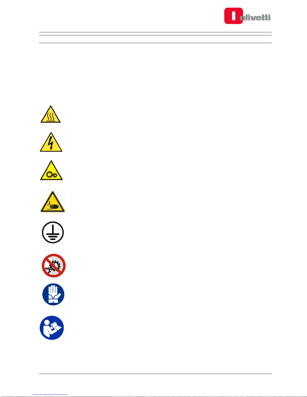
SAFETY WARNINGS
Pictograms are applied to certain parts of the printer as safety warnings, these warnings must be observed
attentively by anyone preparing to use the printer.
HOT SURFACES
The hot surfaces warning symbol warns of the presence of devices having high temperatures.
Always exercise great care and wear safety gloves when manipulating heated components
HIGH VOLTAGE HAZARD
Exercise great caution: live electrical equipment
MOVING PARTS
Moving parts present - approach with great care
CRUSHING/PINCHING HAZARD
Do not introduce your hands into the machine while it is functioning
GROUND TERMINAL
Equipment ground connection points
REMOVAL OF MECHANICAL GUARDS PROHIBITED
Do not open the front door during the printing process. Do not remove the protective bellows of
the worm screw.
GLOVES
When carrying out preparatory procedures for printing or maintenance routines, the device may
be hot therefore you must always wear gloves to avoid burns.
READ INSTRUCTIONS
For the correct operating instructions you must read the User Manual provided on the SD Card
supplied with the product.
Page 6

vi User Manual 596806-02
TRANSPORTATION AND INSTALLATION:
At least two persons are requested for transporting the 3D printer. The weight of the printer with packing is
approximately 31 Kg.
Personnel charged with handling the shipment must wear safety gloves.
When lifting or moving the 3D printer, or any of its parts, first make sure that the operating area is completely
clear, leaving also a sufficiently large safety area around it to avoid damaging persons or objects that could come
within the area for manoeuvring the load.
Note: conserve the original product packaging in case you will need it for shipping the product in the future.
Observe the following instructions:
the printer must be placed on a flat stable surface (not supplied with the printer) of sufficient load-bearing
capacity to support its weight, and at a minimum floor height of 60 cm.
fans are provided for cooling the electronic parts. Make sure there is sufficient free space around the printer
to allow adequate air circulation for ventilation. You must leave a distance of at least 60 cm from walls or
other objects.
do not position the printer near sources of heat, water or other freely moving liquids.
do not expose the printer to dust, rain, humidity or vapour.
the operating environment temperature must be maintained at 20°C approximately.
by law the equipment must be grounded; use exclusively the power cord provided with the product without
extension cords.
to protect the printer during transportation, the print carriage is locked into position with strapping tape: before
starting to print cut and remove this tape.
USE
The 3D IoT printer is not suitable for use by persons under 14 years of age, and anyway always under the
direct supervision of an adult. Make sure that children do not tamper or play with the equipment.
The printer is intended for use by operators who have received adequate training.
Use the power supply voltage indicated in the technical specifications. The power cord must never be pulled,
subjected to weights or brought into contact with sharp objects.
Do not touch the equipment with parts of the body that are wet; footwear must always be worn.
Do not smoke, use naked flames or create sparks in the vicinity of the printer.
If the printer malfunctions or fails, do not attempt to use it again until it has been repaired.
When the 3D IoT printer is functioning, certain parts generate high temperatures (printhead, heated table if
present); there are also moving parts which could cause injury if touched accidentally during operation. You
must therefore observe the following warnings carefully:
Whenever any operation is carried out on the printer - whether for installation or maintenance purposes
- always first switch off and disconnect the equipment from the electrical socket. Before proceeding,
wait for all parts that may have become heated during the previous operation to cool down.
The machine must be used exclusively with the front door closed; printing IS NOT interrupted
automatically when the front door is opened, therefore this instruction must be observed with maximum
attention.
The front door is fitted with a lock and key to prevent unauthorised access.
The key must be conserved in a safe place by those responsible for its safe-keeping.
Page 7

596806-02 User Manual vii
The heated parts must be left to cool for a certain length of time at the end of printing or when printing
is interrupted: leave the machine to cool down (approx. 5 minutes) before attempting to access the
printing area. It is good practice to check that the machine temperature shown on the front display (of
printhead and, if heated, table) is less than 40°C before attempting any interventions. Do not touch the
printhead as it may be very hot after use.
Do not wear rings, wristwatches, jewellery or loose/baggy clothing, such as scarves, unbuttoned jackets
or tops with open zips, that could become entangled in the moving parts. Keep hair tied back.
Do not insert your hands between the moving parts.
Do not use the printer for a different purpose to that for which it is designed, as specified in the User
Manual.
Do not attempt to clean the printer while it is in operation. Clean the outside of the printer only using a
soft cloth, without the use of corrosive chemical products, solvents or strong detergents, and only after
having disconnected the printer from all external power supplies and other cables.
It is advised not to leave the printer unsupervised during printing
Make sure that the room where the printer is installed is well ventilated.
Before launching a print job make sure that no objects or scrap materials are left inside the printer (such
as lacquer, rags, maintenance tools, materials removed manually,..).
Exercise the greatest care when removing the worked piece from the glass table using sharp or pointed
objects to avoid injuring yourself in the process. Use of knives or cutters for removing worked pieces
from the glass table is strongly discouraged, even in the case of small pieces.
Although the glass is tempered it is still fragile and great care must be taken when handling it.
If required, clean or change the print nozzle. The extruder must be hot to allow the residual material
inside the head to soften and not create an obstruction during replacement procedures : for all
operations always wear heat protection gloves.
Page 8

vi User Manual 596806-02
MAINTENANCE OPERATIONS SAFETY STANDARDS
Printer maintenance must be carried out exclusively by adequately trained personnel.
The principal rules to follow when carrying out maintenance operations on the printer are:
Before carrying out any interventions on the printer, make sure that it is in a safe condition.
Do not wear rings, wristwatches, jewellery or loose/baggy clothing, such as scarves, unbuttoned jackets or
tops with open zips, that could become entangled in the moving parts. Keep hair tied back.
Do not touch the equipment with wet body parts and never without shoes.
Do not use naked flames or pointed/sharp instruments for cleaning purposes.
Do not smoke.
Do not insert hands between moving parts.
When carrying out printer installation or maintenance operations, always switch off and disconnect the printer
from the electrical socket. Wait for all parts heated during the preceding operation to cool down. Leave the
machine to cool (approx. 5 minutes) before attempting to access the printing area. It is a good rule to check
that the machine temperature on the front display (of printhead and, if heated, the table) is under 40°C before
attempting any interventions. Do not touch the printhead as it could be very hot after operation.
If necessary, clean or replace the print nozzle. The extruder must be hot to allow the residual material inside
the head to soften and not create obstructions during replacement operations: when operating always
wear safety gloves for heat protection
Switch on the printer only when necessary and following the instructions in the Manual, remembering to
proceed always with maximum care
Do not attempt to clean the printer while it is functioning. Clean the outside of the printer with a soft cloth and
without using corrosive chemical products, solvents or other strong detergents. Before any cleaning
operation, disconnect the printer from all external power supplies and any connected cables.
Be very careful when attempting to remove the printed object from the glass table using sharp or pointed
objects to avoid injuring yourself in the process. Use of knives or cutters for removing items from the glass
table is strongly discouraged, even in the case of small objects.
Although the glass is tempered it is still fragile so always be very careful when handling it.
At the end of servicing operations, make sure that you remove any tools or rags used from inside the printer
and eliminate all accumulated residues
When you finish servicing operations, return the door key to the person responsible for its safe-keeping.
Page 9

596806-02 User Manual ix
PACKAGE CONTENTS
The following items are contained in the Olivetti 3D IoT printer package:
1 3D IoT Printer
2 Front door keys
1 SD Card, 4GB or greater
3 Allen Keys (1.5 mm, 2.5 mm, 5 mm)
1 Hex key, size 8
1 key, 12 mm
Washer, pin, sleeve and hex head screw for filament bobbin mount point
1 Spatula for removing printed pieces
1 AC Power Cord
1 PLA Bobbin, diameter 1.75 mm, weight 1 Kg
1 CE, WEEE, Safety Declarations leaflet
Page 10

vi User Manual 596806-02
This page is intentionally left blank
Page 11

596806-02 User Manual 1-1
Chapter 1 – INTRODUCTION
PRODUCT OVERVIEW
The Olivetti 3D IoT printer exploits Fused Filament Fabrication (FFF) technology to create 3-D objects through
layer upon layer deposition of material in 2-D.
This chapter describes the printer design and introduces the terminology that will be used in the rest of the
manual.
.
Page 12
1-2 User Manual 596806-02
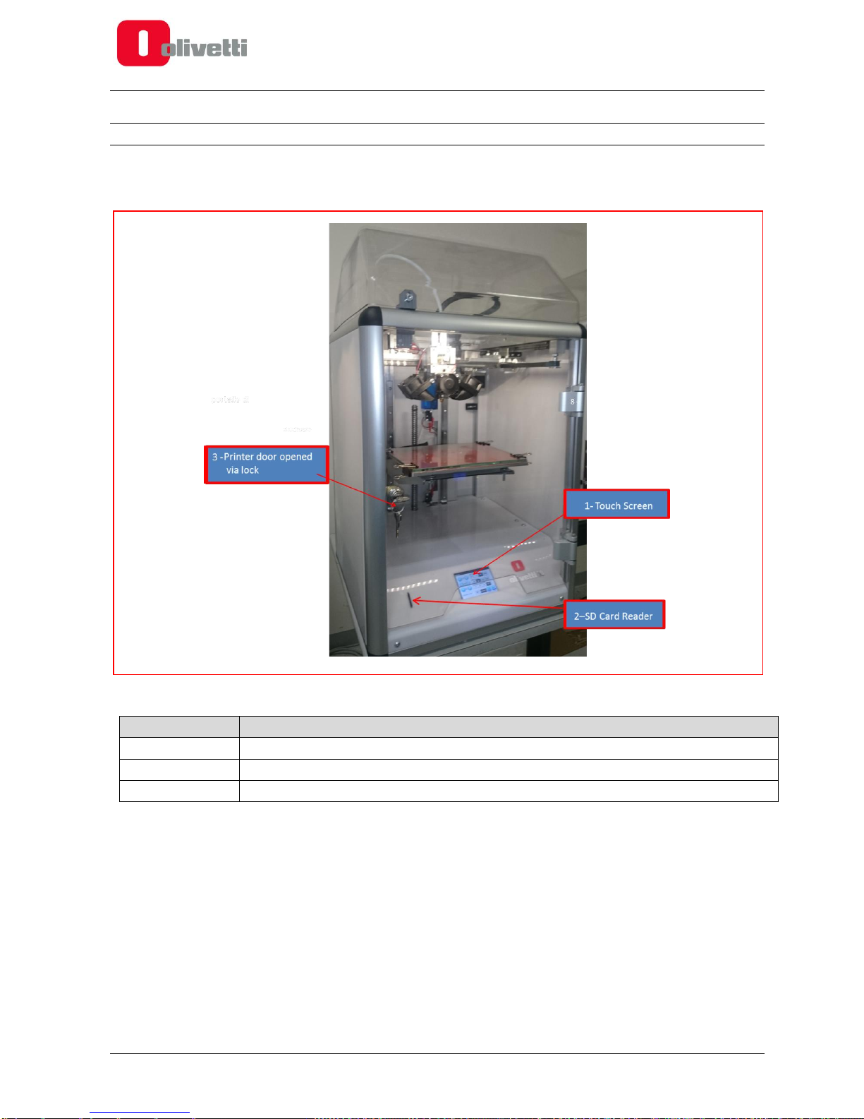
PRINTER DESIGN
The main printer controls are located at the front of the printer where there is also a door fitted with a lock
for accessing the inside of the printer.
Figure 1-1 Front view
REFERENCE
DESCRIPTION
1
Touch screen display
2
SD card reader
3
Printer door with lock
Page 13

596806-02 User Manual 1-3
The upper dome-shaped casing can be opened by releasing the catch from the inside, applying light pressure
on its lower part.
Figure 1-2 Internal catch for locking/unlocking the upper dome
Page 14

1-4 User Manual 596806-02
When the front door is opened, the extruder assembly can be seen clearly.
Figure 1-3 Extruder assembly
REFERENCE
DESCRIPTION
1
Extruder
2
Fans for cooling material being printed
3
Extruder cooling fan
Page 15

596806-02 User Manual 1-5
Figure 1-4 Hot-end close-up
REFERENCE
DESCRIPTION
1
Nozzle
2
Hot-end
3
Hot-end set screw
4
Filament feeder assembly
Page 16

1-6 User Manual 596806-02
Figure 1-5 Feeder assembly terminals and pressure adjustment screw
REFERENCE
DESCRIPTION
1
Bowden quick release coupling
2
Filament pressure adjustment screw
Page 17

596806-02 User Manual 1-7
At the rear of the machine, there is the housing for the bobbin containing the filament, the power switch and
power socket.
Figure 1-6 Rear view
REFERENCE
DESCRIPTION
1
Bobbin holder
2
Feeder
3
Power switch
4
Power socket
Page 18

1-8 User Manual 596806-02
PRINTER AXES ORIENTATION
The printer axes origin, known as the Home position, is the front left corner of the printing table.
Figure 1-7 Orienting the Olivetti 3D IoT printer axes
Starting from the origin, the positive direction of the X axis ordinate is from the left of the worktable to the right
side, the positive direction of the Y axis ordinate is from the front door towards the rear of the machine, while the
Z axis is oriented vertically, its ordinate increasing as the printing table descends from the top downwards.
Page 19

596806-02 User Manual 1-9
This page is intentionally left blank
Page 20

Page 21

596806-02 User Manual 2-1
Chapter 2 – PRINTER SETUP
PREPARING YOUR PRINTER
This chapter describes the procedures that must be followed to configure correctly the Olivetti 3D IoT printer and
prepare it for the successive printing phase.
Unblocking the extruder assembly
To protect the printer during transportation, the print carriage is fixed securely in position by plastic banding.
This banding must be removed before attempting to print.
Powering on the printer
Connect the printer to a 220V power supply socket using the power cord supplied in the kit. Switch on the printer
at the power switch at the back of the machine.
Figure 2-1 Power socket and power switch
Page 22

2-2 User Manual 596806-02
Touch Screen Display
When the printer is powered on, the main printer status information is displayed on the 3.5” Touch Screen.
Figure 2-2 Touch Screen Display in Rest mode (Desktop Menu)
Current Extruder
temperature setting
New Extruder
temperature setting
Current Printing Table
temperature setting
New Printing Table
temperature setting
Menu Key
Current Acceleration
setting (metres per
second squared)
Current Flow value
setting
New Flow value
setting
New Acceleration setting
Auto Home
Page 23
596806-02 User Manual 2-3
Aligning the printing table
To obtain good printing quality it is essential to ensure that the first layer deposited is distributed in a uniform
manner on the printing table.
To achieve this, you must ensure that the printing table is aligned correctly.
Although the printer has been set up correctly at the factory, it may have been subjected to vibrations during
transportation making it necessary to repeat this procedure.
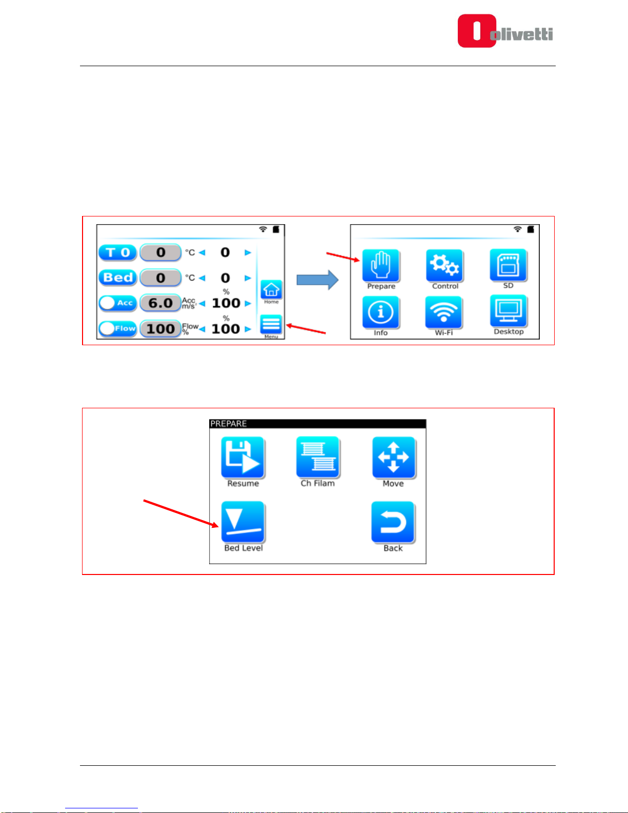
To align the printing table:
1. Starting from the Desktop Menu, press the Menu key and then, in the next screen, press the Prepare key.
Figure 2-3 From the Desktop Menu, select Menu then Prepare
2. From the Prepare Menu, select the Bed Level command.
Figure 2-4 Prepare Menu with Bed Level command
Page 24

2-4 User Manual 596806-02
3. The Touch Screen displays the Bed Levelling message while the extruder assembly takes up the Home
position.
Figure 2-5 Bed Levelling Display
4. Touch the display at bottom left (Position 1 in Figure 2-5). The extruder assembly moves to this first
adjustment point.
5. Try to pass a normal sheet of paper, folded in two, between the extruder nozzle and the tempered glass
table (Figure 2-6).
If the paper moves freely between the nozzle and the glass, you need to concentrate on the self-locking nut
(Figure 2-7), turning it a few degrees in the clockwise direction to bring the table nearer to the nozzle
eliminating any space between the glass, the paper and the nozzle.
If the opposite is true, i.e. the nozzle is too near the glass (you cannot insert the sheet), then you must turn
the nut in the opposite direction (i.e. anticlockwise) so as to set the correct amount of space between the
nozzle and the printing table.
Figure 2-6 Use a sheet of paper to check the distance between the extruder nozzle and the tempered glass
1 2 3
4
5
Page 25

596806-02 User Manual 2-5
Figure 2-7 Adjustment nut locations
6. After having completed the first adjustment, touch the display this time at Position 2. The extruder assembly
moves to this second adjustment point.
7. Repeat the adjustment in the same way as illustrated in step 5, working on the related selflocking nut.
In all, there are 4 adjustment points for each of which you must carry out adjustments as described in step 5.
8. To conclude, check the distance between the extruder nozzle and the tempered glass at the centre part of
the glass, touching the display at Position 5.
9. Repeat the whole operation a second time, that is, as many times as necessary, until the distance between
the extruder nozzle and the tempered glass is correct for all positions.
10. After completing adjustments, press the “Back” key to conclude the adjustment procedures.
NOTE: The first layer printed is normally thicker than the subsequent layers (when set appropriately in
the Slicing software). This feature is able to compensate for any small misalignments.
NOTE: the tempered glass does not have centesimal planarity, therefore the material for the first layer
may not deposited in a perfectly uniform way. It is essential however to ensure that the outer lines are
uniform to ensure good adhesion with the table. The centesimal differences in height are compensated
for in the next 2-3 layers.
WARNING: If the height adjustment operation is not carried out correctly, print quality could be poor.
In extreme cases, it could also result in collisions between the hot-end and the printing table, with the
risk of damaging the machine.
Page 26

2-6 User Manual 596806-02
The table below provides some examples of problems caused by incorrect alignment of the printing table and
provides suggestions for how they can be resolved.
Problem
Reason
Solution
Nozzle touches the glass
Glass is too near the nozzle
Turn the nuts of the printing table a
few degrees in the anticlockwise
direction to increase the distance
between nozzle and printing table
Material is not able to flow out of the
nozzle correctly
Glass is too near the nozzle
Turn the nuts of the printing table a
few degrees in the anticlockwise
direction to increase the distance
between nozzle and printing table
The material flows out of the nozzle,
but the line printed for the first layer
is extremely narrow and too “spread
out” width-wise
Glass is too near the nozzle
Turn the nuts of the printing table a
few degrees in the anticlockwise
direction to increase the distance
between nozzle and printing table
The material flows out correctly, but
the “line” deposited is very narrow in
width and has a cylindrical section, it
comes away from the printing table
easily during successive printing
operations.
Glass is too far from the nozzle
Turn the nuts of the printing table a
few degrees in the clockwise
direction to deincrease the
distance between nozzle and
printing table
The material flows out correctly but
can be seen to “jump” slightly before
sticking to the printing table
Glass is too far from the nozzle
Turn the nuts of the printing table a
few degrees in the clockwise
direction to deincrease the
distance between nozzle and
printing table
On visual examination, the line
deposited for the first layer is
irregular varying in both thickness
and width
The glass has not been aligned
correctly: a line which is too thick
indicates that the distance
between the nozzle and printing
table is too small. A line which is
not thick enough indicates that
the distance between the printing
table and the nozzle is too great
Repeat the procedure for adjusting
the printing table, then adjust the
printing height.
Page 27

596806-02 User Manual 2-7
Adjusting the printing nozzle height
To ensure correct printer operation and optimise printing quality, apart from aligning the printing table, it might
be useful to adjust also the printing nozzle height.
Although this procedure has already been carried out at the factory, you may need to repeat it as the printer may
have been subjected to jolts during transportation.
To adjust the nozzle height, first unblock the hot-end unit by unscrewing the set screw on the extruder assembly
that can be found under the fans (use the 2.5 mm allen key supplied with the machine).
Figure 2-8 Hot-end assembly setscrew
With the set screw loosened the hot-end block is free to move; adjust the nozzle to a distance of 0.10mm from
the tempered glass table.
This adjustment can be achieved as described in the previous section, by placing a paper sheet folded in two
between the nozzle and the table. Rest the nozzle on the sheet and check that the distance between the
extruder nozzle and the tempered glass is correct, then tighten the setscrew again using the 2.5 mm allen key
to block the hot-end assembly again.
WARNING: If the height adjustment is not carried out correctly, printing quality could be poor or, in
the worst case, it could cause a collision between the hot-end and the printing table with damage to
the machine.
WARNING: The height adjustment procedure must be carried out with the nozzle in a clean
condition, free from plastic residues.
Page 28

2-8 User Manual 596806-02
Loading the filament bobbins
To correctly load the filaments containing the materials for printing, follow the procedure below:
1. Unscrew by hand the protection screw mounted at the rear of the printer.
2. Insert the washer and cylindrical tube onto the hexhead screw.
3. Tighten the screw by hand (do not use an allen key for tightening as you may tighten the screw too much).
Figure 2-9 Protective screw to remove
Figure 2-10 Bobbin with its holder components
Page 29

596806-02 User Manual 2-9
Figure 2-11 Putting bobbin with filament into position
4. Insert the bobbin with the filament onto the bobbin holder. With the end of the filament trailing to the bottom
left of the bobbin, feed the filament into the input slot to the feeder. This means that, looking at the machine
from the back, when the filament is pulled upwards the bobbin rotates in a clockwise direction.
5. To minimise the possibility of the bobbin shifting sideways during printing, a fork-like wedge can be inserted
onto the fixing nut, as shown in the figure below. The file for printing the wedge is stored on the SD Card
supplied in the printer package.
Figure 2-12 Inserting fork-like wedge (optional)
6. Cut the filament at an angle of approximately 45° and straighten out the first 5 centimetres. This makes
inserting the filament into the feeder and the end-of-filament sensor easier. Insert the filament into the lower
feeder slot and push it through, sliding it inside the feeder. When the filament enters the end-of-filament
sensor (mounted inside the printer) you may notice a certain amount of resistance impeding movement – in
this case push the filament with determination to overcome resistance.
Page 30

2-10 User Manual 596806-02
Figure 2-13 End-of-filament sensor (inside printer)
If an obstacle is perceived during the passage of the filament inside the sensor, it is advisable to withdraw
the filament downwards, push downwards the teflon tube inserted in the upper part of the sensor (see figure
2-14) , until the tube itself can not be pushed further down, and then try again to insert the filament.
Figure 2-14 Pushing downwards the teflon tube inserted in the upper part of the sensor
7. Continue pushing until the filament appears at the feeder unit located at the front of the machine inside the
extruder assembly. If the filament does not feed through easily, remove the filament duct from the feeder,
pressing the black gasket of the bowden lightly between two fingers of one hand, while pulling slowly the
white duct with the other hand.
Pull the filament out and insert it into the feeder unit. Pressing slightly, put the duct back into place.
Figure 2-15 Removing the feeder duct and passing through the filament
Page 31

596806-02 User Manual 2-11
8. Adjust the hot-end temperature to the correct operating value for the type of filament loaded (for example,
200°C for PLA).
To adjust the hot-end temperature:
from the Start menu, press on the RIGHT arrow of the T0 line until the required temperature value is
displayed.
Figure 2-16 Setting the temperature of the hot-end
9. Pass the filament inside the feeder unit and push it through for approximately 10 cm until it comes out of the
printing nozzle.
Figure 2-17 Inserting the filament into the hot-end
WARNING: During the first manual extrusion, you may find residual material from a preceding
printing process; this is normal because the machine is subjected to testing before being packaged.
Page 32

2-12 User Manual 596806-02
The following table gives some examples of error conditions that could be caused by incorrectly loading the
filament with possible solutions.
Problem
Reason
Solution
The filament is not fed through by
the feeder unit. Examining the
filament by eye it seems
unblemished without any
“notches” left by the gears.
Insufficient pressure as a result
of which the filament is not
pressed correctly against the
gear.
Increase the pressure of the feeder
unit by means of the adjusting grub
(see Figure 2-17), avoiding setting
too high a pressure that could
deform the filament
The filament is fed by the feeder
assembly, but occasionally
unexpected “slips” occur and
material is not extruded.
Examining the filament by eye it
can be seen to be deeply notched
or consumed by the gear.
Too much pressure resulting in
the filament being squeezed to
hard against the gear.
Decrease the feeder tightness by
means of the adjusting grub (see
Figure 2-17)
Figure 2-18 Adjusting grub of feeder unit
Page 33

596806-02 User Manual 2-13
Preparing the printing table
The last operation to accomplish before proceeding with printing is to prepare the printing table.
If you are going to use the table covered with PEI (polyetherimide) film - already mounted on the 3D IoT printer
- no preparatory steps in fact are needed for the table, nor to increase the adhesion of material to the
table.
SPECIAL CASES
when printing using technical materials such as ABS, ASA and Nylon-based materials (eg
Carbonium), it is advisable to improve adhesion by using a special 3D printing spray, such as the
Dimafix. For how to use the spray, see the instructions below for using lacquer.
when printing using flexible materials such as Rubber HS, it is advisable to print on the glass surface
instead of the PEI surface, by following the instructions below.
In situations where you want to use the tempered (4 mm) glass printing table WITHOUT the PEI film, you need
to be aware that, under normal conditions, plastic does not stick to glass. For this reason, to improve adhesion,
you are advised to use a special 3D printing spray or a common hairspray to create a “sticky” film to which the
plastic can adhere (Strong Hold hairspray is recommended). To prepare the table and make applying the film
of hairspray easier, you have to remove the glass from the printer.
To do this, proceed as follows:
1. lower the table following these steps:
I. Starting from the Desktop Menu, press the Menu key and then, from the next screen, the
Prepare key.
Figure 2-19 From the Desktop Menu, select Menu then Prepare
II. From the Prepare Menu, select the Move command
Figure 2-20 Prepare Menu with Move command
III. In the Move menu, set the following values for the movement parameters:
Page 34

2-14 User Manual 596806-02
DISTANCE (mm): 100.
SPEED (mm/sec): 500
ACCELERATION (mm/sec2): 12
IV. Press the RIGHT arrow on the Z row to lower the table:
Figure 2-21 Move command for Z axis
2. when the table has completed its movement, remove the four clamps by pressing lightly on their metal
wings.
3. after removing the clamps, lift the glass table, reverse it and place it gently on a flat surface.
4. spray on the glass the lacquer (strong/extra strong hold) from a distance of approximately 15 cm. The
best procedure is to spray across the table first horizontally and then perpendicularly. Be sure to carry
out this operation in a well ventilated room, far from inflammable objects and other objects that could
become covered with lacquer.
5. wait a few seconds until the lacquer dries (it is dry when no fingerprints are left) and proceed to remount
the table fixing it again with the four clamps.
To resume printing on the PEI surface, repeat the removal operation of the plate described above, clean the
glass surface removing the lacquer residues (using a degreaser) and replace the plate with the PEI surface
facing up.
WARNING: Although the glass is hardened it is still fragile, so you must always be very careful when
handling it.
Page 35

596806-02 User Manual 3-1
Chapter 3 – PRINTING WITH THE OLIVETTI 3D IOT
PRINTING WITH THE OLIVETTI 3D IOT PRINTER
After you have carried out the printer adjustments and loaded the bobbin with the filament, the printer is ready
to use.
Printing a test piece
On the SD card in the kit, you can find some files that can be used for executing a printing test to gain confidence
with using the printer.
WARNING: if the SD Card cannot be recognised / read, check the position of the lock switch on the
side of the card, making sure it is in the unlocked position (that is, enabled for reading and writing).
To print a test piece:
1. Insert the SD CARD into the slot at the front of the printer
2. Starting from the Desktop Menu, press the Menu key and then, in the next screen, the SD key
Figure 3-1 From the Desktop Menu, select Menu then SD
3. Select the file to print (e.g. Logoolivetti1.gcode)
4. The machine now starts the automatic printing procedure reading the GCODE file indicated, executing all
phases. You can follow the process from either the Info menu or, naturally, looking through transparent
door of the printer.
When printing is launched, the printer executes the following procedure:
1. Homes all axes,
2. Heats the extruder and table, until the temperature required is reached
3. Extrudes a small quantity of material for loading into the extrusion chamber
4. Moves to the printing area, and starts the procedure for printing layer on layer.
5. When printing completes, the machine sends the carriage to the Home position. It then switches off the
heaters to allow the machine to return to the normal environmental temperature.
NOTE: Files in the printing format supported by the Olivetti 3D IoT printer always have the
extension .GCODE.
Page 36

3-2 User Manual 596806-02
CREATING PRINTABLE FILES FOR THE OLIVETTI 3D IOT PRINTER
This section describes the steps necessary for producing GCODE files that can be printed using the Olivetti 3D
IoT printer.
Creating a 3D model
The first thing to do is create a three-dimensional model of the object you want to print.
To create the model you can use both commercially-available 3D CAD drawing software or free software, such
as OpenSCAD, Blender, SketchUp or FreeCAD.
Alternatively, you can also download ready-to-use 3D models, available for free on Internet sites such as
Thingiverse and GrabCAD.
There are various file formats for 3D models however .STL (STereoLithography) format is recommended for
generating and downloading models given that it is the most commonly used format. It will be easily managed
by the programs you will have to use afterwards for generating the GCODE for printing in 3D.
Creating GCODE starting from 3D model
Once the 3D model in STL format is ready, it must be further processed to make it printable through
transformation in GCODE.
Transformation from .STL to .GCODE using special SW called slicers.
Slicers are programs that divide up the 3D model into manageable sections that the 3D printer is able to deposit
on a work table.
Page 37

596806-02 User Manual 3-3
Many types of slicers exist, however the most recommended are Cura, and in particular, Simplify3D.
The sample files saved on the SD Card have been generated using Simplify3D. For the profiles provided by
Olivetti for simplifying slicing operations you must use Simplify 3D.
Figure 3-2 3D model being converted by Simplify3D
After generating the GCODE file using the slicer, copy it onto the SD card. Now insert the card into the Olivetti
3D IoT printer to print the model.
WARNING: if the SD Card cannot be recognised / read, check the position of the lock switch on the
side of the card, making sure it is in the unlocked position (that is, enabled for reading and writing).
Page 38

3-4 User Manual 596806-02
GCODE PRINTING
To print your GCODE, proceed as previously explained in the section related to test piece printing, that is:
1. Insert the SD CARD into the slot at the front of the printer
2. Starting from the Desktop Menu press the Menu key and then, in the next screen, the SD key
Figure 3-3 From the Desktop Menu, select Menu then SD
3. Select the file to print (e.g. Logoolivetti1.gcode)
4. The automatic printing procedure starts, reading the GCODE file indicated and executing all the phases.
You can follow the process from the Info menu or, naturally, observing it directly through the transparent
printer glass.
Generating overhang supports
Portions of a model that cannot be printed using the FFF printing process, without the provision of an
adequate support underneath, are defined as overhang.
As in FFF technology layers are deposited one on top of the other, each layer must have an adequate
support underneath.
If your 3D model has planes or surfaces that rise upwards with an inclination of over 50° approximately
with respect to the vertical plane (40° from the table), the layer deposited may not have sufficient support
underneath resulting in it collapsing downwards, compromising printing quality.
To resolve the problem of overhang, whenever required the slicing software is able to generate material
supports automatically (on the basis of user-defined parameters).
At the end of printing process this additional material must be removed manually.
Page 39

596806-02 User Manual 3-5
SUSPENDING AND INTERRUPTING PRINTING
1. Suspending printing manually
Using the menus you can suspend or cancel printing while it is in progress.
To suspend printing, select the “Pause” key from the Desktop Menu
Printing will be suspended and the extruder assembly moved to the “wait” position.
Figure 3-4 Suspending printing
After printing is suspended, the “Pause” screen appears on the display
Figure 3-5 “Pause” Screen
From this screen you can:
a. Restart printing by pressing “Restart”
b. Stop and save the print job in progress by pressing “Stop&Save”.
Printing can then be restarted in the following manner:
from the Desktop Menu, select Menu
from the next menu, select Prepare
from the next menu, select “Resume”. The printer:
heats the extruder and printing table to the appropriate temperature, at the end displaying this
screen:
Page 40

3-6 User Manual 596806-02
Figure 3-6 “Resume Saved Job”, with Restart command
now select the “Restart” command. The printer begins to extrude slowly, filling the nozzle to
the appropriate level.
During this phase, the screen below is shown on the display (Figure 3-7). Check that the
printer is extruding in a regular manner then confirm the restart operation by selecting
“Restart”.
To avoid imperfections in the printed object, you are advised to remove by hand the filament
that is extruded during the restart phase, that is before the nozzle and table come into contact
again. For this operation you must always wear protective heat-resistant gloves and pay
maximum attention to the nozzle, avoiding all contact with it.
Figure 3-7 “Pause” Screen showing Restart command
c. the third option in the “Pause” screen is Change Filament that is activated by selecting “Ch Filam”.
When this command is selected, the following screen appears on the display:
Figure 3-8 “Change Filament” screen
Page 41

596806-02 User Manual 3-7
The machine automatically heats the extruder to the appropriate temperature for this operation. Once the
temperature has been reached, proceed as follows:
I. using the down arrow, activate extrusion of a small quantity of material
II. use the up arrow to retract the filament to be replaced.
After removing the bobbin with the filament, proceed to load the new filament (see section
“Loading the filament bobbins” in Chapter 2).
On completing this operation, select the “Back” key then “Restart” in the next screen
Figure 3-9 “Pause” Screen with “Restart” key
Page 42

3-8 User Manual 596806-02
2. Suspending printing automatically
Printing can be suspended automatically under two conditions:
a. end-of-filament sensor detects filament is finished.
In this case, printing is suspended. The printer retracts any residual filament before moving to the
pause position, as indicated by these two screens:
Figure 3-10 End-of-filament screens
Select “Ch Filam” from the second screen, replace the empty bobbin, then restart printing following the
procedure outlined in the previous section.
Page 43

596806-02 User Manual 3-9
b. power supply failures
when the power supply is interrupted, the mini-UPS integrated in the printer comes into function:
printing is suspended, the printer retracts the residual filament and then switches off. During the save
procedure the screen below is shown on the display:
Figure 3-11 Screen that appears for power interruptions
Printing can be restarted following this sequence:
from the Desktop Menu, select Menu
from the next Menu, select Prepare
from the next Menu, select “Resume Saved”.
Figure 3-12 From the Desktop Menu, select Menu then Prepare
Figure 3-13 From the Prepare Menu, select the Resume command
From this moment, the printer performs the procedures described in the earlier section for restarting
printing after a manual suspension.
Page 44

3-10 User Manual 596806-02
REMOVING PRINTED PIECES
When printing concludes, wait until the printing table returns to the normal environmental temperature before
attempting to remove the printed part.
At this point, proceed as follows:
lower the table using this sequence:
1. Starting from the Desktop Menu, press the Menu key then, in the next screen, the Prepare key
Figure 3-14 From the Desktop Menu, select Menu then Prepare
2. From the Prepare Menu, select the Move command.
Figure 3-15 Prepare Menu with Move command
3. In the Move screen, set the following values for the movement parameters:
DISTANCE (mm): 100
SPEED (mm/sec): 500
ACCELERATION (mm/sec2): 12
Page 45

596806-02 User Manual 3-11
4. Press the RIGHT arrow on the Z row to lower the table:
Figure 3-16 Move Command for Z axis
when the table has stopped moving, proceed to remove the printed piece. If necessary use the spatula
supplied in the kit, taking care not to damage the PEI film covering the printing surface.
NOTE: The printing table is composed of 4 mm tempered glass. Although it is a safe heat-resistant material,
it is still fragile. You must therefore be very careful when handling it. For printing always use the special glass
supplied with the machine.
Page 46

3-12 User Manual 596806-02
MENUS AND NAVIGATION
From the Olivetti 3D IoT printer User Interface you can access all commands necessary for carrying out printer
adjustments, maintenance operations and printing itself.
From the Desktop Menu you can display and modify the principal parameters:
Figure 3-17 Touch Screen Display in rest mode (Desktop Menu)
You can modify the settings using the arrows present on each of the rows T0, Bed, Acc and Flow. Press
on the left arrow to decrease a value or on the right arrow to increase it.
The two right-hand keys perform the following functions:
Home key: the machine performs the auto homing manoeuvre, that is, it carries the printhead and the
printing table to the rest position
Menu key: provides access to the Main Menu
Current Extruder
temperature setting
New Extruder
temperature setting
Current Printing Table
temperature setting
New Printing Table
temperature setting
Menu Key
Current Acceleration
setting (metres per
second squared)
Current Flow value
setting
New Flow value
setting
New Acceleration setting
Auto Home
Page 47

596806-02 User Manual 3-13
MAIN MENU
The Main Menu can be accessed by pressing the Menu key that appears at the bottom right of the start
screen /Desktop Menu.
Figure 3-18 Main Menu
From the Main Menu you can select:
Prepare to access its related submenu
Control to access its related submenu
SD to access the contents of the SD Card
Info: to access information on the printer and its use
Wi-Fi: to access its related submenu
Desktop to return to the Desktop Menu
Page 48

3-14 User Manual 596806-02
PREPARE MENU
The Prepare Menu allows you to carry out the main machine adjustments. Select Prepare to access the
following submenu:
Figure 3-19 Prepare Submenus
Resume resumes the last saved job, as previously described in the section “Suspending and
interrupting printing”
Change FIlament procedures for changing the filament, as previously described in the section
“Suspending and interrupting printing”
Move movement of X, Y and Z axes
Bed Level procedures for levelling the printing table, as previously described in the section “Aligning
the printing table”
Back Returns you to the Main Menu
MOVE COMMAND
When you select the Move command, the following screen is displayed.
Figure 3-20 Move Submenu
The Distance, Speed and Acceleration parameters on the right of the display allow you to define the distance
and speed of movement of the Axes and of the Extruder:
DISTANCE (mm): you can set the movement from a minimum of 0.1 mm to a maximum of 100 mm.
SPEED (mm/sec): you can set the speed from a minimum of 10 mm/sec to a maximum of 500 mm/sec
ACCELERATION (mm/sec2): you can set the acceleration from a minimum of 3 mm/sec2 to a maximum
of 12 mm/sec2
Page 49

596806-02 User Manual 3-15
After adjusting the previously mentioned parameters, you can move the extruder assembly (X and Y) and
the printing table (Z), and turn the filament (E0) feeder gears by pressing the arrows on the X, Y and Z
rows:
X Row: press the left arrow to move the extruder assembly to the left or the right arrow to move it to
the right
Y Row: press the left arrow to move the extruder assembly towards the front door or press the right
arrow to move the extruder assembly towards the back of the printer
Z Row: press the left arrow to move the printing table upwards or the right arrow to move it downwards
E0: press the left arrow to turn the feed gears upwards (filament retraction) or the right arrow to move
the feed gears downwards (filament extrusion)
The Motor On/Off key allows you to enable or disable the motors: when you need to move the motors
manually select MotorOff to switch off the motors.
WARNING: move the axes slowly and carefully to avoid self-induction of currents that could damage
the axes controller boards.
Page 50

3-16 User Manual 596806-02
CONTROL MENU
The Control menu shows the basic printer adjustment parameters.
Given that this type of adjustment must be carried out exclusively by expert users, they can’t be modified
by the user.
Figure 3-21 Control Submenu
Page 51

596806-02 User Manual 3-17
SD CARD MENU
Selecting SD in the Main Menu, you can access the SD Card Menu and view the list of .GCODE files present in
memory.
Figure 3-22 Main Menu with SD key
Figure 3-23 Menu SD
To select a file and print it, scroll through the list using the arrows then confirm your selection by pressing the
OK key.
Press the Menu key to return to the Main Menu.
Page 52

3-18 User Manual 596806-02
INFO
Figure 3-24 Main Menu with Info key
When Info is selected in the Main Menu, the Olivetti3D access screen is displayed. Touching this screen you
can access printer information including usage data:
Figure 3-25 Access screen
Figure 3-26 Information
Information provided :
a. Firmware version
b. Printer Serial Number
c. Power-On time total number of hours powered on
d. Printing time total number of printing hours
e. Extruder 0 Filament: Number of metres of filament extruded
f. Parameter mode: Parameter profile set
Page 53

596806-02 User Manual 4-1
Chapter 4 – WI-FI CONNECTIONS
SETTING AND USING WI-FI CONNECTIONS
An Access Point is integrated in the 3D IoT printer, allowing wireless connections to be set up with devices such
as PCs, Tablets and smartphones (running either operating system, iOS or Android).
When the Wi-Fi key is selected from the Main Menu, the Wi-Fi Management menu appears:
Figure 4-1 Main Menu with Wi-Fi key
Figure 4-2 Wi-Fi menu
Pressing the “Off” key in the Wi-Fi Menu, the related function is activated.
In the lower half of the display the following messages appear in sequence :
Wi-Fi Module booting Wi-Fi module startup operations
SSID Scanning searching for the Service Set IDentifier, that is, the 32-character alphanumeric key
identifying univocally the wireless network generated by the Access Point integrated in the printer
Starting AP Mode starts the Wi-Fi Access Point functionality in Access Point (AP) mode.
At the end of these setup operations, the Wi-Fi module is ready.
Page 54

4-2 User Manual 596806-02
ACCESS POINT MODE
When the Wi-Fi module is powered on it activates Access Point mode.
In the lower half of the display, the “name” of the Wi-Fi network generated by the Access Point is shown.
To connect a device (PC, Smartphone, etc.) to the Wi-Fi network, from the list of Wi-Fi networks shown on
your device select the name of the Wi-Fi network generated by the Access Point. If your browser does not
load the printer startup page automatically, enter the address 192.168.1.1 directly into the browser search
field.
Unless differently set, the network logon password is the printer Serial Number. This can be found in
the “Info” submenu (see previous section), its position indicated by the arrow in the Figure here:
Figure 4-3 Info Submenu – Wi-Fi Password (Serial Number)
If the browser doesn’t show automatically the printer’s home page, digit in the browser address bar the
address olivetti3dportal.net or 192.168.1.1.
Once the connection is established, from the browser of your device you can select:
Wi-Fi: to configure/modify the Wi-Fi connection parameters
Moves: printer functionalities and commands, including:
o Verify and modify printing parameters
o Start printing
SD: reading and writing data to SD memory, including:
o Upload a print file (.GCODE) from the device to the SD memory
o Remove a print file (.GCODE) from the SD memory
Page 55

596806-02 User Manual 4-3
STATION MODE
To connect the printer to an existing Wi-Fi network, activate “Station Mode”.
To do this, select Wi-Fi from your browser screen then click on STA.
Figure 4-4 Selecting Station Mode (STA) in browser screen
In the “Station Configuration” screen, select the Wi-Fi network you want to connect the printer to and enter
its password. Now select DHCP mode or insert manually the IP addresses of the network.
Figure 4-5 Station Configuration in browser screen
Page 56

4-4 User Manual 596806-02
After completing the configuration, close the browser on your device and connect to the printer Wi-Fi network.
Open the browser again and enter the address:
If the Wi-Fi network addressing is managed manually, type in the browser the assigned address (in the
figure 4-5 sample, the IP Address is 192.168.0.52)
If the Wi-Fi network addressing is managed by DHCP type in the browser the address shown on the
printer display once connected to the network ((in the figure 4-6 sample, the address is STA IP
192.168.0.50)
Figura 4- Sample of IP address assigned by DHCP, shown on printer display
Page 57

596806-02 User Manual 4-5
CHANGING MODE FROM STATION MODE ACCESS POINT
To change the mode from Station Mode to Access Point, select Wi-Fi again from your browser screen and
click on AP.
Alternatively, you can use the “RESET” key in the printer Wi-Fi Menu to reset the original Access Point
setup.
Figure 4-7 Wi-Fi Menu with Reset key
Page 58

4-6 User Manual 596806-02
PRINTER CONTROL VIA WI-FI: FEATURES
Once the Wi-F connectivity is on, it’s possible to access the following features through the browser of the
personal device (PC, smartphone, etc.).
PRINTER DATA
The “home page” (accessible by clicking on the olivetti3D logo in the menu line) shows the main data of
the printer (Firmware Version, Wi-Fi Version, Serial Number) and other information regarding the use of
the printer (Power-on Time, Printing Time, meters of extruded filament).
Figure 4-8 Browser screen – Home Page
WI-FI MODE SELECTION
By clicking on the word "Wi-Fi" in the Menu line, the screen shows the selection of the Wi-Fi operating
mode (AP Access Point / STA Station Mode), for which please refer to the previous paragraphs.
Figura 4-9 Browser screen – Wi-Fi mode selection - Access Point (AP) / Station Mode (STA)
Page 59

596806-02 User Manual 4-7
PRINTER COMMANDS
By clicking on the word "Moves" in the Menu line, the screen shows the current parameters of the printer
(temperature of the extruder and bed, flow, speed, etc.), and further down the commands to move the
axes and to set the parameters.
The commands available are different depending on whether the printer is in stand-by or during printing:
commands available on standby:
o movement of the axes (auto-home and movement)
o parameter setting during stand-by (extruder and bed temperature, speed, flow, etc.)
Figura 4-10 Browser screen – “Moves” window during stand-by
Page 60

4-8 User Manual 596806-02
commands available during printing:
o set of the parameters related to the print (extruder and bed temperature, speed, flow, etc.)
Figura 4-11 Browser screen – “Moves” window during printing
Page 61

596806-02 User Manual 4-9
SD MENU
By clicking on the word “SD” in the Menu line, the screen shows the SD card contents.
Durting the stand-by, the available commands are the following:
a. select one of the gcode files saved on the SD card and start printing it, by clicking on the "print"
command (which appears once the file is selected)
b. upload a file to the SD card, using the "Select file" command or the "Drag & Drop" mode (ie by
dragging it from a PC folder)
c. delete a file by pressing the trash symbol next to the file name
Figura 4-11 Browser screen – “SD” window during stand-by
During printing, no command can be selected from this screen.
Page 62

4-10 User Manual 596806-02
This page is intentionally left blank
Page 63

596806-02 User Manual A-1
Appendix A – Olivetti 3D IoT Labels
Label positions and meanings
Figure A-1 Front labels
SYMBOL
COLOUR
MEANING
MEANING
TRIANGLE
YELLOW
DANGER
HOT SURFACES
CIRCLE
BLUE
FOLLOW
PROVISIONS
USE GLOVES
CIRCLE
BLUE
FOLLOW
PROVISIONS
READ INSTRUCTIONS
BARRED CIRCLE
RED
PROHIBITED
DO NOT REMOVE GUARDS
Page 64

A-2 User Manual 596806-02
Figure A-2 Internal labels lower side
SYMBOL
COLOUR
MEANING
MEANING
TRIANGLE
YELLOW
DANGER
PINCHING
TRIANGLE
YELLOW
DANGER
MOVING PARTS
Figure A-3 Extruder assembly label
SYMBOL
COLOUR
MEANING
MEANING
TRIANGLE
YELLOW
DANGER
HOT SURFACES
Page 65

596806-02 User Manual B-1
Appendix B – Olivetti 3D IoT printer care and maintenance
Cleaning the printing table
When printing completes and after removing the printed piece, you are advised to clean the printing table so as
to eliminate any lacquer or plastic residues that may be present.
To clean the table you can use household ethyl alcohol and a soft dry cloth.
The use of degreasers or similar liquids, which could alter the surface in PEI and compromise the adhesion of
the printed objects, is not recommended.
Alternatively, you can also clean the table after first removing the glass from the printer. To do this, follow these
steps:
lower the table using this sequence:
1. Starting from the Desktop screen, press the Menu key then the Prepare key in the next screen.
Figure B-1 From the Desktop Menu, select Menu then Prepare
2. From the Prepare Menu, select the Move command.
Figure B-2 Prepare Menu with Move command
3. In the Move menu, set the following values for the movement parameters:
DISTANCE (mm): 100
SPEED (mm/sec): 500
ACCELERATION (mm/sec2): 12
Page 66

B-2 User Manual 596806-02
4. Press the RIGHT arrow on the Z row to lower the table:
Figure B-3 Z axis Move command
when the table has completed its movement, detach the four clamps by pressing lightly on their metal
wings.
after removing the clamps, lift the glass table and remove it altogether from the printer. If the glass is
partially glued to the underlying resistance, lift with greater force, but taking care not to damage the
resistance
clean the top side of the table (PEI surface) using household ethyl alcohol and a soft dry cloth.
To clean the reverse side of the table (glass surface), it’s advisable to use a degreaser.
at the end, dry the table with a dry cloth and reinstall it on the printer, securing it with the special clamps
MAKE SURE NOT TO PUT THE TABLE BACK UPSIDE DOWN (ON THE TOP SIDE THERE IS A FILM IN
PEI THAT MUST NOT BE REMOVED)
NOTE: The printing table is made of tempered glass, 4 mm thick. While it is a safe heat-resistant material it
is still very fragile so you must be very careful when manipulating it. Always use exclusively the glass supplied
with your printer.
Lubricating the axes and the spindle nut
The linear guides are lubricated by the grease present in the recirculating ball slide guides.
The bearings can be injected with lithium-based machine grease through the hole on the side of the guide. In
this way, the grease penetrates inside the ball recirculation camera lubricating both the guide and the bar. You
are advised also to spread a little grease on the recesses at the sides of the guides using a clean dry cloth.
The operation of the spindle nut is based on a recirculating ball screw mechanism, which therefore assures long
resistance to wear over time. To maintain noise levels low and improve operating smoothness, apply a little
grease to the spindle nut using a clean dry cloth
WARNING: Use only lithium-based grease. Solid lubricants, such as those based on molybdenum
disulphide, must not be used.
Page 67

596806-02 User Manual B-3
Cleaning the feeder
The feeder normally does not need to be serviced, however, from time to time, it may be opportune to clean the
filament feeder assembly, removing the plastic residues that accumulate during printer operation.
To remove plastic dust residues, use a small brush starting from the front slot of the feeder.
A fast efficient method is to use a jet of compressed air either from an air compressor or compressed air can,
such as normally used for cleaning keyboards and electronic equipment.
Page 68

B-4 User Manual 596806-02
Replacing and cleaning the printing nozzle
Whenever you change the printing material it is advisable to replace the printing nozzle also.
To replace the nozzle the extruder must be hot - at its operating temperature - so that any residual material
within the head softens and does not obstruct the replacement operation.
WARNING: during operations always wearing safety gloves for heat protection.
To replace the printing nozzle:
1. Maintain the hot-end block still using a 12 mm hex wrench.
2. Unscrew the nozzle using the 10 mm hex wrench.
3. Wrap Teflon tape three times around the thread of the new nozzle taking care not to obstruct the hole
through which the filament must extrude.
4. Mount the new nozzle.
5. Perform the printing height calibration procedure as described in the section “Adjusting the printing nozzle
height”.
Figure B-4 Preparation the new printing nozzle
Under normal conditions nozzle cleaning is not normally required. However, should it become necessary, you
can unmount the nozzle as described previously and clean it using a pin having a diameter smaller than that of
the nozzle.
Page 69

596806-02 User Manual C-1
Appendix C – Electrical Diagram
Figure C-1 Electrical diagram
Page 70

C-2 User Manual 596806-02
This page is intentionally left blank
Page 71

596806-02 User Manual E-1
Appendix D - Olivetti 3D IoT printer-compatible materials
The Olivetti 3D IoT printer can be used for printing filaments composed of the materials below.
PLA
Polylactic Acid is a Biopolymer of vegetable origin, completely recyclable, with great versatility and good
mechanical and elastic properties.
Its shiny finish makes it ideal for producing stylish objects with a pleasant feel. Its excellent resistance to
ultraviolet light prevents variations in colour otherwise caused by fading. A simple material to print, it is also easy
to sand.
This very versatile material can be used in many fields of application, and is particularly suitable for
producing aesthetically attractive objects of precise dimensions with a glossy surface.
PLA RENEGADE
PLA Renegade is a filament in Loaded Polylactic Acid used in 3D printing. This very versatile Biopolymer of
vegetable origin has good mechanical and elastic properties, and can be used for producing objects with an
excellent printing quality.
Its shiny finish and natural properties render the superimposition of layers almost invisible, making it ideal for
producing objects with great aesthetic qualities and that are also pleasant to the touch.
Its optimal resistance to ultraviolet light prevents variations in colour. Simple to print it can also be sanded.
Unlike Standard PLA, PLA Renegade has excellent heat resistance combined with great mechanical
strength - comparable to those of ABS
PLA LAYER
Loaded Polylactic Acid is a very versatile Biopolymer of vegetable origin having good mechanical and elastic
properties.
With a shiny finish and natural properties able to render the superimposition of layers almost invisible, it is ideal
for producing aesthetically-pleasing objects that are pleasant to the touch.
Its optimal resistance to ultraviolet light prevents variations in colour. Simple to print it can also be sanded.
Different to standard PLA, PLA Layer has optimal heat resistance and greater mechanical strength.
PLA ENDURANCE
Loaded Polylactic Acid is a very versatile Biopolymer of vegetable origin having good mechanical and elastic
properties.
The PLA Endurance special formulation makes it especially fluid and smooth when printing, eliminating the risk
of nozzle clogging and retraction problems during high speed printing. Therefore PLA Endurance is a material
particularly useful for medium / long lasting prints and in all cases in which the printer is to be used at a particularly
high speed.
ABS-OL
ABS (Acrylonitrile Butadiene Styrene) is a thermoplastic polymer, with good properties in impact resistance and
toughness, used largely for mechanical purposes
Thanks to its particular composition, the ABS-OL minimizes warping, optimizes the adhesion to the printing bed
and allows an excellent interlayer adhesion.
This is a versatile material that can be used in many fields of application, especially for producing strong objects
that require a high impact tolerance.
WOOD
Polylactic Acid contains 46% wood dust. This filament finds innumerable applications in differing fields of design.
Easily printable, it has a really wood feel, even its odour. Excellent workability post-printing.
CARBONIUM
Carbonium is a filament made of polyamide loaded with carbon microdust.
Carbon, apart from creating a fibre effect, also confers greater mechanical strength, resilience and elasticity with
higher resistance to mechanical fatigue.
Page 72

E-2 User Manual 596806-02
Ideal for anyone needing to produce pieces with mechanical strength. Post-printing workings are fast and
simple. An ideal material for use in the automotive sector to create application accessories featuring lightness
combined with resilience.
N.B.: the Ruby nozzle must be used for printing with Carbonium filament - to be ordered separately
RUBBER HS
Rubber HS Rubber HS is a high-quality elastomer supplied as a 3D filament, with optimal flexural
properties, great tensile strength and high-level aesthetic results.
It’s the ideal material for all industrial and design sectors which need a material that combines optimally
flexibility, resistance and aesthetic quality.
Rubber HS may come in contact with food, having been successfully tested according to Regulation
10/2011 / EU (on plastic materials and articles intended to come into contact with food).
More information on these materials can be found on the Olivetti 3D site (www.olivetti3d.com)
Page 73

596806-02 User Manual E-1
Appendix E - SD Card Contents
On the SD Card supplied with the printer, in addition to this User Manual, the following files are also provided:
PRINTING TEST FILES
3DBenchy, in .stl and .gcode formats
Cubo-test in .stl and .gcode formats
Gecko, in .stl and .gcode formats
Spiral-vase, in .stl and .gcode formats
Charles Darwin, in .stl e .gcode formats
Printable file description_3D IoT.pdf, short document which describes the above mentioned printing
files
.gcode files are especially profiled to be printed with the Blue PLA supplied with the 3D IoT printer
FILES FOR PRINTING ADDITIONAL COMPONENTS
“forcella.stl”, fork to print and insert (optionally) onto bobbin holder screw to reduce horizontal
movements of bobbin during printing operations (see figure 2-12)
SETUP FILES
Olivetti 3DIoT nz04 v1.0.fff”, default profile for Simplify 3D software.
Page 74

E-2 User Manual 596806-02
This page is intentionally left blank
Page 75

F-1 User Manual 596806-02
Appendix F EU Declaration of Conformity
Olivetti declares that the radio equipment 3D IoT Printer is in compliance with Directive
2014/53/EU.
The full text of the EU declaration of conformity is available at the following address:
https://www.olivetti.com/en/support/download-area
Transmitter module (Wi-Fi) Operating frequency : 2412 - 2472 MHz
Maximum output power : +16dBm
Page 76

F-2 User Manual 596806-02
This page is intentionally left blank
Page 77

596806-02 User Manual G-1
Appendix G Product disposal Information
Pursuant to Directive 2012/19/EU relating to the disposal of waste electrical and electronic equipment.
1. EUROPEAN UNION (EU) COUNTRIES
It is prohibited to dispose of any electrical or electronic equipment as solid urban waste: separate
collection methods must be used. Abandoning such equipment in locations that are not specifically
designed and authorised for this purpose can be dangerous both for the environment and public
health. Offenders will be subject to the penalties and measures laid down by Law.
TO CORRECTLY DISPOSE OF OUR EQUIPMENT:
a) Contact your Local Authorities who will be able to provide you with instructions and practical advice
on correct waste management, for example: location and opening times of waste disposal centres,
etc.
b) When purchasing a piece of new equipment from us, you can consign your used equipment, of the
same type purchased, to our Reseller
The crossed out wheelie bin symbol that appears on equipment signifies that:
- When the equipment has reached its end of life, it must be taken to a specially equipped
disposal station where it will be processed separately from urban waste;
- Olivetti - a company registered in the Producers of Electrical and Electronic Equipment
register - declares that it has activated the procedures for the collection, treatment,
recycling and disposal of the equipment in conformity with the provisions of Directive
2012/19/UE.
2. OTHER (NON EU) COUNTRIES
The treatment, collection, recycling and disposal of electrical and electronic equipment must be carried
out in compliance with the laws in force in each Country.
DIRECTIVE 2006/66/EC ON BATTERIES AND ACCUMULATORS AND ON WAIST BATTERIES
AND ACCUMULATORS
Applicable in European Union countries and in other countries with recycling collection systems.
The symbol shown on batteries, on their packaging or on their documentation means that
the batteries supplied with the product must not be disposed of as solid urban waste, but
must be collected separately. Take used batteries to the authorised recycling centres.
Improper disposal could have dangerous effects on the environment and on health.
When any of the chemical symbols Hg (mercury), Cd (cadmium) or Pb (lead) are present, they indicate
that the battery contains a higher quantity of the related substance than stipulated in the directive.
 Loading...