

Page 1
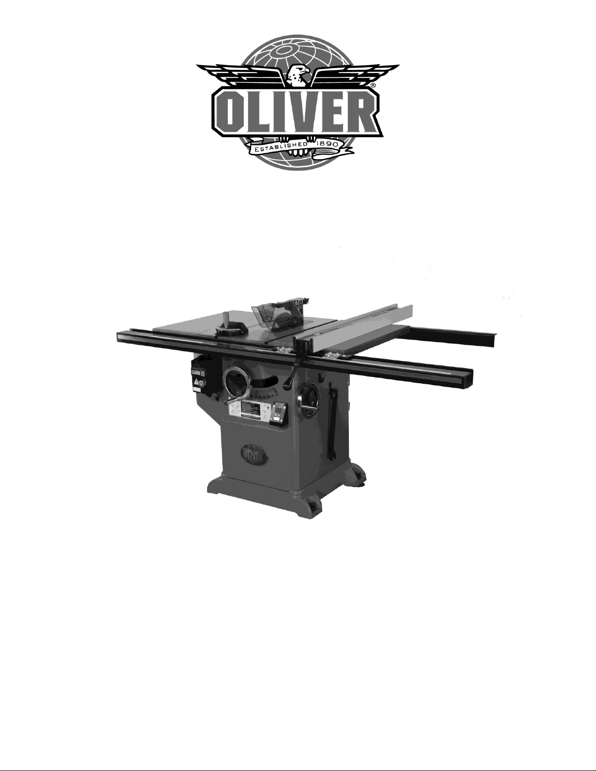
4045 12” Professional Tablesaw
Owner’s Manual
Oliver Machinery M-4045 04/2015
Page 2

2
Warranty
Oliver makes every effort possible to assure that its equipment meets the highest possible standards of
quality and durability. All products sold by Oliver are warranted to the original customer to be free from
defects for a period of 2 (two) years on all parts, excluding electronics and motors, which are warranted
for 1 year. Oliver’s obligation under this warranty shall be exclusively limited to repairing or replacing (at
Oliver’s option) products which are determined by Oliver to be defective upon delivery F.O.B. (return
freight paid by customer) to Oliver, and on inspection by Oliver. This warranty does not apply to defects
due, directly or indirectly, to misuse, abuse, negligence, accidents, unauthorized repairs, alterations, lack
of maintenance, acts of nature, or items that would normally be consumed or require replacement due to
normal wear. In no event shall Oliver be liable for death, personal or property injury, or damages arising
from the use of its products.
Warning
Read this manual thoroughly before operating the machine. Oliver Machinery disclaims any liability for
machines that have been altered or abused. Oliver Machinery reserves the right to effect at any time,
without prior notice, those alterations to parts, fittings, and accessory equipment which they may deem
necessary for any reason whatsoever.
For More Information
Oliver Machinery is always adding new Industrial Woodworking products to the line. For complete, up-todate product information, check with your local Oliver Machinery distributor, or visit
www.olivermachinery.net
The information contained in this publication has been prepared and obtained from original sources and data we
believe to be reliable, but we make no representations as to its accuracy, timeliness or completeness. Products
pictured may have slight differences during production and may have changed since the original publication of this
material. While every effort has been made to ensure the accuracy of the information it is subject to change without
notice.
Page 3

3
WARNING
Read this manual completely and observe all warning labels on the machine. Oliver Machinery has made
every attempt to provide a safe, reliable, easy-to-use piece of machinery. Safety, however, is ultimately
the responsibility of the individual machine operator. As with any piece of machinery, the operator must
exercise caution, patience, and common sense to safely run the machine. Before operating this product,
become familiar with the safety rules in the following sections.
Always keep guards in place and in proper operating condition.
Use blade guard for every applicable operation including all through cuts. If guard is removed
for special non-through cuts such as dado and rabbet cuts, replace before further use of the
saw.
Keep hands out of line with the saw blade.
Use a push stick.
Do not perform any operation freehand.
Never reach around or over the saw blade.
1. If you are not properly trained in the use of a tablesaw do not use until the proper training has been
obtained.
2. Read, understand and follow the safety instructions found in this manual. Know the limitations and
hazards associated with this machine.
3. Electrical grounding: Make certain that the machine frame is electrically grounded and that a
ground lead is included in the incoming electrical service. In cases where a cord and plug are used,
make certain that the grounding plug connects to a suitable ground. Follow the grounding procedure
indicated in the National Electrical Code.
4. Eye safety: Wear an approved safety shield, goggles, or glasses to protect eyes. Common
eyeglasses are only impact-resistant, they are not safety glasses.
5. Personal protection: Before operating the machine, remove tie, rings, watch and other jewelry and
roll up sleeves above the elbows. Remove all loose outer clothing and confine long hair. Protective
type footwear should be used. Where the noise exceeds the level of exposure allowed in Section
1910.95 of the OSHA Regulations, use hearing protective devices. Do not wear gloves.
6. Guards: Keep the machine guards in place for every operation for which they can be used. If any
guards are removed for maintenance, DO NOT OPERATE the machine until the guards are
reinstalled.
7. Work area: Keep the floor around the machine clean and free of scrap material, saw dust, oil and
other liquids to minimize the danger of tripping or slipping. Be sure the table is free of all scrap,
foreign material and tools before starting to use the machine. Make certain the work area is well
lighted and that a proper exhaust system is used to minimize dust. Use anti-skid floor strips on the
floor area where the operator normally stands and mark off machine work area. Provide adequate
work space around the machine.
8. Material condition: Do not attempt to saw boards with loose knots or with nails or other foreign
material. Do not attempt to saw twisted, warped, bowed stock.
9. Operator position: Maintain a balanced stance and keep your body under control at all times.
10. Before starting: Before turning on machine, remove all extra equipment such as keys, wrenches,
scraps, and cleaning rags away from the machine.
Page 4

4
11. Careless acts: Give the work you are doing your undivided attention. Looking around, carrying on a
conversation, and “horseplay” are careless acts that can result in serious injury.
12. Disconnect all power sources: Before performing any service, maintenance, adjustments or when
changing blades. A machine under repair should be RED TAGGED to show it should not be used
until the maintenance is complete.
13. Job completion: If the operator leaves the machine area for any reason, the tablesaw should be
turned "off" and the blade should come to a complete stop before their departure. The key should be
placed in the “off” position, removed and given to a supervisor to prevent any unauthorized use of the
tablesaw.
14. Replacement parts: Use only genuine Oliver Machinery factory authorized replacement parts and
accessories; otherwise the warranty and guarantee is null and void.
15. Misuse: Do not use this Oliver tablesaw for other than its intended use. If used for other purposes,
Oliver disclaims any real or implied warranty and holds itself harmless for any injury or damage which
may result from that use.
16. Drugs, alcohol and medication: Do not operate this machine while under the influence of drugs,
alcohol, or any medication.
17. This machine is deigned for cutting wood products only. Do not use to cut any kind of metal or
substance other then wood.
18. Never start the saw while a work piece is in contact with the blade.
19. Raise or lower the blade only when the machine has been turned “off” and the blade has come to a
complete stop.
20. Miter Gauge and Rip Fence: Never use the miter gauge and rip fence at the same time.
21. Damaged Saw Blade: Never use a damaged saw blade or one that has been dropped. Check the
saw blade for cracks or missing teeth. Do not use a cracked or dull blade or one with missing teeth.
Make sure the blade is securely locked on the arbor.
22. Make sure the blade is running in the proper direction. Refer to the arrow on the blade. The teeth
should be pointing down when viewing from the front of the saw.
23. Alignment: Check the alignment of the splitter to the blade. Also, check the alignment of the fence
to the miter slot.
24. Health hazards: Some dust created by power sanding, sawing, grinding, drilling and other
construction activities contains chemicals known to cause cancer, birth defects or other reproductive
harm. Some examples of these chemicals are:
Lead from lead-based paint.
Crystalline silica from bricks and cement and other masonry products.
Arsenic and chromium from chemically-treated lumber.
Your risk from these exposures varies, depending on how often you do this type of work. To reduce
your exposure to these chemicals, work in a well-ventilated area, and work with approved safety
equipment, such as those dust masks that are specifically designed to filter out microscopic particles.
Familiarize yourself with the following safety notices used in this manual:
CAUTION: (This means that if precautions are not heeded, it may result in minor or moderate injury
and/or possible machine damage)
WARNING: (This means that if precautions are not heeded, it could result in serious injury or possibly
even death).
Page 5

5
Table of Contents Page Number
Warranty ........................................................................................................................................................ 2
Warnings .................................................................................................................................................... 3-4
Table of Contents .......................................................................................................................................... 5
Specifications ................................................................................................................................................ 5
Contents of the Shipping Containers ............................................................................................................ 6
Machine Preparation and Setup ................................................................................................................... 7
Extension Wing Assembly ............................................................................................................................. 7
Handwheel Assembly .................................................................................................................................... 7
Rail Assembly ............................................................................................................................................... 8
Fence Assembly and Adjustment ................................................................................................................. 9
Adjusting the Scale Reader........................................................................................................................... 9
Calibrating the Digital Angle Readout ......................................................................................................... 10
Leveling Table Insert ................................................................................................................................... 11
Splitter and Blade Guard Assembly ............................................................................................................ 11
Miter Gauge ................................................................................................................................................ 12
Controls ....................................................................................................................................................... 12
Dust Collection ............................................................................................................................................ 12
Electrical Connections ................................................................................................................................. 13
Replacing the Blade .................................................................................................................................... 13
Maintenance ................................................................................................................................................ 14
Troubleshooting ..................................................................................................................................... 15-16
Specifications
Model Number ......................................................................................................................................... 4045
Blade Diameter (In) ..................................................................................................................................... 12
Arbor Diameter (In) .............................................................................................................. 5/8" (1” Optional)
Maximum Depth of Cut at 90 Degrees (In) .................................................................................................. 4"
Maximum Depth of Cut at 45 Degrees (In) ............................................................................................ 2-2/3"
Maximum Cut to the Right of Blade ........................................................................................................... 36”
Maximum Cut to the Left of Blade .............................................................................................................. 12”
Dust Port Diameter (In) ................................................................................................................................. 4
Table Dimensions w/Extensions (LxW) ............................................................................... 30-3/4” x 48-1/2"
Table Height (In) ........................................................................................................................................ 36”
Blade Tilt ................................................................................................................................................... Left
Arbor Speed RPM .................................................................................................................................. 3,450
Gross Weight ............................................................................................................................................ 803
Page 6
6
Oliver 4045, 12”Tablesaw
Contents of the Shipping Containers
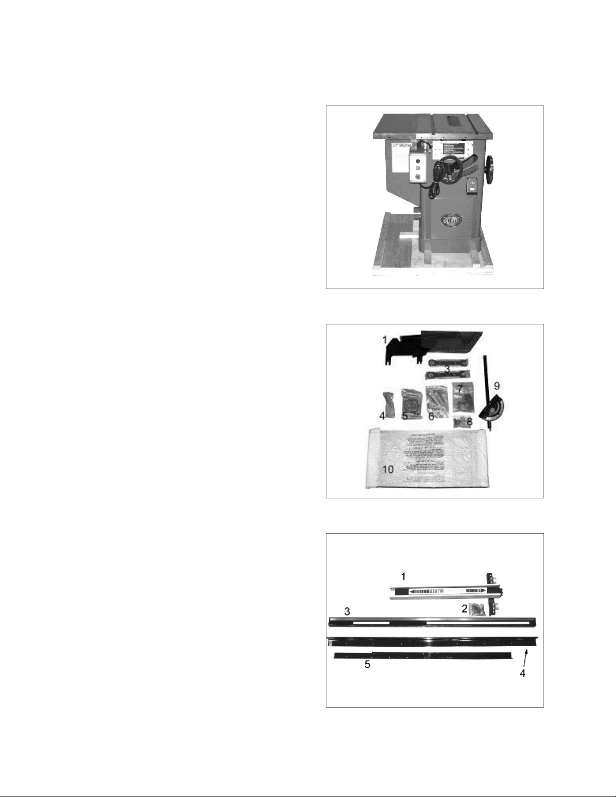
Saw
Once the top is removed the saw will be as
shown with the left extension wing already
attached. Inspect for freight damage and
call the freight carrier if any.
Contents
1. Blade guard
3. Arbor wrenches
4. Wheel handle
5. Accessory holders
6. Tools
7. Hardware packet, 5/8”
8. Extension wing hardware
9. Miter gage
10. Extension wing
Fence and Rail Assembly
1. Fence
2. Lock handle
3. Front guide
4. Front guide support bracket
5. Rear guide
Saw
Contents
Fence and Rail Assembly
Page 7
7
Machine Preparation and Setup
WARNING!
The equipment used to lift this machine must
have a rated capacity at, or above the weight
of the tablesaw. Failure to comply may
cause serious injury!
The tablesaw must be positioned on a smooth,
level surface. The area must be well lit and
have plenty of room to maneuver with large
pieces of wood.
Level the saw front to back and side to side
using a level placed on the table. Use shims
under the corners, if necessary, but make sure
the saw is stable before being placed into
service.
Clean all rust protected surfaces with a
commercial solvent. Do not use acetone,
gasoline, lacquer thinner or any type of
flammable solvent, or a cleaner that may
damage paint. Cover cleaned surfaces with
WD-40 or a 20W machine oil.
Pay particular attention to cleaning in the miter
slot and the faces of table and extension wing.
Extension Wing Assembly
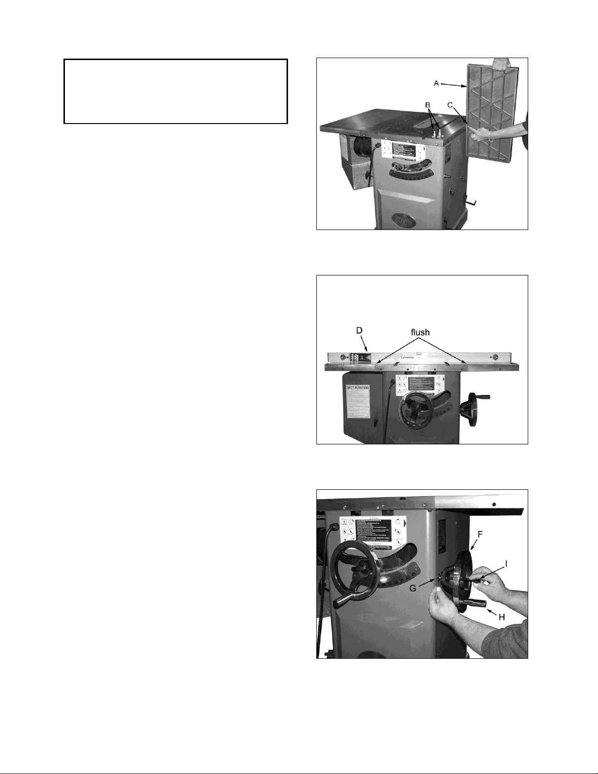
1. Attach extension wing (A, Figure 1) to table
with four hex head bolts, and four lock
washers (B, Figure 1). Snug but do not
tighten. Note: Start with one of the center
holes (C, Figure 1) to hold the wing in place.
2. Slide extension wing toward the front edge
of the saw table until two edges are flush.
3. Using a straight edge (D, Figure. 2), align
extension wing to saw table and tighten hex
cap bolts. Repeat for opposite wing.
Handwheel Assembly
1. Place handwheel (F, Figure 3) onto the saw
shaft. Use an allen key to lock the wheel
onto the shaft with the set screw (G, Figure
3). Insert and screw the locking handle (H,
Figure 3) and the wheel handle (I, Figure 3)
into their respective holes. Repeat for other.
Figure 1
Figure 2
Figure 3
Page 8
8
Rail Assembly
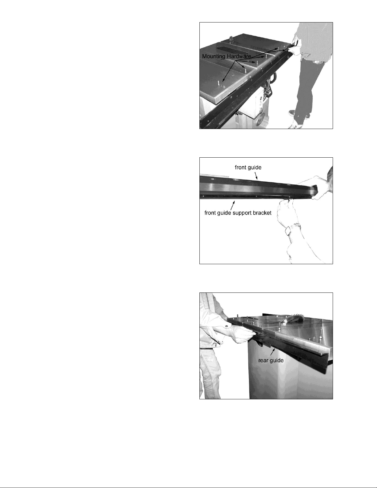
1. Rest the front guide support bracket on the
switch box as shown in Figure 4 and secure
into place using the chamfered bolts, nuts
and washers provided in hardware packet 7.
Note that the two outside holes require a nut
and washer as well as a bolt while the four
inside holes require the bolts only.
2. Set the front guide on the support bracket as
shown in Figure 5 and secure into place with
the short bolts provided in hardware packet
7.
Figure 4
Figure 5
3. Install the rear guide as shown in Figure 6
using the supplied hardware. Note that the
two outside holes require a nut and washer
as well as a bolt while the four inside holes
require the bolts and washers only.
Figure 6
Page 9
9
Fence Assembly and Adjustment
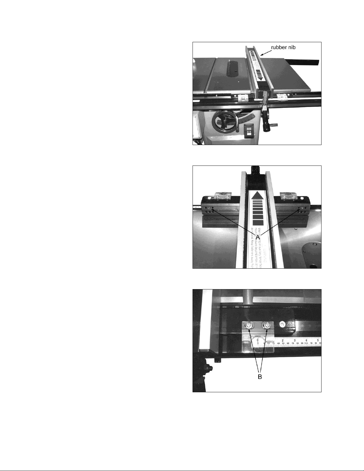
1. Place the fence on the guides as shown in
Figure 7. Look for the rubber nib on the
underside of the fence as shown and make
sure it lines up with the back support rail.
2. Align the fence with the miter guage slot as
shown in Figure 7 and check to see if the
fence is parallel to the slot.
3. If the fence is not parallel to the miter guage
slot, lift the fence off the guides and place it
on the table as shown in Figure 8. Turn the
appropriate screw, A to compensate for the
difference. Place the fence back on the
guides and check again for alignment to the
miter guage. If it is still mis-aligned, repeat
the procedure.
Adjusting the Scale Reader
1. Raise the blade to its maximum height.
Figure 7
2. Place the fence on the guides on the right
side of blade and then slide the fence
toward the blade. Continue until the fence
just touches the saw teeth. Do not push too
hard or the blade will deflect.
3. Looking at the right side scale reader, the
red pointer should match up with the zero
mark. If not, loosen the two screws, B,
Figure 9 and slide the viewer to align the
mark with zero. Tighten the screws.
4. Move the fence to the left side of the blade
and repeat the procedure for the left side
viewer.
Figure 8
Figure 9
Page 10
10
Calibrating the Digital Angle Readout
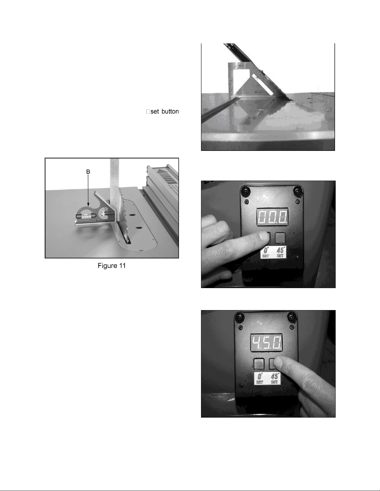
1. Place a square on the table as shown in
Figure 11 then turn the saw tilt wheel until the
blade comes to 90 degree.
2. Push and hold the 0 set button as shown in
Figure 14 until the display stops blinking. The 0
is now set.
3. Tilt the blade to 45 degrees as shown in
Figure 12. Push and hold the 45
as shown in Figure 15 until the display stops
blinking. At this point the angle display is
calibrated.
Figure 12
Figure 14
Figure 15
Page 11
11
Leveling Table Insert
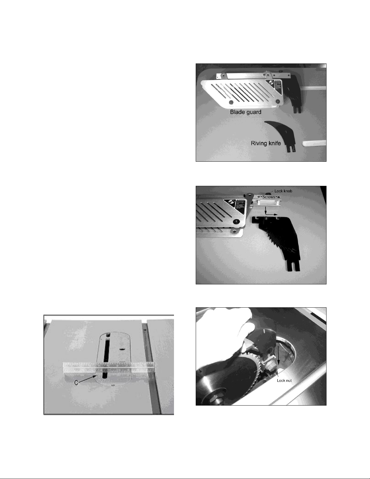
Adjust the table insert flush with the table by
turning the four leveling screws (C, Figure 16).
Place a straight edge across the table and
insert. Raise the insert until it just touches the
straight edge. Check both the front and rear
section of the insert.
Splitter and Blade Guard Assembly
The table saw comes equipped with both a
riving knife and blade guard (see Figure 17). It
is always recommended to use the blade guard
whenever possible. However, when doing
narrow cuts when the guard would interfere with
the fence or any other cuts in which the blade
guard would pose a problem, replace the guard
with the riving knife. Installation is the same for
both. For ease of installation, the blade guard
can be disassembled by loosening the lock knob
and separating the splitter from the guard as
shown in Figure 18. It may be necessary to
loosen the two screws as indicated in the
picture.
1. Disconnect saw from power source.
2. Remove table insert by loosening the screw
at the front of insert.
3. Loosen the lock nut then insert the fork of
the riving knife between the nut head and
backing plate as shown in Figure 19. Lock
into place.
4. Re-install the table insert.
Figure 17
Figure 18
Figure 19
Figure 16
Page 12
12
Miter Gauge
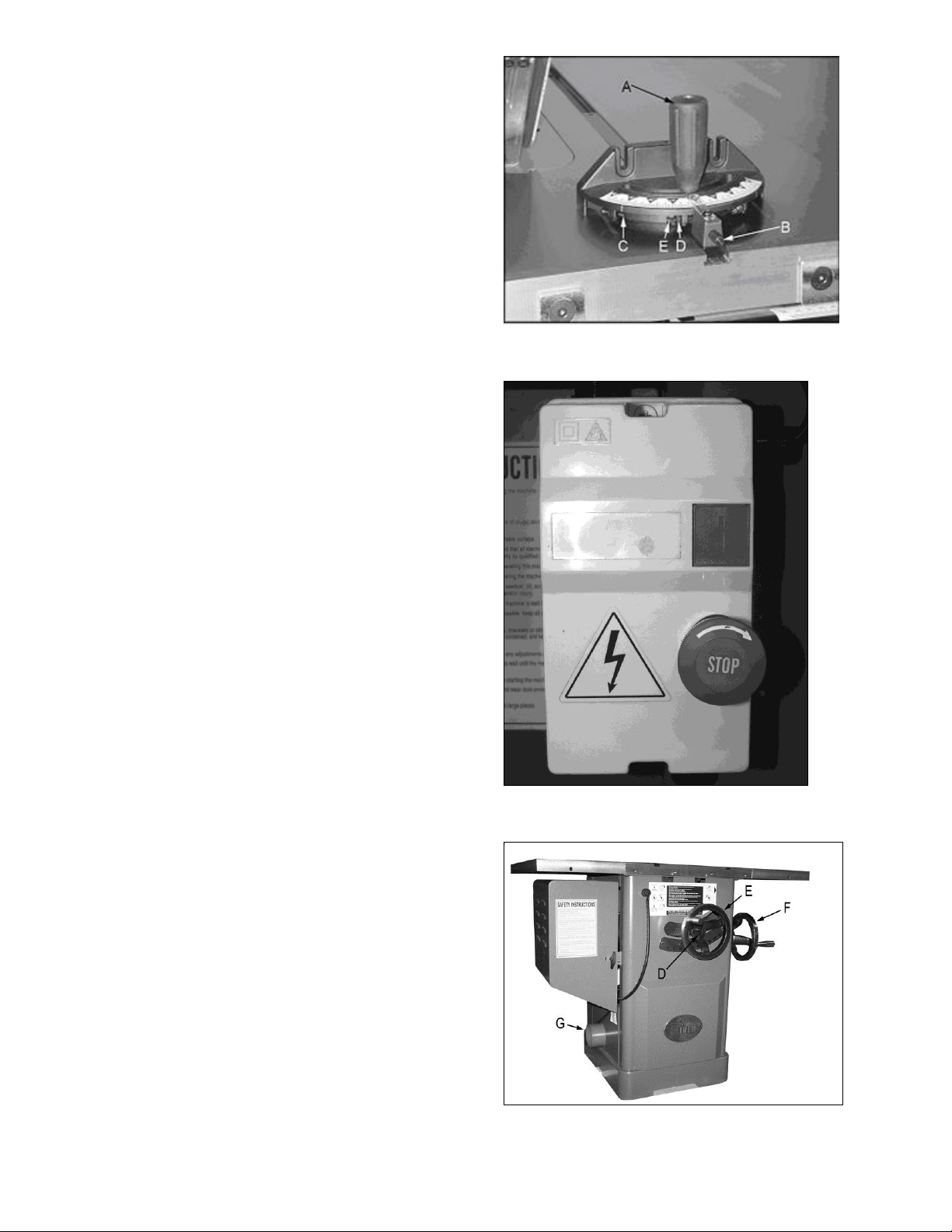
1. Slide the miter gauge bar into the miter
gauge slot in table. Loosen the handle (A,
Figure 23) and pull out indexing rod (B,
Figure 23) to pivot the miter gauge body.
2. Push the indexing rod in to engage the
preset stops (C, Figure 23).
3. Adjust stops by loosening the hex nut (D,
Figure 23) and adjusting screw (E, Figure
23).
Note: Always make test cuts. The scale is for
reference. There are two holes in the miter
gauge fence used to attach a wooden fence.
Controls (see Figures 24 & 25)
A. Emergency Stop Button: Stops all
functions of machine.
B. Start: Starts saw blade rotation. Will not
work if the “Emergency Stop” switch is
engaged, or the key is in the “OFF” position.
C. Handwheel Lock: There is a handwheel
lock on both handwheels. Loosen lock to
turn handwheel and tighten when blade is in
desired location.
D. Raising and Lowering Hand wheel:
Loosen hand wheel lock. Turn handle
clockwise to raise the blade. The blade
should be 1/8”-1/4” above the top of work
piece, or 3-5 blade teeth above the top of
work piece.
E. Tilting Hand wheel: Loosen hand wheel
lock. Turn handle counter-clockwise to tilt
blade to the left.
Dust Collection
There is a 4” dust port (G, Figure 25) located on
the side of saw cabinet. Make sure dust
collection system has sufficient capacity and
suction for your tablesaw. Always turn on dust
collection system before starting the tablesaw.
Figure 23
Figure 24
Figure 25
Page 13
13
Electrical Connections
WARNING!
Electrical connections and wiring must be
done by a qualified electrician. The machine
must be properly grounded. Failure to
comply may cause serious injury!
This saw is available in both 1-Phase and 3Phase versions.
Electrical Connections for a 3-Phase Unit
This saw is 3-Phase, 220V/440V pre-wired
220V. If you need to switch the tablesaw from
220V to 440V have a qualified electrician make
the changes. Oliver Machinery recommends
using a dedicated circuit.
Make sure the voltage of your power supply
matches the specifications on the motor plate of
the machine.
With 3-Phase power verify the blade is turning in
the proper direction. Turn the saw on and make
sure the direction of the blade spins toward the
user when standing in front of the saw. If it does
not, disconnect the power source and reverse
any two power leads.
Electrical Connections for a 1-Phase Unit
This saw is 1-Phase, 220V only. Oliver
Machinery recommends using a dedicated
circuit.
Make sure the voltage of your power supply
matches the specifications on the motor plate of
the machine.
Replacing the Blade
The blade guard has been removed for photos,
but it is possible to change the blade without
removing the blade guard.
1. Disconnect saw from power source.
2. Remove the table insert and raise the blade
completely.
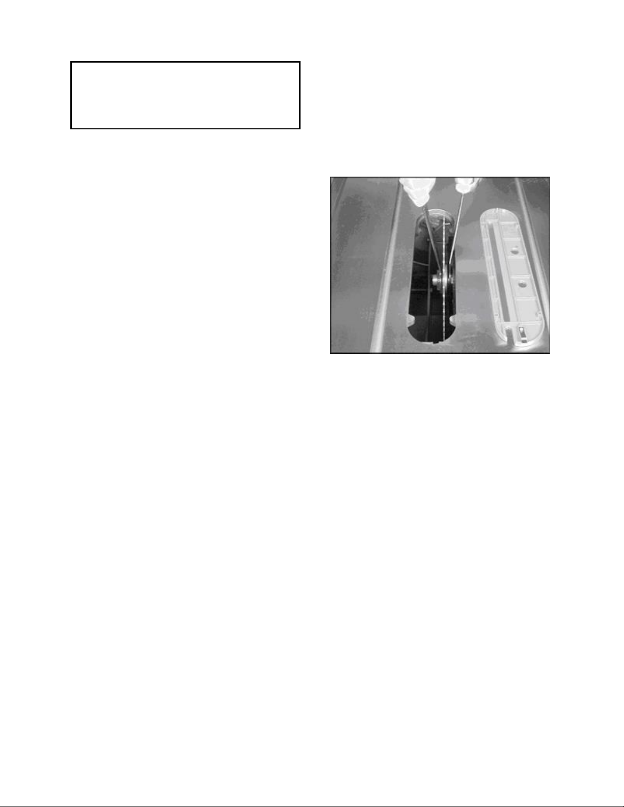
3. Use the two provided arbor wrenches to
loosen the arbor nut, as shown in Figure 25.
Place one wrench on the arbor nut and one
on the flats located on the arbor. Remove
the nut, flange and blade.
4. Replace the blade followed by the flange
and arbor nut. Tighten the arbor nut while
holding the arbor in place.
Note: Make sure the blade and arbor are clean
before installing a new blade. The blade teeth
should point down when viewing from the front
of saw.
Figure 25
Page 14
14
Maintenance
WARNING!
Disconnect the machine from power source
before proceeding with any maintenance, or
troubleshooting! Failure to comply may
cause serious injury!
Periodically clean the inside of the machine for
dust control. Use an air hose to blow out dust
from motor fan and motor cover.
Use a wire brush to clean trunnions and worm
gears. Apply white lithium grease or powdered
graphite to lubricate worm gears, and trunnions.
Keep pulleys and belts free from dirt, dust, oil
and grease.
Replace worn v-belts as needed.
Remove rust from the tabletop with WD-40 and
a Scotch-Brite™ Hand Pad. Keep a light coat of
WD-40on the table top when not in use
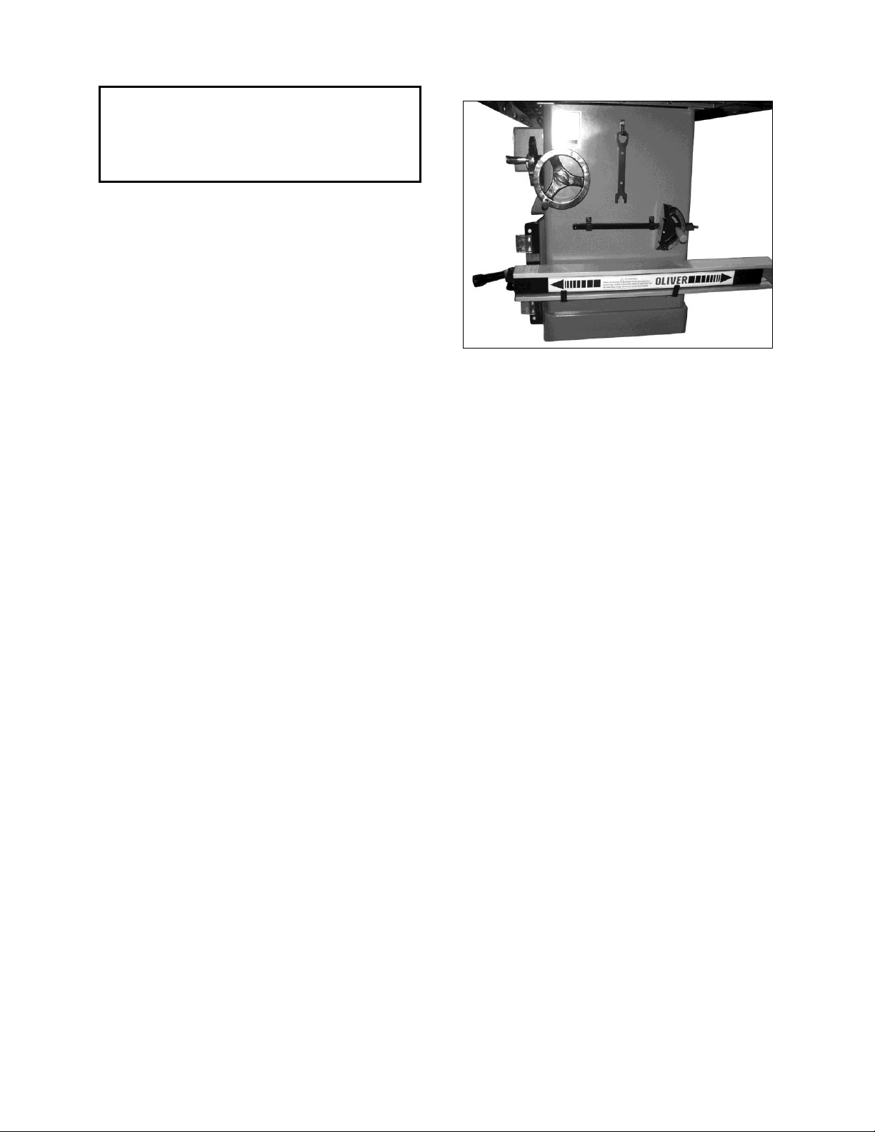
Accessory Holders
Figure 27
See Figure 27 for the correct placement of
the accessory holders.
Page 15

15
Description of Symptoms
Possible Cause
Corrective Action
Machine will not start
1. Fuse blown or circuit breaker
tripped
2. Cord Damaged
3. Faulty switch
4. Not connected to power
source
5. Connected to wrong voltage
6. Key in the “OFF” position
7. Emergency stop button
pressed
1. Replace fuse or reset circuit
breaker
2. Have cord replaced
3. Replace switch
4. Check connection
5. Check voltage
6. Insert key and turn to “ON”
position
7. Rotate emergency stop button
clockwise until it pops out
Blade does not come up to speed
1. Cable too light or too long
2. Low current
3. Motor not wired for correct
voltage
1. Replace with adequate size
cable
2. Contact local electric
company
3. Refer to motor nameplate for
correct voltage
Does not make accurate 45° or
90° cuts
1. Stops not adjusted correctly
2. Angle pointer not set
accurately
3. Miter gauge out of adjustment
1. Check blade with combination
square and adjust stops
2. Check blade with combination
square and adjust pointer
3. Adjust miter gauge
Saw makes unsatisfactory cuts
1. Dull blade
2. Blade mounted backwards
3. Gum or pitch on blade
4. Incorrect blade for cut
1. Sharpen or replace blade
2. Turn blade around
3. Remove blade and clean
4. Change blade to correct type
Material binds blade when ripping
1. Fence not aligned with blade
2. Warped wood
3. Excessive feed rate
4. Splitter not aligned with blade
1. Check and adjust fence
2. Select another piece of wood
3. Reduce feed rate
4. Align splitter with blade
Troubleshooting
.
Page 16

16
Saw vibrates excessively
1. Stand on uneven floor
2. Damaged saw blade
3. Bad V-belts
4. Bent pulley
5. Improper motor mounting
6. Loose hardware
1. Reposition on flat, level
surface
2. Replace saw blade
3. Replace V-belts
4. Replace pulley
5. Check and adjust motor
6. Tighten hardware
Material kicked back from blade
1. Rip fence out of alignment
2. Splitter not aligned with blade
3. Feeding stock without rip
fence
4. Splitter not in place
5. Dull blade
6. Letting go of material before it
is past blade
7. Anti-kick back paws dull
1. Align rip fence with miter slot
2. Align splitter with blade
3. Install and use rip fence
4. Install and use splitter (with
guard)
5. Replace blade
6. Push material all the way past
blade before releasing work
7. Replace or sharpen anti-kick
back paws
Blade does not raise or tilt freely
Sawdust and debris in raising
and tilting mechanisms
Clean and regrease
Page 17
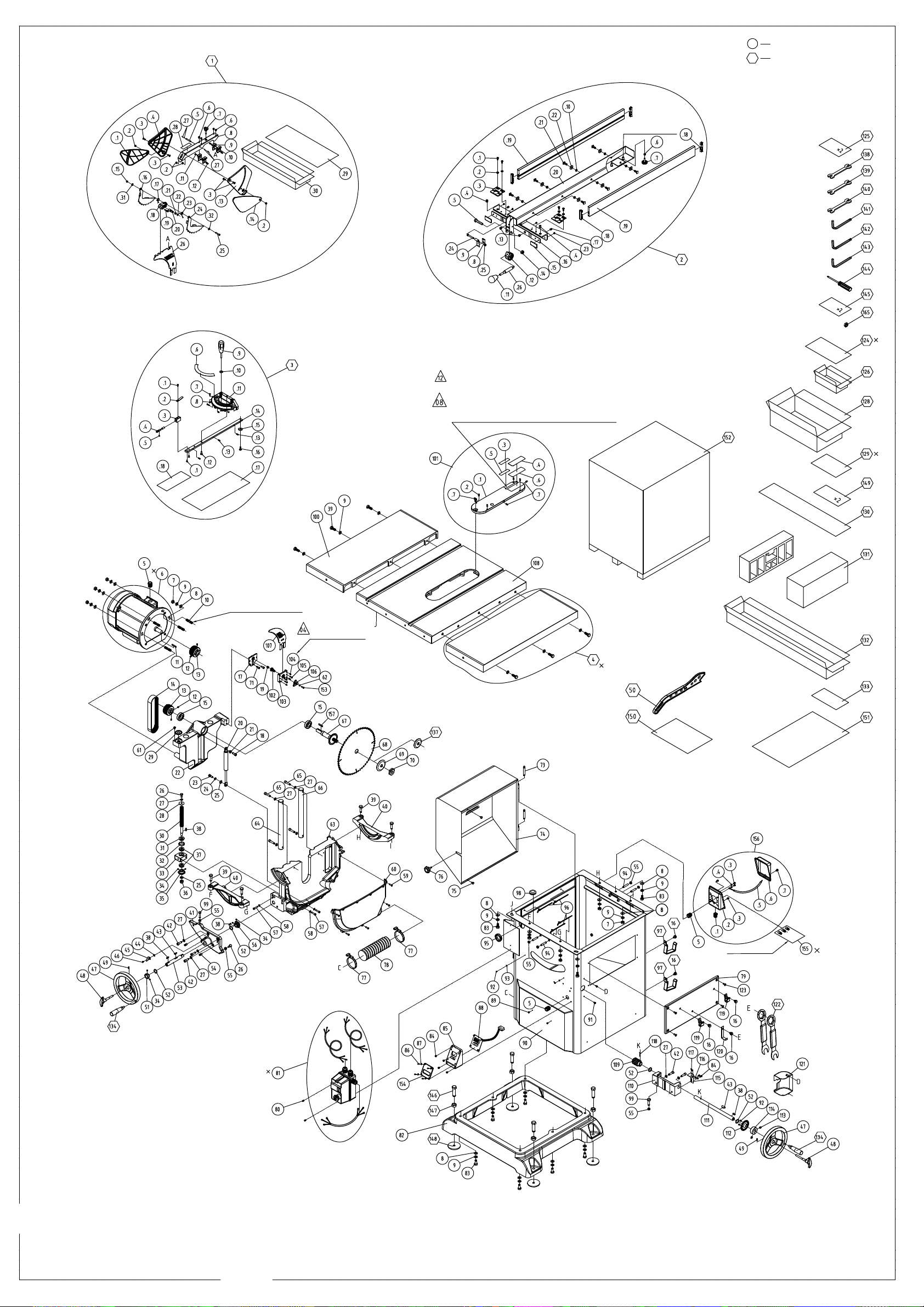
Clean and remove grease from plates
before applying to blade inserts.
Apply 3M-94 primer glue to the pads
2 hours prior to sticking to the blade inserts.
Apply Locktite #638
before inserting screws.
Use green Locktite
on set screws.
Bag for push blocks.
Machine anti-dust bag.
Bagged hardware inside of wiring box.
Assembled with machine.
Not assembled with machine.
4045
MFG after 2011/3
Page 18

!4045!Parts!List
Index Part!Number Description Specification Qty Old!P/N Notes
! "#$%&%'%%% ()*+,-+*./0012 34%56%7 ! "##58%'%%% !%%!#77
6! #&%7#!'8#% 9+:;.<=,*-.>?,*- !
6# %%7$%#'#%% 9?@A.(@*+B C&D%67EF7>D8GH I
6$ %%%I%#'#%5 JK,;.G+,-.(@*+B C&D%67ED!& I
6I #&%7#I'8#% 9+:;.<=,*- !
6& $8%"8#'"%! ELM !
68 %%%$%$'!%! N?=M-.G+,-.EOLK.(@*+B C&D%67ED8 I G/%I%8%#
65 #$%$$8'8!& >?K; !
67 !5!I&#'"%I >?K;.>K?@A !
6" !$%#5%'"%$ >*,@A+; #
6!% !$%#5!'"%$ >*,@A+; #
6!! %%%$%#'!%$ N?=M-.G+,-.EOLK.(@*+B CID%65ED!% # G/%I%I%I
6!# $8%"8%'"%! ELM #
6!$ #&%7#$'8#% NLPO;.<=,*-.>?,*- !
6!I #&%7!"'8#% NLPO;.<=,*-.. !
6!5 #7%!8#'"%! ()*LMP.FNLPO;H ! 3G#&%%I"
6!" $8%78I'%%% ELM ! 3G#&%%&!
6#% $8%78&'"%! ()*+,-+*.(O,:; ! 3G#&%%I5
6#! #7%!8%'"%! ()*LMP ! 3G#&%%I7
6## %!%#%I'%%% S'NLMP S3T'5 ! GJ%$!8%%
6#$ #7%!8$'"%! ()*LMP.F9+:;H ! 3G#&%%&%
6#& %%%$%$'!!% N?=M-.G+,-.EOLK.(@*+B C&D%67ED$% ! !%%!#77
6#8 !5!I$7'"%I ()*+,-+*.. !
6#5 %I$$#$'%%% U'NVQ<.FE.32)+H E$ I
6#7 &5$&I$'%%% T,*MLMP.9,W+K !
6#" %I!$%$'%!& EK,0;L@.>,P &$%D$$%FU)+MHD%6%&; ! GN%#88%%
6$% &#%%%!'8%& ()*+,-+*.>?X I7%D5%D#!8YY !
6$! %%8%%!'%!# JK,;.T,0O+* &6$D!#D!6%; # !%%!#77
# "#!&&5'%%% J+M@+./00+YWK2 ! N34%$%#
6! %%%$%I'#%$ N?=M-.G+,-.EOLK.(@*+B C8D!6%ED!# I G(%I%5%&
6# %%8%%#'%#$ JK,;.T,0O+* 86$D!$D#6%; I GZ!!%!%%
6$ #&%I5%'8#% VM-L@,;?* # 3G!#%5%&
6I #&%I5#'8#! EK,0;L@.(+;.(@*+B C!#D!65&E # 3G!#%5%$
6& %%%%%I'$%8 G+X6.(@*+B C!%D!6&ED&% ! G/%!%8#7
68 %%7%%&'!%% G+X6.Q=; C8D!6%EF!%>D&GH ! G[%!%8%%
65 #&%&75'8!& (KL-LMP.RM?W !
67 #&%8%#'8#! EK,;+ !
6" !5!""$'"%I >*,@A+; !
6!% %%7%%8'!%% G+X6.Q=; C7D!6#&EF!$>D86&GH 7 G[%!%7%%
6!! #$%#7#'8!& RM?W ! 34%$%%I"
Page 19

!4045!Parts!List
Index Part!Number Description Specification Qty Old!P/N Notes
6!#
"##!I!'%%%
[,Y./00+YWK2 !
!$%#$&'"%$ [,Y... !
88%%%#'%%% C,PM+; # EG%!%8%#
6!$ %%#!%$'!%$ JK,;.G+,-.(@*+B C8D!6%ED7 #
6!& #&%I5!'8#! EK,;+ # 3G!#%5%#
6!8 !5!$5#'"%I EK,;+.E?0L;L?MLMP.>*,@A+; 電著電著F黑 ! 3G!#%5%I
6!5 %%!"%$'!%& (S3.9?@A.(@*+B C7D!6#&ED7 # G/$#%&%$
6!7 #&%I7$'8!& [,) I N3G!8%#%$
6!" $!%%7$'"%" (L-+.>?,*- # N3G!8%#%#
6#% !5!I#$'$%7 J+M@+.>?-2 ! N3G!8%#%!
6#! %I75%!'!%! (\=,*+.G+,-.(@*+B C7D!6#&ED#% 7 3 G%&%%#$
6## %%8%%!'%I" JK,;.T,0O+* 76&D!8D#6%; 7 GS%!$8%%
6#$ #&%85#'8!& E,@ALMP I !$%I!7"
6#I %%%%%#'$%7 G+X6.(@*+B C8D!6%EDI& !
6#8 $7%77$'"%I RM?W.(O,:; ! 34%$%%I7
$ "#!57#'%%% CL;+*.<,=P+./00+YWK2 ! N34%I%&
6! %%$$%$'!%& N?=M-.G+,-.EOLK.(@*+B $]!8^'#IQ[D$]7^. $ G>%I%"%&
6# #&%!"$'8#% VM-L@,;?* ! 3G%!%$%I
6$ !$%%&$'"%$ >K?@A ! 3G%!%$%& !I%!II!
6I $8%$7!'"%! (O,:; ! 3G!#%8%8
6& %I$$!!'%%% U'NVQ<.FE.32)+H E& ! GC%7%$%%
68 &5!!&!'%%% (@,K+ ! 3G%!%$%$
65 %%$$%&'!%8 N?=M-.G+,-.EOLK.(@*+B &]$#^'$#Q[D&]7^ $ G>%I%7%5
67 %%"%%!'!%% G+X6.Q=; &]$#^'$#Q[F7>D$67GH $ G_%!%#%%
6" #&%!I8'%%% G,M-K+ ! 3G%$%$%!
6!% %%8%%#'%&! JK,;.T,0O+* 76&D!7D$; ! GZ%!$5%%
6!! %"%%85'%%7 CL;+*.<,=P+.. ! 3G%!%$%#
6!# #"%%!5'"%! (@*+B ! 3G%!%$%7
6!$ #$%###'"%! N?=M-.>,KK.(+;.(@*+B $ 3G!#%8%# !#%!I$5
6!I $7%8!I'"%I >,* ! N34%$%%I!
6!& $7%%8"'"%! <=L-+.E,@ALMP ! 3G%$%$%$
6!8 %%%I%$'!%& JK,;.G+,-.(@*+B C8D!6%ED8 ! G/%&%I%#
6!5 %I!$%$'%!" EK,0;L@.>,P 5%%D#7%FU)+MHD%6%&; ! GN%#&8%%
6!7 %I!!%#'%%$ EK,0;L@.>,P !8&D7%FU)+MHD%6%&; ! GN%#%I%%
DI 34%7'7$ SX;+M0L?M.TLMP 34#`
& %#!$%8'%%% (;*,LM.N+KL+: .E</!8'!I>FBL;O.,.Q=;H $ GE%I#8%% !%%!%"5
D8 34%7'%! C?;?* 34%/
5 %%7%%5'!%% G+X6.Q=; C!%D!6&EF!5>D7GH 7 G[%!!%%%
7 %%8%%!'%8" JK,;.T,0O+* !%D#%D$6%; !5 G/%I%5%&
" %%8$%5'!%% ()*LMP.T,0O+* !%6#D!76& #% GS%#!$%%
!% $8%58!'"%! >?K; I N34%$%%#!
!! %!#%%$'%!$ R+2 &D&DI% ! GG%!%I#$
Page 20

!4045!Parts!List
Index Part!Number Description Specification Qty Old!P/N Notes
!# %%!"%#'!%# (S3.9?@A.(@*+B C8D!6%ED7 I G/$#%I%$
!$ $7%77#'"%# E=KK+2 # 34%5%%%5
!I %!I$$$'%%%
>+K;
##%'4!# !
!& %$%#%!'%%# >,KK.>+,*LMP 8%%& # !!%!$$&
!8 %I"#%!'!%# G+X6.(@*+B.B]JK,;.T,0O+* C7D!6#&ED!#]F!$>D86&GH $
!5 !$%#8"'"%$ >*,@A+; ! %"%!$!5
!7 %%%!%I'!%8 [/E.(@*+B C7D!6#&ED#% ! G/%#%&!% !#%!$I%
!" #7%!78'"%! ()*LMP ! %"%!$!5
#% 88%!I5'%%% [2KLM-+* ! 34%5%%!8
#! !8%%58'%%% >=0OLMP ! 3G#5%%#%
## %&%"I"'%%% a)]_?BM.>*,@A+; ! 34%5%%%$
#$ #"%%$$'"%! (@*+B ! ER%!%%$"
#I %%85%$'!%% T,0O+* TT'!% ! GS%5%&%%
#& %%8%%!'%55 JK,;.T,0O+* !%6&D!"D!6%; # GS%!&"%%
#8 %%%%%$'!%I G+X6.(@*+B C7D!6#&ED#% # G/%!%&!%
#5 %%8$%&'!%% ()*LMP.T,0O+* 76#D!&6I !% GS%#!!%%
#7 %%8%%!'%I% JK,;.T,0O+* 7D$%D$6%; !
GS%!7$%%
#"
88%!8%'%%%
>*=0O ! 34%5%%##
$% $8%75&'"%! a)]_?BM.T?*Y.(O,:; ! 34%5%%!!
$! !8%%5$'%%% >=0OLMP ! 3G#&%%8#
$# 88%!II'%%% /M;L._=0;.NLMP ! 3G#5%%!%
$$ !$%#$5'"%$ >*,@A+; !
3G#5%%#"
$I %%!"%!'!%! (+;.9?@A.(@*+B C&D%67ED& 8 G/$#%$%!
$& $7%585'%%% >+b+K.<+,* 9+:;.3O*+,- ! !$%!$!'%%%
$5 %$!%%&'%%! 3O*=0;.>+,*LMP &!!%# # !!%!$$&
$7 %!#%%$'%%8 R+2 &D&D!7 I GG%!%I!% !&%!%$#
$" %%%%%I'!%I G+X6.(@*+B C!%D!6&ED$& 5 G/%!%8!"
I% %&%&8!'%%% >*,@A+;.FN+,*H # 34%#%%%#
I! %&%"&%'%%% >*,@A+; ! 34%5%%!%
I# %%%!%I'!%7 [/E.(@*+B C7D!6#&ED#& &
G/%#%&!&
I$ !$%%8!'%%% R+2 # 34%!%%I!
II %%8&%$'!%% T,0O+*.B]3++;O 86ID!!F>T'8H ! GS%I%"%%
I& !5!8"5'!&8 VM-L@,;?* ! 34%#%%!I
I8 %%%$%I'!%$ N?=M-.G+,-.EOLK.(@*+B C8D!6%ED!# ! G/%I%5%&
I5 #I%%I"'%%% G,M-.TO++K # 3G!#%%8&
I7 "#%88#'%%% 9?@A.>?K;./00+YWK2 # 34%!%$
$8%%$8'%%% 9?@A.>?K;./00+YWK2 ! 34%!%$%!
I" %%!"%#'!%& (S3.9?@A.(@*+B C8D!6%ED!# #
&% E=0O.(;L@A
&! !$%##7'"%$ NLMP !
&# %%8%%8'!%8 JK,;.T,0O+* !"6!D#&6ID!68 I 3G!#%%7!
&$ $8%75I'"%! a)]_?BM.(O,:; ! 34%5%%!$
Page 21

!4045!Parts!List
Index Part!Number Description Specification Qty Old!P/N Notes
&I $8%$&&'"%!
ELM
# E4%!%%II
&& %%7%%8'!%% G+X6.Q=; C7D!6#&EF!$>D86&GH 5 G[%!%7%%
&8 $7%587'%%% >+b+K.<+,* NLPO;.3O*+,- ! !$%!$!'%%%
&5 %%%!%$'!%7 [/E.(@*+B C8D!6%ED#& $ G/%#%I!$
&7 %%8$%$'!%% ()*LMP.T,0O+* 86!D!#6$ $ GS%#%"%%
&"
%%%$%$'#%5
N?=M-.G+,-.EOLK.(@*+B C&D%67ED#% & G(%I%8!%
8%
#&%5!!'8!&
(L-+.[?b+* ! 34%5%%%#
8! %%!8%#'!%! N?=M-.G+,-.B]JK,;.T,0O+* C&D%67ED!%]&D!#D%67; ! G/#8%I%%
8# %%8$%#'!%% ()*LMP.T,0O+* &6!D"6$ ! GS%#%7%% %"%!$!5
8$ %&%8#"'%%% 3*=MML?M ! 34%5%%%!
8I $8%75#'%%% [?K=YM ! 34%5%%%&
8& %%%!%I'!!# [/E.(@*+B C7D!6#&EDI% I G/%#%&##
88 $8%75$'%%% [?K=YM ! 34%5%%%8
85 $7!%!!'"%! &]7^./*W?* ! !%%!!%!
87 $"%%!!'%%% >K,-+ ! 34%!%%8$
8" $7!%!#'"%! &]7^.>K,-+./-,);+*.T,0O+* J?*.!^./*W?*.>K,-+./-,);L?M ! !%%!!%!
5% $7%%&#'"%! &]7^.>K,-+./-,);+*.Q=; ! 34%!%%5& !%%!!%!
5! %%%!%I'!%I [/E.(@*+B C7D!6#&ED!8 # G/%#%&%7 !#%!$I%
5# %%%!%$'!!I [/E.(@*+B C8D!6%ED8% ! G/%#%I$I
5$ #$%!"8'"%7 >?K; # N34%$%%#"
5I !5#%#8'%%% (OL+K- ! N34%$%%!"
5& $I%%%5'8!& E,@ALMP # E<%!%%I8
58 #$%!$!'%%% >?K; ! ((%!!#55
55 %I#8%7'%%% [K,Y) c8%'7%YYFLMM+*.-L,Y+;+*H #
57
%I#8%!'%%%
G?0+ #6&dFLMM+*.-L,Y+;+*HD!%%%YY !
5"
!5##88'%%%
[?b+*.EK,;+.FNLPO;H !
7% %%$$%$'!%! N?=M-.G+,-.EOLK.(@*+B $]!8^'#IQ[D!]#^ # G>%I%"%8
D7! 34%7'%# (BL;@O.>?X./00+YWK2 34%>
7# %&%7##'%%% [,0;.V*?M._,Y)LMP.>,0+ ! N34%I%%%I
7$ %%%%%I'!%# G+X6.(@*+B C!%D!6&ED#& " G/%!%8!$
7I %%%$%$'#%# N?=M-.G+,-.EOLK.(@*+B C&D%67ED7 8
7& #&%&I5'8!& (+M0?*.>?X !
78
%%%$%!'#%#
N?=M-.G+,-.EOLK.(@*+B C$D%6&ED!# I !%%!%"5
75 %%8%%#'!$" JK,;.T,0O+* $D7D!6%; I
77 "&%#"&'%%% (+M0?*./00+YWK2 ##%eI8%`FBL*+.K+MP;O.I&%YYH ! I"%I#!'%%%
7" %%%I%!'!%I JK,;.G+,-.(@*+B CID%65ED!% # G/%&%#%I
"% !5#&"8'%%% C,@OLM+.>?-2 ! 34%7%%%!
"! %%!!%#'8%I N?=M-.G+,-.(+K:.3,))LMP.(@*+B CID!6&"ED!# # G(!7%$%&
"# %%%$%#'!%! N?=M-.G+,-.EOLK.(@*+B CID%65ED8 I G/%I%I%#
"$ %%8%%!'%%! JK,;.T,0O+* I6$D!%D!6%; # GS%!%8%%
"I %%!"%$'!%5 (S3.9?@A.(@*+B C7D!6#&ED&% I G/%$%
"& %#!7%8'%%% NLMP (>'$7 ! GE#%%8%% !%%!%"5
"8 #$%#"5'8!& [O,LM I 3G!%%%7!
"7 %#!&%5'%%% !
Page 22

!4045!Parts!List
Index Part!Number Description Specification Qty Old!P/N Notes
"" %%%%%$'!%5 G+X6.(@*+B C7D!6#&ED$& # G/%!%&!"
!%% %&%57&'%%7 SX;+M0L?M.TLMP ! N34%$%%I%
!%! "##55#'%%% >K,-+.VM0+*;./00+YWK2 34%56%7 ! %"%!$!5
6! #&%7#5'8!& >K,-+.VM0+*;... !
6# #&%7##'8!8 >?K; !
6$ #5%%8#'"%# EK,;+.F9+:;H !
6I #5%%8$'"%# EK,;+.FNLPO;H !
6& I#%%!8'%%% 3,)+.F9+:;H $C.I87CEF!"YYH !
68 I#%%!5'%%% 3,)+.FNLPO;H $C.I87CEF$&YYH !
65 %%!"%#'!%& (S3.9?@A.(@*+B C8D!6%ED!# 8
!%# $7%"77'"%! 9?@A.>?K;.. ! %"%!$!5
!%$ !$%#87'"%$ >*,@A+; ! %"%!$!5
!%I %%!"%#'!!% (S3.9?@A.(@*+B C8D!6%ED7 I !%%!%II
!%& %%%7%I'!%8 N?=M-.G+,-.G+X.(@*+B C&D%67ED!8 # G/%"%$%7 %"%!$!5
!%8 %"%#II'"#% RM?W ! %"%!$!5
!%5 !5!&58'"%I NLbLMP.RML:+ ! %"%!$!5
!%7 %&%57I'%%7 3,WK+ ! N34%$%%$"
!%" $#%$7!'"%! T?*Y.(O,:; ! 34%#%%!! %"!7%!I
!!%
%&%&7#'%%7
>*,@A+; ! US$#%%%$
!!!
$8%7%5'"%!
(O,:; !
!!# !5#!!%'%%% EK,;+ ! 3G#I%%%&
!!$ %%!"%$'!%I (S3.9?@A.(@*+B C7D!6#&ED!% # G/$#%&%I
!!I
!$%%$!'%%%
NLMP ! N34%$%%I5
!!&
!5%#8#'%%%
9.(O,)+.EK,;+ !
!!8 %%8%%!'%%" JK,;.T,0O+* &6#D!%D!6%; # GS%!!!%%
!!5 %%!!%!'#%& N?=M-.G+,-.(+K:.3,))LMP.(@*+B C$D!6%8ED8 #
!!7 %!!%%$'!%8 ELM &D#7 ! G<%!!%!8
!!" !5%&I#'"%I G??A.N,@A # 3G%#%%#&
!#% !5%"8&'"%I N,@A ! 34%!%%"%
!#! #&%8$#'8!& [?b+*.. ! N34%$%%I8
!## !5#%$$'"%I T*+M@O # N34%$%%$5
!#$ %%%I%$'!%I JK,;.G+,-.(@*+B C8D!6%ED#% I G/%&%I!%
D!#I 34%7'!I C,M=,K 34%Q
!#8 &#%%%!'&&$ G,*-B,*+.>?X I7%D!#%D8%YY ! %"%!$!5
!#7 &#%%%!'&&& >?X I"&D#%%D#$&YY ! %"%!$!5
D!#" 34%7'!% C,@OLM+.3,P 34!/
!$% %I!$%&'%#" EK,0;L@.>,P !#"%D8#%F?)+MHD%6!; ! !$!"%%!
!$! "I7%8!'%%% (;2*?:?,Y.:?*.N,LK./00+YWK2 !
&%%%&8'!%% (;2*?:?,Y.:?*.J*?M;.N,LK !
&%%%&8'#%% (;2*?:?,Y.:?*.N+,*.N,LK !
!$# &#%%%"'%#$ >?X.:?*.N,LK0 !!#%DI8%D#!%YY !
!$$ %I!!%#'%!% EK,0;L@.>,P I7%D7%F?)+MHD%6%&; ! GN%##I%%
!I& %I!$%&'%%I EK,0;L@.>,P #5&D!"&F?)+MHD%6!; ! GN%II7%% !#!"%%5
!I" %I!$%8'%%# EK,0;L@.>,P !"%D!$%F?)+MHD%6!&; ! !$!"%%8
Page 23
!4045!Parts!List
Index Part!Number Description Specification Qty Old!P/N Notes
!&! %I!5%#'%%$ EK,0;L@.>,P !8%%D!7%%F?)+MHD%6!; ! !!%!#%"
!&# 8!%%%$'%7& T??-+M.[*,;+ !!!%D78%D!%"%YY ! 34%7%%%# !$%!#5$
!&$ %%#&%$'!%! N?=M-.G+,-.G+X.9?@A.(@*+B C&D%67ED!# ! %"%!$!5
!&I #&%7$"'8#% N+,-?=;.[K+,*.E,M+K ! !%%!%"5
D!&& 34%7'7& G,*-B,*+.>,P ((#G !%%!%"5
!&8 "##7"&'%%% TL*LMP./00+YWK2 ! !%%!%"5
6! %#!$%8'%%% (;*,LM.N+KL+: E</!8'!I>FBL;O.,.M=;H ! GE%I#8%%
6# I"%8%"'%%7 J*?M;.[?b+* !
6$
%%%$%$'!%$
N?=M-.G+,-.EOLK.(@*+B C&D%67ED!% I G/%I%8%I
6I %%8&%#'!%% U=;;+*.3??;O+-.T,0O+* &D!%D%68;fF>T'&H # GS%I%7%%
6& I5!%%I'%!# [?MM+;LMP.[(/.TL*+ (43!#/T<D![D!&%YY.F<*++MH !
68 I"%!#I'%%7 N+,*.[?b+* ! EQ%!%7%!
65 %%$$%$'!%# N?=M-.G+,-.EOLK.(@*+B $]!8^'#IQ[D!]I^ ! G>%I%"%$
!&5 %!#%%$'%!! R+2 &D&D$& ! GG%!%I#% !&%!%$#
 Loading...