

Page 1
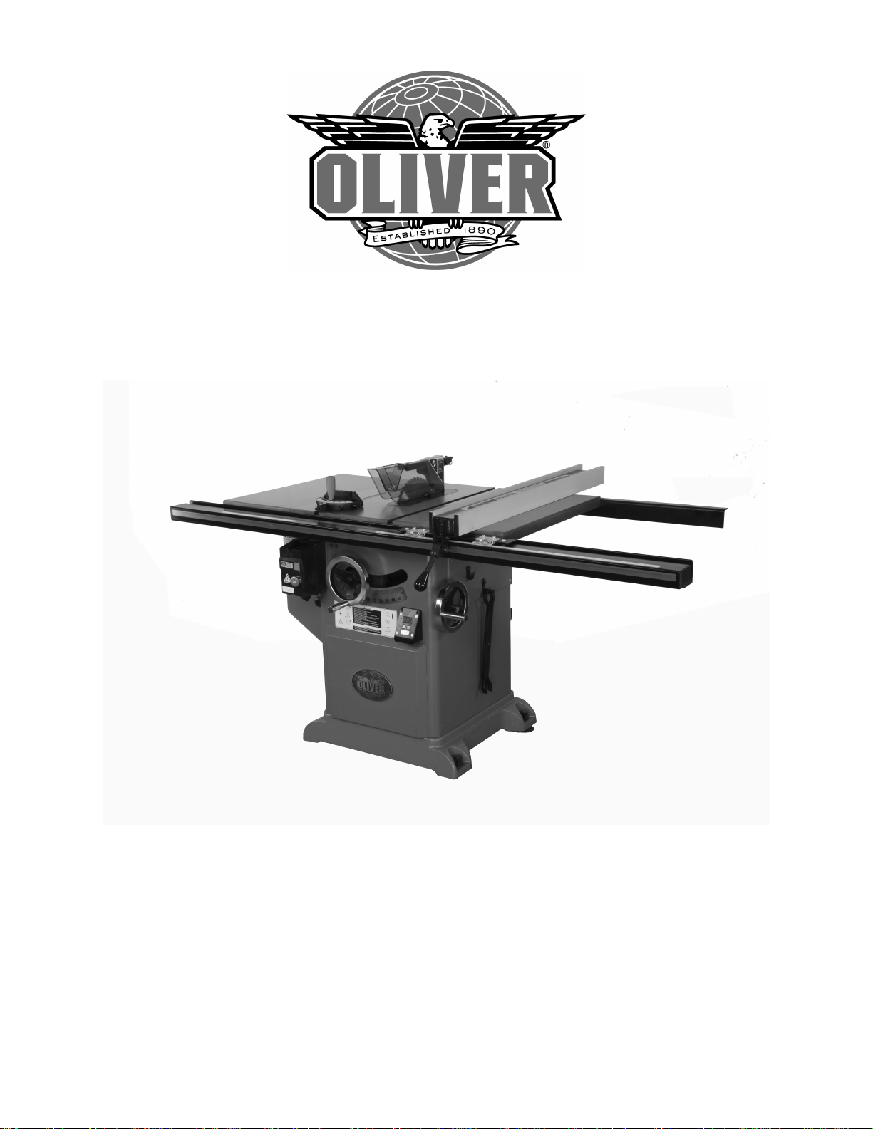
4016 10” Professional Tablesaw
Owner’s Manual
Oliver Machinery M-4016 04/2008
Seattle, WA Copyright 2003
[email protected] www.olivermachinery.net
Page 2

Warranty
Oliver makes every effort possible to assure that its equipment meets the highest possible standards of
quality and durability. All products sold by Oliver are warranted to the original customer to be free from
defects for a period of 2 (two) years on all parts, excluding electronics and motors, which are warranted
for 1 year. Oliver’s obligation under this warranty shall be exclusively limited to repairing or replacing (at
Oliver’s option) products which are determined by Oliver to be defective upon delivery F.O.B. (return
freight paid by customer) to Oliver, and on inspection by Oliver. This warranty does not apply to defects
due, directly or indirectly, to misuse, abuse, negligence, accidents, unauthorized repairs, alterations, lack
of maintenance, acts of nature, or items that would normally be consumed or require replacement due to
normal wear. In no event shall Oliver be liable for death, personal or property injury, or damages arising
from the use of its products.
Warning
Read this manual thoroughly before operating the machine. Oliver Machinery disclaims any liability for
machines that have been altered or abused. Oliver Machinery reserves the right to effect at any time,
without prior notice, those alterations to parts, fittings, and accessory equipment which they may deem
necessary for any reason whatsoever.
For More Information
Oliver Machinery is always adding new Industrial Woodworking products to the line. For complete, up-todate product information, check with your local Oliver Machinery distributor, or visit
www.olivermachinery.net
2
Page 3

WARNING
Read this manual completely and observe all warning labels on the machine. Oliver Machinery has made
every attempt to provide a safe, reliable, easy-to-use piece of machinery. Safety, however, is ultimately
the responsibility of the individual machine operator. As with any piece of machinery, the operator must
exercise caution, patience, and common sense to safely run the machine. Before operating this product,
become familiar with the safety rules in the following sections.
• Always keep guards in place and in proper operating condition.
• Use blade guard for every applicable operation including all through cuts. If guard is removed
for special non-through cuts such as dado and rabbet cuts, replace before further use of the
saw.
• Keep hands out of line with the saw blade.
• Use a push stick.
• Do not perform any operation freehand.
• Never reach around or over the saw blade.
1. If you are not properly trained in the use of a tablesaw do not use until the proper training has been
obtained.
2. Read, understand and follow the safety instructions found in this manual. Know the limitations and
hazards associated with this machine.
3. Electrical grounding: Make certain that the machine frame is electrically grounded and that a
ground lead is included in the incoming electrical service. In cases where a cord and plug are used,
make certain that the grounding plug connects to a suitable ground. Follow the grounding procedure
indicated in the National Electrical Code.
4. Eye safety: Wear an approved safety shield, goggles, or glasses to protect eyes. Common
eyeglasses are only impact-resistant, they are not safety glasses.
5. Personal protection: Before operating the machine, remove tie, rings, watch and other jewelry and
roll up sleeves above the elbows. Remove all loose outer clothing and confine long hair. Protective
type footwear should be used. Where the noise exceeds the level of exposure allowed in Section
1910.95 of the OSHA Regulations, use hearing protective devices. Do not wear gloves.
6. Guards: Keep the machine guards in place for every operation for which they can be used. If any
guards are removed for maintenance, DO NOT OPERATE the machine until the guards are
reinstalled.
7. Work area: Keep the floor around the machine clean and free of scrap material, saw dust, oil and
other liquids to minimize the danger of tripping or slipping. Be sure the table is free of all scrap,
foreign material and tools before starting to use the machine. Make certain the work area is well
lighted and that a proper exhaust system is used to minimize dust. Use anti-skid floor strips on the
floor area where the operator normally stands and mark off machine work area. Provide adequate
work space around the machine.
8. Material condition: Do not attempt to saw boards with loose knots or with nails or other foreign
material. Do not attempt to saw twisted, warped, bowed stock.
9. Operator position: Maintain a balanced stance and keep your body under control at all times.
10. Before starting: Before turning on machine, remove all extra equipment such as keys, wrenches,
scraps, and cleaning rags away from the machine.
3
Page 4

11. Careless acts: Give the work you are doing your undivided attention. Looking around, carrying on a
conversation, and “horseplay” are careless acts that can result in serious injury.
12. Disconnect all power sources: Before performing any service, maintenance, adjustments or when
changing blades. A machine under repair should be RED TAGGED to show it should not be used
until the maintenance is complete.
13. Job completion: If the operator leaves the machine area for any reason, the tablesaw should be
turned "off" and the blade should come to a complete stop before their departure. The key should be
placed in the “off” position, removed and given to a supervisor to prevent any unauthorized use of the
tablesaw.
14. Replacement parts: Use only genuine Oliver Machinery factory authorized replacement parts and
accessories; otherwise the warranty and guarantee is null and void.
15. Misuse: Do not use this Oliver tablesaw for other than its intended use. If used for other purposes,
Oliver disclaims any real or implied warranty and holds itself harmless for any injury or damage which
may result from that use.
16. Drugs, alcohol and medication: Do not operate this machine while under the influence of drugs,
alcohol, or any medication.
17. This machine is deigned for cutting wood products only. Do not use to cut any kind of metal or
substance other then wood.
18. Never start the saw while a work piece is in contact with the blade.
19. Raise or lower the blade only when the machine has been turned “off” and the blade has come to a
complete stop.
20. Miter Gauge and Rip Fence: Never use the miter gauge and rip fence at the same time.
21. Damaged Saw Blade: Never use a damaged saw blade or one that has been dropped. Check the
saw blade for cracks or missing teeth. Do not use a cracked or dull blade or one with missing teeth.
Make sure the blade is securely locked on the arbor.
22. Make sure the blade is running in the proper direction. Refer to the arrow on the blade. The teeth
should be pointing down when viewing from the front of the saw.
23. Alignment: Check the alignment of the splitter to the blade. Also, check the alignment of the fence
to the miter slot.
24. Health hazards: Some dust created by power sanding, sawing, grinding, drilling and other
construction activities contains chemicals known to cause cancer, birth defects or other reproductive
harm. Some examples of these chemicals are:
• Lead from lead-based paint.
• Crystalline silica from bricks and cement and other masonry products.
• Arsenic and chromium from chemically-treated lumber.
Your risk from these exposures varies, depending on how often you do this type of work. To reduce
your exposure to these chemicals, work in a well-ventilated area, and work with approved safety
equipment, such as those dust masks that are specifically designed to filter out microscopic particles.
Familiarize yourself with the following safety notices used in this manual:
CAUTION: (This means that if precautions are not heeded, it may result in minor or moderate injury
and/or possible machine damage)
WARNING: (This means that if precautions are not heeded, it could result in serious injury or possibly
even death).
4
Page 5

Table of Contents Page Number
Warranty......................................................................................................................................................2
Warnings..................................................................................................................................................3-4
Table of Contents........................................................................................................................................5
Specifications...............................................................................................................................................5
Contents of the Shipping Containers...........................................................................................................6
Machine Preparation and Setup..................................................................................................................7
Extension Wing Assembly...........................................................................................................................7
Handwheel Assembly..................................................................................................................................7
Rail Assembly..............................................................................................................................................8
Fence Assembly and Adjustment................................................................................................................9
Adjusting the Scale Reader.........................................................................................................................9
Calibrating the Digital Angle Readout........................................................................................................10
Leveling Table Insert..................................................................................................................................11
Splitter and Blade Guard Assembly...........................................................................................................11
Miter Gauge...............................................................................................................................................12
Controls.....................................................................................................................................................12
Dust Collection...........................................................................................................................................12
Electrical Connections...............................................................................................................................13
Replacing the Blade...................................................................................................................................13
Maintenance..............................................................................................................................................14
Troubleshooting....................................................................................................................................15-16
Specifications
Model Number.......................................................................................................................................4016
Blade Diameter (In)....................................................................................................................................10
Arbor Diameter (In)................................................................................................................................5/8"
Maximum Depth of Cut at 90 Degrees (In).................................................................................................3"
Maximum Depth of Cut at 45 Degrees (In)...........................................................................................2-1/4"
Maximum Cut to the Right of Blade..........................................................................................................36”
Maximum Cut to the Left of Blade.............................................................................................................12”
Dust Port Diameter (In)................................................................................................................................4
Table Dimensions w/Extensions (LxW).....................................................................................27” x 45-1/4"
Table Height (In).......................................................................................................................................36”
Blade Tilt..................................................................................................................................................Left
Arbor Speed RPM.................................................................................................................................3,450
Gross Weight (with 36” rails and fence)...................................................................................................639
5
Page 6
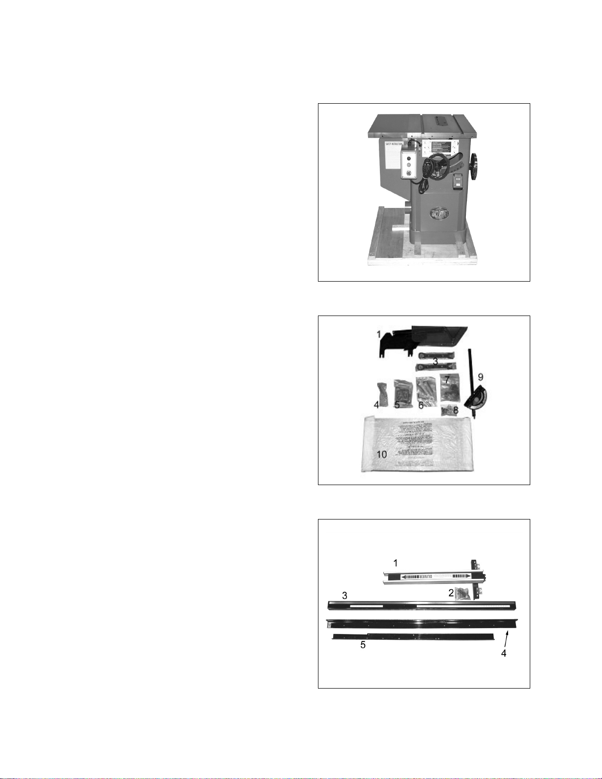
Oliver 4016, 10”Tablesaw
Contents of the Shipping Containers
Saw
Once the top is removed the saw will be as
shown with the left extension wing already
attached. Inspect for freight damage and
call the freight carrier if any.
Contents
Saw
Blade guard
3. Arbor wrenches
4. Wheel handle
5. Accessory holders
6. Tools
7. Hardware packet, 5/8 & 1” arbor
8. Extension wing hardware
9. Miter gage
10. Extension wing
Fence and Rail Assembly
Fence
Lock handle
Front guide
Front guide support bracket
Rear guide
Contents
Fence and Rail Assembly
6
Page 7
Machine Preparation and Setup
WARNING!
The equipment used to lift this machine must
have a rated capacity at, or above the weight
of the tablesaw. Failure to comply may
cause serious injury!
The tablesaw must be positioned on a smooth,
level surface. The area must be well lit and
have plenty of room to maneuver with large
pieces of wood.
Level the saw front to back and side to side
using a level placed on the table. Use shims
under the corners, if necessary, but make sure
the saw is stable before being placed into
service.
Clean all rust protected surfaces with a
commercial solvent. Do not use acetone,
gasoline, lacquer thinner or any type of
flammable solvent, or a cleaner that may
damage paint. Cover cleaned surfaces with
WD-40 or a 20W machine oil.
Figure 1
Pay particular attention to cleaning in the miter
slot and the faces of table and extension wing.
Extension Wing Assembly
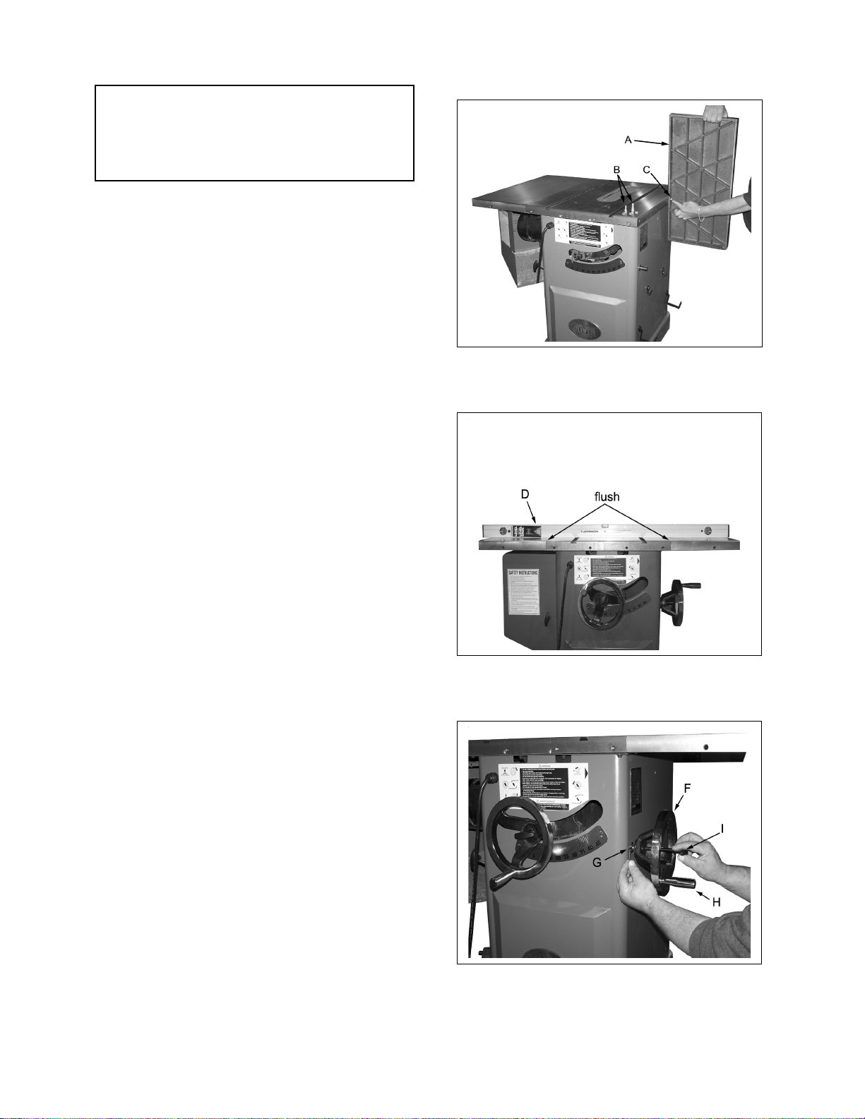
1. Attach extension wing (A, Figure 1) to table
with four hex head bolts, and four lock
washers (B, Figure 1). Snug but do not
tighten. Note: Start with one of the center
holes (C, Figure 1) to hold the wing in place.
2. Slide extension wing toward the front edge
of the saw table until two edges are flush.
3. Using a straight edge (D, Figure. 2), align
extension wing to saw table and tighten hex
cap bolts. Repeat for opposite wing.
Handwheel Assembly
1. Place handwheel (F, Figure 3) onto the saw
shaft. Use an allen key to lock the wheel
onto the shaft with the set screw (G, Figure
3). Insert and screw the locking handle (H,
Figure 3) and the wheel handle (I, Figure 3)
into their respective holes. Repeat for other.
Figure 2
Figure 3
7
Page 8
Rail Assembly
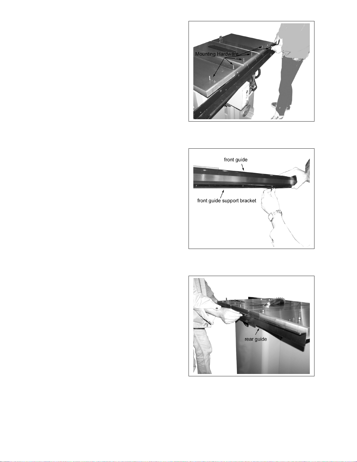
1. Rest the front guide support bracket on the
switch box as shown in Figure 4 and secure
into place using the chamfered bolts, nuts
and washers provided in hardware packet 7.
Note that the two outside holes require a nut
and washer as well as a bolt while the four
inside holes require the bolts only.
2. Set the front guide on the support bracket as
shown in Figure 5 and secure into place with
the short bolts provided in hardware packet
7.
Figure 4
3. Install the rear guide as shown in Figure 6
using the supplied hardware. Note that the
two outside holes require a nut and washer
as well as a bolt while the four inside holes
require the bolts and washers only.
Figure 5
Figure 6
8
Page 9
Fence Assembly and Adjustment
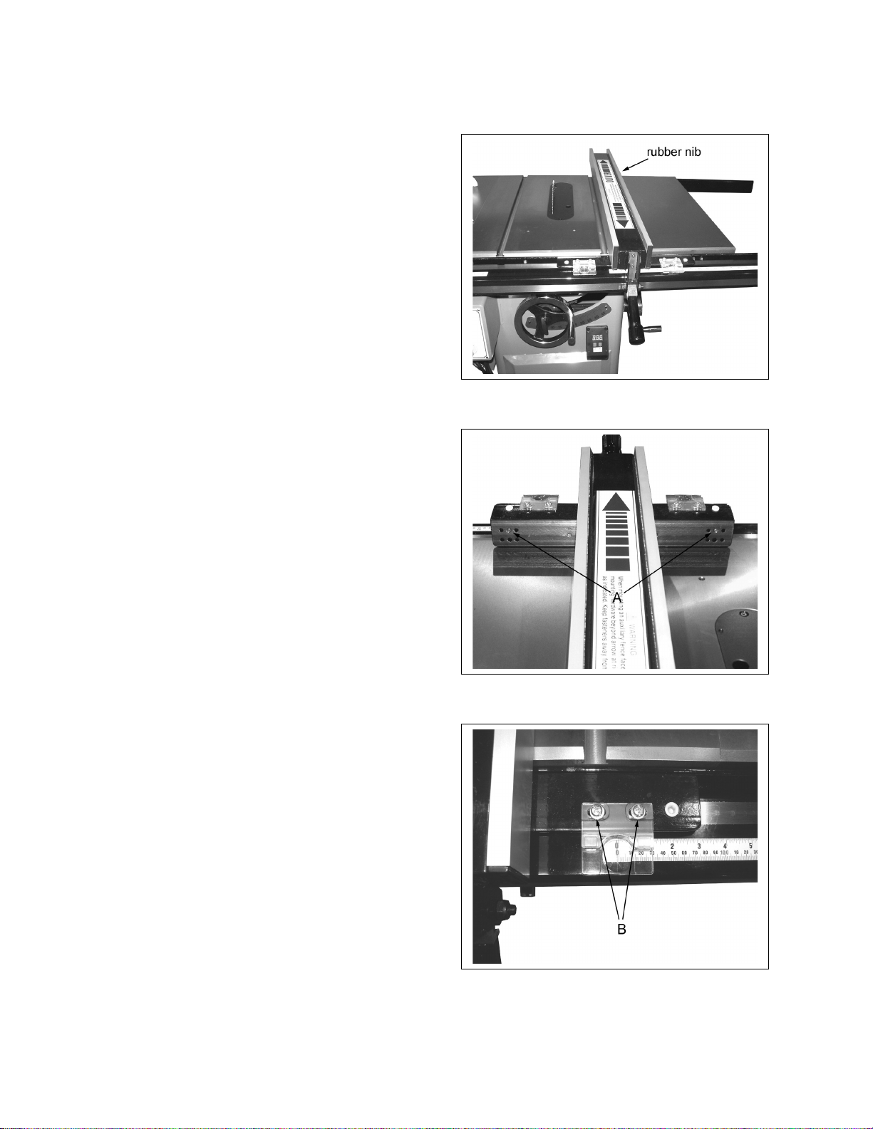
1. Place the fence on the guides as shown in
Figure 7. Look for the rubber nib on the
underside of the fence as shown and make
sure it lines up with the back support rail.
2. Align the fence with the miter guage slot as
shown in Figure 7 and check to see if the
fence is parallel to the slot.
3. If the fence is not parallel to the miter guage
slot, lift the fence off the guides and place it
on the table as shown in Figure 8. Turn the
appropriate screw, A to compensate for the
difference. Place the fence back on the
guides and check again for alignment to the
miter guage. If it is still mis-aligned, repeat
the procedure.
Adjusting the Scale Reader
1. Raise the blade to its maximum height.
Figure 7
2. Place the fence
on the guides on the right side of blade and
then slide the fence toward the blade.
Continue until the fence just touches the
saw teeth. Do not push too hard or the
blade will deflect.
3. Looking at the
right side scale reader, the red pointer
should match up with the zero mark. If not,
loosen the two screws, B, Figure 9 and slide
the viewer to align the mark with zero.
Tighten the screws.
4. Move the fence
to the left side of the blade and repeat the
procedure for the left side viewer.
Figure 8
Figure 9
9
Page 10
Calibrating the Digital Angle Readout
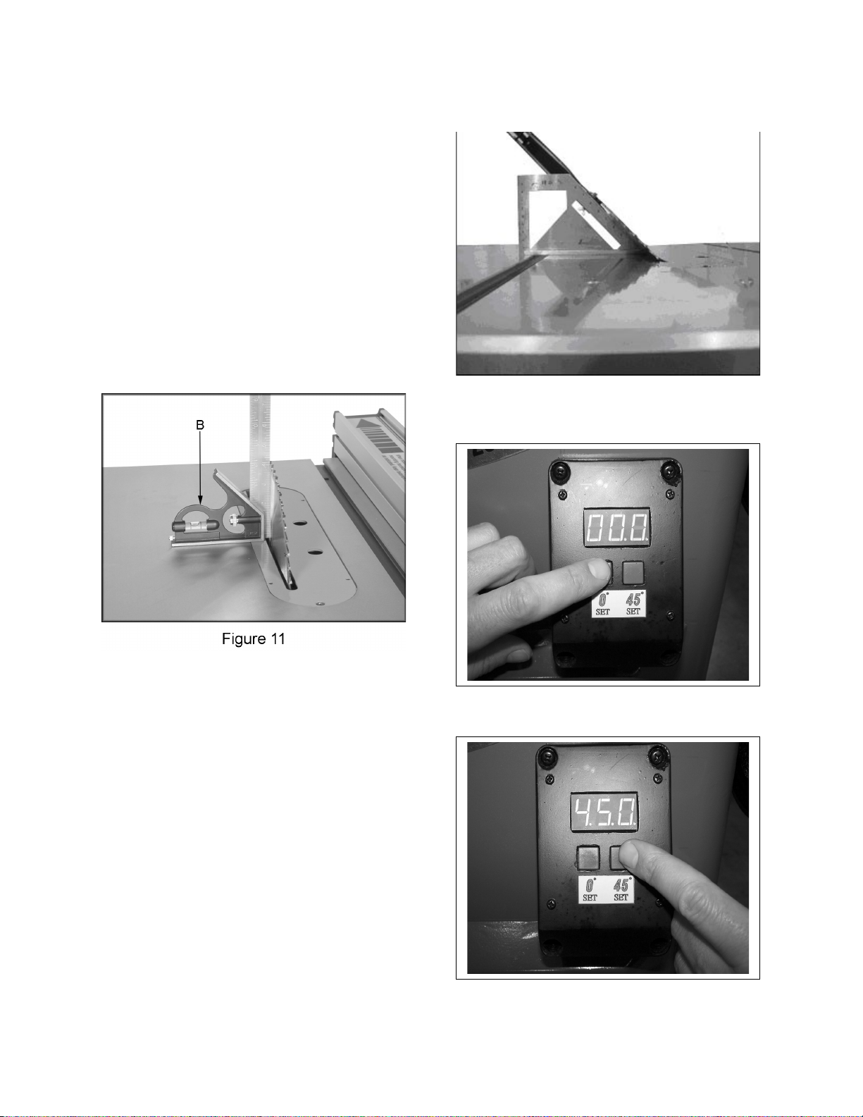
1. Place a square on the table as shown in
Figure 11 then turn the saw tilt wheel until the
blade comes to 90 degree.
2. Push and hold the 0° set button as shown in
Figure 14 until the display stops blinking. The 0°
is now set.
3. Tilt the blade to 45 degrees as shown in
Figure 12. Push and hold the 45° set button
as shown in Figure 15 until the display stops
blinking. At this point the angle display is
calibrated.
Figure 12
10
Figure 14
Figure 15
Page 11
Leveling Table Insert
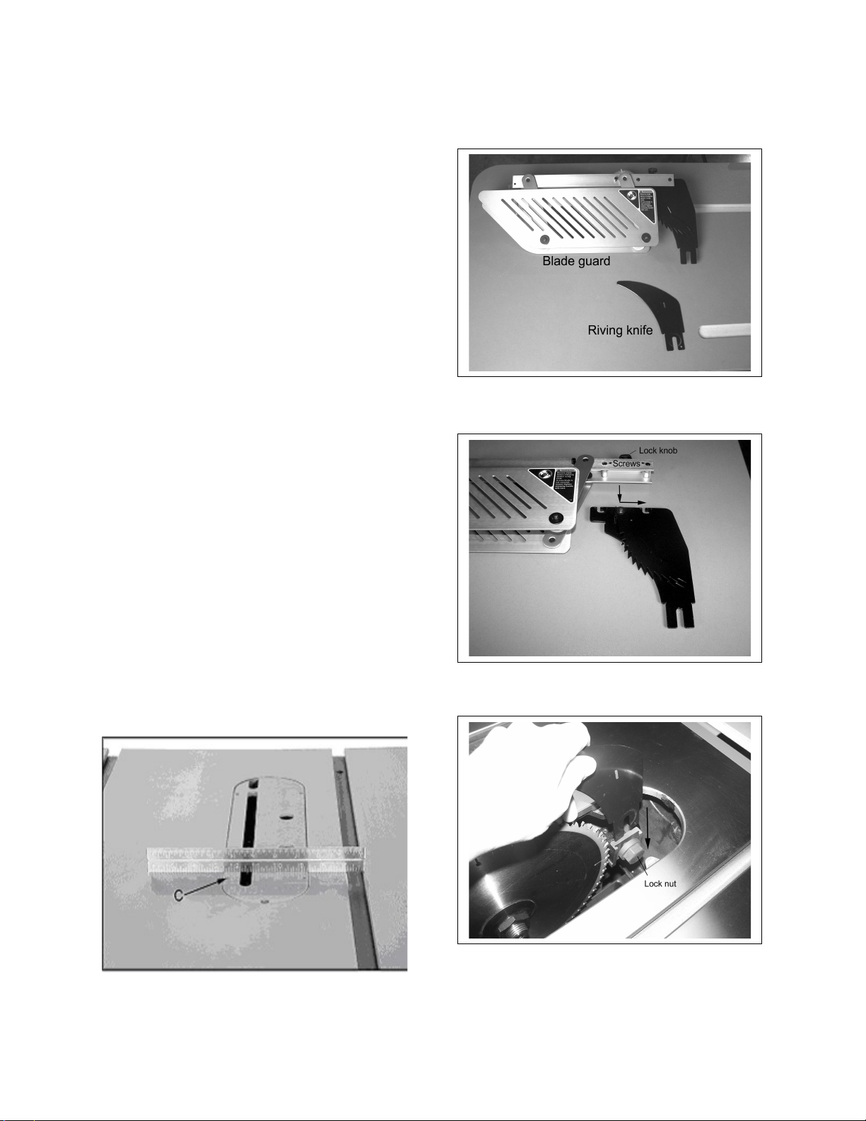
Adjust the table insert flush with the table by
turning the four leveling screws (C, Figure 16).
Place a straight edge across the table and
insert. Raise the insert until it just touches the
straight edge. Check both the front and rear
section of the insert.
Splitter and Blade Guard Assembly
The table saw comes equipped with both a riving
knife and blade guard (see Figure 17). It is
always recommended to use the blade guard
whenever possible. However, when doing
narrow cuts when the guard would interfere with
the fence or any other cuts in which the blade
guard would pose a problem, replace the guard
with the riving knife. Installation is the same for
both. For ease of installation, the blade guard
can be disassembled by loosening the lock knob
and separating the splitter from the guard as
shown in Figure 18. It may be necessary to
loosen the two screws as indicated in the
picture.
Figure 17
1. Disconnect saw from power source.
2. Remove table insert by loosening the screw
at the front of insert.
3. Loosen the lock nut then insert the fork of
the riving knife between the nut head and
backing plate as shown in Figure 19. Lock
into place.
4. Re-install the table insert.
Figure 18
Figure 16
Figure 19
11
Page 12
Miter Gauge
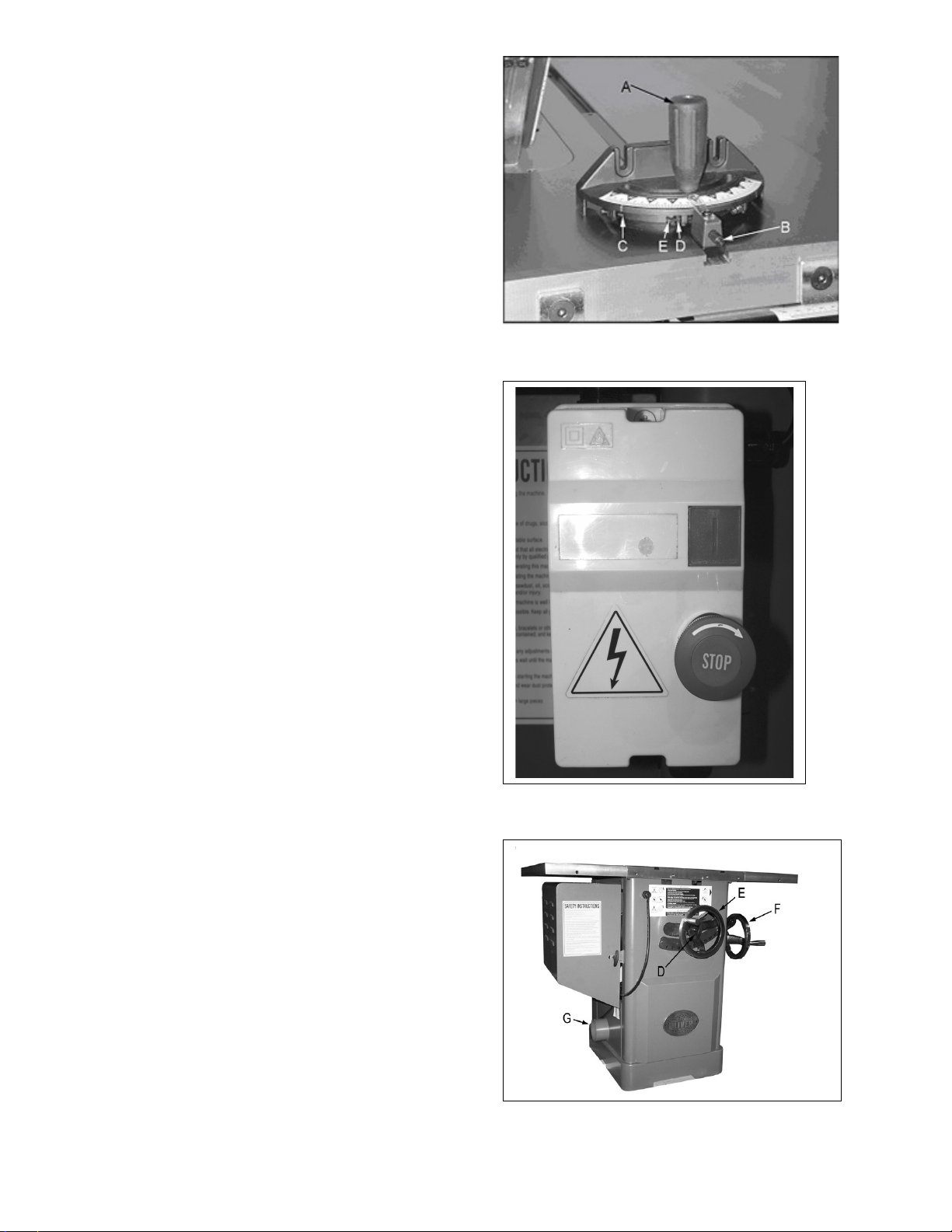
1. Slide the miter gauge bar into the miter
gauge slot in table. Loosen the handle (A,
Figure 23) and pull out indexing rod (B,
Figure 23) to pivot the miter gauge body.
2. Push the indexing rod in to engage the
preset stops (C, Figure 23).
3. Adjust stops by loosening the hex nut (D,
Figure 23) and adjusting screw (E, Figure
23).
Note: Always make test cuts. The scale is for
reference. There are two holes in the miter
gauge fence used to attach a wooden fence.
Controls (see Figures 24 & 25)
A. Emergency Stop Button: Stops all
functions of machine.
B. Start: Starts saw blade rotation. Will not
work if the “Emergency Stop” switch is
engaged, or the key is in the “OFF” position.
Figure 23
C. Handwheel Lock: There is a handwheel
lock on both handwheels. Loosen lock to
turn handwheel and tighten when blade is in
desired location.
D. Raising and Lowering Hand wheel:
Loosen hand wheel lock. Turn handle
clockwise to raise the blade. The blade
should be 1/8”-1/4” above the top of work
piece, or 3-5 blade teeth above the top of
work piece.
E. Tilting Hand wheel: Loosen hand wheel
lock. Turn handle counter-clockwise to tilt
blade to the left.
Dust Collection
There is a 4” dust port (G, Figure 25) located on
the side of saw cabinet. Make sure dust
collection system has sufficient capacity and
suction for your tablesaw. Always turn on dust
collection system before starting the tablesaw.
Figure 24
12
Figure 25
Page 13

Electrical Connections
WARNING!
Electrical connections and wiring must be
done by a qualified electrician. The machine
must be properly grounded. Failure to
comply may cause serious injury!
This saw is available in both 1-Phase and 3Phase versions.
Electrical Connections for a 3-Phase Unit
This saw is 3-Phase, 220V/440V pre-wired
220V. If you need to switch the tablesaw from
220V to 440V have a qualified electrician make
the changes. Oliver Machinery recommends
using a dedicated circuit.
Make sure the voltage of your power supply
matches the specifications on the motor plate of
the machine.
With 3-Phase power verify the blade is turning in
the proper direction. Turn the saw on and make
sure the direction of the blade spins toward the
user when standing in front of the saw. If it does
not, disconnect the power source and reverse
any two power leads.
4. Replace the blade followed by the flange
and arbor nut. Tighten the arbor nut while
holding the arbor in place.
Note: Make sure the blade and arbor are clean
before installing a new blade. The blade teeth
should point down when viewing from the front
of saw.
Figure 25
Electrical Connections for a 1-Phase Unit
This saw is 1-Phase, 220V only. Oliver
Machinery recommends using a dedicated
circuit.
Make sure the voltage of your power supply
matches the specifications on the motor plate of
the machine.
Replacing the Blade
The blade guard has been removed for photos,
but it is possible to change the blade without
removing the blade guard.
1. Disconnect saw from power source.
2. Remove the table insert and raise the blade
completely.
3. Use the two provided arbor wrenches to
loosen the arbor nut, as shown in Figure 25.
Place one wrench on the arbor nut and one
on the flats located on the arbor. Remove
the nut, flange and blade.
13
Page 14
Maintenance
WARNING!
Disconnect the machine from power source
before proceeding with any maintenance, or
troubleshooting! Failure to comply may
cause serious injury!
Periodically clean the inside of the machine for
dust control. Use an air hose to blow out dust
from motor fan and motor cover.
Use a wire brush to clean trunnions and worm
gears. Apply white lithium grease or powdered
graphite to lubricate worm gears, and trunnions.
Keep pulleys and belts free from dirt, dust, oil
and grease.
Replace worn v-belts as needed.
Remove rust from the tabletop with WD-40 and
a Scotch-Brite™ Hand Pad. Keep a light coat of
WD-40 on the table top when not in use
Figure 27
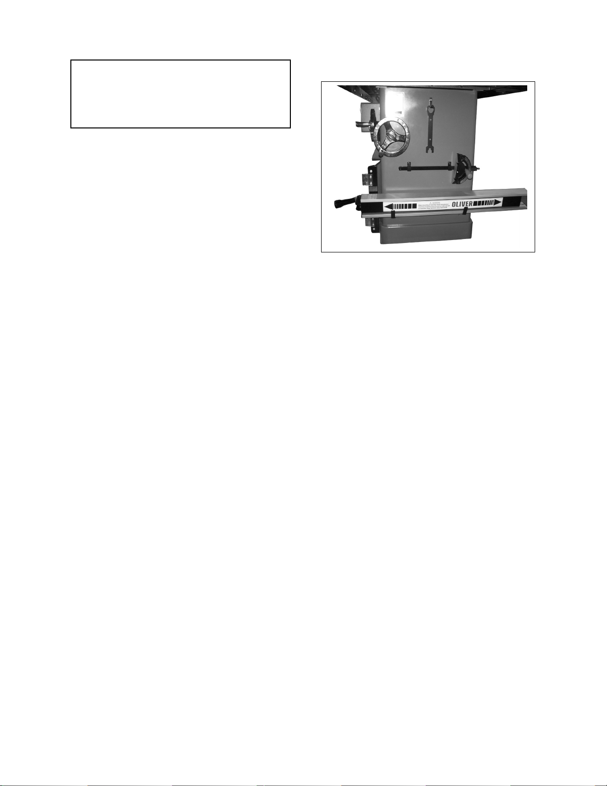
Accessory Holders
See Figure 27 for the correct placement of
the accessory holders.
14
Page 15

.
Troubleshooting
Description of Symptoms Possible Cause Corrective Action
Machine will not start
Blade does not come up to speed
Does not make accurate 45° or
90° cuts
1. Fuse blown or circuit breaker
tripped
2. Cord Damaged
3. Faulty switch
4. Not connected to power
source
5. Connected to wrong voltage
6. Key in the “OFF” position
7. Emergency stop button
pressed
1. Cable too light or too long
2. Low current
3. Motor not wired for correct
voltage
1. Stops not adjusted correctly
2. Angle pointer not set
accurately
3. Miter gauge out of adjustment
1. Replace fuse or reset circuit
breaker
2. Have cord replaced
3. Replace switch
4. Check connection
5. Check voltage
6. Insert key and turn to “ON”
position
7. Rotate emergency stop button
clockwise until it pops out
1. Replace with adequate size
cable
2. Contact local electric
company
3. Refer to motor nameplate for
correct voltage
1. Check blade with combination
square and adjust stops
2. Check blade with combination
square and adjust pointer
3. Adjust miter gauge
Saw makes unsatisfactory cuts
Material binds blade when ripping
1. Dull blade
2. Blade mounted backwards
3. Gum or pitch on blade
4. Incorrect blade for cut
1. Fence not aligned with blade
2. Warped wood
3. Excessive feed rate
4. Splitter not aligned with blade
1. Sharpen or replace blade
2. Turn blade around
3. Remove blade and clean
4. Change blade to correct type
1. Check and adjust fence
2. Select another piece of wood
3. Reduce feed rate
4. Align splitter with blade
15
Page 16
Saw vibrates excessively
1. Stand on uneven floor
2. Damaged saw blade
3. Bad V-belts
4. Bent pulley
5. Improper motor mounting
6. Loose hardware
1. Reposition on flat, level
surface
2. Replace saw blade
3. Replace V-belts
4. Replace pulley
5. Check and adjust motor
6. Tighten hardware
Material kicked back from blade
Blade does not raise or tilt freely
1. Rip fence out of alignment
2. Splitter not aligned with blade
3. Feeding stock without rip
fence
4. Splitter not in place
5. Dull blade
6. Letting go of material before it
is past blade
7. Anti-kick back paws dull
Sawdust and debris in raising
and tilting mechanisms
1. Align rip fence with miter slot
2. Align splitter with blade
3. Install and use rip fence
4. Install and use splitter (with
guard)
5. Replace blade
6. Push material all the way past
blade before releasing work
7. Replace or sharpen anti-kick
back paws
Clean and regrease
16
Page 17

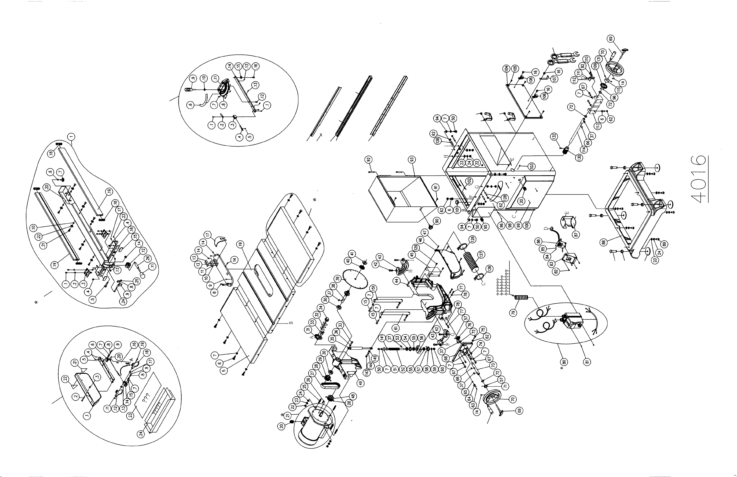
4016 Part's List
Index Part Number Descriptions Spec. QTY Old P/N
0
850429-000
116 230114-906 Handle 2 PJ010018
117 040203-000 Open Wrench 11*13 1 HQ020800
118 040205-000 Open Wrench 14*17 1 HQ021100
119 040207-000 Open Wrench 22*24 1 HQ021400
120 040004-000 Hex. Wrench 4mm 1 HQ010500
121 040005-000 Hex. Wrench 5mm 1 HQ010600
122 040006-000 Hex. Wrench 6mm 1 HQ010700
123 040401-000 Screwdriver 1*75 1 HQ070100
124 041305-003 Poly Bag 275*185*0.05t 1 HR043800
142 380205-901 Nut TW5/8"-12(/in) 1 TH010011
0 850340-000 Bagged Hardware for Miter Gauge Resting Rack 1
16 049201-102 Hex. Screw w/Flat Washer M8*1.25P*12/(13B*6.5H) 2
97 170541-904 Fence Seat Resting Rack 2 TH020024
125 041103-001 Poly Bag 120*100*0.1t 1 HR040200
0
850389-000
146 000006-105
147 008011-100
148
172277-902 Base Packing Block
149 041201-002 Poly Bag 190*130*0.05t 1 HR023000
0 850483-000 Bagged Hardware for Adjusting Plate 1
32 172330-000 Adjusting Plate 3 TH250069
150 041401-002 Bubble Bag 100*70 1
1 922230-000 Spreader Guard Ass'y 1
.1 250180-627 Blade Guard 1 TH010033
.2 000002-309 Hex. Screw M6*1.0P*50 1
.3 008304-200
.4 000302-101
.5 172335-904 Rod 1 TH250025
.6 130234-903
.7 360865-901 Spreader Fixing Shaft 2 TH250047
.8 280160-901 Spring 2 TH250048
.9 010204-000 E-Ring ETW-7 2 HF031600
.11 010301-000 SPN Ring SPN-4 1 HF060200
.12 172336-904
.13 280162-901 Spreader Spring (Right) 1 TH250049
.14
090149-910 Anti-Kick Fixing Bracket
.15 360864-000 Pin 1 TH250051
.16
172337-904
.17 280163-901 Spreader Spring (Left) 1 TH250050
.18 172338-904 Anti-Kick Pawl (Right) 1 TH250043
.19 380495-901 Anti-Kick Paw Fixing Rod 1
.20 011002-110 Spring Pin 4*16 1 HG010909
.21 572736-000 Warning Label (Right) 1 RTJ040007
.22 572737-000 Warning Label (Left) 1 RTJ040008
Bagged Hardware 1
Bagged Hardware for Cast Iron Base 1
Adjusting Screw
Hex. Nut
M16*2.0P*60 4 RTJ040006
M16*2.0P(24B*13H) 4 HC011600
4 RTJ040005
Nylock Nut
Round Head Screw
Connecting Rod Fixing Support
Anti-Kick Pawl Left
M6*1.0P(10B*7H) 1 HW040600
M4*0.7P*6 2 HA040402
1 TH250044
1 TH250042
1 TH250046
Spreader 1 TH250017
1
Page 18

.23 041303-019 Poly Bag 700*280*0.05t 1 HR025600
.24
520001-554
Spreader Cardboard Box 480*60*216mm 1
*2 TH27-42 Fence Ass'y
3 921782-000 Miter Guage Ass'y 1 RTJ0405
.1 003303-105
Round Head Screw
3/16"-24NC*3/8" 3 HB040905
.2 250193-620 Indicator 1 TH010304
.3 130053-901 Packing 1 TH010305
.4 360381-901 Fixing Shaft 1 TH120606
.5 043311-000 O-Ring (P type) P5 1 HM080300
.6 571151-000 Miter Guage Label 1 TH010303
.7 003305-106
Round Head Screw
5/32"-32NC*5/8" 3 HB040807
.8 009001-100 Hex. Nut 5/32"-32NC(8B*3.8H) 3 HD010200
.9 250146-000 Handle 1 TH030301
.10 006002-051 Flat Washer 8.5*18*3t 1 HY013700
.11 090067-008 Miter Guage 1 TH010302
.12 290017-901 Shoulder Screw 1 TH010308
.13 230222-901 Positioning Pin 3 TH120602
.14 380614-904 Positioning Bar 1 RTJ030041
.15 380069-901
.16 000403-105
Round Guide Piece
Flat Head Screw
M6*1.0P*6 1 HA050402
1 TH030303
.17 041303-019 Poly Bag 700*280*0.05t 1 HR025600
.18 041102-003 Poly Bag 165*80*0.05t 1 HR020400
*4 TH27-83 Extension Wing Ass'y
5 050963-008 Extension Wing 1
6 000003-105 Hex. Screw M8*1.25P*25 (13B*5.5H) 6 HA010513
7 006305-100 Spring Washer 8.2*15.4 17 HE021100
8 002101-101
Pan Head Lock Screw
M5*0.8P*20 1 HA350310
9 250703-615 Blade Insert 1 TH270013
10 420009-000 Wearing Plate 2-sided Tape (Left) 1 TH270023
11 420010-000 Wearing Plate 2-sided Tape (Right) 1 TH270024
12 270048-902
13 270049-902
Wearing Plate (Left)
Wearing Plate (Right)
1 TH270006
1 TH270007
14 001902-105 Set Lock Screw M6*1.0P*12 9
15 000104-111 CAP Screw M8*1.25P*35 4 HA020519
16 049201-102 Hex. Screw w/Flat Washer M8*1.25P*12/(13B*6.5H) 3
17 172331-904 Riving Knife 1 TH250005
19 050940-008 Table 1 TH270019
20 021306-000 Strain Relief PGA16-14B 2 HP042600
*21 TH27-01 Motor Ass'y TJ0A
22 008007-100 Hex. Nut M10*1.5P(17B*8H) 7 HC011000
23 006307-100 Spring Washer 10.2*18.5 13 HE021300
24 006001-069 Flat Washer 10*20*3.0t 13 HA040705
25 360761-901 Bolt 3 RTJ030021
26 012003-010 Key 5*5*30 1 HH010417
27 014314-000
Belt 180J-9
1
28 001902-102 Set Lock Screw M6*1.0P*8 4 HA320403
29 380384-902 Blade Pulley 1 RTH160013
30 030214-000 Ball Bearing 6004-2NSE 2 HJ030900
2
Page 19

31 110066-000 Riving Knife Bracket 1 TH250018
32 172330-000 Adjust Plate 3 TH250069
33 000104-104 CAP Screw M8*1.25P*16 3 HA020508
34
35
36
380778-902
660145-000
160076-000
Lock Bolt 1
Air Pressure Rod 1 TH270026
Bushing 1 TH270020
37 012003-006 Key 5*5*18 5 HH010410
38
380858-901
Arbor 1 TH270003
39 390017-000 Blade 10''*40T 1
40 170518-901 Blade Washer 1 TH010012
41 380052-901 Blade Nut (5/8") 1 TJ010075
42 000105-103 CAP Screw M10*1.5P*30 4 HA020616
43 050585-008 Trunnion Bracket 2 OE320004
44
050937-000
Trunnion 1 TH270001
45 172517-901 Dust Guide 1
46
47
48
49
250704-615
000303-207
380383-902
050938-000
Blade Side Cover 1 TH270017
Round Head Screw
M5*0.8P*20 5 HS040610
Motor Pulley 1 RTH160008
Up/Down Lift Bracket 1 TH270002
50 000003-102 Hex. Screw M8*1.25P*16 4 HA010508
51
006001-040 Flat Washer
52
360871-901
Up/Down Rod 1 TH270022
8*30*3.0t 1 HE018300
53 160073-000 Up/Down Rod Bushing 1 TH250062
54
660144-000 Ring 1
TH270010
55 031005-000 Ball Bearing 51102 2 HJ130300
56
130237-903 Rod Fixing Bracket
1 TH270029
57 001901-101 Set Lock Screw M5*0.8P*5 6 HA320301
58
380767-000 Bevel Gear
1
59 006001-078 Flat Washer 10.5*19*1.5t 1 HE015800
60 008307-100
61
360825-000
Nylock Nut
Column 1 TH270011
M10*1.25P(17B*12H) 1 HC040900
62 008006-100 Hex. Nut M8*1.25P(13B*6.5H) 7 HC010800
63 000304-103
Round Head Screw
M6*1.0P*12 1 HA040705
64 171697-156 Indicator 1 TJ020014
65 006503-100 Lock Washer 6.4*11(BW-6) 1 HE040900
66 130061-000 Key 2 TJ010041
67 000104-108 CAP Screw M8*1.25P*25 5 HA020515
68
050939-000
Gear Rotary Plate 1 TH270004
69 920662-000 Lock Bolt Ass'y 2 TJ0103
360036-000 Lock Bolt 1 TJ010301
250433-615 Lock Handle 1 TJ010302
70 240066-000 Handle Wheel 2 TH270027
71
130228-903 Fixing Ring
1
72 006006-106 Flat Washer 19.1*25.4*1.6 4 TH120081
73
360867-901
74 360355-901
75 000003-107 Hex. Screw
76
380768-000
Elevation Control Shaft 1 TH270018
Pin
M8*1.25P*35
Bevel Gear 1
2 PJ010044
1 HA010519
130131-000
3
Page 20

77
000103-108
CAP Screw M6*1.0P*25 3 HA020413
78 006303-100 Spring Washer 6.1*12.3 3 HE020900
79 730063-004 Wire Protector ASW-16-B(16*20/300mm) 1
*80 TH27-02 Switch Ass'y TJ0B
81 003303-101
82 000303-202
83
250547-615
84 000301-206
Round Head Screw
Round Head Screw
3/16"-24NC*1/2"
M5*0.8P*8 6
Sensor Box 1
Round Head Screw
M3*0.5P*8 4
HB040906
2
85 006002-139 Flat Washer 3*8*1.0t 4
86 950348-000 Sensor Ass'y 220~460V(450mm) 1
.1 490498-000 Sensor Plate 220~460V 1
.2 490434-000 Sensor Connecting Wire 450mm 1
.3 250665-615 Elevation Sensor Box 1
.4 001106-601 Round Head Self-Tapping Screw M2*0.63P*6L 3
87 250632-615 Dust Guard Cover 1 RTJ030046
88 050941-000
Cast Iron Base
1 TH270021
89 000004-102 Hex. Screw M10*1.5P*25 6 HA010613
90 230131-000 Fix Nob Screw 1 SS011277
91 340007-615 Packing-Up Block 2 PG010046
92 230196-908 Clamp Screw 2 RTJ030029
93 172369-000 Cover 1 TH270014
94 006001-041 Flat Washer 8.2*22*3.0t 3 HE018400
95 021315-000 Strain Relief MG25A-16B 1 HP042900
96 000302-101
Round Head Screw
M4*0.7P*6 4 HA040402
98 006001-001 Flat Washer 4.3*10*1.0t 2 HE010600
99 000401-104
Flat Head Screw
M4*0.7P*10 2 HA050204
100 172332-000 Body 1 TH270009
101
021507-000 Wire Protector
1
102 230297-615 Fixed Chain 2 TH100081
103 001102-604 Round Head Self-Tapping Screw M4*1.59P*12 2 HS180305
104 172266-000 Right Cover 1
105 000403-104
Flat Head Screw
M6*1.0P*20 4 HA050410
106 170542-904 Miter Gauge Resting Rack 2 TH020025
107 170965-904 Fixin Support 1 TJ010090
108 172033-904 Wrench 2 RTJ030037
109 172110-000 Sensor Piece 1 TH240005
110 006001-009 Flat Washer 5.2*10*1.0t 2 HE011100
111
001101-205 Round Head Self-Tapping Screw
M3*1.06P*6 2
112 170262-000 L-Shape Board 1
113 050582-008 Worm Shaft Support 1 OE320003
114 360807-901 Worm Shaft 1
115 130031-000 Fixing Ring 1 RTJ030047
126 042608-000 Dust Hose Clamp Ø60-80mm 2
127 042601-000 Dust Hose 2.5”*1000mm 1
128
001903-107 Set Lock Screw M8*1.25P*50 4 HA030528
129 002701-103 Round Head Hex Screw w/Flat Washer M6*1.0P*16/6.3*12*1.0t 2 HA380300
130 320381-000 Worm Shaft 1 TJ020011
131 001903-104 Set Lock Screw M8*1.25P*10 2 HA320504
132 011003-106 Spring Pin 5*28 1 HG011016
4
Page 21

*133 TH27-73 Fence Ass'y
*134 TH27-10 Name Plate
*135 TH27-14 Manual
5
Page 22
 Loading...