

Page 1
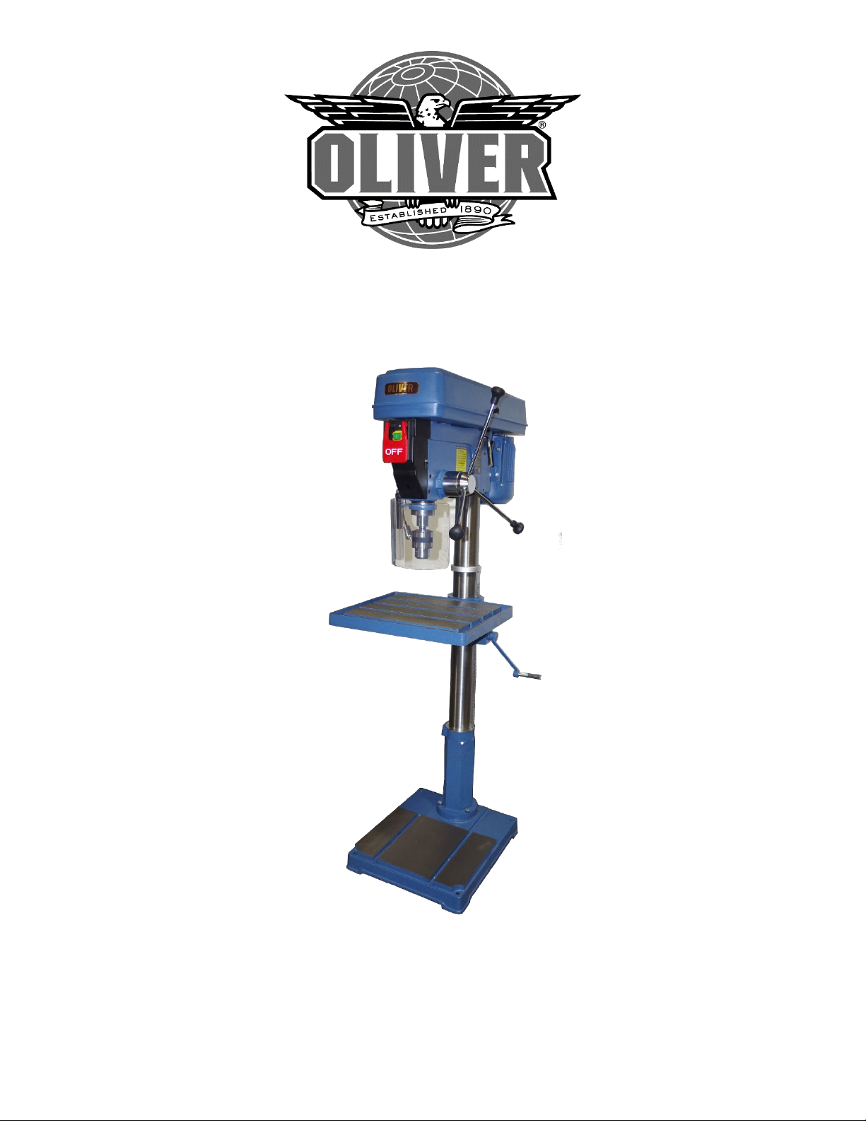
10063.0001 Drill Press
Owner’s Manual
Oliver Machinery M-10063 11/2018
Page 2

Page 3

SAFETY INSTRUCTION READ BEFORE OPERATION
To help ensure safe operation, please take a moment to learn the machine’s applications and
limitations, as well as potential hazards. Oliver Machinery disclaims any real or implied warranty and
holds itself harmless for any injury that may result from the improper use of its equipment.
1. Do not operate the drill press when tired, distracted, or under the effects of drugs, alcohol or
any medication that impairs reflexes or alertness.
2. The working area should be well lit, clean and free of debris.
3. Keep children and visitors at a safe distance when the drill press is in operation; do not permit
them to operate the drill press.
4. Childproof and tamper proof your shop and all-machinery with locks, master electrical switches
and switch keys, to prevent unauthorized or unsupervised use.
5. Stay alert! Give your work your undivided attention. Even a momentary distraction can lead to
serious injury.
6. Fine particulate dust is a carcinogen that can be hazardous to health. Work in a well-ventilated
area and whenever possible use a dust collector and wear eye, ear and respiratory protection
devices.
7. Do not wear loose clothing, gloves, bracelets, necklaces or other jewelry while the drill press is
in operation.
8. Be sure that adjusting wrenches, tools, drinks and other clutter are removed from the machine
and/or the table surface before operating.
9. Keep hands well away from the drill bit and all moving parts. Use a hold-down or clamp to
secure the stock, and use a brush, not hands, to clear away chips and dust.
10. Be sure that the drill bit is securely installed in the chuck before operation.
11. Be sure the drill bit has gained full operating speed before beginning to drill.
12. Always use a clean, properly sharpened bit. Dirty or dull bits are unsafe and can lead to
accidents.
13. Use suitable work piece support if the work piece does not have a flat surface.
14. Do not push or force the bit into the stock. The drill will perform better and more safely when
working at the rate feed for which it was designed.
Page 4

SAFETY INSTRUCTION CONTINUED
15. Avoid working from awkward or off-balance positions. Do not overreach and keep both feet on
floor.
16. Keep guards in place and in working order. If a guard must be removed for maintenance or
cleaning be sure it is properly re-attached before using the tool again.
17. Never leave the machine unattended while it is running or with the power on.
18. Use of parts and accessories NOT recommended by Oliver Machinery may result in equipment
malfunction or risk of injury.
19. Never stand on machinery. Serious injury could result if the tool is tipped over or if the drill bit is
unintentionally contacted.
20. Always disconnect the tool from the power source before servicing or changing accessories such
as bits, or before performing any maintenance, cleaning, or if the machine will be left
unattended.
21. Make sure that the switch is in the “OFF” position before plugging in the power cord.
22. Make sure the tool is properly grounded. If equipped with a 3-prong plug, it should be used with
a three-pole receptacle. Never remove the third prong.
23. Do not use this drill press for other than its intended use. If used for other purposes, Oliver
Machinery disclaims any real implied warranty and holds itself harmless for any injury, which
may result from that use.
Prop 65 Notice:
WARNING: Some dust created by power sanding, sawing, grinding, drilling, and other construction activities
contains chemicals known to the State of California to cause cancer and birth defects or other reproductive harm.
Some examples of these chemicals are:
• lead from lead-based paints,
• crystalline silica from bricks and cement and other masonry products, and
• arsenic and chromium from chemically treated lumber.
Your risk from exposure to these chemicals varies, depending on how often you do this type of work. To reduce
your exposure, work in a well-ventilated area and with approved safety equipment, such as dust masks that are
specially designed to filter out microscopic particles. For more information go to www.P65Warnings.ca.gov.
Page 5

ELECTRICAL RERQUIREMENTS
BEFORE CONNECTING THE MACHINE TO THE POWER SOURCE, VERIFY THAT THE VOLTAGE OF YOUR
POWER SUPPLY CORRESPONDS WITH THE VOLTAGE SPECIFIED ON THE MOTOR I.D. NAMEPLATE.
A POWER SOURCE WITH GREATER VOLTAGE THAN NEEDED CAN RESULT IN SERIOUS INJURY TO THE
USER AS WELL AS DAMAGE TO THE MACHINE. IF IN DOUBT, CONTACT A QUALIFIED ELECTRICIAN
BEFORE CONNECTING TO THE POWER SOURCE.
THIS TOOL IS FOR INDOOR USE ONLY. DO NOT EXPOSE TO RAIN OR USE IN WET OR DAMP LOCATIONS.
GROUNDING INSTRUCTIONS
In the event of an electrical malfunction or short circuit, grounding reduces the risk of electric shock. The
motor of this machine is wired for 115 Volt Single Phase operation ONLY and is equipped with a 3conductor cord and a 3-prong grounding plug to fit a grounded type receptacle
Do not remove the 3rd prong (grounding pin) to make it fit into an old 2-hole wall socket or extension
cord. If an adaptor plug is used it must be attached to the metal screw of the receptacle
The use of an adaptor plug may be illegal in some areas. Check your local codes. If you have any doubts
or if the supplied plug does not correspond to your electrical outlet, consult a qualified electrician
before proceeding.
CIRCUIT CAPACITY
Make sure that the wires in your circuit are capable of handling the amperage draw from your machine,
as well as any other machines that could be operating on the same circuit. If you are unsure, consult a
qualified electrician.
If the circuit breaker trips or the fuse blows regularly, your machine may be operating on a circuit that is
close to its amperage draw capacity. However, if an unusual amperage draw does not exist and a power
failure still occurs, contact a qualified technician or our service department.
EXTENSION CORDS
Oliver Machinery does not recommend the use of an extension cord with your machine. However, if
you must use an extension cord, make sure it has an amperage suitable for the rating on the motor ID
nameplate. An undersized cord will cause a drop-in line voltage resulting in loss of power and
overheating.
Any extension cord used must feature a 3-prong grounding plug as described under grounding
instructions. Follow the rules listed.
Page 6

Oliver Machinery Model 10063.001
Assembly Instructions
• Review the parts breakdown and keep it for reference when putting your drill press together.
The assembly steps will reference the item numbers from the parts list.
• Remove all parts from the packaging, but do not dispose of until you are finished.
• Lay out the parts in an unobstructed area, some pieces such as the head will need two people to
safely move.
• All components of the 10063.001 are heavy and require two or more people to assemble.
• If you have any questions during assembly, please contact Oliver Machinery at 800-559-5065 or
email at [email protected]
Assembling the Drill Press
1. Bolt the COLUMN PEDESTAL (99) and COLUMN (80) to the BASE (100) using three BOLTS (97)
and WASHERS (98).
2. Remove the RACK COLLAR (78) from the COLUMN (80) by loosening the SCREW (78) and
carefully sliding the collar preventing any binding. Set the RACK (77) to the side.
3. Locate the TABLE BRACKET (81) and TABLE (91) making sure the WORM GEAR (88) and HELICAL
GEAR (89) are in their proper location.
4. Place the RACK (77) into the table bracket. The tapered end of the rack faces upward, and the
squared end faces down.
5. Slide both pieces onto the COLUMN (80). Take care to hold in position as it is a tight fit.
6. Fit the squared end of the rack in the COLUMN PLATE (110) of the RACK SEAT (111). Secure the
top of the rack by installing the rack collar. Do not bind the rack or over tighten the set screw.
7. Slide the TABLE CRANK HANDLE (86) on to the worm gear shaft aligning the set screw with the
flat surface and tighten.
8. Using at least two people, lower the HEAD (109) on the column and secure in alignment with
the base using the two SET SCREWS (60). Use hex wrench supplied.
9. Tighten the three FEED HANDLES (65) into the FEED PINION SHAFT (64).
10. Remove the SCREW (4) from the PULLEY COVER (3) and reverse it through the hole. Tighten
KNOB (5) on to the screw.
11. Keep the DRIFT KEY (74) and hex wrenches for future use.
12. Remove the protective coating from all surfaces using a rag and environmentally safe cleaner.
Do not use any chemical that may damage the painted surfaces.
.
Page 7

Installing the Drill Chuck Guard
1. Locate the CHUCK GUARD (116) and GUARD SHAFT (117).
2. Assemble the CONNECT BAR (118) to the guard shaft with NUT (120) and SPRING WASHER
(119) and tighten.
3. Remove the SNAP RING (132) from the FIXED SEAT CONNECT BAR (121).
4. Slide the fixed seat connect bar through the FIXED SEAT (122) and reinstall the snap ring. Be
sure to position the flat surface of the fixed seat connect bar facing to the rear of the machine.
This will activate the safety switch allowing the drill press to operate.
5. Slide the connect bar, chuck guard, and guard shaft assembly onto the FIXED SEAT CONNECT
BAR (121) and secure with NUT (120) and SPRING WASHER (119) and tighten.
6. The SET SCREW (123) will hold the drill chuck guard at the desired height. Do not over tighten.
7. NOTE: The drill chuck guard must be installed, or the machine will not operate. This is a safety
feature and is electrically monitored.
Installing the Drill Chuck
1. Remove the protective coating from the ARBOR (75), DRILL CHUCK (76) internal tapered
surface, and SPINDLE (73) internal tapered surface. It is extremely important these are clean.
2. Place the drill chuck on the short-tapered end of the arbor.
3. Insert the arbor into the spindle and twist until the flat portion mates with the spindle.
4. Adjust the drill chuck so all fingers are recessed into the body.
5. Place a block of wood on the table and using the feed handles, apply pressure to secure the drill
chuck in place.
6. To remove the drill chuck, lower the spindle to the full depth, rotate the drill chuck until arbor
can be seen, and place the DRIFT KEY (74) through the hole. Give a slight tap with a mallet and
the drill chuck and arbor will drop out. Be sure to catch the drill chuck to prevent damage. It is
much easier to do this with two people.
Page 8

Drill Press Use Instructions
Drilling Guidelines
• Always wear safety glasses.
• Use clean and sharp drill bits intended for a power drill.
• Clamp the workpiece securely. Never hold it by hand.
• Make sure to use the recommended speed for the drill size and workpiece material.
Adjusting the Table Height
1. Loosen the LOCK HANDLE (82) and LOCK HANDLE (87).
2. Rotate the TABLE CRANK HANDLE (86) to raise or lower.
3. Tighten both lock handles at the desired position.
Table Swing Position
1. Loosen the LOCK HANDLE (82) and LOCK HANDLE (87).
2. Swing TABLE (91) to the desired position.
3. Tighten the LOCK HANDLE (82) and LOCK HANDLE (87).
4. For large pieces the BASE (100) can be used as the table.
Changing Speeds
1. Always disconnect the drill press from the power source before changing speeds.
2. Raise the PULLEY COVER (3).
3. Refer to the speed chart for the desired speed and belt arrangement.
4. Loosen the THUMB SCREWS (45) on each side of the head and release the belt tension.
5. Relocate the belts to the desired speed arrangement.
6. Push the MOTOR (54) away from the head using the ADJUSTMENT LEVER (49) to tension the
belts.
7. Tighten the thumb screws to hold the belt tension.
8. Proper tension is less than ½” deflection when squeezing the belt together.
Page 9

Table Tilt Adjustment
1. Loosen both HEX NUTS (92).
2. Remove the lower bolt.
3. Tilt the table to the desired position.
4. Tight both hex bolts, do not replace the lower bolt.
5. When moving back to the normal drilling position, replace the lower bolt and tighten both hex
nuts.
Depth Stop Adjustment
1. Set the bottom DEPTH STOP LOCK NUT (38) to the desired depth setting.
2. Tighten the second lock nut against the first nut to secure it in position.
Laser Adjustment
1. Using a small bit (1/16” or less) drill a hole in a scrap piece of wood the same thickness as your
workpiece.
2. Turn on the laser and move the light so both cross hairs intersect the hole.
3. The laser is now adjusted for operation.
4. If you change the table height or thickness of your workpiece, start with step 1 and adjust for
your next set of holes.
Page 10

Page 11
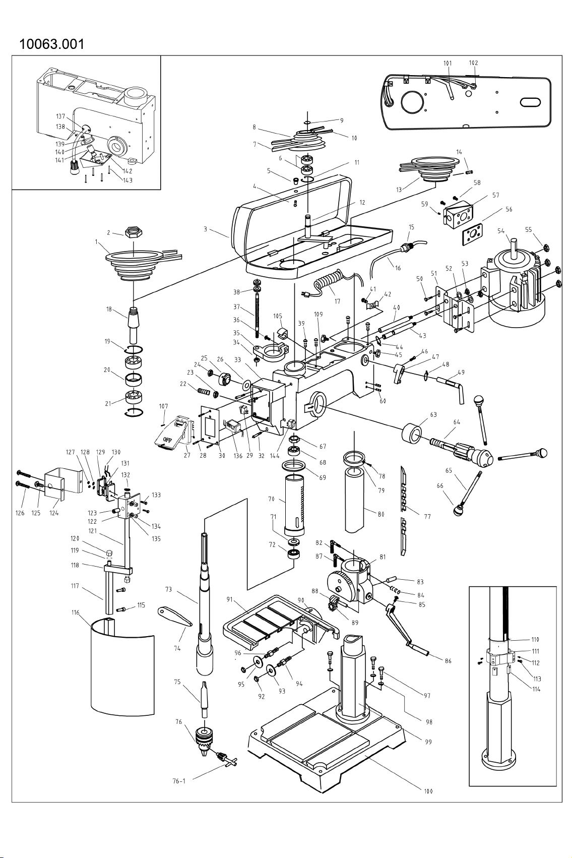
10063.001
Page 12

NO. PART NO. DESCRIPTION
PART LIST FOR 10063.001
1 10063-1 SPINDLE PULLEY 1
2 10063-2 NUT 1
3 10063-3 PULLEY COVER 1
4 10063-4 SCREW 1
5 10063-5 KNOB 1
6 BB-6203ZZ 6203ZZ BALL BEARING 2
7 10063-7 A-40 V-BELT 1
8 10063-8 IDLER PULLEY 1
9 10063-9 RETAINING RING 1
10 10063-10 A-25 V-BELT 1
11 10063-11 RETAINING RING 1
12 10063-12 PULLEY SHAFT ASSEMBLY 1
13 10063-13 MOTOR PULLEY 1
14 10063-14 SET SCREW 1
15 10063-15 STRAIN RELEF 1
16 10063-16 SWITCH TO MOTOR CORD 1
17 10063-17 POWER CORD WITH MOLDED PLUG 1
18 10063-18 SPINDLE PULLEY INSERT 1
19 10063-19 RETAINING RING 2
20 10063-20 BEARING SPACER 1
21 BB-6007ZZ 6007ZZ BALL BEARING 2
22 10063-22 SCREW 1
23 10063-23 HEX NUT 1
24 10063-24 HEX NUT 1
25 10063-25 RETURN SPRING AND CAP 1
26 10063-26 WASHER 1
27 10063-27 ON/OFF SWITCH ASSEMBLY 1
28 10063-28 SCREW 3
29 10063-29 LIGHT SWITCH 1
30 10063-30 SWITCH BACK PLATE 1
32 10063-32 SCREW 3
33 10063-33 SW ITCH BOX 1
34 10063-34
35 10063-35 DEPTH STOP BRACKET 1
36 10063-36 BOLT 1
37 10063-37 DEPTH STOP ROD 1
38 10063-38 DEPTH STOP LOCK NUT 2
39 10063-39 SCREW 4
40 10063-40 LH MOTOR BRACKET ROD 1
41 10063-41 SCREW 1
42 10063-42 CORD CLAMP 1
43 10063-43 RH MOTOR BRACKET ROD 1
NUT 1
QTY
Page 13
NO. PART NO. DESCRIPTION
QTY
PART LIST FOR 10063.001
44 10063-44 RETAINING RING 1
45 10063-45 WING SCREW 2
46 10063-46 SCREW 1
47 10063-47 ADJUSTMENT CAM 1
48 10063-48 RETAINING RING 1
49 10063-49 ADJUSTMENT LEVER 1
50 10063-50 HEX HEAD BOLT 4
51 10063-51 MOTOR PLATE 1
52 10063-52 SPRING WASHER 2
53 10063-53 HEX NUT 2
54 10063-54 1.5 HP MOTOR 1PH 115V 1
55 10063-55 HEX NUT 4
56 10063-56 RUBBER GASKET 1
57 10063-57 JUNCTION BOX 1
58 10063-58 SCREW 4
59 10063-59 SCREW 1
60 10063-60 SET SCREW 2
63 10063-63 SPACER 1
64 10063-64 PINION SHAFT 1
65 10063-65 FEED HANDLE 3
66 10063-66 HANDLE KNOB 3
67 10063-67 SPINDLE NUT 1
68 BB-6005ZZ 6005ZZ BALL BEARING 1
69 10063-69 QUILL BUMPER 1
70 10063-70 QUILL 1
71 TB-51107 51107 THRUST BEARING 1
72 BB-6007ZZ 6007ZZ BALL BEARING 1
73 10063-73 SPINDLE MT-3 1
74 10063-74 DRIFT KEY 1
75 10063-75 ARBOR MT-3 / JT-3 1
76 10063-76 3/4 DRILL CHUCK w/KEY 1
76-1 10063-76-1 KEY ONLY 1
77 10063-77 RACK 1
78 10063-78 SCREW 1
79 10063-79
80 10063-80. COLUMN 1
81 10063-81 TABLE RACKET w/scale 1
81-1 10063-81-1 TILT SCALE ONLY w/rivets 1
82 10063-82 LOCK HANDLE 1
83 10063-83 GEAR SHAFT 1
84 10063-84 SET SCREW 3
85 10063-85 HEX HEAD SCREW 1
RACK COLLAR 1
Page 14
NO. PART NO. DESCRIPTION
QTY
PART LIST FOR 10063.001
86 10063-86 TABLE CRANK HANDLE
1
87 10063-87 LOCK HANDLE 1
88 10063-88 ELEVATING WORM 1
89 10063-89 HELICAL GEAR 1
90 10063-90 POINTER 1
91 10063-91 TABLE 1
92 10063-92 HEX NUT 2
93 10063-93 WASHER 1
94 10063-94 LH ARM STUD 1
95 10063-95 WASHER 1
96 10063-96 RH ARM STUD 1
97 10063-97 BOLT 3
98 10063-98 SPRING WASHER 3
99 10063-99 COLUMN PEDESTAL 1
100 10063-100 BASE 1
101 10063-101 CORD FOR LAMP 1
102 10063-102 GROMMET 1
103 10063-103 CAPACITOR (not shown) 1
104 10063-104 CAPACITOR COVER (not shown) 1
105 10063-105 KEY HOLDER 1
107 10063-107 SCREW 1
109 10063-109 HEADSTOCK CASTING 1
110 10063-110 COLUMN PLATE 1
111 10063-111 RACK SEAT 1
112 10063-112 HEX HEAD BOLT M4 2
113 10063-113 HEX HEAD BOLT M10 2
114 10063-114 STOP BLOCK 2
115 10063-115 CAP SCREW 2
116 10063-116 CHUCK GUARD 1
117 10063-117 GUARD SHAFT 1
118 10063-118 CONNECT BAR 1
119 10063-119 SPRING WASHER 1
120 10063-120 NUT 1
121 10063-121 FIXED SEAT CONNECT BAR 1
122 10063-122
123 10063-123 SET SCREW 1
124 10063-124 SW ITCH PLATE 1
FIXED SEAT 1
Page 15
NO. PART NO. DESCRIPTION
QTY
PART LIST FOR 10063.001
125 10063-125 SCREW 1
126 10063-126 SET SCREW
127 10063-127 NUT 2
128 10063-128 SCREW 2
129 10063-129 RH LIMIT SWITCH 1
130 10063-130 LIMIT SWITCH CORD 1
131 10063-131
132 10063-132 SHAFT CLIP RING 1
133 10063-133 SET SCREW 2
134 10063-134 NUT 2
135 10063-135 SPRING WASHER 2
136 10063-136 LASER TRANSFORMER 1
137 10063-137 LED LIGHT 1
138 10063-138 SCREW 2
139 10063-139 SCREW 3
140 10063-140 LASER COVER 1
141 10063-141 KNOB 1
142 10063-142 LASER BOX 1
LH LIMIT SWITCH 1
2
143 10063-143 SCREW 4
144 10063-144 LASER SWITCH 1
 Loading...