

Olimpia BS-1638, BS-1642, BS-1646, BS-1638/MAR, BS-1642/MAR Installation, Programming, Use
...Page 1
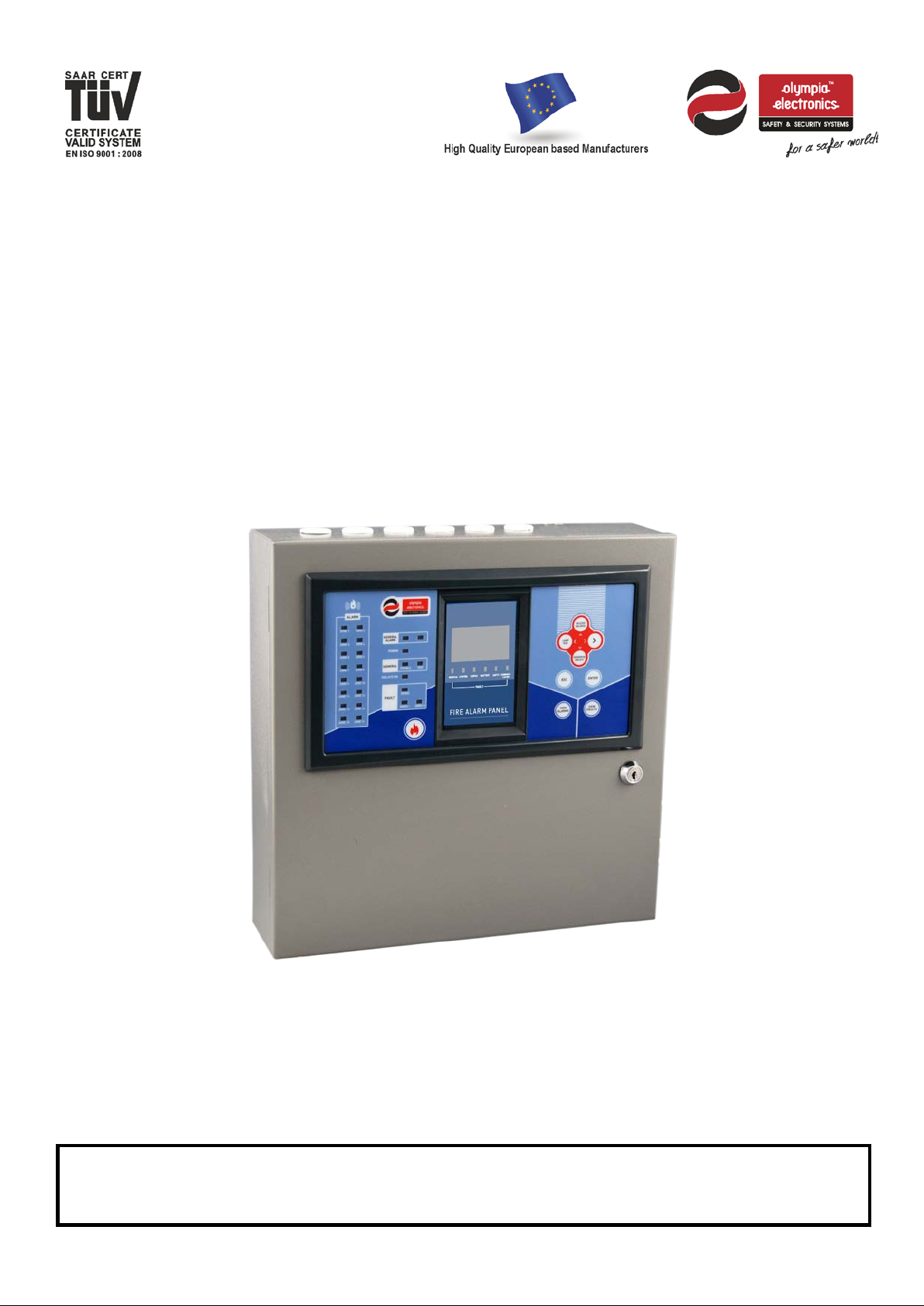
BS-1638, BS-1642,
BS-1646
Conventional fire detection panels 8, 12 and 16
Zones
Installation
Programming
Use
WARNING!!! READ THE WHOLE MANUAL BEFORE EVERY INSTALLATION
Page 2

2 / 47
Date
30/9/2016
File
Document code
921163800_09_007
Page
2 from 47
Contents
1 General information ---------------------------------------------------------------------------------------------------------------------- 4
1.1 Description------------------------------------------------------------------------------------------------------------- 4
1.2 Safety ------------------------------------------------------------------------------------------------------------------- 4
1.3 Indicators and controls ---------------------------------------------------------------------------------------------- 5
1.3.1 Fascia of the panel --------------------------------------------------------------------------------------------- 5
1.3.2 Keyboard of panel ---------------------------------------------------------------------------------------------- 6
1.3.3 Indication LEDs ------------------------------------------------------------------------------------------------- 6
2 Functions 8
2.1 Operation states of the panel ------------------------------------------------------------------------------------- 8
2.2 Normal operation - quiescent state ------------------------------------------------------------------------------ 8
2.3 Alarm State ------------------------------------------------------------------------------------------------------------ 9
2.4 Fault state------------------------------------------------------------------------------------------------------------- 10
2.5 Access Level 1 functions ------------------------------------------------------------------------------------------ 11
2.6 Basic menu for Access Level 1 ---------------------------------------------------------------------------------- 11
2.6.1 Events Menu ---------------------------------------------------------------------------------------------------- 13
2.6.2 Test Led --------------------------------------------------------------------------------------------------------- 13
2.7 Information------------------------------------------------------------------------------------------------------------ 13
2.7.1 Zone Information ----------------------------------------------------------------------------------------------- 15
3 User Menu 17
3.1 Enable – Disable menu ------------------------------------------------------------------------------------------- 19
3.2 Delay menu ----------------------------------------------------------------------------------------------------------- 19
3.3 Adjusting the time and date -------------------------------------------------------------------------------------- 19
3.4 Changing the user code ------------------------------------------------------------------------------------------- 20
3.5 Use a P/C to access the user menu ---------------------------------------------------------------------------- 21
3.5.1 Using a personal computer ----------------------------------------------------------------------------------
21
3.5.2 Panel information ---------------------------------------------------------------------------------------------- 22
3.5.3 Zone Information ----------------------------------------------------------------------------------------------- 22
3.5.4 All events -------------------------------------------------------------------------------------------------------- 23
3.5.5 Network Information ------------------------------------------------------------------------------------------ 23
3.5.6 User Menu ------------------------------------------------------------------------------------------------------ 23
4 Installation ---------------------------------------------------------------------------------------------------------------------------------- 24
4.1 Safety ------------------------------------------------------------------------------------------------------------------ 24
4.2 Installation ------------------------------------------------------------------------------------------------------------ 24
4.2.1 Mounting the panel on the wall ----------------------------------------------------------------------------- 25
4.3 Cables ----------------------------------------------------------------------------------------------------------------- 26
4.4 Describing the interior of the panel ----------------------------------------------------------------------------- 27
4.5 Connecting the power supply cables (220-240V AC) ------------------------------------------------------ 27
4.6 Connecting the batteries. ----------------------------------------------------------------------------------------- 29
4.7 Connecting the Zones --------------------------------------------------------------------------------------------- 30
4.8 Connecting the Sirens --------------------------------------------------------------------------------------------- 31
Page 3
3 / 47
Date
30/9/2016
File
Document code
921163800_09_007
Page
3 from 47
4.9 Connection to a network panels ------------------------------------------------------------------------------------ 32
The interface cable is bipolar twisted. The connection topology is parallel so the cable should be
passed from one panel to another and there must not be any branches. ------------------------------------- 32
They can be connected up 16 panels on a network. --------------------------------------------------------------- 32
4.10 Other Connections ----------------------------------------------------------------------------------------------- 33
5 Technician Menu ------------------------------------------------------------------------------------------------------------------------- 35
5.1 Test menu ------------------------------------------------------------------------------------------------------------ 36
5.2 Setup menu ---------------------------------------------------------------------------------------------------------- 37
5.2.1 Number of zones ---------------------------------------------------------------------------------------------- 37
5.2.2 Sirens ------------------------------------------------------------------------------------------------------------- 37
5.2.3 Aux Relay ------------------------------------------------------------------------------------------------------- 37
5.2.4 Network configuration panel -------------------------------------------------------------------------------- 39
5.3 Settings Menu ------------------------------------------------------------------------------------------------------- 39
5.3.1 Select Language ----------------------------------------------------------------------------------------------- 39
5.3.2 Annual check warning ---------------------------------------------------------------------------------------- 39
5.3.3 Reset defaults -------------------------------------------------------------------------------------------------- 40
5.3.4 Annual check done -------------------------------------------------------------------------------------------- 40
5.3.5 Changing the technician code ------------------------------------------------------------------------------ 40
5.4 Clearing the events log -------------------------------------------------------------------------------------------- 40
5.5 Resetting the alarm counter -------------------------------------------------------------------------------------- 41
5.6 Network settings ---------------------------------------------------------------------------------------------------- 41
5.7 Technician menu using the Ethernet --------------------------------------------------------------------------- 41
5.7.1 Zone names ---------------------------------------------------------------------------------------------------- 43
5.7.2 Setting the date and hour ------------------------------------------------------------------------------------ 43
5.7.3 Other information ---------------------------------------------------------------------------------------------- 44
5.7.4 ΙΡ address ------------------------------------------------------------------------------------------------------- 44
6 Technical Characteristics - Specifications -------------------------------------------------------------------------------------- 45
6.1 Certification ----------------------------------------------------------------------------------------------------------- 47
Page 4
4 / 47
Date
30/9/2016
File
Document code
921163800_09_007
Page
4 from 47
Congratulations for your selection to buy this product.
1 General information
Olympia Electronics - European manufacturers.
1.1 Description
The family consists of 3 panels (8, 12 and 16 zones) with identical controls and indications. They have 2
outputs for sirens, an alarm relay, a fault relay and a programmable auxiliary relay. For there operation,
two A-986 (12V/7Ah) batteries are required. Alternatively two Α-961 (12V/9Ah) batteries can be used for
greater autonomy.
In detail the BS-1638 panel has 8 zones, the BS-1642 has 12 zones and the BS-1646 has 16 zones.
All functions and indications are according to the European norms ΕΝ 54-2 and ΕΝ 54-4.
The panels offer up to 16 zones and are suitable for large installations such as shopping malls, hotels
and factories.
They offer a wide range of settings and characteristics for controlling the installation equipment and
sirens which can be easily adjusted using a P/C via an Ethernet connection.
1.2
Safety
A device cannot be considered that it is used correctly if you do not read the accompanying
documents that are supplied.
This product must be installed, commissioned and serviced only by qualified and trained personnel
according to:
The regulations concerning the installation of electrical devices in a building.
The fire saf ety regulations .
The instructions of the manufacturer.
- The product operates with a voltage of 220-240V ΑC/50-60Hz and is a class 1 unit. (For safety and
operation reasons it is required that the power earth cable of the building is connected).
- It must be installed to the current electrical installation using a dedicated fuse with a label «Fire
detections system – Do not close the switch».
Page 5
5 / 47
Date
30/9/2016
File
Document code
921163800_09_007
Page
5 from 47
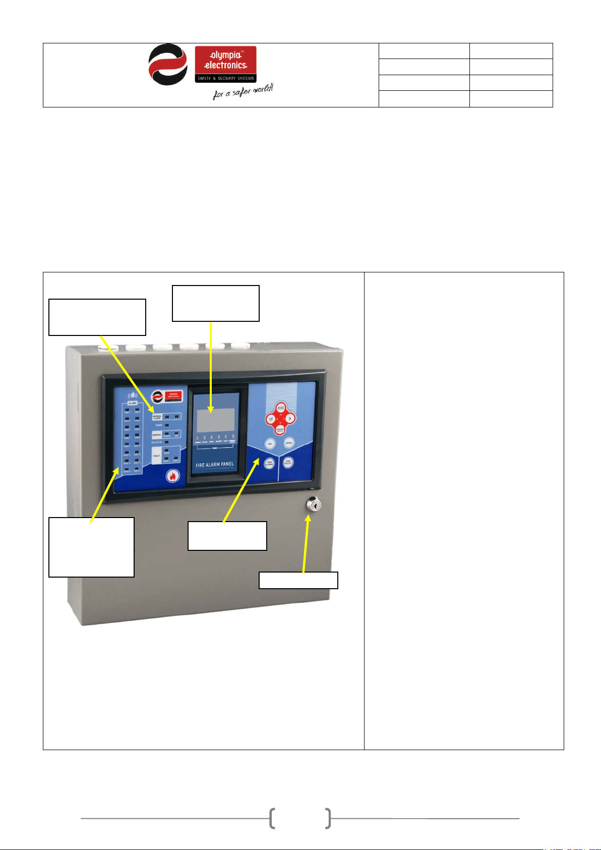
The LEDs give us general
if we have
navigating left, right, up or down,
(exit or one level
Alarm Zone
LEDs
Operation
Keyboard
Status
Liquid Crystal
Lock
Indicators and controls
1.3
We can read messages in the graphical display area whereas the LED indicators show basic warnings
(alarms, faults, disabled sections).
The front of the panel has all the required controls for its operation.
The operation of the panel is done easily using the 8 button keyboard.
In general we can see:
1.3.1 Fascia of the panel
The panel has a liquid crystal
Indication LEDs
Display
display and an array of indicator
LEDs via which the user can see its
status.
information (for example,
an alarm the General Alarm led will be
lit.) and the display shows additional
information for the event. ( e.g. Alarm
1, on Zone 7 on the 2nd floor).
status
indication
Figure 1-1. Fascia of the panel
To the right of the screen we can
see 8 keys that are used to operate
the panel. These k eys correspond to
basic operations of the panel such as
enter (select), esc
back) e.t.c (see below).
In general, with the pressing of a key
we can either do an operation or a
menu with various options is shown.
(see paragraph 1.3.2).
The panel also has a safety lock
(see Figure 1-1).
Page 6
6 / 47
Date
30/9/2016
File
Document code
921163800_09_007
Page
6 from 47
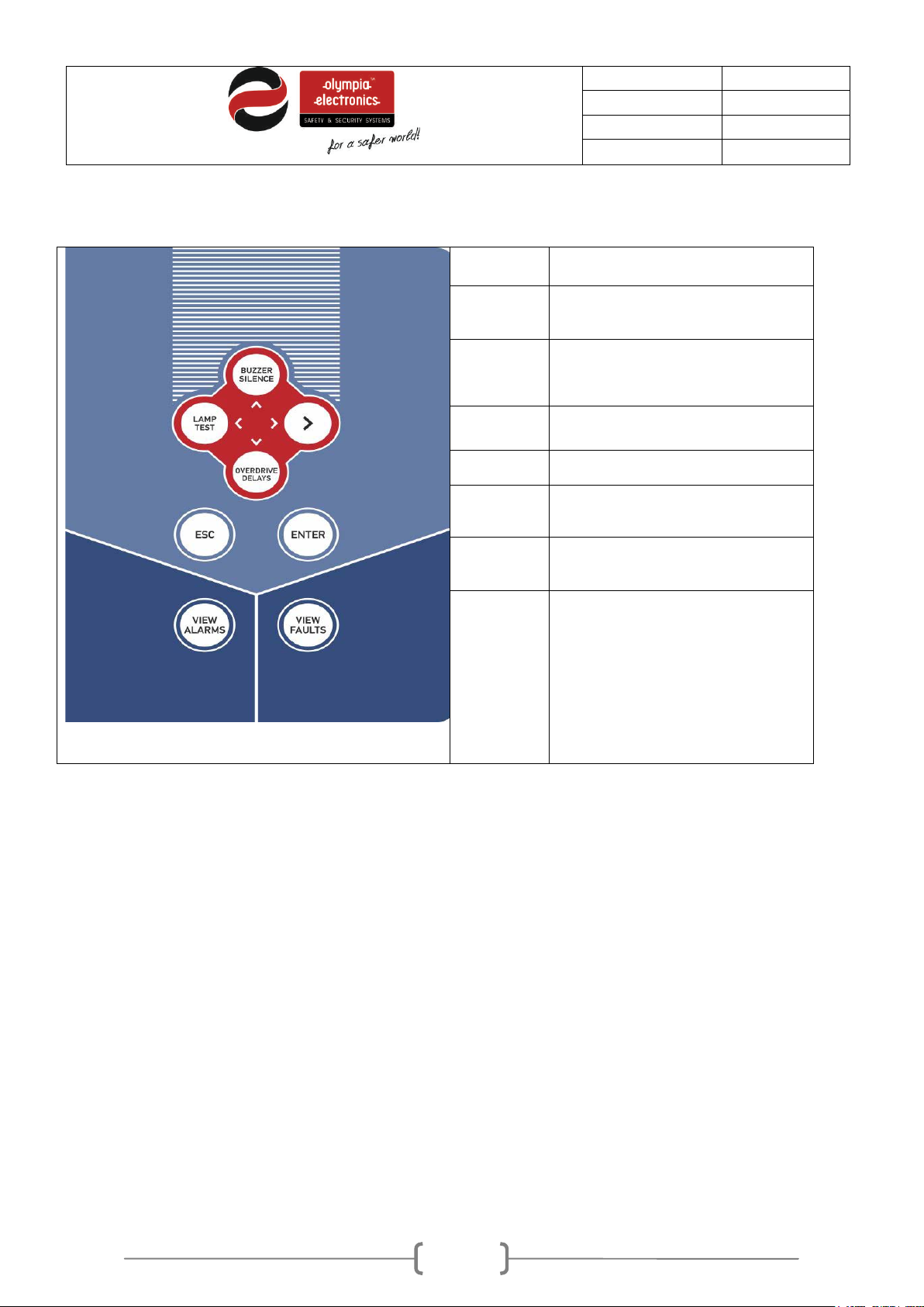
Buzzer
Use this button to conduct a lamp test. All
In case of an alarm when the delays are
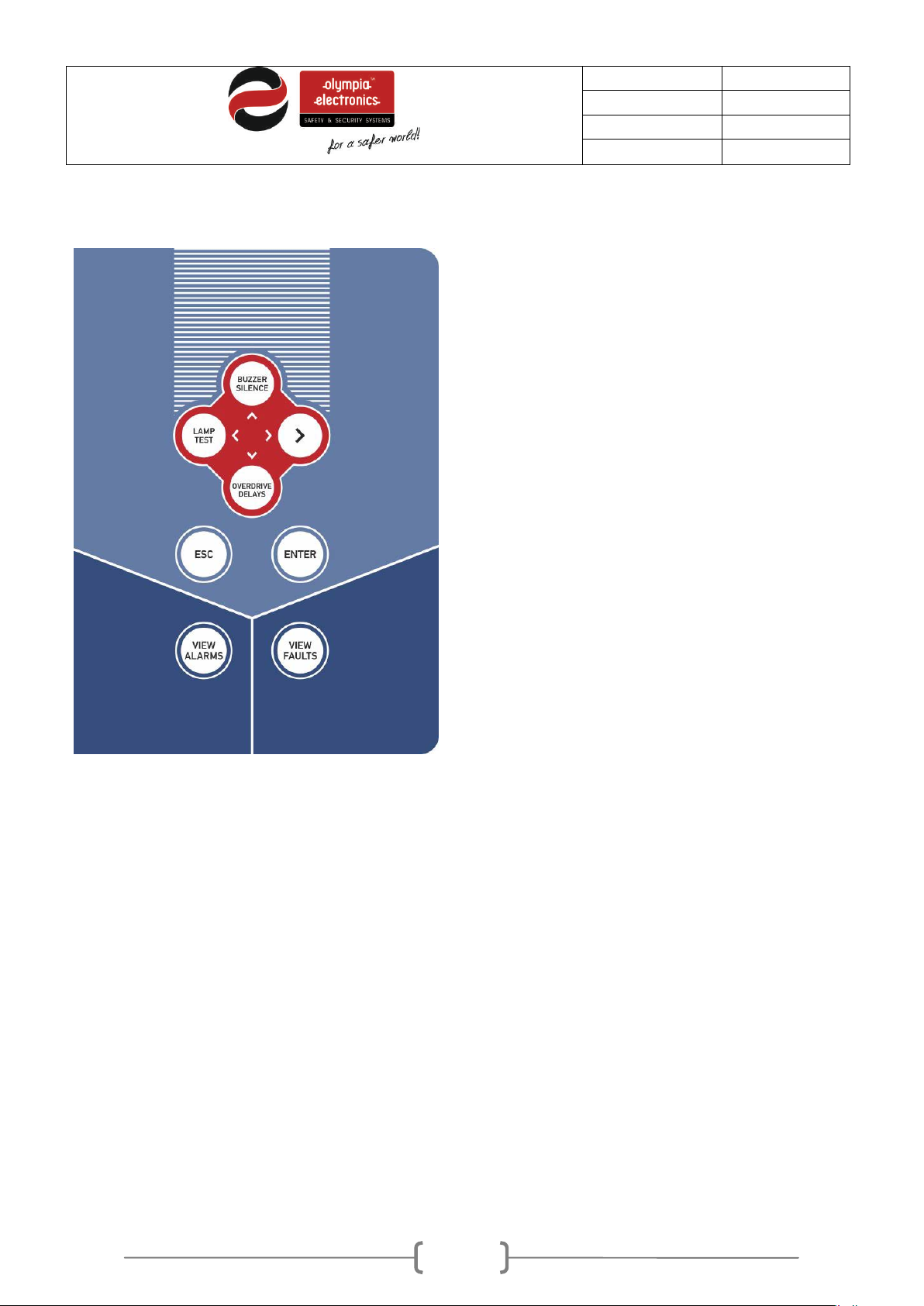
1.3.2 Keyboard of panel
Silence
Lamp Test
Overdrive
delays
Esc
Enter
View Alarms
View Faults
Arrow keys
Used to silence a sounding buzzer.
indicators and the screen are activated so
we can verify there correct operation.
enabled, the user can override the delays by
pressing this button. The output will be
activated immediately. (Access Level 2).
Exiting to the previous menu or Exit.
Confirming selection.
Showing current alarm (if they exist).
Showing current faults (if they exist).
Navigating in the menu (up / down / left /
right) – or moving the cursor.
Using the keys up or down we can increase
or decrease the value of the counter.
Figure 1-2. Keyboard of the panel
1.3.3 Indication LEDs
Page 7
7 / 47
Date
30/9/2016
File
Document code
921163800_09_007
Page
7 from 47
The system is in an alarm
Blinks when there is a
Blinks when there a fault
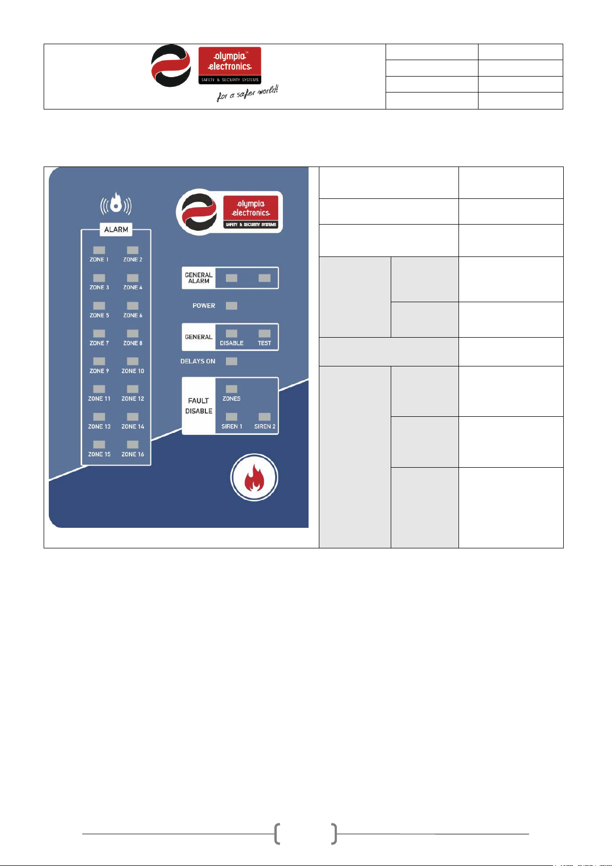
The LEDs are divided into groups and colorings so the indications are more comprehensive.
In detail, the indications of the LEDs correspond to the following case:
Alarm Zone [red]
General Alarm [red]
Power [green]
Disable
General
[yellow]
Test
DELAYS ON [yellow]
Zone
Fault –
Siren 1
Disable
Alarm in the
corresponding zone
state
General power indicator
of the panel.
General disable indicator
(disabled sections)
The system is in a test
state.
Active delays for the
outputs.
fault on the zone.
Always ON when the
zone is disabled.
on siren1.
Always ON when Siren 1
is disabled.
[yellow]
Blinks when there a fault
Siren 2
on Siren 2.
Always ON when Siren 2
is disabled
Figure 1-3. Indication LEDs
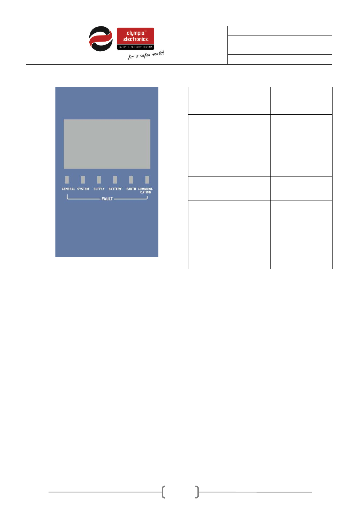
The following figure shows the indicators that are below the LCD screen. All of these indicators are
yellow.
Page 8
8 / 47
Date
30/9/2016
File
Document code
921163800_09_007
Page
8 from 47
Figure 1-4. Indicators below the LCD screen
General Fault
System Fault
Supply Fault
Battery fault
Earth fault
Communication fault
General fault of the panel
System fault
Power supply fault
Battery fault
Power Earth fault
Communication fault
2 Functions
2.1 Operation states of the panel
Below we will describe in brief the indications on the screen for the following states of the panel:
Α) Normal operation – quiescent state
Β) Alarm state
C) Fault state
Normal operation - quiescent state
2.2
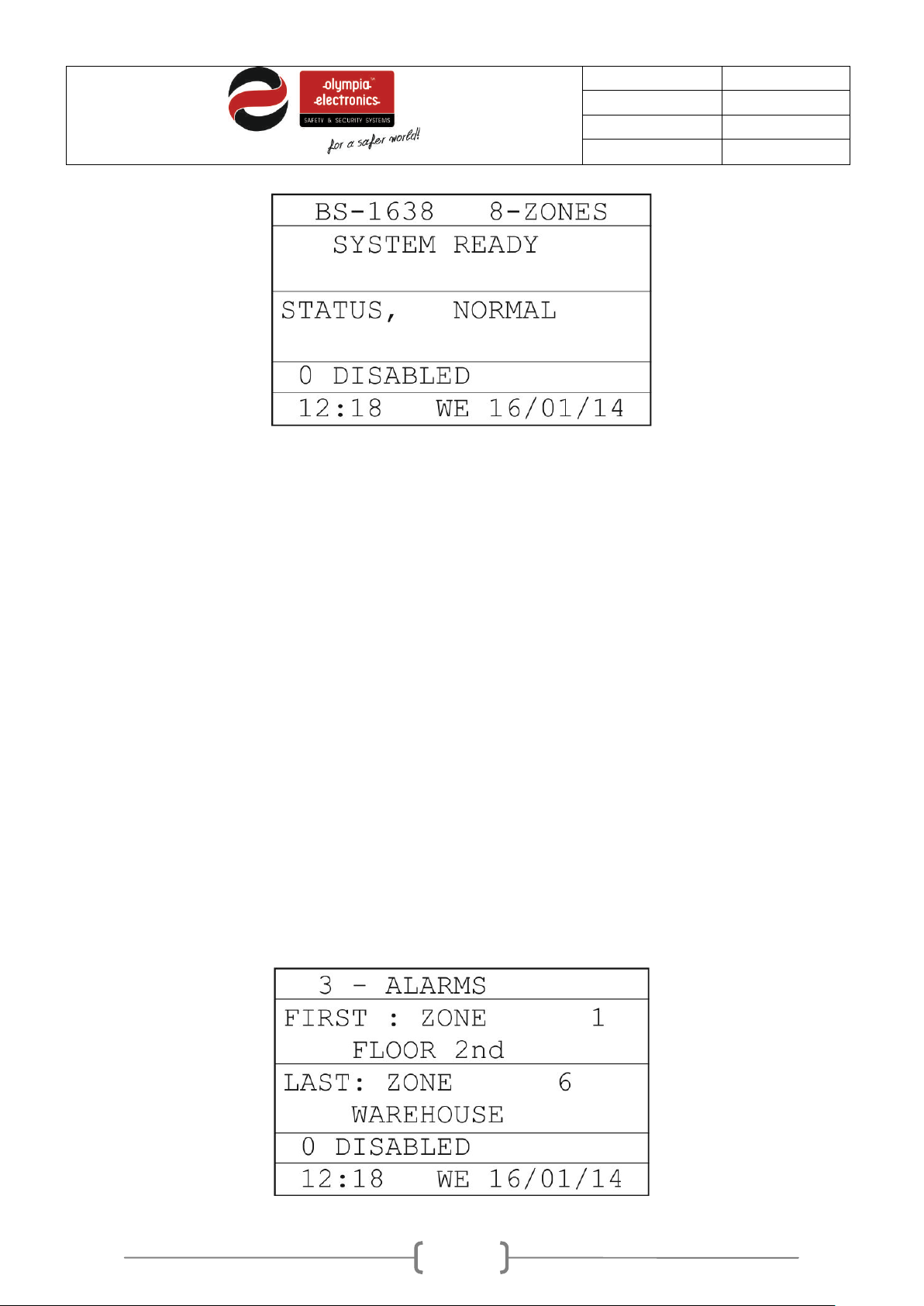
When there is no alarm or fault event the panel is in normal operation or quiescent state. The main
screen has the following indications:
Page 9
9 / 47
Date
30/9/2016
File
Document code
921163800_09_007
Page
9 from 47
Figure 2-5. System in normal operation – quiescent state
The first line shows how many zones the system has. It can be 8, 12 or 16 zones.
The last but one line shows the following messages in sequence:
• How many zones are «IN TEST»
• How many «FAULTS»
• How many sections are «DISABLED»
Only the POWER LED should be lit.
Notice. If there are any disabled sections then the corresponding LED will be lit and the screen will show
«DISABLED»
Alarm State
2.3
When a device issues a fire alarm the red LED “General Alarm” is lit . The display will show informat ion
concerning the origin of the alarm as shown below:
Page 10
10 / 47
Date
30/9/2016
File
Document code
921163800_09_007
Page
10 from 47
Figure 2-6. Typical indication during an alarm
The first line shows how many alarms exist on the panel. The next line shows the first alarm that
happened and specifically the zone and the name of the zone. The next line shows the last alarm that
was issued with the corresponding information.
When an alarm is issued all the corresponding elements that are connected with the alarm will be
activated. The built-in buzzer will start to sound in t ermit tently. If we want to stop the buzzer we can press
the key “Buzzer Silence” and if we want to stop the sirens we must g o to the menu and press «Siren
Silence».
Pressing the key ”VIEW ALARMS” will show all existing alarms.
2.4
Fault state
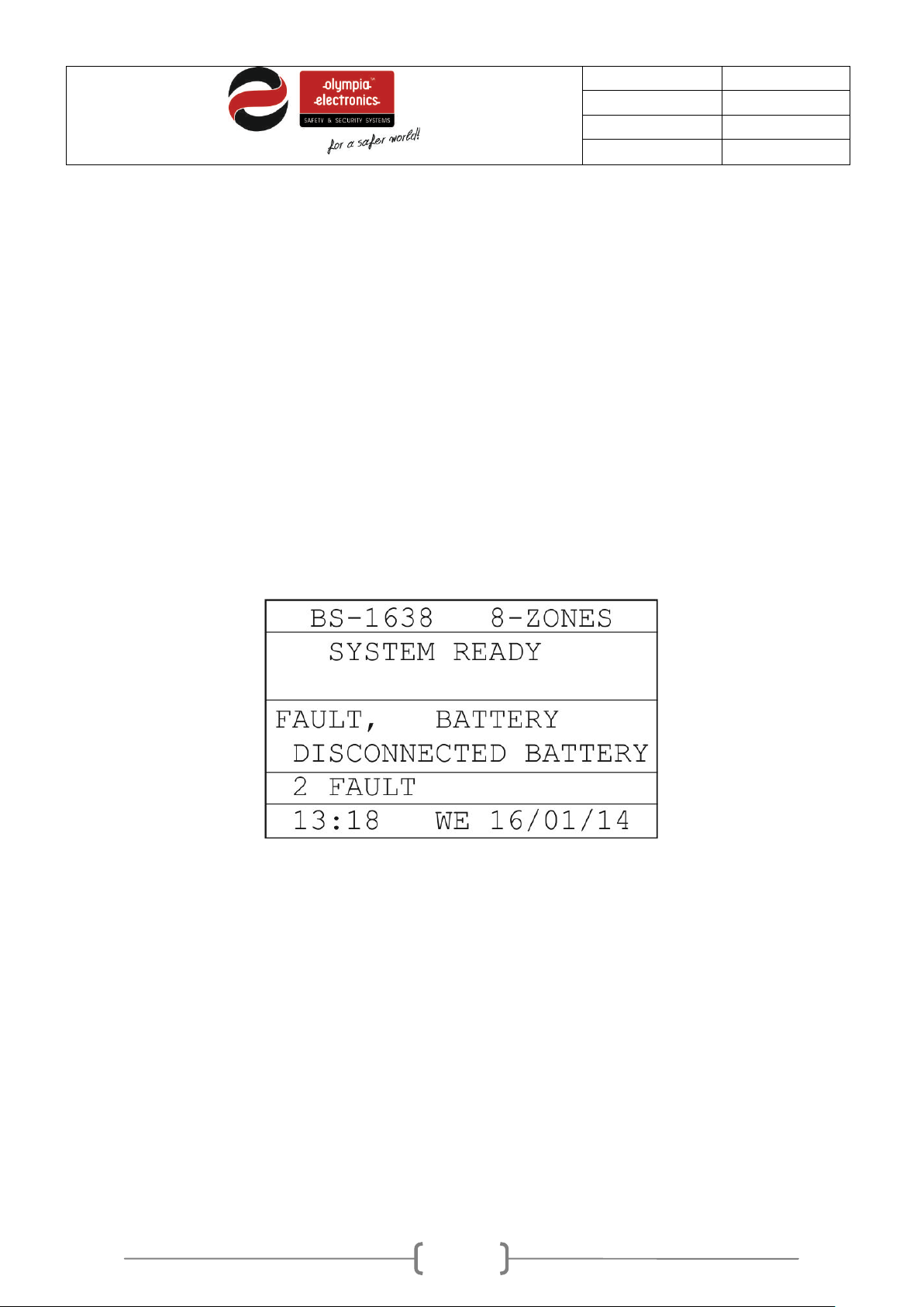
In case of a fault state the yellow LED marked “General Fault” lights. Simultaneously other LEDs can
be lit that describe the origin of the fault. The screen will show addition information regarding the fault.
Figure 2-7. A typical screen during a fault state
The third section of the screen shows in sequence the faults of the system . T he corresponding LED also
lights to show the fault.
When a fault condition is encountered then the internal buzzer sound continuously and all the elements
connected with the fault are activated. If we require we can stop the buzzer by pressing the key “Buzzer
Silence”.
Page 11
11 / 47
Date
30/9/2016
File
Document code
921163800_09_007
Page
11 from 47
- “Buzzer Silence”: In case of an
the user can override these delays by
to this in detail in the next paragraph.
Access Level 1 functions
2.5
This access level contains the functions that can be set by a normal user
alarm or fault, if this key is pressed then
the internal buzzer stops. As long as the
event exists the buzzer will sound once
every 30 seconds. If during this state a
new event happens then the buzzer will
start to sound again.
- “LAMP TEST”: When the panel is in
the normal-quiescent state then if we
press this button the panel will light all the
leds and the screen so we can verify the
good operation.
- “OVERDRIVE DELAYS”: If an alarm
event occurs and there are active delays,
Σ ΣΣ μ Σ 2-8. ΣΣΣΣΣΣΣΣΣΣΣ ΣπΣπΣΣΣΣ πΣΣΣΣΣΣΣΣ 1
2.6
Basic menu for Access Level 1
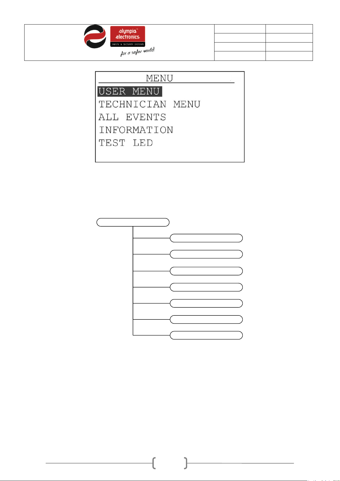
When the main screen is shown and we press the “ENTER” key then we are presented with the main
selection menu. The screen shows the following.
pressing this button. The output will be
activated immediately.
-
- “VIEW ALARMS”: In case of an
alarm event, if this key is pressed then we
are presented with a menu from which we
can see all the current alarms. We will
refer to this in detail in the next
paragraph.
- “VIEW FAULTS”: In case of a fault
event, if this key is pressed then we are
presented with a menu from which we
can see all the current faults. We will refer
Page 12
12 / 47
Date
30/9/2016
File
Document code
921163800_09_007
Page
12 from 47
MENU
USER MENU
TECHNICIAN MENU
INFORMATION
ALL EVENTS
CURRENT ALARMS
CURRENT FAUILTS
LAMP TEST
Figure 2-9. Main screen
As we can see, there are 7 basic functions in this menu as show in the diagram of figure 2-6.
The functions “CURRENT ALARMS” and “CURRENT FAULTS” are only shown when the panel has
registered such events
In detail:
• CURRENT ALARMS : This selection is shown only when the panel has registered an alarm
Figure 2-10. Menu diagram.
event. Selecting this option will show in detail all the current alarm events.
CURRENT FAULTS : This selection is shown only when the panel has registered a fault event.
Selecting this option will show in detail all the current fault events.
Page 13
13 / 47
Date
30/9/2016
File
Document code
921163800_09_007
Page
13 from 47
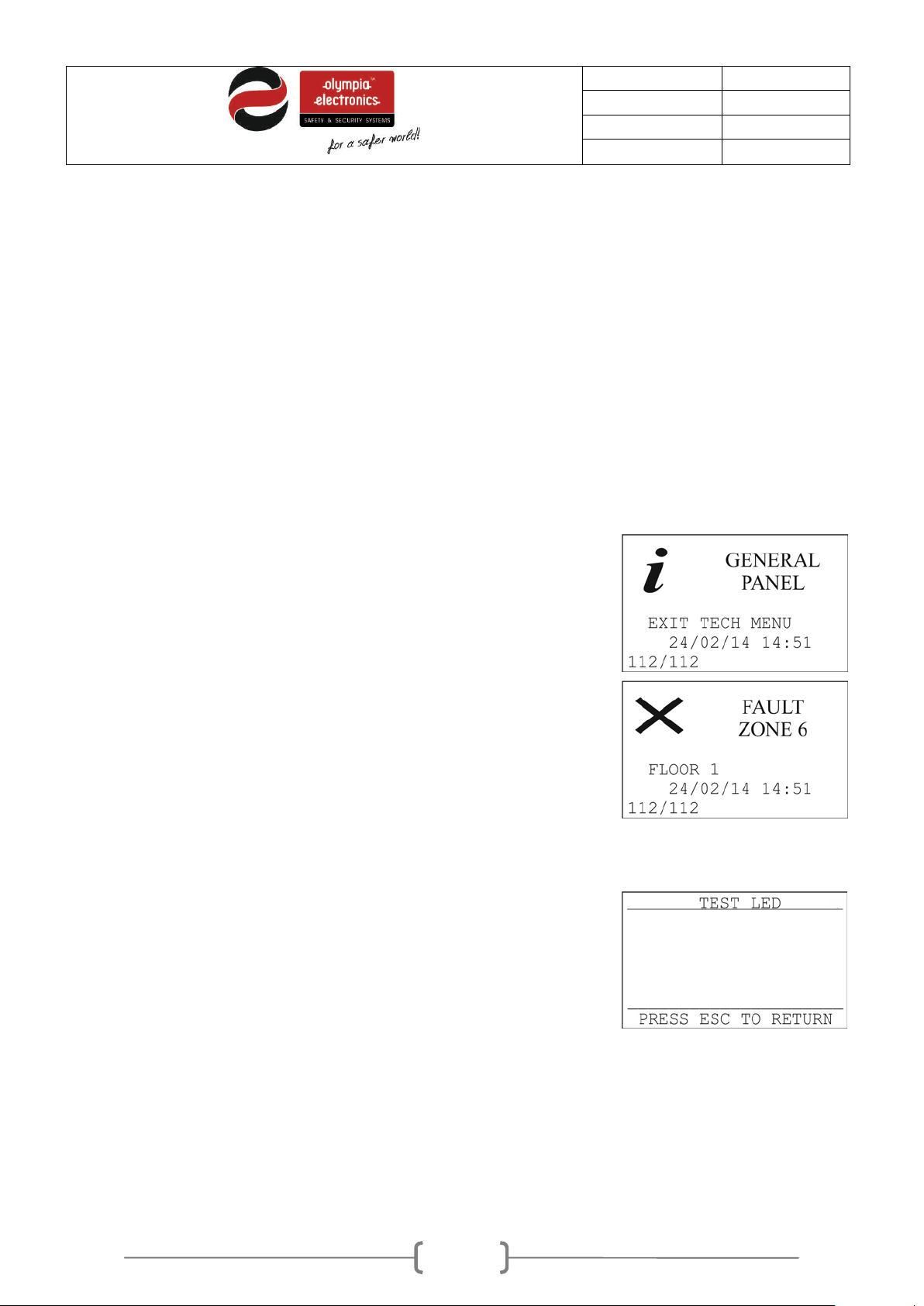
If we select the ALL EVENTS option and press the ENTER key then we will
i
• USER MENU : This menu contains all the functions the can be selected by a user that has
access level 2 clearance.
• TECHNICIAN MENU : This selection can only be selected by the technician and contains the
panels programming functions.
• ALL EVENTS : In this selection we can see all the events of the panel.
• INFORMATION : This selection contains information of the system that can be accessed by
every user.
• TEST LED : All the indicators are lit. It is identical in operation as the «LAMP TEST» key.
To select a function use the «UP» and «DOWN» keys and then press «ENTER».
2.6.1 Events Menu
see the adjacent screen. The first screen shows information that was
recorded and the second screen shown faults.
On all screens that contain information we can s ee a
Next to this on the right we can see the source of the event (in our case
GENERAL PANEL. Below this there is a detailed description of the event and
then the time and date. T h e last line s ho ws the cur ren t e vent n um ber as well
as the total events recorded.
On fault scree ns we ca n see an
see the source of the fault (in our case Zone 6). The next line shows the
name of the zone followed by the date and time. The last line shows the
current fault number as well as the total number of recorder faults.
With the up and do wn k e ys we c an s c rol l t hrough all the events. Pres s in g the
ESC key will takes us back to the previous menu.
Χ on the t op left c orner. Next to this we can
on the top lef t corner.
2.6.2 Test Led
If we select TEST LED and press ENTER we will see the adjacent screen. All
the LEDs will be lit so we can ver ify the good operatio n. Press ESC to go to
the previous menu.
Figure 2-11. Events Menu
Figure 2-12. LED test
2.7 Information
Page 14
14 / 47
Date
30/9/2016
File
Document code
921163800_09_007
Page
14 from 47
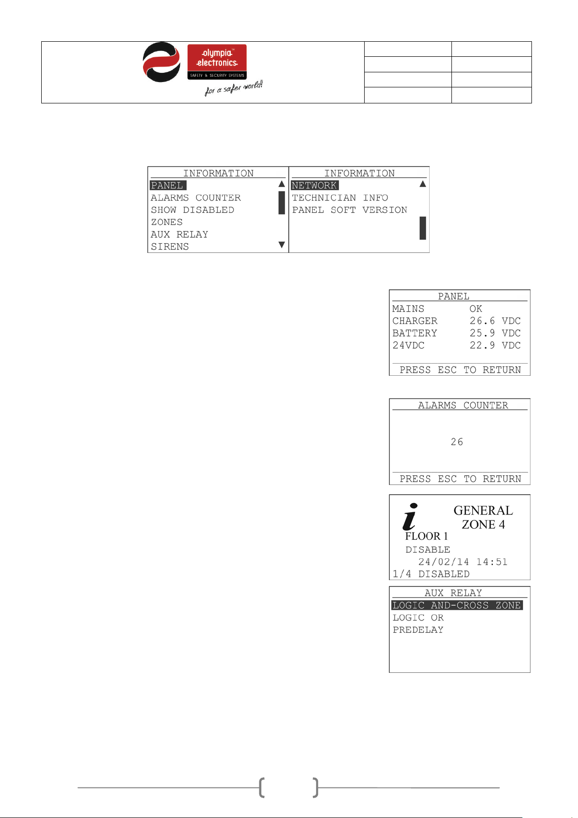
If we select PANEL we can see inform ation regarding the po wer supply and
The ALARMS COUNTER option shows an alarm count which is according to
You can see disabled section by selecting the option SHOW DISABLED. Use
By selecting the AUX RELAY option we are presented will the following
By selecting the INFORMATION option we can s ee the following scr een. Some option can’t be seen in the initial
screen and we must user the up and down keys to scroll to them.
Figure 2-13. Information menu
the battery.
ΕΝ 54-2.
the UP and DOWN keys to show all disabled sections.
menu.
Page 15
15 / 47
Date
30/9/2016
File
Document code
921163800_09_007
Page
15 from 47
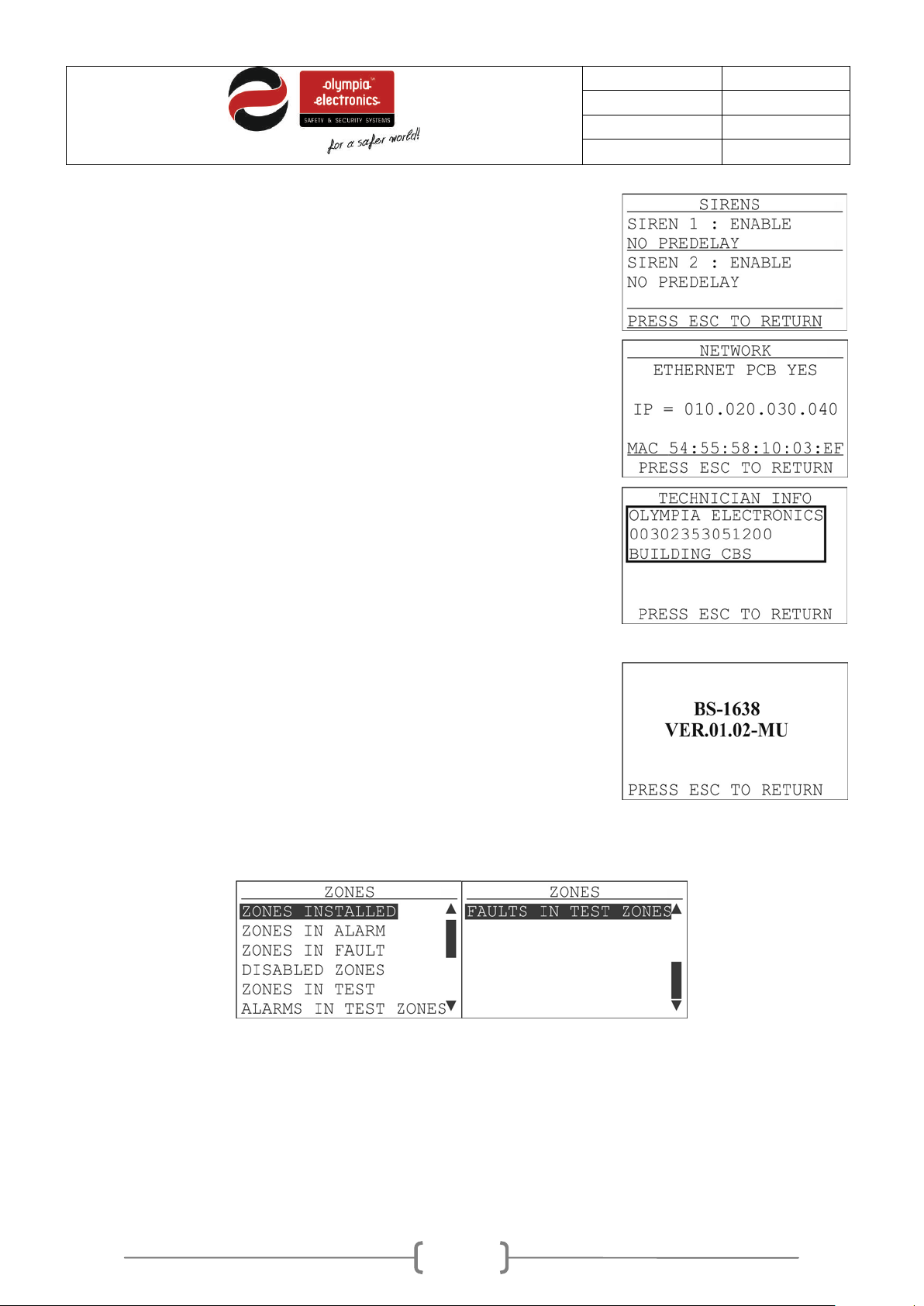
The option «SIRENS» reveals the setting of the 2 sirens.
If we select NETW ORK and press ENTER we can s ee the adjacent screen .
By selecting the TECHNICIAN INFO we can see the adjacent screen. By
If we select PANEL SOFT VERSION we can see the installed panel firmware
This screen shows if the E thernet card is installed. If it is installed then we
can see its IP and MAC address. Press the ESC key to return to the
INFORMATION MENU.
default we see that the te chnician information has Olympia electr onics, the
phone number and the ins talled site nam e. This infor mation can be cha nged
by using a P/C.
Press ESC to return to the INFORMATION menu.
version.
Press ESC to return to the INFORMATION menu.
2.7.1 Zone Information
In the zones information menu we can see the following options:
Figure 2-14. Zone information.
Page 16
16 / 47
Date
30/9/2016
File
Document code
921163800_09_007
Page
16 from 47
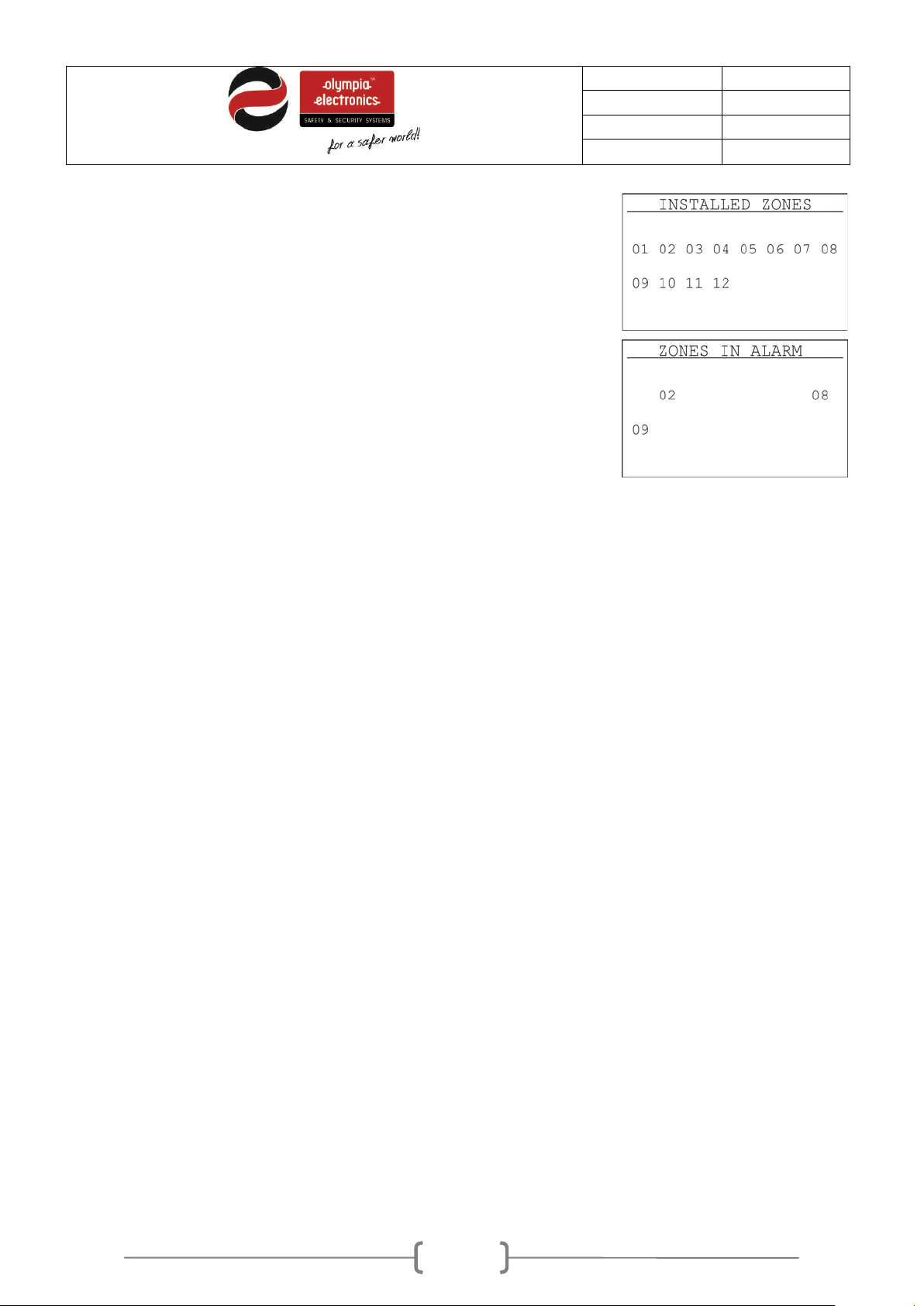
In the option ZONES INSTALLED we can s ee how m any zones are ins talled
In the selections «ZONES IN ALARM» and «ZONES IN FAULT» we can see
Finally, the last three options we can see which zones are in test mode,
in the panel. E.g. BS-1638 has 8 zones, BS-1642 has 12 zones.
which zones have an alarm and which have a f ault respec tively. The number
of the zone blinks.
which are in test m ode and have an alarm and whic h are in test mode and
have a fault.
Page 17
17 / 47
Date
30/9/2016
File
Document code
921163800_09_007
Page
17 from 47
3 User Menu
In this section we will refer to the selection that can be done by a user (access level 2).
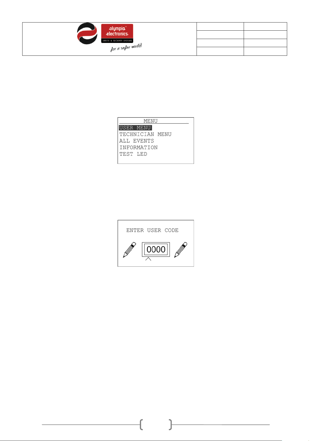
To enter the menu of the panel press «ENTER» and the display will show (figure 3-1).
Figure 3-15. Main menu
Next select the «USER MENU» option with the use of the keys «DOWN» and «UP».
To enter access level 2 a code is required.
Figure 3-16. User code
Enter the user code using the up and down keys to change the value of the digit. Use the left and right
keys to move to the next or previous digit. When the code has been entered press the ENTER key to
accept.
The factory default code is «1111».
Page 18
18 / 47
Date
30/9/2016
File
Document code
921163800_09_007
Page
18 from 47
USER
ENABLE
DISABLE
DATE/TIME
ALL ZONES
ZONE
SIREN 1
ALL ZONES
ZONE
SIREN 1
TIME ADJUST
DATE ADJUST
DAY ADJUST
RESET SYSTEM
SIREN SILENCE
EVACUATE
DELAYS
CODE USER
SIREN RESOUND
ENABLE
DISABLE
SIREN 2
SIREN 2
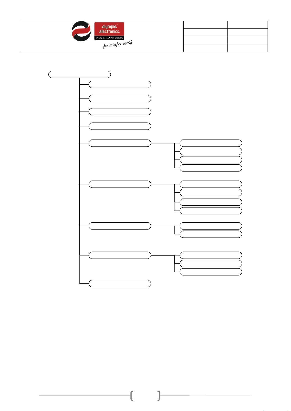
Figure 3-3 shows the tree diagram of this menu.
Figure 3-17. User menu tree diagram
In this menu we can do the following basic functions.
• RESET of the system.
• SIREN SILENCE in case of an alarm.
• SIREN RESOUND in case of an alarm and if the sirens have been silenced.
• EVACUATE for the system to enter alarm mode.
Page 19
19 / 47
Date
30/9/2016
File
Document code
921163800_09_007
Page
19 from 47
3.1
Enable – Disable menu
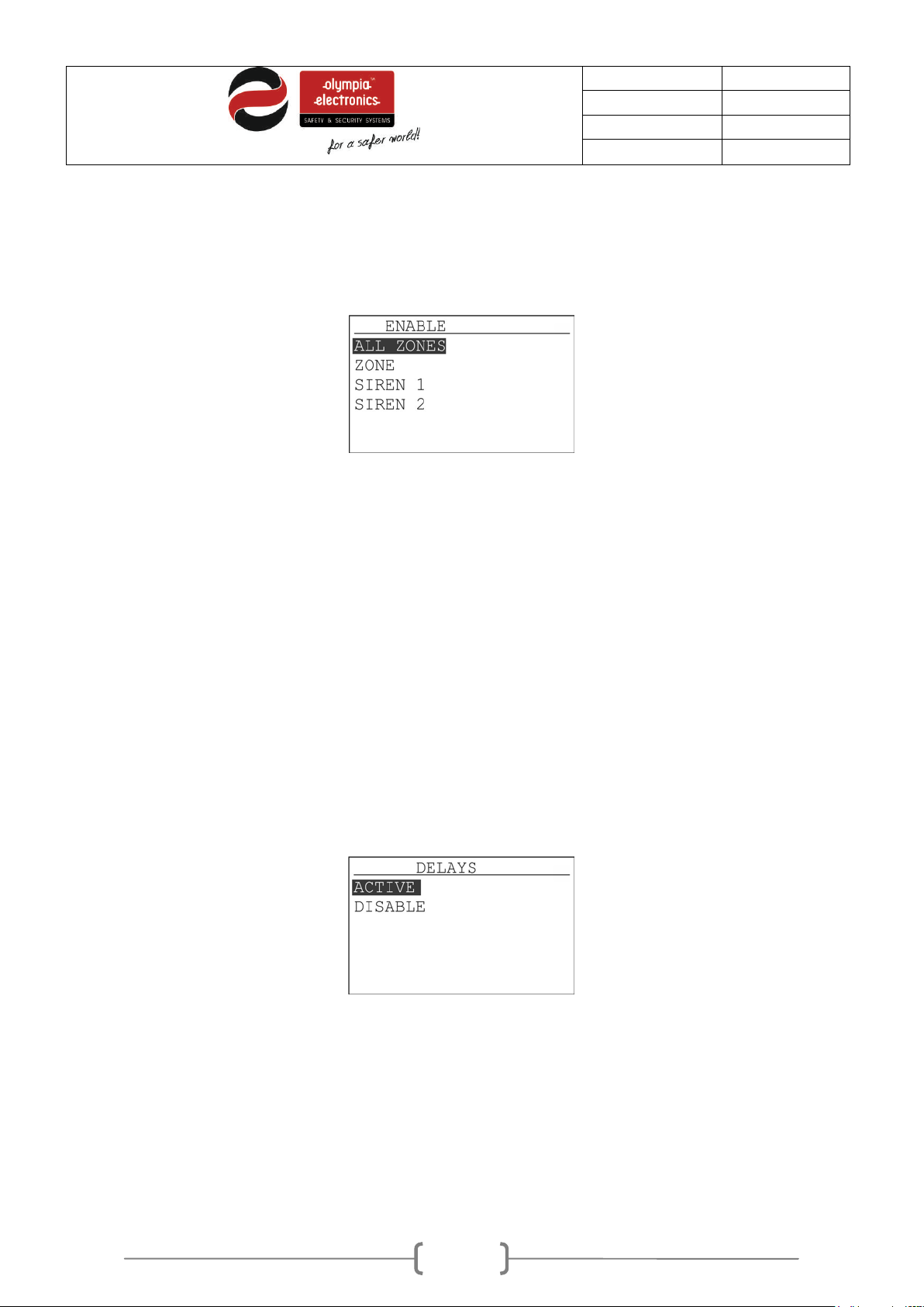
With the selection ENABLE we can activate any element of the panel as shown in figure 3-4.
Figure 3-18. Activate menu
We have the following selections:
• ALL ZONES : All elements of the panel are activated.
• ZONE : We select the zone that we want to activate (1 – 16 depending on the panel), with the
keys «UP» and «DOWN».
• SIREN 1 and SIREN 2: We can select which siren we want to activate.
Respectively in the «DISABLE», menu we have the same options but now we can deactivate the
elements.
Delay menu
3.2
Using this menu the user can activate or deactivate the time delays.
Figure 3-19. Delays menu
3.3
Adjusting the time and date
The user is this menu has the capability to adjust the following:
• ADJUST DAY : Set the day of the week.
• ADJUST DATE : Set the date.
• ADJUST HOUR : Set the hour.
Page 20
20 / 47
Date
30/9/2016
File
Document code
921163800_09_007
Page
20 from 47
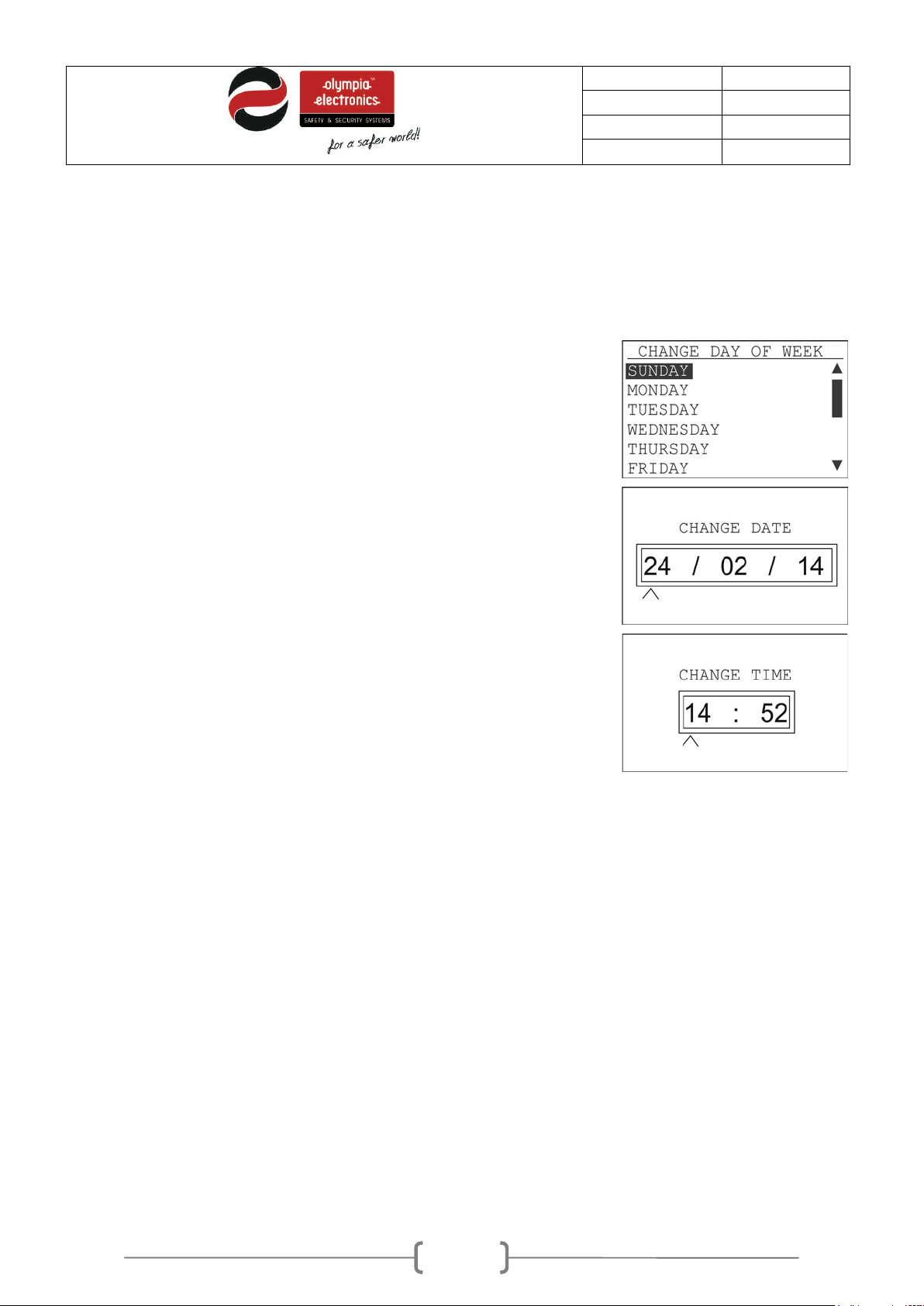
With the next 3 option we adjust the date and hour. It is critical to
we can see the adjacent
The first 3 option are use to adjust the hour, date and day will a simple manner. To change the values
use the navigation keys, UP, DOWN, LEFT, RIGHT. After selecting each value press the «ENTER» key.
adjust these setting during the initial installation because all events
are recorded using this time and date.
By selecting DAY OF WEEK SETTING and Enter we see the adjacent
screen. Select the required day and press Enter.
By selecting DATE SETTING and Enter we see the adjacent screen.
Use the up and down keys to change the value and the right, left keys
to go to the next or previous digits. After the desired date is entered
press the ENTER key.
By selecting TIME SETTING and Enter
screen. Use the up and down keys to change the value and the right,
left keys to go to the next or previous digit s. After the desired time is
entered press the ENTER key.
3.4
Changing the user code
The last option permits the user to change the user code. Use the up and down keys to change the value
and the right, left keys to go to the next or previous digit s. After the desired code is entered press the
ENTER key.
Page 21
21 / 47
Date
30/9/2016
File
Document code
921163800_09_007
Page
21 from 47
Use a P/C to access the user menu
3.5
The programming of the panel can be done using the panels own keyboard or by using a personal
computer. If we have a network of panels then some options can only be done using a computer.
3.5.1 Using a personal computer
To program the panel using the P/C no special software is required. A common web browser (Chrome,
Firefox, Internet Explorer κ.λ.π), can be used. W e suggest Google Chrome. The following screens are
from Google Chrome. Prerequisites are that the panels must have an Ethernet card installed, we must
know the IP address of the panel, the P/C must be connected to the same network as the panel and the
network setting of the P/C must be correct. W ith suitable settings we can have access to the panel via
internet from what every part of the world we require. All these settings must be adjusted by the network
manager of the building.
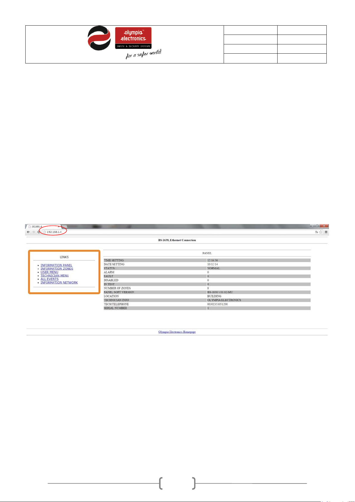
Our first action is to open a web browser and in the URL address line we must enter the IP address of
the panel. If all is connected correctly then we will see the following screen.
The pre-installed IP is 10.0.1.149.
On the right we can see information of the system and its operation state.
All the functions in the section“LINΚS” on the left are available to the user. The TECHNICIAN MENU is
not available.
Page 22
22 / 47
Date
30/9/2016
File
Document code
921163800_09_007
Page
22 from 47
3.5.2 Panel information
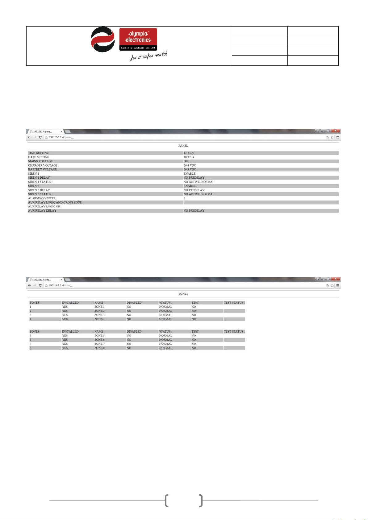
By selecting «INFORMATION PANEL» we can see the screen below which shows the state of the panel,
information about the sirens and the auxiliary relay.
3.5.3 Zone Information
This screen shows how each zone has been programmed to operate.
Page 23
23 / 47
Date
30/9/2016
File
Document code
921163800_09_007
Page
23 from 47
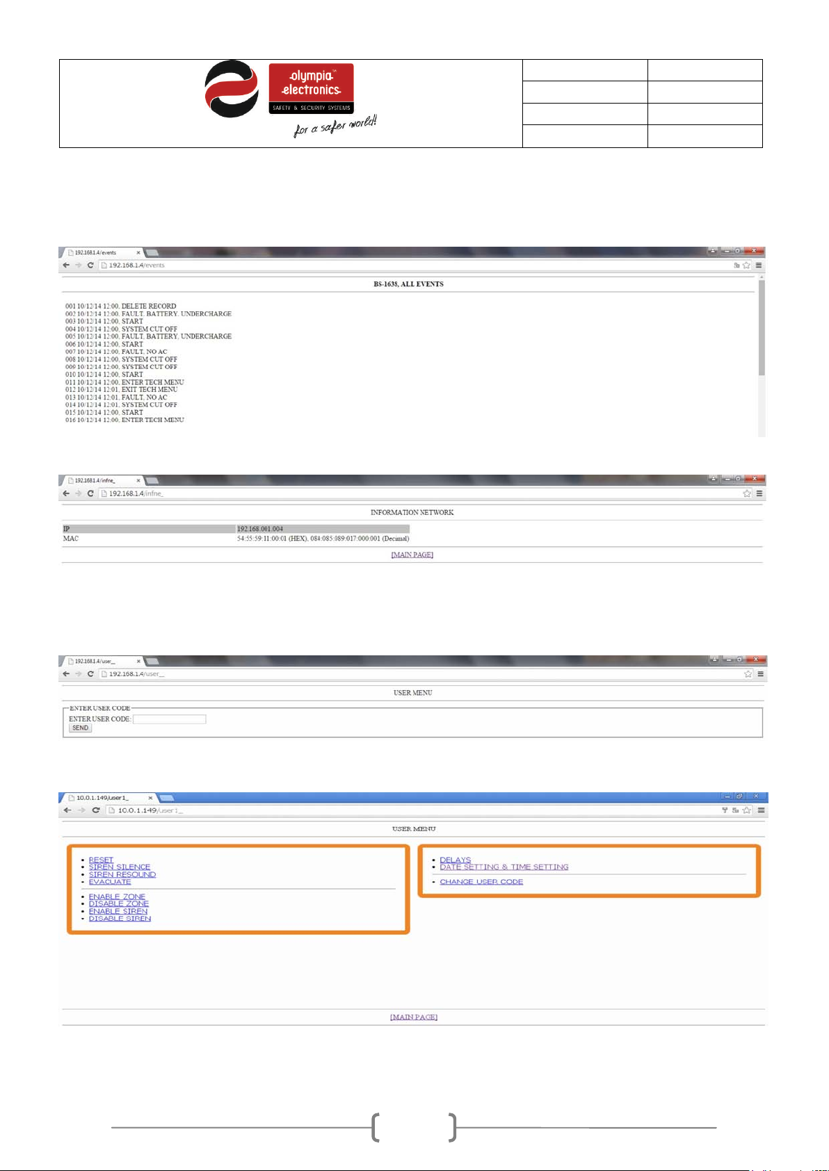
3.5.4 All events
The selection shows the events of the system in chronological succession.
3.5.5 Network Information
We can see the IP and MAC address of the panel
3.5.6 User Menu
By selecting USER MENU we see:
Place the cursors in the field “USER CO DE”, enter the user code and press SEND. If the code is correct
the user menu is shown.
Its operation and functions are identical as in the panel.
Page 24

24 / 47
Date
30/9/2016
File
Document code
921163800_09_007
Page
24 from 47
4 Installation
This section contains information that regards the design of the installation, the connection of the panel
with its peripherals and all the auxiliary inputs and outputs. The complete knowledge of the panel’s
capabilities and its peripheral devices is required for a good installation.
All connection described below must be done with the mains power supply isolated and the
battery cables disconnected.
4.1
Safety
A device cannot be considered that it is used correctly if you do not read the accompanying
documents that are supplied.
This product must be installed, commissioned and serviced only by qualified and trained personnel
according to:
The regulations concerning the installation of electrical devise in a building.
The fire saf ety regulations .
The instructions of the manufacturer.
- The product operates with a voltage of 220-240V ΑC/50-60Hz and is a class 1 unit. (For safety and
operation reasons it requires that the power earth cable of the building is connected).
- It must be installed to the current electrical installation using a dedicated fuse with a label «Fie
detections system – Do not close the switch».
4.2 Installation
The installation of the panel must be done only by qualified personnel only.
Prior to any maintenance procedures isolate the mains power supply from the panel.
Do not remove or install boards with the mains power active.
During the installation use an anti-static protection wristband to protect the panel from electrostatic
discharge (ESD).
The panel must be permanently mounted.
Page 25
25 / 47
Date
30/9/2016
File
Document code
921163800_09_007
Page
25 from 47
2
2
0
-
2
4
0
V
A
C
L
N
4.2.1 Mounting the panel on the wall
The packaging contains: The panel, the mounting accessories and the user manual.
The package also contains the keys for the front cover lid lock.
The panel must be mounted on a dry and clean sturdy wall that is free from vibrations and shocks.
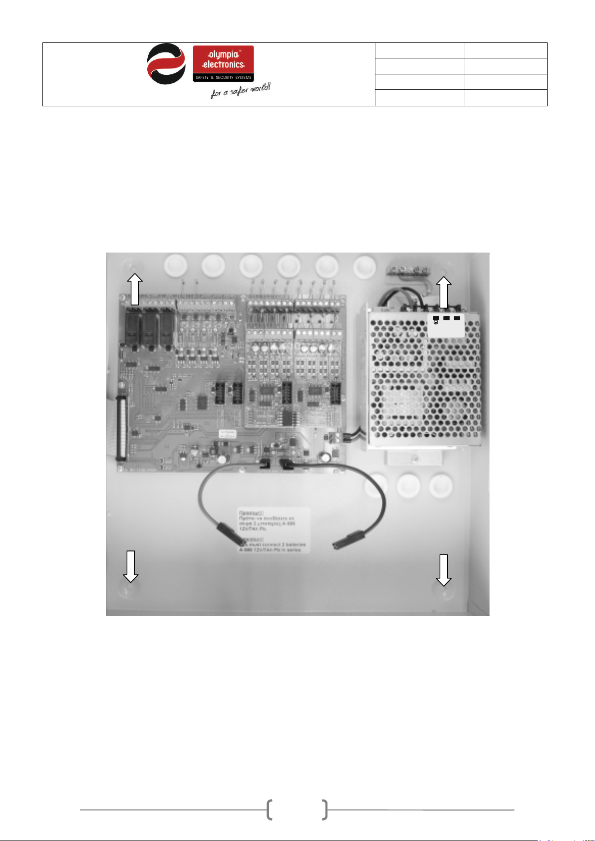
The image below shows the mounting holes of the panel.
The panel must be mounted at least 1m from floor level and at least 1m from the ceiling and about 30cm
from surrounding objects. No other power lines should pass behind the panel apart from its own.
Mounting the panel to the wall it done via the 4 mountings holes and by using the provided mounting
accessories.
The panel should be mounted in a clearly visible and accessible site t hat can be easily accessed by the
person responsible for the fire detection system. The panel is suitable for wall mounting installations in
interior areas.
Figure 4-20. Mounting hole locations.
Page 26
26 / 47
Date
30/9/2016
File
Document code
921163800_09_007
Page
26 from 47
Cable length
100mA
1.0 mm2
1.0 mm2
2.0 mm2
2.5 mm2
2.5 mm2
250mA
1.0 mm2
1.5 mm2
2.5 mm2
2.5 mm2
2.5 mm2
300mA
1.5 mm2
1.5 mm2
2.5 mm2
2.5 mm2
2.5 mm2
Cables
4.3
In order to comply with electromagnetic compatibility (EMC), the connection to the panel must be done
with shielded cable.
Each shield of the cable must be connected normally to the earth cable in order to assure the smallest
route.
The maximum cross section of the cable is 2,5mm².
The panel has numerous cable entry point located on the top and the rear. (see. figure 3.4).
The rubber grommets must not be removed in order to preserve the IP30 cover protection rating.
(required by the norm EN 54-2).
Each connection must have its own cable. For the connection of the zone or the siren a two core cable is
required whereas for the connection of the 230V power supply a three core cable is required.
All isolations and earths from the cables must be connected to the terminal connectors f ound on the left
of the panel.
The connection cables must be certified for fire detections installations. Such cables are FIP200,
MICC, PYROFIL.
The cables used for data must be twisted pair with and external shield.
The terminal block of the product can accept cables with a diameter up to 2.5mm. All terminal must be
tight even if they do not have a connection.
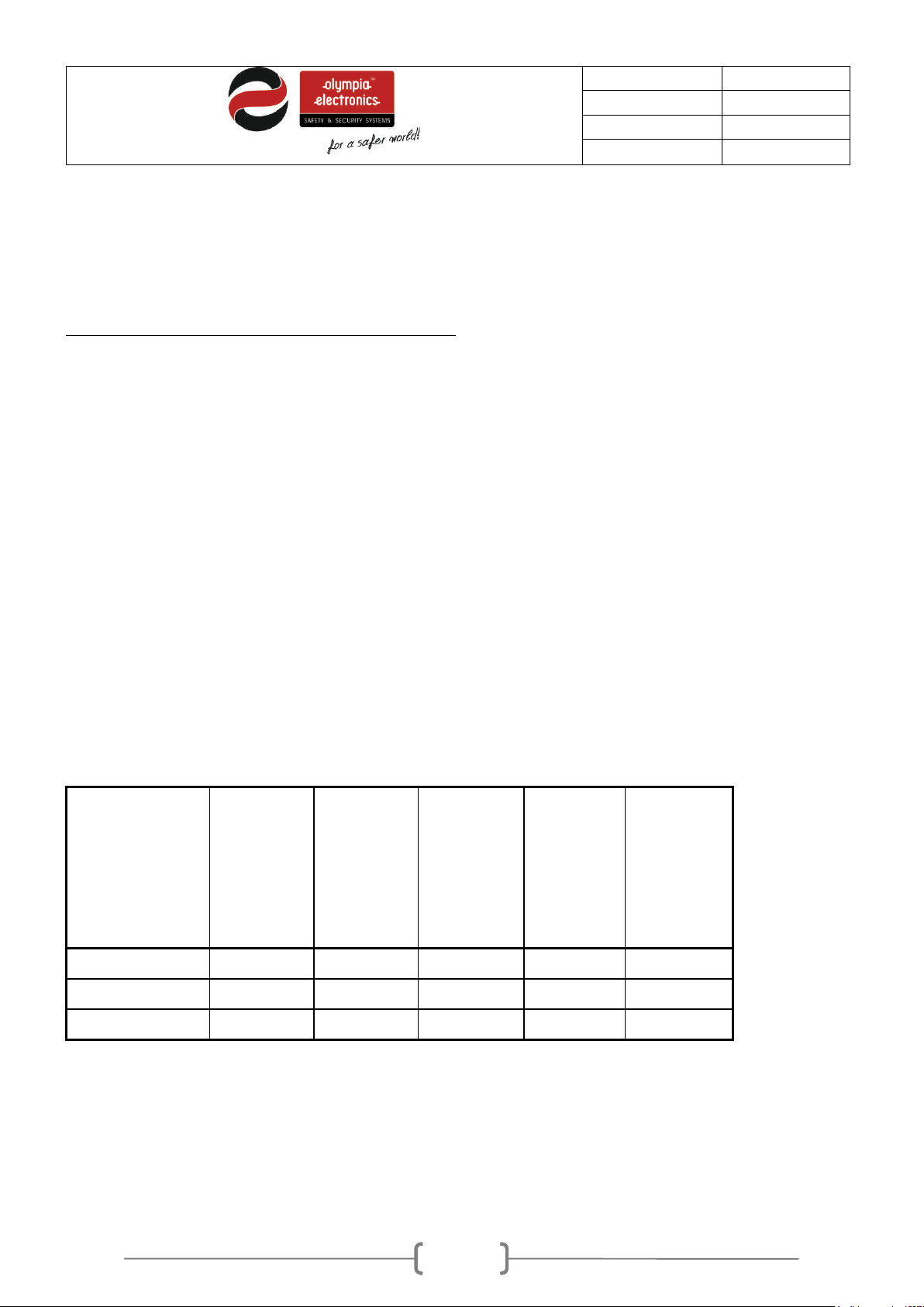
The diameter of the cable for conventional sirens is shown on the table below.
Table 4-1 Cable length for sirens (Alarm)
(m)
Alarm
Current
consumption(mA)
200m 500m 1000m 1500m 2000m
The main power connection of the panel must be connected to the main power supply using a separate
fuse with the marking «Fire Detection System – Do not close the switch». The f use rating must be
16Α.
The central power connection must have an earth cable that is connected to the main power earth
connection of the building.
Page 27
27 / 47
Date
30/9/2016
File
Document code
921163800_09_007
Page
27 from 47
2
2
0
-
2
4
0
V
A
C
L
N
Describing the interior of the panel
4.4
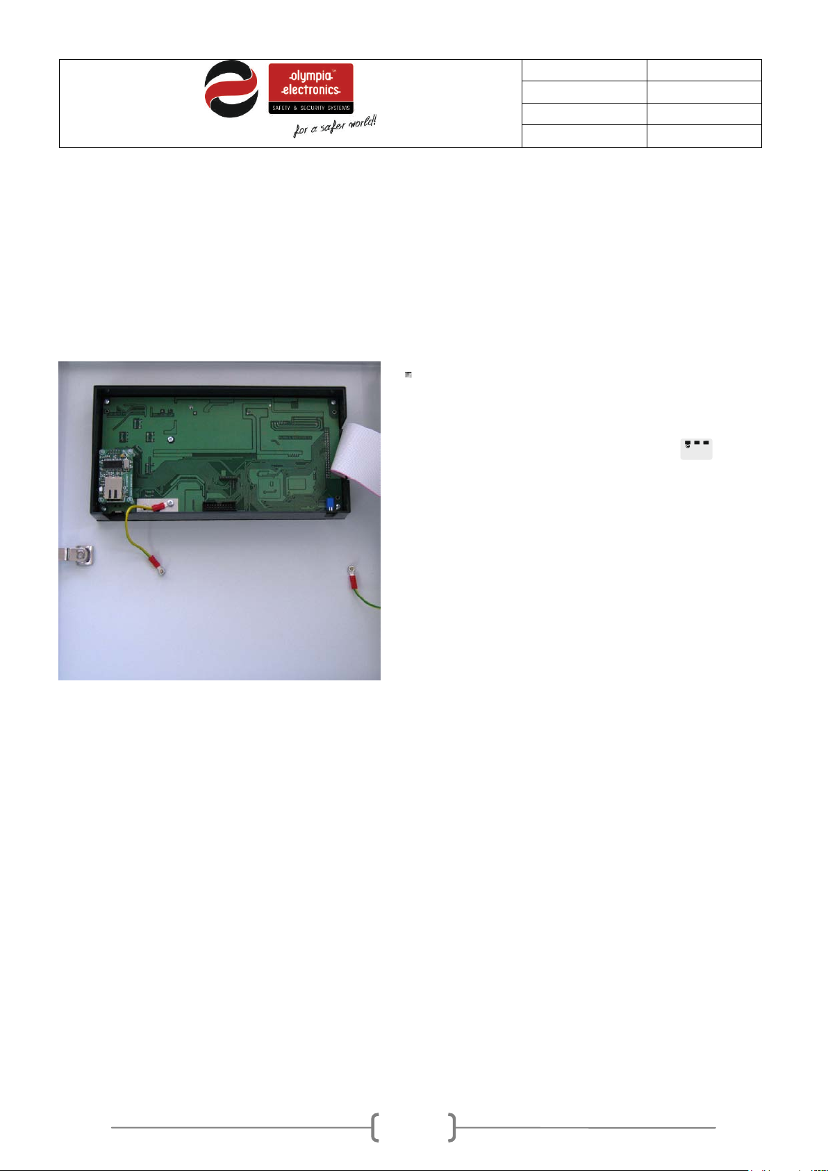
To access the interior of the panel we must open the lock on the front lid.
The BS-1638 panel main consists of two sections:
1. The left section which is the lid and contains the main pcb with the controller, the indication pcbs and
the lock.
2. The right section contains the power supply, the zone and input/output pcbs, the battery compartment
and the cable entry holes.
Figure 4-21. Panel Interior
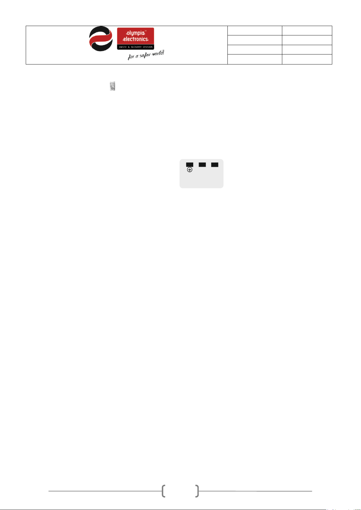
4.5 Connecting the power supply cables (220-240V AC)
The panel has cable entry holes for all the cables. You can connect cables with a maximum diameter of
2.5mm to the terminal blocks.
The power supply cables of the panel must be with double insulation. The power supply cable must also
contain a power earth cable that must be connected to the main power earth connection of the building.
Page 28
28 / 47
Date
30/9/2016
File
Document code
921163800_09_007
Page
28 from 47
2
2
0
-
2
4
0
V
A
C
L
N
Warning.
1. Each installation and maintenance procedure must be done with the mains power supply isolated.
2. During the installation, the connection of the batteries and the power supply must be done after
completing the other connections.
3. The connection with the power supply must be done using a dedicated fuse with a rating of 16A.
4. Always use double insulated cables for the mains power supply.
5. The external cable diameter must be at least 1cm.
6. The external insulation of the cable must not be removed more than 1cm.
7. The external insulation must not be removed more the 1cm from the edge of the internal insulation.
8. The internal fuse rating of the panel is F 4A 250V of the type TR5.
Figure 4-22. Connecting the 230VAC
Page 29
29 / 47
Date
30/9/2016
File
Document code
921163800_09_007
Page
29 from 47
9. The battery fuse is 900mA and is self resetting.
4.6
Connecting the batteries.
The panel has space with suitable dimensions for installing batteries of the type Α-986 from olympia
electronics. The charging circuit has been adjusted for these specific batteries. Should the batteries need
replacing, replace them with the same type and rating.
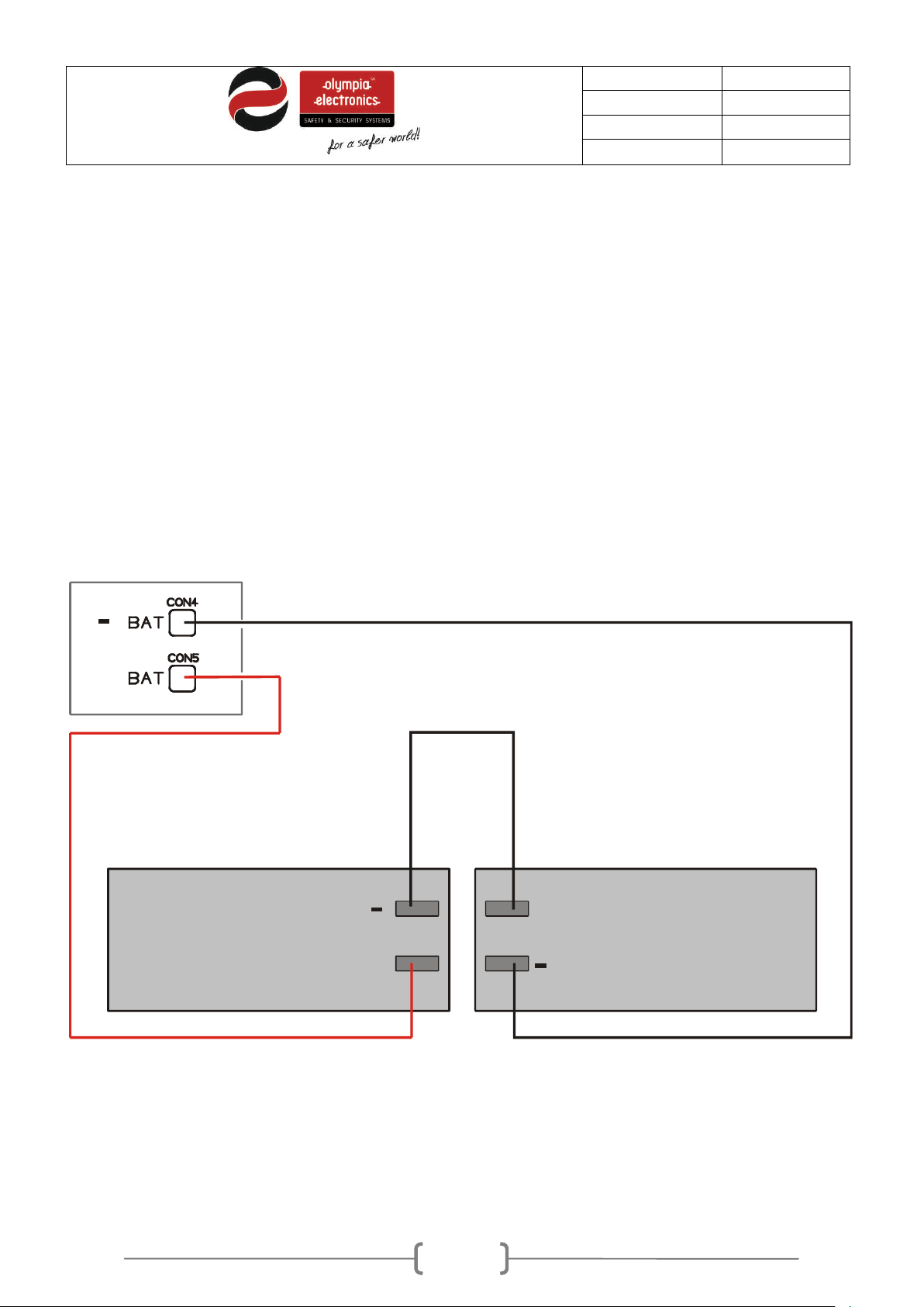
The batteries should be connected in series. The battery compartment contain two cables, one red and
one black, which are connect ed to the panel and one more cable that is not connected. T hese cables
must be connected in a specific order. The red cable must be connected to the positive contact (+ RED)
of the first battery. The black cable should be connected to the negative contact (- BLACK) of the second
battery. The third cable is used to connect the negative contact (- BLACK) of the first battery to the
positive contact (+ RED) of the second battery.
This connection is shown in the diagram below.
The batteries used should be 2x Α-986 12V (7Ah) lead acid type with a voltage of 12V. There
capacity must be 7Ah or 9Αh (Α-961).
Battery Recycling. It is not allowed to dispose batteries in common waste bins. They should be
disposed only in special battery recycling collection points.
+
2 12
x V Battery - connection diagram
with loop board
+
Battery (1) Battery (2)
+
Figure 4-23. Connecting the batteries in series.
Page 30
30 / 47
Date
30/9/2016
File
Document code
921163800_09_007
Page
30 from 47
4.7
Connecting the Zones
The panels of this family have the same connections. The only diff erence they have is the number of t he
zones and the zone relays. The common outputs, the maximum consumptions and the connection
diagrams that will be mentioned below are common to all the panels.
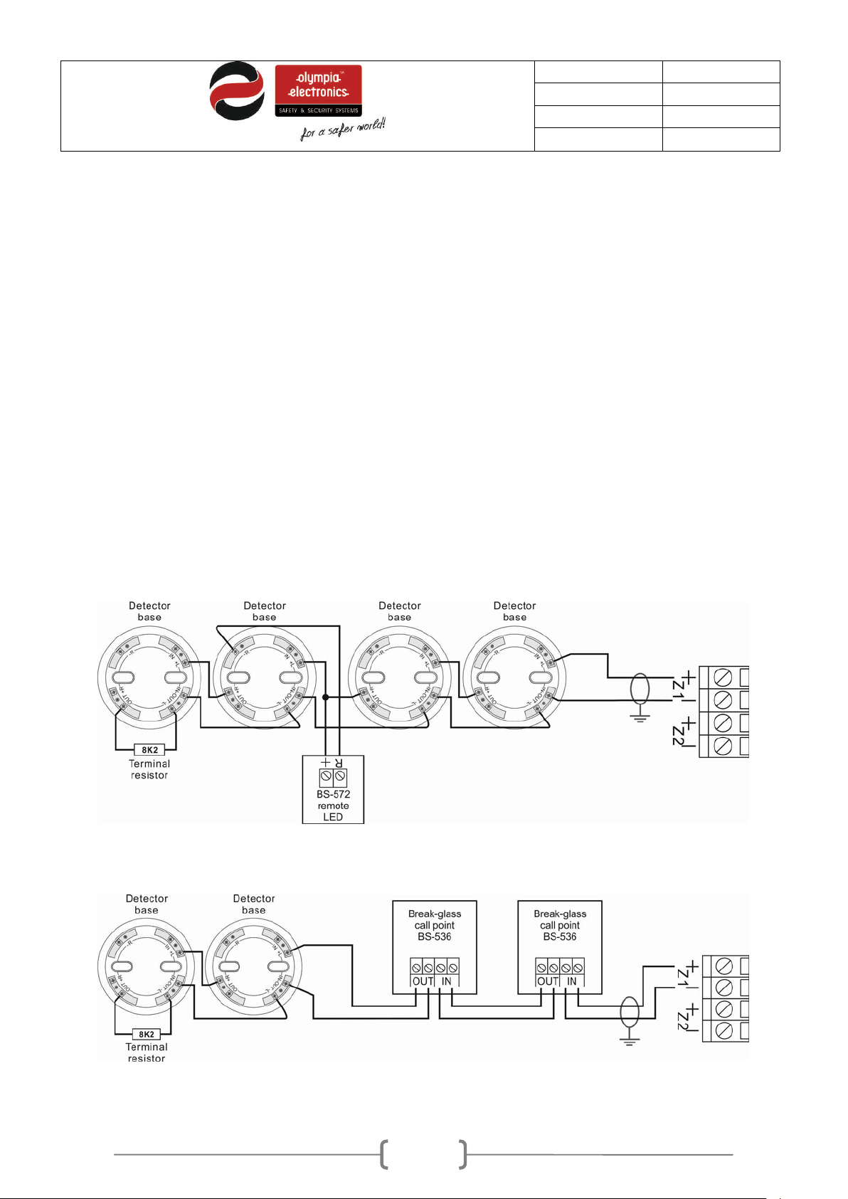
By default, the terminal block of each zone contains a (8Κ2) terminal resistor. The resistor must be
removed from the terminal block and installed on the last device of the zone or left connected on the
zones terminal block if the zone is not used.
The connections of all the zones are identical. W hat is shown on the next 3 diagrams for zone 1 is also
valid for the other zones.
Up to 20 devices (maximum) can be connected on each zone.
The shield of the cable that is used in the installation must be connected to the ground in order to
conform to the requirements of the electromagnetic com pa tibility norm (EMC).
The length of the cable must not exceed 2 km and the maximum diameter should not be more than
2mm².
Figure 4-24. Connecting 4 detector bases to zone 1. On each ba se you can install BS-655, BS-660 or BS-657 detectors.
On one detector there is a BS-572 detector LED connected.
Figure 4-25. Connecting 2 detector bases and 2 BS-536 call points to zone 1. On each base you can install BS-655, BS-
660 or BS-657 detectors.
Page 31
31 / 47
Date
30/9/2016
File
Document code
921163800_09_007
Page
31 from 47
8,2kΩ
8,2kΩ
AL2AL1
Sirens Sirens
Figure 4-26. Connecting 3 gas detectors BS-685 or BS-686. Apart from connecting the detectors to the zones, the
detectors must also be powered from the terminals 24V_M.
4.8
Connecting the Sirens
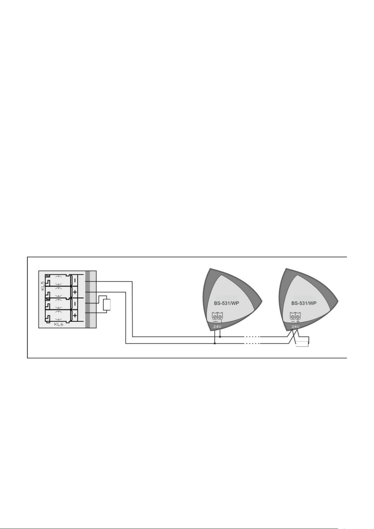
The panel contains 2 outputs that are used for connecting the sirens. These outputs are marked as
«AL1» and «AL2». Each output can provide up to 300mA and is monitored for open and short circuit
conditions. By default these terminals have an 8,2KΩ terminal resistor installed. If an output is not used
the then resistor must be left installed on the terminal. If the output is used then the terminal resist or is
removed and installed in parallel with the last siren.
By default both of these outputs are programmed to operate in case of an alarm condition.
On these outputs we can connected all the conventional sirens, bells or fire detection beacons (BS-530,
BS-531, BS-530/WP, BS-525).
The connections of both circuits are identical.
Figure 4-27. Connecting the sirens to the panel
Page 32
32 / 47
Date
30/9/2016
File
Document code
921163800_09_007
Page
32 from 47
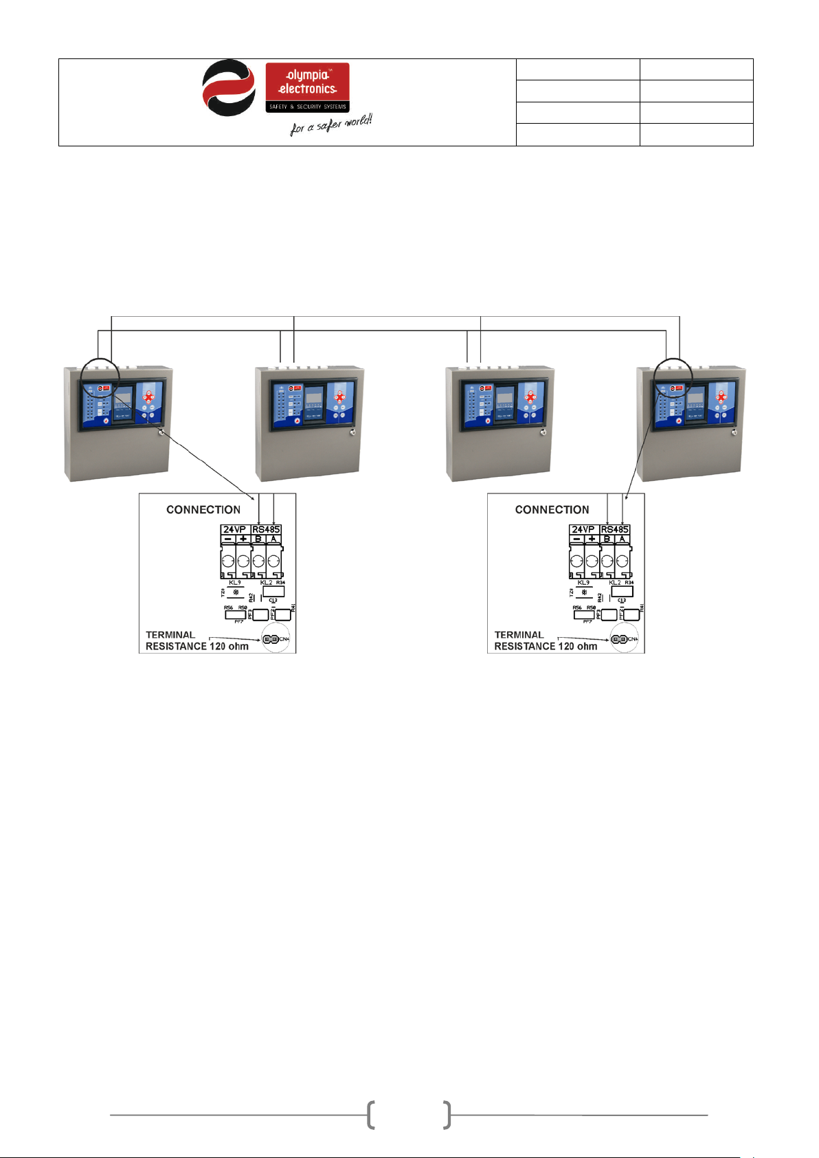
4.9 Connection to a network panels
It is possible to connect the panels to a network. Each panel in the network must have its own address.
The central panel has address 1 and the sub-panels from 2 to 16. The figure below shows the
connection between them.
The interface cable is bipolar twisted. The connection topology is parallel so the cable should be passed from one panel to another and there must not be any branches.
They can be connected up 16 panels on a network.
RS-485 is the communication protocol between the panels.
ATTENTION! Resistors 120Ohm/0. 5W should be placed at the beginning and the end of the cable. The
total cable length should not exceed 500m. For longer distances a RS-485 repeater should be used.
The cable shield must be connected to the grounding of the panel.
During the installation all sub-panels must first be addressed and then a search of the network must be
conducted from the central panel.
Page 33

33 / 47
Date
30/9/2016
File
Document code
921163800_09_007
Page
33 from 47
4.10 Other Connections
The following paragraphs mention all the connections that can be achieved with the panel.
Every connection must use a separate cable (e.i. a triple cable for connecting the panel to the
230VAC mains power supply, a double cable for the sirens e.t.c.).
The shield of each cable must be connected to the main ground terminals of the panel
The zone and input-output PCB contains the following outputs:
- 24V_M: A 24V dc output (up to 300mΑ) that is interrupted during a reset of the panel. It is used to
power gas detectors or other devices that need the power interrupted during a panel reset.
- 24V_P: A 24V dc output (up to 300mΑ) t hat is not interrupted during a panel reset. It can be
used to power electromagnetic door latches.
- Relay Alarm : Voltage free relays contacts that are activated during an alarm.
- Relay Fault : Voltage free relays contacts that are activated during a fault.
-
- Rel ay AUX : Voltage free relays contacts that are programmable from the panel.
WARNING: The maximum r ating of the relays is 30VDC and 3A.
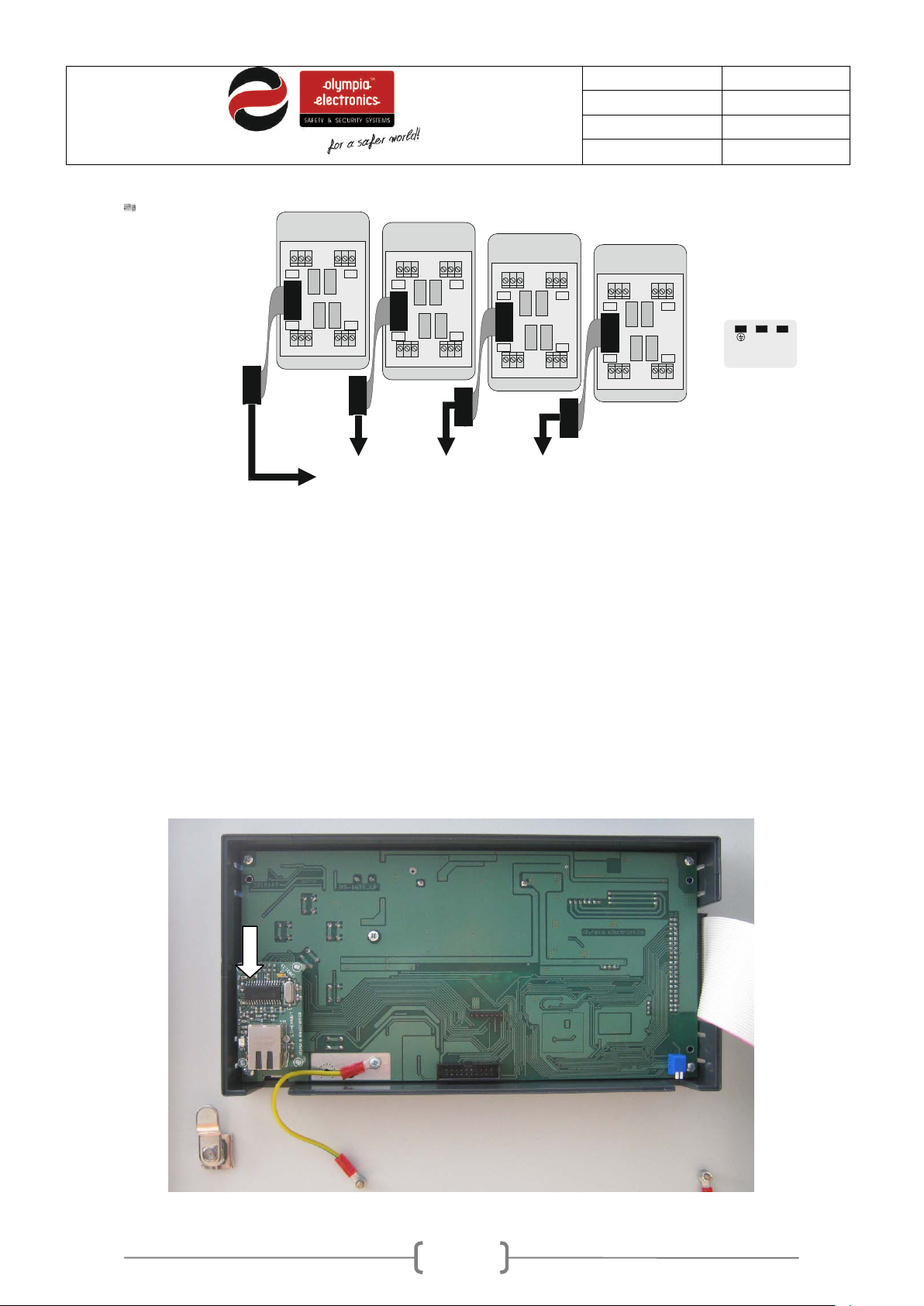
- Relay per Zone : The panel has outputs to connect up to 4 BS-613 ( 4 zone expansion card with
relays). For example, if we want the relay of zone 3 we must connect a BS-613 to the connector
Flat cable 1. The photo below shows which relay belongs to which zone.
Page 34
34 / 47
Date
30/9/2016
File
Document code
921163800_09_007
Page
34 from 47
BS-613
3 4
1 2
BS-613
7 8
5 6
BS-613
11 12
9 10
BS-613
15 16
13 14
2
2
0
-
2
4
0
V
A
C
L
N
Figure 4-28. Relay per BS-613 installation
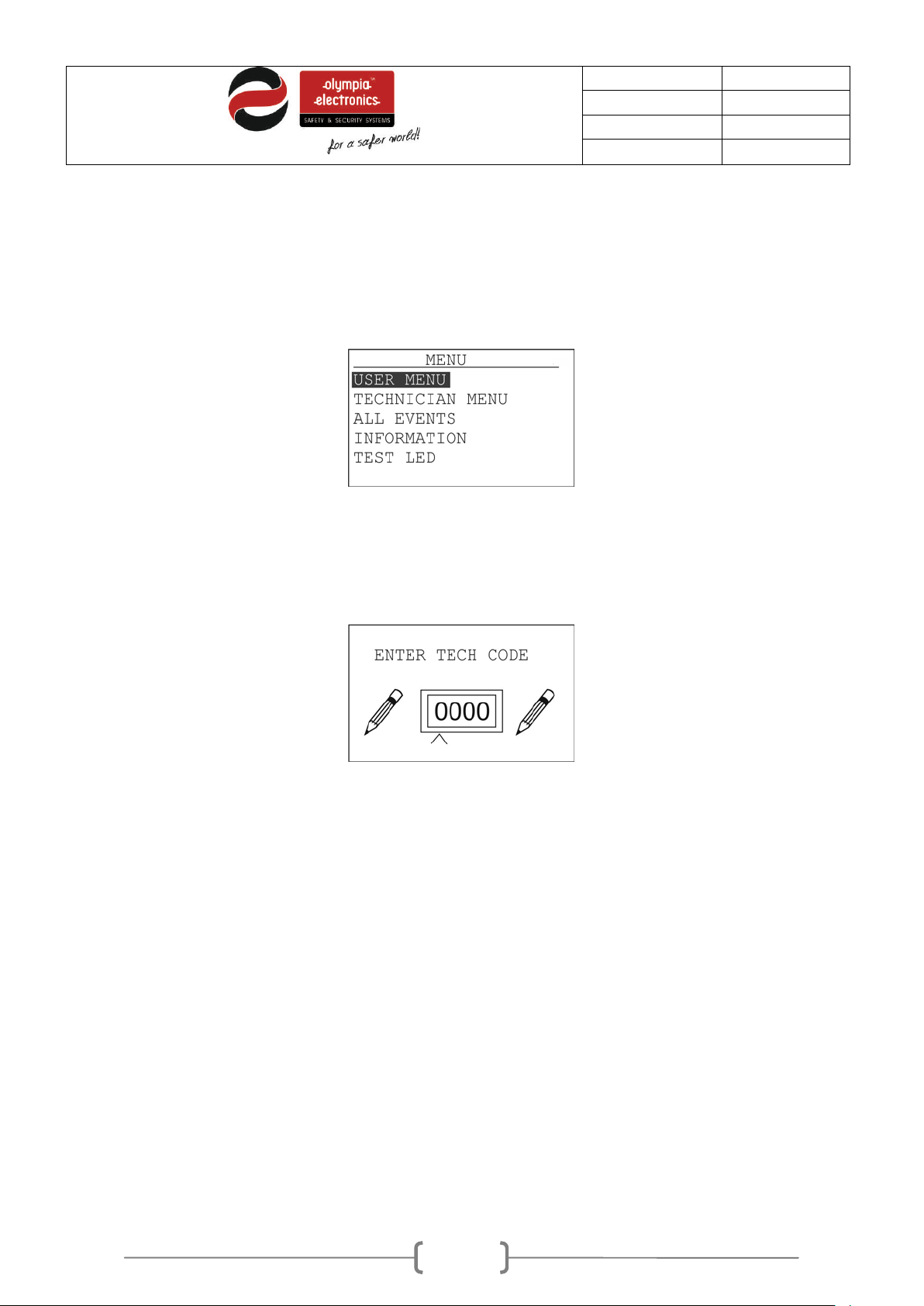
- Ethernet: To connect the panel to a local network use an ETHERNET cable type RJ45. The
ETHERNET card can be bought separately if it is not installed.
During the installation of the card the panel must not be operating and it must be installed
according to the photo below.
Page 35
35 / 47
Date
30/9/2016
File
Document code
921163800_09_007
Page
35 from 47
Figure 4-29. Installing an Ethernet card
5 Technician Menu
This section will cover all the options that are available in the Technicians Menu ( access level 3 and 4).
To enter the main menu of the panel press «ENTER» while in the initial screen.
Figure 5-30. Main Menu
Next select «TECHNICI AN MENU» and press «ENTER».
A code is required to enter access level 3.
Figure 5-31. Technician code
To select the code use the keys up, down, to increase the value of the digit and the keys rig ht-left to
change digits. After entering the complete code press Enter.
The factory default code is «2333».
Page 36
36 / 47
Date
30/9/2016
File
Document code
921163800_09_007
Page
36 from 47
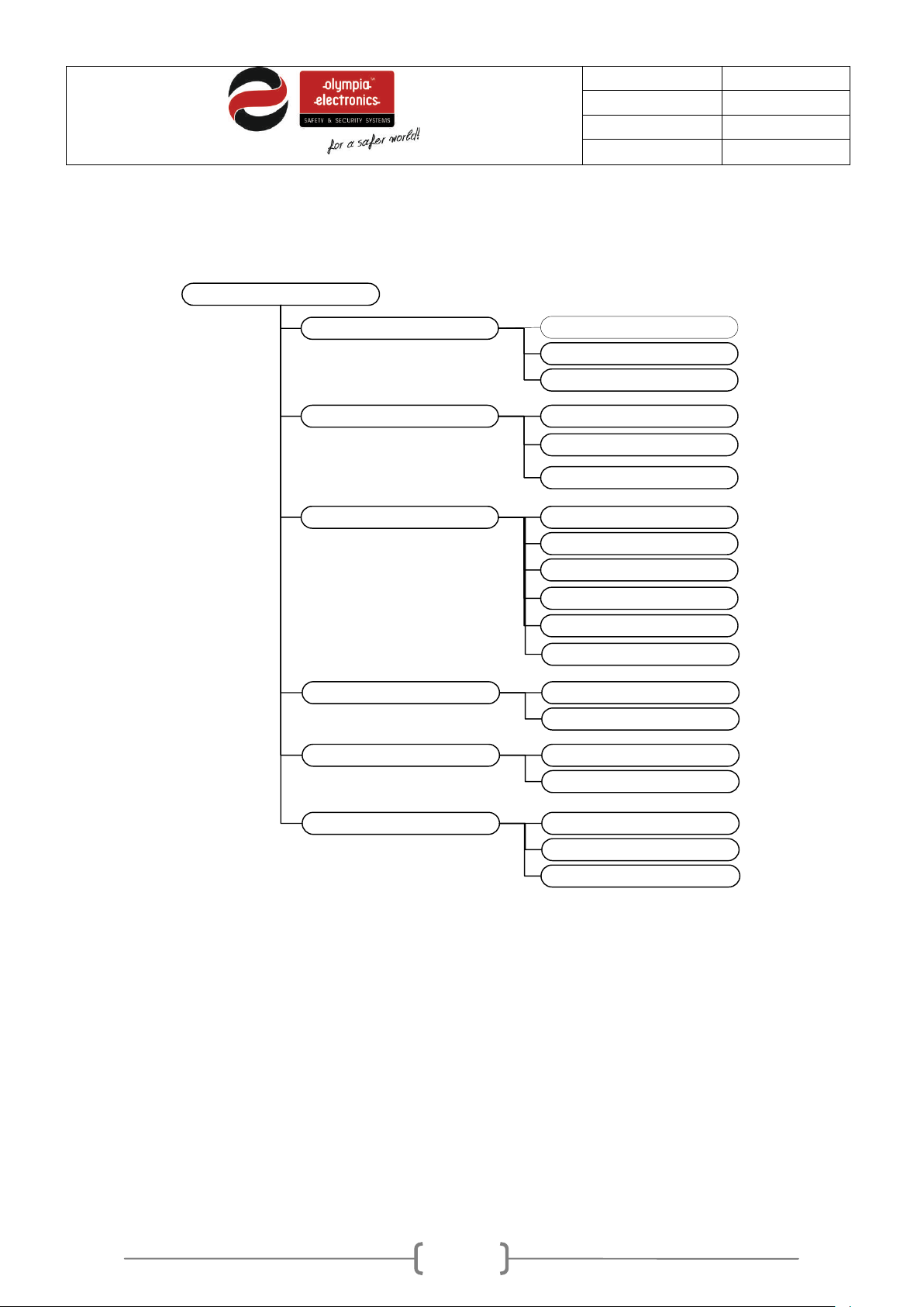
TECHNICIAN
TEST
CONFIGURATION
NETWORK
SETTINGS
NUMBER OF ZONES
SIRENS
AUXILIARY RELAYS
ETHERNET CARD
IP ADDRESS
RESET ETHERNET
SELECT LANGUAGE
ANNUAL TEST
FACTORY DEFAULTS
SET ZONES IN TEST
RESET ZONES IN TEST
ANNUAL TEST OK
ZONES IN TEST
CLEAR EVENTS NO
YES
RESET COUNTER NO
YES
MANUFACTURER MENU
CHANGE TECH CODE
Figure 5-3 shows the tree detail of this menu.
Figure 5-32. Technician menu
Next there will be a detailed description of each option.
5.1
Test menu
In this option we can adjust the state of each zone during the test. The setting is done using the option
«ZONES IN TEST» where we can select which zone will be on test.
After adjusting this we can test the zones without affecting the outputs of the panel. The state of the
zones in test can be found in the option INFORMATIONZONES ZONES IN TEST, ALARMS IN
TEST ZONES and FAULTS IN TEST ZONES.
To reset the zones to normal operation use the option «UNSET ZONE IN TEST».
Page 37
37 / 47
Date
30/9/2016
File
Document code
921163800_09_007
Page
37 from 47
m until the siren is
5.2
Setup menu
In this submenu basic elements of the panel are adjusted.
5.2.1 Number of zones
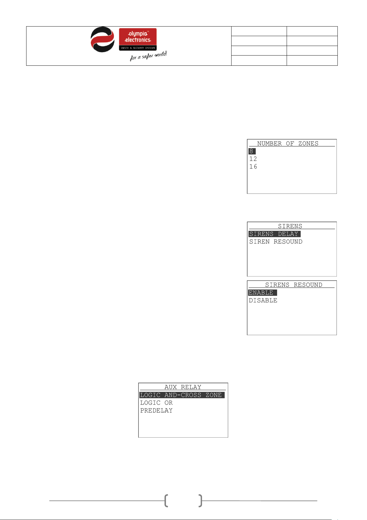
By selecting «NUMBER OF ZONES» we select the number of zones
that the panel has. There a 3 option as shown on t he adj ace nt scr een.
The BS-1638 panel has 8 zones, the BS-1642 panel has 12 zones
and the BS-1646 panel has 16 zones.
This option has to be changes only if a zone card is installed or
removed. BS-1640 (4 zones) or the BS-1641 (4 zones).
5.2.2 Sirens
This option has 2 submenus as shown in the adjacent screen.
We can adjust the delay of each siren from 0 to 6 minutes. This delay
starts from when the panel issues and alar
sounded. The delay is very useful in case of false alarms.
The second option determines the capability of automatically resounding the sirens when there is an alarm in a different zone. When
it is active then the sirens will sound when there is an alarm in a
different zone. In any other case they will not.
5.2.3 Aux Relay
The full function of the AUX relay is determined from t he following options. The options «LOGIC AND»
and «LOGIC OR» determine when the auxiliary relay will be activated.
Figure 5-33. Auxiliary relay configuration
Page 38
38 / 47
Date
30/9/2016
File
Document code
921163800_09_007
Page
38 from 47
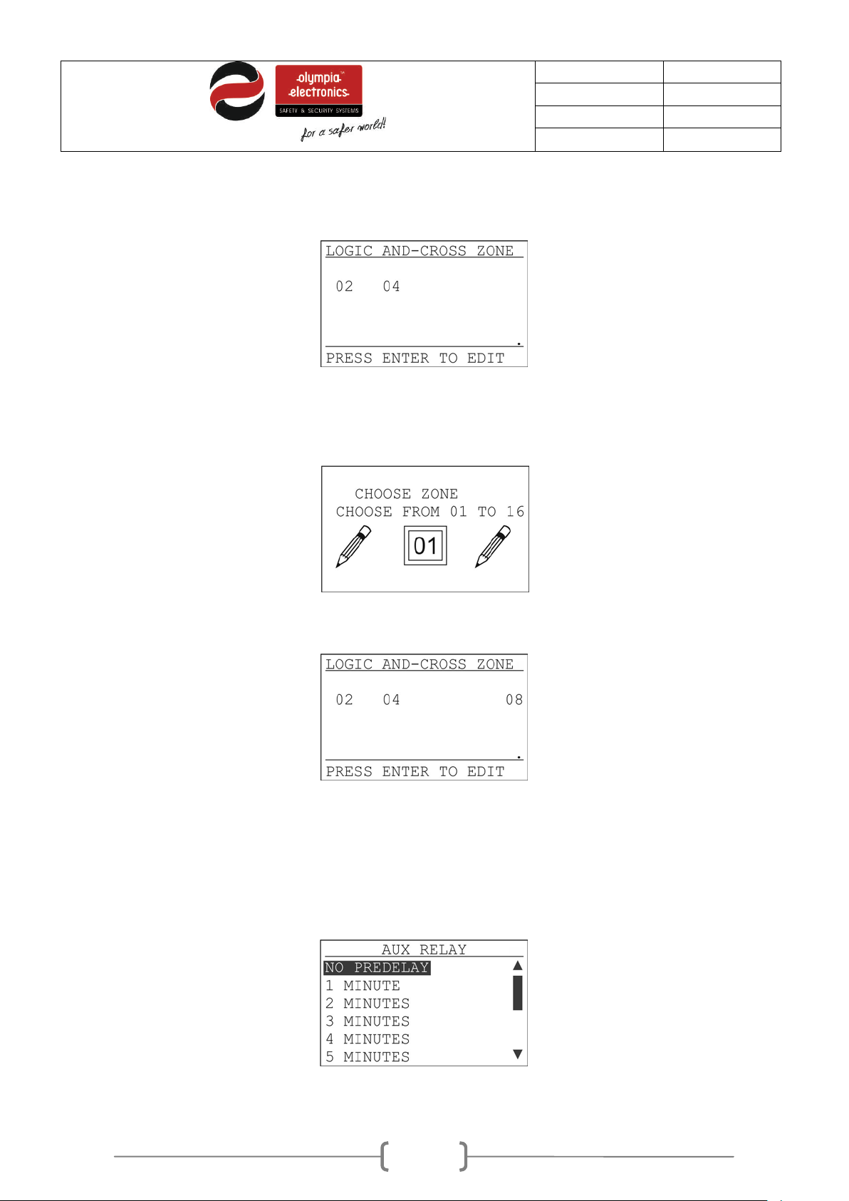
The option «LOGIC AND» (cross zone) determines which zones must be simultaneously activated in
order for the relay to be activated. For example, in one installation we want zones 2 and 4 cross-zoned.
Then we must have the following selected
Figure 5-34. Logic AND (cross zone)
This means that the both zones, 2 and 4 must issue an alarm for the auxiliary relay to be activated. If we
also want to cross-zones Zone 8 press «ENTER».
And with the keys «UP» and «DOWN» we select 08 and press «ENTER».
Now the cross-zones zones are 2,4 and 8. If we want to remove a zone we follow the same procedure.
With the key «ESC» we can exit from this option.
«LOGIC OR» (instant activation logic) determines which zones instantly activate the auxiliary relay
during an alarm.
The setting procedure is identical to the «LOGIC A ND» option.
Finally the delay of the auxiliary relay is set from 0 to 6 minutes.
Figure 5-35. Delay for the auxiliary relay
Page 39
39 / 47
Date
30/9/2016
File
Document code
921163800_09_007
Page
39 from 47
By selecting SELECT LANGUAGE and pressing ENTER we can see
5.2.4 Network configuration panel
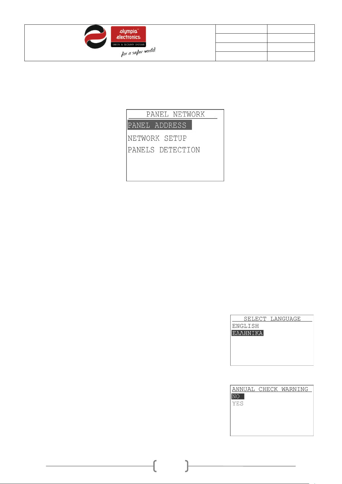
This option configures each panel in the network of panels.
Figure 5-36. Menu network panels
In option PANEL ADDRESS define the address of the panel in the network from 1 to 16. If it is 1 it is the
master panel. Otherwise it is a sub-panel.
In option NETWORK SETUP we declare if the network is enabled or disabled.
In the final option PANELS DETECTION detection is made by a central panel for all sub-panels
connected to it.
Settings Menu
5.3
5.3.1 Select Language
the adjacent screen. We can select the required language of the
system.
5.3.2 Annual check warning
This option activates or deactivates the annual maintenance warning
message.
Page 40
40 / 47
Date
30/9/2016
File
Document code
921163800_09_007
Page
40 from 47
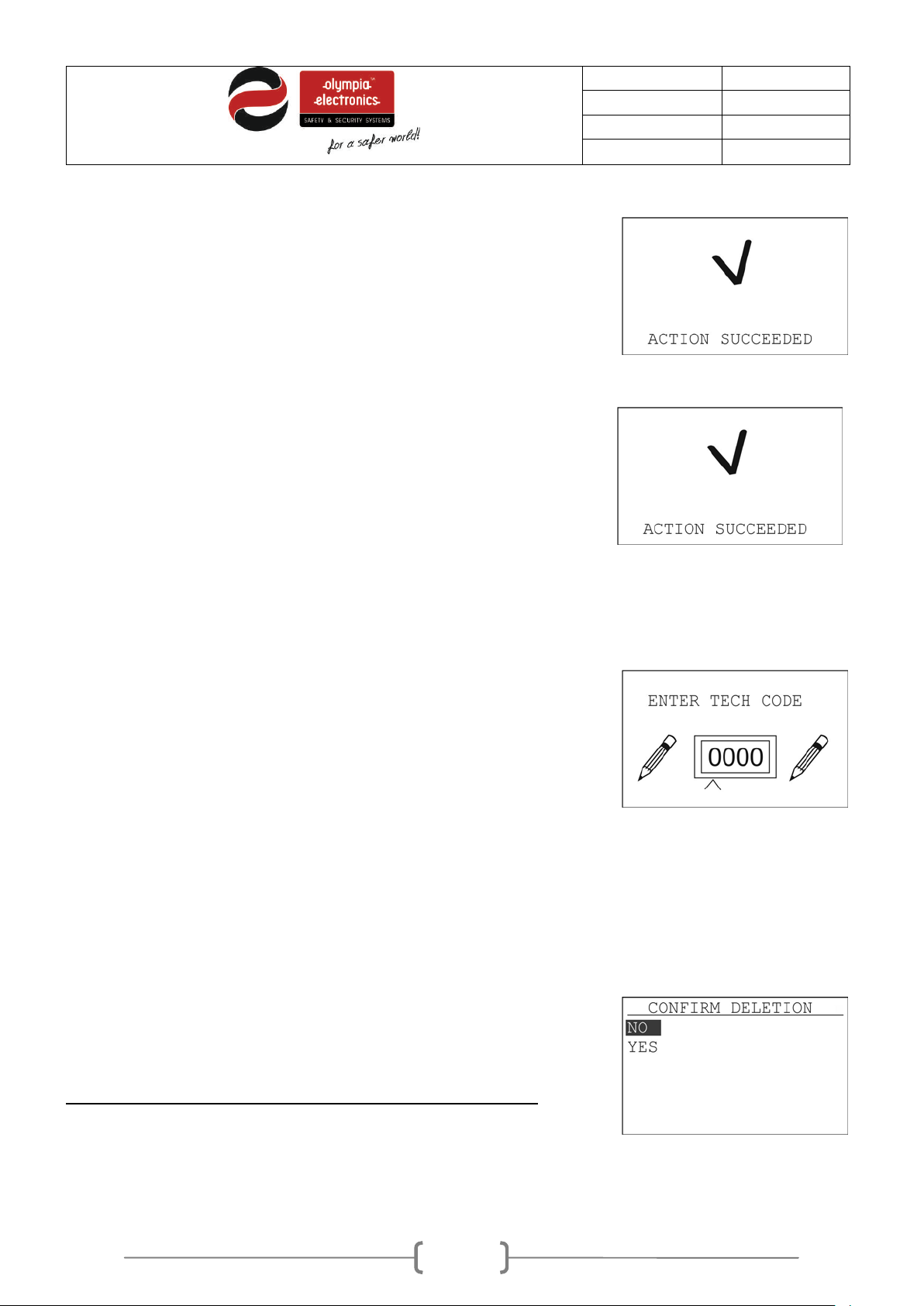
To initialize all settings to the factory defaults select RESET
. When you see the message in the
. Next the panel will
If we have a message for annual maintenance and we want to erase
When you see the message in the adjacent screen the
5.3.3 Reset defaults
DEFAULTS and press Enter
adjacent screen the operation has finished
initialize and start for the main screen.
5.3.4 Annual check done
the message select the option ANNUAL CHECK DONE and press
Enter.
operation has finished.
5.3.5 Changing the technician code
By selecting CHANG E TECH CODE we see th e adjacent screen. Use the
up-down keys to increas e or decrease the v alue of each digit and t he rightleft keys to change the digit . Once the new code has been e ntered pr ess the
ENTER key. The new code is also valid from programming with a P/C.
Finally there is the «MANUFACTURER MENU»
Clearing the events log
5.4
Selecting CLEAR EVENTS LOG and pressing Enter shows us the adjacent
screen. The panel requests confirmation. If we really want to clear the log
select YES and press Enter.
Erase the events log immediately after finalizing the installation.
Page 41
41 / 47
Date
30/9/2016
File
Document code
921163800_09_007
Page
41 from 47
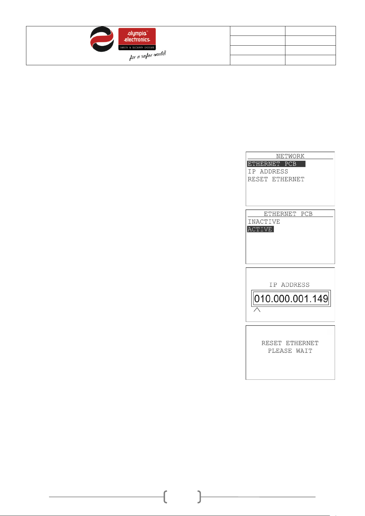
Selecting NETW ORK and press ing Enter shows us the opt ion for ne tworking
If we select IP ADDRESS and press Enter we see the adjacent screen . The
Resetting the alarm counter
5.5
This option gives us the capability to reset the alarms counter. The alarms counter is a counter that
counts all the alarm events and does not reset but only with this option. This opt ion is issued in access
level 4, that is why the DipSwitch 1 on the screen pcb must be in the ON position.
5.6
Network settings
the panel. The panel can be connec ted to the network in order to cooper ate
with other panels of to be programmed with a P/C. W e can see if the panel
has an Ethernet card i nstalled if we o pen the front li d. The Ethern et card will
be connected to the pc b located on th e lid of the panel. On this c ard we can
see the characteristic RJ-45 connector.
If there is an Ethernet card installed select the option ETHERNET PC B and
press Enter. In the next screen select ACTIVE and press Enter.
panel must have an addres s that is part of the networ k that it belo ngs to. As k
your network manager to p rovide this address for you. T he programming of
the address is done using the arrow keys. With the up-down keys we can
change the value of a digit and with the right-left keys we can change the
digits. When the required IP address has been entered press Enter. By
default the address is 10.0.1.149.
After any change in the network settings we must select the option RESET
ETHERNET. T his is to initialize the card with the new settings. T he screen
with show a message and it will return to the network menu.
5.7
Technician menu using the Ethernet
The programming of the panel can be done either by using the built-in keyboard and screen or
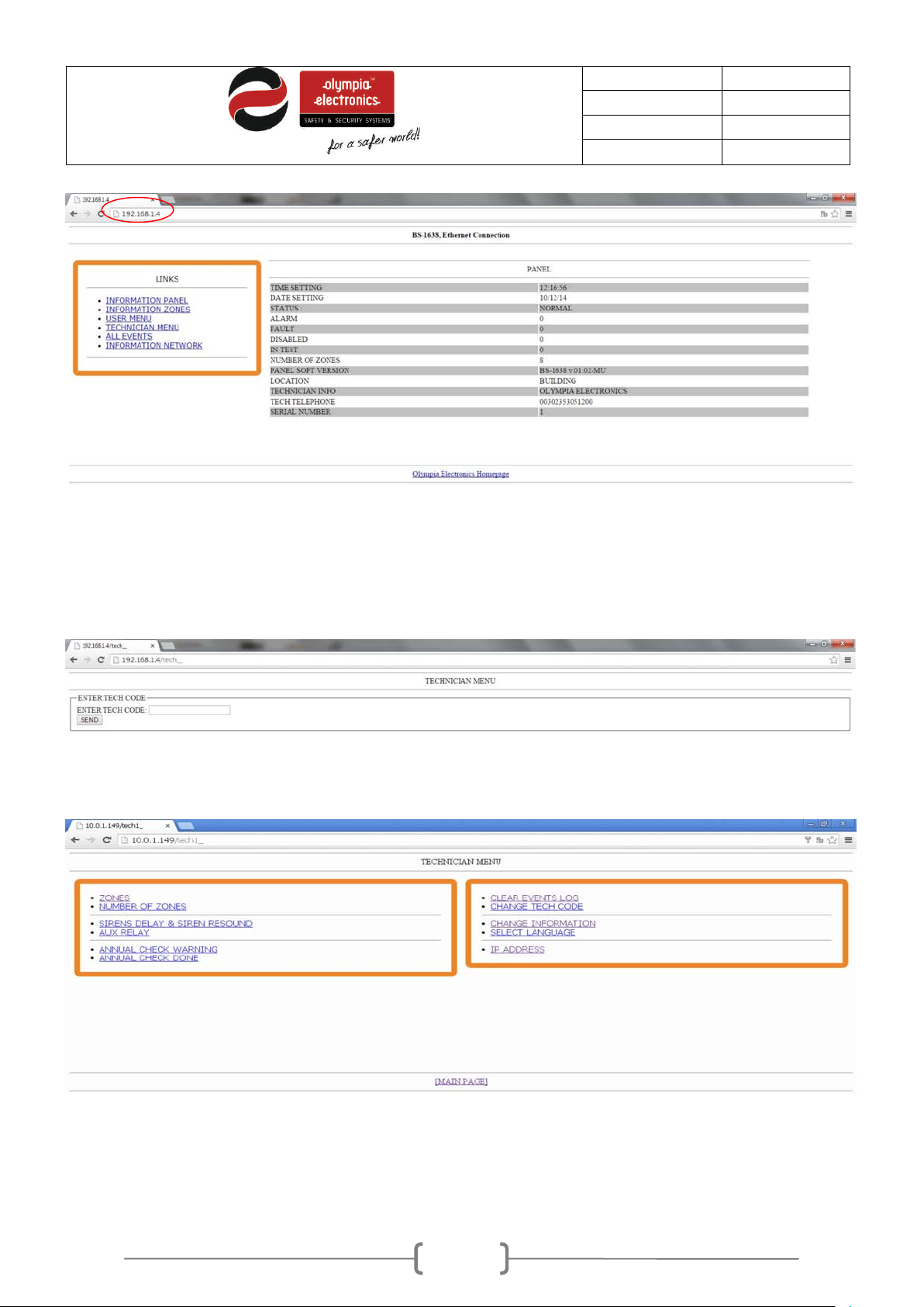
alternatively by using a P/C. The default IP address is 10.0.1.149. This can be changed to your
preference and according to your network as it has been done in the screen shots below.
Page 42
42 / 47
Date
30/9/2016
File
Document code
921163800_09_007
Page
42 from 47
Select the link TECHNICIAN MENU and the following screen is shown.
Place the cursor in the code entry field and type the correct technician code. After press SEND. If the
code is correct then we can see the TECHNICIAN MENU as below.
The structure of the menu is the same as in the technicians menu on the panel apart from some
difference that can only be programmed from the P/C and are not available in the corresponding
technician menu on the panel, such as changing the name of the zones.
Below are referenced in detail the options that are available only via the P/C.
Page 43
43 / 47
Date
30/9/2016
File
Document code
921163800_09_007
Page
43 from 47
5.7.1 Zone names
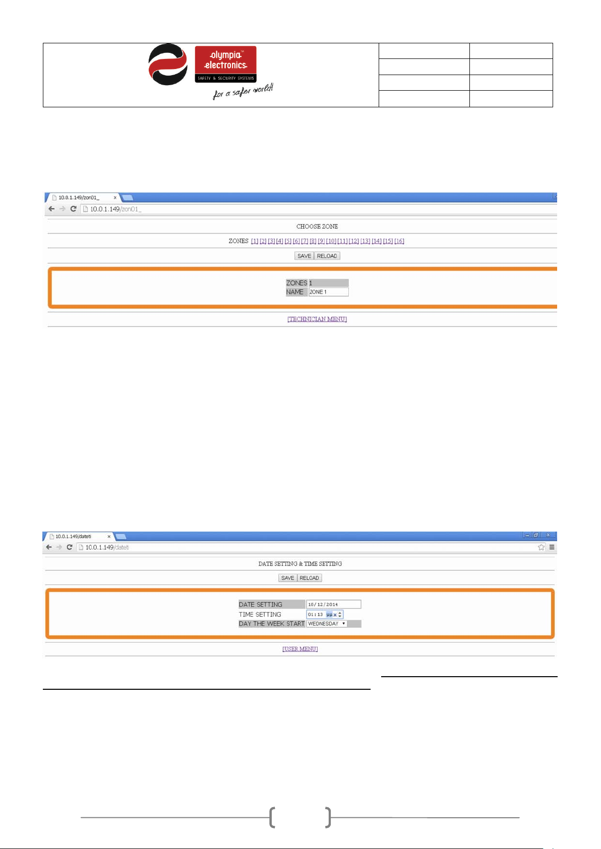
Using the mouse select ZONES and we can see the scr een below. T he operations that ar e selected are
the factory defaults for all the zones.
Via this selection we can program all options of the zones. First select the required zone and name it. Up
to 12 uppercase characters are permitted, once f inished press the SAVE button to store the changes.
Repeat the process for the other zones.
Select TECHNICIAN MENU to return to the initial screen of the technicians menu.
5.7.2 Setting the date and hour
Adjust the date, the time and the day of the week and press save.
the beginning of the installation for the logged events to be correct.
These settings must be adjusted in
By selecting TECHNICI AN MENU we return to the initial screen of the technician menu.
Page 44
44 / 47
Date
30/9/2016
File
Document code
921163800_09_007
Page
44 from 47
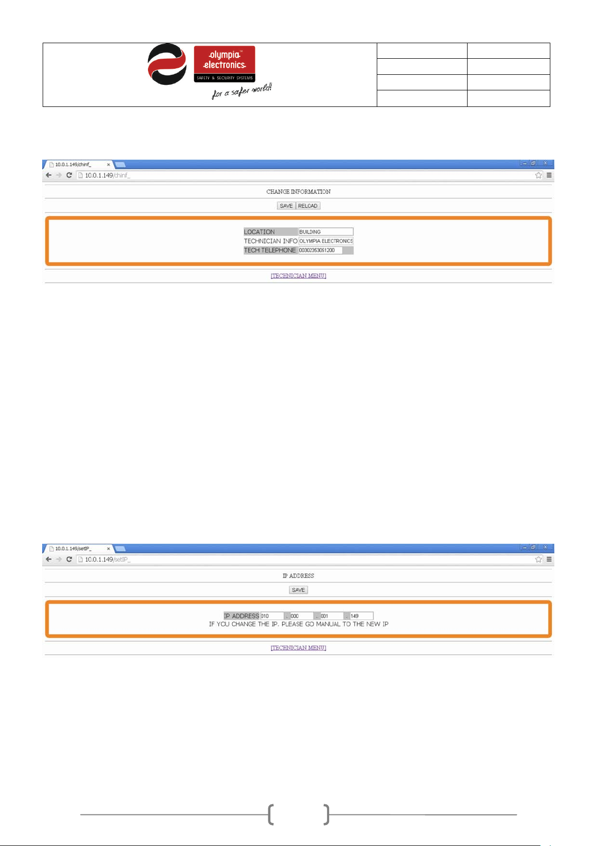
5.7.3 Other information
In this screen we can change the general information of the panel. The default information is shown in
the screen above. We can change the LOCATION (up to 24 characters), the TECHNICIAN
INFORMATION (up to 24 characters) and the TECHNICIAN TELEPHONE (up to 16 digits).
By pressing «SAVE» the changed settings are stored in the panel’s memory.
By selecting TECHNICI AN MENU we return to the initial screen of the technician menu.
5.7.4 ΙΡ address
In this screen we can change the IP address of the panel. The default subnet mask is [255.255.255.0].
After changing the IP address press «SAVE» to store the changes to the panel memory. After saving,
the communication with the panel will stop and we must manually enter the new IP address in the
browser to establish a new connection.
The number entered must be with 3 digits. For example, if we want to enter the IP 192.168.1.2 we must
enter it in the following manner 192.168.001.002.
Page 45
45 / 47
Date
30/9/2016
File
Document code
921163800_09_007
Page
45 from 47
Mains power supply
220-240V AC/50-60HZ
Battery type
2 sealed lead acid batteries 12V / 7Ah
Two 24V circuits that are monitored for open and short-circuit conditions
24VDC ( ±3VDC) permanent output with a maximum current of 0.3A.
The total output power (zone circuits, siren circuits,
Battery cut of voltage
21V
Battery maximum
Rimax
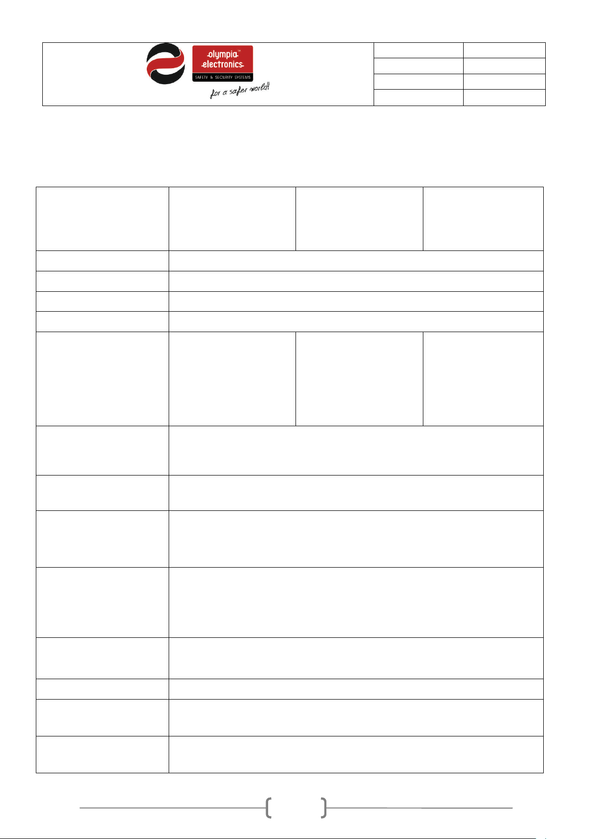
6 Technical Characteristics - Specifications
Description
BS-1638
Fire Detection panel
with 8 zones
BS-1642
Fire Detection panel
with 12 zones
Consumption 100 VA
Charger Stabilized power supply 27,6V / 350mA
12 circuits that
monitored for open and
short-circuit conditions
(maximum current
35mA)
Zone circuits
Alarm circuits
8 circuits that
monitored for open and
short-circuit conditions
(maximum current
35mA)
(The maximum current for each circuit is 300mA). Each output is protected
by a self resetting electronic fuse.
BS-1646
Fire Detection panel
with 16 zones
16 circuits that
monitored for open
and short-circuit
conditions (maximum
current 35mA)
Output 24P
Output 24M
Output relays
Total power
Maximum current
batteries discharge
internal resistance
μόνιμη έξοδος με μέγιστο ρεύμα εξόδου 0.3 A The output is protected by a
24VDC ( ±3VDC) output which is interrupted during a reset. The output
has a maximum current output of 0.3 A
The output is protected by a self resetting electronic fuse.
Three relay contacts that can handle up to 30V DC and 5A maximum.
Do not exceed these limits in any case.
All the output relays must be protected with fuses with the same rating.
outputs 24P and 24M) must not exceed 1A.
Imax a=Imax b=1A, Imin=60mA
1A
1Ohm
Page 46
46 / 47
Date
30/9/2016
File
Document code
921163800_09_007
Page
46 from 47
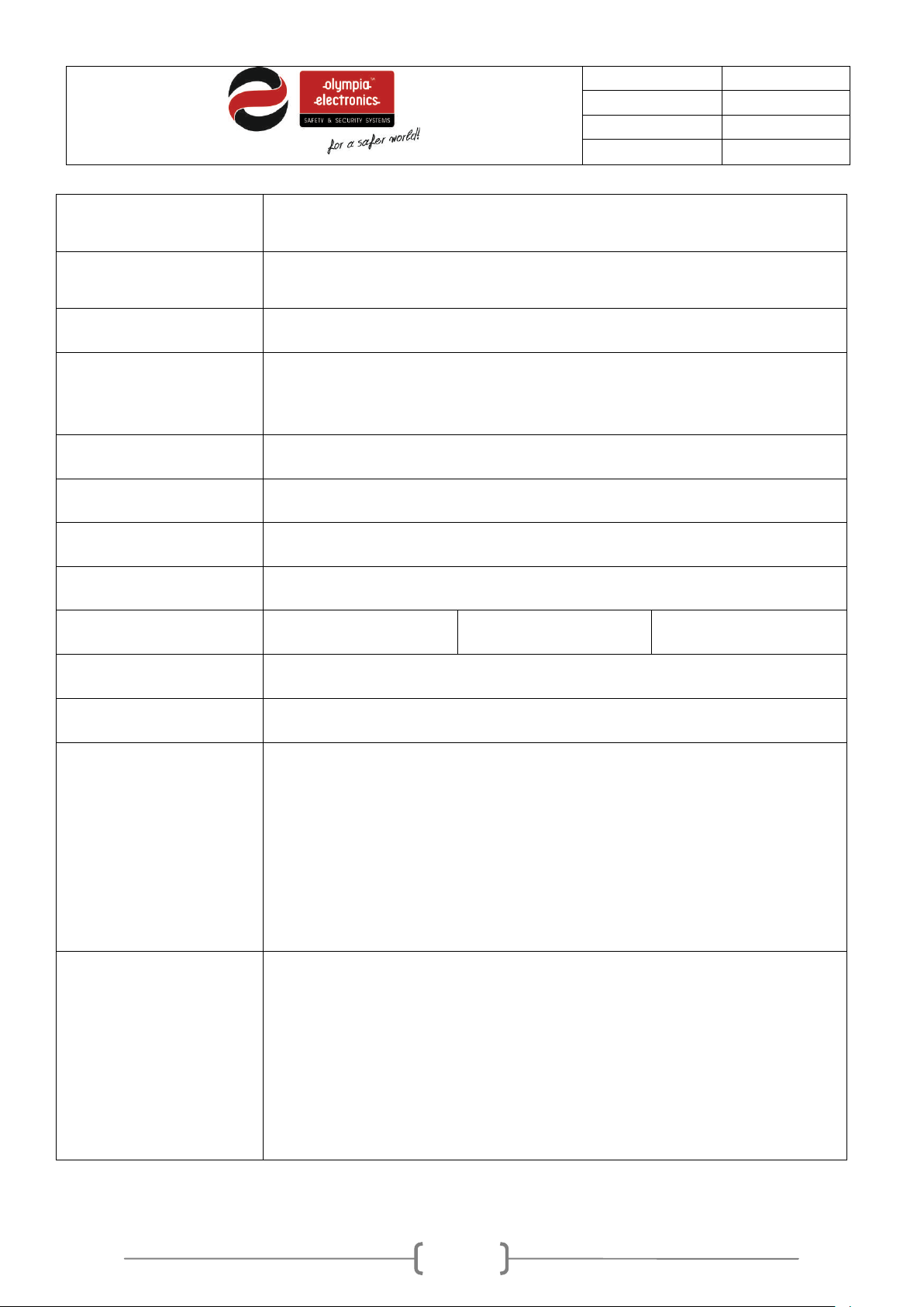
72 hours (Maximum number of connected detectors 220 and 16 zones, no
batteries.
Cables suitable for fire detection systems such as FIP200, MICC,
Operating temperature
Produced in accordance
Autonomy
Degrees of cover
protection
loads connected to the 24V M and 24VP outputs) with two 12V/7Ah
IP 30
Cables
PYROFIL
The panel has only one fuse that is replaceable and which protects the
Fuse type
main power supply connection. This fuse has a rating of F 4A 250V TR5
and must be replaced with a fuse of the same type and rating.
0 to 50 °C
range
Humidity Up to 95% relative humidity
Construction material ABS – polycarbonate, electrostatically painted steel
Dimensions (LxWxH) 345 x 106 x 348 mm
Weight(without batteries) 3740gr 3780gr 3820gr
with
Guarantee 2 years
Optional panel functions
Design
ΕΝ 54-2, ΕΝ 54-4
The optional functions of the panel according to the norm ΕΝ 54-2 are
• (Fire alarm device(s)) paragraph 7.8 ( ΕΝ 54-2 )
• (Test condition) paragraph 10 ( ΕΝ 54-2 )
• (Alarm counter) paragraph 7.13 ( ΕΝ 54-2 )
• (Delays to outputs) paragraph7.11 ( ΕΝ 54-2 )
Components of the panels have been selected for the intended purpose,
and are expected to operate within their specification when the
environmental conditions outside the cabinet of the panel comply with
class 3k5 of EN 60721-3-3:1995.
Page 47
47 / 47
Date
30/9/2016
File
Document code
921163800_09_007
Page
47 from 47
Certification
6.1
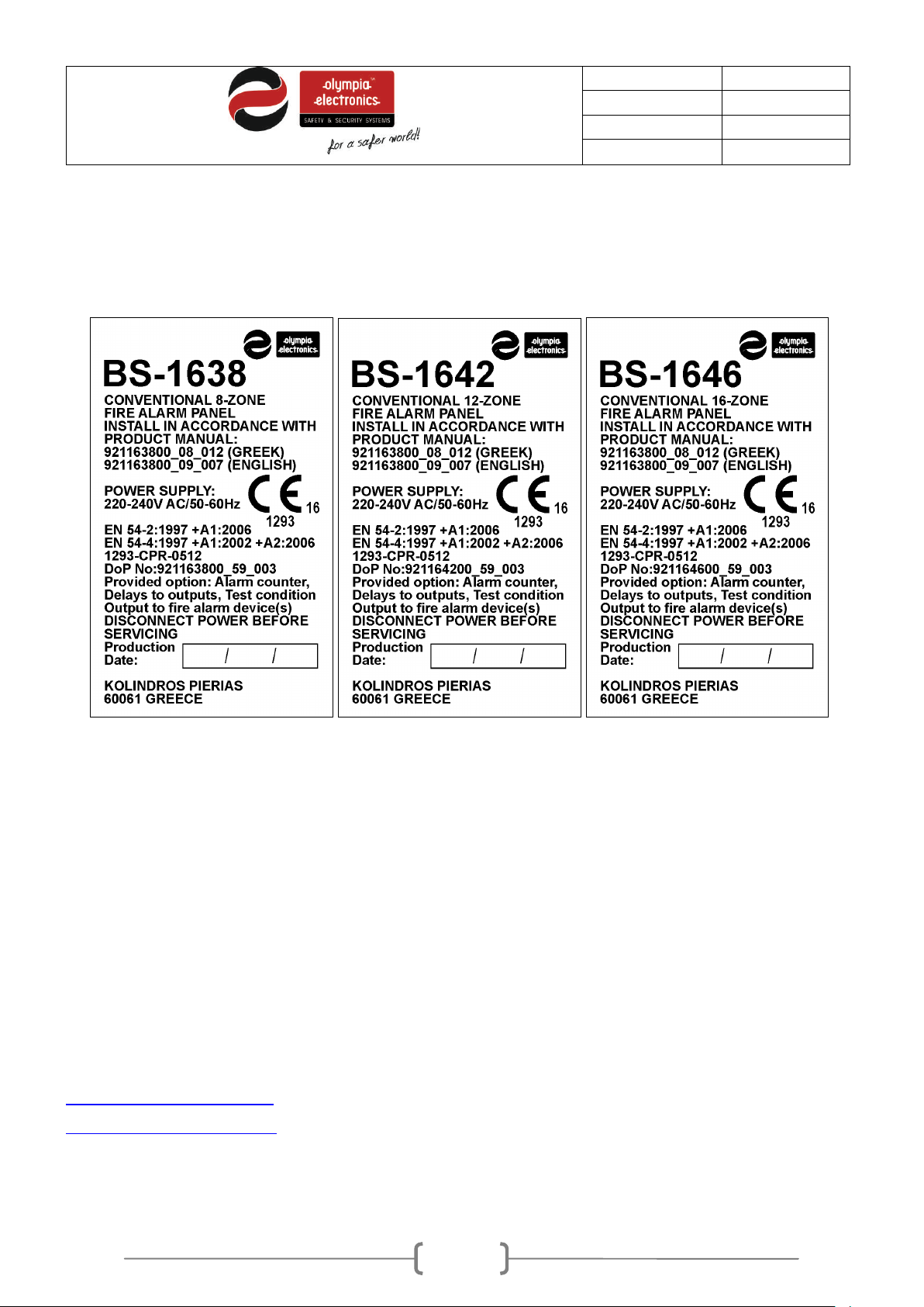
The panels BS-1638, BS-1642 and BS-1646 are certified from EVPU. Also EVPU controls the production
under CPR number: 1293-CPR-0512 for the panel BS-1638, BS-1642 and BS-1646. Below are the
markings:
WARRANTY
Olympia Electronics guarantees the quality, condition and operation of the goods. The period of warranty
is specified in the official catalogue of Olympia Electronics and also in the technical leaflet, which
accompanies each product. This warranty ceases to exist if the buyer does not follow the technical
instructions included in official documents given by Olympia Electronics or if the buyer modifies the
goods provided or has any repairs or re-setting done by a third party, unless Olympia Electronics has
fully agreed to them in writing. Products that have been damaged can be returned to the premises of our
company for repair or replacement, as long as the warranty period is valid.
Olympia Electronics reserves the right to repair or to replace the returned goods and to or not charge t he
buyer depending on the reason of defection. Olympia Electronics reserves the right to charge or not the
buyer the transportation cost.
HEAD OFFICE
72nd km. O.N.R. Thessaloniki-Katerini
P.C. 60061 Greece
 Loading...