

Page 1
ASSEMBLY INSTRUCTIONS FOR OSHW-GHOST KIT
OSHW-GHOST is small open source hardware board, created to teach novices soldering SMT
components. It’s easy to assembly and fun to use as it contain re-programmable PIC10F206
microcontroller which you can re-program yourself once you assembly the board.
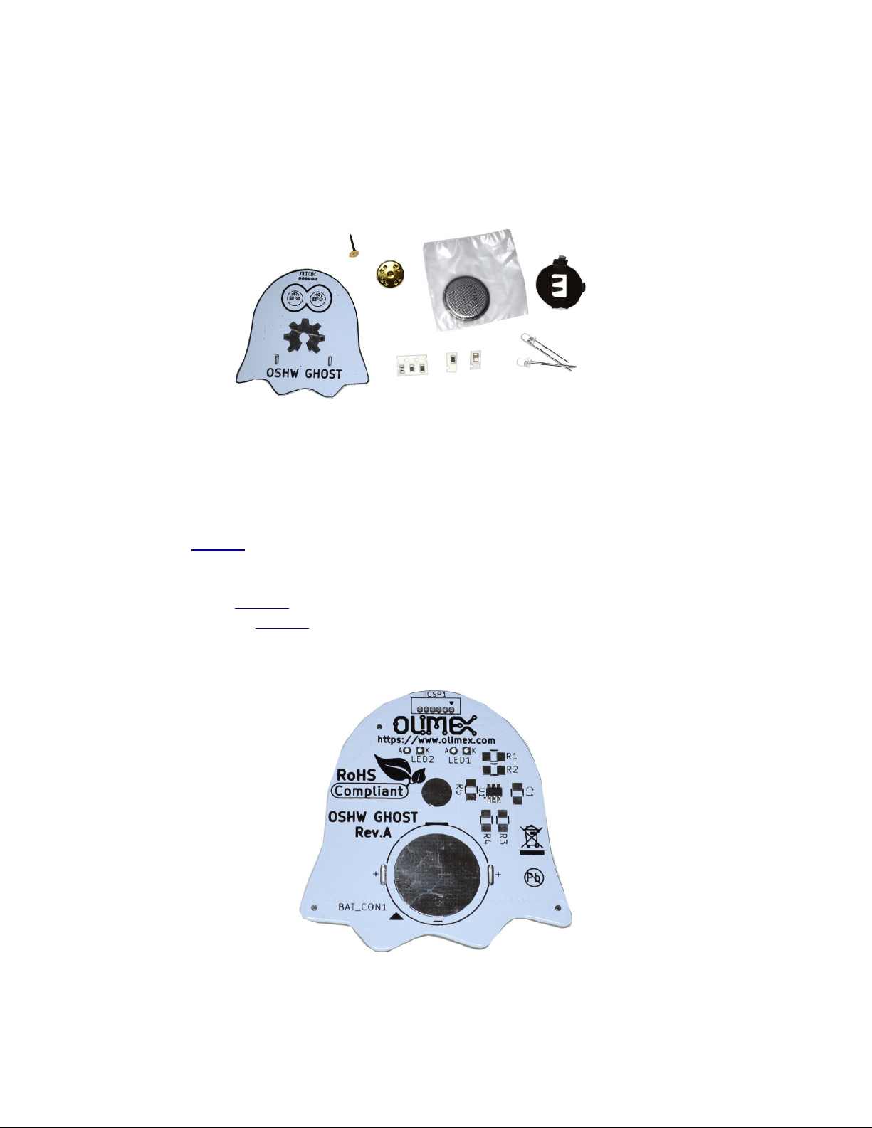
Here is how the kit looks like:
What you see is white printed circuit board, metal clip and pin which will allow you to attach this board
to your cloths, battery and metal battery holder, 3 resistors one capacitor and two high intensity green
LEDs with 3 mm diameter.
To solder this board you need:
- soldering iron, any with power 20-60W, thin tip and regulated temperature will do the job for
instance this one;
- solder with flux – we recommend to use 1 mm wire solder with 2.5% flux core;
- colophony (you can buy from any electronic store or music instruments store);
- tweezers like this one or similar;
- wire cutters like this one or similar;
Power up your soldering iron and set it to 300-350C temperature.
If you look at the PCB it comes with PIC microcontroller pre-soldered:
This is done intentionally for two reasons, first it’s hard to solder for novices, second to pre-program it
we use the ICSP1 connector on top, to program this PIC microcontroller in bulk requires special
adapter we do not have :)
Page 2
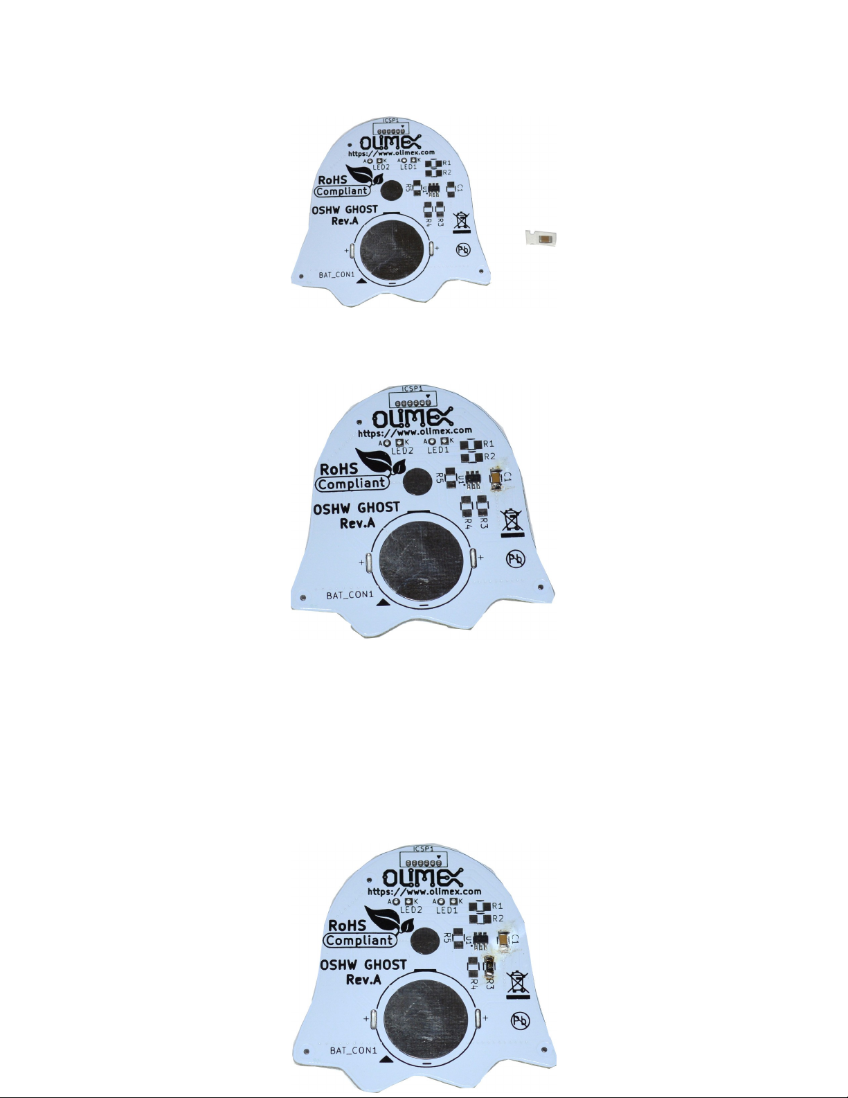
First you find the brown rectangle component in the paper tape. This is 100 nF capacitor:
You must peel the transparent tape and take off the capacitor then to solder it to C1 pads on the board
like on this picture.
The colophony flux in the solder wire do a little messy look but do not worry, at the end you can use
Isopropile or Ethyl alcohol with soft fabric to clean the flux residues. Even if not clean they are
harmless for the board, just will not look pretty as the picture above :)
Once the capacitor is soldered at it’s place find the single black component in paper tape, it has
marking 105. This is resistor with value 1 Mega Ohm. How this value 1Mega Ohm come from the 105
number? This three digit marking system for the resistor is composed by two digits and third which
says how many zeros to add after the two digit so 105 = 10 00000 or 1 000 000 ohms (1Mega means 1
Million ohms). This resistor must be soldered at R3 pads on the PCB:
Page 3
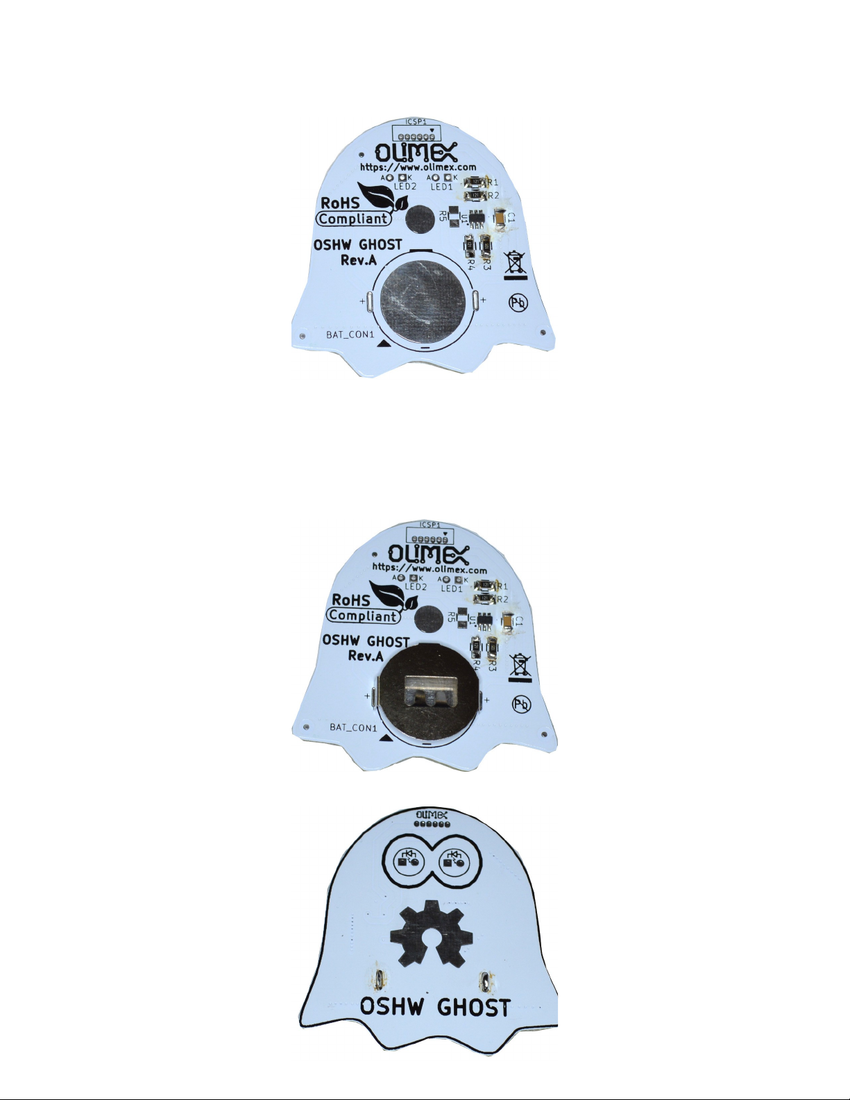
Then you need for find three resistors in paper tape, they are marked 121 = 120 or 120 Ohms! These
must be soldered to R1, R2, and R4 locations:
R5 and ICSP1 remains unpopulated, hey we soldered all SMT components, now to move to the
omponents with legs.
General rule of thumb when assembly boards is to assembly first the shorter components then the taller
ones as otherwise the tall components will make your assembly difficult.
We recommend now to solder first the battery holder, put it on th back side:
Then flip the PCB and solder the legs which are seen on front side:
Page 4
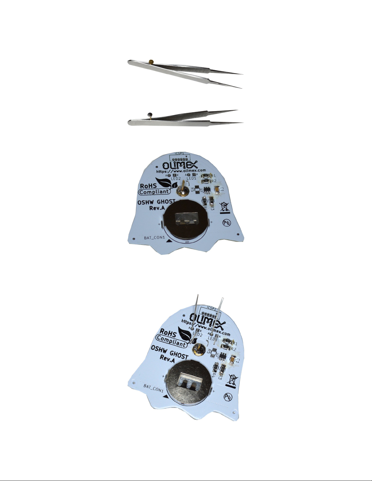
Again do not worry about the flux residues. To solder the brass pin to the PCB first you have to tin it’s
head, do not try to tin/solder it holding it with bare hand, use the tweezer for this purpose:
then touch the head of the pin with solder iron and add solder wire:
then using the tweezers hold the pin and solder it to the PCB:
We are almost done! Now put the LEDs on their places, but note that they have POLARITY so you
have to put them with the shorter leg inside the square pad (marked as K) and longer led in the circle
pad (marked as A).
Page 5
Then cut the legs with cutter and solder them:
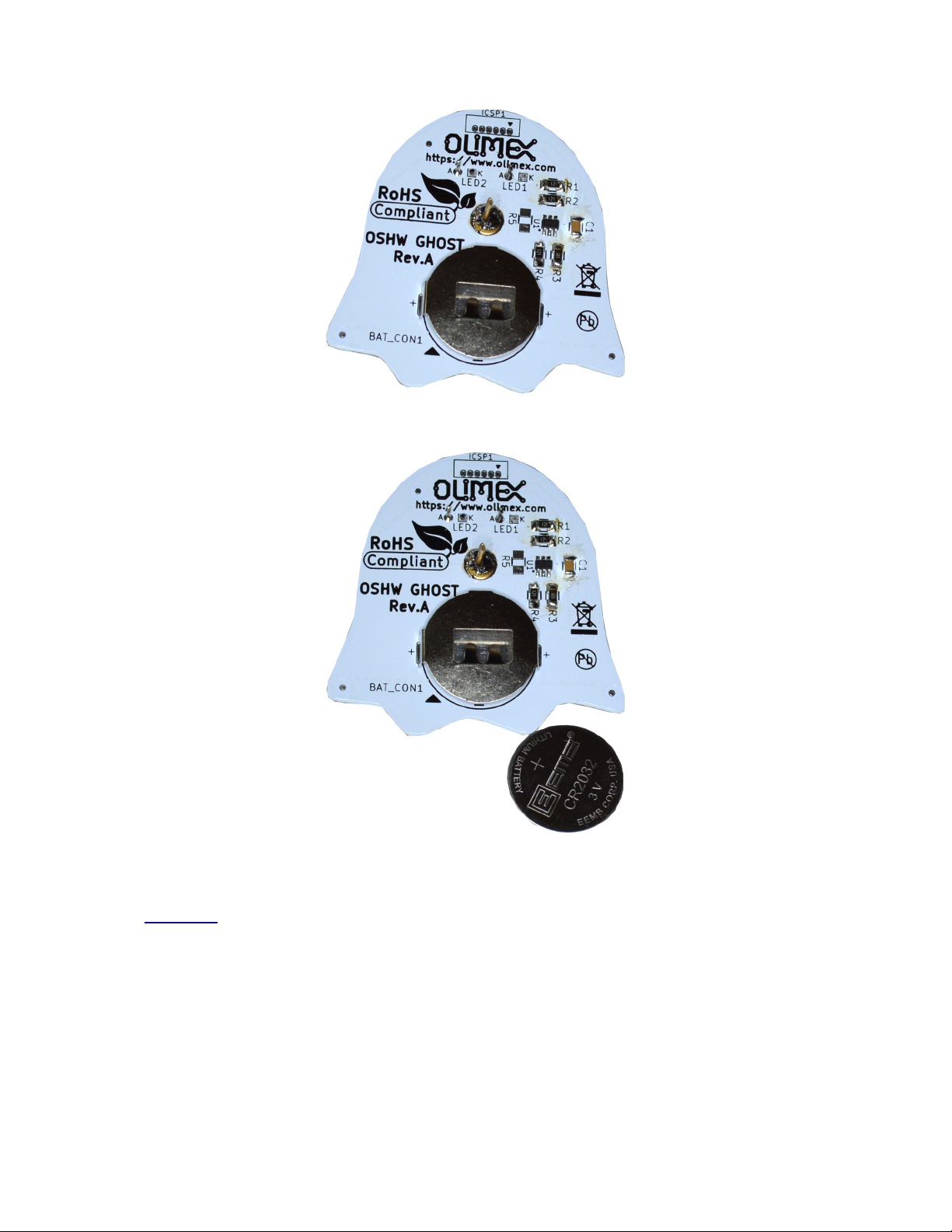
Now is time to attach the battery, again be careful as battery has polarity the + must be pointing UP as
on this picture:
All set, if you now touch and hold the OSHW logo for 1 second you will see the green LEDs blinking,
like on this video.
 Loading...