

Olicom CrossFire 8600, CrossFire 8605 Manual To Operations
DOC-6951/1.2
CrossFireTM 8600/8605
Token-Ring Switches
Guide to Operations


CrossFireTM 8600 /8605
Token- Ring S witches
Guide to Operations

ii
CLASS 1 LASER PRODUCT
Trademarks
GoCard and the Olicom cla s ped hands logo are register ed trademarks of Olicom A/S. CellD river,
ClearServer, ClearSession, ClearSight, CrossFire, LANscout, PowerMACH, RapidFire and RapidLAN
are trad emarks of Ol icom A/S. Cl ear Care, ClearPartner, ClearStep and ExpertWatch are service marks
of Olicom A /S. Olicom is a reg istered trademark. Other brand and pro duct names are trademarks,
register ed trademarks, service marks or registered se r vice marks of their respective holders.
Copyrights
Olicom A/S reserves the right to modify t he informa ti on given in this publication without pri or notice.
The war ranty te rms and c onditions applicabl e for y our purch as e of this equipment are gi ven at the time
of purchas e. Please cons ult your pl ace of purchase f or details.
Publi cation: DO C-6951 v. 1.2
Part Number: 710001641
© Copyright Olicom A/S,
All rights reserved
transmitted in any form or by any means, without the prior written permission of the publisher.
. No part of this publication may be re pr oduced, stored in a retr ieval syst em, or
Denmark, November 1998
FCC Compliance
This equipment has been tested and found to comply with the limits for a Class A digital device, pursuant
to Part 15 of the FC C Rul es. Thes e limi ts a re desi gned t o pro vide r easonab le protect ion ag ai nst har mful
interference when the equipment is operated in a commercial environment. This equipment generates,
uses and can radiate rad io frequency energy and, if not installed and used in accordance with the
instruct ion manual, ma y cause harmful interference to radio communication s . Operation of this
equipmen t i n a r es idential ar ea is likely to caus e har mf ul interfer ence in which case the user will be
required to correct the interference at his own expense.
Warning:
interfer ence in which case the user may be requi r ed to take adequ ate measures.
This device complies with part 15 of the FCC Rules. Operation is subject to the following two
condit ions: (1) This device may not cause harmful i nterference, and (2) this device must accept any
interfe r ence received, includi ng interference that may cause undesired operation.
This is a Class A product. In a domestic environment this product may cause radio
Declaration of Conformity
We Olicom A /S
Nybrovej 114
DK-280 0 Lyngby
Denmark
declar e under our sole re s ponsibility that the products
CrossFi re 8600 Token-Ring Switch and/or CrossFir e 8605 Toke n-Ring Fiber Switch
to which this declaration relates are in conformity with the following standards or other normative
documents
EN 50082-1
EN 55022
EN 60950 including Amendments
EN 60825-1
following the provisions of 89/336/EEC D irective and 73/23/E EC D ir ective.
CrossFire 8600/8605 Token-Ring Switches v. 1.2, P/N: 710001641

iii
Modifications
If the device i s changed o r modified without the express approval of Olico m A /S the user may void hi s
or her authority to operate the equipment.
Safety N otic e s
➽
➽
➽
➽
Danger:
maintenance, or reconfiguring of the CrossFire 8600 Token-Ring Switch and/or the CrossFire 8605
Token-Ring Fiber Switch during an electrical storm.
Danger:
the outlet before det aching the power cord from the CrossFire 8600 Token-Ri ng Switch and/ or the
CrossFire 8605 Token-Ring Fiber Switch.
Danger:
Fiber Sw itch. Dangerous vo lt ages inside .
Danger:
recept acle. Any equipment to which the Cross Fire 86 00 Token-Ring Switch and/or the Cros s Fire 8605
Token-Ring Fiber Switch will be attached must also be connected to properly wired and earthed
receptacles.
To avoid sho ck hazard, do not connect or dis connect any cables or perform install ation,
To avoid the possibility of electrical shock, switch power off and unplug the power cord from
Do not open the CrossFire 8600 Token-Ring Switch and/or the CrossFire 8605 Token-Ring
To avoid sho ck hazard the power cord must be connected to a properly wired and earthed
Caution:
Obser ve the following power cabl e considerat ions before you begin i ns tallation of the Cros s Fire 8600
Token- R ing Switch and/or the CrossFire 8605 Token-Ring Fiber Swi tch.
1. The socket outlet shal l be installed near the equipment and shall be eas ily access ible.
2. To prevent electrical shock, the power cord set used must comply with national regulations.
➽
➽
2a. The female receptacle of the cord must meet CEE-22 require ments.
2b. The cord must be UL liste d, CSA lab elle d , and cons ist of thre e condu cto rs with a maxi mum
of 15 fee t i n length.
Type SVT or SJ T cord sets shall be used fo r units which stand on a desk or table. Type SJT
cord sets shall be used for units wh ich stand on floor.
2c. The male plug for units operating at 115 V A C s hall consist of a parallel blad e, gr ounding
type attachment plug rated 15 A, 12 5 V A C.
The male plug for units op erating at 230 VAC shall consis t of a tandem blade, grounding
type attachment plug rated 15 A, 25 0 V A C.
The male plug for units op erating at 230 VAC (outside of the United States and Canada) s hall
consis t of a groundin g type attachment plug rated 15 A, 250 VAC and have the appropriate
safety approvals for the country in which the equi pment will be inst alled.
Caution:
Switch while you are installing the unit to avoid dropping it on the floor or any equipment beneath it in
the r ack. T he Cros sF ire 8600 T ok en-R ing S wi tch un i t and the C ross Fir e 86 05 T ok en-Ri ng Fiber Switc h
unit each w e ighs approximately 8.8 kg (19.4 lbs ) .
Warning:
loca l area ne t w o r king (L A N ) .
Suppor t the Cross Fire 8600 Token- Ring Switch and/or the CrossFire 8605 Token-Ri ng Fibe r
All RJ45 connectors must only be connected to safety extra low voltage (SELV) circuits like
CrossFire 8 600/8605 Toke n-Ring S witches v. 1.2, P/N: 710001 641

iv
CrossFire 8600/8605 Token-Ring Switches v. 1.2, P/N: 710001641

Table of Contents
1. Overview and Specifications 1
Switching Technology . . . . . . . . . . . . . . . . . . . . . . . 2
Switch of Switches . . . . . . . . . . . . . . . . . . . . . . . 2
Switch of Servers. . . . . . . . . . . . . . . . . . . . . . . . 3
Switch of Hubs . . . . . . . . . . . . . . . . . . . . . . . . . 3
Switch of Desktops. . . . . . . . . . . . . . . . . . . . . . . 3
Switch of Floors and Buildings . . . . . . . . . . . . . . . . . 4
Switch of Routers. . . . . . . . . . . . . . . . . . . . . . . . 4
Physical Characteristics . . . . . . . . . . . . . . . . . . . . . . 5
Out-of-Band Management (OBM) . . . . . . . . . . . . . . . 5
Token-Ring Ports. . . . . . . . . . . . . . . . . . . . . . . . 6
Switched Port Analyzer. . . . . . . . . . . . . . . . . . . . . 6
Universal Expansion Slots and Modules . . . . . . . . . . . . 7
Reset Button . . . . . . . . . . . . . . . . . . . . . . . . . . 7
System Request Button . . . . . . . . . . . . . . . . . . . . 7
Labels . . . . . . . . . . . . . . . . . . . . . . . . . . . . . 7
Status and Activity LEDs . . . . . . . . . . . . . . . . . . . . 8
Features and Specifications . . . . . . . . . . . . . . . . . . . 10
Features . . . . . . . . . . . . . . . . . . . . . . . . . . . 10
Specifications. . . . . . . . . . . . . . . . . . . . . . . . . 1 2
v
2. Switch Theory of Operation 17
How the CrossFire 8600 and the CrossFire 8605 Works . . . . 17
Multiple Simultaneous Conversati ons . . . . . . . . . . . . 18
Low Latency . . . . . . . . . . . . . . . . . . . . . . . . . 19
Address Management . . . . . . . . . . . . . . . . . . . . 19
Multiple Bridging Modes . . . . . . . . . . . . . . . . . . . 20
Filtering. . . . . . . . . . . . . . . . . . . . . . . . . . . . 22
Congestion Control. . . . . . . . . . . . . . . . . . . . . . 2 3
Three Switching Modes . . . . . . . . . . . . . . . . . . . 23
Token-Ring Port Operation Modes. . . . . . . . . . . . . . 24
RI/RO-Like Connection. . . . . . . . . . . . . . . . . . . . 24
Transmission Priority Queues . . . . . . . . . . . . . . . . 25
CrossLink Connections. . . . . . . . . . . . . . . . . . . . 25
Spanning Tree Protocol Support . . . . . . . . . . . . . . . 2 5
VLAN Support . . . . . . . . . . . . . . . . . . . . . . . . 26
Management . . . . . . . . . . . . . . . . . . . . . . . . . 27
RMON Support. . . . . . . . . . . . . . . . . . . . . . . . 28
Built-in Port Counters. . . . . . . . . . . . . . . . . . . . . 2 9
Stackable Architecture . . . . . . . . . . . . . . . . . . . . 30
CrossFire 8 600/8605 Toke n-Ring S witches v. 1.2, P/N: 710001 641

vi
Optional Redundant Power Supply . . . . . . . . . . . . . .30
Benefits of the CrossFire 8600 and the CrossFire 8605. . . . . .32
3. Preparing for Installation 43
Safety Recommendations . . . . . . . . . . . . . . . . . . . . .43
Safety with Electricity . . . . . . . . . . . . . . . . . . . . .43
Preventing Electrostatic Discharge Damage . . . . . . . . .45
Site Requirements. . . . . . . . . . . . . . . . . . . . . . . . .46
Environment . . . . . . . . . . . . . . . . . . . . . . . . . .46
Chassis Accessibility . . . . . . . . . . . . . . . . . . . . .46
Cooling and Airflow . . . . . . . . . . . . . . . . . . . . . .46
Power . . . . . . . . . . . . . . . . . . . . . . . . . . . . .46
Unpacking and Inspecting . . . . . . . . . . . . . . . . . . . . .48
Rules to Remember . . . . . . . . . . . . . . . . . . . . . . . .49
Frame Length Limit . . . . . . . . . . . . . . . . . . . . . .49
Cables and Distances between Devices . . . . . . . . . . .49
Sample Applications for the CrossFire 8600 and
the CrossFire 8605 . . . . . . . . . . . . . . . . . . . . . . . .50
Important Managem ent Considerati ons . . . . . . . . . . . .54
4. Installation 55
Required Network Preparation - Frame Length Limit . . . . . . .55
Installation Summary . . . . . . . . . . . . . . . . . . . . . . .56
Unpacking Instructions. . . . . . . . . . . . . . . . . . . . . . .57
Materials Needed for Installation . . . . . . . . . . . . . . . . .57
Installing a Universal Expansion Module . . . . . . . . . . . . .58
Mounting the Chassis . . . . . . . . . . . . . . . . . . . . . . .59
Rack or Cabinet Mounting. . . . . . . . . . . . . . . . . . .59
Table-Mounting . . . . . . . . . . . . . . . . . . . . . . . .60
Cabling. . . . . . . . . . . . . . . . . . . . . . . . . . . . . . .61
Connecting Devices to the Token-Ring Ports . . . . . . . . .61
Connecting Devices to the Token-Ring Ports
Using Building Wiring . . . . . . . . . . . . . . . . . . . . .62
Checking the Installation . . . . . . . . . . . . . . . . . . . . . .63
Applying Power . . . . . . . . . . . . . . . . . . . . . . . . . .64
Control Panels . . . . . . . . . . . . . . . . . . . . . . . . . . .66
Front Panel . . . . . . . . . . . . . . . . . . . . . . . . . .66
Back Panel. . . . . . . . . . . . . . . . . . . . . . . . . . .68
5. Connecting a Network Management Console 69
Connecting the Console . . . . . . . . . . . . . . . . . . . . . .69
Communication Problems . . . . . . . . . . . . . . . . . . .71
Diagnostic Screen . . . . . . . . . . . . . . . . . . . . . . .72
CrossFire 8600/8605 Token-Ring Switches v. 1.2, P/N: 710001641

vii
6. Switch Configuration 75
General Guidelines. . . . . . . . . . . . . . . . . . . . . . . . 76
Navigating within the Menus . . . . . . . . . . . . . . . . . 7 7
Main Menu . . . . . . . . . . . . . . . . . . . . . . . . . . . . 78
Configuration... . . . . . . . . . . . . . . . . . . . . . . . . 78
Statistics... . . . . . . . . . . . . . . . . . . . . . . . . . . 78
Download/Upload... . . . . . . . . . . . . . . . . . . . . . 7 8
Reset.... . . . . . . . . . . . . . . . . . . . . . . . . . . . 78
Exit Console . . . . . . . . . . . . . . . . . . . . . . . . . 78
Configuration Menu . . . . . . . . . . . . . . . . . . . . . . . 79
Switch Configuration Screen . . . . . . . . . . . . . . . . . . . 81
Stack Configuration Screen . . . . . . . . . . . . . . . . . 8 4
Module Information Screen. . . . . . . . . . . . . . . . . . 85
VLAN Configuration . . . . . . . . . . . . . . . . . . . . . . . 87
VLAN Configuration Menu . . . . . . . . . . . . . . . . . . 88
VLAN Configuration Screen . . . . . . . . . . . . . . . . . 89
VLAN Para meter C o n figurati o n for T r C RF Scr e en. . . . . . 90
VLAN Parameter Conf ig u r a tion for Tr BRF Sc r e e n . . . . . . 92
Local VLAN Port Configuration Screen . . . . . . . . . . . 93
IP Configuration Screen . . . . . . . . . . . . . . . . . . . . . 94
BootP Requests and Parameters . . . . . . . . . . . . . . 96
SNMP Configuration Menu. . . . . . . . . . . . . . . . . . . . 97
Spanning Tree Protocol . . . . . . . . . . . . . . . . . . . . . 97
IEEE 802.1D Spanning Tree Protocol (STP). . . . . . . . . 98
Spanning Tree for TrBRF Screen . . . . . . . . . . . . . . 99
Spanning Tree for TrCRF Screen . . . . . . . . . . . . . .101
Port Spanning Tree Parameters Screen . . . . . . . . . . .103
Current Spanning Tree Information Screen . . . . . . . . .104
Port Configuration Screen . . . . . . . . . . . . . . . . . . . .105
Switched Port Analyzer Menu . . . . . . . . . . . . . . . . . .109
CrossLink. . . . . . . . . . . . . . . . . . . . . . . . . . . . .109
CrossLink Menu . . . . . . . . . . . . . . . . . . . . . . .111
CrossLink Configuration Screen . . . . . . . . . . . . . . . 112
Setting up a CrossLink . . . . . . . . . . . . . . . . . . . .113
Current CrossLink Information Screen . . . . . . . . . . . .114
Address Filtering . . . . . . . . . . . . . . . . . . . . . . . . .115
Filters and Port Security Menu . . . . . . . . . . . . . . . . 116
Configure Filters Screen . . . . . . . . . . . . . . . . . . . 117
Configure Port Security Mode Screen . . . . . . . . . . . .119
View Port Filters Screen . . . . . . . . . . . . . . . . . . . 120
Protocol Filters Menu. . . . . . . . . . . . . . . . . . . . .121
Protocol Class Assignment Screen . . . . . . . . . . . . .122
Port Filtering Attributes Screen . . . . . . . . . . . . . . . . 123
CrossFire 8 600/8605 Toke n-Ring S witches v. 1.2, P/N: 710001 641

viii
Address Aging . . . . . . . . . . . . . . . . . . . . . . . . . . 125
Address Aging Menu . . . . . . . . . . . . . . . . . . . . 126
Port Address Table Aging Screen. . . . . . . . . . . . . . 127
Master Address Table Aging Screen . . . . . . . . . . . . 128
Password Menu . . . . . . . . . . . . . . . . . . . . . . . . . 129
Console/Telnet Sessions . . . . . . . . . . . . . . . . . . . . 130
Console Configuration Menu . . . . . . . . . . . . . . . . 130
Serial Link Configuration Screen . . . . . . . . . . . . . . 131
Creating a Console Session Using a Modem . . . . . . . . 132
Stopping the Console Session. . . . . . . . . . . . . . . . 132
Telnet Configuration Screen. . . . . . . . . . . . . . . . . 133
Telnet Sessions Screen . . . . . . . . . . . . . . . . . . . 134
Starting the Telnet Session . . . . . . . . . . . . . . . . . 135
Stopping the Telnet Session . . . . . . . . . . . . . . . . . 135
Involuntary Termination of the Telnet Session . . . . . . . 135
Download/Upload Menu . . . . . . . . . . . . . . . . . . . . . 137
Serial Link Download Screen . . . . . . . . . . . . . . . . 138
TFTP. . . . . . . . . . . . . . . . . . . . . . . . . . . . . 139
TFTP Download/Upload Screen. . . . . . . . . . . . . . . 139
Reset Screen . . . . . . . . . . . . . . . . . . . . . . . . . . 142
7. Monitoring th e Network with th e Console 145
Navigating Within the Menus . . . . . . . . . . . . . . . . . . 146
Statistics Menu. . . . . . . . . . . . . . . . . . . . . . . . . . 147
Switch Statistics Screen . . . . . . . . . . . . . . . . . . . 148
Port Status Screen. . . . . . . . . . . . . . . . . . . . . . 150
Port Statistics Menu . . . . . . . . . . . . . . . . . . . . . 152
General Statistics Screen . . . . . . . . . . . . . . . . . . 153
802.5 Statistics Screen . . . . . . . . . . . . . . . . . . . 156
802.5 State Information Screen . . . . . . . . . . . . . . . 159
802.5 DTR MAC Information Menu . . . . . . . . . . . . . 160
TXI Information Screen . . . . . . . . . . . . . . . . . . . 161
Station-CPort Information Screen . . . . . . . . . . . . . . 163
Address Tables Menu . . . . . . . . . . . . . . . . . . . . 165
Master Address Table Screen. . . . . . . . . . . . . . . . 166
Master Route Descriptor Table Screen . . . . . . . . . . . 168
VLAN Address Table screen . . . . . . . . . . . . . . . . 170
VLAN Route Descriptor Table Screen. . . . . . . . . . . . 171
Current Spanning Tree Information Screen . . . . . . . . . 172
Current Spanning Tree Information for a TrCRF Screen . . 175
VLAN Statistics . . . . . . . . . . . . . . . . . . . . . . . 178
VLAN Statistics Screen for TrCRF. . . . . . . . . . . . . . 178
VLAN Statistics Screen for TrBRF. . . . . . . . . . . . . . 179
CrossFire 8600/8605 Token-Ring Switches v. 1.2, P/N: 710001641

ix
Diagnostic Test Results Screen . . . . . . . . . . . . . . .180
Message Log Information Screen . . . . . . . . . . . . . .181
Display Summary Screen . . . . . . . . . . . . . . . . . .182
8. Monitoring the Network with SNMP 183
SNMP Setup . . . . . . . . . . . . . . . . . . . . . . . . . . .183
IP Configuration Screen . . . . . . . . . . . . . . . . . . . . .183
SNMP Configuration . . . . . . . . . . . . . . . . . . . . . . .184
SNMP Configuration Screen . . . . . . . . . . . . . . . . .184
Community Strings Screen. . . . . . . . . . . . . . . . . .185
Trap Receivers Screen. . . . . . . . . . . . . . . . . . . .187
List of Supported Traps from a Switch . . . . . . . . . . . .188
9. Monitoring Port Traffic 193
10. Troubleshooting 195
Obtaining Service . . . . . . . . . . . . . . . . . . . . . .195
Troubleshooting in a Network . . . . . . . . . . . . . . . .195
Start of Troubleshooting Process . . . . . . . . . . . . . . 195
Choosing a Troubleshooting Procedure . . . . . . . . . . .19 6
11. Getting in Touch with Technical Support 201
Before You Contact Olicom Technical Support . . . . . . . . .201
Hotline Support. . . . . . . . . . . . . . . . . . . . . . . . . .201
Fax Support . . . . . . . . . . . . . . . . . . . . . . . . . . .202
Bulletin Board Service . . . . . . . . . . . . . . . . . . . . . . 202
Standard Modem Requirements . . . . . . . . . . . . . . .20 2
ISDN Modem. . . . . . . . . . . . . . . . . . . . . . . . .202
Internet E-Mail . . . . . . . . . . . . . . . . . . . . . . . . . . 20 3
Anonymous Internet FTP Server . . . . . . . . . . . . . . . . .203
Internet World Wide Web Server (WWW) . . . . . . . . . . . .203
Olicom Support WEB. . . . . . . . . . . . . . . . . . . . . . .203
Problem Report Form . . . . . . . . . . . . . . . . . . . . . .204
Appendix A. Abbreviations 207
Appendix B. Cable and Pin Information 211
Connecting to the Out-of-Band Management Po rt . . . . . .211
Out-of-Band Management Port and Cable Pin-Ou ts . . . . .212
Twisted-Pair Cable Pin Outs . . . . . . . . . . . . . . . . .214
Cabling Recommendations. . . . . . . . . . . . . . . . . .21 5
Cable Length and Lobe Wiring Rules for Dedicated-Media
LAN Segments . . . . . . . . . . . . . . . . . . . . . . . .217
CrossFire 8 600/8605 Toke n-Ring S witches v. 1.2, P/N: 710001 641

x
Cable Length and Lobe Wiring Rules for Shared-Media
LAN Segments. . . . . . . . . . . . . . . . . . . . . . . . 219
CrossFire 8600/8605 Token-Ring Switches v. 1.2, P/N: 710001641

List of Figur es
Figure 1. CrossFire 8600 Token-Ring Switch . . . . . . . . . . . . . 1
Figure 2. CrossFire 8605 Token-Ring Fiber Switch . . . . . . . . . . 1
Figure 3. Location of LEDs, Switches, and Connectors on
CrossFire 8600 . . . . . . . . . . . . . . . . . . . . . . . 5
Figure 4. Location of LEDs, Switches, and Connectors on
CrossFire 8605 . . . . . . . . . . . . . . . . . . . . . . . 5
Figure 5. Multiple Conversations Through a CrossFire 8600
or CrossFire 8605 Switch . . . . . . . . . . . . . . . . . 18
Figure 6. Typical Configuration with Switches Using
Multiple Bridging Modes. . . . . . . . . . . . . . . . . . 20
Figure 7. A Switch Configured with Two VLANs. . . . . . . . . . . 26
Figure 8. Typical LAN Segmentation . . . . . . . . . . . . . . . . 50
Figure 9. A Simple Application of the Switch . . . . . . . . . . . . 51
Figure 10. Typical Network without the CrossFire Switches . . . . . 52
Figure 11. Relieving the Overstressed Backbone. . . . . . . . . . . 52
Figure 12. Re placing SRBs with CrossFire 8600 or CrossFire 8605 . 53
Figure 13. S tar-Wired To pology of Interconnected Switches . . . . . 54
Figure 14. Re movi ng the Universal Expansion Slot Cove r . . . . . . 58
Figure 15. E xpos in g the Rack Mounting Bracke t . . . . . . . . . . . 5 9
Figure 16. Mounting the Switch in a Rack or Cabinet. . . . . . . . . 60
Figure 17. Co nnec ting Devices to Token-Ring Ports . . . . . . . . . 62
Figure 18. Connecting using Building Wiring . . . . . . . . . . . . . 63
Figure 19. T he B ack Panel of the Switch . . . . . . . . . . . . . . . 64
Figure 20. Vie w of Console Connection —the MANA GEM E NT port . 70
Figure 21. Switch with four VLANs . . . . . . . . . . . . . . . . . . 87
Figure 22. Setting up CrossLinks . . . . . . . . . . . . . . . . . . . 109
Figure 23. T IA/EIA 232 Null-Modem Cable for the 25-pin Connector. 213
Figure 24. T IA/EIA 232 Null-Modem Cable for the 9-pin Connector . 21 3
Figure 25. Straight-Through Cable . . . . . . . . . . . . . . . . . . 21 4
Figure 26. Data Connector-to-RJ-45 Straight-Through Cable . . . . 214
xi
CrossFire 8 600/8605 Toke n-Ring S witches v. 1.2, P/N: 710001 641

xii
List of Tables
Table 1. Status LEDs and Their Meanings. . . . . . . . . . . . . . 8
Table 2. Stack-link LEDs and Their Meanings . . . . . . . . . . . . 9
Table 3. Port LEDs and Their Meanings . . . . . . . . . . . . . . . 9
Table 4. Capacity Specifications . . . . . . . . . . . . . . . . . . . 12
Table 5. Performance Specifications. . . . . . . . . . . . . . . . . 13
Table 6. Specifications of Physical Characteristics . . . . . . . . . 13
Table 7. Supported MIBs. . . . . . . . . . . . . . . . . . . . . . . 27
Table 8. Token-Ring Port Operation Modes . . . . . . . . . . . . . 32
Table 9. Switching Modes . . . . . . . . . . . . . . . . . . . . . . 34
Table 10. Expansion Module Slots . . . . . . . . . . . . . . . . . . 35
Table 11. Multiple Bridging Modes . . . . . . . . . . . . . . . . . . 36
Table 12. Spanning Tree Protocol. . . . . . . . . . . . . . . . . . . 37
Table 13. Management . . . . . . . . . . . . . . . . . . . . . . . . 38
Table 14. Network Monitoring . . . . . . . . . . . . . . . . . . . . . 39
Table 15. Filtering . . . . . . . . . . . . . . . . . . . . . . . . . . . 40
Table 16. Connectivity Options . . . . . . . . . . . . . . . . . . . . 41
Table 17. Front Panel Connectors and Push-Buttons . . . . . . . . . 66
Table 18. Front Panel LEDs . . . . . . . . . . . . . . . . . . . . . . 67
Table 19. Back Panel Switches and Connectors . . . . . . . . . . . 68
Table 20. Console Configuration Settings. . . . . . . . . . . . . . . 70
Table 21. Modem Settings. . . . . . . . . . . . . . . . . . . . . . 132
Table 22. Changing and Saving Switched Port Analyzer Se ttings . 194
Table 23. Symptom, LED State and Recommended Procedure . . 196
Table 24. Connecting to the Management Port . . . . . . . . . . . 211
Table 25. Pin-out of the Management Port . . . . . . . . . . . . . 212
Table 26. Copper Cable Types . . . . . . . . . . . . . . . . . . . 215
Table 27. Multimode Optical Fiber Cable Types . . . . . . . . . . . 215
Table 28. Lobe Length for 150 Ohm Shielded Media . . . . . . . . 217
Table 29. Lobe Lengths for 100 Ohm Shielded or Unshielded Cable 217
Table 30. Lobe Lengths for 100 or 120 Ohm Shielded or
Unshielded Cable . . . . . . . . . . . . . . . . . . . . . 218
Table 31. Lobe Lengths for Recommended Fiber Cable . . . . . . 218
Table 32. Alternate Optical Fibers. . . . . . . . . . . . . . . . . . 218
CrossFire 8600/8605 Token-Ring Switches v. 1.2, P/N: 710001641

About this Manual
This manua l is intended f or network tech nicians fam iliar with the installation and
operation of networking equipment. It contains all the information required to
install and operate the Cros sFire
8605 Token-Ring Fiber Switch.
Unless one of the swit ches is menti oned al one, the i nformation in t his gui de applie s
to both CrossFir e 8600 a nd CrossFire 8605.
The manual contains the following chapters and appendices.
TM
8600 Token-Ring Swit ch and/or the CrossFire
xiii
Chapter 1, “Overview and Specifications”
, is an overview of Token-Ring. It
explai ns how t he swi tch is u sed i n a Token-R ing. In cluded in t he cha pter i s a list of
features and specifications.
Chapter 2, “Switch Theor y of Ope ration”
, explains how the switch improves
network performance.
Chapter 3, “Prepar ing for I n stallation”
Chapter 4, “Installation”
, contains instructions for installing, connecting and
, deals with preparing for installation.
verifying the operation of the switch.
Chapter 5, “Connecting a Network Management Console”
, expla ins how t o se t
up a console con nection for in-band or out -of-band switch mana gem ent.
Chapter 6, “Switch Configuration”
, deals with setting up and configuring the
switch using a direct console connection.
Chapter 7, “Monitoring the Network with the Console”
, explains how to
monitor the switch using out -of-band management through a direct consol e
connect ion.
Chapter 8, “Monito ring the Network with SNMP”
switch fr om a Network Management System using an application that supports
Simple Network Mana gement Protocol .
Chapter 9, “Monitoring Port Traffic”
switch using SwitchProbe.
Chapter 10, “Troubleshooting”
locate and resolve minor proble m s.
Chapter 11, “Getting in Touch with Technical Support”
services s uch as hotline support, fax support and t he support web, as well as ot her
services such as bulletin board servic e, FTP server and e-mail.
Appendix A, “Abbreviations”
CrossFire 8 600/8605 Toke n-Ring S witches v. 1.2, P/N: 710001 641
, explains ho w to m onitor the
, explains how to monitor ports on the
, gives troubleshooting hints that can be used to
, lists Olic om’s sup port
, lists the abbreviations used in this manual.

xiv
Appendix B, “Cable and Pin Information”
, lists cables and cabl e types that ca n
be used with CrossFire Token-Ring equipment.
❏
CrossFire 8600/8605 Token-Ring Switches v. 1.2, P/N: 710001641
1. Overview and Specifications
This chapt er discusses switc hing technology and how th e CrossFire 8600 TokenRing Switch and/or the CrossFire 8605 Token-Ring Fiber Switch can be us ed to
improve network performance. This chapter also incl udes a list of features and
specificat ions for th e switch.
The topics of this chapter are presented under the following titles:
•
“Switching Technology”, startin g on page 2.
•
“Physical Characteris tics” , s tarting on page 5.
•
“Features and Spe cifications”, starting on page 10.
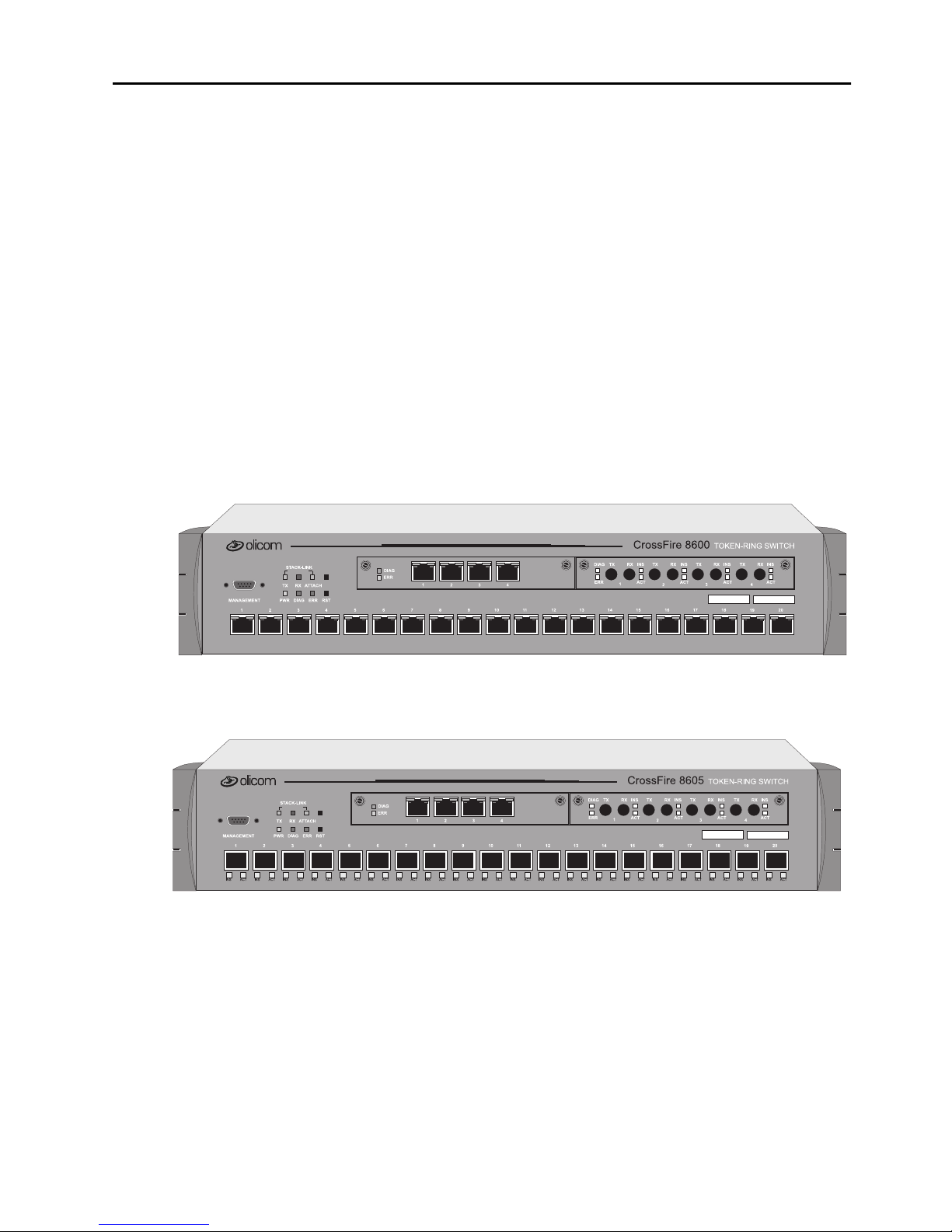
The figures below display a front view of the CrossFire 8600 Token-Ring Switch
and the Cross Fire 8605 Token-Ring Fiber Switch.
1
Figure 1. CrossFire 8600 Token- R ing Swit ch
Figure 2. CrossFire 8605 Token- R ing Fi ber Sw it ch
CrossFire 8 600/8605 Toke n-Ring S witches v. 1.2, P/N: 710001 641 Ove rvie w and Specifications

2
Switching Technology
Demand for network bandwidth continues to grow, driven by the increasing
number of systems used i n network-i ntens ive appl icat ions. LAN segmenta tio n has
been the prevalent method for addressing these demands and has been further
popularized by trends toward server centralization. However, the implementation
costs o f LA N s eg m en tation , as w el l as the re al perf o r ma n ce charac teristi cs of
conventional network components, have served to limit growth of some TokenRing networks. Alternative technologies for addressing bandwidth demands
present yet other inhibitors, usually relating to costs. Token-Ring switching
provides users with an easy, cost-effective technique for addressing these demands.
Token-Rin g swit che s, suc h a s th e C ros sFire 8600 and the CrossF ir e 8605, in crease
throughput between Token-Ring segments by supporting simultaneous, parallel
conversations. Switched connections between Token-Ring segments last only for
the durati on of the packet—new connecti ons can be made between diff erent
segments for the next pack et.
Token-Ring switches solve congestion problems caused by high-bandwidth
devices an d powerful appli ca tions as well as the number of users. Therefore, each
of these de vices—serve rs, for ex ample—can be as signed it s own 16 Mbps s egment.
In Token-Ring networks, the major bottleneck is typically the throughput to highbandwidth de vice s such a s serve rs, a nd betwe en r outers , bridg es, and swi tches. An
effective solution is full-duplex communication, an option for each segment
connected to a CrossFire 8600 or a CrossFire 8605 port. Normally, Token-Ring
operates in ha lf-duplex communication mode, which means stations can either
receive or transmit. With full-dup lex technology, two commun icating stations can
tran sm i t an d re ce iv e at the sa m e ti m e . W h en pa ck ets can fl ow in b ot h di re ctions
simultaneously, effective Token-Ring bandwidth doubles from 16 Mbps to 32 Mbps.
The CrossFir e 8600 and the CrossFir e 8605 can forward Token-Ring frames among
multiple, shared or dedicated Token-Ring LAN segments. Using a frame
forwarding te chnique simila r to t hat of a mult iport Token-R ing trans pare nt bri dge,
the switch us es Toke n-Ring MAC addresses to forwa r d Toke n-Ring frames from
any of its ports to any other.
Switch of Switches
The Cross Fire 8600 and the Cr ossFir e 8605 can be deployed i n a varie ty of network
configurat ions, all o f whi ch prov ide a si gnifi cant in crease in networ k pe rforma nce.
The series of Olic om Token-Ring products allows users to buil d network systems
that can transport data efficiently and scale upwards as throughput requirements
incre ase. T he swit ches d eliver high- relia bilit y and med ia flex ibilit y. The se fe atures
combine to allow the switches to be used as a switch of switches which provides
media flexibility in an Token-Ring configuration.
CrossFire 8600/8605 Token-Ring Switches v. 1.2, P/N: 710001641 Overview and Specifications

The CrossFi re 8600 an d the Cros sFire 86 05 can easily c onnect wi th oth er CrossFire
products to deliver a broad range of netwo rk carrying ca pacity. Band width is ea sily
scaled to meet all performanc e r equirements.
Switch of Servers
With client/server applications, many client workstations may attempt to access a
single server at the same time. This traffic pattern may create bottlenecks at the
server. To furthe r enhance performance, the CrossFire 8600 and the CrossFire 8605
can deliver dedicated bandwidth to high-spe ed file servers. All servers perform
better with dedicated 16 Mbps bandwi dth.
Even better performance can be achieved by installing multiple adapters in the
server . By connecting these adapters to the switch, multiple 16 Mbps paths to the
server are created, a solution tha t is only possible when using a s witch.
The switch ties together all Token-Ring devices lined to a local wiring center. In
networks , where a significan t portion of the traffic move s locally between client
and server, the switch can be very effective .
3
Switch of Hubs
When network traffic increases beyond the capability of hubs, contention results.
Applica tions suffer and may even fail. The net effect of such a network
configura tion is that all devices share a single 16 Mbps data path, thus redu cing
overall network efficiency. The CrossFire 8600 and CrossFire 8605 can be very
effective when used as a switch of hubs.
The switche s can alleviate conten tion through microsegmentat ion, or reducing the
number of dev i ces in each shared segment. To pro v ide microsegm en tation, the
switch es divid es a s ing le 16 Mb ps s egmen t into mu ltipl e 1 6 Mbps s egment s. As an
example, a workgroup has 16 Mbps of capacity. The 20 ports on the switches
support 10 simulta neous conver sations wit h 20 hub s, thus pro viding t he workgroup
with 160 Mbps bandwidth throughput , which results in a signi ficant gain in
bandwidth.
Switch of Desktops
The CrossFire 8600 and th e CrossFire 8605 are a cost-effe ctive means of pr oviding
dedica ted bandwidth to individual des ktop workstations . In this application, the
switch replaces a hub, providing excellent, hub-like network management
statis tics. Tot al network capacity a nd through put increa se dramatic ally for at tached
desktop workstations.
CrossFire 8 600/8605 Toke n-Ring S witches v. 1.2, P/N: 710001 641 Ove rvie w and Specifications

4
Switch of Floors and Buildings
For networ k manage rs, mul tist ore y bui ldi ngs an d cam puses c an rep rese nt a uni que
networking ch allenge. How can a network manager provide an efficient LAN
intercon nect for use rs tha t ar e located on seve ral floo rs of a buildi ng or in differen t
buildings ?
Token-Ring switching and the CrossFire product family can provide the best
solutio n. The CrossFire 8600 and the Cros sFire 8605 pr ovide enh anced throughp ut
to local wiring closets th at can be connected to a switch located in the data center.
Many networks consist of users located in different buildings of a campus
environment. The switches can be used as a co llapsed backbone interconnecting
multiple buildings of a campus. They can provide the connectivity solution and
enhanced throughput that such campus environments require.
Switch of Routers
Router technology has had a significant impact on the design of today’s
internet works. Routers have become t he cornerst one of mos t product ion ne tworks.
Although well equipped to provide firewall, WAN connectivity, security, and
connection be tween dissimila r LANs, routers are una ble to provid e high throughput
between desk top devices and servers . Because of these li mi tations, rout ers and
switches perform complimentary fun ctions in the network.
The C rossFi re 8600 a nd t he CrossFire 8605 can be used as a front -en d to rout ers t o
increase performance in each subnet. Communication between local clients and
servers is enhanced at the workgroup le vel below the router .
The switches ca n also be used to back-end rout ers. In networks were many routers
are inte rconnected over Toke n-Ring and backbo ne performance is not acceptable,
the switches provide non-blocking communic ation between the routers for
enhanced network performance. This provides protoc ol transparency with
enhanced throughput in each subnet between local servers and desktops, thus
allowing network managers to build logical networks as large as network layer
protocol and broadcast traffic allow.
The SwitchProbe (Switched Port Analyzer) also gives a colla ps ed backbone
network superi or network managemen t and the abil ity to perform protocol analys is
from a single loc ation . The Switc hProbe (Swi tch Port Ana lyze r) provi des the lat est
technology for monitoring switch-based networks and helps to reduce the cost of
managi ng the s e netw or ks.
CrossFire 8600/8605 Token-Ring Switches v. 1.2, P/N: 710001641 Overview and Specifications
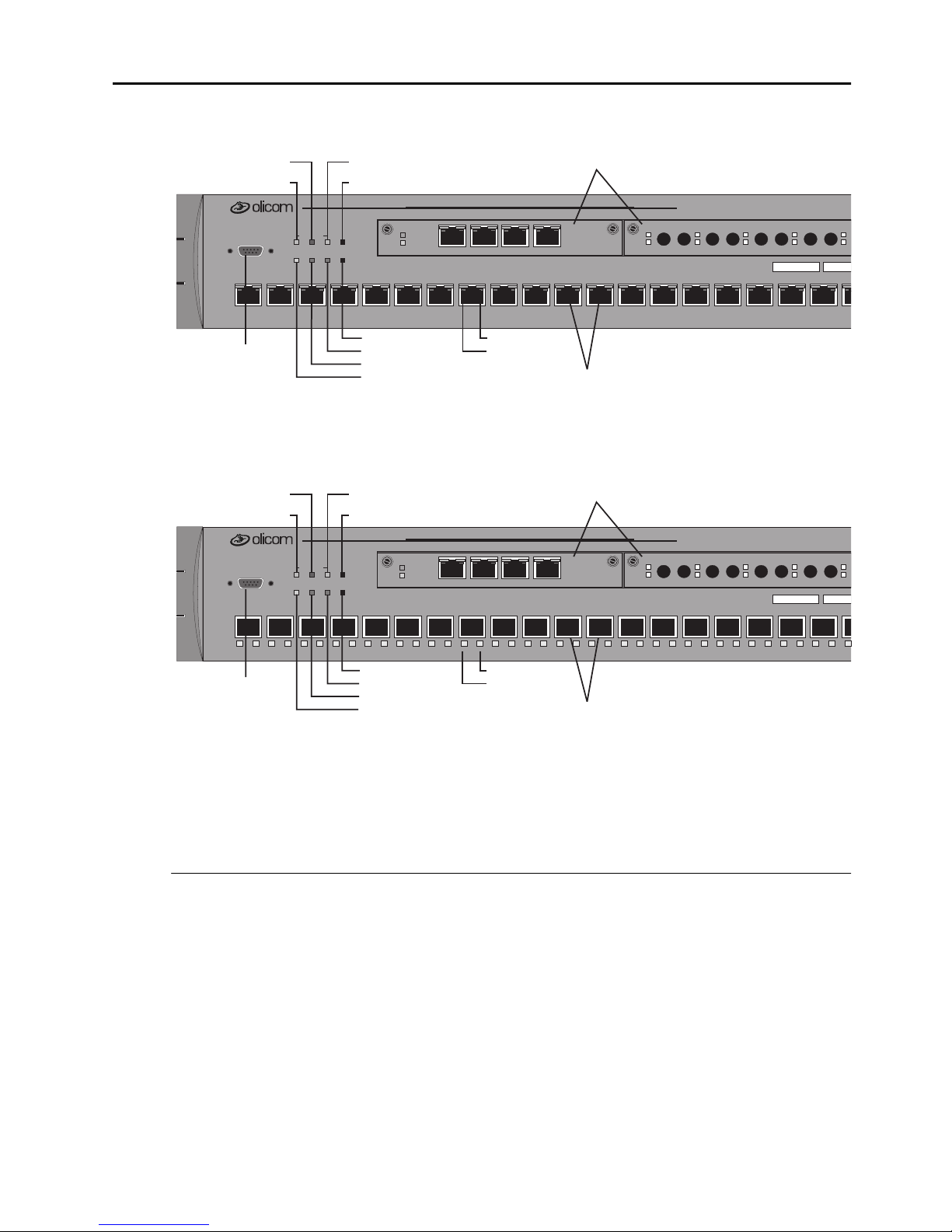
Physical Characteristics
I
I
I
5
2 Expansion modules
ERR
1
20 Token-Ring UTP/STP ports
CrossFire 8600
TXTX RX TXRX
2
TOKEN-RING SW
RX TX RX INS
INSINSINSDIAG
3
18
STACK-LINK TX LED
MANAGEMENT
1
MANAGEMENT port
(Out-of-Band
Management)
STACK-LINK
RXTX
DIAGPWR RSTERR
32
ATTAC H
STACK-LINK ATTACH LEDSTACK-LINK RX LED
SysReq button
5
4
RST button (reset)
ERR LED
DIAG LED
PWR LED
DIAG
ERR
1
234
876109 151211 1413 1716
Port ACT LED
Port INS LED
Figure 3. Location of LEDs, Switches, and Connector s on CrossFire 8600
2 Expansion modules
ERR
CrossFire 8605
TXTX RX TXRX
1
2
TOKEN-RING SW
TOKEN-RING SW
RX TX RX INS
INSINSINSDIAG
3
18
18
STACK-LINK TX LED
MANAGEMENT
1
1
STACK-LINK
RXTX
DIAGPWR RSTERR
32
32
ATTAC H
STACK LINK ATTACH LEDSTACK-LINK RX LED
SysReq button
5
5
4
4
DIAG
ERR
1
234
876109 151211 1413 1716
876109 151211 1413 1716
ACTACTACTACT
4
19
ACTACTACTACT
4
19
19
INS ACT INS ACT INS ACT INS ACT INS ACT INS ACT INS ACT INS ACT INS ACT INS ACT INS ACT INS ACT INS ACT INS ACT INS ACT INS ACT INS ACT INS ACT INS ACT INS
MANAGEMENT port
(Out-of-Band
Management)
RST button (reset)
ERR LED
DIAG LED
PWR LED
Port ACT LED
Port INS LED
20 Token-Ring Fi portsber
Figure 4. Location of LEDs, Switches, and Connector s on CrossFire 8605
Out-of-Band Management (OBM)
The 9-pin, mal e, Out-of-Band Manage ment (OBM) port labelle d MANAGEMENT
functions as a DTE port.
This port enables attachment o f a ter minal, either loc al or rem ote, thro ugh a modem
connection. The terminal can be used to configure and moni tor the switch.
The Out-of-B and Man agement port automatically detects the baud rat e of the
term i nal to wh ich it is attach ed.
CrossFire 8 600/8605 Toke n-Ring S witches v. 1.2, P/N: 710001 641 Ove rvie w and Specifications

6
Token-Ring Ports
•
CrossFire 8600
Twenty s hielded RJ-45 connectors for Tok en-Ring connection.
— Support for the IBM Cabling System via 150 ohm, shielded twisted-pair
(150 ohm STP); or 100 or 120 ohm unshielded twi st ed-pair via Category
3, 4, or 5 cables.
— These po rts allo w half-du plex (HDX) or full-dupl ex (FDX) connections to
other switch es , hubs, or end nodes.
•
CrossFire 8605
Twenty fiber VF-45 connectors for Token-Ring co nnec tion.
— These po rts allo w half-du plex (HDX) or full-dupl ex (FDX) con nections to
other switch es, hubs, or end nodes.
•
The switch will automatically sense what type of Toke n-Ring connection is
being employed on each of its ports, whether it is a connection:
— to a shared-media segment via a Token-Ring concentrator (Sta tion mode)
— to another Token-Ring switch
— operating at 4 Mbps or at 16 Mbps
— to a dedicate d-media segment, directly to a Token-Ring LAN station
operating in half-duple x or full-duplex mode (Port mode)
The switch will au tomatic ally c onfigure (re quiring no ope rator a ction) e ach po rt to
operate at the highest level of capability possible. No special cro ssover cables are
required for Token-Ring stations on dedicated-media segments or for switch-toswitch conne ctions; the same straight t hrough cablin g is used regard less of the typ e
of connection. This auto-sens e/auto-configure capability of the switch can be
overridden by explicit console management.
Switched Port Analyzer
Any of the twenty Token-Ri ng ports can be configured as a TokenProbe port. It is
used to monitor any one of the other Token-Ring ports so that the activity can be
traced by a special passive network analyzer attached to the TokenProbe port.
CrossFire 8600/8605 Token-Ring Switches v. 1.2, P/N: 710001641 Overview and Specifications

Universal Expansion Slots and Modules
The switch contains two universal expansion slots (see Fi gure 3 or Figure 4) that
will accommodate optional, field-installable Universal Expansion Modules
(UEMs) that provide additiona l connections. Future UEMs will provide the
foll owing types of connections:
•
OC-8610 4-Port Token-Ring UTP/STP
•
OC-8611 4-Port Token-Ring Fiber
•
OC-8320 ATM155 LANE Bridge UTP
•
OC-8321 ATM155 LANE Bridge MMF
•
OC-8650 High-Speed Token-Ring UTP
•
OC-8651 High-Speed Token-Ring MMF
7
Reset Button
The switch has a recessed rese t button labelled RST that is located on the front
panel. Pressing the reset button resets the hardware and software and clears all
tables and memory, in cludin g the address tabl es. Press ing the rese t button doe s not
clear thos e val ues stored in non-volatile random access memory (NVRAM).
System Request Button
This unlabel led recesse d button is locat ed on the front panel abo ve the reset button.
Pressi ng the button causes the
device attached to the MANAGEMENT port. Pressing the button for more than
five seconds will initiate a modem download of the main image.
➽ Note:
personnel. The button is recessed to prevent accidental activation.
Labels
The two labels in the right side of the front panel are :
System Request
The system request button should be used only at the direction of service
menu to appea r on the console
•
The MAC Address Label:
The unique glob ally assigned base Base MA C-Address of the switch.
•
The S w it ch N u mb er Lab e l:
Blank label for an individual user identification of the switch.
CrossFire 8 600/8605 Toke n-Ring S witches v. 1.2, P/N: 710001 641 Ove rvie w and Specifications

8
Status and Activity LEDs
The switch featur es three status LEDs on the front pa nel that show the current status
of the switch. Also on the front panel are three LEDs that show activity for the
optional stacker link module. In additio n, each Token-Ring port has two LEDs. On
CrossFir e 8600, these two LEDs are unlabe lled and located on the upper edge of
each port. On C ross Fire 8 605, the se LEDs a re l ocated und er e ach port and la belle d
ACT and INS.
Refer to Figure 3 and Figure 4 in this chapter for the locations of all the LEDs.
Table 1 below lists the st atus LEDs and their meanings.
LED State Meaning
PWR
DIAG
ERR
Off
On
On
Blinking
On
The switch is not connected to a power outlet, or
the po wer supply is faulty.
The switch is receiving power.
The DIAG diagnostics LED is on duri ng the
power-on self-test.
During download of a new software image, the
DIAG LED blinks to indic ate the clearing ( slow
blink) and loa ding (faster blink) of F LASH
memory.
The ERR LED is off during normal operation. If
the LED turns on, an error has occurred. Power
the switch down and up again. The ERR LED
should not t urn on again. If it does, the switch is
faulty.
Note that the ERR LED also tur ns on if the s witch
is powered only by an exte rnal power supply.
Table 1. Status LEDs and Thei r Meanings
The stack-link LEDs and port LEDs are describe d in the tables on the next page.
CrossFire 8600/8605 Token-Ring Switches v. 1.2, P/N: 710001641 Overview and Specifications

Table 2 lists the stack-link LEDs and their meanings.
LED State Meaning
9
TX
RX
ATTACH
Table 2. Stac k-link LEDs and Their Meani ngs
or
On
blinking
or
On
blinking
On
Data is being transmitted to the stack link. It is
blinking, when the stack interface is inserted.
Data is being received from the stack link. It is
blinking, when the stack interface is inserted.
A connection has be en established to the stack.
Table 3 lis ts the port LEDs and their meanings .
LED State Meaning
INS
On
Th e Token- R ing po r t is in s er ted in to the ri ng.
(left LED of
port)
Off
Blinking
The Token-Ring por t is not inserted into the ring.
The Token-Ring port is disabled.
ACT
(rig ht LED of
or
On
blinking
Data is being transmitted to or received from the
port.
port)
Table 3. Port LEDs and Their Meanings
CrossFire 8 600/8605 Toke n-Ring S witches v. 1.2, P/N: 710001 641 Ove rvie w and Specifications

10
Features and Specifications
Features a nd spec ifications for t he CrossFire 8600 and the CrossFir e 8605 are listed
below.
Feature s
Performance and Advanced Fe atures
•
Three switching modes:
— Low latency cut-through
— Store and Forward
— Auto (Adaptive cut-through)
•
Enhanced bridging modes:
— Transparent Bridging
— Sour c e Ro u t e S w it ch i n g
— Source Route Bridging (SRB)
— Source Route Transparent Bridging (SRT )
•
Support for dup licate MAC address schemes
•
Automatic port sensing of operating mode and media speed
•
Multiple Token-Ring port operation modes:
— Half-duplex concentrator and station
— Full-d uplex concentr ator and station (Dedi cated Token-Ring)
— RI/RO-like connecti o n
•
Spanning Tre e Protocol support:
— IEEE 802.1D
— IBM Spanning Tree Protocol
•
CrossLink high-speed inter-switch connection
(up to 256 Mbps using eight ports)
•
Advanced filte ring (MAC add res s / Protocol)
•
VLAN support
•
Support for transmission pri orities
•
Congestion control
CrossFire 8600/8605 Token-Ring Switches v. 1.2, P/N: 710001641 Overview and Specifications

Management
•
Extensive and sophis ticated netw ork management:
— SNMP management
— Out-of-band management via Telnet and VT100 consoles
— Graphical m anagement ap plicatio n for HP OpenV iew for W indo ws 95 an d
Windo ws NT (for i nformation on a ddit ional management appli catio ns for
Unix, please contact your local Olicom sales represen tative)
•
Support for RMON and standard MIBs
•
Network statistics
•
LAN probe port mirroring
•
Fault isolation and detection
•
Download via TFTP or X-modem of new switch microcode
11
•
Up- and download of switch configuration via TFTP
Scalability and High Availability
•
Up to 5,500 active LAN stations per group of four ports (1-4, 5-8, 9-12,
13-16, 17-20) with a maximum of 10,000 active LAN stations per switch
•
Stackable architecture
•
Optional redundant power supply
•
High density switch with seamless integration of LAN & ATM via LAN
emulation bridging
Installation
•
No sp ecial cro s so ver cab le requ ir e d
•
Rack or surface mount ing
•
Plug and Play for transpa rent forwarding:
— Automatic learning of network configuration
— Transparent to high-level protocol
•
Automatic sensing and configuration of ports
•
A factory-ass igned MAC address (the switch can also be configured with a
loca ll y adminis t er ed M AC addr e ss )
CrossFire 8 600/8605 Toke n-Ring S witches v. 1.2, P/N: 710001 641 Ove rvie w and Specifications

12
Specifications
The tables on the following pages list the product specifications for the CrossFire
8600 and the CrossFire 8605.
Capacity
Specification Value
Number of Token-Ring ports
(base configuration)
Maximum number of
additional Token-Ring ports in
expansion modules
Number of Token-Ring
switc hes in sta ck
Maximum number of TokenRing ports in stack
2 Expansion slots, choice of
20
8
8 using the CrossFire 8300 Switch Stacker
5 using the CrossFire 8635 Internal Stacker
Module
2 using the CrossFire 8630 Stacker Link
Module
224 using the CrossFi r e 8300 Switch Stacker
140 usi ng the CrossFire 8635 Internal St acker
Module
56 using the CrossFire 8630 Stacker Link
Module
4 x 4/16 Mbps RJ-45 Token-Ring
4 x 4/16 Mbps Fiber Token-Ring
1 x ATM155 Card (UTP and MMF)
2 x High-Speed Token-Ring (UTP and Fiber)
Global lookup table size
(stations and bridges)
Local lookup table size, tot al for
4 ports
(stations and bridges)
Maximum n umbe r
of logical ri ngs
Maximum number of VLANs
Table 4. Capacity Specifications
CrossFire 8600/8605 Token-Ring Switches v. 1.2, P/N: 710001641 Overview and Specifications
10,000
5,500
63
63

Performance
Specification V alue
13
Maximum frame rate per port
Maximum aggrega te frame rate
per 4 ports
Throughput per port
Aggregate switching rat e
(uni cast o r br oadca st) for e ntir e
switch
With in switch latency
(cut-through)
Table 5. Performance Specifications
Physical Characteristics
Specification Valu e
57,000 pps in each di rection (measured with a
frame size of 19 bytes)
200,000 pps in eac h direction. Full media
speed for frame sizes abov e 28 bytes
16 Mbps in each directi on for all f rame s izes
1,500,000 pps for sma llest frame sizes
35 µs
Rack mount
Dimensions
19" rack mount (hardware included)
Width: 19" (48.3 cm)
Depth: 15.74" (40.0 cm)
Height 3.46" (8.80 cm)
Weight
Power
Frequency
AC cu rrent ra t in g
Thermal dissipation
(witho ut modules)
MTBF CrossFire 8600
19.4 lbs. (8.8 Kg)
100 to 240 VAC autosensing
50/60 Hz
1.5 A @ 120 V; 0.75 A @ 220 V
CrossFire 8600:
CrossFire 8605
: 80 W
: 77,240 hours
CrossFire 8605:
Table 6. Specifications of Physical Characteristics
90 W
40,342 hours
CrossFire 8 600/8605 Toke n-Ring S witches v. 1.2, P/N: 710001 641 Ove rvie w and Specifications

14
Specification Value
Operating Temperature:
Non-operating Temperature:
Humidity:
Operating
Non-operating
Electromagnetic emiss ion s
certification
Safety
MANAGEMENT port
Software updates
Protocol compatibility
10 to 40°C (50 to 104°F)
-10 to 70°C (13 to 158°F)
8 to 80% (non-condensing)
90% @ 45°C (113°F)
FCC Class A
EN55022 Class A
VCCI Class A
UL1950
CSA C22.2 No. 950
EN60950
TIA/EIA-232-F, DB9 male connector
Flash PROM, TFTP, X-modem
Transparen t to higher layer pr otocols
Spanning Tree Protocol
support
MIBs supported
IEEE 802.1D complian t
IBM Spanning Tree
SNMP MIB II (RFC1213)
SR Bridge MIB (RFC1525)
Bridg e MIB (RFC1493)
Evol ution of the Interfac es Group of MIB- II
(RFC1573 )
RMON MIB/TR extensions - selected
groups only (RFC1757/1513)
IEEE 802.5 MIB (RFC1749/1748)
IEEE 802.5r DTR MIB
IEEE 802.5r DTR MAC MIB
oc8600 unit MIB
VTP MIB
Table 6. Specifi cations of Physical Characteri stics
CrossFire 8600/8605 Token-Ring Switches v. 1.2, P/N: 710001641 Overview and Specifications
 Loading...