

Page 1
DOC-6951/1.2
CrossFireTM 8600/8605
Token-Ring Switches
Guide to Operations
Page 2

Page 3

CrossFireTM 8600/8605
Token-Ring Switches
Guide to Operations
Page 4

ii
CLASS 1 LASER PRODUCT
Trademarks
GoCard and the Oli com clasped hands l ogo are registered trademarks of Olicom A/S. CellDriver,
ClearServer, ClearSession, ClearSight, CrossFire, LANscout, PowerMACH, RapidFire and RapidLAN
are trademarks of Olicom A/S. C learCare, Clear Partner, ClearS tep and Expert Wat ch are service marks
of Olicom A/S. Olicom is a registered trademark. Other brand and product names are trademarks,
registered trademarks, service mar ks or registered service marks of their res pective holders.
Copyrights
Olicom A/S reserves the r ight to modify the i nf ormation given in this publication without prior notice.
The warranty terms and conditions applicable for your purchase of this equipment are given at the time
of purchase. Please consult your place of purchase for details.
Publicat ion: DOC-6951 v. 1.2
Part Number : 710001641
© Copyright Olicom A/S,
All rights reserved
transmitted in any form or by any means, without the prior written permission of the publisher.
Denmark, November 1998
. No part of this publication may be reproduced, stor ed in a retrieval system, or
FCC Compliance
This equipment has been tested and found to comply with the limits for a Class A digital device, pursuant
to Part 15 of th e FCC Ru les. T hes e limit s are des ign ed to pr ovi de reaso nab le prot ecti on ag ainst harmf ul
interference when the equipment is operated in a commercial environment. This equipment generates,
uses and can rad iate radio frequency energy and, if not installed and used in accordance wit h the
instructi on manual, may cause har m f ul interference to radio communicati ons. Operation of this
equipment in a re sidential area is likely to cause harmful in terference in which ca s e the user will be
required to correct the interference at his own expens e.
Warning:
interference in which case the user may be re quired to take adequa te measures.
This device complies with part 15 of the FCC Rules. Operation is subject to the following two
conditions : (1) This device may not cause harmful interference, and ( 2) this device must accept any
interference received, including interfer e nce that may cause undesired operation.
This is a Class A product. In a domestic environment this product may cause radio
Declaration of Conformity
We Olicom A/S
Nybrovej 114
DK-2800 Ly ngby
Denmark
declare und er our sole responsibility that the pr oducts
CrossFire 8600 Token-Ring Switch and/or CrossFire 8605 Token-Ring Fiber Switch
to which this declaration relates are in conformity with the following standards or other normative
documents
EN 50082-1
EN 55022
EN 60950 including Amendments
EN 60825-1
following the provisions of 89/336/EEC Dir ective and 73/2 3/EEC Directive.
CrossFire 8600/8605 Token-Ring Switches v. 1.2, P/N: 710001641
Page 5

Modifications
If the device is changed or modified w ithout the ex press approval of Olicom A/S the user may void his
or her authority to operate the equipment.
Safety No tic e s
➽
To avoid shock hazard, do not connect or disconnect any cables or perform inst allation,
Danger:
maintenance, or reconfiguring of the CrossFire 8600 Token-Ring Switch and/or the CrossFire 8605
Token-Ring Fiber Switch during an electrical storm.
iii
➽
➽
➽
To avoid the possibility of electrical shock, switch power off and unplug the power cord from
Danger:
the outlet before detaching the power cord from th e CrossFire 8600 Token-Ring Switch and/ or the
CrossFire 8605 Token-Ring Fiber Switch.
Do not open the CrossFire 8600 Token-Ring Switch and/or the CrossFire 8605 Token-Ring
Danger:
Fiber Swi tch. Dangerous voltages insid e.
To avoid shock hazard the power cord must be connected to a prop erly wired and earthed
Danger:
receptacl e. Any equipment to which the CrossFir e 8600 Token-Ring Switch and/or the CrossFire 860 5
Token-Ring Fiber Switch will be attached must also be connected to properly wired and earthed
receptacles.
Caution:
Observe the following pow er cable considerations before you begin installation of the CrossFire 8600
Token-Ring Switch and/or the CrossFire 860 5 Token-Ring Fiber Switch.
1. The socket out let shall be installed near the equipment and shall be easily accessible.
2. To prevent electrical shock, the power cord set used must comply with national regulations.
2a. The female rece ptacle of the cord must meet CEE-22 requirements .
2b. The cord must be UL listed, CSA lab elle d , and cons ist of th ree condu cto rs with a maxi mum
of 15 feet in length.
Type SVT or SJT cord sets shall be used for units which stand on a desk or tab le. Type SJT
cord sets sh all be used for units which stand on floor.
2c. The male plug fo r un its operating at 115 VA C shall consist of a parallel blade, gro unding
type attach ment plug rated 15 A, 125 VAC.
The male plug fo r units operating at 230 V A C s hall consist of a tandem blade, grounding
type attach ment plug rated 15 A, 250 VAC.
The male plug fo r units operating at 230 V A C (outside of the United States and Canada) s hall
consist of a grounding type attachment plug rat e d 15 A, 250 VAC and have the appropriate
safety approvals for the countr y in which the equipment will be install ed.
➽
Caution:
Switch while you are installing the unit to avoid dropping it on the floor or any equipment beneath it in
the rack . The C rossF ire 860 0 Tok en- Ri ng Sw itc h un it and th e Cr ossF ire 86 05 Tok en- Ring Fi ber Swi tch
unit each weighs approximately 8.8 kg (19.4 lbs).
Support the CrossFire 8600 Token-Ring Switch and/or t he CrossFire 8605 Token-Ring Fiber
➽
Warning:
local area netw orkin g ( L A N ) .
CrossF ire 8600/8605 Token-Ring Switches v. 1.2, P/N: 710001641
All RJ45 connectors must only be connected to safety extra low voltage (SELV) circuits like
Page 6

iv
CrossFire 8600/8605 Token-Ring Switches v. 1.2, P/N: 710001641
Page 7

Table of Contents
1. Overview and Specifications 1
Switching Technology . . . . . . . . . . . . . . . . . . . . . . . 2
Switch of Switches . . . . . . . . . . . . . . . . . . . . . . . 2
Switch of Servers. . . . . . . . . . . . . . . . . . . . . . . . 3
Switch of Hubs . . . . . . . . . . . . . . . . . . . . . . . . . 3
Switch of Desktops. . . . . . . . . . . . . . . . . . . . . . . 3
Switch of Floors and Buildings . . . . . . . . . . . . . . . . . 4
Switch of Routers. . . . . . . . . . . . . . . . . . . . . . . . 4
Physical Characteristics . . . . . . . . . . . . . . . . . . . . . . 5
Out-of-Band Management (OBM) . . . . . . . . . . . . . . . 5
Token-Ring Ports. . . . . . . . . . . . . . . . . . . . . . . . 6
Switched Port Analyzer. . . . . . . . . . . . . . . . . . . . . 6
Universal Expansion Slots and Modules . . . . . . . . . . . . 7
Reset Button . . . . . . . . . . . . . . . . . . . . . . . . . . 7
System Request Button . . . . . . . . . . . . . . . . . . . . 7
Labels . . . . . . . . . . . . . . . . . . . . . . . . . . . . . 7
Status and Activity LEDs . . . . . . . . . . . . . . . . . . . . 8
Features and Specifications . . . . . . . . . . . . . . . . . . . 10
Features . . . . . . . . . . . . . . . . . . . . . . . . . . . 10
Specifications. . . . . . . . . . . . . . . . . . . . . . . . . 12
v
2. Switch Theory of Operation 17
How the CrossFire 8600 and the CrossFire 8605 Works . . . . 17
Multiple Simultaneous Conversations . . . . . . . . . . . . 18
Low Latency . . . . . . . . . . . . . . . . . . . . . . . . . 1 9
Address Management . . . . . . . . . . . . . . . . . . . . 19
Multiple Bridging Modes . . . . . . . . . . . . . . . . . . . 20
Filtering. . . . . . . . . . . . . . . . . . . . . . . . . . . . 22
Congestion Control. . . . . . . . . . . . . . . . . . . . . . 2 3
Three Switching Modes . . . . . . . . . . . . . . . . . . . 23
Token-Ring Port Operation Modes. . . . . . . . . . . . . . 24
RI/RO-Like Connection. . . . . . . . . . . . . . . . . . . . 24
Transmission Priority Queues . . . . . . . . . . . . . . . . 25
CrossLink Connections. . . . . . . . . . . . . . . . . . . . 2 5
Spanning Tree Protocol Support . . . . . . . . . . . . . . . 2 5
VLAN Support . . . . . . . . . . . . . . . . . . . . . . . . 26
Management . . . . . . . . . . . . . . . . . . . . . . . . . 2 7
RMON Support. . . . . . . . . . . . . . . . . . . . . . . . 28
Built-in Port Counters. . . . . . . . . . . . . . . . . . . . . 29
Stackable Architecture . . . . . . . . . . . . . . . . . . . . 30
CrossF ire 8600/8605 Token-Ring Switches v. 1.2, P/N: 710001641
Page 8

vi
Optional Redundant Power Supply . . . . . . . . . . . . . .30
Benefits of the CrossFire 8600 and the CrossFire 8605. . . . . .32
3. Preparing for Installation 43
Safety Recommendations . . . . . . . . . . . . . . . . . . . . .43
Safety with Electricity . . . . . . . . . . . . . . . . . . . . .43
Preventing Electrostatic Discharge Damage . . . . . . . . .45
Site Requirements. . . . . . . . . . . . . . . . . . . . . . . . .46
Environment . . . . . . . . . . . . . . . . . . . . . . . . . .46
Chassis Accessibility . . . . . . . . . . . . . . . . . . . . .46
Cooling and Airflow . . . . . . . . . . . . . . . . . . . . . .46
Power . . . . . . . . . . . . . . . . . . . . . . . . . . . . .46
Unpacking and Inspecting . . . . . . . . . . . . . . . . . . . . .48
Rules to Remember . . . . . . . . . . . . . . . . . . . . . . . .49
Frame Length Limit . . . . . . . . . . . . . . . . . . . . . .49
Cables and Distances between Devices . . . . . . . . . . .49
Sample Applications for the CrossFire 8600 and
the CrossFire 8605 . . . . . . . . . . . . . . . . . . . . . . . .50
Important Management Considerations . . . . . . . . . . . .54
4. Installation 55
Required Network Preparation - Frame Length Limit . . . . . . .55
Installation Summary . . . . . . . . . . . . . . . . . . . . . . .56
Unpacking Instructions. . . . . . . . . . . . . . . . . . . . . . .57
Materials Needed for Installation . . . . . . . . . . . . . . . . .57
Installing a Universal Expansion Module . . . . . . . . . . . . .58
Mounting the Chassis . . . . . . . . . . . . . . . . . . . . . . .59
Rack or Cabinet Mounting. . . . . . . . . . . . . . . . . . .59
Table-Mounting . . . . . . . . . . . . . . . . . . . . . . . .60
Cabling. . . . . . . . . . . . . . . . . . . . . . . . . . . . . . .61
Connecting Devices to the Token-Ring Ports . . . . . . . . .61
Connecting Devices to the Token-Ring Ports
Using Building Wiring . . . . . . . . . . . . . . . . . . . . .62
Checking the Installation. . . . . . . . . . . . . . . . . . . . . .63
Applying Power . . . . . . . . . . . . . . . . . . . . . . . . . .64
Control Panels . . . . . . . . . . . . . . . . . . . . . . . . . . . 66
Front Panel . . . . . . . . . . . . . . . . . . . . . . . . . .66
Back Panel. . . . . . . . . . . . . . . . . . . . . . . . . . .68
5. Connecting a Network Management Console 69
Connecting the Console . . . . . . . . . . . . . . . . . . . . . .69
Communication Problems . . . . . . . . . . . . . . . . . . .71
Diagnostic Screen . . . . . . . . . . . . . . . . . . . . . . .72
CrossFire 8600/8605 Token-Ring Switches v. 1.2, P/N: 710001641
Page 9

vii
6. Switch Configuration 75
General Guidelines. . . . . . . . . . . . . . . . . . . . . . . . 76
Navigating within the Menus . . . . . . . . . . . . . . . . . 77
Main Menu . . . . . . . . . . . . . . . . . . . . . . . . . . . . 78
Configuration.... . . . . . . . . . . . . . . . . . . . . . . . 78
Statistics... . . . . . . . . . . . . . . . . . . . . . . . . . . 7 8
Download/Upload... . . . . . . . . . . . . . . . . . . . . . 78
Reset.... . . . . . . . . . . . . . . . . . . . . . . . . . . . 7 8
Exit Console . . . . . . . . . . . . . . . . . . . . . . . . . 78
Configuration Menu . . . . . . . . . . . . . . . . . . . . . . . 79
Switch Configuration Screen . . . . . . . . . . . . . . . . . . . 81
Stack Configuration Screen . . . . . . . . . . . . . . . . . 84
Module Information Screen. . . . . . . . . . . . . . . . . . 85
VLAN Configuration . . . . . . . . . . . . . . . . . . . . . . . 87
VLAN Configuration Menu . . . . . . . . . . . . . . . . . . 88
VLAN Configuration Screen . . . . . . . . . . . . . . . . . 8 9
VLAN Param e te r C o n figuration fo r T r C RF Screen. . . . . . 90
VLAN P a rameter C o n figuration for T r BRF Scre e n . . . . . . 92
Local VLAN Port Configuration Screen . . . . . . . . . . . 93
IP Configuration Screen . . . . . . . . . . . . . . . . . . . . . 9 4
BootP Requests and Parameters . . . . . . . . . . . . . . 96
SNMP Configuration Menu. . . . . . . . . . . . . . . . . . . . 9 7
Spanning Tree Protocol . . . . . . . . . . . . . . . . . . . . . 97
IEEE 802.1D Spanning Tree Protocol (STP). . . . . . . . . 9 8
Spanning Tree for TrBRF Screen . . . . . . . . . . . . . . 99
Spanning Tree for TrCRF Screen . . . . . . . . . . . . . . 10 1
Port Spanning Tree Parameters Screen . . . . . . . . . . .103
Current Spanning Tree Information Screen . . . . . . . . .104
Port Configuration Screen . . . . . . . . . . . . . . . . . . . .105
Switched Port Analyzer Menu . . . . . . . . . . . . . . . . . .109
CrossLink. . . . . . . . . . . . . . . . . . . . . . . . . . . . .109
CrossLink Menu . . . . . . . . . . . . . . . . . . . . . . .111
CrossLink Configuration Screen . . . . . . . . . . . . . . . 112
Setting up a CrossLink . . . . . . . . . . . . . . . . . . . .113
Current CrossLink Information Screen. . . . . . . . . . . .114
Address Filtering . . . . . . . . . . . . . . . . . . . . . . . . .115
Filters and Port Security Menu . . . . . . . . . . . . . . . .116
Configure Filters Screen . . . . . . . . . . . . . . . . . . .117
Configure Port Security Mode Screen . . . . . . . . . . . .119
View Port Filters Screen . . . . . . . . . . . . . . . . . . .120
Protocol Filters Menu. . . . . . . . . . . . . . . . . . . . .121
Protocol Class Assignment Screen . . . . . . . . . . . . . 122
Port Filtering Attributes Screen . . . . . . . . . . . . . . . .12 3
CrossF ire 8600/8605 Token-Ring Switches v. 1.2, P/N: 710001641
Page 10

viii
Address Aging . . . . . . . . . . . . . . . . . . . . . . . . . . 125
Address Aging Menu . . . . . . . . . . . . . . . . . . . . 126
Port Address Table Aging Screen. . . . . . . . . . . . . . 127
Master Address Table Aging Screen . . . . . . . . . . . . 128
Password Menu . . . . . . . . . . . . . . . . . . . . . . . . . 129
Console/Telnet Sessions . . . . . . . . . . . . . . . . . . . . 130
Console Configuration Menu . . . . . . . . . . . . . . . . 130
Serial Link Configuration Screen . . . . . . . . . . . . . . 131
Creating a Console Session Using a Modem . . . . . . . . 132
Stopping the Console Session. . . . . . . . . . . . . . . . 132
Telnet Configuration Screen. . . . . . . . . . . . . . . . . 133
Telnet Sessions Screen . . . . . . . . . . . . . . . . . . . 134
Starting the Telnet Session . . . . . . . . . . . . . . . . . 135
Stopping the Telnet Session. . . . . . . . . . . . . . . . . 135
Involuntary Termination of the Telnet Session . . . . . . . 135
Download/Upload Menu . . . . . . . . . . . . . . . . . . . . . 137
Serial Link Download Screen . . . . . . . . . . . . . . . . 138
TFTP. . . . . . . . . . . . . . . . . . . . . . . . . . . . . 139
TFTP Download/Upload Screen. . . . . . . . . . . . . . . 139
Reset Screen . . . . . . . . . . . . . . . . . . . . . . . . . . 142
7. Monitoring the Network with the Console 145
Navigating Within the Menus . . . . . . . . . . . . . . . . . . 146
Statistics Menu. . . . . . . . . . . . . . . . . . . . . . . . . . 147
Switch Statistics Screen . . . . . . . . . . . . . . . . . . . 148
Port Status Screen. . . . . . . . . . . . . . . . . . . . . . 150
Port Statistics Menu . . . . . . . . . . . . . . . . . . . . . 152
General Statistics Screen . . . . . . . . . . . . . . . . . . 153
802.5 Statistics Screen . . . . . . . . . . . . . . . . . . . 156
802.5 State Information Screen . . . . . . . . . . . . . . . 159
802.5 DTR MAC Information Menu . . . . . . . . . . . . . 160
TXI Information Screen . . . . . . . . . . . . . . . . . . . 161
Station-CPort Information Screen . . . . . . . . . . . . . . 163
Address Tables Menu . . . . . . . . . . . . . . . . . . . . 165
Master Address Table Screen. . . . . . . . . . . . . . . . 166
Master Route Descriptor Table Screen . . . . . . . . . . . 168
VLAN Address Table screen . . . . . . . . . . . . . . . . 170
VLAN Route Descriptor Table Screen. . . . . . . . . . . . 171
Current Spanning Tree Information Screen . . . . . . . . . 172
Current Spanning Tree Information for a TrCRF Screen . . 175
VLAN Statistics . . . . . . . . . . . . . . . . . . . . . . . 178
VLAN Statistics Screen for TrCRF. . . . . . . . . . . . . . 178
VLAN Statistics Screen for TrBRF. . . . . . . . . . . . . . 179
CrossFire 8600/8605 Token-Ring Switches v. 1.2, P/N: 710001641
Page 11

ix
Diagnostic Test Results Screen . . . . . . . . . . . . . . .18 0
Message Log Information Screen . . . . . . . . . . . . . .181
Display Summary Screen . . . . . . . . . . . . . . . . . .182
8. Monitoring the Network with SNMP 183
SNMP Setup . . . . . . . . . . . . . . . . . . . . . . . . . . .183
IP Configuration Screen . . . . . . . . . . . . . . . . . . . . .18 3
SNMP Configuration . . . . . . . . . . . . . . . . . . . . . . .184
SNMP Configuration Screen . . . . . . . . . . . . . . . . .184
Community Strings Screen. . . . . . . . . . . . . . . . . .185
Trap Receivers Screen. . . . . . . . . . . . . . . . . . . .18 7
List of Supported Traps from a Switch . . . . . . . . . . . . 188
9. Monitoring Port Traffic 193
10. Troubleshooting 195
Obtaining Service . . . . . . . . . . . . . . . . . . . . . .195
Troubleshooting in a Network . . . . . . . . . . . . . . . .19 5
Start of Troubleshooting Process . . . . . . . . . . . . . .19 5
Choosing a Troubleshooting Procedure . . . . . . . . . . .196
11. Getting in Touch with Technical Support 201
Before You Contact Olicom Technical Support . . . . . . . . . 201
Hotline Support. . . . . . . . . . . . . . . . . . . . . . . . . .201
Fax Support . . . . . . . . . . . . . . . . . . . . . . . . . . .20 2
Bulletin Board Service . . . . . . . . . . . . . . . . . . . . . .202
Standard Modem Requirements . . . . . . . . . . . . . . . 202
ISDN Modem. . . . . . . . . . . . . . . . . . . . . . . . .202
Internet E-Mail . . . . . . . . . . . . . . . . . . . . . . . . . . 203
Anonymous Internet FTP Server. . . . . . . . . . . . . . . . .203
Internet World Wide Web Server (WWW) . . . . . . . . . . . .203
Olicom Support WEB. . . . . . . . . . . . . . . . . . . . . . .203
Problem Report Form . . . . . . . . . . . . . . . . . . . . . .204
Appendix A. Abbreviations 207
Appendix B. Cable and Pin Information 211
Connecting to the Out-of-Band Management Port . . . . . .21 1
Out-of-Band Management Port and Cable Pin-Ou ts . . . . . 212
Twisted-Pair Cable Pin Outs . . . . . . . . . . . . . . . . .214
Cabling Recommendations. . . . . . . . . . . . . . . . . .21 5
Cable Length and Lobe Wiring Rules for Dedicated-Media
LAN Segments . . . . . . . . . . . . . . . . . . . . . . . .217
CrossF ire 8600/8605 Token-Ring Switches v. 1.2, P/N: 710001641
Page 12

x
Cable Length and Lobe Wiring Rules for Shared-Media
LAN Segments. . . . . . . . . . . . . . . . . . . . . . . . 219
CrossFire 8600/8605 Token-Ring Switches v. 1.2, P/N: 710001641
Page 13

List of Figures
Figure 1. CrossFire 8600 Token-Ring Switch . . . . . . . . . . . . . 1
Figure 2. CrossFire 8605 Token-Ring Fiber Switch . . . . . . . . . . 1
Figure 3. Location of LEDs, Switches, and Connectors on
CrossFire 8600 . . . . . . . . . . . . . . . . . . . . . . . 5
Figure 4. Location of LEDs, Switches, and Connectors on
CrossFire 8605 . . . . . . . . . . . . . . . . . . . . . . . 5
Figure 5. Multiple Conversations Through a CrossFire 8600
or CrossFire 8605 Switch . . . . . . . . . . . . . . . . . 18
Figure 6. Typical Configuration with Switches Using
Multiple Bridging Modes . . . . . . . . . . . . . . . . . . 20
Figure 7. A Switch Configured with Two VLANs. . . . . . . . . . . 2 6
Figure 8. Typical LAN Segmentation . . . . . . . . . . . . . . . . 50
Figure 9. A Simple Application of the Switch . . . . . . . . . . . . 51
Figure 10. Typical Network without the CrossFire Switches . . . . . 52
Figure 11. Relieving the Overstressed Bac kbone. . . . . . . . . . . 5 2
Figure 12. Replacing SRBs with CrossFire 8600 or CrossFire 8605 . 53
Figure 13. Star-Wired Topology of Interconnec ted Switches . . . . . 54
Figure 14. Removing the Universal Expansion Slot Cover . . . . . . 58
Figure 15. Exposin g the Rack Mounting Brac ket . . . . . . . . . . . 59
Figure 16. Mounting the Switch in a Rack or Cabinet. . . . . . . . . 60
Figure 17. Connecting Devices to Token-Ring Ports . . . . . . . . . 6 2
Figure 18. Connec ting using Buildi ng Wiring . . . . . . . . . . . . . 63
Figure 19. The Back Panel of the Switch . . . . . . . . . . . . . . . 64
Figure 20. View of Console Connection—the MANA GE M ENT port . 70
Figure 21. Switch with four VLANs . . . . . . . . . . . . . . . . . . 87
Figure 22. Setting up CrossLinks . . . . . . . . . . . . . . . . . . . 109
Figure 23. TIA/EIA 232 Null-Modem Cable for the 25-pin Connector. 213
Figure 24. TIA/EIA 232 Null-Modem Cable for the 9-pin Connector . 213
Figure 25. Straight-Through Cable . . . . . . . . . . . . . . . . . . 214
Figure 26. Data Connector-to-RJ-45 Straight-Through Cable . . . . 214
xi
CrossF ire 8600/8605 Token-Ring Switches v. 1.2, P/N: 710001641
Page 14

xii
List of Tables
Table 1. Status LEDs and Their Meanings. . . . . . . . . . . . . . 8
Table 2. Stack-link LEDs and Their Meanings . . . . . . . . . . . . 9
Table 3. Port LEDs and Their Meanings . . . . . . . . . . . . . . . 9
Table 4. Capacity Specifications . . . . . . . . . . . . . . . . . . . 12
Table 5. Performance Specifications. . . . . . . . . . . . . . . . . 13
Table 6. Specifications of Physical Characteristics . . . . . . . . . 13
Table 7. Supported MIBs. . . . . . . . . . . . . . . . . . . . . . . 27
Table 8. Token-Ring Port Operation Modes . . . . . . . . . . . . . 32
Table 9. Switching Modes . . . . . . . . . . . . . . . . . . . . . . 34
Table 10. Expansion Module Slots . . . . . . . . . . . . . . . . . . 35
Table 11. Multiple Bridging Modes . . . . . . . . . . . . . . . . . . 36
Table 12. Spanning Tree Protocol. . . . . . . . . . . . . . . . . . . 37
Table 13. Management . . . . . . . . . . . . . . . . . . . . . . . . 38
Table 14. Network Monitoring . . . . . . . . . . . . . . . . . . . . . 39
Table 15. Filtering . . . . . . . . . . . . . . . . . . . . . . . . . . . 40
Table 16. Connectivity Options . . . . . . . . . . . . . . . . . . . . 41
Table 17. Front Panel Connectors and Push-Buttons . . . . . . . . . 66
Table 18. Front Panel LEDs . . . . . . . . . . . . . . . . . . . . . . 67
Table 19. Back Panel Switches and Connectors . . . . . . . . . . . 68
Table 20. Console Configuration Settings. . . . . . . . . . . . . . . 70
Table 21. Modem Settings. . . . . . . . . . . . . . . . . . . . . . 132
Table 22. Changing and Saving Switched Port Analyzer Settings . 194
Table 23. Symptom, LED State and Recommended Procedure . . 196
Table 24. Connecting to the Management Port . . . . . . . . . . . 211
Table 25. Pin-out of the Management Port . . . . . . . . . . . . . 212
Table 26. Copper Cable Types . . . . . . . . . . . . . . . . . . . 215
Table 27. Multimode Optical Fiber Cable Types. . . . . . . . . . . 215
Table 28. Lobe Length for 150 Ohm Shielded Media . . . . . . . . 217
Table 29. Lobe Lengths for 100 Ohm Shielded or Unshielded Cable 217
Table 30. Lobe Lengths for 100 or 120 Ohm Shielded or
Unshielded Cable . . . . . . . . . . . . . . . . . . . . . 218
Table 31. Lobe Lengths for Recommended Fiber Cable . . . . . . 218
Table 32. Alternate Optical Fibers. . . . . . . . . . . . . . . . . . 218
CrossFire 8600/8605 Token-Ring Switches v. 1.2, P/N: 710001641
Page 15

About this Manual
This manual is intended for network technicians familiar with the installation and
operation of net w orking equipment. It contains all the information requi red to
install and operate the CrossFire
8605 Token-Ring Fiber Switch.
Unless one of th e switche s is menti oned alone , the informat ion in t his guide appl ies
to both CrossFire 8600 and Cros sFire 8605.
The manual contains the following chapters and appendices.
TM
8600 Token-Ring Switch and/or the CrossFire
xiii
Chapter 1, “Overview and Specifications”
, is an overview of Token- Ring. It
explains how t he switc h is u sed i n a Tok en-Ring. In clu ded in t he chapt er is a lis t of
features and specifications.
Chapter 2, “Switch Theory of Operati on”
, explains how the switch improves
network performance.
Chapter 3, “Preparing for Installation”
Chapter 4, “Installation”
, contains instructions for installing, connecting and
, deals with preparing for installation.
verifying the operation of the switch.
Chapter 5, “Connecting a Network Management Console”
, explain s how t o se t
up a console connection for in-band or out-of-band switch management.
Chapter 6, “Switch Configuration”
, deals with setting up and configuring the
switch using a direct console connection.
Chapter 7, “Monitoring the Network with the Console”
, explains how to
monitor the switch using out-of-band management through a direct consol e
connection.
Chapter 8, “Monito ring the Net work with S NMP”
, explains ho w to monit or the
switch from a Network Management System using an application that supports
Simple Network Manage me nt P r otocol.
Chapter 9, “Monitoring Port Traffic”
, explains how to monitor ports on the
switch using SwitchProbe.
Chapter 10, “Troubleshooting”
, gives troubleshooting hints that can be used to
locate and reso lve minor problems.
Chapter 11, “Getting in Touch with Technical Support”
, lists Olic om’s support
services suc h as hotline support, fax support and the support web, as well as other
services such as bulletin board service, FTP server and e-mail.
Appendix A, “Abbreviations”
CrossF ire 8600/8605 Token-Ring Switches v. 1.2, P/N: 710001641
, lists the abbreviations used in this manual.
Page 16

xiv
Appendix B, “Cable and Pin Information”
, lists cables and cable types that can
be used with CrossFire Token-Ring equipment.
❏
CrossFire 8600/8605 Token-Ring Switches v. 1.2, P/N: 710001641
Page 17
1. Overview and Specifications
This chapter di scusses switching technology and how the CrossFire 8600 TokenRing Switch and/or the CrossFire 8605 Token-Ring Fiber Switc h can be used to
improve networ k performance. This chapter al so includes a list of features and
specif ications for the switch.
The topics of this chapter are presented under the following titles:
•
“Switching Technology”, starting on page 2.
•
“Physical Char acteristics ”, starting on page 5.
•
“Features and Speci fications”, starting on page 10.
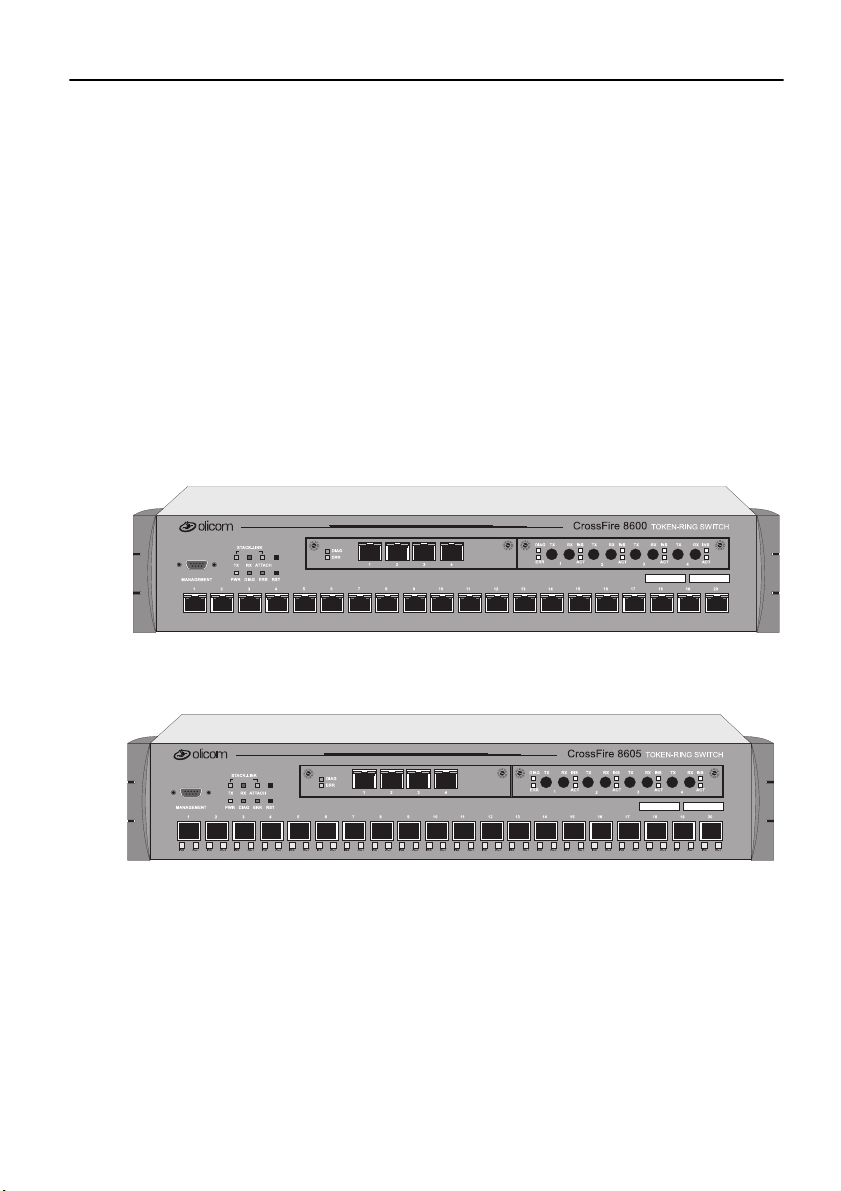
The figures below display a front view of the CrossFire 8600 Token-Ring Switch
and the CrossFire 8605 Token-Ring Fiber Switch.
1
Figure 1. CrossFi re 8600 Token-Ring Switch
Figure 2. CrossFi re 8605 Token-Ring Fiber Switch
CrossF ire 8600/8605 Token-Ring Switches v. 1.2, P/N: 710001641 Over view and Specifi cations
Page 18

2
Switching Technology
Demand for network bandwidth continues to grow, driven by the increasing
number of systems us ed in net work-inte nsive applic ations . LAN segmen tatio n has
been the prevalent method for addressing these demands and has been further
popularized by tre nds toward server centralization. However, the implementation
costs of LA N s eg mentation , as w el l as the real per fo r mance char ac te r ist i cs of
conventional network components, have served to limit growth of some TokenRing networks. Alternative technologies for addressing bandwidth demands
present yet other inhibitors, usually relating to costs. Token-Ring switching
provides users with an easy, cost-effective technique for addressing these demands.
Token-Ring s wit ches, s uch a s th e C rossFi re 8600 and the CrossFi re 8 605, in cre ase
throughput between Token-Ring segments by supporting simultaneous, parallel
conversations. Switched connections between Token-Ring segments last only for
the duration of the packet—new connections can be made betwe en different
segments for the next packet.
Token-Ring switches solve congestion problems caused by high-bandwidth
devices and powerful applications as well as the number of users. Therefore, each
of these devic es—servers , for example —can be assi gned its own 16 Mbps seg ment.
In Token-Ring networks, the major bottlene ck is typically the throughput to highbandwidth devi ces suc h as servers , and be tween r oute rs, b ridg es, and s witc hes. An
effective solution is full-duplex communication, an option for each segment
connected to a CrossFire 8600 or a CrossFire 8605 port. Normally, Token-Ring
operates in half-duplex communication mode , which means stations can either
receive or transmit. With ful l-duplex technolog y, two communicating stations can
transm i t an d re ce ive at the sa me ti m e . W h en pa ckets can flow in b ot h di re ct i on s
simultaneously, effective Token-Ring bandwidth doubles from 16 Mbps to 32 Mbps.
The CrossFire 8600 and the CrossFire 8605 can forward Token-Ri ng frames among
multiple, shared or dedicated Token-Ring LAN segments. Using a frame
forwarding techn ique si milar to t hat of a mult iport Tok en-Ring t ranspa rent bri dge ,
the switch uses Token-Ring MAC addresses to forward Token-Ring frames from
any of its ports to any other.
Switch of Switches
The CrossFire 8600 and the Cr ossFire 8 605 can be dep loyed in a variety of network
configuration s, all o f whi ch provide a s i gnifica nt in cre ase in ne twor k perform ance .
The series of Olicom Toke n-Ring products allows users to build network systems
that can transport data efficiently and scale upwards as throughput requirements
increas e. The s witche s del iver hig h-rel iabil ity an d media flex ibilit y. The se featu res
combine to allow the switches to be used as a switch of switches which provides
media flexibility in an Token-Ring configuration.
CrossFire 8600/8605 Token-Ring Switches v. 1.2, P/N: 710001641 Overview and Specifications
Page 19

The CrossFire 8600 and t he Cross Fire 8605 can e asily conne ct with other CrossFire
products to de liver a broa d range of networ k carrying capacit y. Bandwidth is easily
scaled to meet all performance requirements.
Switch of Servers
With client/server applications, many client workstations may attempt to access a
single server at the same time. This traffic pattern may create bottlenecks at the
server. To further enha nce performance, the CrossFire 8600 and the CrossFire 8605
can deliver dedic ated bandwidth to high-spe ed file servers. All servers perform
better with ded ica ted 16 Mbps bandwidth.
Even better performance can be achieved by installing multiple adapters in the
server. By connecting these adapters to the switch, multiple 16 Mbps paths to the
server ar e created, a solution that is on ly possible when using a switch.
The switch ties together all Token- Ring devices lined to a loc al wiring center. In
networks, wher e a significant portion of the traffic moves locally between client
and server, the switch can be very effective.
Switch of Hubs
When network traffic increases beyond the capability of hubs, contention results.
Applications suffer and may even fail. The net effect of such a network
configuration is that all devices share a single 16 Mbps data path, thus reducing
overall network efficiency. The CrossFire 8600 and CrossFire 8605 can be very
effective when used as a switch of hubs.
3
The switches ca n alleviate contention through microsegmentation , or reducing the
number o f devices i n each shared segment. To p r o v ide micro segmentat io n, the
switches divid es a sing le 16 Mbps segmen t i nto mult ipl e 16 Mbps se gment s. As a n
example, a workgroup has 16 Mbps of capacity. The 20 ports on the switches
support 10 s imultaneo us conver sations wit h 20 hubs, t hus pro viding the workgroup
with 160 Mbps bandwidt h throughput, which results in a s ignificant gain in
bandwidth .
Switch of Desktops
The CrossFire 8600 and the CrossFir e 8605 are a c ost-effecti ve means of pr oviding
dedicate d bandwidth to individual desktop workstations. In this applicat ion, the
switch replaces a hub, providing excellent, hub-like network management
statisti cs. Total network ca pacity and t hroughput increase dr amaticall y for atta ched
desktop workstations.
CrossF ire 8600/8605 Token-Ring Switches v. 1.2, P/N: 710001641 Over view and Specifi cations
Page 20

4
Switch of Floors and Buildings
For network mana gers , multis t orey bui ldings and c ampuses c an represe nt a unique
networking chal lenge. How can a network manager provide an ef ficient LAN
interconnec t for users that ar e lo cated on s everal floors of a buildi ng or in differen t
buildings?
Token-Ring switching and the CrossFire product family can provide the best
solution. T he CrossFire 8600 and the CrossFi re 8605 pr ovide enhanc ed throughput
to local wiring closets that can be connected to a switch located in the data center.
Many networks consist of users located in different buildings of a campus
environment. The switches can be used as a collapsed backbone interconnecting
multiple buildings of a campus. They can provide the connectivity solution and
enhanced throughput that such campus environments require.
Switch of Routers
Router technology has had a significant impact on the design of today’s
internetworks. Rout ers ha ve be come the cor nerst one of m ost pro ductio n networks .
Although well equipped to provide firewall, WAN connectivity, security, and
connection betwe en dissimilar LANs, routers are unable to provide hi gh throughput
between desktop de vices and servers. Because of these limitations, routers and
switches perform complimentary functions in the network.
The Cross Fire 8600 and t he CrossFire 8605 can be used as a front-en d to routers to
increase performance in each subnet. Communication between local clients and
servers is enhanced at the workgroup level below the router.
The switches can also be used to back-end routers. In networks were many route rs
are intercon nected over Token-Ring and backbone performance is not acceptable,
the switches provide non-blocking communication between the rout ers for
enhanced network performance. This provides prot ocol transparency with
enhanced throughput in each subnet between local servers and desktops, thus
allowing network managers to build logical networks as large as network layer
protocol and broadcast traffic allow.
The SwitchProbe (Switched Port Analyzer) also gives a collapsed backbone
network superior net work management and the abilit y to perform protoc ol analysis
from a singl e loc ation . The SwitchPr obe (Swi tc h Port Ana ly zer) p rovi des the l atest
technology for monitoring switch-based networks and helps to reduce the cost of
man ag ing the s e networks.
CrossFire 8600/8605 Token-Ring Switches v. 1.2, P/N: 710001641 Overview and Specifications
Page 21
Physical Characteristics
I
I
I
5
2 Expansion modules
ERR
1
20 Token-Ring UTP/STP ports
CrossFire 8600
TXTX RX TXRX
2
TOKEN-RING SW
RX TX RX INS
INSINSINSDIAG
3
18
STACK-LINK TX LED
MANAGEMENT
1
MANAGEMENT port
(Out-of-Band
Management)
STACK-LINK
RXTX
DIAGPWR RSTERR
ATTACH
32
STACK-LINK ATTACH LEDSTACK-LINK RX LED
SysReq button
5
4
RST button (reset)
ERR LED
DIAG LED
PWR LED
DIAG
ERR
1
234
876109 151211 1413 1716
Port ACT LED
Port INS LED
Figure 3. Location of LEDs, Switches, and Connectors on CrossF ire 8600
STACK LINK ATTACH LEDSTACK-LINK RX LED
STACK-LINK
RXTX
DIAGPWR RSTERR
ATTACH
32
32
SysReq button
5
5
4
4
RST button (reset)
ERR LED
DIAG LED
PWR LED
DIAG
ERR
1
234
876109 151211 1413 1716
876109 151211 1413 1716
Port ACT LED
Port INS LED
STACK-LINK TX LED
MANAGEMENT
1
1
INS ACT INS ACT INS ACT INS ACT INS ACT INS ACT INS ACT INS ACT INS ACT INS ACT INS ACT INS ACT INS ACT INS ACT INS ACT INS ACT INS ACT INS ACT INS ACT INS
MANAGEMENT port
(Out-of-Band
Management)
2 Expansion modules
20 Token-Ring Fi portsber
ERR
CrossFire 8605
TXTX RX TXRX
1
2
TOKEN-RING SW
TOKEN-RING SW
RX TX RX INS
INSINSINSDIAG
3
18
18
Figure 4. Location of LEDs, Switches, and Connectors on CrossF ire 8605
ACTACTACTACT
4
19
ACTACTACTACT
4
19
19
Out-of-Band Management (OBM)
The 9-pin, male, Out-of-Band Management (OBM) port labelled MANAGEMENT
functions as a DTE port.
This port enables atta chment o f a terminal, either local or remote , through a modem
connection . Th e terminal can be used to configure and moni tor the switch.
The Out-of-Band Manage ment port automatically detec ts the baud rate of the
termi nal to whic h it is attach ed.
CrossF ire 8600/8605 Token-Ring Switches v. 1.2, P/N: 710001641 Over view and Specifi cations
Page 22

6
Token-Ring Ports
•
CrossFire 8600
Twenty shielded RJ -45 connectors for Token-Ring connection.
— Support for the IBM Cabling System via 150 ohm, shielded twisted-pair
— These ports allow ha lf-duplex (HDX) or full -duplex ( FDX) connec tions to
•
CrossFire 8605
Twenty fiber VF-45 conn ec tors for T oken-Ring connection.
— These ports allow ha lf-duplex (HDX) or full -duplex ( FDX) connec tions to
•
The switch will automatically sens e what type of T oken-Ring connection is
being employed on each of its ports, whether it is a connection:
— to a shared-media segment via a Token- Ring concentrator (Sta tion mode)
— to another Token-Ring switch
— operating at 4 Mbps or at 16 Mbps
(150 ohm STP); or 100 or 120 ohm unshielded twisted-pai r via Category
3, 4, or 5 cables.
other switches, hubs, or end nodes.
other switches, hubs, or end nodes.
— to a dedicated-media segment, directly to a Token-Ring LAN station
operating in half-duplex or full-du plex mode (Port mode)
The switch will automat ical ly confi gure (re quiri ng no operat or action) e ach po rt t o
operate at the highe st level of capability pos sible. No special crossove r ca bles are
required for Token-Ring stations on dedicated-media segments or for switch-toswitch connect ions; the same straight through cablin g is used regardle ss of the type
of connection. This auto-sense/auto-configure capabilit y of the switch can be
overridden by explicit console management.
Switched Port Analyzer
Any of the twenty Token-Ring ports ca n be configured as a T okenProbe port. It is
used to monitor any one of th e other Token-Ring ports so that the ac tivity can be
traced by a special passive network analyzer attached to the TokenProbe port.
CrossFire 8600/8605 Token-Ring Switches v. 1.2, P/N: 710001641 Overview and Specifications
Page 23

Universal Expansion Slots and Modules
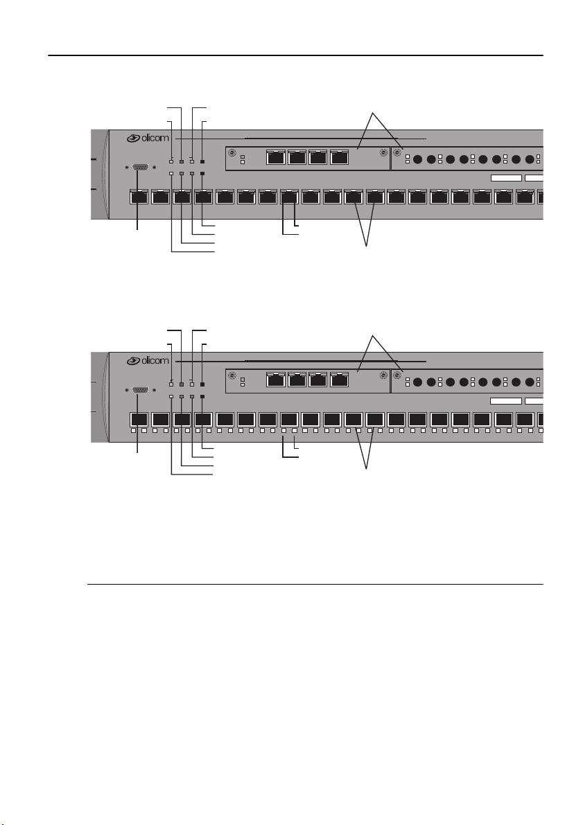
The switch contains two universal expansion slots (see Figure 3 or Figure 4) that
will accommodate optional, field-installable Universal Expansion Modules
(UEMs) that provi de a dditional connections . Future UEMs will provide the
following types of connections:
•
OC-8610 4-Port Token-Ri ng UTP/STP
•
OC-8611 4-Port Token-Ri ng F iber
•
OC-8320 ATM155 LANE Bridge UTP
•
OC-8321 ATM155 LANE Bridge MMF
•
OC-8650 High-Speed Token-Ring UTP
•
OC-8651 High-Speed Token-R ing MMF
Reset Button
The switch has a recessed reset button labelled RST that is located on the front
panel. Pressing the reset button resets the hardware and software and clears all
tables and memory, in cl uding the ad dress t ables. Pres sing the rese t but ton doe s not
clear those values stored in non-volatile random access memory (NVRAM).
7
System Request Button
This unlabell ed recessed butt on is located on th e front panel above the reset button.
Pressing the button causes the
device attached to the MANAGEMENT port. Pressing the button for more than
five seconds will initiate a modem download of the main image.
➽ Note:
The system request b utton should be used only at the dire ction of service
personnel. The button is recessed to prevent accidental activation.
System Request
menu to appear on the console
Labels
The two labels in the right side of the front pane l are:
•
The MAC Address Label:
The unique global ly as signed base Base MAC-Address of the switc h.
•
The Sw it ch N u mb er Lab el:
Blank label for an individual user identification of the switch.
CrossF ire 8600/8605 Token-Ring Switches v. 1.2, P/N: 710001641 Over view and Specifi cations
Page 24

8
Status and Activity LEDs
The switch featur es three status LEDs on the front panel that show the current statu s
of the switch. Also on th e front panel are three LEDs that show activity for the
optional stacke r link module. In additio n, each Token-Ring port has two LEDs. On
CrossFire 8600, these two LEDs are unlabelled and loca ted on the upper edge of
each port. On Cros sFir e 8605, thes e LEDs ar e locate d und er eac h port an d label led
ACT and INS.
Refer to Figure 3 and Figure 4 in this chapter for the locations of all the LEDs.
Table 1 below lists the status LEDs and their meanings.
LED State Meaning
PWR
Off
The switch is not connected to a power outle t, or
the powe r supply is faulty.
The switch is receiving power.
The DIAG diagnostics LED is on during the
DIAG
On
On
power - on self-test.
Blinking
During download of a new software image, the
DIAG LED blinks to indicate the clearing (slow
blink) and loading (faster blink) of FLASH
memory.
ERR
On
The ERR LED is off during normal operation. If
the LED turns on, an error has occurred. Power
the switch down and up again. The ERR LED
should not turn on ag ain. If it does, the switch is
faulty.
Note that the ERR LED also turn s on if the switc h
is powered only by an external power supply.
Table 1. Status LEDs and Their Meanings
The stack-link LEDs and port LEDs are described in the tables on the next page.
CrossFire 8600/8605 Token-Ring Switches v. 1.2, P/N: 710001641 Overview and Specifications
Page 25

Table 2 lists the stack-link LEDs and their meanings.
LED State Meaning
9
TX
RX
ATTACH
T able 2. Stack-link LEDs and Thei r M eanings
or
On
blinking
or
On
blinking
On
Data is being transmitted to the stack link. It is
blinking, when the stack interface is inserted.
Data is being received from the stack link. It is
blinking, when the stack interface is inserted.
A connection has been established to the stack.
Table 3 lists the port LEDs and their meanings.
LED State Meaning
INS
(left LED of
port)
ACT
(right L ED of
On
Off
Blinking
or
On
blinking
The Token- R ing port is inser t ed into the ring.
The Token-Ring port is not inserted into the ring.
The Token-Ring port is disabled.
Data is being transmitted t o or receiv ed from the
port.
port)
Table 3. Port LEDs and Their Meanings
CrossF ire 8600/8605 Token-Ring Switches v. 1.2, P/N: 710001641 Over view and Specifi cations
Page 26

10
Features and Specifications
Features and specifi cations fo r the CrossFire 86 00 a nd the C rossFire 8605 are li sted
below.
Feature s
Performance an d A dvanc ed Fe atures
•
Three switchin g mode s:
— Low latency cut-through
— Store and Forward
— Auto (Adaptive cut-through)
•
Enhanced bridging modes:
— Transparent Bridging
— Source Ro u t e S w it ch i n g
— Source Route Bridging (SRB)
— Source Route Transparent Bridging (SRT)
•
Support for duplic ate MAC address schem es
•
Automatic port sensing of operating mode and media speed
•
Multiple Token-Ring port operation modes:
— Half-duplex concentrator and station
— Full-duplex concentrator and station (Dedicated Token-Ring)
— RI/RO-l ike connection
•
Spanning Tree Protocol support:
— IEEE 802.1D
— IBM Spanning Tree Protocol
•
CrossLink high-speed inter-switch connection
(up to 256 Mbps using eight port s )
•
Advanced filtering (MAC address / Protocol)
•
VLAN support
•
Support for transm ission priorities
•
Congestion control
CrossFire 8600/8605 Token-Ring Switches v. 1.2, P/N: 710001641 Overview and Specifications
Page 27

Management
•
Extensive and sophisticated network management:
— SNMP management
— Out-of-band management via Telnet and VT100 consoles
— Graphical management applicatio n for HP OpenV ie w for W indo ws 95 and
Windo ws NT (for i nformat ion on addit ion al manag ement ap plica tions for
Unix, please contact your local Olicom sales representativ e)
•
Support for RMON and standard MIBs
•
Network statistics
•
LAN probe port mirroring
•
Fault isolation and detection
•
Download via TFTP or X-modem of new switch microcode
•
Up- and download of switch configuration via TFTP
Scalability and High Availability
•
Up to 5,500 active LAN stations per group of four ports (1-4, 5-8, 9-12,
13-16, 17-20) with a maximum of 10,000 active LAN stations per switch
11
•
Stackable architecture
•
Optional redundant power supply
•
High density swit ch with seamless integration of LAN & ATM via LAN
emulation brid ging
Installation
•
No special cross o ver c ab l e r eq u ir e d
•
Rack or surface mounting
•
Plug and Play for transparent f orwarding:
— Automatic learning of network configuration
— Transparent to high-level protocol
•
Automatic sensing and configuration of ports
•
A factory-assigned MAC address (the switch can also be configured with a
locall y a dm in i stered MAC addre s s)
CrossF ire 8600/8605 Token-Ring Switches v. 1.2, P/N: 710001641 Over view and Specifi cations
Page 28

12
Specifications
The tables on the following pages list the product specifications for the CrossFire
8600 and the CrossFire 8605.
Capacity
Specification Value
Number of Token-Ring ports
(base configuration)
Maximum number of
additional T oken-Ring ports in
expansion modules
Number of T oken-Ring
switches in stack
Maximum number of TokenRing ports in stack
2 Expansion slots, choice of
Global lookup table size
(stations and bridges)
20
8
8 using the CrossFire 8300 Switch Stacker
5 using the CrossFire 8635 Internal Stacker
Module
2 using the CrossFire 8630 Stacker Link
Module
224 using the CrossFire 8300 Switch Stacker
140 using t he CrossFire 8635 Internal St acker
Module
56 using the CrossFire 8630 Stacker Link
Module
4 x 4/16 Mbps RJ-45 Token-Ring
4 x 4/16 Mbps Fiber Token-Ring
1 x ATM155 Card (UTP and MMF)
2 x High-Speed T ok en-R ing (UTP and Fiber)
10,000
Local lookup table size, total f or
4 ports
(stations and bridges)
Maximum nu mber
5,500
63
of logical rings
Maximum number of VLANs
T able 4. Capacity Specifications
CrossFire 8600/8605 Token-Ring Switches v. 1.2, P/N: 710001641 Overview and Specifications
63
Page 29

Performance
Specification Value
13
Maximum frame rate per port
Maximum aggregate frame rate
per 4 ports
Throughput per port
Aggregate switching rate
(uni cast or bro adcast ) f or en tire
switch
Within switch latency
(cut-thr ough)
Table 5. Performance Specifications
Physical Characteristics
Specification Value
Rack mount
Dimensions
57,000 pps in each directi on (measured with a
frame size of 19 bytes)
200,000 pps in each dire ction. Full media
speed for frame sizes above 28 byte s
16 Mbps in each direction for all frame s izes
1,500,000 pps for smalle st frame sizes
35 µs
19" rack mount (hardware included)
Width: 19" (48.3 cm)
Depth: 15.74" (40.0 cm)
Height 3.46" (8.80 cm)
Weight
Power
Frequency
AC current ratin g
Thermal dissipation
(without modules)
MTBF Cros sFire 8600
Table 6. Specifications of Physical Characteristics
CrossF ire 8600/8605 Token-Ring Switches v. 1.2, P/N: 710001641 Over view and Specifi cations
19.4 lbs. (8.8 Kg)
100 to 240 VAC autosensing
50/60 Hz
1.5 A @ 120 V; 0.75 A @ 220 V
Cros sFire 8600:
Cros sFire 8605
90 W
: 80 W
: 77,240 hours
Cros sFire 8605:
40,342 hours
Page 30

14
Specification Value
Operating Temper atu re:
Non-operating Temperature:
Humidity:
Operating
Non-operating
Electromagn etic emissions
certification
Safety
MANAGEMENT port
Software updates
Protocol compatibility
Spanning Tree Protocol
support
MIBs supported
10 to 40°C (50 to 104°F)
-10 to 70°C (13 to 158°F)
8 to 80% (non-condensing)
90% @ 45°C (113°F)
FCC Class A
EN55022 Class A
VCCI Class A
UL1950
CSA C22.2 No. 950
EN60950
TIA/EIA-232-F, DB9 male connector
Flash PROM, TFTP, X-modem
Tr ans parent to higher layer protocols
IEEE 802.1D compliant
IBM Spanning Tree
SNMP MIB II (RFC1213)
SR Bridge MIB (RFC1525)
Bridge MIB (RFC1493)
Evoluti on of the Inte rfaces Group of MIB-II
(RFC1573)
RMON MIB/TR extensions - selected
groups only (RFC1757/1513)
IEEE 802.5 MIB (RFC1749/1748)
IEEE 802.5r DTR MIB
IEEE 802.5r DTR MA C MIB
oc8600 unit MIB
VTP MIB
Table 6. Specification s of Physical Characteristics
CrossFire 8600/8605 Token-Ring Switches v. 1.2, P/N: 710001641 Overview and Specifications
Page 31

Specification Value
15
Network management
Table 6. Specifications of Physical Characteristics
-
SNMP Management Platform
-
Console
-
Telnet sessions
-
Switch Manager for HP OpenView for
Window s 95 a n d NT
-
Included in Olicom ClearSight
Management Syste m
-
Additional management applications
avail able on Unix platforms:
—HP OpenView NNM for HP-UX
—Tivoli TME 10 NetView for AIX
❏
CrossF ire 8600/8605 Token-Ring Switches v. 1.2, P/N: 710001641 Over view and Specifi cations
Page 32

16
CrossFire 8600/8605 Token-Ring Switches v. 1.2, P/N: 710001641 Overview and Specifications
Page 33

17
2. Switch Theory of Operation
This chapter explains how the CrossFire 8600 Toke n-Ring Switch and/or the
CrossFire 8605 Token-Ring Fiber Switch improve network performance.
The topics of this chapter are presented under the following titles:
•
“How the Cros sFire 8600 and t he C rossFi re 8605 Works”, starti ng on page 17.
•
“Benefits of the CrossFire 8600 and the Cr ossFire 8605”, starting on page 32.
How the CrossFire 8600 and the CrossFire 8605 Works
The CrossFire 8600 and the CrossF ire 8605 are both IEEE 802.5 -compliant devices
designed to boost throughput on Token-Ring net works. They operate as a Media
Access Control (MAC)-layer device that is protocol independent.
This chapter describes how the switch operates as a single stand-alone unit. The
switch contains the followin g main element s, as listed below:
•
Switching Bus—t he arch ite cture of the s wit ch c enters ar ound the AXIS b us, a
520 Mbps switching fabric through which all switched ports communicate.
The AXIS bus is a partially asynchronous time division multiplexed bus used
for switching packets between heterogeneous LAN modules.
•
Token-Ring Ports—each port can attach to a classical Token-Ring segment or
to a dedicated sta tion. Now users running bas ic application s a r e able to share
bandwidth, and users running bandwidth-intens ive applications can receive
their own dedic ated 16 Mbps port. Each dedicated port can also be set up in
full-duplex communication mode, so that each 16 Mbps port doubles to 32
Mbps.
•
Expansion Modules—each switch supports two expansion modules. These
modules include RJ- 45 or fiber port s to provid e up to eight ad ditional 16 Mbps
ports, or high -speed conne ctions suc h as 155 Mb ps ATM, to provide tw o ATMRing connections for s ervers or backbone connectivity.
•
Stack Link Module—the switch su pports a stack lin k module t hat can be us ed
to connect two switches from the CrossFire 8600 series in a back-to-back
configuration. Alternatively, up to five switches can be connected together
using and internal s tacker module, and up to eight switches can be connected
together using the stack link module and an additional switch stack unit. By
connecting switches together through the stack link module, the switches
virtually c o mbine to form a single unit, providing scalability, simplified
management, and enhanced performance.
CrossF ire 8600/8605 Token-Ring Switches v. 1.2, P/N: 710001641 Switch Theory o f Operation
Page 34
18
Multiple Simultaneous Conversations
A limitation of Token-Ring is that it supports only one packet at a time . The
CrossFire 8600 and the CrossFire 8605 improve data th roughput by supporting
multiple, simultaneous, full-duplex conversations. By using High-Speed bus
switching technology, the switch creates multiple data paths. These switched
connections between Token-Ring segments last only for the duration of a byte
transmission. New connections are made “on-the-fly” between different ports on
the switch for the next byte.
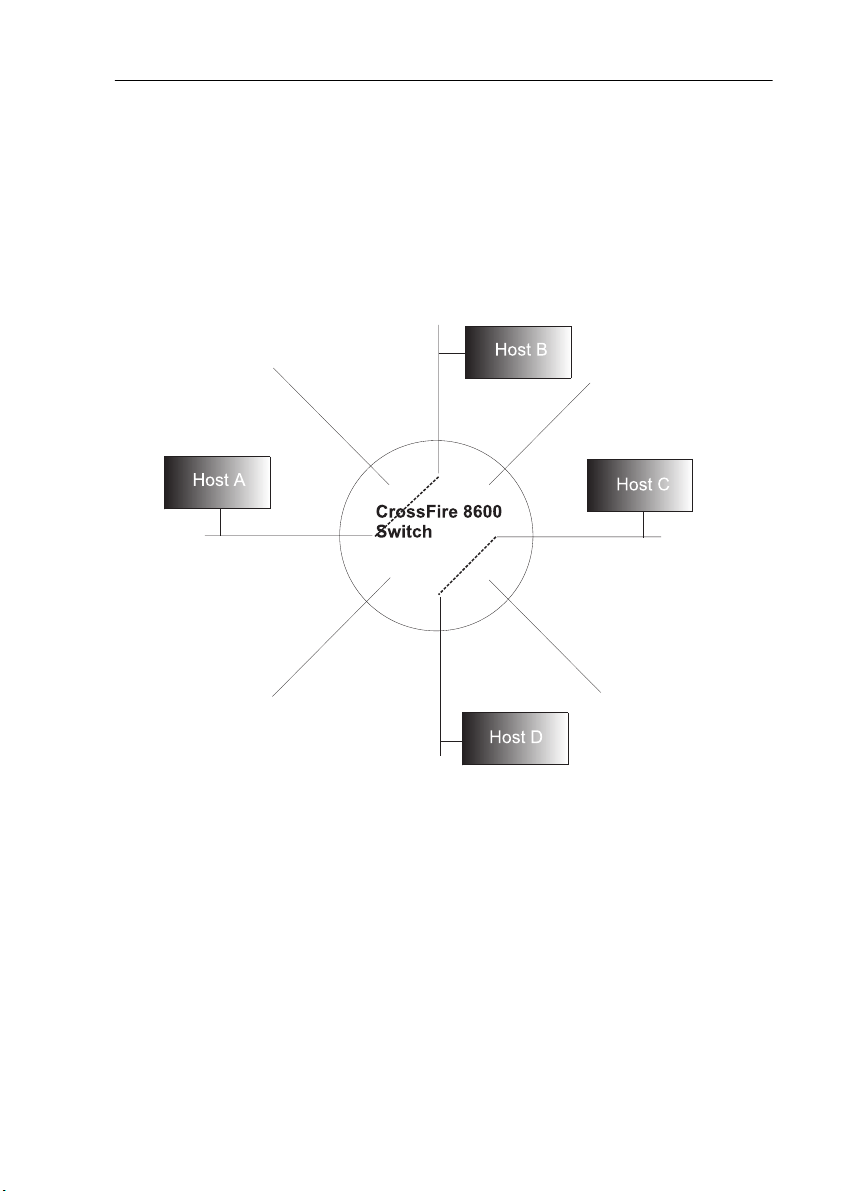
Figure 5. Multiple Conversations Thr ough a CrossFire 8600 or
CrossFire 8605 Swit ch
For example, as shown in Figure 5, while host A is transmitti ng a byte to host B,
the swi tch connects o nly the lines from A to B si nce th ere is no ne ed to send packet s
to all other ports. At the same time, a second switching circuit can connect host C
to host D. The result: Two packets are sent simultaneously.
➽ Note:
The switch transmit s broadca st and multic ast packet s on seve ral switc h ports
simultan eous ly.
The increase in thr oughput is directl y proportional to the number of physical toke nrings that are interconnected through the switch. A switch with 20 ports
interconnec ted provides up to ten concurrent paths. With ten simultaneous
CrossFire 8600/8605 Token-Ring Switches v. 1.2, P/N: 710001641 Switch Theory of Operation
Page 35

19
conversation s, the switch creates 1 60 Mbps th roughput in half-dup lex mode, or 320
Mbps throughput in full-duplex mode.
A single segment can be dedi cated t o a si ngle host or share d by sev eral. To optimize
throughput, high-speed servers can be given dedicated switch ports.
By transporting multiple Token-Ring packets simultaneously, it boosts overall
network throu ghput.
Low Latency
When operating in cut-through mode, the switch mi nimizes latency—the tim e it
takes to forwa rd a pack et from one T oken-Ri ng seg ment to another —by begi nning
switching i mmediatel y af ter look ing a t the fi rst six byt es of t he des tinat ion addre ss
in the pack et. If the packet needs to be swit ched to another LAN segment, its da ta
begins flowin g through the destination port before the entire packet has been
received. The res ult: packets can appear at the output port 35 microseconds after
entering the input port. Network devices that us e store-and-forward tech nology
introduce m uch longe r delay s becaus e they wait to re ceive the ent ire packet bef ore
forwarding it .
By minimizing delay, the switch can move more packets freely throughout the
LAN without degradi ng performance.
Address Management
At power up, the system address t ables do not contain any information. Wheneve r
a switch receives a packet wi th a n unknown s ource or de sti nation a ddres s, it le arn s
the new source address and stores its location in coming port in the address table.
If the dest ination a ddress i s unknown it sen ds the packe t to al l ports that can r eceive
data from the incoming port. When the res ponse packe t comes back, the s witch will
learn the responder’s location and adds it to the addre ss table. Once the address
table entries are created, th e switch uses these learn ed address to switch all
subsequent packets to the port where the destination address is located.
The system addres s table maintains up to 10, 000 entries, and each po rt address table
maintain s 5,500 acti ve Token -Rin g addres ses (ea ch port addre ss tabl e is sha red by
four ports, using the followi ng: 1- 4, 5- 8, 9-12, 1 3-, etc. ) . If an ad dress ha s not been
active for a configurable aging tim e, it is re moved from the tables. Thi s ensures that
the port’s address table is populated onl y by the most recently used address .
This capability allows users to transparently connect to high-volume backbone
networks.
CrossF ire 8600/8605 Token-Ring Switches v. 1.2, P/N: 710001641 Switch Theory o f Operation
Page 36
20
Multiple Bridging Modes
The CrossFire 8600 and the C ross Fire 86 05 each supports four dif f erent swit chi ng
modes to provide maximum flexibility in all installation e nvironments. The
switching modes are Source Route Switching (SRS), Source Route Bridging
(SRB), Source Rout e Transparent (SRT) and SRT/SRB. The switch operates on
two levels (BRF and CRF) as outlined below.
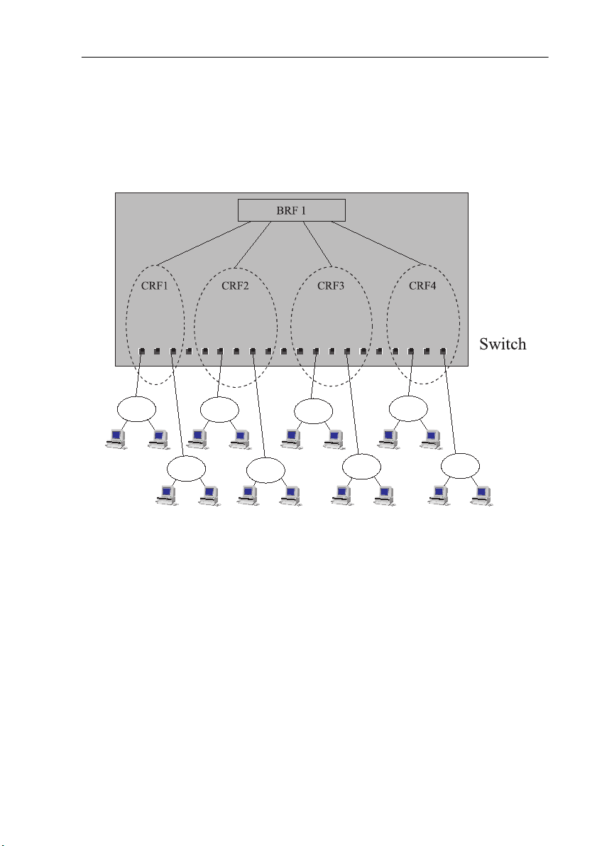
Figure 6. Typical Configuration with Switches Using Multi ple Bridging Modes
The switch bridging modes are founded on the concept of Logical Rings. This
Logical Ring concept is equivalent to the DTR (IEEE 802. 5r) standard’s
Concentrator Relay Function (CRF).
Each port on the switch belongs to a Logical Ring (CRF ), which is a logical
grouping of ports within the switch. A Logical Ring can consist of any number of
ports within a swit ch or a switch stack. The ports withi n a Logical Ring do not have
to be adja cent.
The Logical Rings are assi gned a ring number when the switch performs source
routing functions. The bridging is performed through the logical entity of the
Bridge Relay Function (BRF).
The Logical Ring (LR) communicates via a logical, virtual port with the Bridge
Relay Funct ion, which functions as a multi port (virtual) bridge between the Logical
Rings. The switch can support up to 63 logical rings.
CrossFire 8600/8605 Token-Ring Switches v. 1.2, P/N: 710001641 Switch Theory of Operation
Page 37

21
There are two levels of relay functions supported by the switch. The first level is
the TrCRF (Token Ring Concentrator Relay Function) to which the ports are
assigned. The secon d level i s th e TrBRF (To ken Ring Bri dge Rela y Functi on). This
is the parent r elay function to which TrCRF s ar e assigned. The switch mai ntains
certain configuration information and management statistics on a per BRF/CRF
basis. Therefore, when you access VLAN-specific switch configuration or
management screens (such as the
you will be prompted to specify the desired TrBRF for TrC RF.
Source Route Swi t chin g ( S RS)
This mode is used between ports comprising a Logi cal Ring.
SRS switching combi nes the normal transp arent bri dge funct ion with the abi lity to
forward frames based on source route information to locally a ttached source-route
bridges. The sw itch does not oth erwise act as a sourc e route bridge . For non sourcerouted packe ts, the s wit ch dec ision is ba sed up on dest in ation MAC Address es. For
source-rout ed packets, it is based on the source-route information com bined with
the destin ation MAC address.
The switch lear ns MAC addresses and source-routing route descriptors of Source
Route Bridges attached to local switch ports.
Parallel paths are eliminated via the IEEE 802. 1D Sp anning Tree Protocol.
Current Spanning Tree Information
screen),
Source Route Bridging (SRB)
The BRF acts as a multi port Source Route Bridge betwe en CRFs with the following
characteristics:
•
Each Logical Ring has a different ring number
•
Source Route Frames are forw arded between the Logical Rings by the Br idge
Relay Function based on the route information f ield
•
Non-source-route f r ames are not forwarded between logical rings
•
The Bridge Relay Function has a single bridge number and mult iple ring
numbers (one per Logical Ring)
SRS is used betwee n the ports of each logical ring. The Bridge Relay Functi on runs
the IBM Spanning T ree Protocol t o eliminate parallel paths with othe r source-route
bridges. T he IEEE 802.1D Spanning Tree Protoc ol is still used with each logical
ring. Duplicate MAC addresses are allowed
Rings.
Source Route Tra nsp aren t (SRT)
The BRF can combine transparent switc hing with Source Route Bridging. Non
source-rout ed packets are switched across logical rings by transpa rent bridging.
CrossF ire 8600/8605 Token-Ring Switches v. 1.2, P/N: 710001641 Switch Theory o f Operation
if they are on different Logical
only
Page 38

22
Source-routed frames are switched across logical rings by Source-Route Bridging
and within each logical ring by Source-Rou te Switching.
The Bridge Relay Function runs the IEEE 802.1D Spanning Tree Prot ocol.
Duplicate MAC addresses are
SRT/SRB
This is a specia l mode combi ning SRT a nd the SRB switc hing m odes. Ea ch Logic al
Ring will operate either in SRT mode or in SRB mode. Transparent bridgin g will
only take pl ace between logical rings in SRT mode. Sour ce-route bridg ing will take
place between all logical rings.
The purpose of the SRT/SRB mode i s to allo w duplicate MAC address es to be use d
when in SRT mode. The port s on which the dupli cate MAC addr esses reside c an be
reached only by source routing.
The Bridge Relay Fu nction runs the IBM Spanning Tree Protocol on the SRB
logical rings to eliminate paralle l paths with all source route bridges. It runs IEEE
802.1D Spannin g Tree Prot ocol on the SRT logica l rings to elim inate pa rallel paths
with other SRT bridges. The two resulting spanning trees are joined together.
The IEEE 802.1D Spanning Tree Protocol is still used to eliminate parallel pat hs
within each logical ring whether it is SRB or SRT.
The benefit of the SRT/SRB mode is that it all ows part of the network to be run in
SRT mode to accommoda te application s that do not support source routing, while
still supporting dupli ca te MAC addresses on a number of S RB ports (for example,
for SNA gateway applications).
allowed.
not
Filtering
Filtering is important for a LAN switch. Filters can be used to reduce broadcast
traffic, bloc k ce rtain protocols and provide security functions.
The switch provides filters for:
•
Destination or s ource MAC addresses
•
Destination service access point (DSAP)
•
Subnetwork Access Protocol (SNAP) type
Each protocol filter can be applied on a per-port basis for both input and output
traffic. This feat ure al lows certain protocols to be blocked from certain ports. For
example, filters can be established to allow only Systems Network Architecture
(SNA) traffic to f low to ports with SNA gateways.
Source and destinat ion MAC address filtering can be applied to all incoming
frames. The MAC address filters act in one of three ways:
CrossFire 8600/8605 Token-Ring Switches v. 1.2, P/N: 710001641 Switch Theory of Operation
Page 39

•
Block destination address at a specific port—this prevents the spe cified port
from sending frames to a specified destination.
•
Allow destination addres s at specific ports—this indicates that the specified
port must send frames to the specified destinations
•
Force destination address to a specific port—this allo ws forwarding to a
unicast address that has not been learned. It can also be used to limit the
forwarding of Multi cast addresses to a subset of ports. This last filter applies
to non-source-routing frames
only
.
only
.
Congestion Control
At regular intervals, the switch CPU inspect s the queues on all output ports. If a
queue size is above a cer tain threshold, the port is ins tructed to:
•
Set the transmit priority f or low priority frames to a spec ified high level
•
Delete old frames from the queue until it reaches a specified size
When the queue size agai n com es below a normal threshold size the port is
instructed to set the transmit priority back to the normal level.
Three Switching Modes
23
Cut-Through
In this mode the switch starts forwarding the packet to the output port as soon as
the destination address or the source-route of the incoming packet has been
resolved. Th is te chniqu e e nsures ve ry low la tency , t ypical ly in t he range of 30 -100
µs. However, if errors occur on the input port during the reception of a packet, the
error will still be forwarded to the output port . Note that cut-through can only be
used in transmis sions between ports which oper ate at 16 Mbps.
Store and Forward
In this mode, the switch receives the total packet from t he input port, checks it for
any errors and then st arts forwarding the packet to the destination port. This
technique wil l ensure that no faulty packet s ar e transmitted by output port. The
negative impact however, is higher latency, typically in the range of 40–2,000 µs
depending on the packet size. Though slower than cut-through mode, this is still
much faster tha t conventional bridges.
Auto (Adaptive C u t-T hrough)
This is a te chnique whereby t he swit ch will automati ca lly swa p betwe en stor e-andforward and cut-through modes based on an error threshold. If the number of
received faulty packets is low, then cut -through mode is used; if the number of
CrossF ire 8600/8605 Token-Ring Switches v. 1.2, P/N: 710001641 Switch Theory o f Operation
Page 40

24
faulty pack ets is hi gh, t he store a nd fo rward mode is use d. Th is pro vide s opt imiz ed
performance but introduces variable late ncy.
Token-Ring Port Operation Modes
Each Token-Ring port may operate in one of the following modes:
•
Half-duplex concentr ator port
The port be haves like an active MAU port for classical Token-Ring. Connects
to a single station in half-duplex mode. This is also known as Token Passing
(TKP) port mode.
•
Half-duplex station emulation
The port is conne ct ed to a por t on a MA U. Con nects to a class ical Token-Ring
segment with multiple stations. This is also known as Token Passing (TKP)
station mode.
•
Full-du plex concentrator port
Connects to a single station or to another switch in full-duple x mode. This is
also known as Transmit Immediate (TXI) port mode.
•
Full-duplex station emulation
Connects to another Token-Ring switch. This is also known as Transmit
Immediate (TXI) station mode.
•
RI/RO-like connection
The mode of operation can be configured manually or sensed auto ma tically with
the exception of RI/R O, when equipment i s connected to the port. The media spe ed
(4 or 16 Mbps) can also be manuall y configu red o r automa tica lly sens ed in al l por t
modes.
RI/RO-Like Connection
On CrossFire 8600, a RI/RO-like connection is available on fiber expansi on ports
and on ports 19 and 20. On CrossFir e 8605 , a R I/RO-l ike c onnect ion is p ossi ble on
all the 20 fiber ports and on fiber expansion ports.
This feature allows the switch to connect to CAU/LAM systems us ing the RI/RO
connections thus providing a RI/RO-like functionality. This enables the switch to
be eas ily insta lled in ex isting To k en-Ring netw or k s .
A loop-back function has been implemented on these ports so that if the port is
disabled or the swit ch is powe red off there will not be a break in the atta ched main
ring. This means that attaching a cable from the RI port of a MAU port to one of
the two switch port s in effe ct joins the primary and the backup r ing in a MAU/CAU
main ring system. Connecting the other end of the RI/RO conne ction to the other
switch port,
CrossFire 8600/8605 Token-Ring Switches v. 1.2, P/N: 710001641 Switch Theory of Operation
creates re dunda nt path s
because t he two swi tc h ports are c onn ected to
Page 41

25
the same segment.
enabled
there is a bre ak in the mai n ring, the ST P will place both ports in forward mode , and
all MACs on both segment s wil l be re learned.
If a swit ch p ort has been co nfigured to RI/RO mode, i t w ill automatically sense
whether the port has be en c onnected to RI or RO of the MAU.
➽ Note:
connected acc ording to the configuration. Any errors, such as attaching port 19 or
20 to a normal MAU port when the CrossFire 8600 port has been configured for
RI/RO, will cause a complete disruption of the ring to which the port is attached.
Theref ore, be careful when using the RI/RO feature.
, which will place one port in forward and the other in blocked mode. If
It is not possible to automatically verify whether an UTP/STP port has been
Therefore, the IEEE Spanning-Tree Protocol (STP) must be
Transmission Priority Queues
To address the needs of delay-sensit ive data, such as multime dia, the Token-Ring
ports of the switch have two transmit queues, a high-priority queue and a lowpriority queue.
The queue for a frame is determined by the value of the priority field in the frame
control (FC) byte. If FC priority is above a configura ble level (default 3), the frame
is put into the hi gh-priority queue. If an output port becomes congested, you can
dynamically configure the port to transmit all frames at high priority regardless of
the FC byte contents.
CrossLink Connections
Two switch stacks or switches may be interconnect ed by a number of parallel
Token-Ring con nec tions (up to 256 Mbps using eight por ts ). The traffic between
the switches will be shared between the connections.
Spanning Tree Protocol Support
IBM initi ally supported only Source Route Bridging (SRB) in its bridges, so most
networks were built to use it . T he main consideration for SRB implemen tations in
switches is the spa nning-tree algorithm for spanning tree explorers (STEs). IBM
originally implement ed a form of the Institute of Electrical and Electronics
Engineers (IEEE) spanning-tree algorithm. This algorithm, commonly referred to
as the IBM spanning tree, limits the STE frames to one copy per destination ring.
Some SRB implementations have also implemented the IEEE Spanning Tree
Protocol to be compatible with SRT br idges. The IEE E Spanning Tree Protocol is
not compati ble with the IBM Spanning Tree Protocol.
The switch suppo rts both the IEEE 802.1D and IBM Spanning Tree Protocols.
CrossF ire 8600/8605 Token-Ring Switches v. 1.2, P/N: 710001641 Switch Theory o f Operation
Page 42
26
VLAN Support
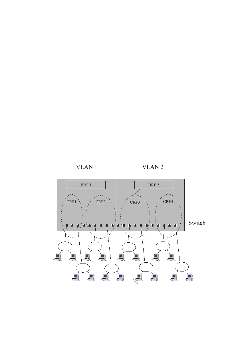
The vir tu al LAN (VLA N) c onc ep t c rea te s a vir t ual sw it ch wi thi n a ph y sica l s wi tch
or stack of switche s. A VLAN consists of CRFs and has its own Bridge Relay
Function atta ched. Frames are not forwarded across VLANs and ring numbers must
be unique within a VLAN.
•
A VLAN consists of a number of ports of a switch or stack of switches
•
No frames are forwarded betwee n ports belonging to dif ferent VLANs
•
Logical ring s on dif fer ent VLANs may be assig ned t he same ring num ber , b ut
ring numbers must be uni que within the same VLAN
•
For each VLAN, the stack can be assigned a separate IP address
•
The spanning tree pr otocol is execut ed independently within ea ch VLAN.
However, since al l B RFs use the same Bridge ID for th e s p an n i ng tr e e
algorithm, the spanning tree protocol will not function if ports from different
BRFs within one swi tch are connected.
A sample VLAN with a CrossFire 8600 or a Cross F ire 8605 is shown below.
Figure 7. A Switch Configured with Two VLANs
CrossFire 8600/8605 Token-Ring Switches v. 1.2, P/N: 710001641 Switch Theory of Operation
Page 43

27
Managem en t
SNMP
The switch can be managed via a SNMP manager. It supports ten Management
Information B as es (MIBs). Six of the MIBs are standard MIBs, whic h are defined
by RFCs and are include d with m ost SNMP managem ent app lic ation s. Four of the
MIBs are proprietary and are provided on the disk th at accompanies the switch.
SNMP management is supported via IP.
The following MIBs are supported:
Specification MIB
RFC1213 MIB II
RFC1493 Bridge MIB
RFC1525 SR Bridge MIB
RFC1573 Evolution of the Interfaces
Group of MIB-II
RFC1757/1513 RMON MIB/TR extensions -
Only partial support
RFC1749/1748 IEEE 802.5 MIB
DTR MIB IEEE 802.5r MIB
DTR MAC MIB IEEE 802.5r MIB
Olicom CrossFire 8600 switch series
Unit MIB
Olicom/Cisco VTP MIB
Table 7. Supported MIBs
Most user configurable variables will be supported in either the standard MIBs or
the proprieta ry MIB. Configuration sett ings, such as port attri butes, and operati onal
informatio n, s uch as address tables, are fully accessible through SNMP. Certain
other settings, such as passwords and console settings, cannot be viewed or
modified via SNMP for security reasons.
CrossF ire 8600/8605 Token-Ring Switches v. 1.2, P/N: 710001641 Switch Theory o f Operation
Page 44

28
Switch Manager for HP Ope nView for Wind ows
The Switch Manager is an applicatio n that runs under HP OpenVie w for Windows.
It provides an intuitive graphical user interface (GUI) that displays a chassis
physical view and supports configuration, performance monitoring, and
troubleshooting.
This applic ation is included with the switch.
For information abo ut S witch Manager on other platforms , please contact your
local Olicom sales representative.
Telnet Management and VT100 Management (Console)
The Console Management function may be a ccessed out-of-band via the TIA/EIA232-F (i.e. RS-232) port labelled MANAGEMENT or in-band via Telnet.
IBM LAN Network Manager
The switch does
support management by the IBM LAN Network Manager , but
not
it will allow L AN Network Manager LLC fra mes to flow thr ough the swit ch so tha t
communication to existin g LNM manageable h ubs and source route bridg es will be
maintaine d.
Some error reporting functions and ring map functions might be lost for the rings
attached t o through the switc h, because a Token-Ring Switch will not (and should
not) forward MAC frames, but only LLC frame s between ports.
RMON Support
RMON is an i ndustry -sta ndard m ethod for p rovid ing network stat isti cs monito ring
using SNMP. It al so col lect s faul t, pe rformance, and c onfi guratio n sta tist ics. It ca n
monitor continuously, even when communi cation with the management station is
not po ssible or e f f ic ient. RM ON can th en notif y the man ag ement s tation w h en an
exceptiona l condition occurs.
In typical SN MP manageme nt, the SNMP client has to continuous ly poll th e swi tch
for fault, performance, and c onfiguration information, waiting for the value to
change. This causes increased traffic thr ough the network. With RMON, you can
have the switch monitor a part icular statistic internally, and when the statistics
reaches a threshold, the switch will send a trap to the client. T h is monitoring
method reduces traffic between the SNMP client and the s witch.
The following groups defined in the RFC 1757 RMON MIB are supported in the
switch:
CrossFire 8600/8605 Token-Ring Switches v. 1.2, P/N: 710001641 Switch Theory of Operation
Page 45

•
The Statistics Group:
— The Token-Ri ng MAC-Layer Statistics Table.
— The Token-Ri ng Promiscuous Statistic s Table.
•
The History Group:
— The History Control Table.
— The Token-Ri ng MAC-Layer History Table.
— The Token-Ri ng P romiscuous History Table.
The following groups defined in the RFC 1513 Token-Ring Extensions MIB are
supported in the switch:
•
The Token-Ring Ring Station Group:
— RingStationControl Table does not support sets, only gets.
— Ring Station T able is not supported.
•
The Token-Ring Ring Station Order Group.
You can use an external RMON probe for full RMON support.
29
➽ Note:
➽ Note:
Reme mb er to enable
Access to RMON data is available only via an SNMP manageme nt
application that supports RFC 1757 and RF C 1513. You cannot access RMON via
the console interface of the switch.
RMON Statistics
on the
SNMP Configuration
menu.
Built-in Port Counters
The switch suppo rts a wide range of port counters, which enables you to obtain a
detailed overview of the po rt traffic. The co unters give a com p r ehensive overview
in the areas of:
•
MAC Layer Count ers
•
MAC Layer Error Counters
•
Frame Forwarding Counters
CrossF ire 8600/8605 Token-Ring Switches v. 1.2, P/N: 710001641 Switch Theory o f Operation
Page 46

30
Stackable Architecture
The CrossFire 8600 and the CrossFire 8605 switch can be stacked using the
CrossFire 863 0 Stacker Link module, the CrossFire 8635 Internal Stacker mo dule
or the CrossFir e 8300 Switch Stacker for conne cting up to eight switc hes in a stack.
Back-to-Back
Two CrossFire 8600 series switches can be connected together by fitting each
switch with the CrossFire 8630 Stacker Link module and connecting the switches
together using an appropriate stacker link cable. This simple connection doubles
the number of ports available, giving a total maximum of 56 ports.
Internal Stacker
The CrossFire 8635 Internal Stacker Module can be inserted into the stacker port of
a switch. It allows up to four additional switches from the CrossFire 8600 series to be
stacked together with the switch containing the CrossFire 8635. Each switch in the
stack must be equipped with a CrossFire 8630 Stacker Link module and an
appropriate stacker link cable. This can result in a stack of as many as five CrossFire
8600 series switches, supplying a total of up to 140 switched Token-Ring ports. The
CrossFire 8635 Internal Stacker Module works as a common backplane switching
fabr ic, which provides 1. 4 Gbps of aggregate bandwidt h.
External Stacker
The CrossFir e 8300 Swit ch Stack er is an exte rnal s tack uni t that a llo ws up to eig ht
CrossFire 8600 series switches to be stacked together. Each switch in the stack
must be equipped wi th a n CrossF ire 8 63 0 Stacker L ink Mod ule and an a ppropria te
stacker link cable. Thi s can resu lt in a to tal of up to 224 swi tched Token-R ing ports.
The CrossFire 8300 Switch Stacker works as a common backplane switching
fabric, which provides 2.2 Gbps of aggregate bandwidth.
➽ Note:
The CrossFire 8600 and the CrossFire 8605 can be stacked together with
switc h es f r om th e Cr o s sFire 8600 ser i es in any desired co m b in a ti o n. All switc h es
in a stack m u st , however, run th e same softwar e ver sio n .
Optional Redundant Power Supply
The switch has an input for a backup power supply. It is compatible with the
CrossFire 8 310 Redundant Power Supply Chassis, whic h can suppl y backup power
for up to six switches, when up to six CrossFire 8311 Redundant Power Supply
Units are installed in the chassis. This gives a high degree of resilience to power
supply fail ures . The s wit ch wil l start usi ng the e xternal p ower s upply i f t he intern al
supply fails. The sw itch monitors the power source and informs the network
management sys tem which supply is in use.
CrossFire 8600/8605 Token-Ring Switches v. 1.2, P/N: 710001641 Switch Theory of Operation
Page 47

31
The CrossFir e 8300 S witch Stacker also ac commodates an optional switch matrix
8301, which incl udes a redunda nt power supply, ensuring the highest degree of
resilience in the stack of switch es.
➽ Caution:
The redundant power s upply unit CrossFire 8311 is
Both the CrossF ire 8311 unit and the switch
disconnecting the DC power cable.
must be off
hot-swappable.
not
before connecting or
CrossF ire 8600/8605 Token-Ring Switches v. 1.2, P/N: 710001641 Switch Theory o f Operation
Page 48

32
Benefi t s of the Cr os sF ir e 8 60 0 an d th e C r o ss Fir e 86 05
This section looks into the benefits that can be derived f rom t he technical featur es
of the switch.
Token-Ring Port Operation Modes
Each port can be independently configured to one of the following operating
modes:
Feature Function Benefit
Half-duplex
concentrator port
Half-duplex station
emulation
Full-duplex
concentrator port
Full-duplex station
emulation
RI/RO-like
connection
(
Cros sFire 8600
on
ports 19 and 20,
Cros sFire 8605
on
all 20 fiber ports)
Port behaves like an
active MAU port fo r
classical Token-Ring.
The port is
connected to a port
on a MAU.
Connects to a single
station in full-duplex.
Connects to another
switch in full-duplex
mode.
Allows connection
of the RI /RO p or t
from a MAU or CA U
directly to the
switch.
Connects to a single station in
half-duplex m ode. Compat ible
with ol d er ad ap t er s .
Connects to classical TokenRing segments with multiple
stations in existing
installations.
Allows high-performance
station and server connection
and allows high performance
server attachments with up to
97% improvement over a halfduplex Token-Ring
connection.
Allows easy connection
between switches.
Enables easy integration into
existi n g in s t allatio n s.
Table 8. T oken-Ring Port Opera ti on Mode s
CrossFire 8600/8605 Token-Ring Switches v. 1.2, P/N: 710001641 Switch Theory of Operation
Page 49

Feature Function Benefit
33
Auto matic port
sensing of operating
mode
Auto mati c media
speed detection
(4 or 16 Mbps)
The port senses
automatically which
mode to operate in.
Enables the swit ch to
detect automatically
the speed of
indivi dual ports.
Congestion control
The size of each
port’s output queue
is monitored. I n cas e
of congestion the
queue size is
adjusted through
frame priority
adjustment and
frame purging.
Table 8. Token-Ring Port Operation Modes
Makes installation easier and
faster.
Makes installation easier and
faster.
Minimi ze s the eff ec t o f
congestion on output ports
CrossF ire 8600/8605 Token-Ring Switches v. 1.2, P/N: 710001641 Switch Theory o f Operation
Page 50

34
Three Swi tch in g M odes
Feature Function Benefit
Cut-Through
Switch es with
minimum and
constant latency,
approximately 35 µs
Store and F orward
Each packet is
forwarded only after
the entir e pac ket has
been rece ived by th e
switch . This is used
for data transfer
betw een LAN
segments of different
speeds or for LAN
segments with a high
error rate.
Auto
(Adaptive
Cut-Through)
Cut-through
switching that checks
for error packets. If a
port’s errors exceed a
user-defined threshold
then the port switches
to store and forward.
T able 9. Switching Modes
Lowest possible switch-latency,
which means optimal res pons e
time for end-users.
Does not propagate err ors to
other segments.
Same speed as cut-through
switching, but with built-in
adaptation to errors whic h
means that bandwidth is
effectively preserved
CrossFire 8600/8605 Token-Ring Switches v. 1.2, P/N: 710001641 Switch Theory of Operation
Page 51

Expansion Module Slots
Feature Function Benefit
35
Four-port RJ-45
UTP/STP
Four-port fiber
(ST)
ATM155 uplink
High-Speed TokenRing (HSTR)
Gives the switch an
additional 4 or 8
Token-Ring UTP/
STP ports.
Gives the switch an
additional 4 or 8
Token-Ring Fiber
ports.
Gives the switch
access to 1 or 2
ATM155 uplink
connection(s) with
LAN Emulation.
Gives the switch
additional 2 or 4
HSTR ports.
Enables gradual expansion of
switch capacity.
Enables i nsta llati on i n e xist ing
fiber RI/RO connections and
fiber cab lin g en vi ronmen ts (up
to 2 km) .
Enables smooth migration to
ATM backbone networks and
enables redunda nt ATM
uplinks to be established.
Allows VLANs to be
multiplexed between switc hes
using ATM.
HSTR allows Token-R i ng
operation at 100 Mbps an d
offers thus a 625 %
perfo rm an c e im pr ov ement
over “cla s sic” 16 Mbps
Token-Ring.
HSTR is by far the most costeffective and non-disruptive
method for performance
upgrade of one existing
Token-Ri ng LAN.
Table 10. Expansion Module Slots
CrossF ire 8600/8605 Token-Ring Switches v. 1.2, P/N: 710001641 Switch Theory o f Operation
Page 52

36
Multiple Bridging Modes
Feature Function Benefit
Transparent
and Source Route
Switching (SRS)
Source Route
Bridging (SRB)
Source Route
Transparent
Bridging (SRT)
Switching is based on
MAC addresses only.
Learns MAC
addresses and source
routing rout e
descriptors of Source
Route Bridges
attach e d to lo cal
switch ports.
The switch ports may
be grouped into logical
rings. The switch acts
as a standar d
multipor t S our ce
Route Bridge between
logical rings. Non
Source Route frames
(NSR) are not
forwarded outside the
logical ring.
NSR frames are
forwarded between
Logical Rings based
on MAC ad dr ess.
Source Route frames
are forwarded as by
SRB.
Allows ea s y in s ta llation in
environm ents with no need for
Source Route Bridging.
Allows ea s y in s ta llation in
existing Token-Ring networks
where Source Route Bridges a re
used. Allows easy replacement
of bridges with switches.
Allows the mix of source route
and non source route protocols
in the network.
SRT/SRB
Combi n es the SRT
and SRB modes.
Allows the use of duplicate
MAC addresses when running in
SRT. Ports with duplicate MAC
addresses are reac hable onl y via
source routing. Duplicate MAC
addresses are typi cally found in
installations utilizing SNA
gateways and/or front-ends.
Table 11. Multiple Bridging Modes
CrossFire 8600/8605 Token-Ring Switches v. 1.2, P/N: 710001641 Switch Theory of Operation
Page 53

Spanning Tree Protocol
Feature Function Benefit
37
IEEE 802.1D
Allows redundant
network paths to be
defined in both S RB
and transparent
switching
configurations.
IBM
When in SRB/SRT
mode, a com bination
of IBM spanning tree
and IEEE 802.1D is
used.
Table 12. Spanning Tree Protocol
No single point of failure. The
duplicate STP modes allo w
operation in both transparent
and source route bridging
modes
Same as abo v e, a nd in addi ti on
ensures compatibility in IBM
SRB installations.
CrossF ire 8600/8605 Token-Ring Switches v. 1.2, P/N: 710001641 Switch Theory o f Operation
Page 54

38
Management
Feature Function Benefit
SNMP
VLAN support
HP OpenView for
Windows
Additional Network
Management
applications available
for Unix platforms:
HP OpenView NNM
for HP- UX
and
Tiv oli TME 10
NetV ie w for AIX
Telnet management
Can be configured
and managed using
SNMP management
station.
Ensures the
avai la bilit y of a high
number o f switched,
port based, VLANs
for an enterprise
network.
Full Graphical HP
OpenView for
Windows
management
application.
Allows management
from a any LAN
station via Telnet.
Allows integration into any
SNMP-based management
environment.
Eases network-wide
administration by enabling
ports to be grouped togeth er in
a logical w ay. Provides
performance and security
control. Enables effective
broadcast control.
Allows full graphical
integration into HP OpenView
management environments.
Makes management flexible by
enabling manageme nt from
any statio n.
VT100
management
Allows out-of-band
management f rom an
Enables management of
switches in remote locations.
external VT100 type
terminal connected
directly or via a
modem.
T able 13. Management
CrossFire 8600/8605 Token-Ring Switches v. 1.2, P/N: 710001641 Switch Theory of Operation
Page 55

Network Monitoring
Feature Function Benefit
39
RMON support
Passive Port
Monitoring
Active Port
Monitoring
Built -i n po rt
counters
Support for TokenRing specif i c remo te
monitoring.
All traf fic flowi ng on
the monitore d p ort is
copied to th e
monitoring port (the
monitoring port is a
true copy of the
monitored port).
All traffic swit ch e d
to and from the
monitored port is
also sent to the
monitoring port (the
order and timing of
frames on the
monitoring port can
be differ ent).
Many MAC layer,
error, and frame
forwarding counters
are collected per p ort
Enable s collection and analysis
of enha nc ed trafficmanagement data.
Eases the man agement task by
making it easy to collect
Token-Ri ng s ta tistic s with a
special passive network
analyzer.
Eases the man agement task by
making it easy to collect
network st atisti cs and car ry out
protocol analysis. Active
monitoring respects the MAC
protocol, allowing the use of a
standard network analyzer.
Provides a detailed picture of
port traffic.
Table 14. Network Monitoring
CrossF ire 8600/8605 Token-Ring Switches v. 1.2, P/N: 710001641 Switch Theory o f Operation
Page 56

40
Filtering
Feature Function Benefit
MAC address
Logical Link
Control (LLC):
DSAP/SNAP
Table 15. Filtering
Allows filtering
base d o n f r a m e
source and
dest in a t i o n MAC
addresses.
Allows filtering
base d o n L LC
parameters DSAP
(Destination Source
Acces s P o int) and
SNAP (Subnetwork
Access Protocol).
Preserves available network
bandwidth by re stricting traf fic
from propagating beyond the
need ed li m i ts. Enable s
enhanced network security
policies to be es tablished.
Same as above.
CrossFire 8600/8605 Token-Ring Switches v. 1.2, P/N: 710001641 Switch Theory of Operation
Page 57

Connectivity Opti ons
Feature Function Benefit
41
CrossLink highspeed in t e r-s w itch
connection (
up to
256 Mbps using
eight ports)
Stackable:
3 possibilities:
A. 2 switch stack
B. 5 switch stack
C. 8 switch stack
Optional
redundant power
supply
Allows CrossFire
T oken-Ring switches
to be interconnecte d
using 1-8 switch
ports.
Stack Products
Needing:
A. 2 x 8630
B. 1 x 8635 and
4 x 8630
C. 1 x 8300 and
8 x 8630
Up to six switches
can receive backup
power from one
CrossFire 8310
Redundant Po wer
supply, fully
equipped with six
CrossFire 8311
power supply units.
(Note that CrossFire
8311 is
not
hot-
swappable.)
Provides easy an d scalable
switch inter connection.
Allows several switches to be
stacked, ac commodating
switch scalability up to 224
switched Token-Ring ports.
Gives a high degree of
resilience to power supply
failures when used in critical
applications.
T able 16. Connectivity Options
❏
CrossF ire 8600/8605 Token-Ring Switches v. 1.2, P/N: 710001641 Switch Theory o f Operation
Page 58

42
CrossFire 8600/8605 Token-Ring Switches v. 1.2, P/N: 710001641 Switch Theory of Operation
Page 59

3. Preparing for Instal lation
Before installing the CrossFire 8600 Token-Ring Switch or the CrossFire 8605
Token-Ring Fiber Switch, read this chapter carefully.
The following topics are dis cussed in this chapter:
•
“Safety Recommendat ions”, starting on this pa ge.
•
“Site Requirem ents”, starting on page 46.
•
“Unpacking and Ins pecting” starting on page 48.
Safety Recommendations
Follow these gui delines to ensure general safety during and after the inst allation:
•
Keep the chassis area cl ea r and dus t-free during and after installa tion.
•
Keep tools away from walk areas where you and others could trip over them.
•
Do not wear loo se c lot hin g that c ould ge t c aught in the c hass is. F asten your tie
or scarf and roll up your sleeves.
•
Wear safety glasses when working under any conditions that might be
hazardous to your eyes.
43
•
Do not perform any action that creates a potential hazard to people or makes
the equipment unsafe.
Safety with Electricity
Follow these gui delines when working on equipment powere d by ele ctricity.
➽ Danger:
➽ Danger:
wired and ear thed receptacle. Any equipment to whic h the switch will be attached
must also be connected to properly wired and earthe d receptacles.
➽ Warning:
jewelry (i ncludin g ri ngs, neckl aces, br acel ets and wa tche s). Metal obj ects wi ll heat
up when connected to power and ground and can cause serio us burns or weld the
metal object to th e te r m i n als.
CrossF ire 8600/8605 Token-Ring Switches v. 1.2, P/N: 710001641 Prep aring for Installat i on
Do not open the switch. Dangerous voltages inside.
To avoid shock hazard the power cord must be connected to a properly
Before working on equipment that is connected to power lines, re mo ve
Page 60

44
➽ Warning:
periods of lightning activi ty. Read the installation instructions before you connect
the system to its power source.
To turn power
ON/OFF switch. Note that if the switch is connected to an ext ernal Redundant
Power Supply Unit (RPSU), the power cord must be removed from both units.
•
•
•
•
•
•
Do not work on the system or connect or disconnect cables during
the switch, you must disconnect the power cord; there is no
off
Locate the emergency power -off switch for the roo m in whic h you are
working. Then, if an elec trica l acciden t occurs, you can act quic kl y to turn off
the power.
Before worki ng on t he s ystem, un plug t he po we r cord. To avoid t he possib ili ty
of elect rical shoc k, u nplu g t he po wer cord from t he out let be fore de tach ing the
power cord from the switch.
Disconnect all power before doing the following:
— Installing or removing a chassis
— Working near power supplies
— Performing a hardware upgrade
Do not work alone if potentially hazardous conditions exist.
Never assume that power is disconnected from a circuit. Always check.
Look carefully for possi ble hazards in your work area, such as moist floors,
ungrounded power extension cabl es, and missing safety grounds .
•
If an electrical accident occurs, proceed as follows:
— Use caution; do not become a victim yoursel f .
— Unplug the power cord(s).
— If possible, send another person to get medical aid. Otherwise, assess the
condition of the victim and then call for help.
— Determine if the person needs rescue breathing or external cardiac
compressions; then take appropriate action.
CrossFire 8600/8605 Token-Ring Switches v. 1.2, P/N: 710001641 Preparing for Installation
Page 61

45
Preventing Electrostatic Discharge Damage
Electrostatic discharge (ESD) can dama ge eq uipment and impair electri cal
circuitry. I t occ urs when electronic components are improperly handled and can
result in complete or intermittent failures. Always follow ESD-prevention
procedures when removing and replacing components. Ensure that the chassi s is
electrical ly connecte d to earth ground using an ESD mat or a ground wire. Wear an
ESD-preventive wrist strap, ensuring that it makes good skin contact. To safely
channel unwante d ESD vol tages to gro und, connec t the cl ip to an u npainted s urface
of the chassis frame. To properly guard against ESD damage and shocks, the wrist
strap and cord must operate effectively. If no wrist strap is available, ground
yourself by touc hing the metal part of the chassi s.
➽ Caution:
For safety, periodically check the resistance value of the antistatic strap,
which should be between 1 and 10 MΩ.
CrossF ire 8600/8605 Token-Ring Switches v. 1.2, P/N: 710001641 Prep aring for Installat i on
Page 62

46
Site Requirements
Following are the site requirements for installation.
Environment
Choose a clean, dust-fre e, (preferably) air-conditioned location. Avoid direct
sunlight, heat sources, or areas with high levels of EMI (Electromagnetic
Interference).
Chassis Accessibility
Make sure the front and back pan el of the equipment is accessib le so that you can
monitor the LED indic ators and access the control switches. Leaving enough
clearance at the front and back will also allow easier cabling and service.
Cooling and Airflow
Two fans, which are located at the left side of the switch, cool the interior by
drawing air through vents on the left side and forcing heated air out through holes
in the right side. If the internal temperature exceeds 50°C (112°F), a te mperature
error is reported to the console.
➽ Caution:
that exc eeds t he maximum re commended ambient temperature of 40° C (104°F). T o
prevent airf low rest ric tion, you must allow at least 7.6 cm (3") of clear ance around
chassis openings for proper airflow.
To protect the equipment from overheating, do not operate it in an area
Power
The source e lectric al outle t should b e insta lled nea r the swi tch, be easily accessible ,
and be properly grounded.
Also, observe the following power cable considerations before you begin
installation of the CrossFire 8600 Token-Ring Switch and/or the CrossFire 8605
Token-Ring Fiber Switch.
1. The socket outlet shall be installed near the equipment and sh all be easily
accessible.
2. T o pre ve nt elect rical shock, the po wer cord set used mu st compl y with nationa l
regula tions .
2a. The female receptacle of the cord must meet CEE-22 requirements.
CrossFire 8600/8605 Token-Ring Switches v. 1.2, P/N: 710001641 Preparing for Installation
Page 63

47
2b. The cord must be UL listed, CSA label led, and consist of three cond uctors
with a maximum of 15 feet in length. T ype SVT or SJT cord sets shall be
used for units which stand on a desk or table. Type SJT cord sets shall be
used for units which stand on floor.
2c. The male plug for units operating at 115 VAC shall consist of a par allel
blade, grounding type attachment plug rated 15 A, 125 VAC.
The male plug for units operating at 230 VAC shall consist of a tandem
blade, grounding type attachment plug rated 15 A, 250 VAC.
The male plug fo r units operati ng at 230 VA C (outs ide of the Unite d Sta tes
and Canada) shall consist of a grounding type at tachment plug rated 15 A,
250 VAC a nd hav e the a ppropriate safety approv als for the count ry in which
the equipment will be installed.
➽ Caution:
Support the CrossFire 8600 Token-Ring Switch and/or the CrossFire
8605 Token-Ring Fiber Switch while you are installing the unit to avoid dropping
it on the floor or any equipment beneath it in the rack. The CrossFire 8600 TokenRing Switch unit and the CrossFire 8605 Token-Ring Fiber Switch unit each
weighs approxima tely 8.8 kg (19.4 lbs).
➽ Caution:
To separate the switch from the power, pull the power cord completely
out from th e s o ck et . Th e p ower s oc ke t mu st be easily accessible an d lo ca te d n ea r
the unit.
➽ Warning:
All RJ-45 c onnectors m ust only b e connected to safe ty extra low voltage
(SELV) circuits like local area networking (LAN).
➽ Warning:
This product relies on the building’s installation for short-circuit
(overcurrent) protection. Ensure that a fuse or circuit breaker no larger than
120 V AC, 15A U.S. (240 VAC, 10A international) is use d on the phase conductors
(all current-carrying conductors).
➽ Warning:
A voltage mismatch can cause equipment damage and may pose a fire
hazard. If the voltage indicated on the label is different from the power outlet
voltage,
➽ Caution
this unit is
be off
do not connect the chassis to that r eceptacle
: If you ar e using the redundant power supply uni t CrossF ire 8311 not e that
hot-swappable . Both the CrossFire 8311 uni t and the switch
not
before connecting or disconnecting the DC power cable.
.
must
CrossF ire 8600/8605 Token-Ring Switches v. 1.2, P/N: 710001641 Prep aring for Installat i on
Page 64

48
Unpacking and I n specting
Immediately after receiving the equipment, examine all shipping containers and
contents for damage. If any damage has occurred, noti fy the shipping carrier.
Unpack the unit by removing the packing material and lifting it from its protective
enclosures. Visu ally examine the equipme n t and check the co ntainer for related
parts and accessories. You should have the followi ng items:
•
One CrossFire 8600 Token-Ring Switch
OR
One CrossFire 8605 Token-Ring Fiber Switch
•
One
CrossFire 8600/8605 Token-Ring Switches Guide to Operations
(this guide)
•
One OC-8830 Token-Ring Switch Program Disk Set
•
One OC-8840 Token-Ring Swit ch Man age r for HP OpenView for Windows
(also works as sta nd-alone without HP Open View under Windows).
•
One
CrossFire 8600 Series Token-Ring Switch Manager
for HP OpenView for Windows Guides to Operations
•
One serial cable for the management port
•
One plastic bag containing four adhesive rubber feet and rack mounting
screws, Allen key, nuts and washers.
Report any missing part s and any damage not relate d to shippi ng to your cus tomer
service representative.
➽ Note:
CrossFire 8600/8605 Token-Ring Switches v. 1.2, P/N: 710001641 Preparing for Installation
Keep the packing materials for future use.
warranty should be shipped in their original packin g materials.
If you have received your equipment before your site is fully prepare d, after
inspection, you should keep all of the components in the original shipping
containers and store them in a physically and environmentally safe place.
When you are ready to begin the installation, please refer to the next chapter,
Chapter 4, “Installation”, for important instructions and directions.
All components returned under
Page 65

Rules to Remember
This section wil l help you unde rstand the physical con figurat ion restrict ions for the
switch. In brief, you must remember the following rules when planning to install
the swi tc h :
•
18,192 byte maximu m phy sical frame length.
•
For s h ared-med ia LAN se g ments, acceptable distances are defined by the hu b
or concentrator attached to the switch port.
•
Straight-through cables for all ports.
•
If you create parallel pat hs direc tly between switches, be sure that you have
enabled the spanning tree protcol (see “Spanning Tree for TrBRF Screen” on
page 99). The default setting for the spanning tree pro tocol is disabled.
•
The spanning tree protocol will not function between different BRFs within
one switch.
The following paragraphs provide greater detail about the physical restrictions.
Frame Length Li mit
The switch suppo rts a maximum physical frame length of 18, 192 bytes. This
corresponds to a Maximum Transfer Unit (MTU) of 17,800 byte s. The default
maximum physical fra me len gth of the switc h is 4,546 bytes which corr espond s to
an MTU of 4,472 bytes.
49
Please read sect ion “Required Network Preparation - F ram e Length Limit” on
page 55 before you start the installation. This section contains more detailed
information on the frame length limits.
Cables and Distances between Devices
The
CrossFire 8600
(UTP or STP), and 150 ohm STP, as defined in the EIA/TIA 568A and ISO/IEC
11801:1995.
On
CrossFire 8605
8610 Token-Ring UEM.
The
CrossFire 8605
VF-45 connector. Fib er cable lenghts up to 2000 meters are supported.
See Appendix B, “Cable and Pin Information” for specif ic information on
supported ca ble types, cable lengths and connector pinouts .
CrossF ire 8600/8605 Token-Ring Switches v. 1.2, P/N: 710001641 Prep aring for Installat i on
supports attachment to 100 ohm and 120 ohm twisted-pair
, a UTP/STP connection is only supported via the CrossFire
supports 50/125 µm and 62.5/125 µm fiber cables with a
Page 66
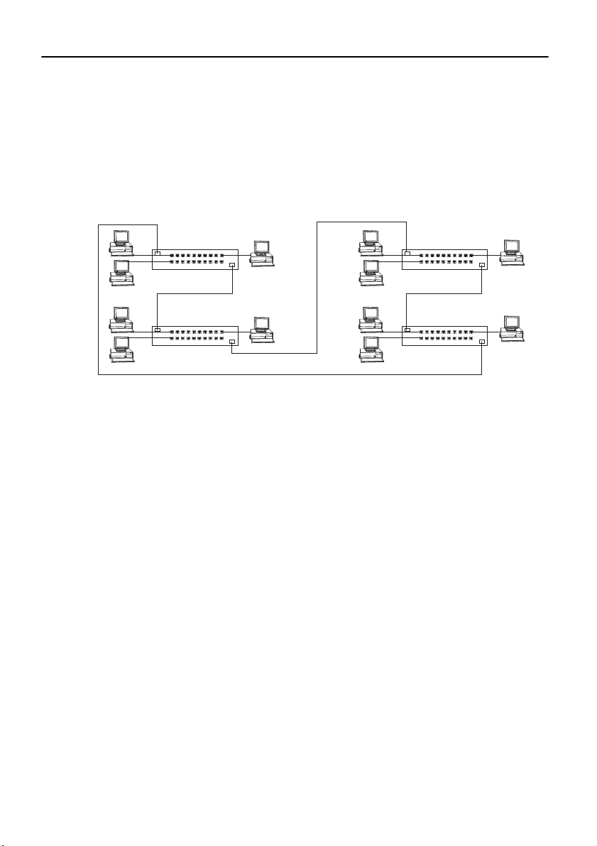
50
Sample Applications for the CrossFire 8600 and the CrossFire 8605
The CrossFire 8600 and /or the CrossFire 8605 switch allows you to make
incremental changes in your network to address bot h immediate and long-range
performance chall enges. For ex ample, a T oken-Rin g LAN o f 80 st ations i ncl uding
4 server s might exper ience per f o rmance pr o b l ems as a result of increa sed traffic.
As it is currently structured, the LAN looks like the one in Figure 8.
MAU
19 Workstations
MAU MAU
19 Workstations
Figure 8. Typical LAN Segmentation
Server
Server
MAU
19 Workstations
19 Workstations
Server
Server
All of t he s tation s are at tache d to a cces s unit s lo cate d i n a s ingle wi ring clos et. You
can instal l an swi tc h in th e same wirin g clo set a nd divide the LAN into 4 s egme nts
of 20 stations each. One acces s-uni t port from each segmen t wil l be conne cted t o a
port on the switch via a patch cable. Final ly, the four servers are removed from the
access units to which they have bee n attached and their cables moved to four ports
on the switch (as depicted in Figure 9).
Each group of 19 user s att ached to an acce ss unit no w shar es a ded icate d, 16 Mbps
path to the serve r. Each server ha s a dedicate d, 16 Mbps path upon which to serv ice
requests. The overall capacity of this solution is 64 Mbps; network capacity has
increased fourfold.
CrossFire 8600/8605 Token-Ring Switches v. 1.2, P/N: 710001641 Preparing for Installation
Page 67
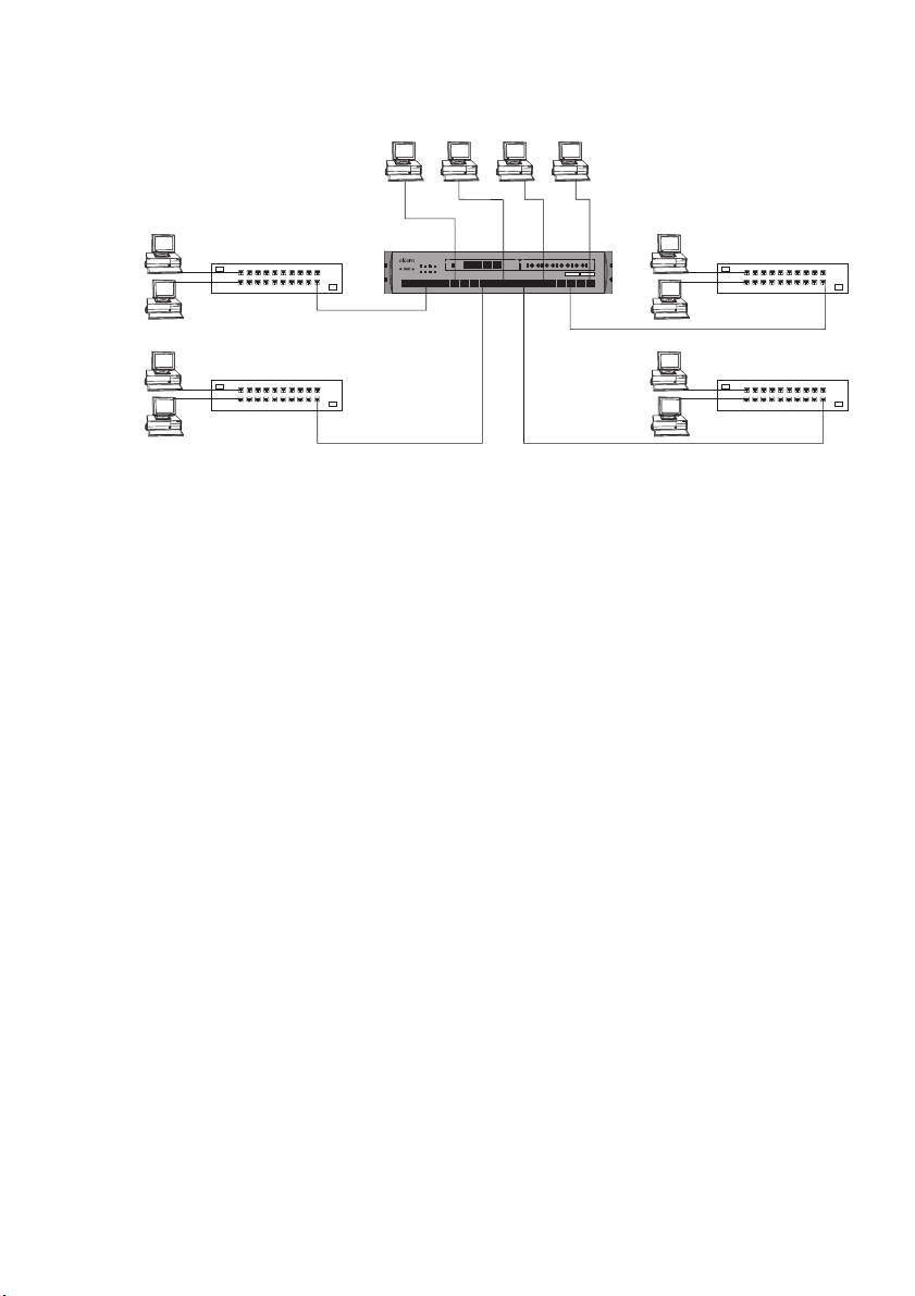
Servers
51
MAU
CrossFire 8600
STACK-LINK
OK
ERR
1
234
ATTACH
RXTX
DIAGPWR RSTERRMANAGEMENT
876109
3254
1
CrossFire
ERR
1
151211 1413 17161918 20
TXTX RX TXRX
2
TOKEN-RINGSWITCH OC-8600
INSINSINSOK
RX TX RX INS
3
4
ACTACTACTACT
MAU
19 Workstations 19 Workstations
MAU MAU
19 Workstations
19 Workstations
Figure 9. A Simple Application of the Switch
Some large, mult is egment, hierarchical Token-Ring networks experience
congestion at the campus backbone level. Although this congestion can oft en be
relieved by converting the backbon e to a higher s peed, share d-media protoc ol or by
install ing additional bridges or dual backbones to eliminate bottlenecks , the
CrossFire 8600 switch an d/or the CrossFire 860 5 switch o ffer dedicate d-media that
might be longer lived or more economical if you eventually need higher demand
applications.
Figure 10 o n the ne xt pag e i llus trate s a typic a l network wit hout the Cro ssFi re 8600
or the CrossFire 8605 switch. This network is a three-level, hierarchical, campu s
network. Figure 11 and Figure 12 offer several alternatives for using
the CrossFir e 8600 or the CrossFire 8605 switch.
CrossF ire 8600/8605 Token-Ring Switches v. 1.2, P/N: 710001641 Prep aring for Installat i on
Page 68
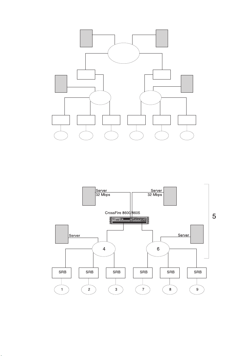
52
Server
Server
5
SRB SRB
SRB
Server
SRB
8
9
Server
4 6
SRB
1
SRB
SRB
2
3
SRB
7
Figure 10. Typical Network without the CrossFire Switches
In Figure 11, the congest ed campus backbone and the source-routing bridges
(SRBs) attached to it ha ve been replaced by an CrossFire 8600 or a CrossFire 8605.
Figure 11. Relieving the Overstressed Backbone
CrossFire 8600/8605 Token-Ring Switches v. 1.2, P/N: 710001641 Preparing for Installation
Page 69
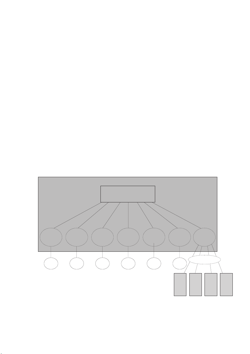
53
The Next Step
Typically, the first point of congestion in this newly configured network would be
the server s. Because the usual m ode of operation for a To ken-Ring adapter is halfduplex, the servers can either send or receive information with one other segment
attached t o the swit ch. I f t he server adapt ers are re plac ed wit h f ull-dupl ex adapt ers,
such as the Olicom OC-3118 or the Olicom OC-3137, and are attached as singlestation segments as shown in Figure 11, they can send and receive data
simultaneo usly. The capacity of each server is now 32 Mbps per port.
However, network congestion is not always at the ba ckbone level. In Figure 12, the
two MAUs and six bridges have been replaced by a single switch. Internally, the
switch is c onfi gured wi th one BRF a nd se ven CRFs , allowi ng t he s witch t o re place
the MAUs and bridges without the need for further reconfigurat ion. This
configuration greatly improves performance by allowing switching directly from
ring to ring. The four serve rs, each with a full-duplex con nection to the switch, have
been grouped in CRF 5.
If even better perf ormance is needed, the switch s hown in Figure 12 can be replaced
with a stack of s witche s. A stack c an pro vide up to 22 4 port s, maki ng it fea sable to
connect workstations directly to a switc h port. A direct connection prov ides a
dedicated 32 Mbps for users with high bandwidth requirements.
Switch
BRF
CRF 1
1 2
CRF 2
CRF 3
3
CRF 7
7
CRF 8
8
CRF 9
9
Server
Server Server Server
CRF 5
32 Mbps
Figure 12. Replacing SRBs with CrossFire 8600 or CrossFire 8605
CrossF ire 8600/8605 Token-Ring Switches v. 1.2, P/N: 710001641 Prep aring for Installat i on
Page 70
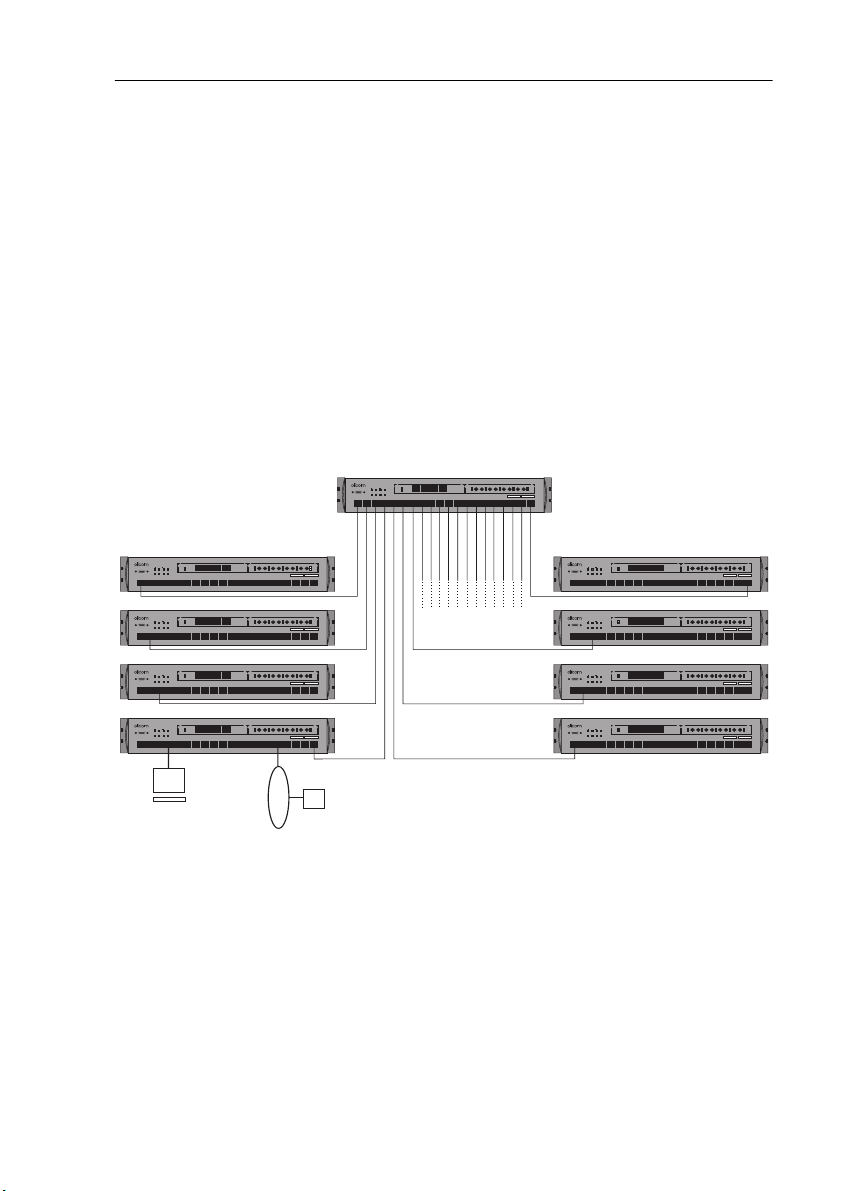
54
Important Management Considerations
A star-wired topology (see Figure 13) helps determi ne problems in a network
because no single cable carries all of the traffic on the network. However, serial
connections could reduce network reliability since each connect ing cable and
switch could potentially divide the net work should a failure occur.
If you create parallel paths directly betwee n switches, be sure you have enabled
spanning tree protocol (the default setting for spanning tree protocol is no or
disabled). Parallel paths cr eate endless loops that cause unsatisfactory network
operation unless you configure the switch for spanning tree capability. The
spanning tree algorithm disconnects loops in networks using the transparent
bridging algorithm or the SRT algorithm, and will block a port of one of the
switches in the parallel paths . If the port in the primary path fails, the port that has
been blocked will change automatically to the forwarding stat e, keeping the
network operational.
CrossFire
TOKEN-RINGSWITCH OC-8600
RX TX RX INS
INSINSINSOK
STACK-LINK
OK
ERR
1
234
ATTACH
RXTX
DIAGPWR RSTERRMANAGEMENT
876109
3254
1
ERR
1
151211 1413 17161918 20
TXTX RX TXRX
ACTACTACTACT
4
3
2
CrossFire
TOKEN-RINGSWITCH OC-8600
INSINSINSOK
RX TX RX INS
STACK-LINK
OK
ERR
1
234
ATTACH
RXTX
DIAGPWR RSTERRMANAGEMENT
876109
3254
1
STACK-LINK
OK
ERR
1
234
ATTACH
RXTX
DIAGPWR RSTERRMANAGEMENT
876109
3254
1
STACK-LINK
OK
ERR
1
234
ATTACH
RXTX
DIAGPWR RSTERRMANAGEMENT
876109
3254
1
STACK-LINK
OK
ERR
1
234
ATTACH
RXTX
DIAGPWR RSTERRMANAGEMENT
876109
3254
1
ERR
1
151211 1413 17161918 20
CrossFire
ERR
1
151211 1413 17161918 20
CrossFire
ERR
1
151211 1413 17161918 20
CrossFire
ERR
1
151211 1413 17161918 20
TXTX RX TXRX
2
TXTX RX TXRX
2
TXTX RX TXRX
2
TXTX RX TXRX
2
4
3
TOKEN-RINGSWITCH OC-8600
RX TX RX INS
INSINSINSOK
4
3
TOKEN-RINGSWITCH OC-8600
RX TX RX INS
INSINSINSOK
4
3
TOKEN-RINGSWITCH OC-8600
RX TX RX INS
INSINSINSOK
4
3
ACTACTACTACT
ACTACTACTACT
ACTACTACTACT
ACTACTACTACT
STACK-LINK
ATTACH
RXTX
DIAGPWR RSTERRMANAGEMENT
3254
1
STACK-LINK
ATTACH
RXTX
DIAGPWR RSTERRMANAGEMENT
3254
1
STACK-LINK
ATTACH
RXTX
DIAGPWR RSTERRMANAGEMENT
3254
1
STACK-LINK
ATTACH
RXTX
DIAGPWR RSTERRMANAGEMENT
3254
1
Figure 13. Star-Wired Topology of Interconnected Switches
CrossFire
TOKEN-RINGSWITCH OC-8600
INSINSINSOK
RX TX RX INS
OK
ERR
1
234
876109
OK
ERR
1
234
876109
OK
ERR
1
234
876109
OK
ERR
1
234
876109
TXTX RX TXRX
ERR
1
151211 1413 17161918 20
CrossFire
TXTX RX TXRX
ERR
1
151211 1413 17161918 20
CrossFire
TXTX RX TXRX
ERR
1
151211 1413 17161918 20
CrossFire
TXTX RX TXRX
ERR
1
151211 1413 17161918 20
2
2
2
2
4
3
TOKEN-RINGSWITCH OC-8600
RX TX RX INS
INSINSINSOK
4
3
TOKEN-RINGSWITCH OC-8600
RX TX RX INS
INSINSINSOK
4
3
TOKEN-RINGSWITCH OC-8600
RX TX RX INS
INSINSINSOK
4
3
ACTACTACTACT
ACTACTACTACT
ACTACTACTACT
ACTACTACTACT
❏
CrossFire 8600/8605 Token-Ring Switches v. 1.2, P/N: 710001641 Preparing for Installation
Page 71

4. Installation
This chapter contains step-by-step instructions for installing, connecting and
verifying that the CrossFire 8600 Token-Ring Switch and/or CrossFire 8605
Token-Ring Fiber Switch is operating properly.
Required Network Preparation - Frame Le ngth Limit
The CrossFire 8600 and the CrossFire 8605 both support a
frame length
Sequence ( FCS) characte rs). This correspond s to a Maximum Transfer Uni t (MTU)
of 17, 8 00 bytes.
of 18,192 bytes (from the Frame Control (FC) to the Frame Check
maximum physical
55
The
default
corresponds to an MTU of 4,472 bytes. The
configured in the
page 92.
The switch truncat es frames larger than the configured maximum p h y sical frame
length and adds an abort sequence at the end. Characteristically, if frames are sent
longer than the frame le ngth limit, the abort sequence s wil l be reported as frame
errors by other ring stations.
In a stack of switches, all stacker link modules in the stack must support 18,192
byte frames (18 KB frames) for any switch in the stack to support frames sizes
longer than 4,546 bytes. Additionally, if you are using ATM uplinks, all ATM
uplinks in the switch and i n the st ack must suppo rt 18 KB fra mes for any swit ch in
the stack to support frames sizes longer than 4,546 bytes.
To verify that your hardwa re supports 18 KB frames, view the
Information
that do not support 18 KB frames will have the text
after the hardware revisi on lev el.
For informati on on how t o up grade yo ur sta cker l ink module s or AT M uplink s tha t
currently do not support 18 KB f r ames , please contact your Olicom dealer or your
local Oli com r epresentative.
➽ Note:
and make sure that the workstations and servers in the network have been
configured to use a maximum frame len gth of equal or less than the switch. If thi s
is not done you may experience problems after the switch has been installed in the
network.
maximum physical frame le ngth of the switch is 4,546 bytes which
MTU size of a VLAN is
actual
VLAN Parameter Configuration for TrBRF
screen, descri bed on page 85. Stacker link modu les and ATM upl inks
displayed immediately
(4k)
It is most impo r tant that you consider the impact of the frame length limit,
screen, see
Module
CrossF ire 8600/8605 Token-Ring Switches v. 1.2, P/N: 710001641 Install ation
Page 72

56
Installation Summary
The installation sequ e nce is listed in the steps be low.
1. Plan for installation. Read Chapter 3, “P reparing for Installation”.
2. Unpack the switch.
3. Gather the materials.
4. If you will be installing expansion module s, install them now.
5. Mount the switch.
6. Connect the switch to the network.
7. Verify the operation of the switch.
➽ Note:
Complete the following step only if you wil l be customizing the
configu r ation of the switch or monitoring its activity.
8. Configure the switch.
CrossFire 8600/8605 Token-Ring Switches v. 1.2, P/N: 710001641 Installation
Page 73

Unpacking Instr u cti on s
There are no special safety precautions that need to be taken when unpacking the
switch. Simply follo w these step s:
1. Open the large carton.
2. Remove the s witch from its protective packaging.
3. V isually inspec t the switch to ensure that it was not damaged during shipment.
4. Check the content s of th e ca rton. Along with this manual, the carton should
contain:
•
One CrossFire 8600 Token-Ring Switch
OR
CrossFire 8605 Token-Ring Fiber Switch
•
One
Cros sFire 8600/8605 Token-Ring Switche s Guide to Operations
(this guide)
•
One OC-8830 Token-Ring Switch Program Disk Set
•
One OC-8840 Token-Ring Switch Manager for HP OpenView for Windows
•
One
CrossFire 8600 Series Token-Ring Switch Mana ger f or HP Ope nView for
Windows Guide to Operations
(Olicom document number DOC-69 60)
57
•
One plastic bag containing four adhesive rubber feet and rack mounting
screws, Allen key, nuts and washers.
If any item is missing or damaged, contact your place of purchase.
Materials Needed for Installation
To install the switch, you need the following items:
•
If the unit will be installed in a rack, you need:
— A rack inventory chart and a cabling chart from your network
administrator.
— The suppl ied set of scre ws, nuts a nd washers a long with the Al len key tool.
— A properly earthed power cord.
•
If the unit will be installed on a surface (such as a tabletop), you will need:
— A cabling chart from your network administrator.
— The four supplied adhesive rubber feet.
— A properly earthed power cord.
CrossF ire 8600/8605 Token-Ring Switches v. 1.2, P/N: 710001641 Install ation
Page 74
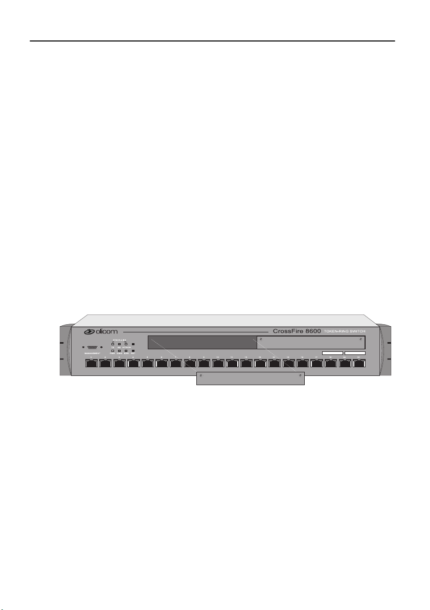
58
Installing a Universal Expansion Module
Follow these steps to install a Universal Expansion Module (UEM), if you have
received one.
1. If you have not already done so, unplug or remove power from the switch.
2. Remove the UEM from its box.
3. Remove the plate covering the Univ ersal Expansion S lot (UES) on the front of
the switch b y loosenin g the two thum bscre ws holding it in place. See Figure 14.
Use a screwdriver if the screws are too tight to be removed with your f ingers.
Retain the plate and thumbscrews for use in the event that the UEM is ever
removed.
4. Insert the card in the UES carefully, fitting each side into the card rails, and
making sure that the conne ctor on the card is seated in the connector at the back
of the slot.
5. Secure the card with the two thumbscrews attached to it. This is illustrated in
the publicati on that was shipped with the UEM.
6. It may be neces sary to download new mic r ocode to the switch in order to use a
specific UEM. Refer to the ins tr uctions that ca me wi th your UEM package.
Figure 14. Removing the Uni versal Expansion Slot Cover
CrossFire 8600/8605 Token-Ring Switches v. 1.2, P/N: 710001641 Installation
Page 75
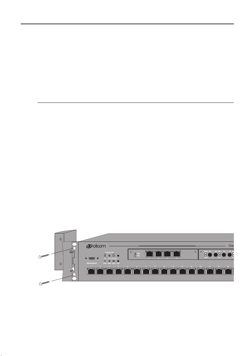
Mounting the Chassis
The switch can be mounted in a stan dard 19-inch rack or cabinet , or can be mounted
on any flat surface such as a tabletop. The installation area should be near a power
source and should have enough room around the f r ont and back panels for ca bling
and access to controls. Use the following procedures for the installation of the
switch.
59
➽ Warning:
replace this equipment.
Only trained and qualified personnel sho uld be allowed to insta ll or
Rack or Cabinet Mounting
If you install the equipment in a closed or multi-unit rack, observe the
environmental guidelines from the previous chapter, Chapter 3, “Preparing for
Installation”.
➽ Caution:
that the swit ch and any other equipment are mechanically stable.
The following steps describe how to mount the switch in a rack or cabinet:
1. Remove the bracket covers on each side of the switch to expose the rack
The following rack mounting instructions need to be observed to ensure
mounting brackets. Access to the retaining screws is obtained by opening the
cap on the front of each bracket cover. Use the Allen key supplied with the
switch to rem o ve the two 6 mm A llen sc rew s . When y ou ha ve removed t h e
screws, push the bracket cov er to war ds the ba ck of the switch and li ft the co ver
off. Keep the screws for later use.
Figure 15. Exposing the Rack M ounting Bracket
Before starting the next step, be sure you have the pr oper hardware for mounting
the chassis with the exposed brackets to your cab inet or rack.
CrossF ire 8600/8605 Token-Ring Switches v. 1.2, P/N: 710001641 Install ation
Page 76
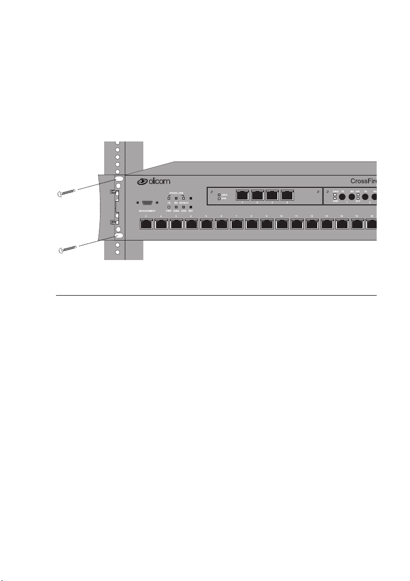
60
2. Position the switch, with the exposed mounting brackets, in the rack or cabinet
and slide it u p or do wn until the bracket holes l ine up with t he rack holes . Attach
the chassis brackets to the rack using the Allen screws you removed above and
the nuts supplied with the switch. Clos e the cap again to conceal the screws.
➽ Note:
Only fixed brackets are supplied with these units. If you want to install a
sliding pullout mount, you will need to provide the extra mounting hardware.
Figure 16. Mounting the Switch in a Rack or Cabinet
T a ble-Mounting
The swi tc h operates at a l ow noise leve l, which m akes it s uit ab le f or a work area o r
almost anywhere with a large enough fl at surface such as a table, desktop, or similar
area.
Four self adhe sive pads are s upplied with the s wit ch. Th e pads must be mounte d i n
the four recesses on the bottom of the switch. When the pads are mounted, simply
place the switch on a clear, level location. Leave enough room around the switch
for ventilation and access to the controls and cable connectors.
➽ Caution:
Due to weight constraints, place no more than three units (or the
equiv alent wei ght of othe r equipment) directly o n top of anothe r chassis. More than
three units on top of another unit may cause damage to the lower unit.
CrossFire 8600/8605 Token-Ring Switches v. 1.2, P/N: 710001641 Installation
Page 77

Cabling
This section provi des ins tructions for connecting devices (such as hubs, servers,
personal computers, and workstations) to the switch. Rem ember these t i ps when
connecting cables:
•
Avoid stretching or bending the cables excessively.
•
Avoid routing the cables near potential sources of electromagnetic
interference, such as motorized devices and fluorescent lights .
•
Avoid trip hazar ds by routing the cables away from aisles and other areas
where people walk. If suc h routes ca nnot be a void ed, us e floor c able co v ers or
similar material to secure and protect the cables.
•
Be sure that the cables connected to the switch are supported so that the cable
connectors are not excessively strained.
•
On
Cros sF i r e 8600
STP-A cable with an impedance-matching balun at each end.
•
On CrossFire 8605, the 20 fiber ports use VF-45 connectors. Note that these
are
compatible to the fi ber ST Duplex connectors on the Cros s Fire 8611
not
TokenRing UEM. Standard converter cables are needed.
, use a Category 3 or better UTP cable or a 150 ohm STP or
61
Connecting Devices to the Token-Ring Ports
If you will not be using building wiring (in-the-wall cables) to connec t the device
to the switch, perform the following steps. If you will be using building wiring,
follow the steps beginning with step 1 on page 62.
Follow these steps to connect one or more devices to the Token-Ring ports on the
switch:
1. If you have a UEM, connect it using the instructions in the documentation
shipped with it and then return here.
2. Using the switch Cabling Chart provided by your network administrator as a
guide, conne ct the cable s between the swit ch and othe r devi ces as il lust rated in
Figure 17. Note that the figure illustrates an RJ-45 connector on each end.
Depending on t he ca ble t ype you use, th e d evi ce en d of the c able ma y als o ha ve
a 9-pin D-shell or 150 ohm Data Connector.
3. If the switch is rack-mounted, dr ess the switc h end of the cables thr ough a cable
management brack et, if one is present on your rack.
4. Label each end of t he cable s so that it will be ea sy t o f ind the device if y ou ha v e
to troublesh oot a network problem.
Suggeste d inf ormation to place on the label includes the room location of the
CrossF ire 8600/8605 Token-Ring Switches v. 1.2, P/N: 710001641 Install ation
Page 78
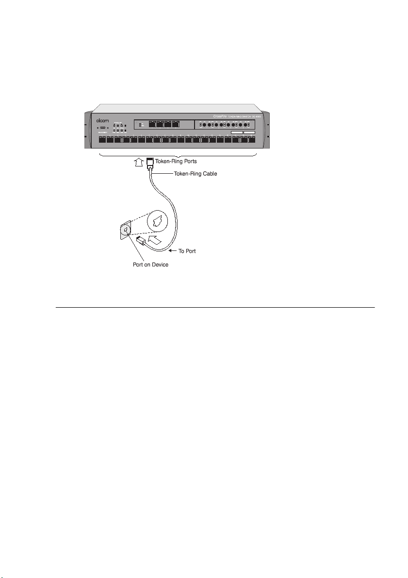
62
device at the oth er end, a uniqu e cab le ide nti ficat ion number, t he MAC add ress
of the connected device, and the number of the port to which the cable is
attached.
5. To continue instal ling the switch, go to “Applying Power” on page 64.
Figure 17. Connecting Devices to Token-Ring Ports
Connecting Devices to the Token-Ring Ports Using Building Wiring
If you will use building wiring (in-the-wall cab les) to connect the device to the
switch, p erf orm the following steps:
1. If you have a UEM, connect it using the instructions in the documentation
shipped with it and then return here.
2. Using the Switch Cabling Chart provided by your administrator as a guide,
connect the cables between the dev ices and the faceplate s as illustrated in
Figure 18.
3. Label the faceplate, so that it will be easier to find the device if you have to
troubleshoot a network problem.
4. In the wiring closet, connect a cable to the Token-Rin g connector on the patch
panel or other equipment where the building wiring terminates.
➽ Note:
CrossFire 8600/8605 Token-Ring Switches v. 1.2, P/N: 710001641 Installation
On CrossFire 8600, do not connect these cables to the Ring- In or Ring-Out
port on a media access unit (MAU) unless you use port 19 or 20 on the switch.
5. Connect the other end of the cable to a Token-Ring port on the switc h.
Page 79
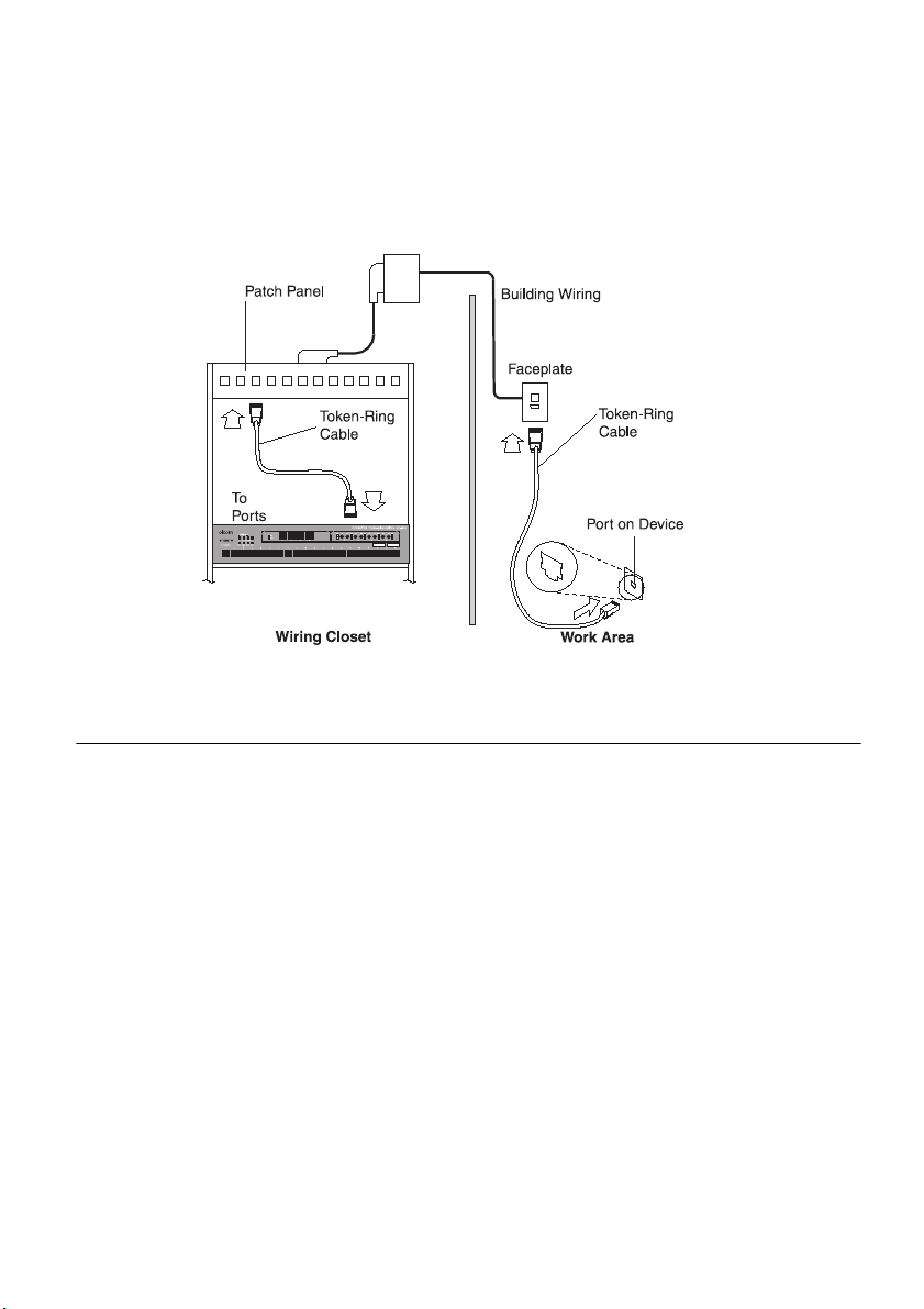
63
6. Label this cable.
7. If the switch is rack-mounted, dr ess the switc h end of the cables thr ough a cable
management brack et, if one is present on your rack.
8. To continue installing the switch, conti nue with “Applying Power”.
Figure 18. Connecting using Building Wiring
Checking the Installation
Before you apply power to the switch, inspect the installation thoroughly. Veri fy
that all cables are install ed correctly. Check cable routing, so a cable will not be
damaged or create a safety hazard. Be sure all equipment is mounted properly and
securely.
CrossF ire 8600/8605 Token-Ring Switches v. 1.2, P/N: 710001641 Install ation
Page 80
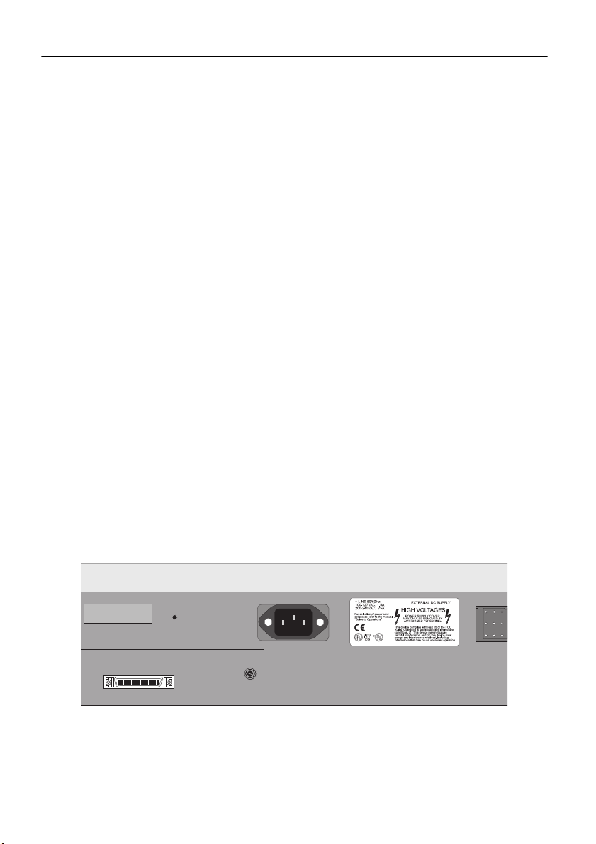
64
Applying Power
The switch chassis does not have an on/off switch.
plugged into a power source
.
There are no user se rviceabl e parts i nside a switc h. Any internal upgrades o r servic e
should be performed by Qualified Personnel
Power is on when the unit is
.
only
➽ Warning:
Unplug the power cord before you work on a system that does not have
an on/off switch.
➽ Warning:
When installing the uni t, the ground connection must al ways be made
first and dis connected last.
➽ Warning:
This equipment is intended to be grounded. Ensure that the host is
connected to earth ground during normal use.
➽ Warning:
Do not touch the power su pply when the power cord is conne cted. Line
voltages are present within the power supply when the powe r cord is connected.
Use the following steps to power on your equipment.
1. Ensure that you are using the cor rect power source.
2. Using a power cable that complies with nationa l regulations, plug the female
end of the cable into the AC power connector on the back panel of the switch
(see Figure 19).
3. Plug the male end of the power cord(s) into a properly grounde d ele ctrical
outlet.
Figure 19. The Back Panel of the Switch
CrossFire 8600/8605 Token-Ring Switches v. 1.2, P/N: 710001641 Installation
Page 81

65
4. V erify tha t the power LED is on. If not, mak e sure the outlet is worki ng properly .
If the outlet is w orkin g, b ut th e power LED and the fans are n ot on , see Chapt er
10, “Troubleshooting”.
5. When the switch powers on, observe the self-test diagnostic that the unit runs
for approxim ately 1-2 minutes. The DIA G LED is o n for th e duration of the test,
turning off when the self-test is complete.
6. At the completion of the diagnostics, the front pa nel LEDs should be
illuminated according to the st atus of the un it’ s con figur ation. See the follo wing
sections for a description of the controls and LEDs for the switch.
➽ Note:
If the swi tch fails to power up c orrectly or i f it encou nters any unreco v erabl e
error , the ERR LED will be on or flas hing on. If th e ERR LED is on or flas hes, s ee
Chapter 10, “Troubleshooting”.
➽ Caution
that thi s unit is
must be off
: If you are using the CrossF ire 8311 redundant power supply unit, note
hot-swappable. Both the CrossFire 8311 unit and the switch
not
before connecting or disconnecting the DC power cable.
CrossF ire 8600/8605 Token-Ring Switches v. 1.2, P/N: 710001641 Install ation
Page 82

66
Control Panels
The following t ables li s t and de scribe t he conne ctors , swit ches an d stat us LEDs on
the switch.
Front Panel
Table 17 and Table 18 lis t the front panel controls on the switch.
Connectors and Push-Buttons
Name Description
Ports 1 to 20
MANAGEMENT Console connection with DB-9 connector.
RST Reset—full system reset of software and hardware.
SYS REQ
(unlabeled)
Table 17. Front Panel Connectors and Push-Buttons
Cros sFire 8600:
UTP / S T P Token- R ing ports with RJ-45 ja c k s .
— Ports 19 and 20 can attach to a MAU/CAU RI/RO port.
Cros sFire 8605:
Fiber Token-Ring ports using VF-45 connectors.
— All 20 fibe r ports can at tach to a MAU/CAU RI/R O port .
— On CrossFire 8605, UTP/STP connections are only
available via the CrossFire 8610 Token-Ring UEM.
System Request—initiates a set of system request menus on
the attached console. If depressed for more than 5 seconds,
the swit ch will acce pt do wnl oad of t he ma in imag e from the
serial port via the X-modem protocol.
CrossFire 8600/8605 Token-Ring Switches v. 1.2, P/N: 710001641 Installation
Page 83

Status LEDs
LED State Meaning
67
PWR
DIAG
ERR
TX
RX
ATTACH
INS
(left LED of
port)
Off
On
On
On
or
On
blinking
or
On
blinking
On
On
Blinking
The switch is not connected to a power outlet, or
the power supply is faulty.
The sw i tch is receiv in g power.
The DIAG diagnostics LED is on during the
power-o n self-test. During download of a new
software ima ge, th e DIAG LED blink s to indi ca te
the clearing (slow blink) and reloading (faster
blink) of FLASH memory.
The ERR LED is off during normal operation. If
the LED turns on, an error has occurred. Power the
switch down and up again. The ERR LED should
not turn on again.
Note th a t th is LED tur n s on if th e switch is
powered from a redundant power supply only.
Data is being transmitted to the stack link.
Data is being received from the stack link.
A connection has been established to the stack.
The Token- R ing port is inser t ed into the ring.
The port is disable d.
ACT
(right L ED of
or
On
blinking
Data is being transmitted to or received f r o m the
port.
port)
Table 18. Front Panel LEDs
CrossF ire 8600/8605 Token-Ring Switches v. 1.2, P/N: 710001641 Install ation
Page 84

68
Back Panel
Table 19 lists the ba ck panel connectors on the switch.
Name Description
AC connection Standard AC power connection.
Redundant pow er
supply
Table 19. Back Panel Switches and Connectors
Connector for the opti onal redundant power supp ly unit.
❏
CrossFire 8600/8605 Token-Ring Switches v. 1.2, P/N: 710001641 Installation
Page 85

5. Connecting a Network Management Console
Console interfacing can be established by connecting to the MANAGEMENT
serial port on the front panel of the CrossFire 8600 Token-Ring Switch a nd/or the
CrossFire 860 5 Toke n-Ring Fiber Switch. Use this connect ion to set up in-band
management , which is the management of the swi tch
of-band management, which is management
outside
through
of the network:
the network, or out-
69
•
In-band manag ement
network:
— Ol icom Switch Manager for HP OpenView for Windows
— Other Simple Network Managem ent Protocol (SNMP) ba sed applications
— Telnet sessions
•
Out-of-band management
session for configuring and monitoring sw itches.
Network managemen t a pplica tions (in-ba nd mana gement) a re bey ond t he scope of
this guide. Se e the
Operations
application. How to connect the serial console (out-of-band management) for
configuring and monitoring the switch is described in this chapter.
Refer to the section “Console/Telnet Sessions” on page 130 for information on
configuring serial console and/or telnet console sessions.
or the documentation supplied with you network management
is a network management syste m that works through the
is a direct console connection to create a console
Olicom Switch Manage r for HP OpenView—Guide to
Connec ting the Co nsole
The following steps explain connecting a serial terminal to the switch:
1. Connect the switch to a PC or other DTE (Data Terminal Equipment) devic e
using a straight , 25-pin to 9-pin TIA/EIA-232 ca ble (common ly known as a RS232 cable) and a null modem adapt er or a 9-pi n to 9-pi n ca ble. Se e Appendi x B
for a description of the ca bles and adapters.
2. Connect the TIA/EIA-232 cable to the DB-9 MANAGEMENT connector on
the front panel of the switch. This male DB-9 connect or on the switch is
configured as a DTE device.
See Figure 20 to view the locat ion of the cab le connection on the front panel of t he
switch.
CrossF ire 8600/8605 Token-Ring Switches v. 1.2, P/N: 710001641 Connecting a Net work Management Console
Page 86
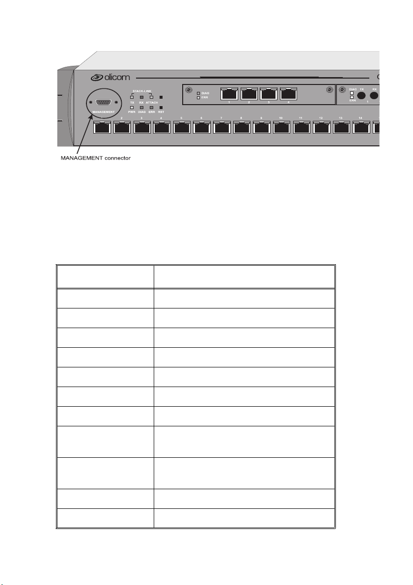
70
Figure 20. View of Console Connection—the MANAGEM ENT port
The next step and table describe the settings to use for configuring a console in
order to communicate with the switch.
3. Use these values to set the configuration parameters on your console for
interfacing to the swi tch.
Specification Value
Baud Rate 2400, 4800, 9600, 19200, 38400, 57600
Parity None
Data bits 8
Stop bits 1
Handshaking None
Terminal emulation VT100
Duplex Full
Software flow control
Off (input and out put)
(XON/XOFF)
Hardware flo w
Off
control (R TS/CTS)
Autobaud upon break On
Line wrap On
T able 20. Console Configuration Settings
CrossFire 8600/8605 Token-Ring Switches v. 1.2, P/N: 710001641 Connecting a Network Management Console
Page 87

Specification Value
Screen scroll On
CR translation CR
71
Backspace (BS)
Destructive
tran slation
Break length
350
(millis econds)
Enquiry (ENQ) Off
EGA/VGA true
Off
underline
Terminal w idth 80
ANSI 7 or 8 bit
7
commands
Microsoft Windows
™ termin al
emulati on
Table 20. Console Configuration Settings
Disable the
Ctrl Keys for Windows
Use Function, Arrow, and
option located in
the Terminal Preference menu
4. At power on (cold boot), the switch performs a series of self-test diagnos tics
verifying t hat hardware component s are functioning. An example of the self-t est
diagnos tic screen is s h own later in t his chapter.
Communication Problems
If the diagnost ic list does not appear, or is garbled, try adjusting th e baud rates
between the console and the switch by using the Autobaud routine within the
switch. To do this, press the reset button on the front of the switch and wait for the
internal diagnostics to finish (the DIAG LED turns off). The reason for the reset is
that in case the switch’s Autobaud routine is not enabled, resetting it will set it to
its default mod e of Autobaud enabled.
Depending on the ty pe of console, there are seve ral console command keys that will
potentially initiate the Autoba ud routine in the switch. Four of those keys are
RETURN
, the combination keys of
ALT-B
, the
BREAK
key, and
ESC
.
After the DIAG LED goes out, try one these command key s at the console, and
press it repeatedly. If there is no response, wait several seconds and again, press it
repeatedl y. If necessary, perform the same routine using the other command keys.
CrossF ire 8600/8605 Token-Ring Switches v. 1.2, P/N: 710001641 Connecting a Net work Management Console
Page 88

72
If that does no t work, and there is at l east a ga rbled output on the s creen, try pushing
the unlabelled system request button on the switch. As soon as garbled characters
appear, press the co nsole’s
RETURN
key twice in rapid suc cession. (Again, try the
other command keys as necessary).
If there is still a problem, try the following steps:
1. Check all of the cable connections.
2. Check the baud rate at the console’ s set up screen; if it i s not set to 9600, try that
setting.
3. Try setting the console baud rate to different val ues up or down, and pressing
RETURN
for each selection.
4. If you are using a terminal emul ation program, try exiting the program and
restarting.
5. If you still can not get the connection to work, cont act technical supp ort as
described in
Chapter 11, “Getting in Touch with Technical Support”
Diagnostic Screen
The diagnostic self-test displays two different screens (lists of informati on),
depending on whether you perform a cold boot (power on cycle with full
diagnostics), or a warm boot (a reset without full diagnostics).
.
During a cold boot, the following abbreviated lis t is an
example
of messages
(depending upon several factors, such as hardware, options, software version
levels) that appears on the consol e screen a s the test s are pe rformed. The wa rm boot
contains port ions of the complete cold boot list.
The foll owing is a n
example
of a diagnostic screen duri ng a boo t process (the act ual
screen may vary depending on such things as hardware, options, software version
levels and other factors):
BootStrap Firmware v2.3, Copyright 1996-1998
- Initiating bootstrapping sequence.
- Boot image integrity check...Passed.
- Control transferred to boot process.
Boot Firmware (Phase II) v2.3
- Program memory test........Passed.
- Relocating main image to
DRAM.......................................Done.
- Main image integrity check...succeeded.
- Control transferred to main process.
- Starting Power On Self Test Diagnostics.
CrossFire 8600/8605 Token-Ring Switches v. 1.2, P/N: 710001641 Connecting a Network Management Console
Page 89

73
- Network memory test 32-bits........Passed.
- Network memory test 16-bits........Passed.
- Network memory test 8-bits........Passed.
- Port register and memory test.....................Passed.
- Single port loopback test.....................Passed.
- All ports linked loopback test.....................Passed.
- Port MAC test.....Passed.
- Completed Power On Self Test Diagnostics.
System Software Version 03.05, Copyright 1994-1998.
System started on Tue. November 10, 1998 14:30:03
8 Megabytes System memory
2 Megabytes Network memory
- Initialization started
- File system initialized
- System temperature is within safe operating levels
- Checking file system integrity
- Warmboot initialization started
- LAN ports detected:
- RJ-45 Token Ring: 1 2 3 4 5 6 7 8 9 10 11 12 13 14 15 16 17 18 19 20
- StkPort : 29
- Initializing Ports: 1 2 3 4 5 6 7 8 9 10 11 12 13 14 15 16 17 18 19
20 29
- Initializing system address table
- System entering stand-alone mode
- System initialization complete
Starting SNMP v1/v2c bilingual agent task
Total MIB objects: 1236
- Enabling port: 1 2 3 4 5 6 7 8 9 10 11 12 13 14 15 16 17 18 19 20 29
Press RETURN key to activate console...
Depending upon which tests have run, verify that al l diagnostics have passed and
that the ERR LED is o ff. If t he ERR LED is o n, read t he screen t o determine which
test failed. See also
Chapter 10, “Troublesh ooting”
At the end of the boot messages, you should be prompted to press
, to help fin d th e ca use.
RETURN
. The
following greeting screen of the switch Console Manager should appear:
CrossF ire 8600/8605 Token-Ring Switches v. 1.2, P/N: 710001641 Connecting a Net work Management Console
Page 90
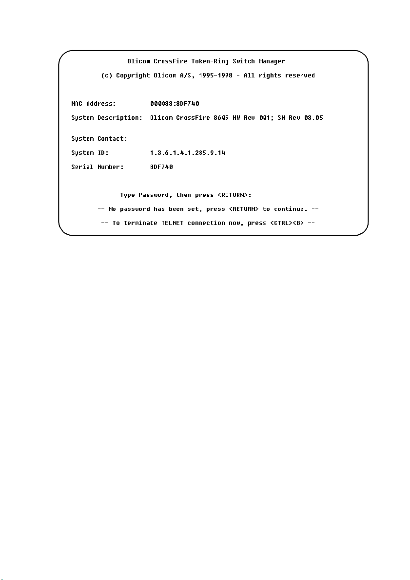
74
At the top level scre en, press the
key (also called
ENTER
RETURN
) to enter the main
menu. The contents of the main menu, the submenus and screens are described in
subsequent chapters. The information in these chapters includes configuring,
monitoring, and viewing statistics on th e s witch.
➽ Note:
If you hav e forgotten the pass word, follow the description in the
page 129.
Note
on
❏
CrossFire 8600/8605 Token-Ring Switches v. 1.2, P/N: 710001641 Connecting a Network Management Console
Page 91

6. Switch Configuration
This chapter explains how to set up th e CrossFire 8600 Token-Ring Swi tch or the
CrossFire 860 5 Toke n-Ring Fiber Switch and how to modify the configuration
using a VT100 console attached to the switch directly or via a modem connection .
The switch conf igur ation c an also be modifie d from a remo te VT100 cons ol e via a
telne t s es sion.
Subjects covered in this chapter:
•
General guidelines (pa ge 76)
•
Main menu screen (page 78)
•
Configuration menu (page79)
•
Switch and stack configuration (page 81)
•
Module Information (page 85)
•
Virtual LANs (page 87)
•
IP Configuration (page 94)
•
Spanning Tree Protocol (STP) (page 97)
•
Port Configuration (page 105)
75
•
CrossLink channels (page 109)
•
Address filter ing (page 115)
•
Address aging (page 125)
•
Console Password (page 129)
•
Console/telnet sessions (page 130)
•
Download/Upload menu (page 137)
•
Reset menu (page 142)
CrossF ire 8600/8605 Token-Ring Switches v. 1.2, P/N: 710001641 Switch Configuration
Page 92

76
General Guidelines
To work within the console menus and screens, follow these guidelines:
•
To select an item on a screen or a menu, highlight it by using the arrow keys
and then press
item—for example, selecting
appears on the scree n.
•
In most cases, new values are save d when you select
•
The
screen. Selecting
information.
item means th ere is more info rmation t han what is di spla yed on tha t
More
. If you need to specify additional information for that
ENTER
or No or supplying a
Yes
and pressing
More
displays the ne xt screen of
ENTER
value
Return
—a prompt
.
•
•
•
•
•
•
•
•
•
refers to the number of a specif ic port on a switch.
Port
refers to the numerical order of a list.
Index
To return to the main menu from any screen, press
changes made to the screen you were in will not be saved when you do this.
To return to the greeting screen, press
To refresh the console screen, press
If you are administering switches i n a stack, many of the console s creens will
prompt for a box number. Enter the number of the box you want to ad minis ter.
The “VLAN” term in connection with CRF is discussed on page 26.
The terms “Virtu al LA N ” an d “d om ai n ” ar e in t er c h an g ea bl e .
The console automatically returns to the greeting screen after five minutes of
inactivity. Five minutes is the default value. The time can be changed at the
Console Configuration
Console Configuration
then se lect
For protection against inadve rtent or unauthorized acc ess to configuration
screens, you may est ablish a password that users must enter at the greeting
screen. If no password is configured, just press
presented . To establish a password, s ee the section “Password Menu,” later in
this chapt er. To open the
menu and then select
explanat ion on the greeting screen, see Chapter 5, “Connecting a Netw ork
Management Console”.
Console Configuration...
menu as explained later in this chapter. To open the
menu, select
Password
Password...
CTRL-L
Configuration...
in the
menu, select
in the
.
CTRL-B
.
Configuration
ENTER
Configuration...
Configuration
. Note that any
CTRL-P
in the ma in menu and
menu.
and the main menu is
in the main
menu. For more
CrossFire 8600/8605 Token-Ring Switches v. 1.2, P/N: 710001641 Switch Configuration
Page 93

77
Navigating within the Menus
Use the arrow keys (also referred to as cursor keys) to highlight an item on the
screen or menu.
•
Items that end with three dots, opens another screen or menu. Pressing the
key on such an item will display the new screen or menu.
ENTER
•
If the item on the screen is a command, such as
will execute the command.
Unless spe cifie d differ ently, a ll the screens a nd menus are acc essed in the s a me w a y.
The following s ection describes the items on the main menu.
Reset
, pressing the
ENTER
key
CrossF ire 8600/8605 Token-Ring Switches v. 1.2, P/N: 710001641 Switch Configuration
Page 94
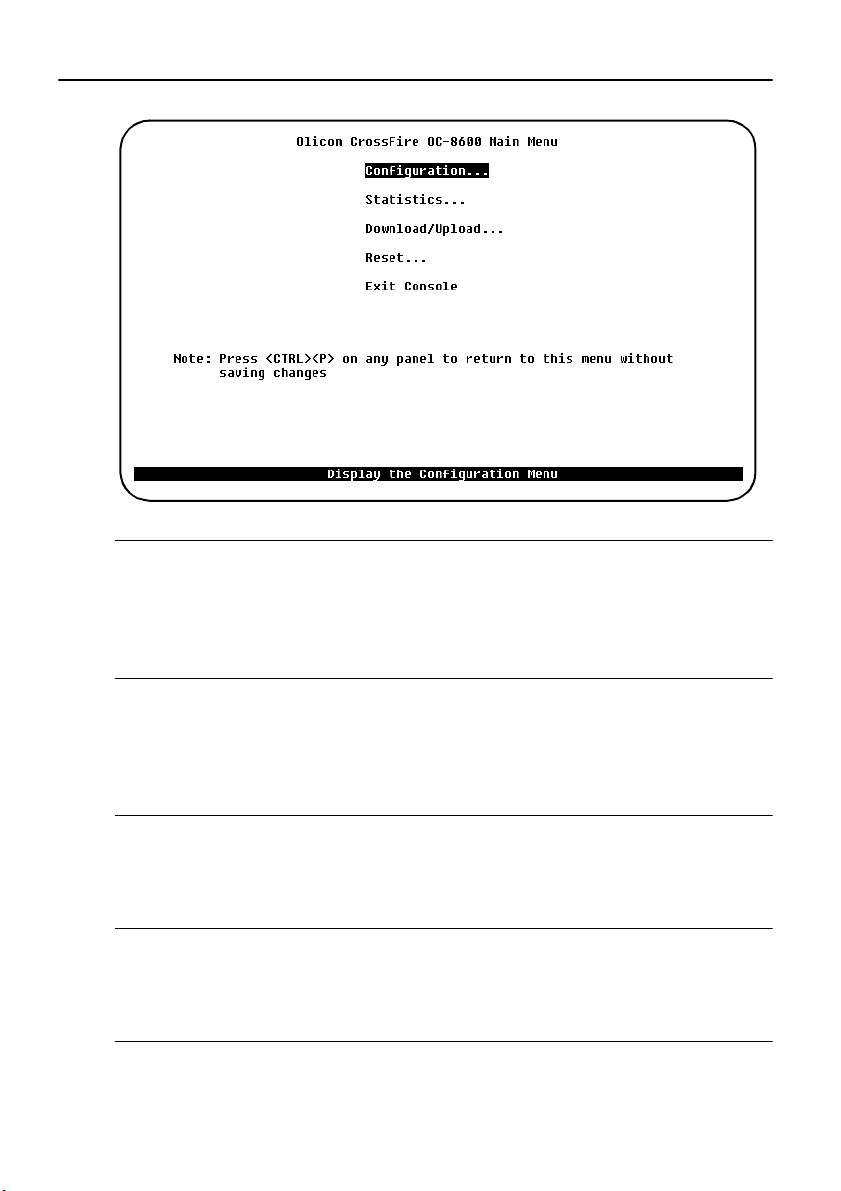
78
Main Menu
Configuration...
Displays the
configuration paramete rs. A de taile d expla nation of the configura tion su bmenus is
given on page 79.
Configuration
menu, which enables you to view and set the switch
Statistics...
Displays the
Statistics
page 145.
menu are in Chapter 7, “Monitoring the Network with the Console ” on
Statistics
menu for the switch. Explanat ions of screens in th e
Download/Upload...
Displays the
after the sections describing the
Download/Upload
menu that is explained in thi s chapter immedia tely
Configuration
menu. See page 137.
Reset...
Displays the
describing the
menu that is explained in this chapter after the sections
Reset
Download/Upload
menu. See page 142.
Exit Console
Highlighting this command and pressing
greeting scree n (on a Telnet session, this will cause the session to close).
CrossFire 8600/8605 Token-Ring Switches v. 1.2, P/N: 710001641 Switch Configuration
will return the console to the
ENTER
Page 95
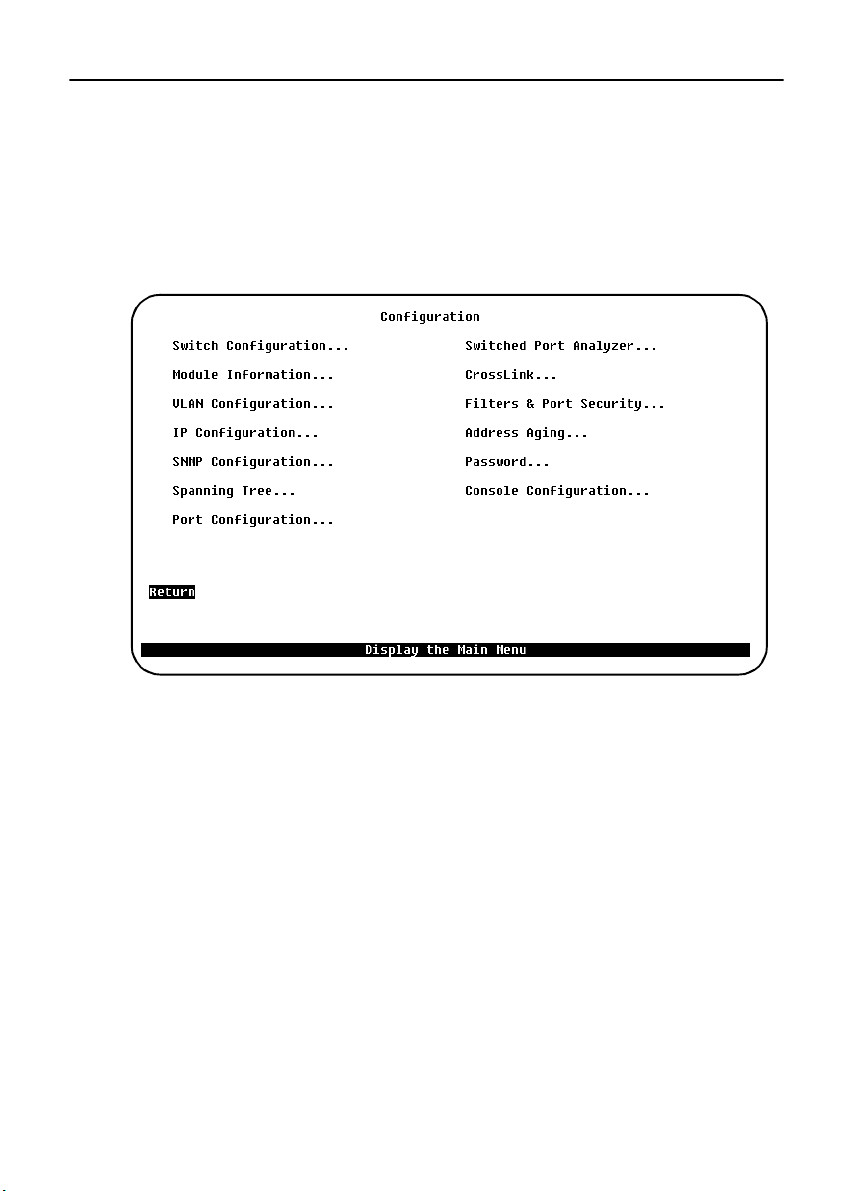
Configuration Menu
From the
parameters. Th e following section describes the
submenus.
Configuration
menu you can view and set the switch configuration
Configuration
79
menu and its
The following menu is displayed when
menu.
The following is a list of items in the
and of the submenus and scre ens these items open follow thi s list.
Switc h Co nf ig ura t io n...
Displays the
Switch Configuration
Configuration
Configuration
screen. See page 81.
is selec t ed fr o m th e main
menu. Detailed descriptions
Modu le Inform a t ion...
Displays information regarding optional expansion modules. See page 85.
VLAN Configuration...
Displays options for configuring BRFs and CRFs. See page 87.
IP Configuration...
Displays a screen for changing IP addresses, gateways and subnet masks and for
sending a PING. See page 94.
SNMP Configura t io n...
Displays fields for setting attributes related to SNMP. See page 184.
CrossF ire 8600/8605 Token-Ring Switches v. 1.2, P/N: 710001641 Switch Configuration
Page 96

80
Spanning Tree...
Displays fields for configuring the spanning tree protocol. See page 97.
Port Configuration...
Displays a screen for changing port configuration. See page 105.
Switched Port Analyzer...
Displays the screen for selecting a port to monitor. See page 193.
CrossLink...
Displays options for creating a CrossLink connection. See page 109.
Filters and Port Security...
Menu for configuring address and protocol filte ring. See page 115.
Address Aging...
For setting a different aging time for the address tables in memory for the system
and ports. See page 125.
Password...
Displays a screen for se tting up and changing the password for a ccess to the
console. See page 129.
Console Configuration...
Displays choices for setting up console or Telnet sessions with the switch. See
page 130.
CrossFire 8600/8605 Token-Ring Switches v. 1.2, P/N: 710001641 Switch Configuration
Page 97
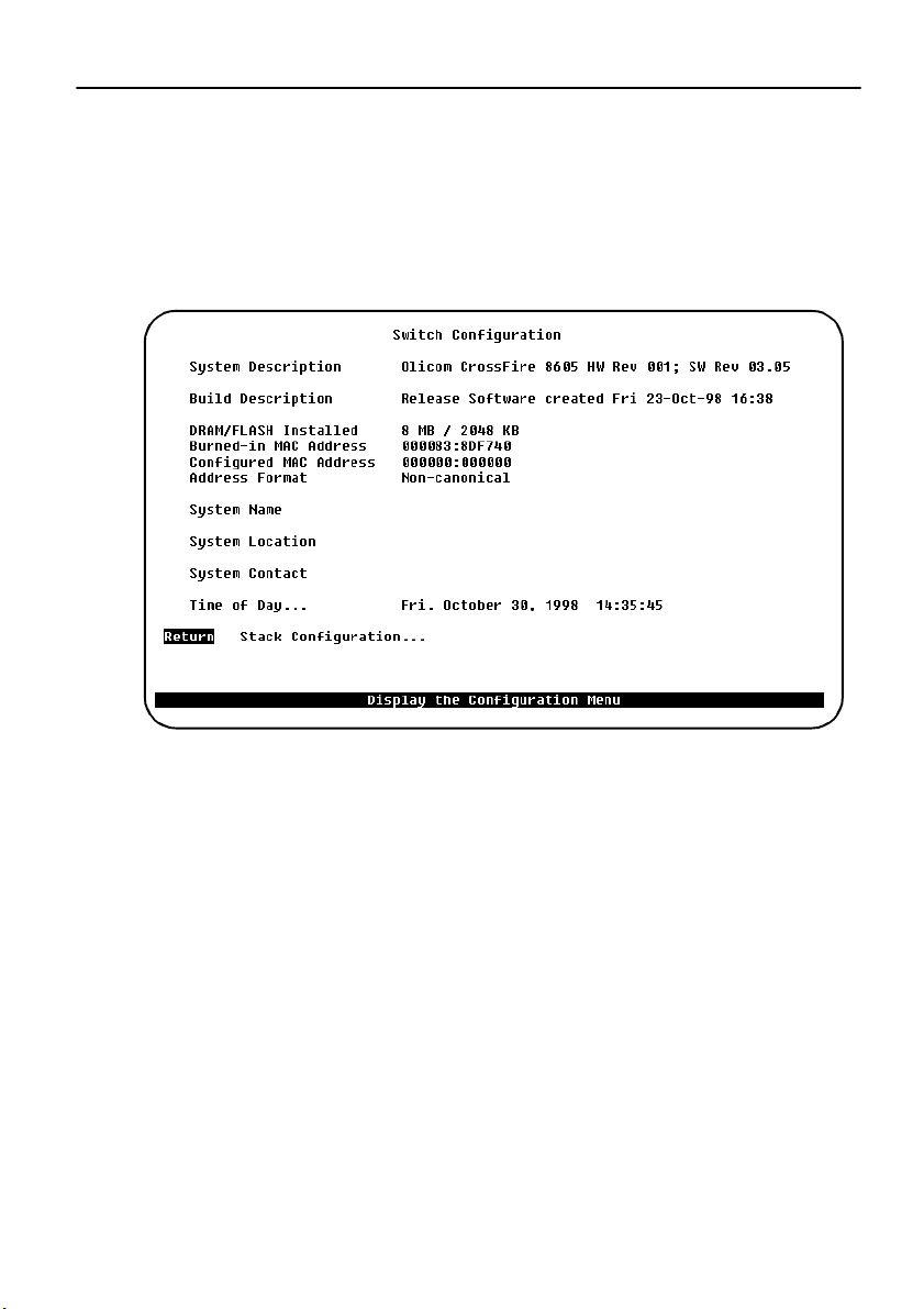
Switch Configuration Screen
Use the
Switch Configuration
change the system name, location, contact, and time of day. To add or change the
system name, location, contact or time of day, use the arrow keys to high light the
field and press the
ENTER
entering text for that field. Pressing
screen to view syst em information and to view or
key. A prompt appears near the bottom of the screen for
again ent er s th a t te xt .
ENTER
81
The following ex plains the fields in the
Switch Configuration
screen.
System Description
Name and model of this switch. Information in this f ield cannot be changed.
Burned-in MAC Address
The factor y-assigned base MAC addres s of the switch. Information in thi s field
cannot be changed.
Configured MAC Address
The MAC address that is currently in use, or, if a new MAC address has been
configured, the MAC address that will be used after the next boot. If a locally
administered address is assigned to the switch, this field displays that address.
Otherwise, the field displays
000000:000000
. To assign a locally administered
address, sele ct this field, and enter the new address. Note that the switch occupies
this, the bas e MAC address, and the next 96 addresses.
All usage of MAC-Address es in t he switch is ba sed upon o ne address . This ad dress
is denoted the Switch Base address and can be either Burned-in (The factory
CrossF ire 8600/8605 Token-Ring Switches v. 1.2, P/N: 710001641 Switch Configuration
Page 98

82
assigned Universal Adm inistrated Address UAA) or configured (the Local
Administrated Address LAA). To configure a LAA address, use the
Configuration
Note that a restart is necessary when changing the base MAC address.
The greeting scree n on the console wil l always show the curre nt active Swit ch base
Address.
The switch reserves 31 address es for ports.
The Token-Ring ports on a switch switch will be assigned MAC addresses using
the following scheme:
•
BASE Module port 1- 20 Will be assigned Switch Base Addr es s + port
•
LEFT UEM port 1-4 Will be assi gned Switch Ba se Address + 20 +
•
RIGHT UEM port 1-4 Will be assig ned Switch Base Address + 24 +
OR:
A Token-Ring port wi ll be assi gned a MAC addres s, which is Swit ch Base Address
+ the port number dis play ed on the po rt c onfigura tio n screen (or inte rface ta ble for
SNMP).
screen from a cons ole ses sion or an SNMP ba sed managem ent tool.
number
port number
port number
Switch
This MAC address is used for the Token-Ring MAC protoc ol, and for the spanni ng
tree protocol.
The switch reserves 63 addresses for TrBRF ( VLAN).
Each VLAN has an attached B r idge relay function (TrBRF) and a Management
entity (IP -protocol st ack), an d consequent ly it needs a MAC Address. I n the swi tch,
these two logical units use the same address, ho wever this address must be unique
in the network. This is ensured by assigning MAC address to TrBRF’s from the
Switch Base Address + 32 (0x20) and upwards. The switch is design ed in such a
way, that it operates with 63 ac tive or preferred VLAN’s, implying that 63 MAC
addresses need to be reserved for TrBRF.
Summarizing each CrossFire 8600 reserve: Swit ch Ba se Address + 31 Addresses
for Token-Ring ports + 63 MAC Addre sses f or TrBRFs = 95, whic h is rounded up
to 96 or hexadecimal 0x60.
The MAC address of the default TrBRF (trnet-default) will always be the switch
base address + 32. If the swi tch operates in a stack, only one of th e switches will
operate the brid ge re lay function. Hence the MAC address of the default TrBRF
will be the base addr ess of the sta ckmast er + 32. The stackm aste r is determin ed by
software, when the sta ck consists of two switches back to back and by the port
CrossFire 8600/8605 Token-Ring Switches v. 1.2, P/N: 710001641 Switch Configuration
Page 99

83
numbers in 8300/8635 stack configuratio ns.
There is no s imple rul e t o f ind the MAC addre ss of othe r Tr BRF, but it i s always in
the range below:
Stack Master Base Address + 32 < TrBRF M AC Address < Stack Master Base
Address + 95. And a TrBRF (VLAN) MAC address is assigned, when the
VLAN b ecomes pref er r e d ( i. e. it has an as si g ned port in the ac tu al switch o r
stac k o f switches) b y select in g the lowes t available MAC address above Stack
Master Base Address + 32.
If management (SNMP or TELNET) contact with the switch is lost (e.g. because
ports are moved from one TrB RF to another) it is suggested, that a terminal is
connected to the OBM port of the switch stack, and the IP Configuration menu is
entered. From here , it is possible to re ad the MAC address of the managem ent entity
(TrBRF).
Address Format
Display format used for MAC addresses (canonical or non-canonical). Canonical
format is typic ally us ed in Et hernet networks and is also kno wn a s least signi f icant
bit fi rst. Non-canon ical is typi cally us ed in Token-Ring networks and is also kno wn
as mo s t si gnific ant bit first.
System Name
Any name you choose t o assig n to the s wit ch (on a TCP/IP ne twork , it c oul d be th e
IP hostname).
System Location
Physical loca ti o n o f th e swi tch.
System Contact
Person to contact if questions should arise.
DRAM Installed
Amount (in MB) of dynamic memor y installed. Information in this fiel d cannot be
changed.
Flash Memory Installed
Amount (in KB) of flash memory installed. Information in this f ield cannot be changed.
CrossF ire 8600/8605 Token-Ring Switches v. 1.2, P/N: 710001641 Switch Configuration
Page 100
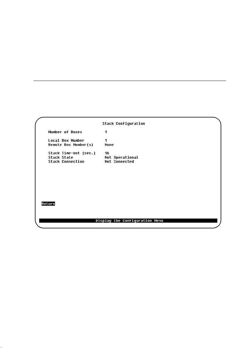
84
Time of Day
An internal cloc k is use d to calculate total time of operation and time of day. To
adjus t th e time, sele ct th is item, pre ss
, then enter the month, day, hour, or
ENTER
minute.
➽ Note:
If you cannot set the
Time of Day
this is the case, contact your local reseller.
Stack Configuration Screen
To view additi onal switc h info rmation, sele ct
Configuration
screen. The
Stack Configuration
, the lit hium ba ttery may need re pl acing. If
Stack Configuration
on the
Switch
screen is displayed.
The following information is displayed on this screen:
Number of Boxes
Number of switches currently participating in the stack. Inf ormation in this field
cannot be changed.
Local Box Number
Number assigned to the switch to which the console is connected. Th e local box is
also the source of the informati on displayed on th is screen . Informatio n in this fie ld
cannot be changed.
CrossFire 8600/8605 Token-Ring Switches v. 1.2, P/N: 710001641 Switch Configuration
 Loading...