


-
TI CRYOG
C
HELIX TECHNOLOGY CORPORATION
EN
9600 Compressor Installation, Operation, and
Maintenance Instructions
ICS
8040540
Rev. 101 (12/2004)
HELIX TECHNOLOGY CORPORATION
http://www.helixtechnology.com

ELIXH
The information in this documen t is believed to be accurate and reliable. However,
Helix Technology Corporation, cannot accept any financial or other responsibilities that may
result from the use of this infor mation. No warranties are granted or extended by this
document.
Helix Technology Corporation reserves the right to change any or all information contained
herein without prior wri tten notice. Revisions may be issued at the time of such changes
and/or deletions .
Any duplication of this manual or any of its parts without expressed written permissi on from
Helix Technology Corporation is strictly prohibited.
Any correspondence regarding this document should be forwarded to:
Helix Technology Corporation
Mansfield Corporate Center
Nine Hampshire Street
Mansfield, Massachusetts 02048-9171 U.S.A.
Telephone: (508) 337-50 00
FAX: (508) 337-5464
The following Helix Technology Corpor ation trademarks and service marks may appear in
this document:
Conductron
Cryogenerator
GOLDLink
Helix Technology..
Your Vacuum Connection
On-Board
Stabil-Ion
Vacuum Assurance
®
®
®
®
®
SM
Convectron
Cryo-Torr
Granville-Phillips
Micro-Ion
SM
RetroEase
ThinLine™
®
®
®
®
®
Cryodyne
CTI-Cryogenics
GUTS
Mini-Convectron
RetroFast
TurboPlus
®
®
®
®
®
®
Cryogem
FastRegen™
Helix
Mini-Ion™
Stabil-1
TrueBlue
®
®
®
SM
All other trademarks or registered trademarks are the property of their respective holders.
©2004 Helix Technology Corporation Printed in USA


9600 Compressor Installation, Operation, and Maintenance
Table of Co nt ents
Section 1 - 9600 Compressor Description
Genera l . . . . . . . . . . . . . . . . . . . . . . . . . . . . . . . . . . . . . . . . . . . . . . . . . . . . . . . . . . . 1-1
Benefi t s . . . . . . . . . . . . . . . . . . . . . . . . . . . . . . . . . . . . . . . . . . . . . . . . . . . . . . . . . . 1-1
Compressor Conf i g u rations . . . . . . . . . . . . . . . . . . . . . . . . . . . . . . . . . . . . . . . . . . . 1- 1
Syste m Do c u m e n t a t i o n . . . . . . . . . . . . . . . . . . . . . . . . . . . . . . . . . . . . . . . . . . . . . . 1-2
CTI-CRYOGENICS Helium Refrigeration System . . . . . . . . . . . . . . . . . . . . . . . . 1-2
Specificatio n s . . . . . . . . . . . . . . . . . . . . . . . . . . . . . . . . . . . . . . . . . . . . . . . . . . . . . . 1-4
Dimensions . . . . . . . . . . . . . . . . . . . . . . . . . . . . . . . . . . . . . . . . . . . . . . . . . . . . 1-4
Weigh t . . . . . . . . . . . . . . . . . . . . . . . . . . . . . . . . . . . . . . . . . . . . . . . . . . . . . . . . 1-5
Elect r i c a l . . . . . . . . . . . . . . . . . . . . . . . . . . . . . . . . . . . . . . . . . . . . . . . . . . . . . . 1-5
Coolin g Wa t e r . . . . . . . . . . . . . . . . . . . . . . . . . . . . . . . . . . . . . . . . . . . . . . . . . . 1-6
Genera l . . . . . . . . . . . . . . . . . . . . . . . . . . . . . . . . . . . . . . . . . . . . . . . . . . . . . . . . 1-7
Component Description . . . . . . . . . . . . . . . . . . . . . . . . . . . . . . . . . . . . . . . . . . . . . . 1-8
System Circuit Breaker . . . . . . . . . . . . . . . . . . . . . . . . . . . . . . . . . . . . . . . . . . . 1-9
Control Circuit Breaker . . . . . . . . . . . . . . . . . . . . . . . . . . . . . . . . . . . . . . . . . . . 1-9
Power ON In d i c ator . . . . . . . . . . . . . . . . . . . . . . . . . . . . . . . . . . . . . . . . . . . . . . 1-9
Gas Charg e F lared Fit ti n g . . . . . . . . . . . . . . . . . . . . . . . . . . . . . . . . . . . . . . . . . 1-9
Helium Pressure Gauge . . . . . . . . . . . . . . . . . . . . . . . . . . . . . . . . . . . . . . . . . . . 1-9
Power Inlet . . . . . . . . . . . . . . . . . . . . . . . . . . . . . . . . . . . . . . . . . . . . . . . . . . . . . 1-9
Return G as Co u p l i n g . . . . . . . . . . . . . . . . . . . . . . . . . . . . . . . . . . . . . . . . . . . . 1-10
Coolin g Wa t e r IN . . . . . . . . . . . . . . . . . . . . . . . . . . . . . . . . . . . . . . . . . . . . . . . 1-10
Coolin g Wa t e r OUT . . . . . . . . . . . . . . . . . . . . . . . . . . . . . . . . . . . . . . . . . . . . . 1-10
Cryopump Electrical Outlet . . . . . . . . . . . . . . . . . . . . . . . . . . . . . . . . . . . . . . . 1-10
Cryopump Power Phase Switch . . . . . . . . . . . . . . . . . . . . . . . . . . . . . . . . . . . . 1-11
Compressor Remot e Co n n ec t o r . . . . . . . . . . . . . . . . . . . . . . . . . . . . . . . . . . . . 1-11
Supply Gas Coupling . . . . . . . . . . . . . . . . . . . . . . . . . . . . . . . . . . . . . . . . . . . . 1-11
Multiple On-Board Cryopump Connections . . . . . . . . . . . . . . . . . . . . . . . . . . . . . 1-11
Multiple Cryo-Torr Cryopump Connections . . . . . . . . . . . . . . . . . . . . . . . . . . . . . 1-13
Section 2 - Unpacking and Inspection
Introduction . . . . . . . . . . . . . . . . . . . . . . . . . . . . . . . . . . . . . . . . . . . . . . . . . . . . . . . 2-1
Shipping Carton Inspection . . . . . . . . . . . . . . . . . . . . . . . . . . . . . . . . . . . . . . . . . . . 2-1
Removal fr o m Sh i p p i n g C arton . . . . . . . . . . . . . . . . . . . . . . . . . . . . . . . . . . . . . . . . 2-1
Compre ssor Inspe ction . . . . . . . . . . . . . . . . . . . . . . . . . . . . . . . . . . . . . . . . . . . . . . 2-2
Compre ssor . . . . . . . . . . . . . . . . . . . . . . . . . . . . . . . . . . . . . . . . . . . . . . . . . . . . 2-2
Helium St at ic Pressu re Verif i c a t i o n . . . . . . . . . . . . . . . . . . . . . . . . . . . . . . . . . 2-2
Shippin g Carton Co n te n ts . . . . . . . . . . . . . . . . . . . . . . . . . . . . . . . . . . . . . . . . . 2-2
P/N 8040540 4

9600 Compressor Installation, Operation, and Maintenance
Table of Contents (continued)
Section 3 - Installation
Introduction . . . . . . . . . . . . . . . . . . . . . . . . . . . . . . . . . . . . . . . . . . . . . . . . . . . . . . . 3-1
Supply and Return Water Line Connections . . . . . . . . . . . . . . . . . . . . . . . . . . . . . . 3-3
Hard Water Lines . . . . . . . . . . . . . . . . . . . . . . . . . . . . . . . . . . . . . . . . . . . . . . . . 3-3
Flexib le Water Li n e s . . . . . . . . . . . . . . . . . . . . . . . . . . . . . . . . . . . . . . . . . . . . . 3-3
Elect r i c a l Co n n e ctions . . . . . . . . . . . . . . . . . . . . . . . . . . . . . . . . . . . . . . . . . . . . . . . 3-4
Power Cable Prep a ration . . . . . . . . . . . . . . . . . . . . . . . . . . . . . . . . . . . . . . . . . . 3-4
Phase Ch e ck . . . . . . . . . . . . . . . . . . . . . . . . . . . . . . . . . . . . . . . . . . . . . . . . . . . . 3-6
Cryopump Power Phase Switch Setting . . . . . . . . . . . . . . . . . . . . . . . . . . . . . . 3- 7
Connecti n g /Disc o nn e c t i n g He li u m Fl ex Lines . . . . . . . . . . . . . . . . . . . . . . . . . . . . 3 -7
Conne c t i n g . . . . . . . . . . . . . . . . . . . . . . . . . . . . . . . . . . . . . . . . . . . . . . . . . . . . . 3-7
Disconnecting . . . . . . . . . . . . . . . . . . . . . . . . . . . . . . . . . . . . . . . . . . . . . . . . . . 3-8
Single On-Board Cryopump Connections . . . . . . . . . . . . . . . . . . . . . . . . . . . . . . . . 3-9
Single Cryo-Torr Cryopump Connections . . . . . . . . . . . . . . . . . . . . . . . . . . . . 3-10
Multiple On-Board Cryopump Connections . . . . . . . . . . . . . . . . . . . . . . . . . . . . . 3-11
Helium Line Connections . . . . . . . . . . . . . . . . . . . . . . . . . . . . . . . . . . . . . . . . 3-11
Power Cable Connections . . . . . . . . . . . . . . . . . . . . . . . . . . . . . . . . . . . . . . . . 3-12
Multiple Cryo-Torr Cryopump Connections . . . . . . . . . . . . . . . . . . . . . . . . . . . . . 3-13
Helium Line Connections . . . . . . . . . . . . . . . . . . . . . . . . . . . . . . . . . . . . . . . . 3-13
Power Cable Connections . . . . . . . . . . . . . . . . . . . . . . . . . . . . . . . . . . . . . . . . 3-14
Section 4 - Operation
Adjusti n g Sy stem Heli u m Pr e ssure . . . . . . . . . . . . . . . . . . . . . . . . . . . . . . . . . . . . . 4-1
Static Hel i u m Sy stem Pre ssure Ver i ficatio n . . . . . . . . . . . . . . . . . . . . . . . . . . . . . . 4-1
Compre ssor Opera t i o n . . . . . . . . . . . . . . . . . . . . . . . . . . . . . . . . . . . . . . . . . . . . . . . 4-2
Replacement of Helium Circuit Components . . . . . . . . . . . . . . . . . . . . . . . . . . . . . 4-3
Section 5 - Maintenance
Schedu l ed Mainte n a n ce . . . . . . . . . . . . . . . . . . . . . . . . . . . . . . . . . . . . . . . . . . . . . . 5-1
Suggested Maintenance Equipment . . . . . . . . . . . . . . . . . . . . . . . . . . . . . . . . . . 5-1
Adsorber Replacement . . . . . . . . . . . . . . . . . . . . . . . . . . . . . . . . . . . . . . . . . . . . 5-2
Adjusti n g Sy stem Heli u m Pr e ssure . . . . . . . . . . . . . . . . . . . . . . . . . . . . . . . . . . . . . 5-4
Reducing H e l i u m Pr e ssure . . . . . . . . . . . . . . . . . . . . . . . . . . . . . . . . . . . . . . . . . 5 -4
Increa sing Heliu m P re ssure . . . . . . . . . . . . . . . . . . . . . . . . . . . . . . . . . . . . . . . . 5-5
Adding H elium . . . . . . . . . . . . . . . . . . . . . . . . . . . . . . . . . . . . . . . . . . . . . . . 5-5
5 P/N 8040540

9600 Compressor Installation, Operation, and Maintenance
Table of Contents (continued)
Appendi x A - Cu st ome r Support Infor mation
Appendix B - Flow Diagram
Appendix C - Troubleshoot ing P r ocedures
Appendix D - Schematic
Figures
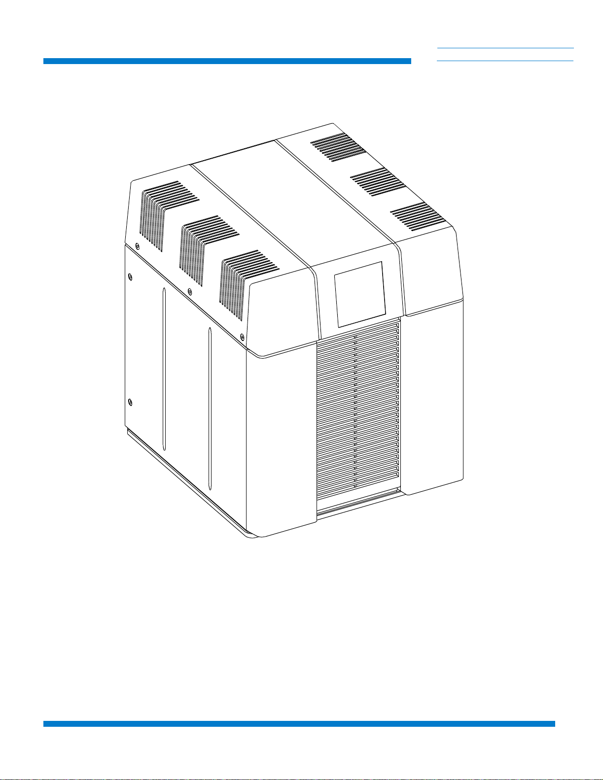
Figure 1-1: 9600 Compressor . . . . . . . . . . . . . . . . . . . . . . . . . . . . . . . . . . . . . . 1-3
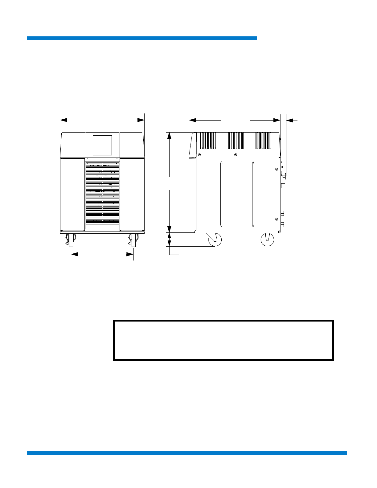
Figure 1-2: 9600 Compressor Dimensions . . . . . . . . . . . . . . . . . . . . . . . . . . . . 1-4
Figure 1 -3 : Wa t e r Fl o w Rate versu s Pressur e Dro p . . . . . . . . . . . . . . . . . . . . . 1-6
Figure 1-4: 9600 Compressor Rear View Component Locations . . . . . . . . . . . 1-8
Figure 1-5: 9600 Compressor Connected to Multiple On-Board Cryopumps . 1-12
Figure 1-6: 9600 Compressor Connected to Multiple Cryo-Torr Cryopumps 1-13
Figure 2 -1 : U si n g t h e Shi p p i n g C arton Ramp . . . . . . . . . . . . . . . . . . . . . . . . . . 2-2
Figure 3-1: 9600 Compressor Installation Flowchart . . . . . . . . . . . . . . . . . . . . 3-2
Figure 3-2: 9600 Compressor Circuit Breaker Terminals (Cover Removed) . . 3-5
Figure 3-3: Connecting/Disconnecting Helium Flex Line Self
Sealing Couplings . . . . . . . . . . . . . . . . . . . . . . . . . . . . . . . . . . . . . . 3-8
Figure 3-4: Single On-Board Cryopump Connections . . . . . . . . . . . . . . . . . . . 3- 9
Figure 3-5: Single Cryo-Torr Cryopump Installation . . . . . . . . . . . . . . . . . . . 3-10
Figure 3-6: Recommended Multiple On-Board Cryopump or
Waterpump Installation (Splitter Box located at Process Tool) . . 3-12
Figure 3-7: Alternative Multiple On-Board Cryopump or Waterpump Installation
(Splitter Box located at Compressor) . . . . . . . . . . . . . . . . . . . . . . . 3-13
Figure 3-8: Recommended Multiple Cryo-Torr Cryopump Installation . . . . . 3- 15
Figure 3-9: Alternative Multiple Cryo-Torr Cryopump Installation . . . . . . . . 3-16
P/N 8040540 6

9600 Compressor Installation, Operation, and Maintenance
Table of Contents (continued)
Figure 5-1: Disconnecting Self Sealing Couplings . . . . . . . . . . . . . . . . . . . . . . 5-2
Figure 5-2: Adsorber Location within the 9600 Compressor
(Rear Panel Rem o v e d ) . . . . . . . . . . . . . . . . . . . . . . . . . . . . . . . . . . . 5-3
Figure 5-3: 9600 Compressor Helium Pressure Control Components . . . . . . . 5-4
Figure B-1: 9600 Compressor Flow Diagram . . . . . . . . . . . . . . . . . . . . . . . . . . B-1
Figure D-1:9600 Motor Drive Compressor Schematic . . . . . . . . . . . . . . . . . . . D-2
Tables
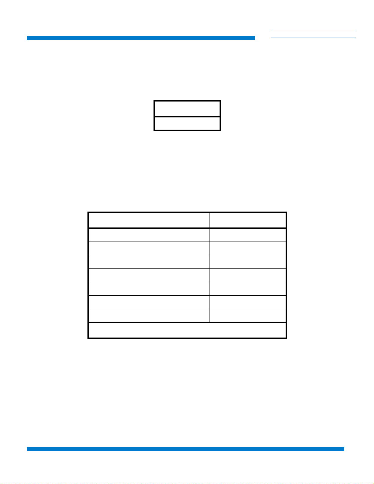
Table 1- 1 : Comp ressor Weight . . . . . . . . . . . . . . . . . . . . . . . . . . . . . . . . . . . . . 1-5
Table 1-2: Electrical Input Specifications . . . . . . . . . . . . . . . . . . . . . . . . . . . . . 1-5
Table 1- 3 : Cool ing Wate r Specifi c a t i o n s . . . . . . . . . . . . . . . . . . . . . . . . . . . . . . 1-6
Table 1- 4 : Gen eral Comp ressor O p erating Spe c i ficati o n s . . . . . . . . . . . . . . . . 1-7
Table 1-5: Cryopump Electrical Outlet Pin Assignments . . . . . . . . . . . . . . . . 1-10
Table 1-6: Compressor Remote Connector Pin Assignments . . . . . . . . . . . . . 1-11
Table 4-1: 9600 Compressor Helium Static Charge . . . . . . . . . . . . . . . . . . . . . 4-1
Table 5-1: Suggested Maintenance Equipment . . . . . . . . . . . . . . . . . . . . . . . . . 5-1
Table C-1: Compressor Troubleshooting Procedures . . . . . . . . . . . . . . . . . . . . C-2
7 P/N 8040540
9600 Compressor Installation, Operation, and Maintenance
Section 1 - 9600 Compressor Description
General
This manual provides the information required to install, operate, and
maintain the CTI-CRYOGENICS 9600 Compressor.
NOTE: All personnel with installation, operation, and maintenance
responsibilities should become familiar with the contents of both the 9600
Compressor Installation, Operation, Maintenance, and appropriate
cryopump manuals to ensure safe, high quality, and reliable system
performance.
Benefits
The 9600 Compressor is a universal compressor that accepts
three-phase 50Hz or 60 Hz power input and provides two-phase or threephase 60Hz power output to On-Board or Cryo-Torr Cryopumps.
-
TI CRYOG
C
HELIX TECHNOLOGY CORPORATION
EN
ICS
The 9600 Compressor design eliminates the use of three-phase motor
controllers and/or frequency converters and significantly reduces the
amount of equipment required and cost associated with the Cryopump
power circuit.
Refer to Appendix A to contact the local Customer Support Center for
information on connecting 9600 Compressors to a manifold with other
CTI-CRYOGENICS compressors.
Compressor Configurations
The 9600 Compressor supports either On-Board or Cryo-Torr Cryopumps.
For multiple cryopump installations, an On-Board Splitter Box or CryoTorr Interface can be used for cold head power distribution that reduces
total cable requirements as shown in Figure 1-5 and 1-6.
CAUTION
P/N 8040540 1-1

9600 Compressor Description
System Documentation
The manuals for a system cover two basic components: the cryopump and
the Compressor. A manual is shipped with each system component to
provide information for installation and operation of that component.
A loose-leaf binder with index tab separators is also provided so you can
compile a complete set of tabulated manuals.
CTI-CRYOGENICS Helium Refrigeration System
The operation of CTI-CRYOGENICS’ cryopumps is based upon a closed
loop helium expansion cycle. The system is made up of two major
components: the cryopump, which contains the cold head, and the helium
Compressor which compresses the helium gas.
Refrigeration is produced in the cryopump cold head through periodic
expansion of high pressure helium in a regenerative process. The high
pressure helium is provided by the Compressor. Low pressure helium
returning from the cold head is compressed into the necessary high
pressure to be returned to the cold head. The energy required to compress
the helium is rejected as heat through the cooling water.
-
TI CRYOG
C
HELIX TECHNOLOGY CORPORATION
EN
ICS
High pressure room temperature helium is transferred to the cold head
through the supply lines. After expansion, low pressure helium is returned
to the Compressor (at or near room temperature) to repeat the cycle in a
closed loop fashion. Large separation distances can be accommodated
between the Compressor and the cryopump.
In the Compressor, helium is compressed using a highly reliable oil
lubricated commercial Compressor. Helium purification takes place via
several stages of oil removal. The final stage of purification is performed
with a replaceable adsorber cartridge. In order to maintain peak efficiency,
the adsorber must be replaced every three years. The 9600 Compressor is
shown in Figure 1-1.
1-2 P/N 8040540
9600 Compressor Installation, Operation, and Maintenance
-
TI CRYOG
C
EN
ICS
HELIX TECHNOLOGY CORPORATION
0
0
6
R
9
O
S
S
0
R
E
0
O
6
R
S
9
P
S
M
E
O
R
C
P
M
O
C
Figure 1-1: 9600 Compressor
P/N 8040540 1-3
9600 Compressor Description
Specifications
Dimensions
TI CRYOG
C
HELIX TECHNOLOGY CORPORATION
The dimensions of the Compressor are shown in Figure 1-2.
-
EN
ICS
19.52 IN.
(496 MM)
14.4 IN.
(366 MM)
21.50 IN.
(546 MM)
23.36 IN.
(593 MM)
3.18 IN.
(81 MM)
Figure 1-2: 9600 Compressor Dimensions
1.28
(32MM)
CAUTION
Do not place a weight greater than 75 lbs. (34Kg) on top of the
Compressor.
1-4 P/N 8040540
9600 Compressor Installation, Operation, and Maintenance
Weight
The weight of the Compressor is listed in Table 1-1.
Table 1-1: Compressor W eight
Electrical
The electrical specificati ons of the Compre ss or are listed in
Table 1-2.
Weight
200lbs./91kg
-
TI CRYOG
C
HELIX TECHNOLOGY CORPORATION
EN
ICS
Table 1-2: Electrical Input Specifications
Parameter Value
Operating Voltage Range 180 - 253 VAC
Line Frequency 50/60 Hz
Phase 3
Nominal Input Power 5.5 KW Nominal Power Factor 0.85 Rated FL/LR* Current 16.2/80
Minimum Electrical Service 30 Amps
*FL/LR = Full Load/Locked Rotor
P/N 8040540 1-5
9600 Compressor Description
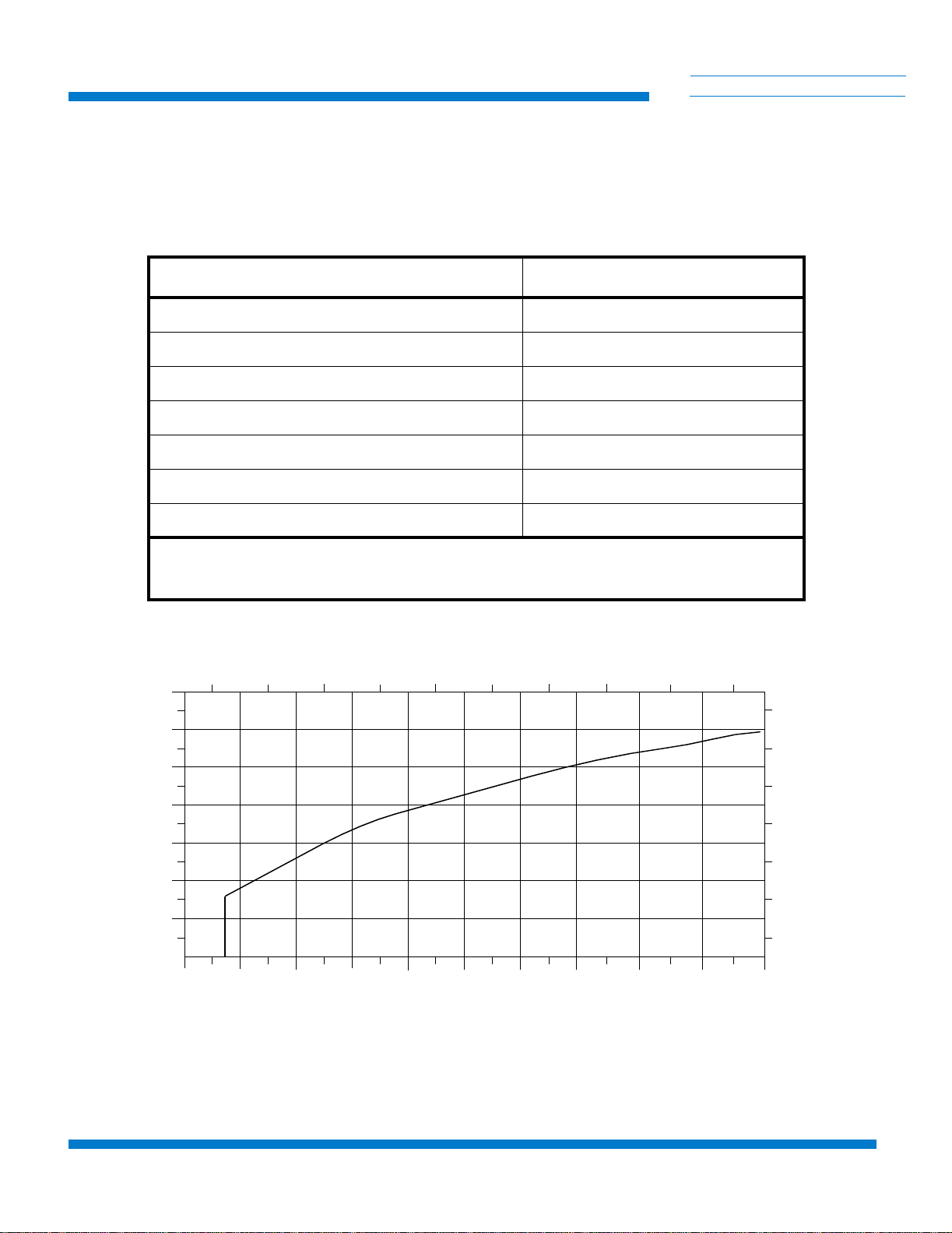
Cooling Water
Maximum Inlet Temperature 90°F (32°C) Minimum Inlet Temperature 50°F (10°C)
Pressure Drop (inlet-to-outlet) See Figure 1-3
Maximum Inlet Pressure 100 psi (6.9 bars)
-
TI CRYOG
C
HELIX TECHNOLOGY CORPORATION
The water used to cool the Compressor must meet the
specifications shown in Table 1-3 for proper system operation.
Table 1-3: Cooling W ater Specifications
Parameter Value
Flow Rate 2.75 ±1.25 gpm (10.4 ± 4.7 lpm)
Alkalinity 6.0 - 8.0 pH
EN
ICS
Calcium Carbonate < 75 ppm
NOTE: Water conditioning may be required for applications not meeting these
requirements.
WATER PRESSURE DROP (Bars)
.07 .49.21 .35 .63 .77
4.00
3.50
E
N
I
L
3.00
2.50
2.00
1.50
WATE R FLOW RATE (GPM)
E
P
O
E
L
B
A
T
P
E
C
C
A
G
N
I
T
A
R
1.00
0.50
1
3
5
WATER PRESSURE DROP (PSID)
7
911
15.2
13.3
11.40
9.50
7.60
5.70
3.80
1.90
WATER FLOW RATE (LPM)
NOTE: Figure 1-3 defines the wat er flow rate through the Compressor as a f unction of the pressure drop from water inlet to
water outlet. You must provide the correct pressure drop in your water supply system to ensure that the water fl ow condition
meets th e requirements specified in Table 1-3.
Figure 1-3: Water Flow Rate versus Pressure Drop
1-6 P/N 8040540

9600 Compressor Installation, Operation, and Maintenance
General
The information in Table 1-4 provides general Compressor operating
specifications.
Table 1-4: General Compressor Operating Specifications
Specification Values
Part Numbers
-
TI CRYOG
C
HELIX TECHNOLOGY CORPORATION
EN
ICS
Input Power Cable
(Customer Supplied)
Nominal Helium Pressure Refer to Table 4-1
Ambient Operating Temperature Range
Interface
Gas Supply Connector
Gas Return Connector
Remote Control Receptacle
600 VAC 10 Gauge, 3 conductor wire with ground Must conform to local electrical codes
50 - 100º F (10 - 38º C)
Cryopump Power Receptacles: mates with the
CTI-CRYOGENICS supplied cryopump power cable for
single pump use.
Mates with remote junction box power cable for multiple cryopump use.
1/2 in. Aeroquip self-sealing coupling
1/2 in. Aeroquip self-sealing coupling
24VAC, 2.7A inductive mates with P5 connector P/N MS3106A*
Adsorber Service Schedule 3 Years
* Supplied by CTI-CRYOGENICS
NOTE: The 9600 Compressor is designed for continuous operation and
should remain ON when the cryopumps are in a regeneration cycle.
P/N 8040540 1-7
9600 Compressor Description
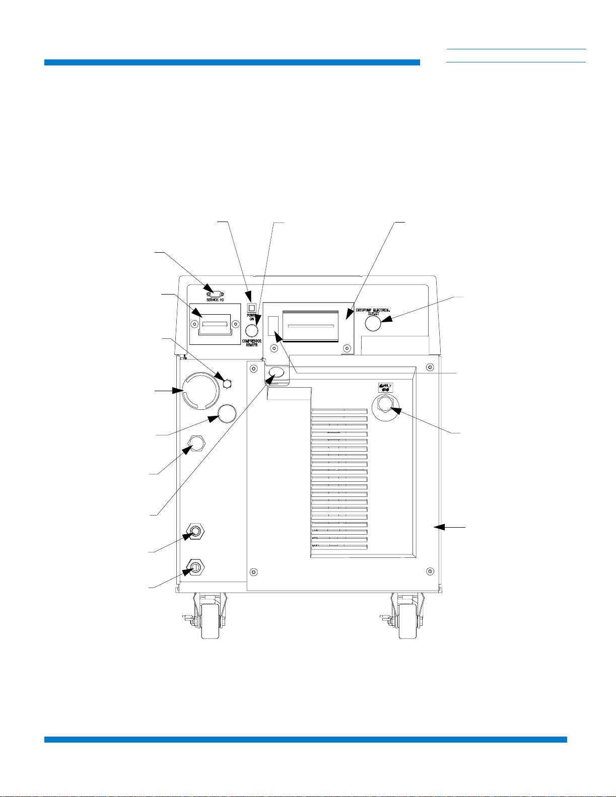
Component Description
-
TI CRYOG
C
HELIX TECHNOLOGY CORPORATION
The components of the 9600 Compressor that are accessible from the rear
panel are shown in Figure 1-4 and described in the following paragraphs.
EN
ICS
SERVICE I/O
CONNECTOR
CONTROL CIRCUIT
BREAKER
GAS CHARGE
FLARED FI TTING
HELIUM
PRESSURE
GAUGE
GAS CHARGE
CONTROL
VALVE
RETURN GAS
COUPLING
POWER ON
INDICATOR
COMPRESSOR REM O TE
CONNECTOR
SYSTEM CIRCUIT
BREAKER
CRYOPUMP
ELECTRICAL
OUTLET
CRYOPUMP
POWER PHASE
SWITCH
SUPPLY GAS
COUPLING
POWER
INLET
COOLING
WATER
IN
COOLING
WATER
OUT
REAR PANEL
Figure 1-4: 9600 Compressor Rear View Component Locations
1-8 P/N 8040540

9600 Compressor Installation, Operation, and Maintenance
System Circuit Breaker
The System Circuit Breaker protects main input power to the Compressor
pump and module. The circuit breaker positions are labeled ON (1), which
is in the UP position, and OFF (0), which is in the DOWN position.
NOTE: The phase monitor within the Compressor will cause the system
circuit breaker to open when input power phases are incorrect.
Control Circuit Breaker
The Control Circuit Breaker provides current overload protection for all
internal components of the Compressor except the Compressor motor. The
Compressor motor is protected by a separate overload protector. The
Control Circuit Breaker opens automatically and must be reset manually.
Power ON Indicator
The Power On Indicator illuminates when the system circui t breaker is
placed in the ON position. The Compressor pump is energized when the
power indicator is illuminated and the elapsed time meter records system
operation time.
-
TI CRYOG
C
HELIX TECHNOLOGY CORPORATION
EN
ICS
Gas Charge Flared Fitting
The Gas Charge Flared Fitting is used to connect a 99.999% pure helium
supply to the Compressor when helium charging is required. The fitting
has a 45º flare and 7/16 in. x 20 threads/inch.
Refer to Section 5 - Maintenance for information on adding helium to the
Compressor.
Helium Pressure Gauge
The Helium Pressure Gauge indicates system static helium charge pressure
when the Compressor and cryopumps are OFF and Compressor suction or
inlet pressure when the Compressor is ON. Refer to T a ble 4-1 for the
appropriate static helium charge pressure.
Power Inlet
The Power Inlet is used to connect your power cable to the Compressor.
Refer to Section 3 - Installation for information on power cable
installation.
P/N 8040540 1-9

9600 Compressor Description
Return Gas Coupling
Cooling Water IN
Cooling Water OUT
-
TI CRYOG
C
HELIX TECHNOLOGY CORPORATION
The Return Gas Coupling returns the helium, which has been cycled
through the cryopump, back to the Compressor. Refer to
CTI-CRYOGENICS Helium Refrigeration System within this section
for more information.
The Cooling Water IN connector provides water to the Compressor from
your facility to cool the Compressor during operation. The connector
thread size is a 1/2 in. female pipe thread. The water must meet the
specifications outlined in Table 1-3. Refer to Section 3 - Installation for
more information on cooling water connections.
The Cooling Water OUT connector returns the water that has been used to
cool the Compressor to your facility. The connector thread size is a
1/2 in. female pipe thread. Refer to Section 3 - Installation for more
information on cooling water connections.
EN
ICS
Cryopump Electrical Outlet
The Cryopump Electrical Outlet provide power to a single On-Board or
Cryo-Torr Cryopump, an On-Board Splitter Box, or a Cryo-Torr Interface.
The Compressor requires the use of an On-Board Splitter Box or
Cryo-Torr Interface for multiple cryopump system connections. Refer to
Table 1-5 for connector pin identification. Refer to Multiple On-Board
Cryopump Connections or Multiple Cryo-Torr Cryopump
Connections within this section for more information.
Table 1-5: Cryopump Electrical Outlet Pin Assignments
Identifier Function
A and B Heater Power - 208 VAC nominal
C Center tap for D and E
D and E 24 VCT @ 4.6 Amps
F-G and G-H Cold Head Voltage Output 130-160 VAC @ 4.5 Amps
J Chassis Ground
KNot Used
1-10 P/N 8040540

9600 Compressor Installation, Operation, and Maintenance
Cryopump Power Phase Sw itc h
NOTE: The Cryopump Power Phase Switch is behind the system circuit
breaker cover.
The Cryopump Power Phase Switch matches the output power phase of the
9600 compressor to that of the cryopump. The switch is set to the two or
three phase position based upon cryopump power requirements. Refer to
Section 3 - Installation for more information.
Compressor Remote Connector
The Compressor Remote Connector is a two-pin connector that can be us ed
in conjunction with the On-Board setpoint relays, relays in the Cryo-Torr
Interface, or a signal from the vacuum system to turn the Compressor ON
or OFF. Refer to Table 1-6 for connector pin identification. Switching
contacts must be rated at 24VDC, 2.7A inductive.
NOTE: The Compressor is shipped with a mating plug which must remain
installed in the Compressor Remote Connector to ensure Compressor
operation when the Compressor remote feature is not being used.
-
TI CRYOG
C
HELIX TECHNOLOGY CORPORATION
EN
ICS
Table 1-6: Compressor Remote Connector Pin Assignments
Identifier Function
A and B Compressor Remote Control - Make = ON, Break = OFF
Supply Gas Coupling
The Supply Gas Coupling provides a connection for high pressure
compressed helium to the cryopump cold head. Refer to
CTI-CRYOGENICS Helium Refrigeration System within this section
for more information.
Multiple On-Board Cryopump Connections
The On-Board Splitter Box permits the connection of multiple On-Board
Cryopumps or Waterpumps to one 9600 Compressor as shown in Figure
1-5. Refer to Section 3 - Installation for more information on connecting
single or multiple On-Board Cryopumps or Waterpumps to the
Compressor.
P/N 8040540 1-11

9600 Compressor Description
-
TI CRYOG
C
HELIX TECHNOLOGY CORPORATION
EN
ICS
HELIUM SUPPLY
WATER
REMOTE
POWER
HELIUM RETURN
ON-BOARD SPLITTER
BOX
ON-BOARD POWER
CABLE
Figure 1-5: 9600 Compressor Connected to Multiple On-Board Cryopumps
NOTE: Your installation (number of pumps per compressor) will vary
based upon the On-Board Cryopumps or W aterpumps used. Refer to
Appendix A to consult your local CTI-CRYOGENICS Customer Support
Center for information on specific compressor/pump applications.
1-12 P/N 8040540

9600 Compressor Installation, Operation, and Maintenance
Multiple Cryo-Torr Cryopump Connection s
The Cryo-Tor r Interface permits the connection of multiple
Cryo-Torr Cryopumps to one Compressor as shown in Figure 1-6.
Refer to Section 3 - Installation for more information on connecting
single or multiple Cryo-Torr Cryopumps to the Compressor.
-
TI CRYOG
C
HELIX TECHNOLOGY CORPORATION
EN
ICS
HELIUM SUPPLY
WATER
HELIUM RETURN
POWER
REMOTE
CRYO-TORR
CRYOPUMP POWER
CABLE
(FROM VACUUM SYSTEM)
Figure 1-6: 9600 Compressor Connected to Multiple Cryo-Torr Cryopumps
INTERFACE
USER REMOTE
NOTE: Your installation (number of pumps per compressor) will vary
based upon the Cryo-T orr Cryopump models used. Refer to Appendix A to
consult your local CTI-CRYOGENICS Customer Support Center for
information on specific compressor/cryopump applications.
P/N 8040540 1-13

9600 Compressor Description
-
TI CRYOG
C
HELIX TECHNOLOGY CORPORATION
EN
ICS
1-14 P/N 8040540

9600 Compressor Installation, Operation, and Maintenance
Section 2 - Unpacking and Inspection
Introduction
The 9600 Compressor is shipped in a shipping carton incorporating a ramp
system which makes removing the Compressor from the carton safe and
easy .
Shipping Carton Inspection
Inspect the exterior of the shipping carton for visible signs of damage
before opening the shipping carton. Report any damage to the shipping
company at once.
Removal from Shipping Carton
-
TI CRYOG
C
HELIX TECHNOLOGY CORPORATION
EN
ICS
1. Cut the two straps on the exterior of the shipping pallet.
2. Lift the cardboard carton straight up and remove it from the pallet.
3. Cut the tape which holds the ramp in the vertical position.
4. Swing the ramp down until the end touches the floor as shown in Figure 2-1.
5. Remove any excess shipping material from around the Compressor.
WARNING
Be certain to maintain control over the mov eme nt of the Compre ssor
as it rolls down the ramp. Injury to personnel may result if the
Compressor is allowed to roll freely down the ramp.
CAUTION
Be certain to maintain control over the mov eme nt of the Compre ssor
as it rolls down the ramp. Damage to the Compressor may
result if the Compressor is allowed to roll freely down the ramp.
6. Unlock the swivel casters as shown in Figure 2-1.
7. Carefully roll the Compressor down the ramp and onto the floor as shown in Figure 2-1.
P/N 8040540 2-1

Unpacking and Inspection
-
TI CRYOG
C
HELIX TECHNOLOGY CORPORATION
UNLOCK SWIVEL CASTERS
EN
ICS
Figure 2-1: Using the Shipping Carton Ramp
Comp ressor Inspe ction
Inspect the Compressor for visible signs of damage as indicated in the
following paragraphs.
Compressor
Inspect the exterior of the Compressor for visible signs of damage,
evidence of an oil leak, and check the Helium Pressure Gauge for proper
helium pressure. Report any damage to the shipping company at once.
Helium Static Pressure Verification
Refer to Section 4 - Operation for more information on the static helium
charge pressure of the 9600 Compressor.
Shipping Carton Contents
The shipping carton should contain the following items:
• Compressor
• Two barbed fittings for flexible water lines
• Installation, Operation, and Maintenance manual
• Compressor remote start connector and strain relief
2-2 P/N 8040540

9600 Compressor Installation, Operation, and Maintenance
Section 3 - Installation
Introduction
Section 3 provides you with the information required to install the
9600 Compressor and connect it to single or multiple On-Board or
Cryo-Torr Cryopump configurations.
Figure 3-1 highlights the major tasks for Compressor installation and
refers to the appropriate installation procedures within this section.
-
TI CRYOG
C
HELIX TECHNOLOGY CORPORATION
EN
ICS
P/N 8040540 3-1

Installation
START
Supply and Return Water Line Connections
(refer to page 3-3)
Electrical Connections
(refer to page 3-4)
Phase Check
(refer to page 3-6)
2Ø or 3Ø Cryopump
Power?
(refer to page 3-7)
-
TI CRYOG
C
HELIX TECHNOLOGY CORPORATION
EN
ICS
Connect/Disconnect Helium Flexlines
Sin gle Cryopump Connections
(refer to page 3-9)
(refer to page 3-7)
Single or Multiple
Cryopump
Installation?
Multiple Cryopump Connections
(refer to page 3-11)
Refer to
Section 4 - Operation
END
Figure 3-1: 9600 Compressor Installation Flowchart
3-2 P/N 8040540

9600 Compressor Installation, Operation, and Maintenance
Supply and Return W ater Line Connections
NOTE: The water used for cooling the Compressor must meet the
specifications outlined in Section 1 - Compressor Description.
Hard Water Lines
1. Apply a light coating of standard plumbing thread sealant to the hard line pipe threads.
2. Install the Supply hard line into the INPUT connection on the rear
panel of the Compressor. Tighten the fitting by hand.
3. Install the Return hard line into the OUTPUT connection on the
rear panel of the Compressor. Tighten the fitting by hand.
Do not overtighten the ferrules. Damage to the input and output
connector threads may occur.
CAUTION
-
TI CRYOG
C
HELIX TECHNOLOGY CORPORATION
EN
ICS
4. Using a wrench, tighten the fittings.
5. Allow water to flow and check for leaks at the rear of the Compressor.
Flexible Water Lines
1. Apply a light coating of standard plumbing thread sealant to the barbed fitting threads.
2. Install the barbed fittings into the INPUT and OUTPUT
connections on the rear panel of the Compressor.
Do not overtighten the barbed fittings. Damage to the INPUT and
OUTPUT connector threads may occur.
3. Using a wrench, tighten the barbed fittings.
4. Connect the Supply flexible water line to the INPUT barbed fitting and secure with a hose clamp.
5. Connect the Return flexible water line to the OUTPUT barbed fitting and secure with a hose clamp.
CAUTION
6. Allow water to flow and check for leaks at the rear of the Compressor.
P/N 8040540 3-3

Installation
Electrical Connections
Power Cable Preparation
-
TI CRYOG
C
HELIX TECHNOLOGY CORPORATION
The following procedures provide information for making all three phase
(180 - 250 VAC) electrical connections to the Compressor .
WARNING
Follow all local high voltage safety precautions when performing this
procedure to reduce the possibility of electrical shock. Make sure all
electrical power is OFF before proceeding with this procedure.
CAUTION
The cable used for making the Compressor power cable must be 10
gauge, 3 conductor cable with ground rated at 600 VA C .
EN
ICS
1. Cut a 10 AWG (6.00 mm2), 3 conductor cable with ground to an appropriate length.
2. Strip the cable jacket back 4 in. (101.6 mm).
3. Strip the insulation back 3/8 in. (9.3 mm) on each individual conductor.
4. Install a #10 ring tongue terminal on the end of each conductor
using the appropriate size double crimping tool.
5. Remove the rear panel as shown in Figure 3-2.
6. Remove the circuit breaker terminal cover as shown in Figure 3-2.
7. Install the cable into the Compressor through the cable strain relief.
8. Remove the 10-32 nut and install the grounding wire on the ground
stud. Install the nut and tighten to 18 in.-lbs (0.21m-kg).
NOTE: Use a slotted screw driver which is capable of holding a screw
when performing steps 9 and 10.
9. Remove the screws from the Compressor circuit breaker terminals
X, Y, and Z as shown in Figure 3-2.
3-4 P/N 8040540

9600 Compressor Installation, Operation, and Maintenance
-
TI CRYOG
C
HELIX TECHNOLOGY CORPORATION
EN
ICS
CRYOPUMP MOTOR
PHASE SWITCH
CIRCUIT BREAKER
TERMINAL COVER
(SEE DETAIL A)
REAR PANEL
CRYOPUMP
PHASE
2Ø
3Ø
THREE PHASE POWER
DETAIL A (COVER REMOVED)
X
Y
Figure 3-2: 9600 Compressor Circuit Breaker Terminals (Cover Removed)
NOTE: The phase order in which the conductor terminal lugs are
connected to circuit breaker terminals X, Y, and Z will be determined
during the Phase Check Procedure.
NOTE: For installation where one of the three phase legs is at or near
ground potential, connect that leg to terminal Y on the Compressor as
shown in Figure 3-2.
Z
10. Install the conductor terminal lugs to the circuit breaker terminals
X, Y, and Z as shown in Figure 3-2.
11. Torque the scre ws to 12 in.-lbs (0.14m-kg).
12. Allow enough cable to stay in the electrical enclosure to prevent
strain on the electrical connections and tighten the screws on the
cable strain relief.
13. Install the power source end of the power cable according to the local electrical codes.
14. Instal l the circuit breaker terminal cover.
15. Proceed with Phase Check.
P/N 8040540 3-5

Installation
Phase Check
-
TI CRYOG
C
HELIX TECHNOLOGY CORPORATION
WARNING
Follow all high voltage safety precautions when performing this
procedure to preven t the possibility of electrical shock.
1. Make sure power is applied to compressor circuit as described in Table 1-2.
NOTE: The cir cuit br eaker will trip immediately during step 2 if the power
phase connections are not correct.
2. Turn the Compressor circuit breaker to the ON position. If the
circuit breaker trips, refer to step 3. If the circuit breaker does not
trip, refer to step 4.
3. If the circuit breaker trips, perform the following steps: a. Turn the Compressor circuit breaker to the OFF position.
EN
ICS
b. Disconnect the power cord from the power source.
c. Remove the circuit breaker terminal cover.
d. Reverse the wiring order of Compressor circuit breaker
terminals X and Y.
e. Torque the circuit brea ke r termina l scr ews to 12 in.-lbs.
f. Install the circuit breaker terminal cover.
g. Repeat steps 1- 2 of this procedure.
4. Install the rear panel.
5. Proceed with Cryopump Power Phase Sw itc h Se tting.
3-6 P/N 8040540

9600 Compressor Installation, Operation, and Maintenance
Cryopump Power Phase Switch Setting
NOTE: On-Boar d Cryopumps can operate on two or three-phase power.
Cryo-Torr Cryopumps only operate on two-phase power.
1. Inspect the On-Board Cryopump(s) being installed for the
presence of a THREE-PHASE label by the RETURN helium
connector.
2. If a three-phase label is present, set the cryopump power phase
switch, shown in Figure 3-2, to the 3PH position.
3. If a three-phase label is not present, or Cryo-Torr Cryopumps are
being installed, set the cryopump power phase switch, shown in
Figure 3-2, to the 2PH position.
NOTE: All Cryopumps being connected to the 9600 Compressor must
operate at the same phase.
Connecting/Disconnecting Helium Flex Lines
-
TI CRYOG
C
HELIX TECHNOLOGY CORPORATION
EN
ICS
Connecting
CAUTION
Make sure the helium flex lines are connected and disconnected from
the 9600 Compressor using the following procedure and as shown in
Figure 3-3. Failure to follow this procedure could damage connector
O-ring seals or cause a helium circuit leak.
1. Remove all dust plugs and caps from the Gas Supply and
Return lines, and the Compressor and cryopump Supply and
Return connectors. Check for the presence of a flat gasket in
the male connector, and no gasket in the female connector.
2. Connect the Gas Return line to the GAS RETURN connector on the
rear of the Compressor and then to the GAS RETURN connector
on the cryopump. Using two wrenches as shown in Figure 3-3,
tighten the connector.
3. Connect the Gas Supply line to the GAS SUPPLY connector on the
rear of the Compressor and then to the GAS SUPPLY connector on
the cryopump. Using two wrenches as shown in Figure 3-3, tighten
the connector.
4. Attach the Supply and Return line identification labels to each end of the appropriate lines.
P/N 8040540 3-7

Installation
Disconnecting
-
TI CRYOG
C
HELIX TECHNOLOGY CORPORATION
1. Using two wrenches as shown in Figure 3-3, disconnect the two
self sealing coupling connectors quickly to minimize helium
leakage.
To Tighten Coupling Halves
Turn Here
Hold Here
EN
ICS
This 1 1/8 in. wrench
holds the coupling in a
stationary position.
This 1 3/16 in. wrench
is used to turn the self
sealing coupling
connector.
Hold Here
To Loosen Coupling Halves
Turn Here
Side View
Figure 3-3: Connecting/Disconnecting Helium Flex Line Self Sealing Couplings
3-8 P/N 8040540

9600 Compressor Installation, Operation, and Maintenance
Single On-B oar d Cr yopu mp Connecti ons
Make sure the Compressor power is OFF before making any
connections to the rear panel.
1. Connect the Supply and Return lines to the 9600 Compressor as
described in Connecting/Disconnecting Helium Flex Lines
within this section.
2. Connect one end of the Cryopump cold head cable to the
CRYO PU MP ELECTRIC A L O U TLET on the rear p a n el of t h e
Compressor as shown in Figure 3-4.
3. Connect the opposite end of the cold head cable to the cryopump cold head cable connector.
CAUTION
-
TI CRYOG
C
HELIX TECHNOLOGY CORPORATION
EN
ICS
HELIUM SUPPLY
WATER
REMOTE
POWER
HELIUM RETURN
ON-BOARD
POWER CABLE
Figure 3-4: Single On- Board Cryopump Connections
P/N 8040540 3-9

Installation
Single Cryo-Torr Cryopump Connections
Make sure the Compressor power is OFF before making any
connections to the rear panel.
1. Connect the Supply and Return lines to the 9600 Compressor as
described in Connecting/Disconnecting Helium Flex Lines
within this section.
2. Connect one end of the Cryopump cold head cable to the
CRYO PU MP ELECTRIC A L O U TLET on the rear p a n el of t h e
Compressor as shown in Figure 3-5. Connect the opposite end of
the cold head cable to the cryopump cold head cable connector as
shown in Figure 3-5.
CAUTION
-
TI CRYOG
C
HELIX TECHNOLOGY CORPORATION
EN
ICS
HELIUM SUPPLY
WATER
REMOTE
POWER
HELIUM RETURN
CRYO-TORR
POWER CABLE
Figure 3-5: Single Cryo-Torr Cryopump Installation
3-10 P/N 8040540

9600 Compressor Installation, Operation, and Maintenance
Multiple On-Board Cryopump Connections
Make sure the Compressor power is OFF before making any
connections to the rear panel.
Helium Line Connections
The use of several compressors on a single manifold feeding a common
supply header and a common return header requires special
precautions. Contact CTI-CRYOGENICS for a review of the intended
installation and for specific technical instructions. The use of a 9600
compressor on a manifold with other CTI-CR YOGENICS compressor
models requires a reduction of the helium charge pressure to 200 - 210
psig charge pressure to av oid he lium safety valves from inadvertently
venting. Refer to Section 4 - Operat ion and Section 5 - Mainte nance
for more information.
CAUTION
CAUTION
-
TI CRYOG
C
HELIX TECHNOLOGY CORPORATION
EN
ICS
1. Connect the Supply and Return lines to the 9600 Compressor as
described in Connecting/Disconnecting Helium Flex Lines
within this section.
2. Connect the Gas Return Line to the customer supplied helium
manifold and then to the GAS RETURN connector on the
On-Board Cryopump.
3. Connect the Gas Supply Line to the customer supplied helium
manifold and then to the GAS SUPPLY connector on the On-Board
Cryopump.
P/N 8040540 3-11

Installation
Power Cable Connections
1. Connect the On-Board Splitter Box power cable between the
CRYOPUMP ELECTRICAL OUTLET on the rear panel of the
Compressor and the On-Board Splitter Box power connector as
shown in Figure 3-6.
2. Connect the On-Board Cryopump or Waterpump power cables to
the CRYOPUMP 1, 2, or 3 connectors on the On-Board Splitter
Box and the respective cryopumps as shown in Figure 3-6.
NOTE: Your installation (number of pumps per compressor) will vary
based upon the On-Board Cryopump models used. Refer to Appendix A to
consult your local CTI-CRYOGENICS Customer Support Center for
information on specific compressor/pump applications.
NOTE: The On-Board Splitter Box can be installed at the process tool
containing the pumps as shown in Figure 3-6, or on the rear of the
Compressor as shown in F igur e 3-7. CTI-CRY OGENICS recommends that
the On-Board Split ter box be ins talled near the pr ocess t ool to re duce cable
requirements.
-
TI CRYOG
C
HELIX TECHNOLOGY CORPORATION
EN
ICS
HELIUM SUPPLY
WATER
REMOTE
POWER
HELIUM RETURN
ON-BOARD POWER CABLE
ON-BOARD SPLITTER
BOX
Figure 3-6: Recomme nde d Multiple On-Board Cryopum p or Waterpump Installation
(Splitter Box located at Process Tool)
3-12 P/N 8040540

9600 Compressor Installation, Operation, and Maintenance
-
TI CRYOG
C
HELIX TECHNOLOGY CORPORATION
EN
ICS
HELIUM SUPPLY
WATER
REMOTE
POWER
HELIUM RETURN
ON-BOARD
SPLITTER
BOX
ON-BOARD POWER CABLES
Figure 3-7: Alter native Multiple On-Board Cryop ump or Waterpump Installation
(Splitter Box located at Compressor)
Multiple Cryo-Torr Cryopump Connections
Make sure the Compressor power is OFF before making any
connections to the rear panel.
Helium Line Connections
The use of several compressors on a single manifold feeding a common
supply header and a common return header requires special
precautions. Contact CTI-CRYOGENICS for a review of the intended
installation and for specific technical instructions.
The use of a 9600 compressor on a manifold with other
CTI-CRYOGENICS compressor models requires a reduction of the
helium charge pressure to 200 - 210 psig charge pressure to avoid
helium safety valv e s from inadv e rte ntly venting. Refer to Section 4 -
Operation and Section 5 - Maintenance for more i nform ation.
CAUTION
CAUTION
P/N 8040540 3-13

Installation
1. Connect the Supply and Return lines to the 9600 Compressor as
described in Connecting/Disconnecting Helium Flex Lines
within this section.
2. Connect the Gas Return Line to the customer supplied helium
manifold and then to the Gas Return connector on the Cryo-Torr
Cryopump.
3. Connect the Gas Supply Line to the customer supplied helium
manifold and then to the Gas Supply connector on the Cryo-Torr
Cryopump.
Power Cable Connections
1. Connect the Cryo-Torr power cable between the CR YOPUMP
ELECTRICAL OUTLET on the rear panel of the Compressor
and the CR YOPUMP ELECTRICAL INPUT on the Cryo-Torr
Interface as shown in Figures 3-8 or 3-9.
2. Connect the Cryo-Tor r Po wer Cables between the CRYOPUMP 1,
2, or 3 connectors on the Cryo-To rr Interface and the respective
Cryo-Torr Cryopumps as shown in Figures 3-8 or 3-9.
-
TI CRYOG
C
HELIX TECHNOLOGY CORPORATION
EN
ICS
3. Connect the User Remote cable to the Cryo-T orr Interface as shown in Figures 3-8 or 3-9.
4. Connect the Remote cable between the Cryo-Torr Interface and the
Compressor as shown in Figures 3-8 or 3-9.
NOTE: Your installation may vary based upon the Cryo-Torr Cryopump
models used. Refer to Appendix A to consult your local
CTI-CRYOGENICS Customer Support Center for information on specific
compressor/cryopump applications.
3-14 P/N 8040540

9600 Compressor Installation, Operation, and Maintenance
NOTE: The Cryo-Torr Interface can be installed at the process tool
containing the cryopumps as shown in Figure 3-8 or near the Compressor
as shown in Figure 3-9. CTI-CRYOGENICS recommends that the CryoTorr Interface be installed at the process tool to reduce cable requirements.
-
TI CRYOG
C
HELIX TECHNOLOGY CORPORATION
EN
ICS
HELIUM SUPPLY
WATER
HELIUM RETURN
REMOTE
CRYO-TORR
INTERFACE
POWER
CRYOPUMP POWER CABLE
USER REMOTE
(FROM VACUUM SYSTEM)
Figure 3-8: Recommended Multiple Cryo-Torr Cryopump Installation
P/N 8040540 3-15

Installation
-
TI CRYOG
C
HELIX TECHNOLOGY CORPORATION
EN
ICS
HELIUM SUPPLY
WATER
HELIUM RETURN
REMOTE
CRYO-TORR
INTERFACE
CRYOPUMP POWER CABLES
POWER
USER REMOTE
(FROM VACUUM SYSTEM)
Figure 3-9: Alternative Multiple Cryo-Torr Cryopump Installation
3-16 P/N 8040540

9600 Compressor Installation, Operation, and Maintenance
Section 4 - Operation
Adjusti ng System Helium Pressure
Your CTI-CRYOGENICS high vacuum pump system is comprised of
several pressurized components i.e. compressor , flex lines, and cryopumps.
Each component is charged with helium before shipment. After all
cryopumps, helium lines, and manifolds are attached to the compressor , the
system static helium charge pressure must be verified before system
operation. Once the static helium system pressure has been verified, the
system is ready for operation. After cooldown, the normal system
operating pressure is recorded .
NOTE: The 9600 Compressor is designed for continuous operation and
should remain ON even when the cryopumps are in a regeneration cycle.
-
TI CRYOG
C
HELIX TECHNOLOGY CORPORATION
EN
ICS
Static Helium System Pressure Verification
The proper system static helium charge pressure is necessary so that the
cryopumps operate at maximum performance as well as to assure that the
compressor will operate below the maximum design motor winding
temperature which will maximize the life of the compressor motor.
1. Make sure the Compressor and Cryopump(s) are OFF.
2. Make sure all system components are connected together as described in Section 3 - Installation.
3. Allow all system components to acclimate to a temperature
between 60º F and 80º F (15.5º C - 26.6º C).
4. Read the compressor helium pressure gauge located on the compressor rear panel as shown in Figure 1-4. Compare the gauge
reading to the appropriate 50/60 Hz line frequency value (depending upon your system installation) indicated in Table 4-1.
Table 4-1: 9600 Compressor Helium Static Charge
Line Frequency Helium Static Charge Pressure
60 Hz 240 - 250 psig (16.5 - 17.2 bars ) 50 Hz 255 - 265 psig ( 17.6 -18.3 bars )
P/N 8040540 4-1

Operation
Compressor Operation
-
TI CRYOG
C
HELIX TECHNOLOGY CORPORATION
NOTE: The use of a higher helium charge pressure for 50 HZ operation is
necessary in order to compensate for the slower speed at which the
compressor operates at 50 HZ. The static charg e level for 60 Hz re mains
at 240-250 PSIG.
CAUTION
Exceeding the recommended system static helium charge pre s sure will
result in the compressor and cryopump safety relief valves opening and
releasing excess helium gas.
5. If the static helium charge pressure is not within the ranges as indicated in T able 4-1, then adjust the charge pressure as described in
Section 5- Maintenance.
The system may be operated once the helium charge pressure is correct.
Perform the following steps to start the compres sor:
EN
ICS
1. Set the System Circuit Breaker to the ON (UP) position.
2. Set the Control Circuit Breaker to the ON (UP) position.
3. Close all Cryopump gate valves.
4. Refer to the On-Board Module Pr ogramming and Operation
manual or Cryo-Torr Cryopump Installation and Service man-
ual (that came with your cryopump) and perform the cryopump
start-up procedure.
5. Once the second stage temperature for all cryopumps is below 17K,
record the compressor pressure gauge reading as the normal system
operating pressure.
NOTE: During compressor operation, the compressor gauge reads the
pressure of the gas entering the compressor prior to it being compressed.
6. Affix a copy of the data next to the compressor gauge on each compressor . This data is to be verified for each tool installation and
whenever a configuration change is made affecting the amount of
system helium gas and line volume.
The compressor pressure reading will decrease from the normal system
operating pressure during cryopump regeneration or if fewer cryopumps
are being operated. These are normal variations in the compressor pressure
reading and should not be cause for concern.
4-2 P/N 8040540

9600 Compressor Installation, Operation, and Maintenance
If you have concerns about system performance changing, then check the
normal system operating pressure which was determined in Compressor
Operation within this section. If the normal system operating pressure is
not correct, check the system for leaks.
Once the leaks have been repaired, helium must be added to return the
system to normal operating system pressure as described in
Section 5- Maintenance.
Repl acement of He lium Circuit C o mponents
On occasion, it may be necessary to replace components such as
cryopumps, helium gas lines or compressors, or change the configuration
of the system. Whenever any of these conditions occur, Static Helium
System Pressure Verification should be performed to ensure that static
helium pressure has not changed.
-
TI CRYOG
C
HELIX TECHNOLOGY CORPORATION
EN
ICS
CAUTION
The use of several compressors on a single manifold feeding a common
supply header and a common return header requires special
precautions. Contact CTI-CRYOGENICS for a review of the intended
installation and for specific technical instructions.
The use of a 9600 compressor on a manifold with other
CTI-CRYOGENICS compressor models requires a reduction of the
helium charge pressure to 200--210 psig charge pressure to avoid
helium safety valve s from inadv e rte ntly venting.
P/N 8040540 4-3

Operation
-
TI CRYOG
C
HELIX TECHNOLOGY CORPORATION
EN
ICS
4-4 P/N 8040540

9600 Compressor Installation, Operation, and Maintenance
Section 5 - Maintenance
Sche duled Maintenance
Suggested Maintena nc e Equipment
It is recommended to have the following equipment and disposable
supplies available as listed in Table 5-1.
Table 5-1: Suggested Mai nte nanc e Equi pment
Supply CTI-CRYOGENICS P/N
Helium, 99.999% pure -
-
TI CRYOG
C
HELIX TECHNOLOGY CORPORATION
EN
ICS
Pressure regulator (0-3000/0-400 psi) Assy . 8031403
Helium charging line terminating in a 1/4-inch
female flare fitting
Lint-free gloves and cloth -
Oakite or equivalent detergent soap -
Denatured alcohol -
Refer to Appendix A and contact the local Customer Support Center to obtain the
CTI-CRYOGE NICS parts listed in this table.
7021002P001
P/N 8040540 5-1

Maintenance
Adsorber Replacement
Use the following procedure to change the adsorber every three years.
1. Set the System Circuit Breaker, on the rear of the 9600 Compressor, to the OFF position.
2. Remove the 4 screws which secure the rear panel to the Compressor and remove the rear panel.
NOTE: Use two wrenches in Step 3 to prevent loosening the body of the
coupling.
3. Using a 1-3/16 in. wrench, and a 1-1/8 in. wrench, as shown in Figure 5-1, disconnect the two self sealing coupling connectors quickly
to minimize helium leakage.
-
TI CRYOG
C
HELIX TECHNOLOGY CORPORATION
To Tighten Coupling Halves
Turn Here
Hold Here
EN
ICS
This 1 1/8 in. wrench
holds the coupling in a
stationary position.
This 1 3/16 in. wrench
is used to turn the self
sealing coupling
connector.
Hold Here
To Loosen Coupling Halves
Turn Here
Side View
Figure 5-1: Disconnecting Self Sealing Couplings
4. Using a 7/16 in. (11mm) wrench, remove the adsorber mounting bolt as shown in Figure 5-2.
5. Move the adsorber from under the mounting tabs in the base as
shown in Figure 5-2 and remove the adsorber from the Compressor.
6. Install the replacement adsorber under the mounting tabs and
secure it into place with the bolt removed during Step 4.
7. Using two wrenches as shown in Figure 5-1, connect the two self
sealing couplings quickly to minimize helium leakage.
8. Install the Compressor rear panel.
5-2 P/N 8040540

9600 Compressor Installation, Operation, and Maintenance
9. Ensure that the pressure gauge reads the proper value as shown in
Table 4-1. If additional gas pressure is required, refer to Adding
Helium within this section. If gas pressure needs to be reduced,
refer to Reducing Helium Pressure within this section.
10. Record the adsorber replacement date on the label as shown in Figure 5-2, and also note that the next adsorber replacement should be
performed every three years.
-
TI CRYOG
C
HELIX TECHNOLOGY CORPORATION
EN
ICS
DATE
ADSORBER
ADSORBER
MOUNTING
BOLT
Figure 5-2: Adsorber Location within the 9600 Compressor (Rear Panel Removed)
P/N 8040540 5-3

Maintenance
Adjusti ng System Helium Pressure
NOTE: Thes e pr ocedur es can be performed on a compressor that is turned
ON or OFF. However, the helium pressur e gaug e should be set to the static
helium char ge pressur e value if the compressor is turned OFF or set to the
normal system operating pres sur e if the compr essor is turned ON. Refer to
Section 4 - Operation for more information.
Reducing Helium Pressure
NOTE: You must obtain the normal system operating pressure from the
Compressor Operation procedure in Section 4 - Operation in order to
perform this procedur e. If the normal system operating pressur e is
unknown, then shut the compressor OFF and perform the Static Helium
System Pressur e Verifica t ion procedure in Section 4 - Operation instead.
1. Remove the flare cap from the gas charge f itting as show n in Figure 5-3.
-
TI CRYOG
C
HELIX TECHNOLOGY CORPORATION
EN
ICS
GAS CHARGE FLARED FITTING
HELIUM PRESSURE
GAUGE
GAS CHARGE
CONTROL VALVE
REAR PANEL
Figure 5-3: 9600 Compressor Helium Pressure Control Components
2. Open the gas charge control valve very slowly to allow a slight
amount of helium to escape. Leave the valve open until the helium
pressure gauge indicates one of the following:
• To the appropriate value in T a ble 4-1 if the compressor is OFF and
acclimated to a temperature between 60º F and 80º F
(15.5º C - 26.6º C).
5-4 P/N 8040540

9600 Compressor Installation, Operation, and Maintenance
• To the value pre viously recorde d in the Compressor Operation
procedure in Section 4 - Operation if the compressor is ON.
3. Close the gas charge control valve and install the flare cap.
Increasing He lium Pressure
Use the following procedure to increase the helium pressure if the
indicated pressure is below the appropriate value as shown in Table 4-1.
If helium is being added more than once every several months, check
for leaks caused by improperly connected self-sealing connections or
any mechanical joint within the Compressor.
CAUTION
-
TI CRYOG
C
HELIX TECHNOLOGY CORPORATION
EN
ICS
Adding Helium
NOTE: You must obtain the normal system operating pressure from the
Compressor Operation procedure in Section 4 - Operation in order to
perform this procedur e. If the normal system operating pressur e is
unknown, then shut the compressor OFF and perform the Static Helium
System Pressur e Verifica t ion procedure in Section 4 - Operation instead.
This procedure ensures that both the regulator and the charging line will be
purged of air and that the air trapped in the regulator will not diffuse back
into the helium bottle. For best results, CTI-CRYOGENICS suggests a
dedicated helium bottle, regulator, and line, which are never separated, for
adding helium.
NOTE: You are required to supply the helium charging line terminating in
a 1/4-inch female flare fitting, and a two-stage pressur e r egulator rated at
0-3000/0-400 psig for this operation.
Use only 99.999% pure helium gas. Helium circuit contamination may
result if a lower quality of helium is used.
CAUTION
1. Attach a regulator (0-3000/0-400 psig) and charging line to a helium bottle (99.999% pure).
NOTE: Do not open the bottle at this time.
P/N 8040540 5-5

Maintenance
-
TI CRYOG
C
HELIX TECHNOLOGY CORPORATION
2. Purge the regulator and charging lines as follows: a. Open the regulator a small amount by turning the adjusting
knob clockwise until it contacts the diaphragm, then turn
approximately 1/8 to 1/4 turn more, so that the regulator is
barely open.
b. Loosely connect the charge line to the helium pressure
regulator.
c. Slowly open the bottle valve, and purge the regulator and
line for 10 to 15 seconds. Turn the regulator knob
counterclockwise until the helium stops flowing.
3. Remove the flare cap of the gas charge flared fitting on the rear of the Compressor .
4. Loosely connect the charging line from the helium pressure regulator to the 1/4-inch male flare fitting installed on the helium charge
valve. Purge the charge line again, as in step a, for 30 seconds, and
tighten the charge line flare fitting onto the gas charge fitting while
the helium is flowing.
EN
ICS
5. Set the helium pressure regulator to 300 psig (20.7 bars). If the
compressor is ON, proceed with step a. If the compressor is OFF,
proceed with step b.
a. Obtain the previously recorded normal system operating
pressure from the Compressor Operation procedure in
Section 4 - Operation. Open the gas charge control valve
very slowly and allow helium to flow until the compressor
gauge reading is the same as the value obtained from
Section 4. Quickly close the gas charge control valve.
b. Obtain the appropriate (50 or 60 Hz) static system oper ating
pressure from Table 4-1. Open the gas charge control valve
very slowly and allow helium to flow until the compressor
gauge reading is the same as the appropriate value in T able
4-1. Quickly close the gas charge control valve.
6. Ensure that the helium charge valv e on the Compressor is tightly
closed. Shut off the helium pressure re gulator on the helium bottle
and remove the charging line from the male flare fitting. Reinstall
the flare cap.
5-6 P/N 8040540

Prelimary
Document Title
Appendix A - Customer Support Information
Customer Support Center Locations
To locate a Customer Support Center near you, please visit our website
www.helixtechnology.com on the world wide web and select CONTACT on
the home page.
Guaranteed Up-Time Support (GUTS®)
For 24-hour, 7-day per week Guaranteed Up-Time Support (GUTS) dial:
1 800-367-4887 - Inside the United States of America
ELIXH
+1 508-337-5599 - Outside the United States of America
Product Information
Please have the following information available when calling so that we
may assist you:
• Product Part Number
• Product Serial Number
• Product Application
• Specific Problem Area
• Hours of Operation
• Equipment Type
• Va cuum System Brand/Model/Date of Manufacture
For your convenience, you may also e-mail us at:
techsupport@helixtechnology.com
©2004 Helix Technology Corporation Pub. No. 8040509, Rev. 101, 01/26/04 ECO No. 16210 A-1


9600 Compressor Installation, Operation, and Maintenance
Appendix B - Flow Diagram
-
TI CRYOG
C
HELIX TECHNOLOGY CORPORATION
EN
ICS
Figure B-1:9600 Compressor Flow Diagram
P/N 8040540 B-1

Appendix B - Flow Diagram
B-2 P/N 8040540

9600 Compressor Installation, Operation, and Maintenance
Appendix C - Troubleshooting Procedures
Troubleshooting the Compressor
The compressor troubleshooting procedures are summarized in Table C-1.
Te c hn i ca l I nquiries
Please refer t o Appendix A of this manual for a complete list of the
CTI-CRYOGENICS’ world wide customer support centers.
Disconnect the compressor before performing any troubleshooting procedures.
WARNING
-
TI CRYOG
C
HELIX TECHNOLOGY CORPORATION
EN
ICS
The compressor pump is hot after operating. Wait for the pump to cool
down before working on the inside of the compressor
Do not change or modify any compressor internal wiring circuits, this
may cause failure of the compressor and cold head due to improper phasing.
P/N 8040540 C-1

Appendix C - Troubleshooting Procedures
Table C-1: Compressor Tr oubleshooting Procedures
Problem Possible Cause Corrective Action
-
TI CRYOG
C
HELIX TECHNOLOGY CORPORATION
EN
ICS
1) System circuit breaker
(CB1) trips immediately
to the OFF (0) position
when switched to the ON
(1) position.
2) System (CB1) and Control Circu it (C B 2) c irc u it
breakers remain in the
ON (1) position when
switched ON but the
compressor will not run.
1) Incorrect phasing of input
power.
1) No power coming from
source.
2) Insufficient power
3) Remote control jumper
plug not in place. This will
apply only if remote circuit is not being used.
1) Check phasing of input
power. Refer to Phase
Check in Section 3.
1) Check source fuses, circuit breakers, and wiring
associated with the
power source. Repair as
needed.
2) Verify adequate phase-tophase input voltage.
Refer to Table 1-2.
3) Check to insure that
remote jumper plug is
fully seated. See Figure
1-4 for location. Refer to
Compressor Remote
Connector in Section 1
for mo re i nform a t ion.
4) Improperly wired external
remote control circuit.
NOTE: Only applies if
remote control feature is
being used.
C-2 P/N 8040540
4) Verify correct installation
of remote control feature.
Refer to Table 1-6.

9600 Compressor Installation, Operation, and Maintenance
Table C-1: Compressor Troubleshooting Procedures (Continued)
Problem Possible Cause Corrective Action
-
TI CRYOG
C
HELIX TECHNOLOGY CORPORATION
EN
ICS
3) System circuit breaker
(CB1) will not remain in
the ON (1) position
when switched ON. The
Control Circuit circuit
breaker (CB2) trips
when excessive current
is being drawn by the
cold head or 24 volt
compressor control circuits.
4) System circuit breaker
(CB1) remains in the ON
(1) position and the compressor stops after several minutes of operation
and remains OFF (0).
1) Damaged On-Board
power cable, connectors,
or drive motor.
2) Damaged component in
the compressor power or
control circuit.
1) Thermal protective
switches are open.
2) Very cold water has caused
a restriction of oil flow
through the oil injection
orifice during start-up.
1) Check for compressor
operation with cryopump
cable disconnected from
compresso r. Refer to
Appendix A to contact
the Customer Support
Center if the compressor
operates improperly.
2) Refer to Appe ndix A to
contact the Customer
Support Center.
1) Check for inadequate
water c o olin g . R e fer to
Table 1-3.
2) Recheck for proper cool-
ing water temperature.
Refer to Table 1- 3.
Restart compressor
repeatedly until continuous operation is achieved.
5) System circuit breaker
(CB1) trips after a pe riod
of running.
6) All cryopumps making
loud noise.
P/N 8040540 C-3
1) Loss or degradation of
power from the source.
2) Defective motor windings.
1) Cryopump power phase
switch is in the wrong
position.
1) Check that line voltage is
correct on all phases.
2) Check running current on
all phases.
3) Refer to Appe ndix A to
contact the local Customer Support Center.
1) Set power phase switch in
opposite position.

Appendix C - Troubleshooting Procedures
-
TI CRYOG
C
HELIX TECHNOLOGY CORPORATION
EN
ICS
C-4 P/N 8040540

9600 Compressor Installation, Operation, and Maintenance
Appendix D - Schematic
-
TI CRYOG
C
HELIX TECHNOLOGY CORPORATION
EN
ICS
P/N 8040540 D-1

Figure D-1:9600 Motor Drive Compressor Schematic
 Loading...