

Page 1
TITLE
Service Manual
LCD TV For 237-T11
Doc No. SM_237-T11_19Nov07
Version 1.2
Page
Page
PagePage
1/72
Service Manual
LCD TV For 237-T11
Model Number: 237T Model Name:237-T11 FM Number.::::FM1
Model Number: 237T Model Name:237-T11 FM Number.::::FM1
Model Number: 237T Model Name:237-T11 FM Number.::::FM1
FM1----037000EGS25
037000EGS25
FM1FM1
037000EGS25037000EGS25
FM1----037000EGS36
037000EGS36
FM1FM1
037000EGS36037000EGS36
FM1----03700DEGS46
03700DEGS46
FM1FM1
03700DEGS4603700DEGS46
Approval Made by
Company Confidential-DRAFT
Page 2

TITLE
Service Manual
LCD TV For 237-T11
Hans Chung
2007/11/19
Doc No. SM_237-T11_19Nov07
Version 1.2
Page 2/72
Jill kao
2007/11/19
Company Confidential-DRAFT
Page 3
Doc No. SM_237-T11_19Nov07
Version 1.2
Page 3/72
TITLE
Service Manual
LCD TV For 237-T11
Document change / update record
Update date Version Page Update record
2007/07/03 V1.1
2007/11/19 V1.2
Updated Parts list(LPL WX4-SLA1)
Updated Parts list(LPL WX1-SL01 /LPLWX1-SLA1)
Company Confidential-DRAFT
Page 4
Doc No. SM_237-T11_19Nov07
Version 1.2
Page 4/72
TITLE
Service Manual
LCD TV For 237-T11
Table of Contents
1. Introduction……………………………………………………………….……………………………….......4
1-1 Preface……………………………….……………….……………………….…………………………..4
1-2 Caution…………………………………………………..……………………………..………………….4
1-3 Warning………………………………………………………..…………………………….……………4
1-4 Important………………………………………………………..…………………………………………4
2. Specifications…………………………………..……………….……………………………………………5
3. Diagram………….…………….………………………………………………………………….………….6
3-1 Wiring Diagram……………………..……………………………………………….……………………6
3-2 System Block Diagram(Video)………………………………………………………..…………………7
3-3 System Block Diagram(Audio)………………………………………….……………………………….8
4. Trouble shooting flow chart……………………………………………………………..…………………….9
4-1 Abnormal Display…………………………………………………………………………..…………....9
4-2 Abnormal Power On/Off………………………………………………………………………………..10
4 - 3 L E D L i g h t A b n o r m a l D i s p l a
y 、 K e y p a d
P r o b l e m
4-4 Image Abnormal Display……………………………………………………………..………………….12
4-5 Audio Abnormal Output…………………………………………………………………..……………..13
4-6 The Other Abnormal Display……………………………………………………….…………………..14
5. Disassembly……………………………………………………………………………………….…………15
5-1 Stand.……………………………………………………….…………………………………………….15
5-2 Back Cover……………………………………………………………………..…………………………15
5-3 System Board………………………………………………………………………..………………….16
5-4 Power Module for LPL-WX1…………………………………………………………………………17
5-5 Power Module for LPL-WX4……………………………………………………………………………18
5-6 Panel Module…………………………………………………………………………………………….19
5-7 Speakers.…………………………………………………………………………….…………………..20
5-8 Keypad Board……………………………………………………………………………………………21
6. Factory Menu.………………………………………………………………………………………………..22
7. Firmware upgrade…………………………………………………………………………………………..23
8. EDID write in and ADC correction and Parameter Adjustment……………………………………..……..29
8-1 EDID write in…………………………………………………………………………………………...29
8-1.1 EDID tools……………………………………………………………………………………………29
8-1.2 EDID write in…………………………………………………………………………………………29
8-2 ADC Correction and Parameter Adjustment……………………………………………………..………30
8-2.1 ADC Correction………………………………………………………………………………………30
8-2.2 Parameter Adjustment.………………………………………………………..………………………31
9. Exploded view………………………………………………………………………………………….…...32
10. Parts List and Photo………………………………………………………………………………………....33
10-1 Parts List For LPL SL01.………………..................................................................................................33
10-2 Parts Photo For LPL SL01..……………………………………………………………………………35
10-3 Parts List For LPL SLA1………………..................................................................................................45
10-4 Parts Photo For LPL SLA1.……………………………………………….…………………………47
10-5 Parts List For LPL WX4..……………….................................................................................................57
10-6 Parts Photo For LPL WX4..…………………………………………………………….………………59
11. Menu wheel…………………………………….……………………………..…………………………...69
… … … … … … … … … … … … … … … … … … … … … . . 1 1
Company Confidential-DRAFT
Page 5

TITLE
Service Manual
LCD TV For 237-T11
Doc No. SM_237-T11_19Nov07
Version 1.2
Page 5/72
Company Confidential-DRAFT
Page 6
Doc No. SM_237-T11_19Nov07
Version 1.2
Page 6/72
TITLE
Service Manual
LCD TV For 237-T11
1. Introduction
1-1 Preface
This service manual describes module-level LCD TV repair for qualified service personnel. This
service manual also includes selected production troubleshooting information for electronic
technicians and engineers.
1-2 Caution
This service manual contains important safeguards and instructions that must be followed for the
safe and proper servicing of this TV.
1-3 Warning
1. Advise customers to follow all operating instructions and safety precautions that have been
furnished with the product.
2. Unplug the ac line cord before cleaning or disassembling the product.
3. Check the ac line cord and plug for wear or damage and replace as necessary.
4. Do not use liquid cleaners or aerosol cleaners to clean the display.
5. Do not place the product on an unstable table or cart. It can cause the product to fall, resulting
in injury and product damage. If a cart is used, use caution when moving the cart/apparatus
combination to avoid injury from tip-over.
6. Use only replacement parts specified by the manufacturer or replacement parts with the same
performance and safety characteristics. Use of substitute parts with different characteristics can
result in fire or electric shock.
7. Do not hit the LCD panel. In case of breakage, use care when removing broken glass.
8. Keep the product away from heat sources such as radiators, heaters, stoves, and other
heat-generating apparatus.
9. Do not block any ventilation openings.
10. Do not use the product near water; for example, near a bathtub, washbasin, kitchen sink
laundry tub, in a wet basement, or near a swimming pool.
11. If the product uses a grounded-type ac plug and line cord, but the location has a 2-prong
receptacle, advice the customer to contact a qualified electrician to replace the outlet.
-4 IMPORTANT INFORMATION FOR TECHNICIAN!
1. After service, press RESET for original factory defaults.
2. Look at the FM Label on the back of the TV to confirm this number is the part list on the
Front cover.
3. There is no identification label for the237-T11.
4. Chip swap front panel (TBD)
Company Confidential-DRAFT
Page 7

Doc No. SM_237-T11_19Nov07
Version 1.2
Page 7/72
TITLE
Service Manual
LCD TV For 237-T11
2. Specifications
PRODUCT SPECIFICATIONS
LCD Panel 37" TFT 37" TFT(LPL-WX4)
Power Management
(Standby Mode)
Displayable Resolution VGA 1360*768 max. VGA 1366*768 max.
Pixel Pitch 0.200mm * 0.600mm * RGB 0.200mm*0.600mm*RGB
LCD Display Color 8-bit, 16.7M colors 8-bit, 16.7 M colors
Viewing Angle CR>10
Contrast Ratio 800:1 (Typ.) 1000:1 (Typ.)
Response Time 9ms (Gray to Gray) 9ms (Typ.)
Active Display Area H: 819.6mm, V:460.8mm H: 819.6mm, V:460.8mm
RF Tuner ATSC/NTSC Hybrid Terrestrial
Power Voltage: 100~240 V
Speaker 15W 15W
Compliance FCC, cUL, CSA, Energy Star FCC, cUL, CSA, Energy Star
Temperature
<<<< 1W <<<< 1W
CR>10
R/L 178 (Typ.)
U/D 178(Typ.)
R/L 178 (Typ.)
U/D 178(Typ.)
ATSC/NTSC Hybrid
Video Module
Input level: ~107dBµV
Range: NTSC 55 to 804 MHz,
2-69 channels for Off-Air and
2-125 channels for CATV
Terrestrial Video Module
Input level: ~107dBµV
Range: NTSC 55 to 804 MHz,
2-69 channels for Off-Air and
2-125 channels for CATV
Voltage: 100~240 V/
Consumption: 190W
AC/50~60Hz
Consumption: 190W
2.5A(MAX)
Operating: 0℃℃℃℃~40℃℃℃℃
Operating: 0℃℃℃℃~40℃℃℃℃
Storage: -10℃℃℃℃~60℃℃℃℃
Storage: -10℃℃℃℃~60℃℃℃℃
Weight w/o stand 50.72lbs 50.72lbs
Weight w/ stand 52.9lbs 52.9lbs
Gross Weight 62.84lbs 62.84lbs
Dimensions (WxHxD) 36.73 inches x 29.33 inches x
10.24 inches
Carton Dimensions
(WxHxD)
41.34 inches x 32 inches x 12
inches
Company Confidential-DRAFT
36.73 inches x 29.33 inches x
10.24 inches
41.34 inches x 32 inches x 12
inches
Page 8

TITLE
Service Manual
LCD TV For 237-T11
Doc No. SM_237-T11_19Nov07
Version 1.2
Page 8/72
Company Confidential-DRAFT
Page 9
TITLE
3. Diagram
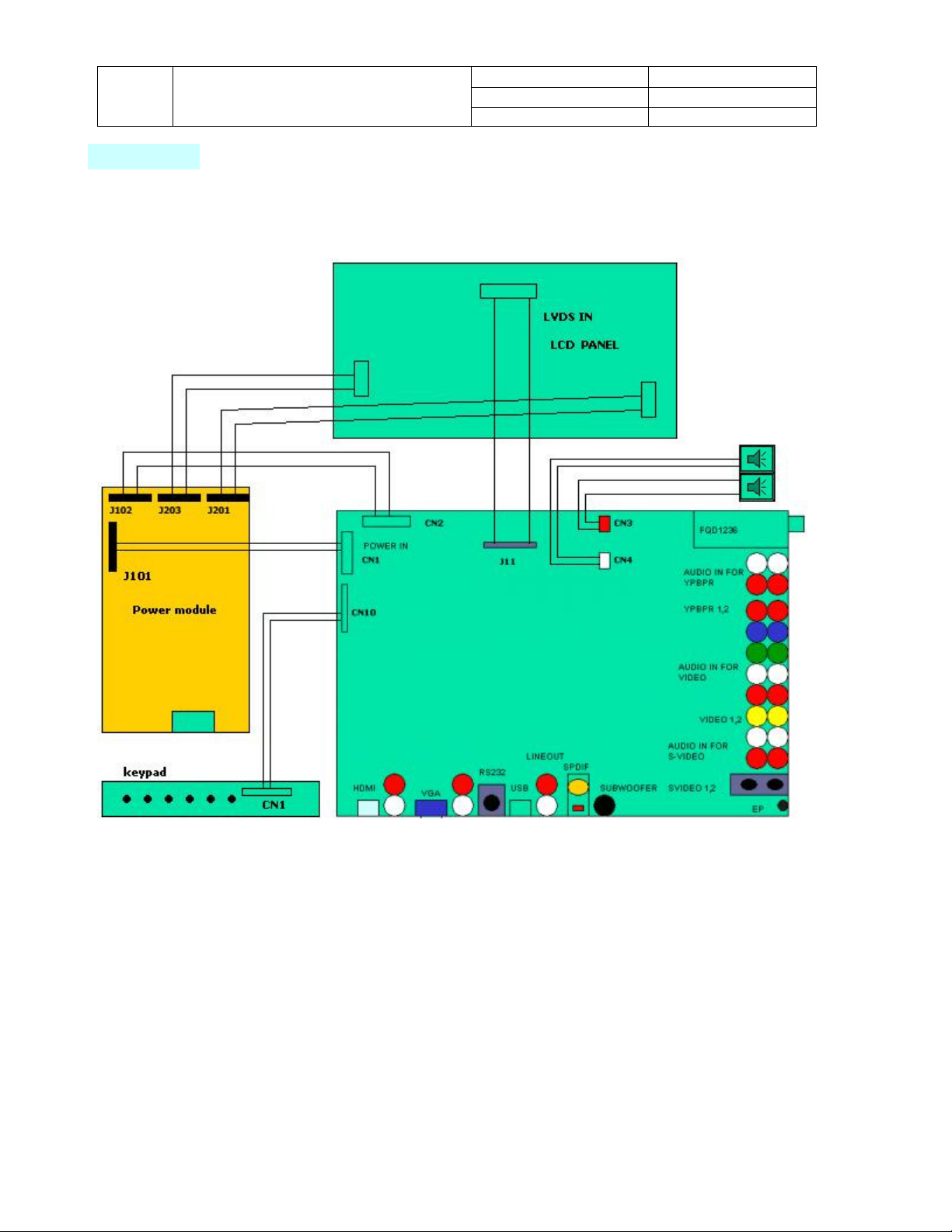
3-1 Wiring Diagram
Service Manual
LCD TV For 237-T11
Company Confidential-DRAFT
Doc No. SM_237-T11_19Nov07
Version 1.2
Page 9/72
Page 10
TITLE
Service Manual
LCD TV For 237-T11
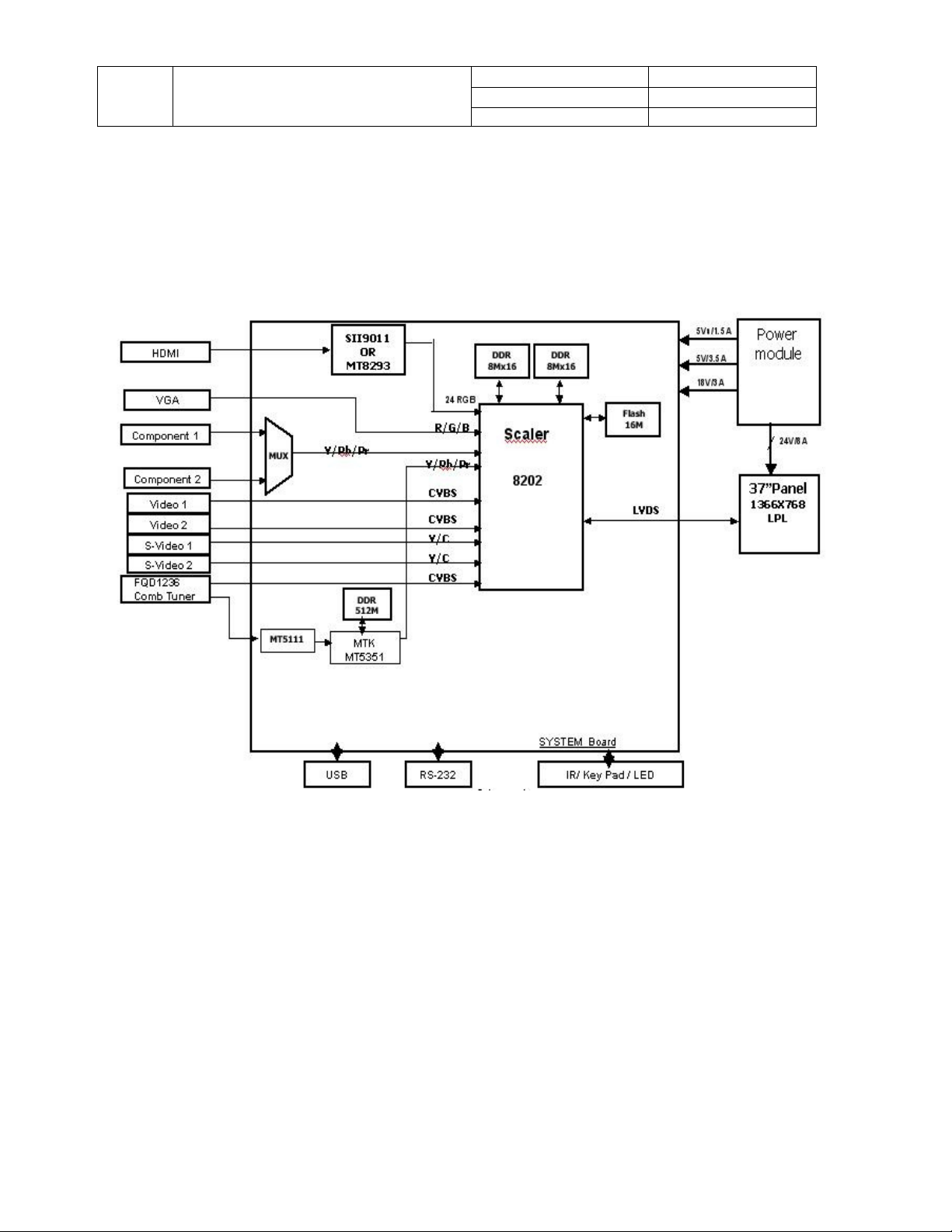
3-2 System Block Diagram (Video)
Doc No. SM_237-T11_19Nov07
Version 1.2
Page 10/72
Company Confidential-DRAFT
Page 11
TITLE
Service Manual
LCD TV For 237-T11
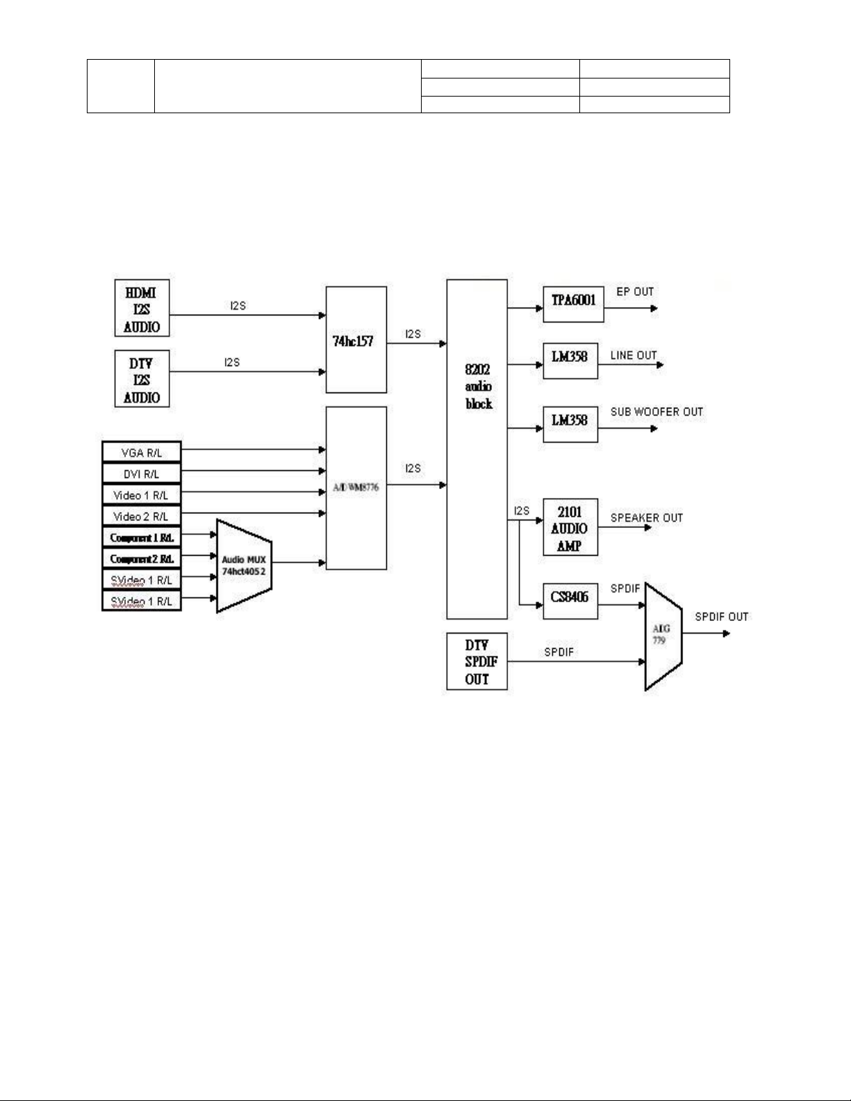
3-3 System Block Diagram (Audio)
Doc No. SM_237-T11_19Nov07
Version 1.2
Page 11/72
Company Confidential-DRAFT
Page 12
Doc No. SM_237-T11_19Nov07
Replace System
board if voltage
1. Check for a loose video
cable connection
3. Change source
Secure connection
Fai
l
Fai
l
Fai
l
Fai
l
Version 1.2
Page 12/72
TITLE
Service Manual
LCD TV For 237-T11
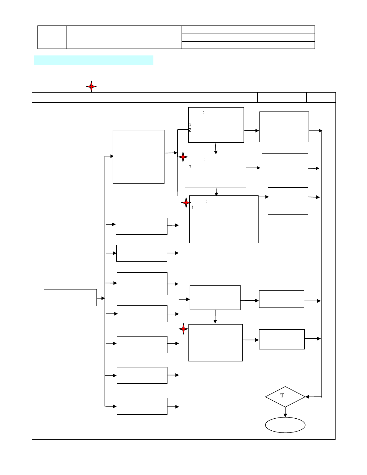
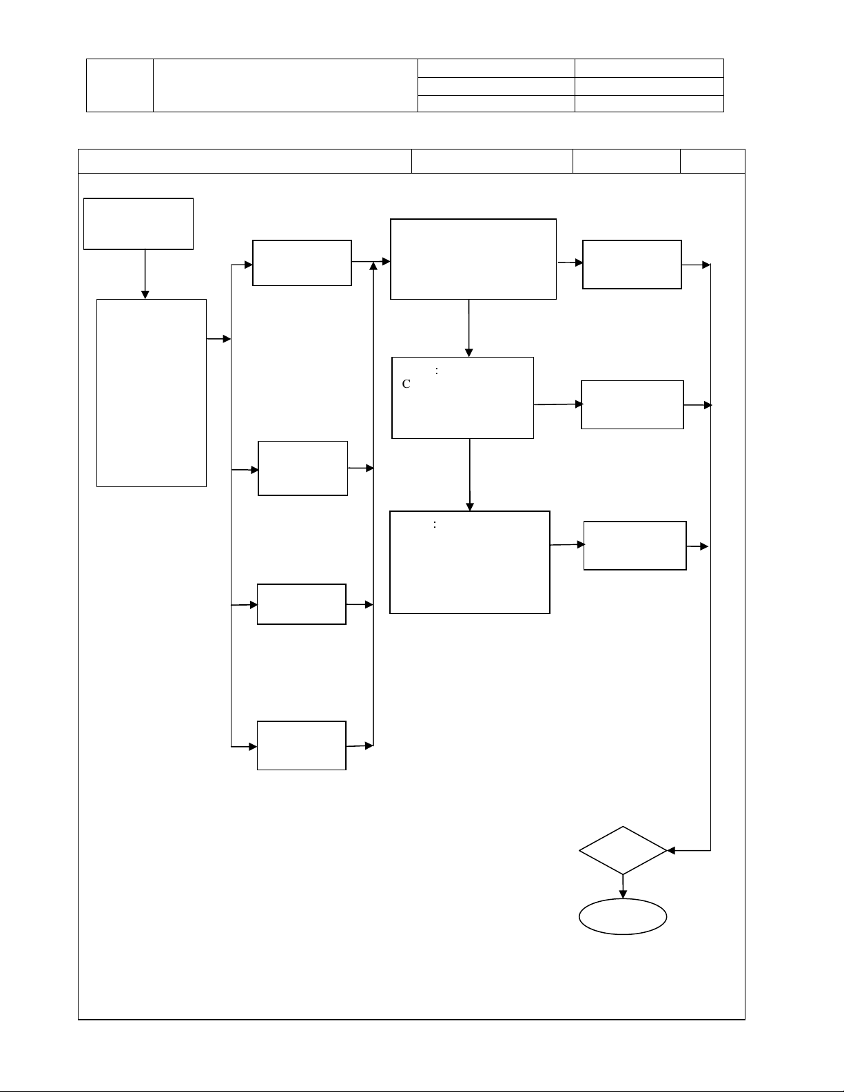
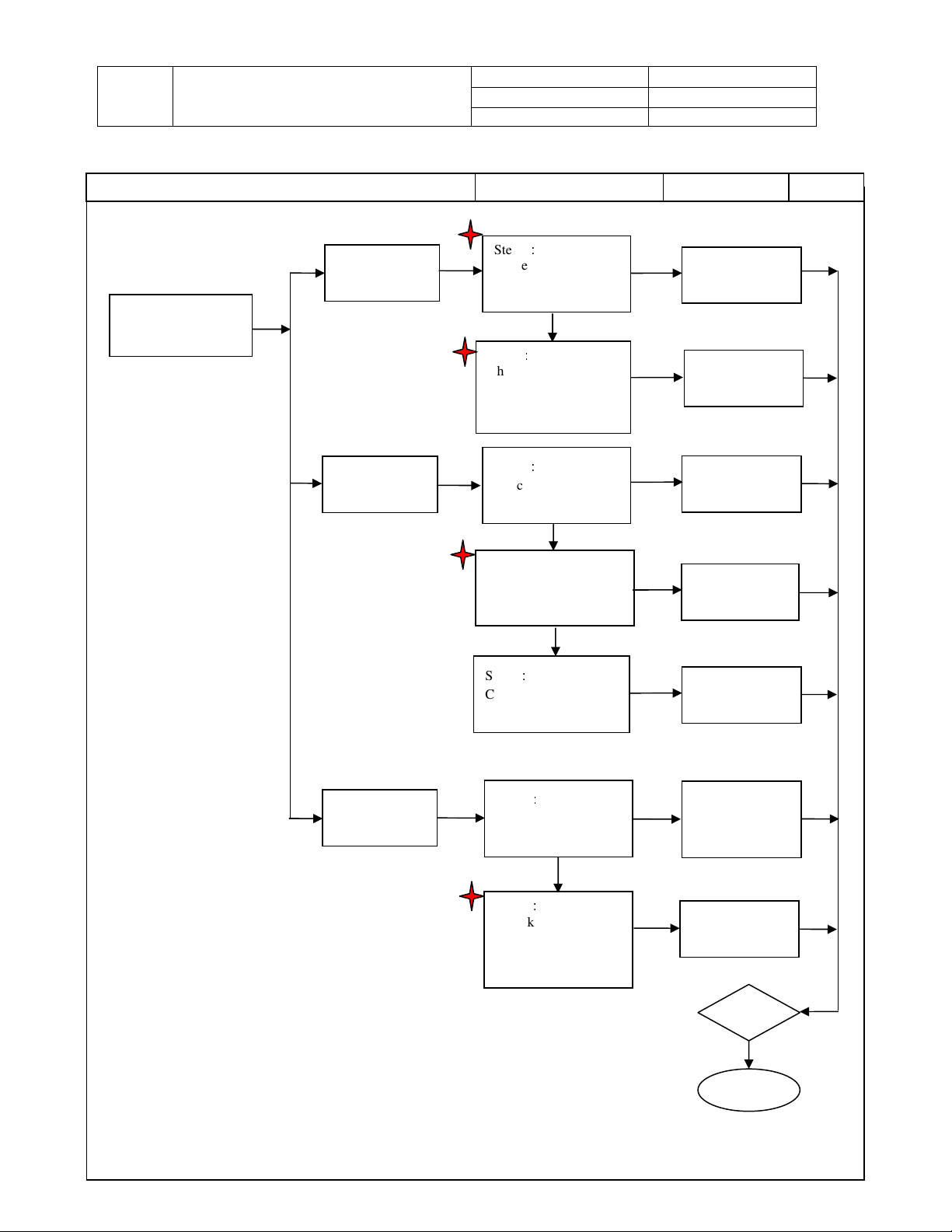
4. Trouble shooting flow chart
4-1 Display Problems
Note: Refer to the Wiring Diagram during troubleshooting for a visual of inter-connections when
indicated by this symbol.
Display Problems
Trouble Condition Check Item Replace Material Test
Abnormal display
1. No video Image
2. Video noise
3. Display flashes
4. Abnomal color
Bright spots
Dark spots
Backlight
uniformity
Light leakage
Spot & Simi
Ghosting
Dust & Scratch
Step1:
2. Check video cable
3. Check source settings
OK
Step2:
Check for a loose or broken
connection between
Con.J11from system board
to Panel LVDS connection.
OK
Step3:
1. Check System board
CN1-pin1 to ground = 5V,
pin3 to ground = 5V or
D4, D64 lighting
2. Check System Board
CN2-pin2 to ground = 12V
Step1:
Check damage to
panel
OK
Step2:
Check for a loose or
broken connection
between Con.J11from
system board to Panel
LVDS connection.
1. Reconnect cable
2. Replace cable
Fai
settings
4. Change TV input
or replace the
LVDS wire
Replace Panel
Replace LVDS
connect wire
is missing.
Test
Finish
Company Confidential-DRAFT
Page 13
TITLE
Abnormal Power
lighting?
Service Manual
LCD TV For 237-T11
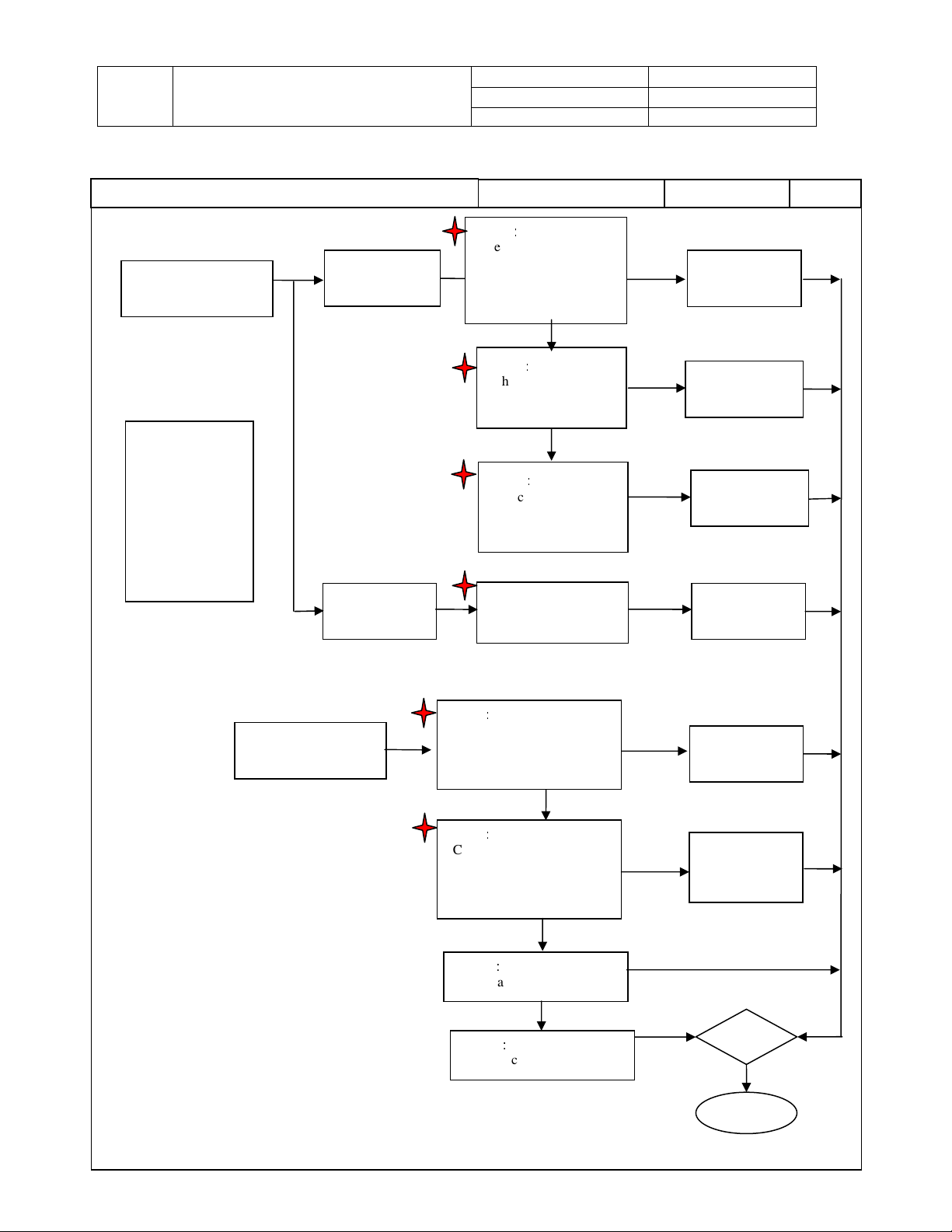
4-2 Abnormal Power On/Off
Trouble Condition Check Item
Abnormal Power
On/Off
No Power
Note: Before
proceeding
confirm that
Power cable is
connected and
that proper
voltage is being
fed to TV. (Check
power switch
located next to
power input and
confirm that it’s
ON.)
Shut down
Source can’t
Off
switch
Doc No. SM_237-T11_19Nov07
Version 1.2
Page 13/72
Step1:
Check Power Supply, Con.
J101–pin 1 to ground = 5V
Con CN1 pin 3 to ground =
5V
OK
Step2:
Check Keypad board
CN1-pin1 to ground =
5V or Check D1
OK
Step3:
Check System Board
CN1 pin1 to ground = 5Vs,
and pin3 to ground = 5V,
Check D4, D64 lighting?
Replace Material
Fail
Replace Power
Fail
Replace Keypad
Fail
Replace System
Test
supply
board
board
Test
Finish
Company Confidential-DRAFT
Page 14
TITLE
Con.
Secure connection
a loose connection
Service Manual
LCD TV For 237-T11
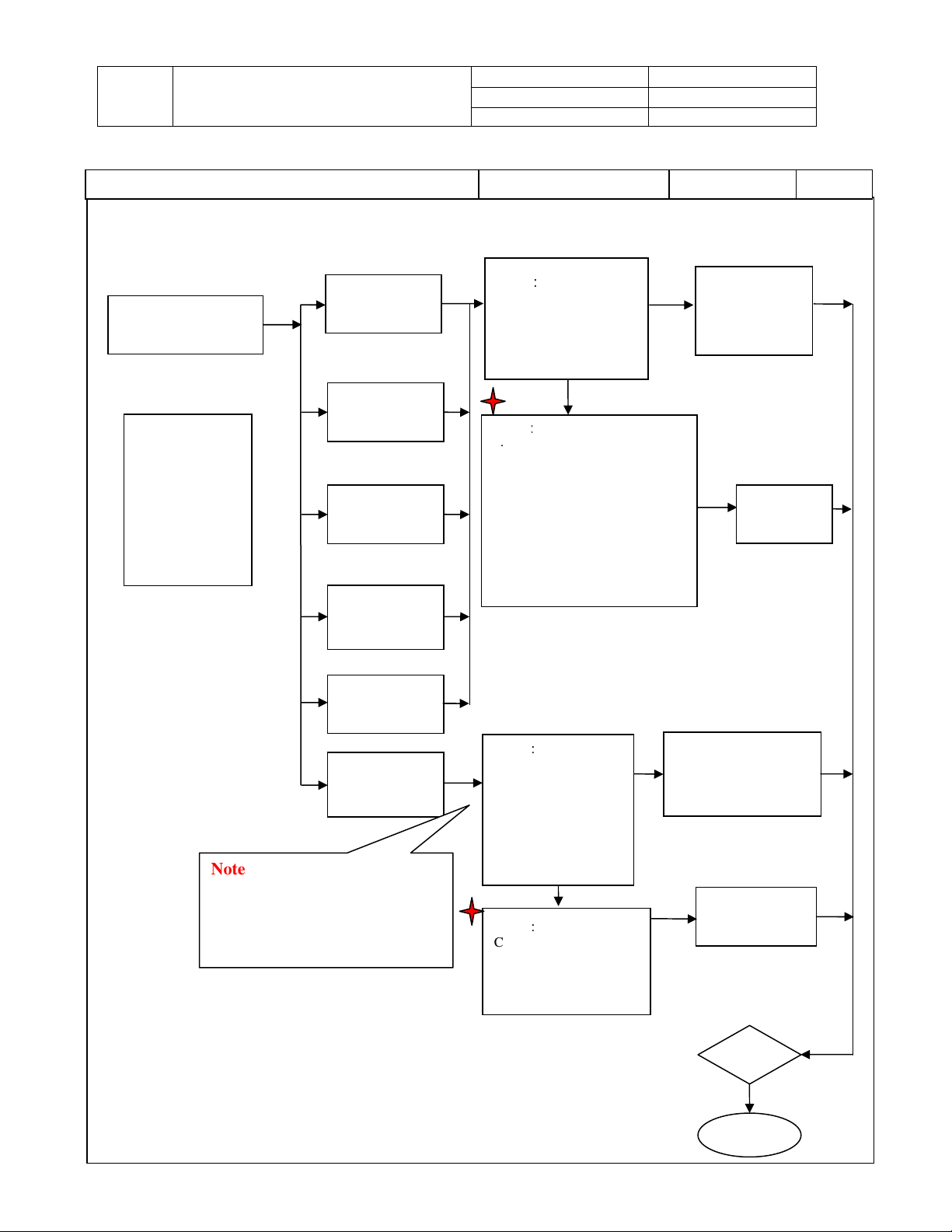
4-3 LED is Malfunctioning、、、、Keypad Problem
Trouble Condition
LED is Malfunctioning
LED is not working
Note: Before
proceeding
confirm that Power
cable is connected
and that proper
voltage is being
fed to TV. (Check
power switch
located next to
power input and
confirm that it’s
LED flashes
Keypad doesn’t work
Step1:
Check connector CN 10 on
System board to CN1
located on Keypad board for
Step2:
Check connector CN 10 on
System board to CN1
located on Keypad board for
Step 3:
Replace Keypad Board
Step 4:
Company Confidential-DRAFT
Doc No. SM_237-T11_19Nov07
Version 1.2
Page 14/72
Check Item
Step1:
Check CN 10 on system
board to CN 1 on
Keypad board for a
loose connection or bad
cable
OK
Step2:
Check Keypad board
D1 & CN1-pin 1 to
ground = 5V
OK
Step3:
Check System board
CN10-pin1 to ground
= 5V
Check Power supply
J101-pin1 to ground =5V
OK
a broken cable
OK
Fail
Replace System Board
Replace Material
Fail
Fail
Fail
Fail
Fail
Fail
Test
Secure connection
or replace cable
Replace board if
there is no voltage
Replace System
board if there is no
voltage
Replace Power
Supply if there is
no voltage
Replace Cable
Test
Finish
Page 15

TITLE
Service Manual
LCD TV For 237-T11
Doc No. SM_237-T11_19Nov07
Version 1.2
Page 15/72
Company Confidential-DRAFT
Page 16
TITLE
Replace System
resolution to
or loose pins.
Step2
:
4. Check TV input
Service Manual
LCD TV For 237-T11
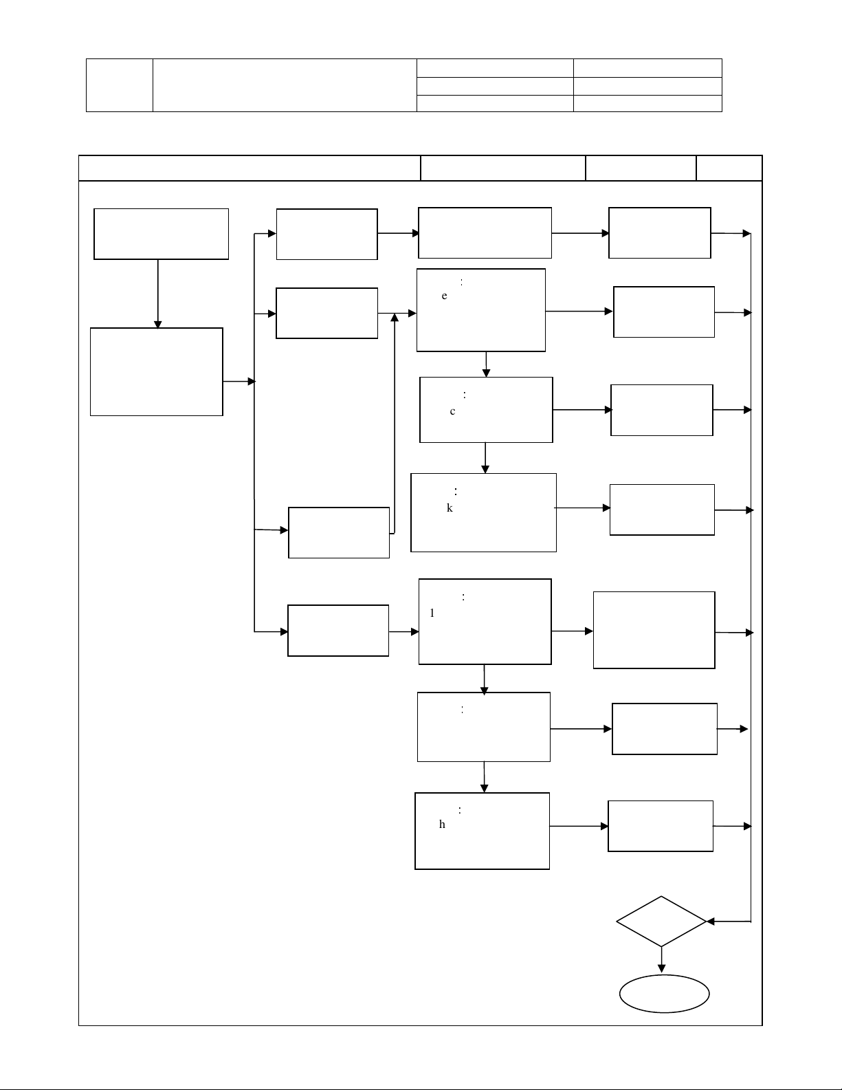
4-4 Image Abnormal Display
Trouble Condition Check Item
Image abnormal display
No picture through
Note: Before
proceeding
confirm that Power
cable is connected
and that proper
voltage is being
fed to TV. (Check
power switch
located next to
power input and
confirm that it’s
Note: Before proceeding make
sure the PC is not in standby or
hibernation mode. Make sure
the video card is secure and not
loose (AGP or PCI slot).
component
No picture through
composite
No picture through
S-Video
No Picture through
Tuner
No picture through
HDMI
No picture through
VGA
Doc No. SM_237-T11_19Nov07
Version 1.2
Page 16/72
Replace Material
Step1:
1. Check video cable
connection
2. Check video cable
3. Check source settings
OK
1. Check System Board
component L52, L49 L53, L50,
L54, L51 for a short.
2. Check System Board
component L65, L68 for a short
3. Check System Board
component L59, L61 L62, L60
for a short
4. Check System Board
component U103 for a short
5. Check CN9 broken? , D41
lighting? & U60 EDID OK?
Step1:
1. Check if VGA cable
is loose.
2. Make sure the PC is
set to a resolution the
TV supports
3. Check both ends of
VGA cable for broken
OK
Step2:
Check component J4 on
system board for a short
& component U26 that
stores EDID information
Fail
Fail
1. Reconnect cable
Fail
2. Replace cable
3. Change source
settings
4. Change TV input
Fail
1. Secure connection
2. Change PC
fit the timing table
3. Replace VGA cable
Replace System
Test
board
board
Test
Company Confidential-DRAFT
Finish
Page 17
TITLE
on
cable
re external audio
Service Manual
LCD TV For 237-T11
4-5 Audio Abnormal Output
Trouble Condition Check Item
Audio Problems
Can’t adjustment
Make su
connection is secure
before proceeding with
troubleshooting
Volume
No audio
Step3:
Check System board
No audio on one
side of speaker
No audio through
earphone
Company Confidential-DRAFT
CN2-pin1 to ground =
2V
Doc No. SM_237-T11_19Nov07
Version 1.2
Page 17/72
Check switches on the
keypad board
Step1:
Check for loose
connection between
CN3 and peaker and
CN4 and speaker
OK
Step2:
Check if the Speaker
module is broken
OK
Step1:
1. Check earphone
connection
2. Check earphone
OK
Step2:
Check OSD speaker
setting is off and not
OK
Step3:
Check System board
component J21 & Q12
for a short
Replace Material
Fail
Replace Keypad
Fail
Fail
Fail
Fail
Fail
Fail
Replace connect
Replace speaker
Replace System
1. Secure earphone
connection.
2. Replace Earphone
cable
Set the speaker
setting to off
Replace System
board
Test
board
wire
module
board
Test
Finish
Page 18
TITLE
Service Manual
LCD TV For 237-T11
4-6 The Other Abnormal Display
Trouble Condition Check Item
Sometimes picture
flashes
Other display problems
Remote control
Firmware update
fails
fails
Doc No. SM_237-T11_19Nov07
Version 1.2
Page 18/72
Step1:
Check Con. J11 to
panel LVDS
onnection
OK
Step2:
Check System board
component U7,
FB141, FB4 for a short
& Tp103 to Ground =
Step1:
Check Remote
control & Battery
Check connector CN
10 on System board to
CN1 located on
Keypad board for a
Step3:
Check for a broken
Keypad/IR board
Step1:
Check firmware
settings
Step2:
Check System board,
J1, P1 Connector or
U110, U5 switch IC
for a short
NO
OK
OK
OK
Replace Material
Fail
Fail
Fail
Fail
Fail
Fail
Fail
Replace Remote
control & Battery
Replace connect
Replace Keypad/IR
Update firmware
Replace System
Test
Replace LVDS
connect wire
Replace System
board
wire
board
setting process
board
Test
Finish
Company Confidential-DRAFT
Page 19

TITLE
LCD TV For 237-T11
5. Disassembly
5-1 Stand
5-2 Back Cover
Service Manual
Doc No. SM_237-T11_19Nov07
Version 1.2
Page 19/72
Screw T4*45-PH-Cross-Black
Screw T4*25-PH-Cross-Black
1. Loosen and remove 8 screws.
2. Safely remove the Stand.
SCREW T4 X 12
Screw MT4x8-PH-Cross-Black
1. Loosen and remove 17 screws.
2. Safely remove the Back Cover.
Company Confidential-DRAFT
Page 20
TITLE
Screw MT4x8
-PH-
Cross
-
Black
Screw
T3*
8
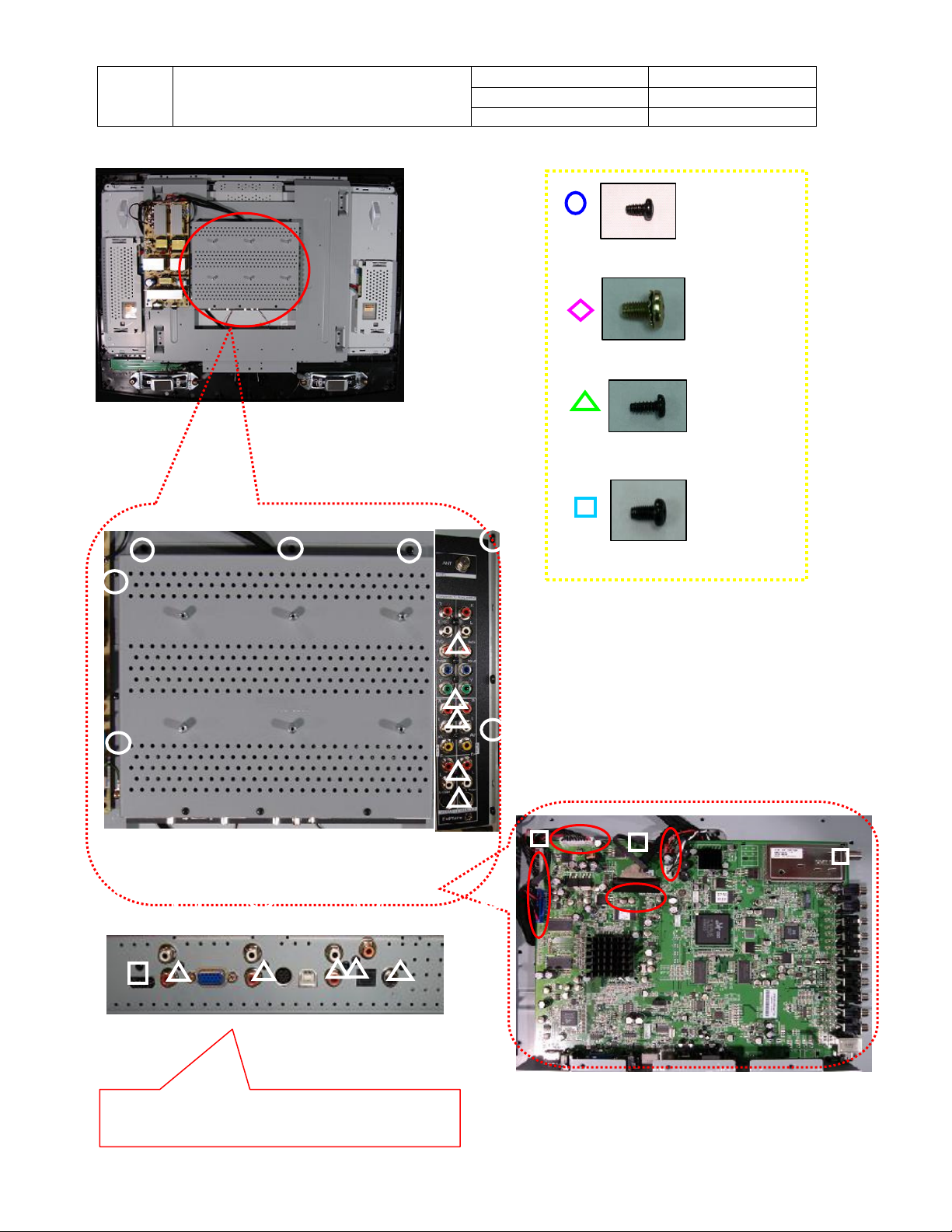
5-3 System Board
Service Manual
LCD TV For 237-T11
Doc No. SM_237-T11_19Nov07
Version 1.2
Page 20/72
MT3*6-PH-CROSS-Black
1. Loosen and remove 24 screws
2. Take off the WALLMOUNT Module
Company Confidential-DRAFT
Page 21

Doc No. SM_237-T11_19Nov07
Version 1.2
Page 21/72
TITLE
Service Manual
LCD TV For 237-T11
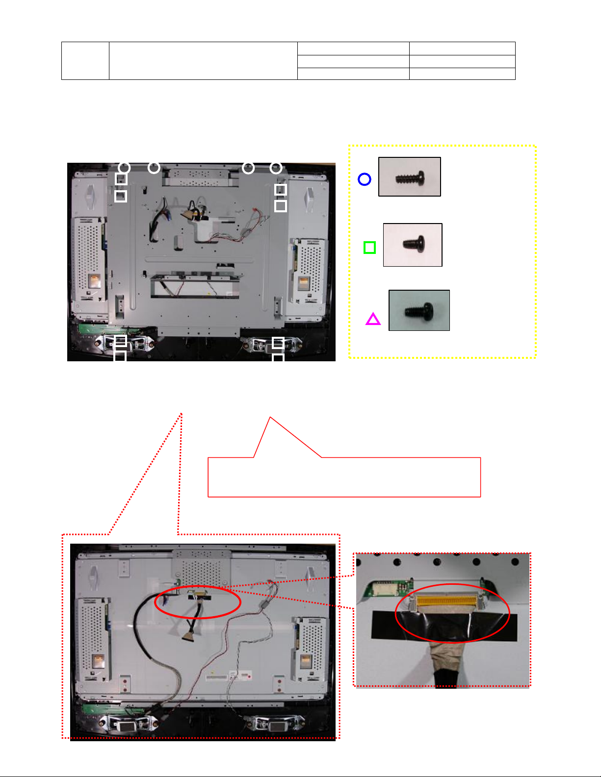
3. Loosen and remove 5 screws and safely remove connectors as indicated by red circles
4. Take off the System Board.
Company Confidential-DRAFT
Page 22
TITLE
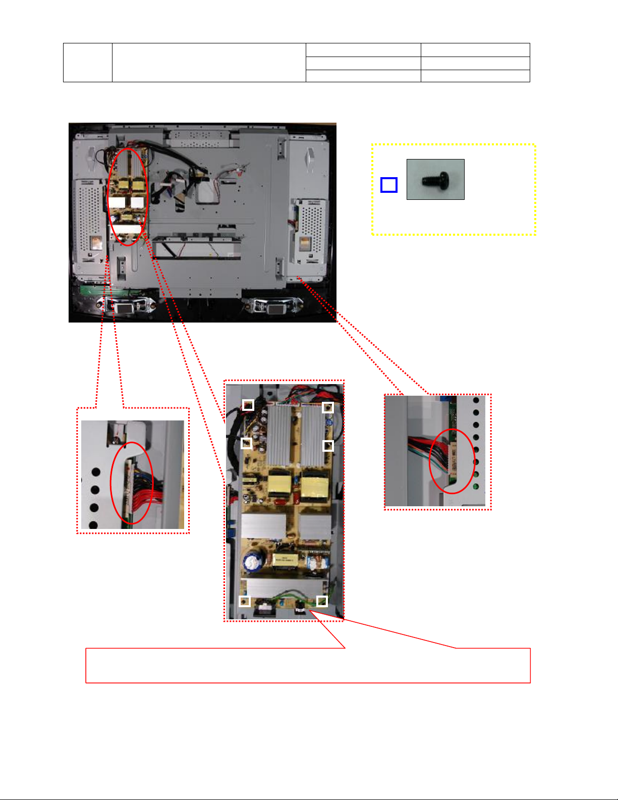
2. Safely remove
the
Power module
.
Service Manual
LCD TV For 237-T11
5-4 Power Module for LPL-WX1
Doc No. SM_237-T11_19Nov07
Version 1.2
Page 22/72
MT3*6-PH-CROSS-Black
1. Loosen and remove 6 screws and safely remove connectors indicated by red circles.
Company Confidential-DRAFT
Page 23

TITLE
Service Manual
LCD TV For 237-T11
Doc No. SM_237-T11_19Nov07
Version 1.2
Page 23/72
Company Confidential-DRAFT
Page 24
TITLE
Service Manual
LCD TV For 237-T11
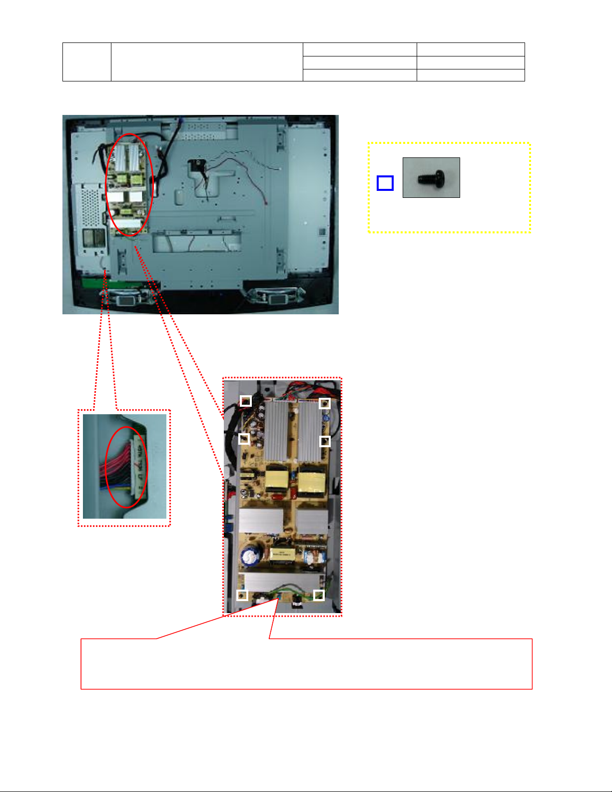
5-5 Power Module for LPL-WX4
Doc No. SM_237-T11_19Nov07
Version 1.2
Page 24/72
MT3*6-PH-CROSS-Black
1. Loosen and remove 6 screws and safely remove connectors indicated by red circles.
2. Safely remove the Power module.
Company Confidential-DRAFT
Page 25
TITLE
5-6 Panel Module
Service Manual
LCD TV For 237-T11
Doc No. SM_237-T11_19Nov07
Version 1.2
Page 25/72
Screw M4x12-Black
Screw MT4x8-PH-Cross-Black
MT3*6-PH-CROSS-Black
1. Loosen and remove 18 screws.
2. Take off the 37C_Support Metal Assy_MDA3
Company Confidential-DRAFT
Page 26

TITLE
LVDS wire
Service Manual
LCD TV For 237-T11
Doc No. SM_237-T11_19Nov07
Version 1.2
Page 26/72
3. Safely remove the
4. Remove the Panel Module
indicated by red circles.
Company Confidential-DRAFT
Page 27

TITLE
5-7 Speakers
Service Manual
LCD TV For 237-T11
Doc No. SM_237-T11_19Nov07
Version 1.2
Page 27/72
Screw MT4x10-W-H
1. Loosen and remove 4 screws.
2. Gently remove the speaker connectors that are indicated by a red circle.
3. Safely remove speakers.
Company Confidential-DRAFT
Page 28

TITLE
Service Manual
LCD TV For 237-T11
Doc No. SM_237-T11_19Nov07
Version 1.2
Page 28/72
Company Confidential-DRAFT
Page 29

TITLE
5-8 Keypad Board
Service Manual
LCD TV For 237-T11
Doc No. SM_237-T11_19Nov07
Version 1.2
Page 29/72
Screw T3*8 Black
MT3*6-PH-CROSS-Black
1. Loosen and remove 7 screws and safely
remvoe connector indicated by a red circle.
2. Safely remove the Keypad board.
6. Factory Menu
To show the Factory Menu with multiple pages.press these buttons at the same time:
Source,VOL↓, CHN↓.The FACTORY MENU appears on-screen.
Company Confidential-DRAFT
Page 30

TITLE
Service Manual
LCD TV For 237-T11
Doc No. SM_237-T11_19Nov07
Version 1.2
Page 30/72
Company Confidential-DRAFT
Page 31

Doc No. SM_237-T11_19Nov07
Version 1.2
Page 31/72
TITLE
Service Manual
LCD TV For 237-T11
7. Firmware upgrade
Olevia Firmware Updating Instructions
What does this do?
This process installs a new version of firmware that fixes or enhances your TV.
What products does this instruction apply to?
Model: Olevia 237, 437, 537 and 542
What do you need before installing?
1. A USB A to B cable.
2. A Computer with Microsoft® Windows® 2000 or Microsoft® Windows® XP
operating systems.
Important Notes:
1. Make sure that you are logged in to the computer as the Administrator or as a
user with installation rights.
2. Make sure that no other programs interfere with the installation, save your
work and close all other programs.
3. It is recommended to print the instructions to use as a reference before installing.
Loading Instructions:
1. Review the available downloads, the bugs fixed, and the new features added.
2. Create a directory to save the zip file and extract all files into the directory created.
3. Note: The following items are downloaded – make sure they are available under the same folder.
Company Confidential-DRAFT
Page 32

TITLE
Int
erface Tool to run.
Instructions
Service Manual
LCD TV For 237-T11
Firmware
Doc No. SM_237-T11_19Nov07
Version 1.2
Page 32/72
Necessary for
4. Connect USB cable from your computer to the TVs firmware upgrade port
located in the back of the unit.
Note: You are require to install the USB driver to assure proper communication
between the computer and television. This executable file is in the
“MTK8202 USB2UART drive” folder.
Firmware Download
Computer
USB Cable
USB Driver
Television
Interface Tool
PL-2303 Driver Installer.exe
Company Confidential-DRAFT
Page 33

Doc No. SM_237-T11_19Nov07
Version 1.2
Page 33/72
TITLE
Service Manual
LCD TV For 237-T11
5. Once you finish installing the USB driver, open the Interface Tool to begin downloading the
firmware.
6. Turn On the Television.
Mtk_DL_V1.4 A_20060601.exe
Company Confidential-DRAFT
Page 34

Doc No. SM_237-T11_19Nov07
Version 1.2
Page 34/72
TITLE
Service Manual
LCD TV For 237-T11
7. Press Step 1 to begin downloading the Firmware.
(Note: Will take roughly 15 seconds to begin loading firmware at which TV will turn off.)
8. When step 1 is complete, a message will prompt you to disconnect and connect the power cord.
(Press OK after you plug in the power cord.)
Company Confidential-DRAFT
Page 35

Doc No. SM_237-T11_19Nov07
Version 1.2
Page 35/72
TITLE
Service Manual
LCD TV For 237-T11
9. Connect Power Cable and continue to power on the television.
(Press the OK button after the television turns on.)
10. Press Step 2 to continue firmware loading.
(Note: Will take roughly 15 seconds to begin loading firmware.)
Company Confidential-DRAFT
Page 36

Doc No. SM_237-T11_19Nov07
Version 1.2
Page 36/72
TITLE
Service Manual
LCD TV For 237-T11
11. When step 2 is complete, a message will prompt you to disconnect and connect the power cord.
(Press OK after you plug in the power cord.)
12. Press the OK button and exit the Interface Tool. Disconnect the USB cable from your
TV/Computer.
Company Confidential-DRAFT
Page 37

Doc No. SM_237-T11_19Nov07
Version 1.2
Page 37/72
TITLE
Service Manual
LCD TV For 237-T11
13. Turn TV ON and check that firmware was successfully loaded.
(Press Menu to activate the On Screen Display – Scroll UP/DOWN to SET UP and press
Enter – Scroll UP/Down to Firmware Version and press Enter.)
Press Enter
Press Enter
Make sure the last 4
digits matches with the
firmware uploaded.
Company Confidential-DRAFT
Page 38

Doc No. SM_237-T11_19Nov07
MDA3
Version 1.2
Page 38/72
TITLE
Service Manual
LCD TV For 237-T11
8. EDID write in and ADC correction and Parameter Adjustment
8-1 EDID write in
8-1.1 EDID tools
1. PC(Notebook)
2. Software(EDID Write EEprom20060816.exe)and confirm Personal computer hard disk
8-1.2 EDID write in
Have 2 files (1. C:\EDID Editor(including Hex files) 2.C:\LCD TV\DATA(product and
record had No.)
Step 1
Step 2
Step 4
Step 3
Step 5
Step 6
Step 7
1. Open Labview EDID Writ Eeprom20060816 file, and confirm software Keep Running.(Refer
Step 1)
2. choice RS-232 (PC System)Port No.(Refer Step 2),choice burn in type (Refer Step 3)
3. press Set Model button(Refer Step 4), and key in 237-T11. and confirm Scalar solution (Refer
Step 5)
4. confirm EDID Jig PCBA (printer port and USB A-B Line connect to PC, HDMI line to TV first ,
MinDim RS-232 to TV)
5. and then press Button(Refer Step 6), then open a save file path in widow.
operate Barcode scanner scan S/N stick No.
6. First write HDMI EDID code , if finish OK you can find green light.(Refer Step 7)
7. And have a message that change EDID Jip PCBA VGA Cable to TV.(HDMI line must leave
PCBA Jig.) ,if write OK you can fine green light and show the message
Company Confidential-DRAFT
Page 39

TITLE
Photo 1
Photo 2
that change next set.
8-2 ADC correction and Parameter adjustment
Service Manual
LCD TV For 237-T11
Doc No. SM_237-T11_19Nov07
Version 1.2
ADC correction and Parameter adjustment tools:
1. PC(Notebook)
2. CHROMA 2325
3. MINOLTA CA-210
4. Software(Gamma Calculator6A_Jason.exe)
8-2.1 ADC correction
1. Click the icon on the desk "Gamma Calculator" (please see
Photo 1), and then Photo 2 would show up.
2. Click the icon "Gamma Calculator" of Photo 2, and then
Photo 3 would show up.
3. Connect "RS232" &"VGA" with TV.
4. click the "arrow mark" (which is circle by red) in Photo 3,
and then click the icon "ADC" also in Photo 3 blue circle.
5. The window will show up with the instruction about
component, and then connecting component instead of
VGA port.
6. The ADC process is completed once the window with the
message "OK" shows up.
Attention::::
1. Please make sure it's under "VGA Source" before
processing ADC.
2. Please pay attention to different solution for
ATI/MTK8202/PW106 as Photo 3 green circle.
3. Please make sure the set-up for RS232 is correct.
Company Confidential-DRAFT
Page 39/72
Page 40

TITLE
Service Manual
LCD TV For 237-T11
Doc No. SM_237-T11_19Nov07
Version 1.2
Page 40/72
Company Confidential-DRAFT
Page 41

TITLE
Photo 4
Photo 5
Photo 6
Photo 7
Photo 8
Photo 9
8-2.2 Parameter adjustment
Service Manual
LCD TV For 237-T11
1. Click the icon on the desk "Gamma Calculator" (please
see Photo 1), and then Photo 2 would show up.
2. Click the icon "Gamma Calculator" of Photo 2, and
then Photo 3 would show up.
3. Please follow (as Photo 4 blue circle) to choose the
solution & panel mode.
4. Connect the" RS232, USB, VGA changeful wire, and
audio wire" with TV. And then connect the other side
of VGA changeful wire with the pattern generator, and
set up the TV source under "VGA". And please locate
the "CA-210" on center of TV screen.
5. Click "BL" button, and the window with "Gamma
adjustment" message would show up. Please click
"OK" for next step. (as Photo 4 red circle)
6. Adjust the GAMMA (R;G;B) and then click the button
"Enter" after GAMMA adjustment is
completed.(Please follow Photo 5, 6)
7. Please check the result.
Attention::::
Check pattern points for adjustment
(CHROMA PROGRAM::::71 1360_FT_VGA )::::
1. Check if the frame is damaged and if the size is
smaller than normal, or if those points in the 5
squares correspond well. (Photo 7)
2. Each gray bar should be identified with only pure
color.(Photo 8)
3. 256 Gray. L->R--->check if there is sync
(influenced by high frequency). (Photo 9)
Doc No. SM_237-T11_19Nov07
Version 1.2
Page 41/72
Company Confidential-DRAFT
Page 42

TITLE
LCD TV For 237-T11
9.Exploded view
Service Manual
Doc No. SM_237-T11_19Nov07
Version 1.2
Page 42/72
Company Confidential-DRAFT
Page 43

Doc No. SM_237-T11_19Nov07
Version 1.2
Page 43/72
TITLE
Service Manual
LCD TV For 237-T11
10. Parts List and Photo
10-1 PARTS LIST For LPL WX1-SL01 (See 10.2 Parts Photo)
237-T11 For WX1-SL01 Parts List-SL01(FM1-037000EGS25)
Item
1 537 MDA3 power module
2 LG 37" LCD panel (w/AI)
3 P0519 MDA3 System PCBA
4 MDA3 Keypad PCBA
5 37C_B_FRONT _MODULE_L9524_TCV
6 37C_B_Back Cover MODULE_TCV
7 Flat Cable Clip_FAA51-PG
8 32_37C_KEYPAD_BUTTON
9 Graphic Label for MDA3
10 37C_Support Metal Assy_MDA3
11 37C WALLMOUNT Module
12 MTK 32" LPL LVDS wire
13 SCREW T4 X 12
14 SCREW /NI/MT4*8
15 SCREW MT4*8-PH-CROSS-BLACK
16 SCREW T3*8 Black
17 SCREW MT3*6-PH-CROSS-Black
18 SCREW /T4*10/Ni
19 TV barcode label
20 S/N lebel 15*44mm
21 RIBBON
22 Heatproof tape
23 237T Marketing Label_GP
24 537_542 tech label-Dolby
25 MD1 40" keypad wire+Magnet buckle
26 37C_Speaker_Module_R+ Magnet buckle
27 37C_Speaker_Module_Left+ Magnet buckle
28 Power on Label-2
29 37" Panel Protection Film
30 Screw T4*45-PH-Cross-Black
31 Screw T4*25-PH-Cross-Black
32 37C_STAND_COVER_2nd
33 32 FOOT PAD
34 Condnctive shielding tapeVGA Port
35 Condnctive shielding tape
36 Condnctive shielding tape
37 Condnctive shielding tape
38 Magnet buckle-B15-UH-13x23x7
39 337 claspless cushion bottom
Parts Name Parts NO.
EEC-PWAEP01G000
ELP-37WX1SLG000
SC0-P519201GMI4
SC0-P517701GMI0
SX0-0000324G000
SX0-0000320G000
EEC-FCFAA51G000
MP0-0000497G000
ML0-0000263G000
SX0-0000273G000
SX0-0000274G000
ECB-5LC0118G000
MS0-WA34012G000
MS0-FA14008G000
MS0-WA34008G000
MS0-WA33008G000
MS0-A133006G000
MS0-WA14010G000
ML0-0000016G000
ML0-0000015G000
MX0-0000000G000
MP2-0000175G000
ML0-1000155G000
ML0-0000314G002
SX0-0000446G000
SX0-0000441G000
SX0-0000442G000
ML0-0000438G000
MP0-0000730G000
MS0-1A34045G000
MS0-BA34025G000
MP0-0000535G001
MM0-0000034G000
EEC-EM13234G000
EEC-EM30202G000
EEC-EML10W2G000
EEC-EM22033G000
EEC-PLB15UHG000
MP2-1000043G000
Company Confidential-DRAFT
Page 44

TITLE
40 37C_CUSHING-TOP
37C EPE Bag MP2-0000162G000
41
42 TEAM LIFT Label
43 Drawing paper 1080x910
44 37C3_B_PROTECTION PAPER
45 RFID tag for Target models
46 BARCODE W90mm*60mm
47 Barcode ribbon transfer paper
48 237-T11 Carton w /weee logo
49 AC Power Cord
50 LT23HVT remote control
51 Olevia_HookUp_8_(En/Fr)
52 Battery
53 Ziploc bags#10(W/O LOGO)
54 CD-En-Fr_ATi_MTK_2 Series_T-2
55 QSG-En-Fr_MTK_237_Target-1
56 OSD Tree Guide
57 TFHD Series Warranty Card
58 Power on Guide-1
Service Manual
LCD TV For 237-T11
Doc No. SM_237-T11_19Nov07
Version 1.2
Page 44/72
MP2-1000031G000
ML0-0000393G000
MX0-0000079G000
MX0-0000100G000
ML0-0000455G000
ML0-0000195G000
ML0-0000017G000
MX0-3000326G000
ECB-0318AW8G000
EEC-RC0CG37G000
MK0-UM00124G000
EEC-BAGP24GG000
MX0-0000025G000
MD0-CD00073G000
MK0-QS00097G000
MK0-QS00092G000
MK0-WC00048G000
MK0-QS00102G000
Company Confidential-DRAFT
Page 45

Doc No. SM_237-T11_19Nov07
Version 1.2
Page 45/72
TITLE
Service Manual
LCD TV For 237-T11
10-2 PARTS PHOTO For LPL WX1-SL01 (See 10.1 Parts list )
Item NO:1
Parts name:537 MDA3 power module
Parts NO. :EEC-PWAEP01G000
Item NO:2
Parts name:LG 37" LCD panel (w/AI)
Parts NO. :ELP-37WX1SLG000
Item NO:3
Parts name:P0519 MDA3 System PCBA
Parts NO. :SC0-P519201GMI4
Item NO:4
Parts name:MDA3 Keypad PCBA
Parts NO. :SC0-P517701GMI0
Item NO:5
Parts name:
37C_B_FRONT _MODULE_L9524_TCV
Parts NO. :SX0-0000324G000
Item NO:6
Parts name:
37C_B_Back Cover MODULE_TCV
Parts NO. :SX0-0000320G000
Company Confidential-DRAFT
Page 46

TITLE
Service Manual
LCD TV For 237-T11
Item NO:7
Parts name:Flat Cable Clip_FAA51-PG
Parts NO :EEC-FCFAA51G000
Item NO:9
Parts name:Graphic Label for MDA3
Parts NO. :ML0-0000263G000
Item NO:11
Parts name:37C WALLMOUNT Module
Parts NO. :SX0-0000274G000
Doc No. SM_237-T11_19Nov07
Version 1.2
Page 46/72
Item NO:8
Parts name:32_37C_KEYPAD_BUTTON
Parts NO. :MP0-0000497G000
Item NO:10
Parts name:37C_Support Metal Assy_MDA3
Parts NO. :SX0-0000273G000
Item NO:12
Parts name:MTK 32" LPL LVDS wire
Parts NO. :ECB-5LC0118G000
Company Confidential-DRAFT
Page 47

TITLE
Service Manual
LCD TV For 237-T11
Item NO:13
Parts name:SCREW T4 X 12
Parts NO. :MS0-WA34012G000
Item NO:15
Parts name:
SCREW MT4*8-PH-CROSS-BLACK
Parts NO. :MS0-WA34008G000
Item NO:17
Parts name:
SCREW MT3*6-PH-CROSS-Black
Parts NO. :MS0-A133006G000
Doc No. SM_237-T11_19Nov07
Version 1.2
Page 47/72
Item NO:14
Parts name:SCREW /NI/MT4*8
Parts NO. :MS0-FA14008G000
Item NO:16
Parts name:SCREW T3*8 Black
Parts NO. :MS0-WA33008G000
Item NO:18
Parts name:SCREW /T4*10/Ni
Parts NO. :MS0-WA14010G000
Company Confidential-DRAFT
Page 48

TITLE
Service Manual
LCD TV For 237-T11
Item NO:19
Parts name:TV barcode label
Parts NO. :ML0-0000016G000
Item NO:21
Parts name:RIBBON
Parts NO. :MX0-0000000G000
Item NO:23
Parts name:237T Marketing Label_GP
Parts NO. :ML0-1000155G000
Doc No. SM_237-T11_19Nov07
Version 1.2
Page 48/72
Item NO:20
Parts name:S/N lebel 15*44mm
Parts NO :ML0-0000015G000
Item NO:22
Parts name:Heatproof tape
Parts NO. :MP2-0000175G000
Item NO:24
Parts name:537_542 tech label-Dolby
Parts NO. :ML0-0000314G002
Company Confidential-DRAFT
Page 49

TITLE
Service Manual
LCD TV For 237-T11
Item NO:25
Parts name:
MD1 40" keypad wire+Magnet buckle
Parts NO. :SX0-0000446G000
Item NO:27
Parts name:
37C_Speaker_Module_Left+ Magnet buckle
Parts NO. :SX0-0000442G000
Item NO:29
Doc No. SM_237-T11_19Nov07
Version 1.2
Page 49/72
Item NO:26
Parts name:
37C_Speaker_Module_R+ Magnet buckle
Parts NO. :SX0-0000441G000
Item NO:28
Parts name:Power on Label-2
Parts NO. :ML0-0000438G000
Item NO:30
:
Parts name:37" Panel Protection Film
Parts NO. :MP0-0000730G000
Parts name:Screw T4*45-PH-Cross-Black
Parts NO. :MS0-1A34045G000
Company Confidential-DRAFT
Page 50

TITLE
Service Manual
LCD TV For 237-T11
Item NO:31
Parts name:Screw T4*25-PH-Cross-Black
Parts NO. :MS0-BA34025G000
Item NO:33
Parts name:32 FOOT PAD
Parts NO. :MM0-0000034G000
Item NO:35
Parts name:Condnctive shielding foam
Parts NO. :EEC-EM30202G000
Doc No. SM_237-T11_19Nov07
Version 1.2
Page 50/72
Item NO:32
Parts name:37C_STAND_COVER_2nd
Parts NO. :MP0-0000535G001
Item NO:34
Parts name:
Condnctive shielding foam VGA foam
Parts NO. :EEC-EM13234G000
Item NO:36
Parts name:Condnctive shielding foam
Parts NO. :EEC-EML10W2G000
Company Confidential-DRAFT
Page 51

TITLE
Service Manual
LCD TV For 237-T11
Item NO:37
Parts name:Condnctive shielding foam
Parts NO. :EEC-EM22033G000
Item NO:39
Parts name:337 claspless cushion bottom
Parts NO. :MP2-1000043G000
Item NO:41
Parts name:37C EPE Bag
Parts NO. :MP2-0000162G000
Doc No. SM_237-T11_19Nov07
Version 1.2
Page 51/72
Item NO:38
Parts name:Magnet buckle-B15-UH-13x23x7
Parts NO. :EEC-PLB15UHG000
Item NO:40
Parts name:37C_CUSHING-TOP
Parts NO. :MP2-1000031G000
Item NO:42
Parts name:TEAM LIFT Label
Parts NO. :ML0-0000393G000
Company Confidential-DRAFT
Page 52

TITLE
Service Manual
LCD TV For 237-T11
Item NO:43
Parts name:Drawing paper 1080x910
Parts NO. :MX0-0000079G000
Item NO:45
Parts name:RFID tag for Target models
Parts NO. :ML0-0000455G000
Item NO:47
Parts name:Barcode ribbon transfer paper
Parts NO. :ML0-0000017G000
Doc No. SM_237-T11_19Nov07
Version 1.2
Page 52/72
Item NO:44
Parts name:37C3_B_PROTECTION PAPER
Parts NO. :MX0-0000100G000
Item NO:46
Parts name:BARCODE W90mm*60mm
Parts NO. :ML0-0000195G000
Item NO:48
Parts name:237-T11 Carton w /weee logo
Parts NO. :MX0-3000326G000
Company Confidential-DRAFT
Page 53

TITLE
Service Manual
LCD TV For 237-T11
Item NO:49
Parts name:AC Power Cord
Parts NO. :ECB-0318AW8G000
Item NO:51
Parts name:Olevia_HookUp_8_(En/Fr)
Parts NO. :MK0-UM00124G000
Item NO:53
Parts name:Ziploc bags#10(W/O LOGO)
Parts NO. :MX0-0000025G000
Doc No. SM_237-T11_19Nov07
Version 1.2
Page 53/72
Item NO:50
Parts name:LT23HVT remote control
Parts NO. :EEC-RC0CG37G000
Item NO:52
Parts name:Battery
Parts NO. :EEC-BAGP24GG000
Item NO:54
Parts name:
CD-En-Fr_ATi_MTK_2 Series_T-2
Parts NO. :MD0-CD00073G000
Company Confidential-DRAFT
Page 54

TITLE
Service Manual
LCD TV For 237-T11
Item NO:55
Parts name:QSG-En-Fr_MTK_237_Target-1
Parts NO. :MK0-QS00097G000
Item NO:57
Parts name:TFHD Series Warranty Card
Parts NO. :MK0-WC00048G000
Doc No. SM_237-T11_19Nov07
Version 1.2
Page 54/72
Item NO:56
Parts name:OSD Tree Guide
Parts NO. :MK0-QS00092G000
Item NO:58
Parts name:Power on Guide-1
Parts NO. :MK0-QS00102G000
Company Confidential-DRAFT
Page 55

Doc No. SM_237-T11_19Nov07
Version 1.2
Page 55/72
TITLE
Service Manual
LCD TV For 237-T11
10-3 PARTS LIST For LPL WX1-SLA1 (See 10.4 Parts Photo)
237-T11 For LPL WX1-SLA1 Parts List-SL01(FM1-037000EGS36)
Item
1 271W power module
2 LPL 37" WXGA LC370WX1-SLA1
3 P0519 MDA3 System PCBA
4 MDA3 Keypad PCBA
5 37C_B_FRONT _MODULE_L9524_TCV
6 37C_B_Back Cover MODULE_TCV
7 Flat Cable Clip_FAA51-PG
8 32_37C_KEYPAD_BUTTON
9 Graphic Label for MDA3
10 37C_Support Metal Assy_MDA3
11 37C WALLMOUNT Module
12 MTK 32" LPL LVDS wire
13 SCREW T4 X 12
14 SCREW/NI/MT4*8
15 SCREW MT4*8-PH-CROSS-BLACK
16 SCREW T3*8 Black
17 SCREW MT3*6-PH-CROSS-Black
18 SCREW/T4*10/Ni
19 TV barcode label
20 S/N label 15*44mm
21 RIBBON
22 Heatproof tape
23 237T Marketing Label_GP
24 537_542 tech label-Dolby
25 MD1 40" keypad wire+Magnet buckle
26 37C_Speaker_Module_R+ Magnet buckle
27 37C_Speaker_Module_Left+ Magnet buckle
28 Power on Label-2
29 37" Panel Protection Film
30 Screw T4*45-PH-Cross-Black
31 Screw T4*25-PH-Cross-Black
32 37C_STAND_COVER_2nd
33 32 FOOT PAD
34 Condnctive shielding foam VGA Port
35 Condnctive shielding foam
36 Condnctive shielding foam
37 Condnctive shielding foam
38 Magnet buckle B15-UH-13x23x7
39 337 claspless cushion bottom
Parts Name Parts NO.
EEC-PWLC370G000
ELP-371SLA1G000
SC0-P519201GMI4
SC0-P517701GMI0
SX0-0000324G000
SX0-0000320G000
EEC-FCFAA51G000
MP0-0000497G000
ML0-0000263G000
SX0-0000273G000
SX0-0000274G000
ECB-5LC0118G000
MS0-WA34012G000
MS0-FA14008G000
MS0-WA34008G000
MS0-WA33008G000
MS0-A133006G000
MS0-WA14010G000
ML0-0000016G000
ML0-0000015G000
MX0-0000000G000
MP2-0000175G000
ML0-1000155G000
ML0-0000314G002
SX0-0000446G000
SX0-0000441G000
SX0-0000442G000
ML0-0000438G000
MP0-0000730G000
MS0-1A34045G000
MS0-BA34025G000
MP0-0000535G001
MM0-0000034G000
EEC-EM13234G000
EEC-EM30202G000
EEC-EML10W2G000
EEC-EM22033G000
EEC-PLB15UHG000
MP2-1000043G000
Company Confidential-DRAFT
Page 56

TITLE
40 37C_CUSHING-TOP
37C EPE Bag
41
42 TEAM LIFT Label
43 Drawing paper 1080x910
44 37C3_B_PROTECTION PAPER
45 RFID tag for Target models
46 BARCODE W90mm*60mm
47 Barcode ribbon transfer paper
48 237-T11 Carton w /weee logo
49 AC Power Cord
50 LT23HVT remote control
51 Olevia_HookUp_8_(En/Fr)
52 Battery
53 Ziploc bags #10(W/O LOGO)
54 CD-En-Fr_ATi_MTK_2 Series_T-2
55 QSG-En-Fr_MTK_237_Target-1
56 OSD Tree Guide
57 TFHD Series Warranty Card
58 Power on Guide-1
Service Manual
LCD TV For 237-T11
Doc No. SM_237-T11_19Nov07
Version 1.2
Page 56/72
MP2-1000031G000
MP2-0000162G000
ML0-0000393G000
MX0-0000079G000
MX0-0000100G000
ML0-0000455G000
ML0-0000195G000
ML0-0000017G000
MX0-3000326G000
ECB-0318AW8G000
EEC-RC0CG37G000
MK0-UM00124G000
EEC-BAGP24GG000
MX0-0000025G000
MD0-CD00073G000
MK0-QS00097G000
MK0-QS00092G000
MK0-WC00048G000
MK0-QS00102G000
Company Confidential-DRAFT
Page 57

Doc No. SM_237-T11_19Nov07
Version 1.2
Page 57/72
TITLE
Service Manual
LCD TV For 237-T11
10-4 PARTS PHOTO For LPL WX1-SLA1 (See 10.3 Parts list )
Item NO:1
Parts name:271W power module
Parts NO. :EEC-PWLC370G000
Item NO:2
Parts name:
LPL 37" WXGA LC370WX1-SLA1
Parts NO. :ELP-371SLA1G000
Item NO:3
Parts name:P0519 MDA3 System PCBA
Parts NO. :SC0-P519201GMI4
Item NO:4
Parts name:MDA3 Keypad PCBA
Parts NO. :SC0-P517701GMI0
Item NO:5
Parts name:
37C_B_FRONT _MODULE_L9524_TCV
Parts NO. :SX0-0000324G000
Item NO:6
Parts name:
37C_B_Back Cover MODULE_TCV
Parts NO. :SX0-0000320G000
Company Confidential-DRAFT
Page 58

TITLE
Service Manual
LCD TV For 237-T11
Item NO:7
Parts name:Flat Cable Clip_FAA51-PG
Parts NO :EEC-FCFAA51G000
Item NO:9
Parts name:Graphic Label for MDA3
Parts NO. :ML0-0000263G000
Item NO:11
Parts name:37C WALLMOUNT Module
Parts NO. :SX0-0000274G000
Doc No. SM_237-T11_19Nov07
Version 1.2
Page 58/72
Item NO:8
Parts name:32_37C_KEYPAD_BUTTON
Parts NO. :MP0-0000497G000
Item NO:10
Parts name:37C_Support Metal Assy_MDA3
Parts NO. :SX0-0000273G000
Item NO:12
Parts name:MTK 32" LPL LVDS wire
Parts NO. :ECB-5LC0118G000
Company Confidential-DRAFT
Page 59

TITLE
Service Manual
LCD TV For 237-T11
Item NO:13
Parts name:SCREW T4 X 12
Parts NO. :MS0-WA34012G000
Item NO:15
Parts name:
SCREW MT4*8-PH-CROSS-BLACK
Parts NO. :MS0-WA34008G000
Item NO:17
Parts name:
SCREW MT3*6-PH-CROSS-Black
Parts NO. :MS0-A133006G000
Doc No. SM_237-T11_19Nov07
Version 1.2
Page 59/72
Item NO:14
Parts name:SCREW /NI/MT4*8
Parts NO. :MS0-FA14008G000
Item NO:16
Parts name:SCREW T3*8 Black
Parts NO. :MS0-WA33008G000
Item NO:18
Parts name:SCREW /T4*10/Ni
Parts NO. :MS0-WA14010G000
Company Confidential-DRAFT
Page 60

TITLE
Service Manual
LCD TV For 237-T11
Item NO:19
Parts name:TV barcode label
Parts NO. :ML0-0000016G000
Item NO:21
Parts name:RIBBON
Parts NO. :MX0-0000000G000
Item NO:23
Parts name:237T Marketing Label_GP
Parts NO. :ML0-1000155G000
Doc No. SM_237-T11_19Nov07
Version 1.2
Page 60/72
Item NO:20
Parts name:S/N lebel 15*44mm
Parts NO :ML0-0000015G000
Item NO:22
Parts name:Heatproof tape
Parts NO. :MP2-0000175G000
Item NO:24
Parts name:537_542 tech label-Dolby
Parts NO. :ML0-0000314G002
Company Confidential-DRAFT
Page 61

TITLE
Service Manual
LCD TV For 237-T11
Item NO:25
Parts name:
MD1 40" keypad wire+Magnet buckle
Parts NO. :SX0-0000446G000
Item NO:27
Parts name:
37C_Speaker_Module_Left+ Magnet buckle
Parts NO. :SX0-0000442G000
Item NO:29
Doc No. SM_237-T11_19Nov07
Version 1.2
Page 61/72
Item NO:26
Parts name:
37C_Speaker_Module_R+ Magnet buckle
Parts NO. :SX0-0000441G000
Item NO:28
Parts name:Power on Label-2
Parts NO. :ML0-0000438G000
Item NO:30
:
Parts name:37" Panel Protection Film
Parts NO. :MP0-0000730G000
Parts name:Screw T4*45-PH-Cross-Black
Parts NO. :MS0-1A34045G000
Company Confidential-DRAFT
Page 62

TITLE
Service Manual
LCD TV For 237-T11
Item NO:31
Parts name:Screw T4*25-PH-Cross-Black
Parts NO. :MS0-BA34025G000
Item NO:33
Parts name:32 FOOT PAD
Parts NO. :MM0-0000034G000
Item NO:35
Parts name:Condnctive shielding foam
Parts NO. :EEC-EM30202G000
Doc No. SM_237-T11_19Nov07
Version 1.2
Page 62/72
Item NO:32
Parts name:37C_STAND_COVER_2nd
Parts NO. :MP0-0000535G001
Item NO:34
Parts name:
Condnctive shielding foam VGA Port
Parts NO. :EEC-EM13234G000
Item NO:36
Parts name:Condnctive shielding foam
Parts NO. :EEC-EML10W2G000
Company Confidential-DRAFT
Page 63

TITLE
Service Manual
LCD TV For 237-T11
Item NO:37
Parts name:Condnctive shielding foam
Parts NO. :EEC-EM22033G000
Item NO:39
Parts name:337 claspless cushion bottom
Parts NO. :MP2-1000043G000
Item NO:41
Parts name:37C EPE Bag
Parts NO. :MP2-0000162G000
Doc No. SM_237-T11_19Nov07
Version 1.2
Page 63/72
Item NO:38
Parts name:Magnet buckle-B15-UH-13x23x7
Parts NO. :EEC-PLB15UHG000
Item NO:40
Parts name:37C_CUSHING-TOP
Parts NO. :MP2-1000031G000
Item NO:42
Parts name:TEAM LIFT Label
Parts NO. :ML0-0000393G000
Company Confidential-DRAFT
Page 64

TITLE
Service Manual
LCD TV For 237-T11
Item NO:43
Parts name:Drawing paper 1080x910
Parts NO. :MX0-0000079G000
Item NO:45
Parts name:RFID tag for Target models
Parts NO. :ML0-0000455G000
Item NO:47
Parts name:Barcode ribbon transfer paper
Parts NO. :ML0-0000017G000
Doc No. SM_237-T11_19Nov07
Version 1.2
Page 64/72
Item NO:44
Parts name:37C3_B_PROTECTION PAPER
Parts NO. :MX0-0000100G000
Item NO:46
Parts name:BARCODE W90mm*60mm
Parts NO. :ML0-0000195G000
Item NO:48
Parts name:237-T11 Carton w /weee logo
Parts NO. :MX0-3000326G000
Company Confidential-DRAFT
Page 65

TITLE
Service Manual
LCD TV For 237-T11
Item NO:49
Parts name:AC Power Cord
Parts NO. :ECB-0318AW8G000
Item NO:51
Parts name:Olevia_HookUp_8_(En/Fr)
Parts NO. :MK0-UM00124G000
Item NO:53
Parts name:Ziploc bags#10(W/O LOGO)
Parts NO. :MX0-0000025G000
Doc No. SM_237-T11_19Nov07
Version 1.2
Page 65/72
Item NO:50
Parts name:LT23HVT remote control
Parts NO. :EEC-RC0CG37G000
Item NO:52
Parts name:Battery
Parts NO. :EEC-BAGP24GG000
Item NO:54
Parts name:
CD-En-Fr_ATi_MTK_2 Series_T-2
Parts NO. :MD0-CD00073G000
Company Confidential-DRAFT
Page 66

TITLE
Service Manual
LCD TV For 237-T11
Item NO:55
Parts name:QSG-En-Fr_MTK_237_Target-1
Parts NO. :MK0-QS00097G000
Item NO:57
Parts name:TFHD Series Warranty Card
Parts NO. :MK0-WC00048G000
Doc No. SM_237-T11_19Nov07
Version 1.2
Page 66/72
Item NO:56
Parts name:OSD Tree Guide
Parts NO. :MK0-QS00092G000
Item NO:58
Parts name:Power on Guide-1
Parts NO. :MK0-QS00102G000
Company Confidential-DRAFT
Page 67

Doc No. SM_237-T11_19Nov07
Version 1.2
Page 67/72
TITLE
Service Manual
LCD TV For 237-T11
10-5 PARTS LIST For LPL WX4-SLA1 (See 10.6 Parts Photo)
237-T11 For LPL WX4-SLA1 Parts List (FM1-03700DEGS46)
Item
1 AEP013 37" power supply
2 LPL 37" WXGA LC370WX4-SLA1
3 P0519 MDA3 System PCBA
4 MDA3 Keypad PCBA
5 37C_B_FRONT _MODULE_L9524_TCV
6 37C_B_Back Cover MODULE_TCV
7 Flat Cable Clip_FAA51-PG
8 32_37C_KEYPAD_BUTTON
9 Graphic Label for MDA3
10 37C_Support Metal Assy_MDA3
11 37C WALLMOUNT Module
12 MTK 32" LPL LVDS wire
13 SCREW T4 X 12
14 SCREW/NI/MT4*8
15 SCREW MT4*8-PH-CROSS-BLACK
16 SCREW T3*8 Black
17 SCREW MT3*6-PH-CROSS-Black
18 SCREW/T4*10/Ni
19 TV barcode label
20 S/N label 15*44mm
21 RIBBON
22 Heatproof tape
23 237T Marketing Label_GP
24 537_542 tech label-Dolby
25 MD1 40" keypad wire+Magnet buckle
26 37C_Speaker_Module_R+Magnet buckle
27 37C_Speaker_Module_Left+Magnet buckle
28 Power on Label-2
29 37" Panel Protection Film
30 Screw T4*45-PH-Cross-Black
31 Screw T4*25-PH-Cross-Black
32 37C_STAND_COVER_2nd
33 32 FOOT PAD
34 Condnctive shielding foamVGA Port
35 Condnctive shielding foam
36 Condnctive shielding foam
37 Condnctive shielding foam
38 Magnet buckle B15-UH-13x23x7
39 337 claspless cushion bottom
Parts Name Parts NO.
EEC-PW37003G000
ELP-37WX4SLGLP0
SC0-P519201GMI4
SC0-P517701GMI0
SX0-0000324G000
SX0-0000320G000
EEC-FCFAA51G000
MP0-0000497G000
ML0-0000263G000
SX0-0000273G000
SX0-0000274G000
ECB-5LC0118G000
MS0-WA34012G000
MS0-FA14008G000
MS0-WA34008G000
MS0-WA33008G000
MS0-A133006G000
MS0-WA14010G000
ML0-0000016G000
ML0-0000015G000
MX0-0000000G000
MP2-0000175G000
ML0-1000155G000
ML0-0000314G002
SX0-0000446G000
SX0-0000441G000
SX0-0000442G000
ML0-0000438G000
MP0-0000730G000
MS0-1A34045G000
MS0-BA34025G000
MP0-0000535G001
MM0-0000034G000
EEC-EM13234G000
EEC-EM30202G000
EEC-EML10W2G000
EEC-EM22033G000
EEC-PLB15UHG000
MP2-1000043G000
Company Confidential-DRAFT
Page 68

TITLE
40 37C_CUSHING-TOP
Service Manual
LCD TV For 237-T11
Doc No. SM_237-T11_19Nov07
Version 1.2
Page 68/72
MP2-1000031G000
37C EPE Bag
41
42 TEAM LIFT Label
43 Drawing paper 1080x910
44 37C3_B_PROTECTION PAPER
45 RFID tag for Target models
46 BARCODE W90mm*60mm
47 Barcode ribbon transfer paper
48 237-T11 Carton w /weee logo
49 AC Power Cord
50 LT23HVT remote control
51 Olevia_HookUp_8_(En/Fr)
52 Battery
53 Ziploc bags#10(W/O LOGO)
54 CD-En-Fr_ATi_MTK_2 Series_T-2
55 QSG-En-Fr_MTK_237_Target-1
56 OSD Tree Guide
57 TFHD Series Warranty Card
58 Power on Guide-1
MP2-0000162G000
ML0-0000393G000
MX0-0000079G000
MX0-0000100G000
ML0-0000455G000
ML0-0000195G000
ML0-0000017G000
MX0-3000326G000
ECB-0318AW8G000
EEC-RC0CG37G000
MK0-UM00124G000
EEC-BAGP24GG000
MX0-0000025G000
MD0-CD00073G000
MK0-QS00097G000
MK0-QS00092G000
MK0-WC00048G000
MK0-QS00102G000
Company Confidential-DRAFT
Page 69

Doc No. SM_237-T11_19Nov07
Version 1.2
Page 69/72
TITLE
Service Manual
LCD TV For 237-T11
10-6 PARTS PHOTO For LPL WX4 –SLA1 (See 10.5 Parts list )
Item NO:1
Parts name:AEP013 37" power supply
Parts NO. :EEC-PW37003G000
Item NO:2
Parts name:
LPL 37" WXGA LC370WX4-SLA1
Parts NO. :ELP-37WX4SLGLP0
Item NO:3
Parts name:P0519 MDA3 System PCBA
Parts NO. :SC0-P519201GMI4
Item NO:4
Parts name:MDA3 Keypad PCBA
Parts NO. :SC0-P517701GMI0
Item NO:5
Parts name:
37C_B_FRONT _MODULE_L9524_TCV
Parts NO. :SX0-0000324G000
Item NO:6
Parts name:
37C_B_Back Cover MODULE_TCV
Parts NO. :SX0-0000320G000
Company Confidential-DRAFT
Page 70

TITLE
Service Manual
LCD TV For 237-T11
Item NO:7
Parts name:Flat Cable Clip_FAA51-PG
Parts NO :EEC-FCFAA51G000
Item NO:9
Parts name:Graphic Label for MDA3
Parts NO. :ML0-0000263G000
Item NO:11
Parts name:37C WALLMOUNT Module
Parts NO. :SX0-0000274G000
Doc No. SM_237-T11_19Nov07
Version 1.2
Page 70/72
Item NO:8
Parts name:32_37C_KEYPAD_BUTTON
Parts NO. :MP0-0000497G000
Item NO:10
Parts name:37C_Support Metal Assy_MDA3
Parts NO. :SX0-0000273G000
Item NO:12
Parts name:MTK 32" LPL LVDS wire
Parts NO. :ECB-5LC0118G000
Company Confidential-DRAFT
Page 71

TITLE
Service Manual
LCD TV For 237-T11
Item NO:13
Parts name:SCREW T4 X 12
Parts NO. :MS0-WA34012G000
Item NO:15
Parts name:
SCREW MT4*8-PH-CROSS-BLACK
Parts NO. :MS0-WA34008G000
Item NO:17
Parts name:
SCREW MT3*6-PH-CROSS-Black
Parts NO. :MS0-A133006G000
Doc No. SM_237-T11_19Nov07
Version 1.2
Page 71/72
Item NO:14
Parts name:SCREW /NI/MT4*8
Parts NO. :MS0-FA14008G000
Item NO:16
Parts name:SCREW T3*8 Black
Parts NO. :MS0-WA33008G000
Item NO:18
Parts name:SCREW /T4*10/Ni
Parts NO. :MS0-WA14010G000
Company Confidential-DRAFT
Page 72

TITLE
Service Manual
LCD TV For 237-T11
Item NO:19
Parts name:TV barcode label
Parts NO. :ML0-0000016G000
Item NO:21
Parts name:RIBBON
Parts NO. :MX0-0000000G000
Item NO:23
Parts name:237T Marketing Label_GP
Parts NO. :ML0-1000155G000
Doc No. SM_237-T11_19Nov07
Version 1.2
Page 72/72
Item NO:20
Parts name:S/N lebel 15*44mm
Parts NO :ML0-0000015G000
Item NO:22
Parts name:Heatproof tape
Parts NO. :MP2-0000175G000
Item NO:24
Parts name:537_542 tech label-Dolby
Parts NO. :ML0-0000314G002
Company Confidential-DRAFT
Page 73

TITLE
Service Manual
LCD TV For 237-T11
Item NO:25
Parts name:
MD1 40" keypad wire+Magnet buckle
Parts NO. :SX0-0000446G000
Item NO:27
Parts name:
37C_Speaker_Module_Left+ Magnet buckle
Parts NO. :SX0-0000442G000
Item NO:29
Doc No. SM_237-T11_19Nov07
Version 1.2
Page 73/72
Item NO:26
Parts name:
37C_Speaker_Module_R+ Magnet buckle
Parts NO. :SX0-0000441G000
Item NO:28
Parts name:Power on Label-2
Parts NO. :ML0-0000438G000
Item NO:30
:
Parts name:37" Panel Protection Film
Parts NO. :MP0-0000730G000
Parts name:Screw T4*45-PH-Cross-Black
Parts NO. :MS0-1A34045G000
Company Confidential-DRAFT
Page 74

TITLE
Service Manual
LCD TV For 237-T11
Item NO:31
Parts name:Screw T4*25-PH-Cross-Black
Parts NO. :MS0-BA34025G000
Item NO:33
Parts name:32 FOOT PAD
Parts NO. :MM0-0000034G000
Item NO:35
Parts name:Condnctive shielding foam
Parts NO. :EEC-EM30202G000
Doc No. SM_237-T11_19Nov07
Version 1.2
Page 74/72
Item NO:32
Parts name:37C_STAND_COVER_2nd
Parts NO. :MP0-0000535G001
Item NO:34
Parts name:
Condnctive shielding foam VGA Port
Parts NO. :EEC-EM13234G000
Item NO:36
Parts name:Condnctive shielding foam
Parts NO. :EEC-EML10W2G000
Company Confidential-DRAFT
Page 75

TITLE
Service Manual
LCD TV For 237-T11
Item NO:37
Parts name:Condnctive shielding foam
Parts NO. :EEC-EM22033G000
Item NO:39
Parts name:337 claspless cushion bottom
Parts NO. :MP2-1000043G000
Item NO:41
Parts name:37C EPE Bag
Parts NO. :MP2-0000162G000
Doc No. SM_237-T11_19Nov07
Version 1.2
Page 75/72
Item NO:38
Parts name:Magnet buckle-B15-UH-13x23x7
Parts NO. :EEC-PLB15UHG000
Item NO:40
Parts name:37C_CUSHING-TOP
Parts NO. :MP2-1000031G000
Item NO:42
Parts name:TEAM LIFT Label
Parts NO. :ML0-0000393G000
Company Confidential-DRAFT
Page 76

TITLE
Service Manual
LCD TV For 237-T11
Item NO:43
Parts name:Drawing paper 1080x910
Parts NO. :MX0-0000079G000
Item NO:45
Parts name:RFID tag for Target models
Parts NO. :ML0-0000455G000
Item NO:47
Parts name:Barcode ribbon transfer paper
Parts NO. :ML0-0000017G000
Doc No. SM_237-T11_19Nov07
Version 1.2
Page 76/72
Item NO:44
Parts name:37C3_B_PROTECTION PAPER
Parts NO. :MX0-0000100G000
Item NO:46
Parts name:BARCODE W90mm*60mm
Parts NO. :ML0-0000195G000
Item NO:48
Parts name:237-T11 Carton w /weee logo
Parts NO. :MX0-3000326G000
Company Confidential-DRAFT
Page 77

TITLE
Service Manual
LCD TV For 237-T11
Item NO:49
Parts name:AC Power Cord
Parts NO. :ECB-0318AW8G000
Item NO:51
Parts name:Olevia_HookUp_8_(En/Fr)
Parts NO. :MK0-UM00124G000
Item NO:53
Parts name:Ziploc bags#10(W/O LOGO)
Parts NO. :MX0-0000025G000
Doc No. SM_237-T11_19Nov07
Version 1.2
Page 77/72
Item NO:50
Parts name:LT23HVT remote control
Parts NO. :EEC-RC0CG37G000
Item NO:52
Parts name:Battery
Parts NO. :EEC-BAGP24GG000
Item NO:54
Parts name:
CD-En-Fr_ATi_MTK_2 Series_T-2
Parts NO. :MD0-CD00073G000
Company Confidential-DRAFT
Page 78

TITLE
Service Manual
LCD TV For 237-T11
Item NO:55
Parts name:QSG-En-Fr_MTK_237_Target-1
Parts NO. :MK0-QS00097G000
Item NO:57
Parts name:TFHD Series Warranty Card
Parts NO. :MK0-WC00048G000
Doc No. SM_237-T11_19Nov07
Version 1.2
Page 78/72
Item NO:56
Parts name:OSD Tree Guide
Parts NO. :MK0-QS00092G000
Item NO:58
Parts name:Power on Guide-1
Parts NO. :MK0-QS00102G000
Company Confidential-DRAFT
Page 79

Doc No. SM_237-T11_19Nov07
Version 1.2
Page 79/72
TITLE
Service Manual
LCD TV For 237-T11
11.Menu wheel
Press the MENU button on the Remote Control to the Olevia TV .The MENU WHEEL
appears. Select one of the menus as shown below and on the following pages: Picture,Setup,
Audio or Screen.
Picture
Brightness
Contrast
Color temp
6500
Native
Color
Tint
Sharpness
Noise Reduction
Mode
Low, Medium, High, Off
Lighting Dark, Medium, Bright Room
Input VCR, Interlaced DVD,
Progressive DVD, Standard
Def TV, High Def TV, User
Power Up Showroom, Home
Idea
Off
White Peak Limiter
Black Level Extender
Contrast Enhance
Company Confidential-DRAFT
Page 80

TITLE
Audio
Service Manual
LCD TV For 237-T11
Doc No. SM_237-T11_19Nov07
Version 1.2
Page 80/72
Treble
Bass
Balance
Language
MTS (Multi-channel
Television Sound)
Mute
Speaker
iDIVA
Lip Sysc
English, Francais, Espanol
Mono, SAP, Stereo
On, Off
On, Off
Off, Rock, POP, Live, Classic,
Soft, Concert, Living Room,
Hall, Arena, Church
Company Confidential-DRAFT
Page 81

TITLE
Screen
Service Manual
LCD TV For 237-T11
Doc No. SM_237-T11_19Nov07
Version 1.2
Page 81/72
Adjustment
H.Position
V.Position
Fine Tune
Auto Sync
Aspect Ratio
Cropping
View
PIP Position
PIP Size
Swap
Main Picture Source
Aspect, Full Screen,
Panoramic, Zoom 1,
Zoom 2, 1:1 Mode
On, Off (Off, Minimum,
Medium, Maximum)
Full Screen, PIP, Split Screen
Low Right, Low Left,
Upper Right, Upper Left
Small, Medium, Large
Tuner1, Composite1/2,
S-Video1/2, Component1/2,
HDMI1/2, VGA, VGAComponent
Sub Picture Source
Tuner1, Composite1/2,
S-Video1/2, Component1/2,
HDMI1/2, VGA, VGAComponent
Company Confidential-DRAFT
Page 82

TITLE
Setup
Service Manual
LCD TV For 237-T11
Doc No. SM_237-T11_19Nov07
Version 1.2
Page 82/72
TV
Channel Setup Favorite, Skip, Name
Auto Channel Search Cable Standard, Air
Channel Add
Closed Caption
Analog Type CC1~4, T1~4
Digital Type Off, CS1~6
Font As Broadcaster, Stype1~7
Size As Broadcaster, Large,
Medium, Small
Font Color Black, White, Green, Blue,
Red, Cyan, Yellow, Magenta
Background Color Black, White, Green, Blue,
Red, Cyan, Yellow, Magenta
Parental Control
Enter Password
Rating On, Off
MPAA Rating G, PG, PG-13, R/NC-17, X
Block Unrating On, Off
TV Rating
TV-Y, TV-Y7, TV-Y7-FV TV-G, TV-PG(V,S,L,D)
,TV-14(V,S,L,D), TV-MA(V,S,L)
Canada English Rating
Canada French Rating
Channel Block
Change Password
Timers
Date and Time
Menu Timeout
Language
DPMS
LED Settings
Factory Settings
Factory Settings by Input
Firmware Version
Sleep
10, 20, 30
English, Francais, Espanol
On, Off
On, Off
Company Confidential-DRAFT
 Loading...