


 Loading...
Service Manual
For LCD TV
(2004.2)

If you need more information on Computer and Electronic Repair, please visit these websites to improve yourself.
http://www.fastrepairguide.com
http://www.protech2u.com
http://www.plasma-television-repair.com
http://www.lcd-television-repair.com
Happy Repairing!!
Highly Recommended Repair Ebook:
If you’re a LCD Monitor repairer, then this is the best guide for you. Why? Because, the author revealed all his LCD Monitor Repairing secrets for you. I think, with just few Repair tips you learned from this guide you will get back your investment!
Click Here to read more.
This eBook will show you how to test the electronic component correctly and accurately. Some of you may say that I don’t
need this eBook because it is too simple! Do you know that, in fact there is lots of testing electronic components secrets I have learned from this guide? Do you know how to test a‘TRIAC’ correctly and accurately? If you answer no then I guess you have to get this EBook. Click Here to read more.
Are you tired of searching the service manuals to look for the value of a burnt resistor? If the answer is YES, then this eBook is a ‘must have’ guide for you. You can save a lot of time and be able to repair customer’s Electronic equipment with burnt resistors in it.
Click here to read more.
|
|
Table of Contents |
|
1 |
Introduction……..…………..……………………………………… P3 |
||
1.0 |
Preface…………………………………………………………………………… P3 |
||
1.1 |
Caution……………………………………...…………………………………… P3 |
||
1.2 |
Warning…………………………………………………………………………. P3 |
||
2 |
System Block Diagram…………………………………………….. P5 |
||
2.0System Block Diagram (ME)…………………………………………………… P5
2.1System Block Diagram (EE)…………………………………………………… P6
2.2Connector Connection Diagram………………………………………………. P7
2.3Spare Parts List………………………………………………………………… P8 2.3.1 EE parts list……………………………………………………………………... P8 2.3.2 ME parts list…………………………………………………………………….. P14
2.4Connector Pin Definition………………………………………………………. P24
3 Schematic…………………………………………………………….P40
3.0Tuner Board……………..……………………………………………………… P40
3.1Graph Port Tuner………………………………………………………………. P41
3.2Interface Board…………..……………………………………………………… P42
3.3IR Board……..…………..……………………………………………………… P43
3.4Keypad Board…….……..……………………………………………………… P44
3.5System Board-1 Graph Interface……………………………………………… P45
3.6System Board-2 Power Management….……………………………………… P46
3.7System Board-3 PW181 Power Management….……………………………… P47
3.8System Board-4 DVI Receiver………………….……………………………… P48
3.9System Board-5 ADC………………………..….……………………………… P49
3.10System Board-6 A/V Switch…………………….……………………………… P50
3.11System Board-7 3D Comb Filter…………….….……………………………… P51
3.12System Board-8 Video Decoder (V Port)……….……………………………… P52
3.13System Board-9 Video Decoder (G Port)……….……………………………… P53
3.14System Board-10 Deinterlace…………………...……………………………… P54
3.15System Board-11 SDRAM……………………….……………………………… P55
3.16System Board-12 Image Processor………….….……………………………… P56
3.17System Board-13 Flash Memory…………….….……………………………… P57
3.18System Board-14 Miscellaneous………………...……………………………… P58
3.19System Board-15 LVDS………………………….……………………………… P59
3.20System Board-16 Audio DSP…………………….………………………………P60
3.21System Board-17 Class D Audio PA…………….……………………………… P61
1
4TroubleShooting……………………………………………………. P62
5Firmware upgrade applications…………………………………… P68
6Standard Operation Procedure…………………………………… P69
6.0Module assembly process……………………………………………………… P69
6.1Module repair process…………………………………………………………. P72 6.1.1 Tuner & Interface module……………………………………………………... P72 6.1.2 Stand module……………………………..…………………………………….. P73 6.1.3 Back Cover & Speaker module……………………………..……...………….. P74 6.1.4 PCBA module………………………………………………..……...………….. P75 6.1.5 Power module………………………………………………..……...………….. P76 6.1.6 LCD module………………………...………………………..……...………….. P77
2

1. Introduction
1.0Preface
This service manual aims directly at the module of LCD TV. It offers the simple repair which emphasizes on technique explanation and production troubles to remove for the engineers and technicians who have electronic background.
1.1Caution
Be sure to read those manual before servicing. To assure safety from fire, electric shock, injury, harmful radiation and materials, various measures are provided in this Prokia LCD TV. Be sure to read cautionary items described in the manual to maintain safety before servicing.
1.2Warning
1.Remember to unplug the AC cord from the AC outlet before cleaning the product. And do not use liquid cleaners or aerosol cleaners to clean the display.
2.Do not place the product on an unstable place. It can cause the product to fall, resulting in serious personal injuries as well as damage to the product.
3.In case the product needs replacement parts, make sure that the service person uses replacement parts specified by the manufacturer, or those with the same characteristics and performance as the original parts. Use of unauthorized parts can result in fire, electric shock and/or other danger.
4.Do not overload AC outlets or extension cords. It can cause fire or electric shock.
5.The AC cords must be routed properly to prevent people from stepping on them or objects from resting on them. Check the cords at the plugs and product.
6.Do not hit the panel. Be careful to prevent from getting hurt by broken glass pieces in case the panel breaks.
7.Keep the product away from heat sources such as radiators, heaters, stoves and other heat-generating products.
8.Do not place the display near water. Like bathtub, washbasin, kitchen sink and laundry tub, swimming pool and in a wet basement.
3
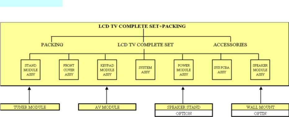
2. System Block Diagram
2.0 System Block Diagram (ME)
5

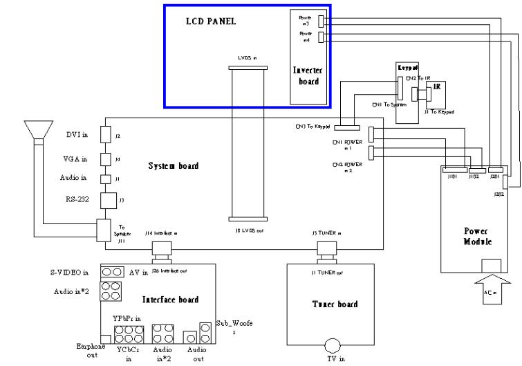
2.1 System Block Diagram (EE)
6
2.2 Connector Connection Diagram
7
2.3 Spare Parts List 2.3.1 EE parts list
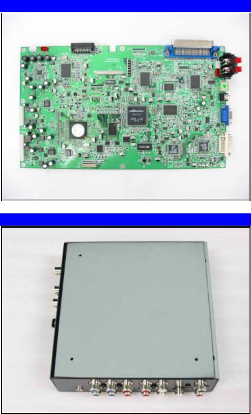
1. System Board for 27inch & 30inch
P/N: P061P3112011 for 27 P061P3112010 for 30
2. P311 Interface Module Assy
P/N: P70403820000
8
3. P311 Tuner Module Assy
P/N: P70403830000
4. PCBA Keypad
P/N: P061P3117010
9
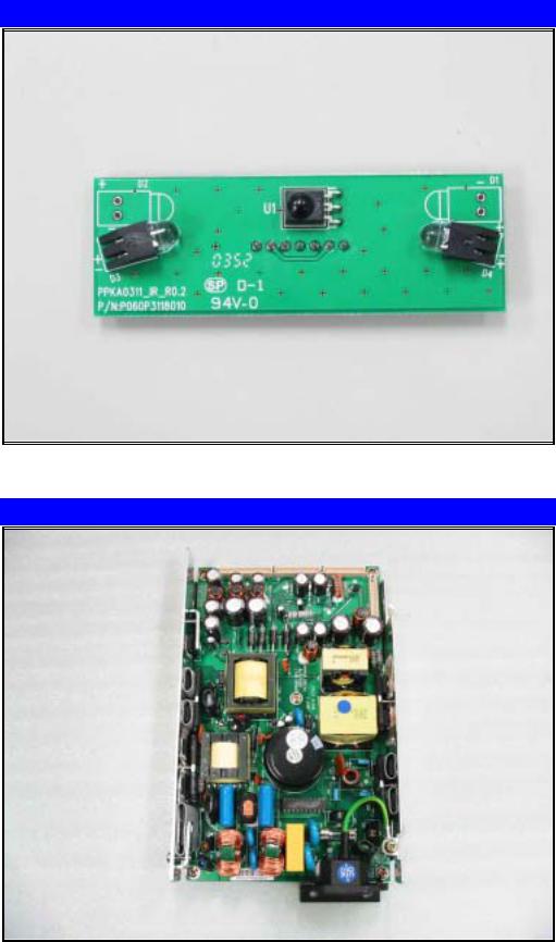
5. IR board
P/N: P061P3118010
6. Power Supply
P/N: P16000100000
10
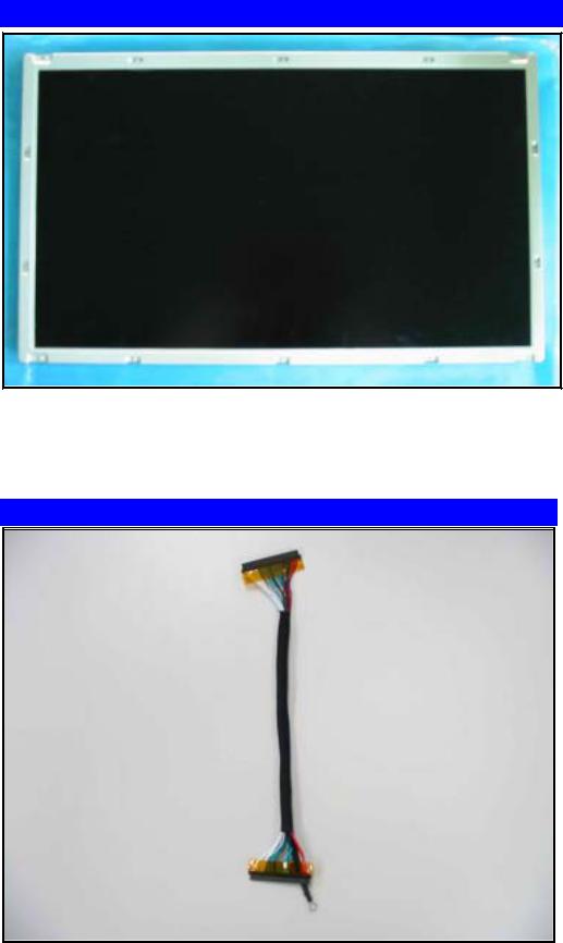
7. LCD Panel
P/N: P49000620000 for 27 P49000610000 for 30
8. System to Panel
P/N: P10W53000001
11
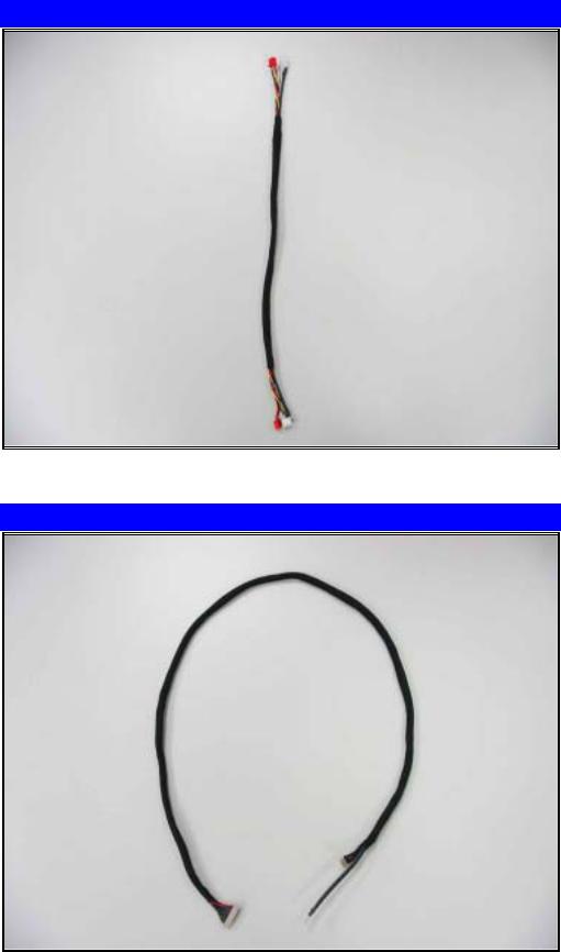
9. System to Speaker
P/N: P10W50600001
10. System to Keypad
P/N: P10W51500002
12
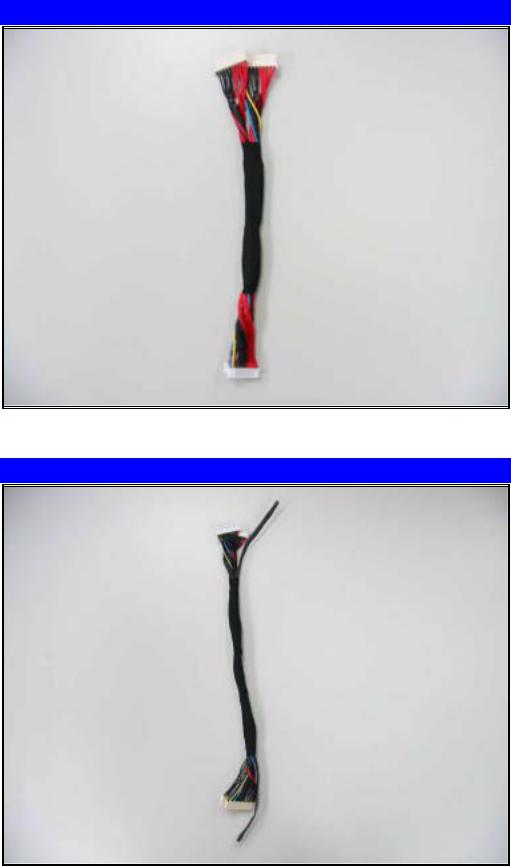
11. Power to Inverter
P/N: P10W62200001
12. System to Power
P/N: P10W62600001
13
2.3.2 ME parts list
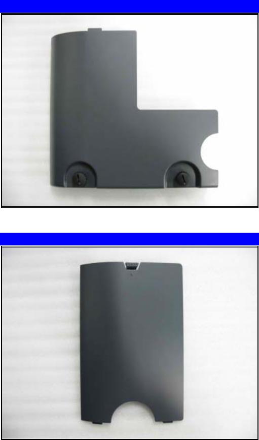
1. AV Cover Module Assy
P/N: P76000800000
2. Interface Cover
P/N: P60002040000
14
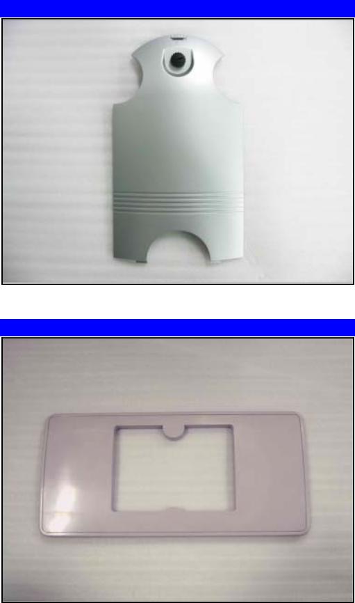
3. Conn fix Cover Module Assy
P/N: P76000800000
4. Foot Base Bottom
P/N: P60001981000
15
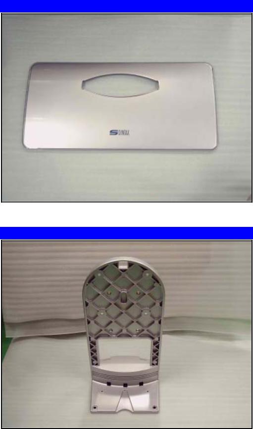
5. Foot Base Up
P/N: P60001980000
6. Al Vertical Support
P/N: P21001320000
16
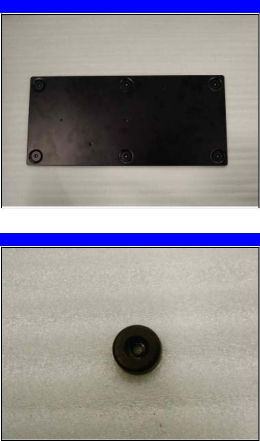
7. Foot Base Metal
P/N: P21001300000
8. Plastic Foot (GL-6)
P/N: P60001880000
17

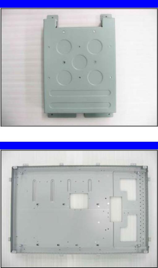
9. Keypad Assembly LCD TV
P/N: P76000790000
10. Speaker Module Assy
P/N: P76000750000
18
11. Speaker Foot Module Assy
P/N: P76000760000
12. Power Shielding Up
P/N: P21001360000
19
13. PCB-Support
P/N: P21001390000
14. PCB Support Metal
P/N: P21001380000 for 27 P21001390000 for 30
20
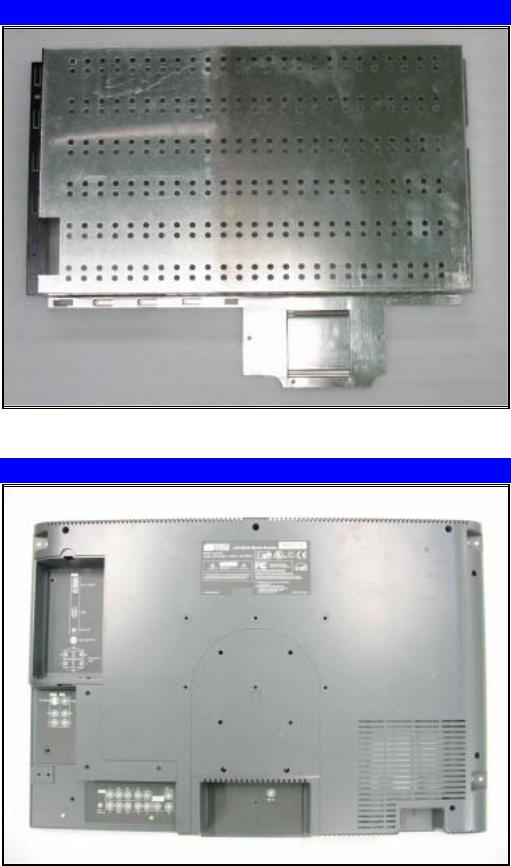
15. System PCB Shielding
P/N: P21001370000
16. Back Cover
P/N: P60001890000
21
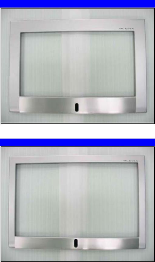
17. P311 27-Front Cover Assy
P/N: P70403850000
18. P311 30-Front Cover Assy
P/N: P70403860000
22
Loading...