

Page 1
Service Manual for
LT32HV & LT37HVE Models Ver. 1
"WARNING: This document contains confidential information, intended only for you,
and is privileged. This information is current and is subject to change. If you are not
the intended recipient, you are hereby notified that any disclosure, copying,
distribution, or any other use of this document is strictly prohibited. If you have
received this document by error, please notify us immediately by return email and
destroy the original document immediately and all copies thereof."
Page 2
Index
Getting Started__________________________________2
Models_________________________________________3
Preperation_____________________________________4
Part Replacment_________________________________5
Stand Removal/Replacment________________________6
AV Module Removal/Replacment___________________7
Right Side AV InputRemoval/Replacment____________8
TV Tuner Removal/Replacment____________________9
Removing Back Housing_________________________10
Exposed Back__________________________________12
Replacing AV Light_____________________________13
Replacing front IR/Keypad Board__________________14
Replacing front Olevia LED light__________________15
Exposing Mainboard for service or replacement______16
Replacing Left/Right Speakers____________________19
Replacing Power Supply_________________________21
1
Page 3

Getting Started
Tools Required –
• Magnetic Philips Head Screw Driver
• 3/16” Nut Driver
• Small Flat Head Screw Driver
• ESD Strap or equivalent
• Soft Terry Cloth towel
• Service Manual Instructions
Recommended Tool – Power Screw Driver
Safety Precautions –
• Read safety precautions thoroughly
• Keep the display away from high humidity
• Lay the display on a reliable flat surface with the
stand overhanging the edge before replacing parts
• Avoid spilling any liquid substances into the unit as it
may cause damage or electrical shock
• Do not leave this display unit with a storage temp.
above 140 degrees Fahrenheit (60 degrees Celsius), it
may damage the unit
• Unplug the power from the unit before performing any
type of part replacement
• Do not attempt to move or position the display unless
you are confident that you are able to successfully.
Avoiding this caution may result in bodily harm or
damage to the unit.
2
Page 4
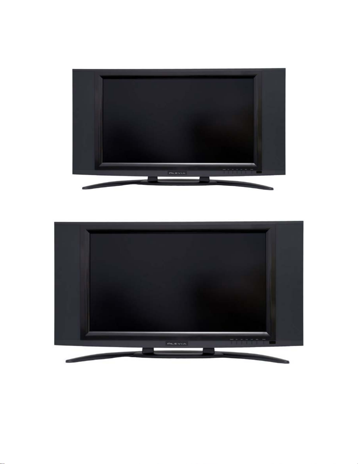
LT32HV
Models
LT37HVE
Note: The service instructions are applicable for both of
these models as they share identical components.
3
Page 5

Preparation
Important!
PLEASE PLACE LCDTV FACE DOWN ON NON-
ABRASIVE SURFACE.
Each Procedure is individually tailored for the component
you are replacing. Many components may be removed with
out removing everything else, read each procedure
carefully. All the procedures are aided with actual photos
of the components to help guide you.
It is recommended to place the display on a flat elevated
surface. This surface may be a clean and sturdy dining
room table, a desk or a bed. If the customer feels
comfortable with you servicing the display on the bed then
it is recommended to due so as most beds are usually soft
and non-abrasive.
Depending on the part you will be replacing, estimated
time should be anywhere between 10-40 minutes. If you
require advanced assistance you may contact Technical
Support (Mon-Fri, 9-6 PST). If support is required before
this specified time you may contact Product Development
from your provided contact list.
4
Page 6

Part Replacement
The following parts are the ones that you may have to
replace so please make sure you are properly prepared.
Parts –
• Stand
• AV Module
• Right Side AV Input
• Tuner Module
• Rear Housing
• IR/Keypad Board
• Mainboard
• Power Supply
• AV Light
• Speakers
• Olevia Front Blue LED light
5
Page 7
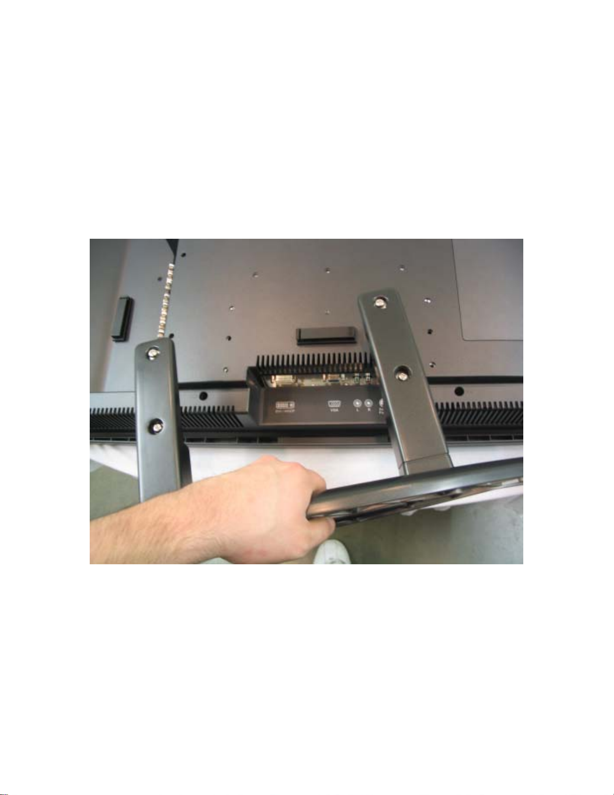
Stand Removal/Replacment
1. Unscrew the four silver screws from the stand. Follow
the opposite to mount the stand back to the display.
6
Page 8
AV Module Removal/Replacement
Removed
1. Unscrew the two (2) screws that secure the AV module
to the chassis.
2. Gently pull the AV module from the RCA jacks. You
may have to rock the module back and forth to
successfully free it and pull it out.
To re-insert the AV module slide in the casing and push
gently until you feel the module make contact with the
mainboard.
7
Page 9

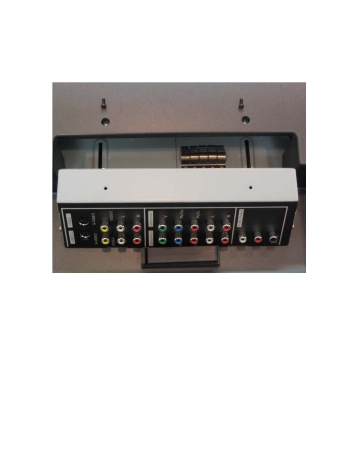
Right Side AV Input Removal/Replacment
1. Unscrew the two (2) screws that secure the side AV
input and pull out the screws.
2. Pull out the AV input and using a small flat head
screwdriver pry off the wire harness to the circuit
board.
Follow steps in reverse to re-insert the side AV input.
8
Page 10

TV Tuner Removal/Replacement
With Cover
1. Starting with the two (2) inner screws, unscrew all
four (4) that secure the Tuner module to the plastic
cover.
2. Remove the plastic tuner cover and gently slide out
the Tuner module.
To re-insert the Tuner module slide in the casing and
push gently until you feel the module make contact
with the mainboard.
9
Page 11

Removing Back Housing
Fully Assembled
1. Follow the above instructions of removing the
Stand, both the AV Module and Tuner modules
and the side AV input.
2. Once you have removed the above components
go around the edge of the housing looking for the
indication arrows of which screws to remove. The
arrows will look like this…
10
Page 12

3. Remove ten (10) screws from these indicated
locations.
4. There are two (2) other screws located by the AV
and Tuner Modules that have to be removed.
5. With all twelve (12) screws removed pull up on the back
cover to remove.
11
Page 13

Exposed Back
W/ Stand/Wall mount bracket over the mainboard
Exposed you will find that the left and right speakers, the
power supply, the mainboard, the IR pad and the AV light
are easily accessible.
Make note that in order to access the mainboard you must
remove the stand/wallmount bracket by removing the five
(5) screws that secure it to the panel chassis. It’s also
important that when re-mounting the stand/wallmount
bracket to make sure it is securely tightened since all the
weight of the display rests by this piece of metal.
12
Page 14

Replacing AV Light
1. Follow the above instructions of removing the Stand,
the AV and Tuner Modules, the side AV inputs and the
back cover.
2. Remove the red and black colored wire from the
circuit board.
3. Unscrew the two (2) screws on each side of the circuit
board and pull out the AV light.
Repeat steps in reverse order to place the replacement
AV light and assemble the unit.
13
Page 15

Replacing front IR/Keypad board
1. Follow the above instructions of removing the
Stand, the AV and Tuner Modules, the side AV
inputs and the back cover.
2. Remove the two (2) wiring harnesses that are
connected to the IR/Keypad circuit board.
3. Unscrew the five (5) screws that secure the
IR/Keypad to the front bezel.
Repeat steps in reverse order to place the replacement
IR/Keypad and reassemble the unit.
14
Page 16

Replacing front Olevia LED light
Brown circuit board is the Olevia LED Light
1. Follow the above instructions of removing the
Stand, the AV and Tuner Modules, the side AV
inputs and the back cover.
2. Remove the one (1) red and black wiring harness.
3. Unscrew the two (2) screws securing the Olevia
LED board. You should then be able to slide out the
Olevia LED board and position the replacement.
Repeat steps in reverse order to place the replacement
front Olevia LED Light board and assemble the unit.
15
Page 17

Exposing Mainboard for service or
replacement
16
Page 18

You will have to expose the mainboard to replace the
speakers, wiring harnesses or if the mainboard itself is
defective.
1. Follow the above instructions of removing the
Stand, the AV and Tuner Modules, the side AV
inputs and the back cover.
Note: You will also have to remove the
stand/wallmount bracket in order to gain access to
the mainboard cover.
2. Remove the six (6) mainboard cover screws that
surround the cover.
3. Push down (towards you) on the cover then start
lifting it off the chassis. You will have to pull the
edges of the cover where the modules connect to
the mainboard in order to clear the mainboard.
You may also require pulling apart the lower left
corner to pull the wiring harness through. The
mainboard should now be exposed.
Removing/Replacing mainboard
1. First follow above steps.
2. Carefully pull of all wiring harnesses from the
mainboard to all surrounding components. Take
extra precaution when removing the signal wire
that is coming from the panel to the mainboard
as it very fragile.
Note: Do not remove the signal wire from the Panel
(inverter board) itself.
17
Page 19

Signal wire W/ ground from panel
3. Remove the six (6) screws that secure the
mainboard down to the panel chassis (starting
with the ones with the ground wires).
4. Lift the mainboard out and replace with the new
mainboard.
Repeat steps in reverse order to place the new
mainboard on the Panel chassis and reassemble the unit.
18
Page 20

Replacing Left/Right Speakers
Right Speaker (sideways view)
Left Speaker (sideway view)
1. Follow the above instructions of removing the
Stand, the AV and Tuner Modules, the side AV
inputs and the back cover.
19
Page 21

Note: You will also have to remove the
stand/wallmount bracket in order to gain access to the
mainboard cover.
Note: You will also be required to remove the
mainboard cover to gain access to the mainboard
itself.
2. Open the following couplers using a small flat
head screwdriver.
3. From the mainboard disconnect the speaker wire
harness for the speaker you are replacing.
4. Unscrew the four (4) screws that secure the speaker
to the front bezel. Two on top and two on bottom.
5. Lift out the speaker and replace with the new
speaker.
Repeat steps in reverse order to replace the speaker and
reassemble the unit.
20
Page 22

Replacing Power Supply
1. Follow the above instructions of removing the
Stand, the AV and Tuner Modules, the side AV
inputs and the back cover.
2. Disconnect the three (3) wiring harnesses that are
exposed on the outside of the power supply.
3. There are six (6) screws that have to be removed to
get the cover off the power supply to access the
forth wiring harness. Review the following pictures
to learn their locations.
21
Page 23

Two (2) screws at lower left and upper right
These two (2) screws
Two (2) screws at upper left and right corners
4. Once you have removed the six (6) screws from the
cover of the power supply you may now pull up and back
towards the power inlet to pull off the power supply
cover. The fourth wiring harness should be accessible.
22
Page 24

Note: There are two (2) small notches on the bottom side of
the power supply cover. You will have to either rock the
cover side to side or pry it out gently while moving it up
and down to pull it off completely.
23
Page 25

5. Disconnect the wiring harness from the lower
left side of the power supply as shown in the above
picture.
6. Remove the four (4) screws that secure the lower
power supply chassis to the panel chassis. This is
outside the casing of the power supply. You should
now be able to remove the power supply circuit board
and its lower chassis.
Repeat steps in reverse order to replace the new power
supply and reassemble the unit.
24
 Loading...