

Olevia 265T FHD User Manual
Table of Contents
Important Information
Important Safety Precautions
Introducing the OLEVIA TV
Accessories
TV Installation And Connection Guide
Identifying Front Controls and Rear Panels
- Descriptions of Connector Types
- Turn the power on the TV
Installation
- Connecting to an Antenna or Video Equipment with Antenna Outlet
- Connecting to a Set-T op-Box with HDMI Cables
- Connecting to a Satellite Receiver or Cable Box with Component Connectors
- Connecting to a DVD Player with A/V or S Video Cables
- Connecting to a DVD Player with Component Cables
- Connecting to a DVD Player with HDMI Cables
- Connecting to a Satellite Receiver or Cable Box with A/V Cables
- Connecting to a VCR, PVR, or DV with A/V Cables
- Connecting to a Blue-Ray DVD Player or HD-Receiver with HDMI Cables and a
PC with VGA Cables
- Connecting to a D-VHS with HDMI Cables
- Connecting to a D-VHS with Component Cables
- Connecting to an Audio Receiver
- Connecting to a Home Theater System or Earphone Set
- Instruction for Uploading New Firmware
Remote Control Guide
Remote Function Keys & Description
Programming the Remote Control
Battery Installation
On Screen Display (OSD)
Introduction
Operating in the OSD
Initial Screen
PICTURE OSD Adjusting TV Picture Settings
- Description of Settings
- Selecting the Picture Mode
- Adjusting the Picture Quality
AUDIO OSD Adjusting Sound Quality
- Description of Settings
- Adjusting the Audio Settings
- MTS System for Stereo TV
SCREEN OSD Adjusting Screen Modes
- Description of Settings
- Changing the Screen Mode
- Selecting the Picture/Video Source
SETUP OSD Adjusting Personal TV Settings
- Description of Settings
- Searching the TV Channels
- Editing Channels
- Closed Caption Options
- Setting up Parental Control Password
- Activating the Parental Control Feature
- Resetting the Password
- Setting the Date and Time
- Setting the TV Timer
- Timeout Settings for OSD Menu
- TV OSD Languages
- Setting DPMS
- Setting LED Light
- Factory Default Option
- Displaying the Firmware Version
Specifications
Timing Mode for VGA and HDMI(PC)
Pixels Policy
Glossary
1
2
5
9
10
12
13
14
15
16
17
18
19
20
21
22
23
24
25
26
27
28
29
30
31
32
32
32
33
35
35
36
38
40
40
40
42
43
43
43
47
48
48
49
50
54
55
55
61
62
63
63
64
64
64
64
64
65
67
68
69
English
Important Information
Caution
Risk of electronic shock
Do not open
To reduce the risk of electronic shock, do not remove cover (or back).
Refer service to qualified Repair Technician or Repair Center.
No user-serviceable parts inside.
Read the following context indicated by the following symbol to the left. It indicates
important literature in operating the product.
English
Read the following context indicated by the following symbol to the left. It indicates
a potential high voltage hazard that may compromise your safety.
Caution
Take caution when moving the product on a cart. Quick stops, excessive force,
and uneven surfaces may cause the display unit and cart combination to overturn.
Caution
To prevent electric shock, match wide blade of plug to wide slot, fully insert.
Caution
This product satisfies FCC regulations when shielded cables and connectors are used to
connect the unit to other equipment. Prevent electromagnetic interference from electrical
appliances such as radios and televisions. Please use shielded cables and connectors for
connections.
Warning
FCC Regulations state that any unauthorized changes or modifications to this equipment
not expressly approved by the manufacturer could void the user's authority to operate this
equipment.
Caution
Make sure that the cable system is grounded to provide protection against voltage surges
and built up static charges.
Warning
THIS TELEVISION IS EXTREMELY HEAVY -- IMPROPER HANDLING AND INSTALLATION CAN RESULT IN
INJURY TO PEOPLE AND PROPERTY DAMAGE TO THE STRUCTURE AND SURROUNDING PERSONAL
PROPERTY! WALL MOUNTING OF THIS TELEVISION SHOULD ONLY BE ATTEMPTED BY A PROFESSIONAL
-- ANY LIABILITY FOR PERSONAL INJURY OR PROPERTY DAMAGE CAUSED BY FAILED WALL MOUNTING
ATTEMPTS WILL NOT BE ACCEPTED BY THE MANUFACTURER!
01
Important Safety Precautions
Cleaning
Remember to unplug the AC cord from the AC outlet
before cleaning the display unit.
Then spray small amount original WINDEX window
clearer (blue stuff), not Ammonia-added clearer, on
cloth to clean the display.
Remember to use only soft cotton cloth such as an old
100% cotton T-shirt, not sponges brillo abrasive
material, to clean the display.
No drips allowed.
Stand
Do not place the display unit on an unstable place.
The TV may fall resulting in serious personal
injuries to nearby people as well as damage to the
display unit.
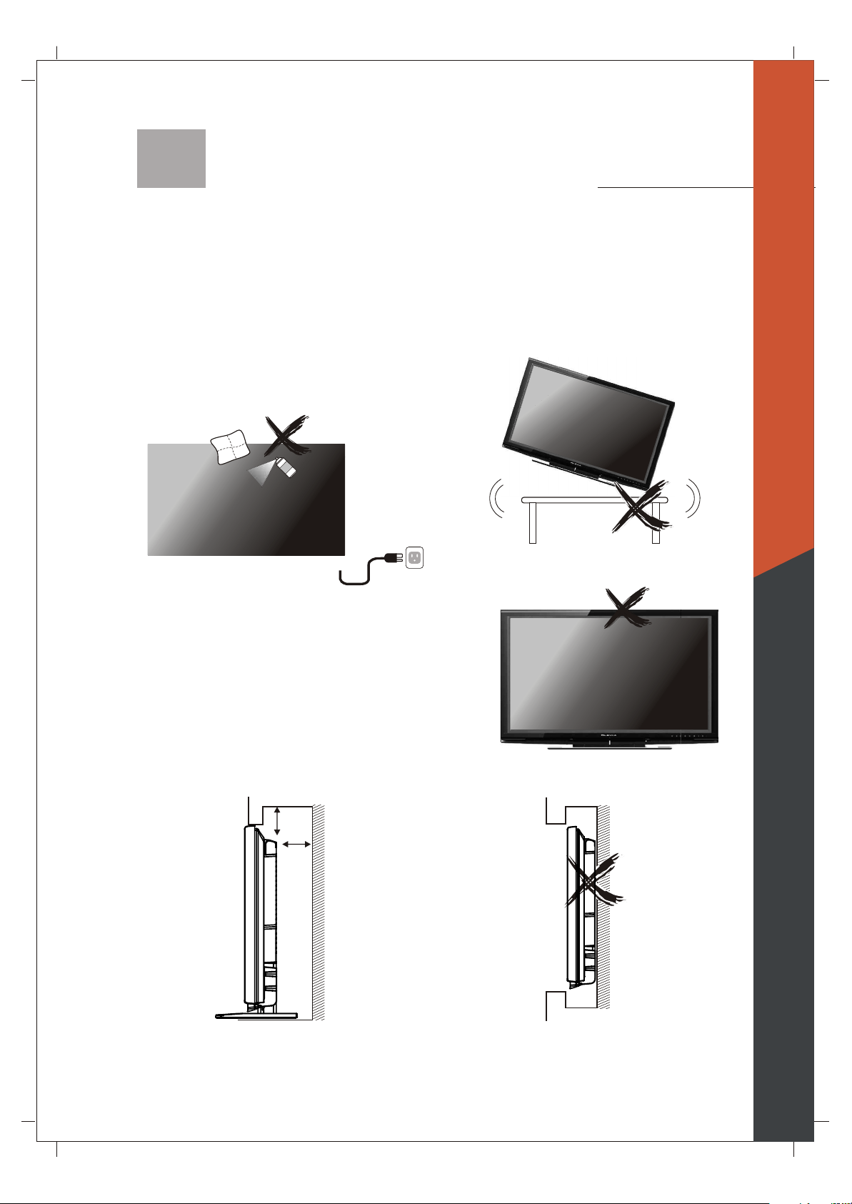
V entilation
Do not cover or block these vents and openings located
on the top and back of the display. Inadequate ventilation
may cause overheating and shorten the lifespan of the display.
Do not place in an enclosed area such as a built-in shelf,
unless proper ventilation is provided or the manufacturer's
instructions are followed. Keep the distance of 10cm
minimum between the display unit and wall. Never install the
display unit as indicated in the picture below.
English
Air circulation is blocked
10cm
10cm
Air circulation is blocked
02
Important Safety Precautions
English
Never insert objects or spill liquid
into the display unit
Never insert any object into the display unit through
openings or spill liquid on the display unit. High
voltage flows in the display unit, and inserting an
object can cause electric shock and/or short internal
parts.
Keep away from water and moisture
Do not place the display in areas where moisture is
present or where the unit may get wet such as bathrooms, kitchen, pool area or in a wet basement.
Keep away from heat sources
Keep the display unit away from heat sources such
as radiators, heaters, stoves and other
heat-generating products.
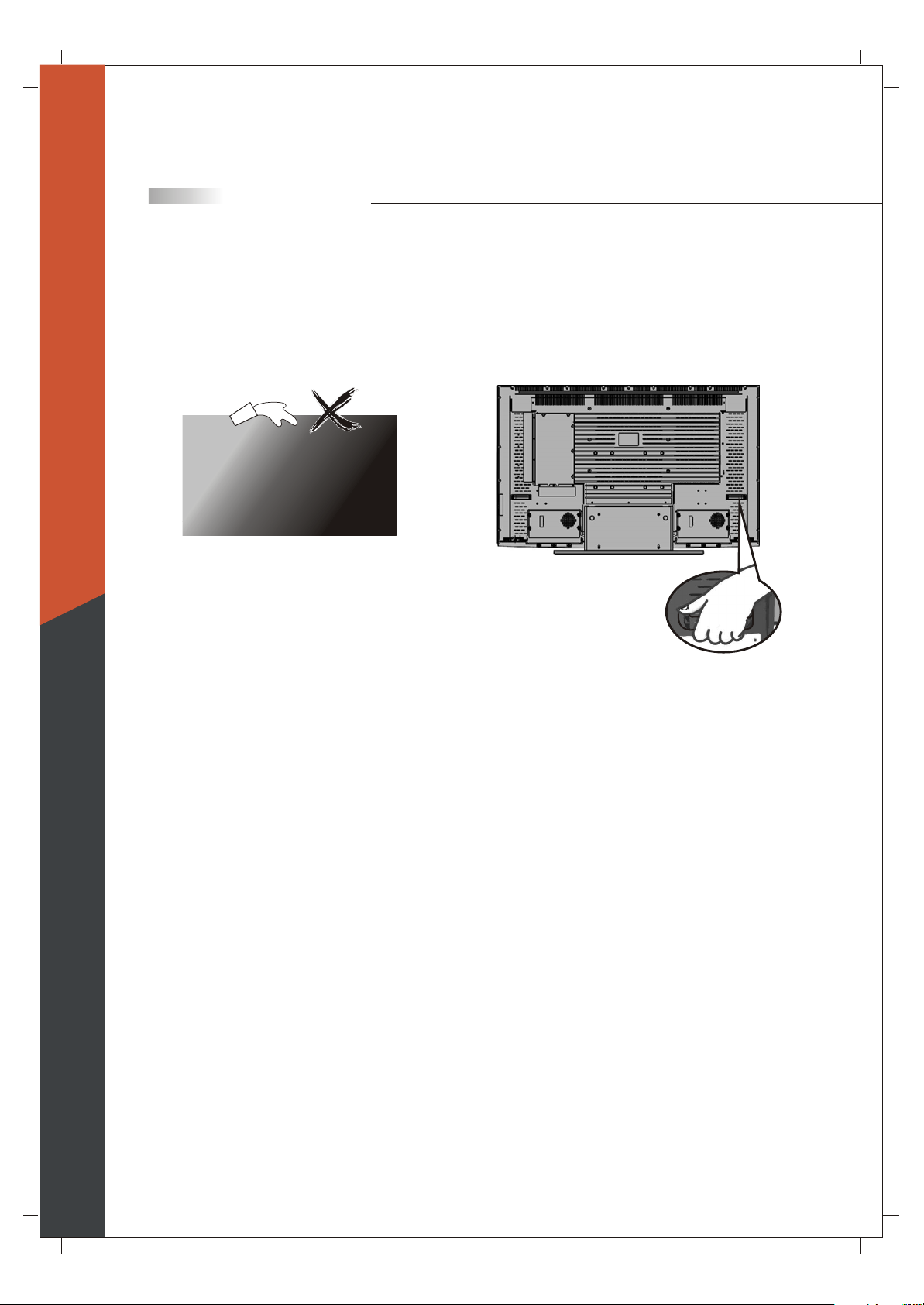
The liquid crystal panel used in this
product is made of glass
Do not hit the panel. Be careful to prevent from
getting hurt by broken glass pieces in case the panel
breaks.
Precautions when transporting the
display
Carrying the display requires two or more people.
Attachments
Do not use attachments not recommended by the
manufacturer. Use of inadequate attachments may
result in accidents to nearby poeple or to the unit.
Power source
This product must operate on a power source
specified on the specification label. If you are not
sure of the type of power supply used in your home,
consult your dealer or local power company. For
units designed to operate on batteries or another
power source, refer to the operating instructions.
Follow operating instructions
All operating instructions must be followed.
Servicing
Do not attempt to service the display unit yourself.
Removing covers expose you to high voltage and
other dangerous conditions. Request a qualified
service technician to perform the service.
AC cord protection
The AC cords must be routed properly to prevent
people from stepping on them or objects from resting
on them. Check the cords at the plugs and product.
Overloading
Do not overload AC outlets or extension cords. It
may result in electric shock or start a fire.
03
Important Safety Precautions
Replacement parts
In case the display unit needs replacement parts,
make sure that the service technician uses replacement
parts specified by the manufacturer, or those with
the same characteristics and performance as the
original parts. Use of unauthorized parts can result
in fire, electric shock and/or other danger.
Safety checks
Upon completion of service or maintenance, request
the service technician to perform safety checks to
ensure that the display unit is in proper operating
condition.
Repair
When the display unit displays an abnormal
condition, any noticeable abnormality in the display
unit indicates that the display unit needs servicing.
If any of the following conditions occurs, unplug
the AC cord from the AC outlet, and request a
qualified service person to perform repairs.
1.A liquid was spilled on the display unit or objects
have fallen into the display unit.
2.The display unit has been exposed to rain or water.
3.The display unit has been dropped or damaged.
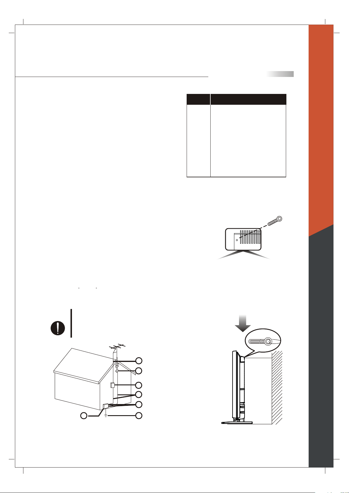
Reference
Grounding component
Electric service equipment
1
Power service grounding electrode
2
system (NEC Art 250. Part H)
Ground clamps
3
Grounding conductors (NEC Section
4
810-21)
Antenna discharge unit (NEC Section
5
810-20)
Grounding clamp
6
Antenna lead-in wire
7
Prevent the display unit from falling
Please select the fit-sized screws and wire ropes to fasten
the display unit on the wall to prevent it from falling
immediately when the earthquake happens.
English
Environment
The display unit only operates within the
temperature 0 C to 40 C.Operation outside of the
recommended may cause damage to your product.
Warning
When installing or realigning an
outside antenna system, extreme
care should be taken to keep from
touching such power lines or circuits.
Contact with them could be fatal.
77
66
55
44
33
11
22
Antenna and satellite grounding
04

Introducing the OLEVIA TV
Welcome!
Thank you for purchasing a OLEVIA LCD HDTV.
This manual is to be used with the following model:
OLEVIA 2 Series
This manual is designed to help you through setting up and operating your
LCD HDTV as quickly as possible. The model and serial numbers are on the
back cover of your TV. Write these numbers in the space provided in this
manual for your records. Please read all the safety and operating instructions
carefully, and keep this manual for future reference.
Licensed Under U.S. Patent 4930160.
English
Owner's Record
The model and serial numbers are located at the rear of the display unit, or
on the side of the media receiver unit on the cartons (white label). Record
these numbers in the spaces provided below. And r
www.olevia.com.
Corporation or local dealer regarding this product.
Model No.
Serial No.
Refer to them whenever you call Syntax-Brillian
egister your product at
05

Introducing the Olevia TV
OLEVIA LCD HDTV includes many features, you will enjoy throughout
the usage of your TV. These highlighted features include:
Fully Integrated HDTV (High Definition TV):
HDTV delivers a stunning picture far beyond the quality of standard
televisions. These programs offer crystal clear video with amazing
detail played with enhanced audio quality of digital television programs.
You can enjoy better sound and picture in movies, prime time TV shows,
and other HD broadcasts in dynamic television settings through cable,
satellite or even free broadcasts over the air.
HDMI (High Definition Multimedia Interface):
The next generation of DVI, HDMI provides the best interface between
a DVD player and compatible products such as digital set top box for
uncompressed digital audio/video connections. When matched with a
SyntaxBrillian OLEVIA TV, multi-channel digital audio signals,
uncompressed DVI digital video and intercommunication between high
multimedia interfaces are combined through a single interconnecting cable.
English
HDMI and the HDMI logo are trademarks or registered trademarks of
HDMI Licensing, LLC.
Manufactured under license from Dolby Laboratories. Dolby and the
double-D symbol are registered trademarks of Dolby Laboratories.
Olevia and the Olevia logo are trademarks or registered trademarks of
Syntax-Brillian Corporation in the United States and other countries.
Corporate names, trademarks, registered trademarks, service marks,
symbols, and logos stated herein are property of their respective companies.
06

English
Introducing the Olevia TV
Technology Overview
Congratulations! You've just purchased the most advanced video processing
Television System available today. HQV represents an enormous leap in
video processing performance with true flagship de-interlacing, cadence
detection, noise reduction and scaling. Silicon Optix designed the HQV
processing engine as a no-compromise solution.
The roots of Silicon Optix HQV processing go back to the early 1980s, when
Lockheed Martin developed it for military image and video processing.
In the 15+ years of development by Lockheed Martin, over $100 million
was invested in the technology.
Teranex was founded in 1998 to commercialize the Lockheed Martin technology.
Teranex's video-processing boxes sell for as much as $100,000 and are used
by the leading broadcasters around the world, including NBC, CBS, ABC,
FOX, and Warner Brothers.
In 2002, Silicon Optix and Teranex realized that semiconductor technology
had advanced enough that they could take the large Teranex video-processing
box and condense into an affordable single chip. In September 2004, the
Realta HQV video processor, which matches the performance of Teranex's
$60,000 video processor, was announced to the world.
HQV De-interlacing
HQV is a true pixel-based motion adaptive approach in which maximum
resolution is preserved. When both fields reach the HQV video processor,
a comparison is made with the previous two fields to determine which pixels
represent motion. HQV processing is careful to discard and interpolate only
the pixels that are necessary.
To recover some of the detail lost in the areas in motion, HQV processing
implements a second stage Multi-Direction Diagonal Filter that is able to
reconstruct some of the lost data by identifying edges of moving objects
resulting in smoother images more faithful to the original.
HQV Film Cadencing and Video/Film Detection
While the 2:3 cadence is the most common format used, it is only one of 8
cadences that are in use. Other cadences are necessary for other frame rates.
The range is wide, with animation being as low as 8 fps and documentaries
being as high as 30 fps.
Most competing video processors only look for a 2:3 pattern, and thereby
ignore all of the other cadences in use. HQV's flagship cadence detection
technology does not simply match incoming video against pre-programmed
patterns, but identifies frames simply as they arrive. This means that not
only is HQV processing able to detect all the cadences currently in use, no
matter how uncommon, but it will also be able to detect cadences that have
not yet been invented.
No matter what type of video you're watching or where it comes from, HQV
processing will always provide the best image.
07

Introducing the Olevia TV
Detail Enhancement
HQV Detail Enhancement avoids halo or ringing artifacts at even the
highest setting. A key benefit of HQV Detail Enhancement is that, when
used in conjunction with our 1024-tap scaler, standard-definition TV
can be delivered at near high-definition quality.
1024-tap scaling
HQV processing uses a scaler with an unprecedented 1024 taps. This level
of quality reflects the fact that HQV processing has its roots in Teranex
algorithms, which were developed for defense and military image analysis.
For every pixel, the HQV processor evaluates the surrounding 1024 pixels
in order to provide the best image quality when scaling the image up from
standard definition.
10-bit 4:4:4 internal data paths
Not only does HQV processing implement some of the most advanced
algorithms for video processing, but the internal data paths support 10-bitsper-channel with full 4:4:4 color sampling. The term "4:4:4" refers to the
fact that the color information can be input at full horizontal resolution, and
10-bit data paths provide 1024 steps of brightness and color. Simply put, by
maintaining more bits in the data, HQV products can preserve all the fine
detail and dynamic range found in the original source.
Summary
Realta HQV -- the trillion operations per second video processing engine
proven on the front lines of Hollywood is finally available for your home.
No matter what your source or your display, HQV processing lets you
experience all the pixels as they were meant to be seen.
English
08
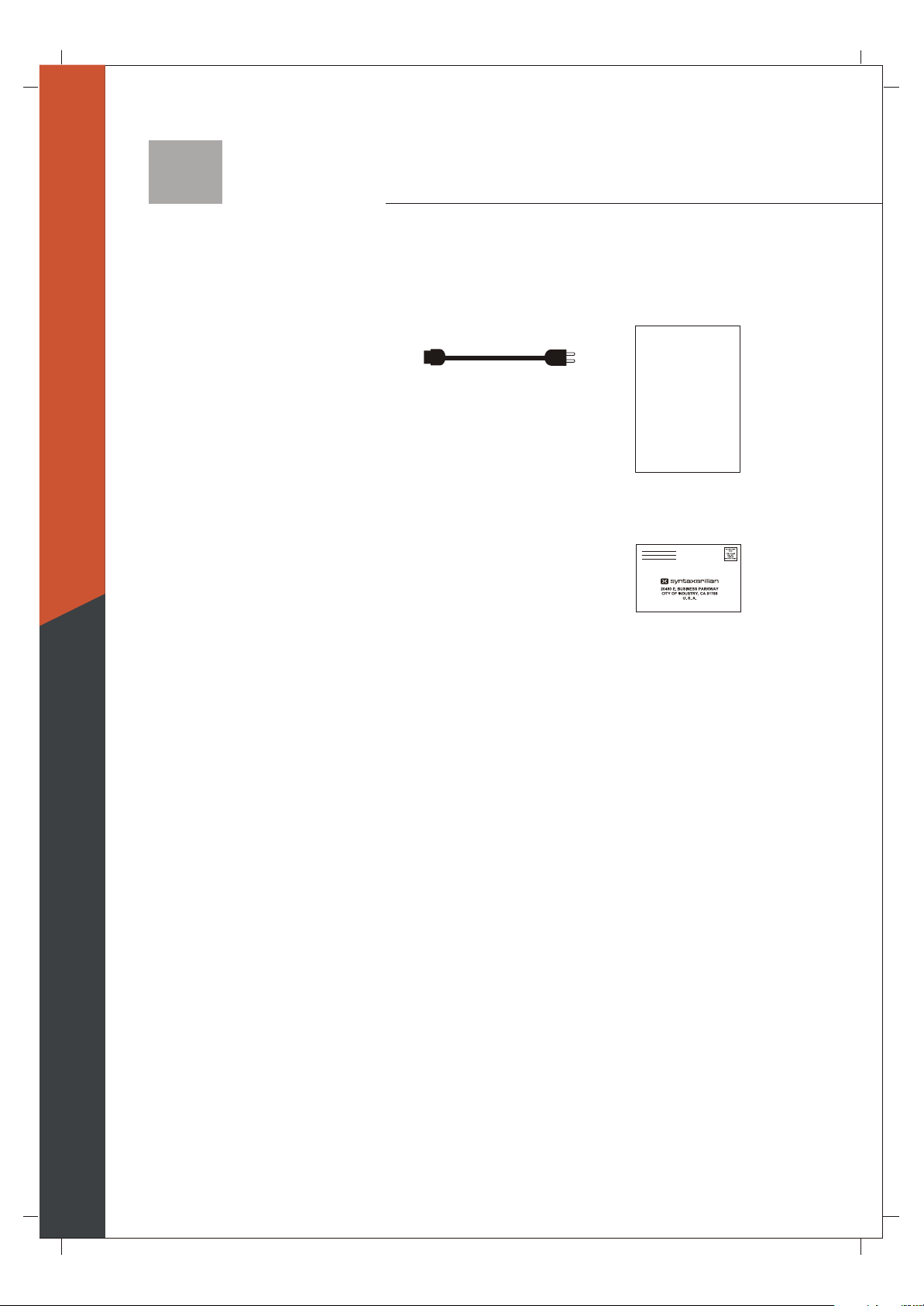
Accessories
Supplied Accessories
English
Remote control & batteries (AAA x 2)
Power cord x 1 User manual x1
QSG x 1
These items are all you need to set up and operate the TV in its
basic configuration.
Warranty Card x 1
Note: Most components (VCRs, DVD players, etc.) come with
the necessary cables to connect them. If you want to set up a
complex system, you may need to buy extra cables, connectors,
etc. Be sure to have these on hand before you start to connect
your system.
09
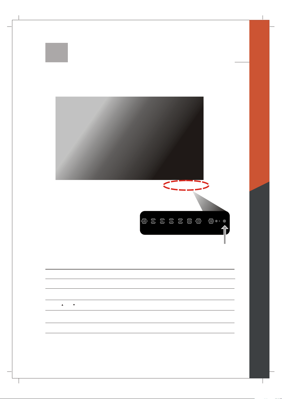
TV Installation and Connection Guide
Identifying Front and Rear Panels
Front Panel
English
IR SENSOR
POWER
ENTER
MENU
CH / CH
VOL+/VOL-
SOURCE
IR Sensor
Contains Infra-red light for digital data transmission by the remote control. Please
point remote control at IR Sensor for function.
Turns display on/off.
Press to enter to Sub-Menu, or select and confirm your setting.
Displays the On Screen Display(OSD) menu. In OSD menu, press it to return to the
previous screen or to exit.
Adjusts Channel. In the OSD menu, both keys are used to navigate within menu.
Adjusts Volume. In the OSD menu, both keys are used to navigate within menu.
Vol+ is used to select the highlighted option.
Press to switch the input sources.
10
English
TV Installation and Connection Guide
Identifying Front and Rear Panels
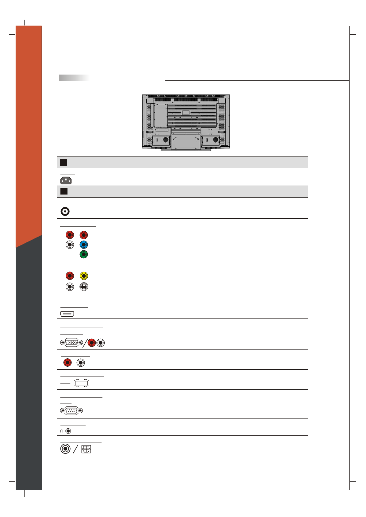
Rear Panel
1
Power Connections
AC In
2
Computer / TV Signal Connections
RF Terminal
The power cord connects here.
To receive signals from VHF / UHF antennas or a cable system
(For TV Models Only)
Component 1/2
R
L
Pr/Cr
Pb/Cb
Y
Video 1/2
R
L
AV
S-Video
HDMI/DVI
VGA/Audio Input
(PC) Port
L
R
Audio Input
L
R
Firmware Upgrade
Port
RS232C Control
Port
(5 RCA jacks) Used to connect A/V equipment with component video outputs, such as
a DVD player, Digital Satellite Receiver, or compatible Video Game System.
NOTE: The component inputs have a superior quality of picture than the S-Video or AV
(composite video) inputs.
AV (Composite Video: 3 RCA jacks): Used to connect a VCR, Super VHS (S-VHS),
DVD player, or other video devices to the TV.
OR
S-Video : (1 DIN and 2 RCA jacks) Used to connect video devices to the TV.
However, they have a better quality of picture than a composite video signal.
Used to connect digital video equipment with a HDMI/DVI output.
NOTE: Preferred connection for HDMI/DVI Satellite or Set-Top-Box equipment.
Used for analog RGB signals from a personal computer. VGA has one set of Audio R/L inputs.
OR
As a computer input with VGA to RCA Adapter.
To send an AV receiver or other equipment's connected audio signals to the TV
To allow firmware upgrades.
Used to control the TV with automation devices.
Earphone
Coaxial/Optical
Used for audio output to earphone.
To send the TV's connected digital audio signals to an AV receiver or other equipment, such as
the amplifier
11
TV Installation and Connection Guide
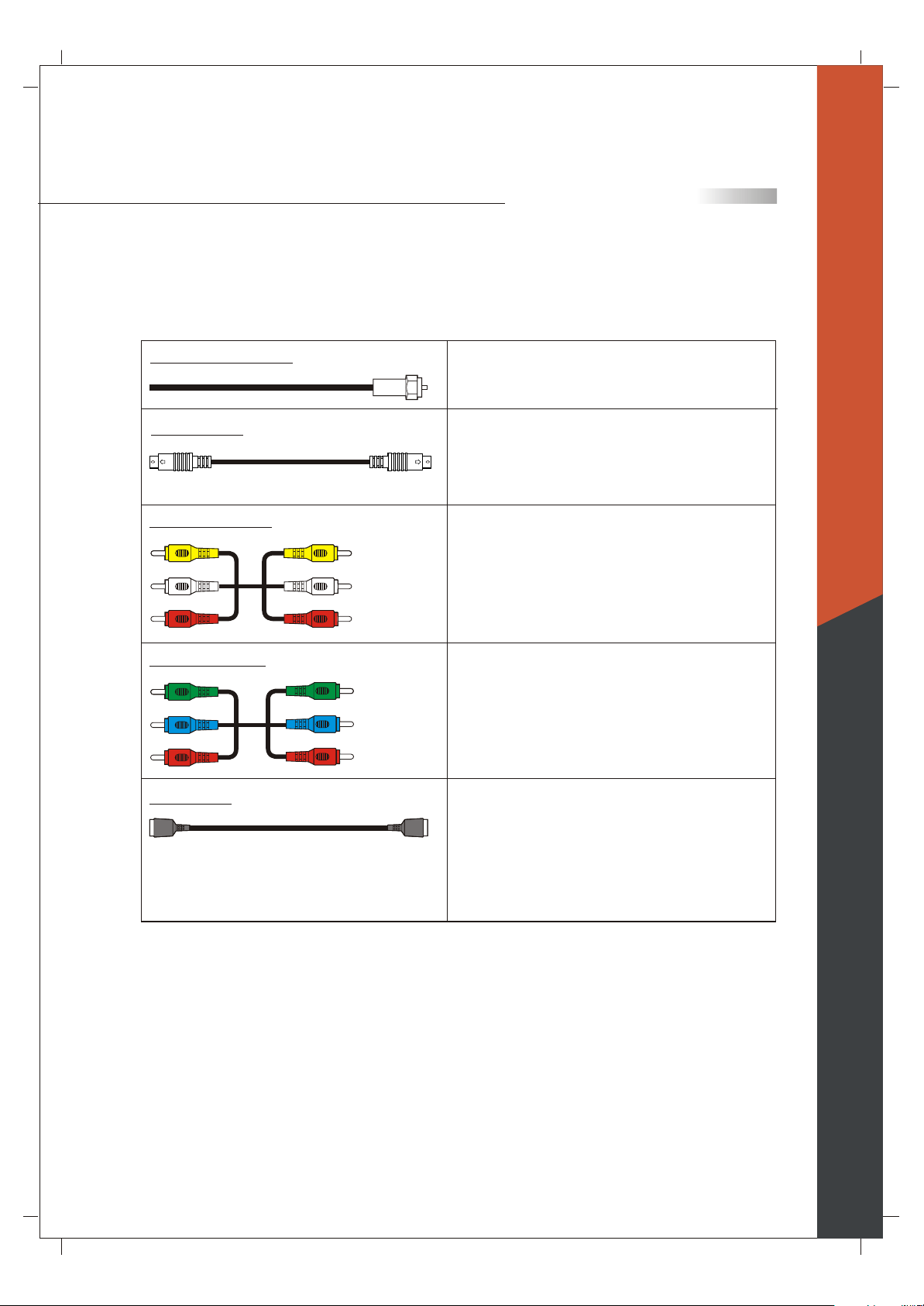
Descriptions of Connector Types
You may find it necessary to use some of the following cable types during setup.
75-ohm Coaxial Cable
S-Video Cable
Audio/Video Cable
Component Cable
HDMI Cable
Video (Yellow)
Left Audio (White)
Right Audio (Red)
Y (Green)
Pb/Cb (Blue)
Pr/Cr (Red)
For TV/cable connection
Used for transferring video signal, which is split
into two signals, brightness and color.
Through this connection, you can view a better
picture than AV (Composite Video) connection.
Used for transferring audio and video signal.
This connection is the most commonly found on
A/V equipment.
Used for transferring video signal, which is split
into three signals, one brightness and two color.
Through this connection, you can view a better
high definition picture than S-Video or AV
(Composite Video) connection.
Used for
transferring digital uncompressed video
and audio signals to the TV.
HDMI signal is purely digital and provides a
crystal clear technology better than component,
S-Video or Video connections. It is strongly
recommended to use this connection if you have
this function on your equipment.
English
12
English
TV Installation and Connection Guide
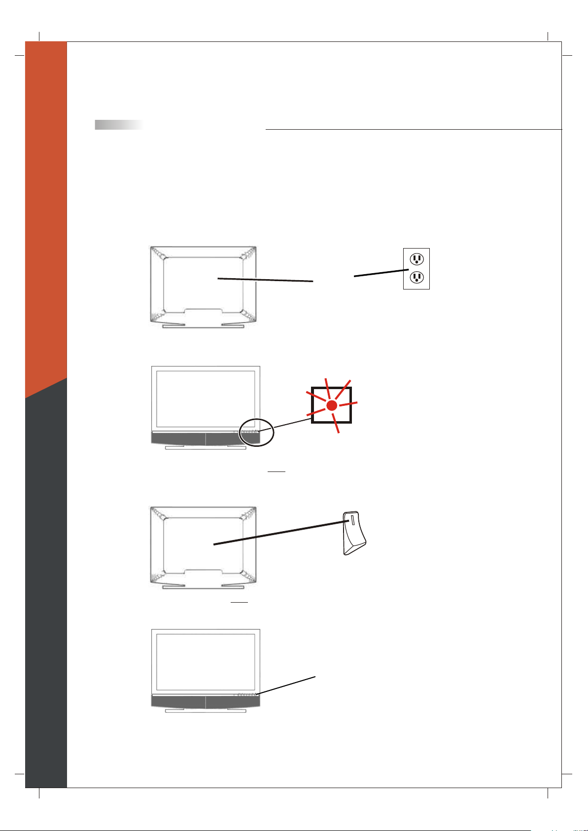
Turn the power on the TV
Please f ollow these steps to turn the power on to the TV.
1) Before connecting the Power cord, make sure all other connections are done first.
2) Connect the Power Cord from a Wall Outlet to the Power IN Port on the back of the TV as shown below.
Back of TV
Power
IN Port
A red or blue light on the front of the TV may turn on. If so, then skip step 3 and step 4. If the light is NOT
on, do Step 3.
Power
Cord
Wall
Outlet
Front of TV
3) If a red or blue light on the front of the TV is NOT on, press the Power Button on the back of the TV as
shown below. Now the light on the front turns on. In other words, the Power Button in the back must be
on for the light in the front to turn on.
Back of TV
4) Press the POWER Button on the front of the TV as shown below or on the remote control. Wait about
10 seconds for something to appear on-screen. Your TV is on and the red or blue light on the front turns
off automatically.
Front of TV
POWER Button
Red or blue light
(also called "standby light").
Color and location depends on mode
POWER Button
(also called"master power switch")
13

TV Installation and Connection Guide
Installation
In the following pages, you will find directions on how to install your tv and choice of video equipment.
The next few pages show examples of how to connect to video inputs on your Olevia TV. For more detailed
information, see the user manual that came with your video equipment.
Connecting to an Antenna or Video Equipment with Antenna outlet
Connecting to a Set-Top-Box with HDMI Cables (Preferred TV connection)
Connecting to a Satellite Receiver or Cable Box with Component Connectors
(Secondary Preferred after HDMI)
Connecting to a DVD Player with A/V or S Video Cables
Connecting to a DVD Player with Component Cables
Connecting to a DVD Player with HDMI Cables
Connecting to a Satellite Receiver or Cable Box with A/V Cables
Connecting to a VCR, PVR, or DV with A/V Cables
Connecting to a Blue-Ray DVD Player or HD-Receiver with HDMI Cables
and a PC with VGA Cables
Connecting to a D-VHS with HDMI Cables
Connecting to a D-VHS with Component Cables
Connecting to an Audio Receiver
Connecting to a Home Theater System or Earphone Set
Instruction for Uploading New Firmware
English
14
English
TV Installation and Connection Guide
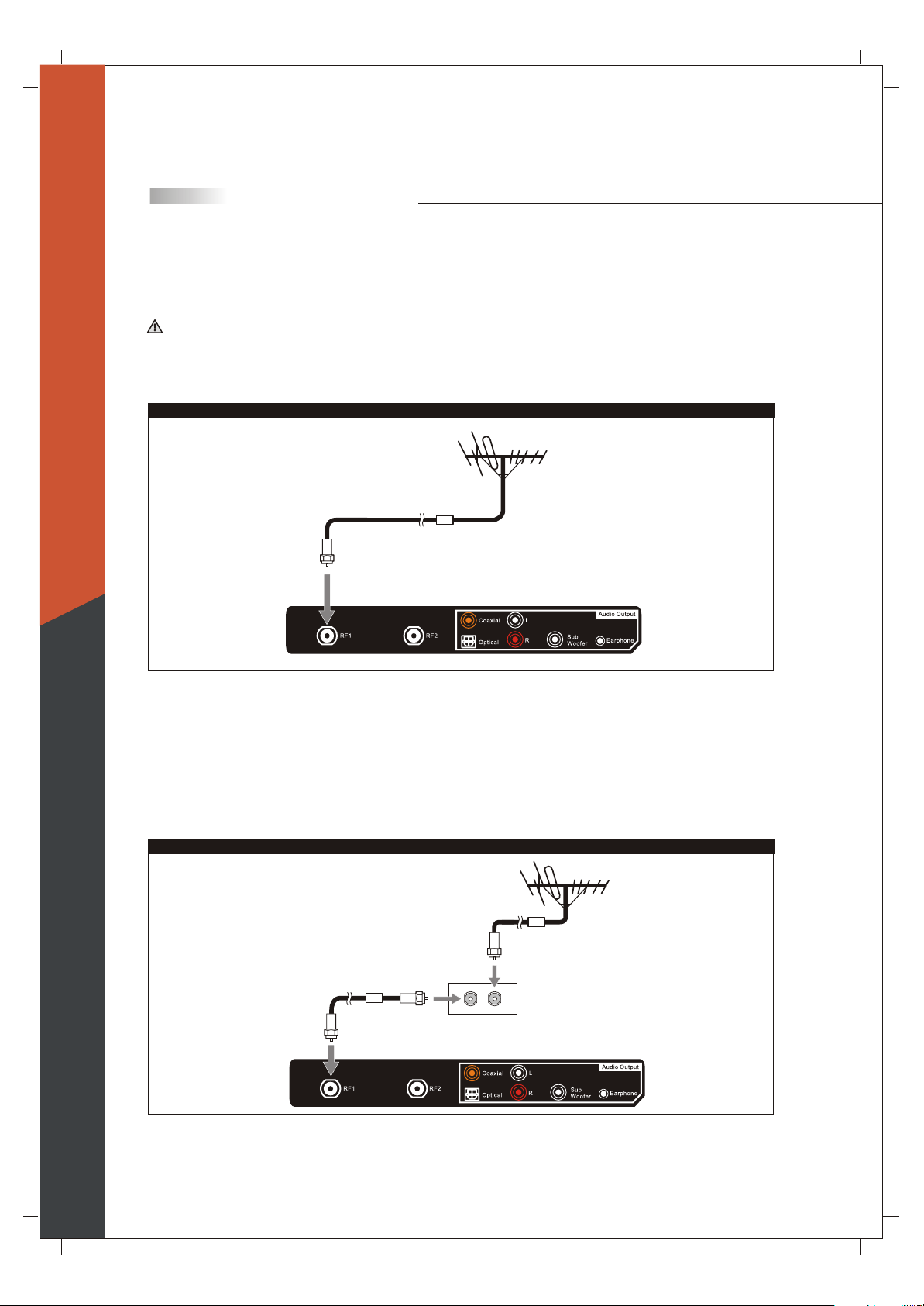
Connecting to an Antenna or Video Equipment with Antenna outlet
(For TV and DTV Source)
Disconnect all power sources before making any connection.
1. Connect a 75-ohm coaxial cable (or choice of Antenna Cable) from your cable or antenna to the TV's
Antenna jack (RF Terminal).
For 265 TFHD Model
(75-ohm coaxial cable)
Rear of TV
If connecting to Video Equipment with Antenna outlet
1. Connect a 75-ohm coaxial cable (or choice of Antenna Cable) from your cable or antenna to the Video
Equipment's IN jack.
2. Connect another 75-ohm coaxial cable from the Video Equipment's OUT jacks to the TV's Antenna jacks
(RF Terminal).
For 265 TFHD Model
(75-ohm
coaxial
cable)
(75-ohm coaxial cable)
OUT
jack
(Video Equipment
with Antenna In/Out
Socket)
IN
jack
Rear of TV
15
HDMI 1
R L
HDMI 2
R
L
VGA /
Component 3
RS232C
Control Port
R
L
Firmware
Upgrade Port
TV Installation and Connection Guide
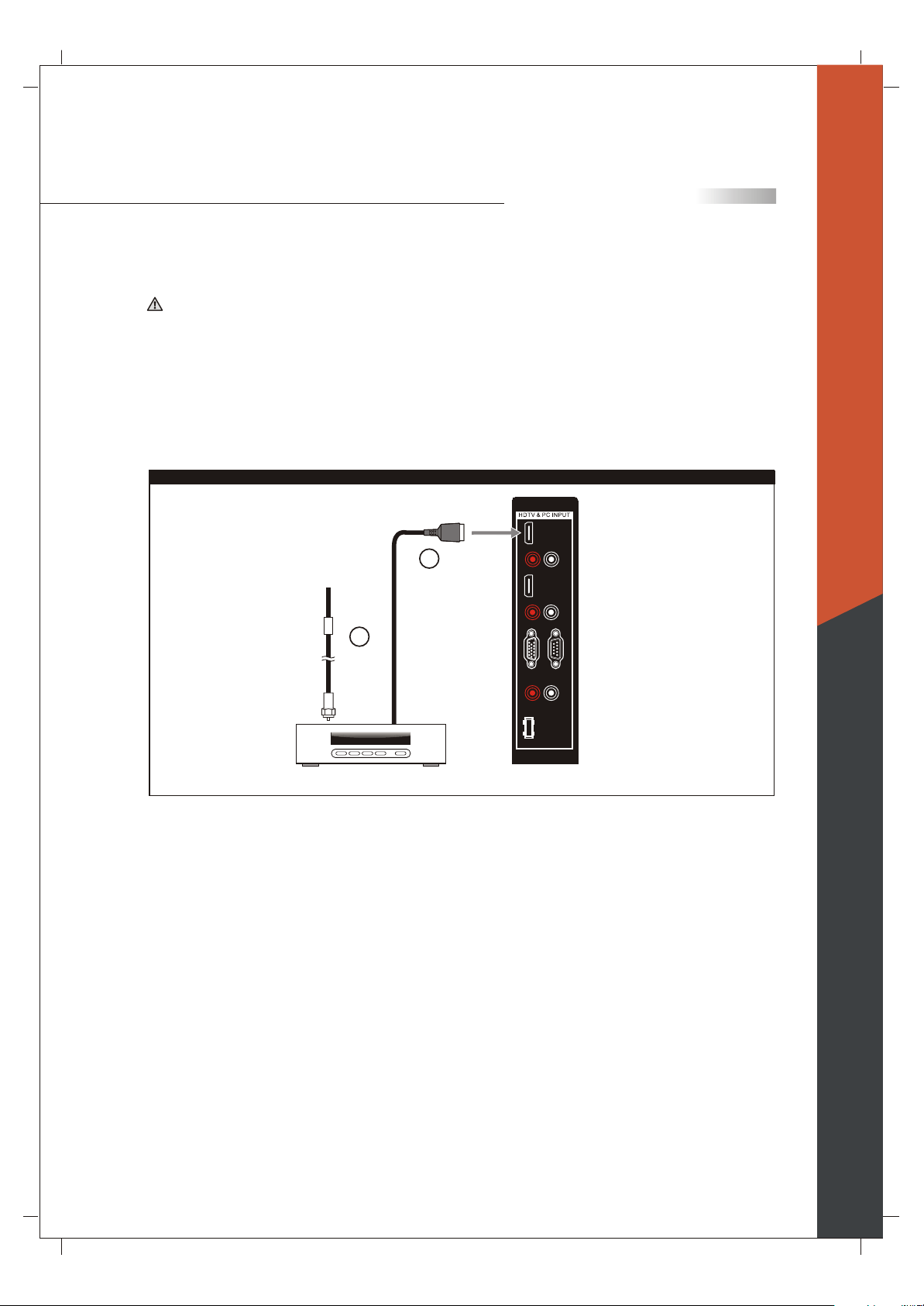
Connecting to a Set-Top-Box with HDMI Cables (Pr eferr ed TV connection)
Disconnect all power sources before making any connection.
1. Connect a 75-ohm coaxial cable (or choice of Antenna Cable) from your cable or antenna to the
Set-Top-Box's Antenna jack (RF Terminal).
2. Connect a HDMI cable from the Set-Top-Box's HDMI OUT jacks to the TV's HDMI IN jacks.
For 265 TFHD Model
Rear of TV
Cable/ Satellite
2
HDMI cable
1
(75-ohm
coaxial
cable)
Set-Top-Box
Note: HDCP is a copy protected digital connection that receives analog or digital video and audio signals from
equipment with a HDMI output that features the HDCP function. HDMI allows the transfer of digital
uncompressed data to the TV. This connection is superior when compared to the Component, S Video or AV
(composite) connections.
English
Note: HDMI signal is purely digital and provides a better picture, it is better than component, S-Video or
Video connections. It is strongly recommended to use this connection if you have this function on your
equipment.
16

HDMI 1
R L
HDMI 2
R
L
VGA /
Component 3
RS232C
Control Port
R
L
Firmware
Upgrade Port
English
TV Installation and Connection Guide
Connecting to a Satellite Receiver or Cable Box with Component
Connectors (Secondary Preferred after HDMI)
Disconnect all power sources before making any connections.
Use this method of connection if your Satellite Receiver or Cable Box has component (Y, Pb, Pr) jacks.
1.Using a component video cable, connect the Satellite Receiver or Cable Boxes' Y, Pb and Pr jacks to the Y,
Pb and Pr jacks on the TV.
Colors on Component Video connectors:
Y: Green
Pb (also identified as Cb, CB or B-Y): Blue
Pr (also identified as Cr, CR or R-Y): Red
Note: The Y, Pb and Pr jacks on your Satellite Receiver or Cable Box are sometimes labeled as Y, Cb and Cr,
or B-Y and R-Y. If so, connect the cables to the matching colors.
2.Using an Audio cable, connect the Satellite Receiver or Cable Boxes' Audio OUT jacks to the TV's Audio in
jacks.
For 265 TFHD Model
Rear of TV
Green
Blue
Red
White
Red
Component
cable with
RCA connector
Satellite Receiver or Cable Box
Audio cable
Note: The Y, Pb and Pr jacks do not provide audio, so audio cables must be connected to provide sound.
Note: The YPbPr connection provides the best quality of video signal compared to AV (composite) and
S-Video connection.
Note: YPbPr is set at default to best perform with FHD 1080p content, set Input to "Interlace DVD" for
best performance with regular 480i and 480p content.
(Menu - Picture - Mode - Input = "Interlace DVD")
17
HDMI 1
R L
HDMI 2
R
L
VGA /
Component 3
RS232C
Control Port
R
L
Firmware
Upgrade Port
TV Installation and Connection Guide
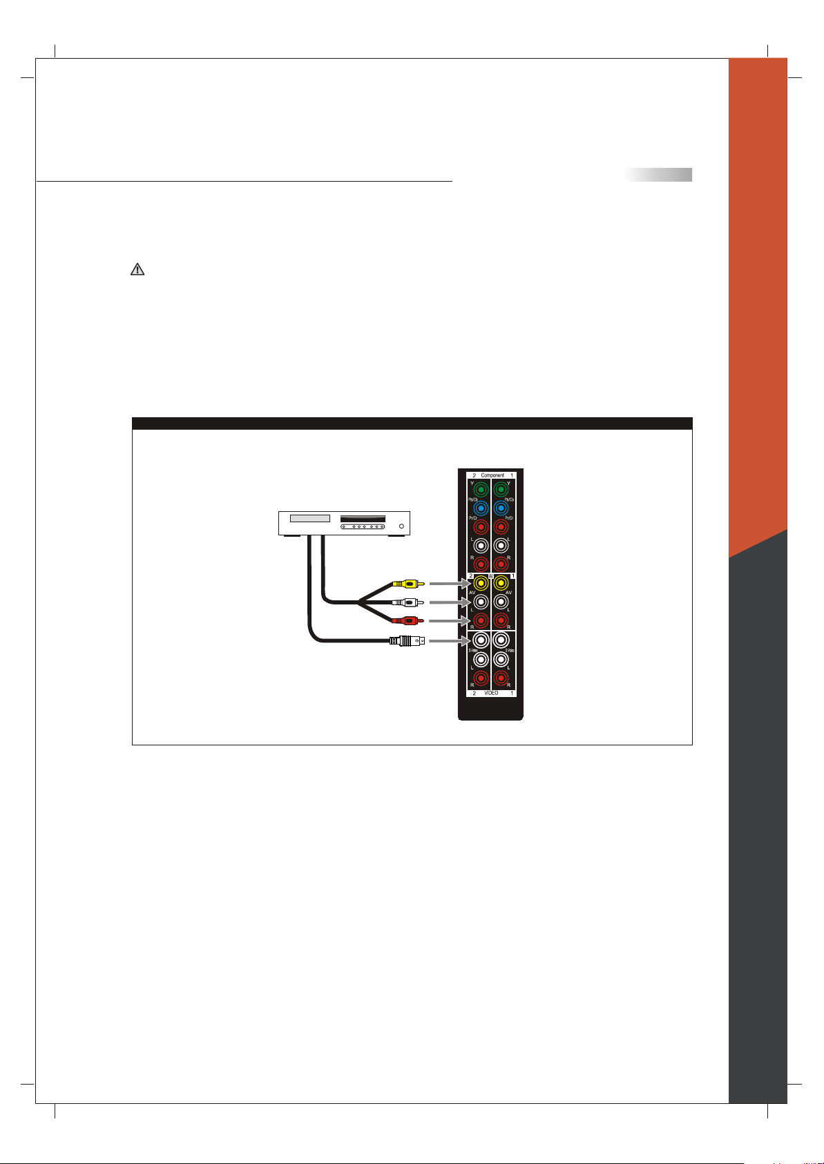
Connecting to a DVD Player with A/V or S Video Cables
Disconnect all power sources before making any connections.
Use this method of connection if your DVD player does not have component (Y, Pb, Pr) jacks.
Note: If your DVD player has component video output connectors, for best picture quality, use the connection
described for Connecting to a DVD Player with Component Connectors.(See page.17)
1.Using an A/V cable, connect the DVD player's Audio OUT jacks to the TV's Audio IN jacks.
2.Using an S-Video Cable, connect the DVD player's S Video OUT jack to the TV's S Video IN jack.
For 265 TFHD Model
Rear of TV
DVD Player
A/V cable with
RCA connector
Yellow
White
Red
English
S Video cable
Note: When you connect video equipment to both the same Video and S-Video input jacks, the display will
automatically select S-Video first.
To view Video signal, please disconnect the S-Video jack or turn off the Video signal on the video equipment.
S-Video is strongly recommended for use if your VCR or video equipment has the option.
S-Video input has better quality of picture than a composite Video signal.
18
HDMI 1
R L
HDMI 2
R
L
VGA /
Component 3
RS232C
Control Port
R
L
Firmware
Upgrade Port
TV Installation and Connection Guide
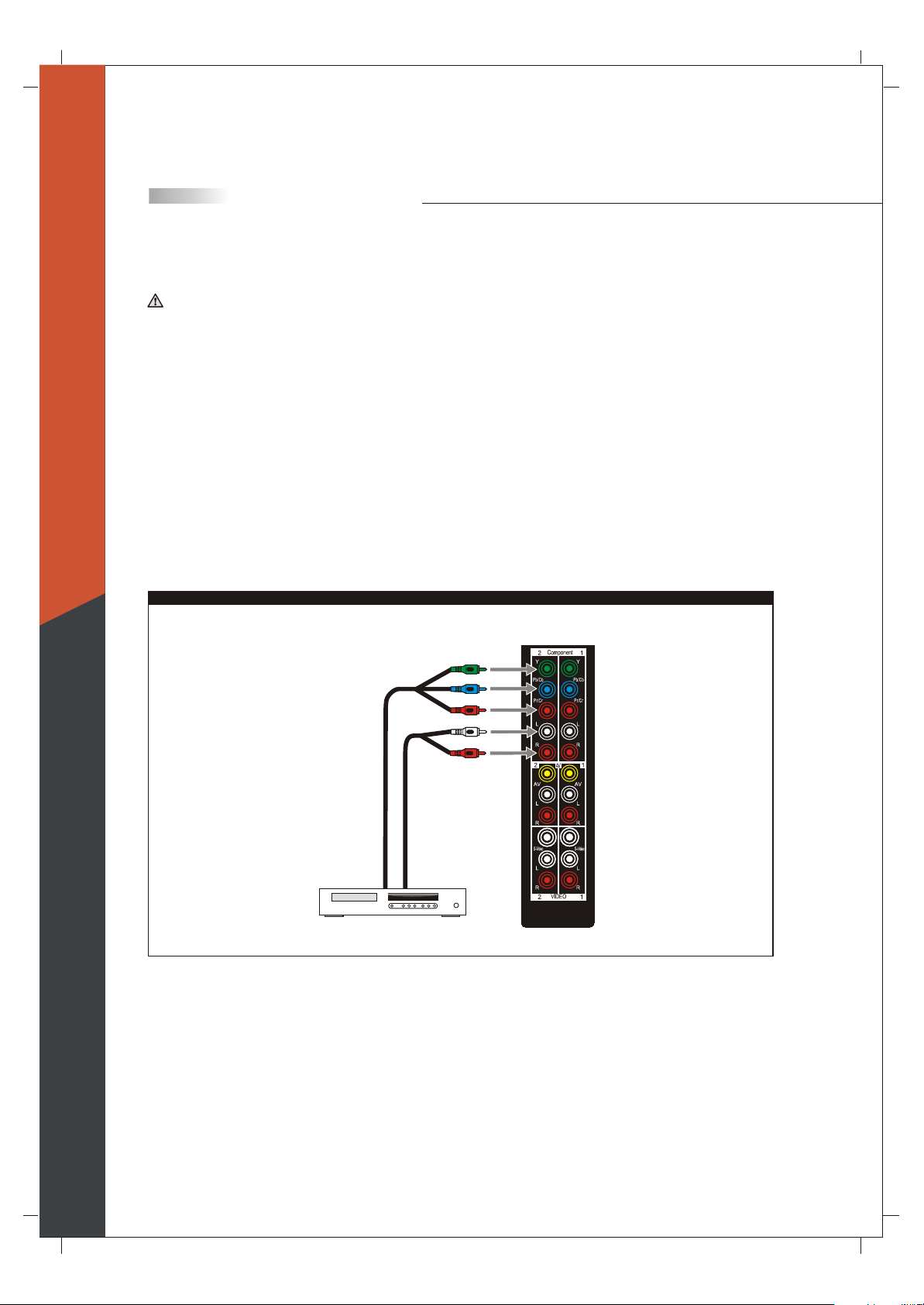
Connecting to a DVD Player with Component Cables
Disconnect all power sources before making any connections.
Use this method of connection if your DVD Player has component (Y, Pb, Pr) jacks.
1.Using a component video cable, connect the DVD Player's Y, Pb and Pr jacks to the Y, Pb and Pr jacks on the
TV.
Colors on Component Video connectors:
Y: Green
Pb (also identified as Cb, CB or B-Y): Blue
Pr (also identified as Cr, CR or R-Y): Red
English
Note: The Y, Pb and Pr jacks on your DVD player are sometimes labeled as Y, Cb and Cr, or B-Y and R-Y.
If so, connect the cables to the matching colors.
2.Using an Audio cable, connect the DVD player's Audio OUT jacks to the TV's Audio in jacks.
For 265 TFHD Model
Rear of TV
Green
Blue
Red
White
Red
Component
cable with
RCA connector
DVD Player
Audio cable
Note: The Y, Pb and Pr jacks do not provide audio, so audio cables must be connected to provide sound.
Note: The YPbPr connection provides the best quality of video signal compared to AV (Composite) and
S-Video connection.
Note: YPbPr is set at default to best perform with FHD 1080P content, set Input to "Interlace DVD" for
best performance with regular 480i and 480p content.
(Menu - Picture - Mode - Input = "Interlace DVD")
19
HDMI 1
R L
HDMI 2
R
L
VGA /
Component 3
RS232C
Control Port
R
L
Firmware
Upgrade Port
TV Installation and Connection Guide
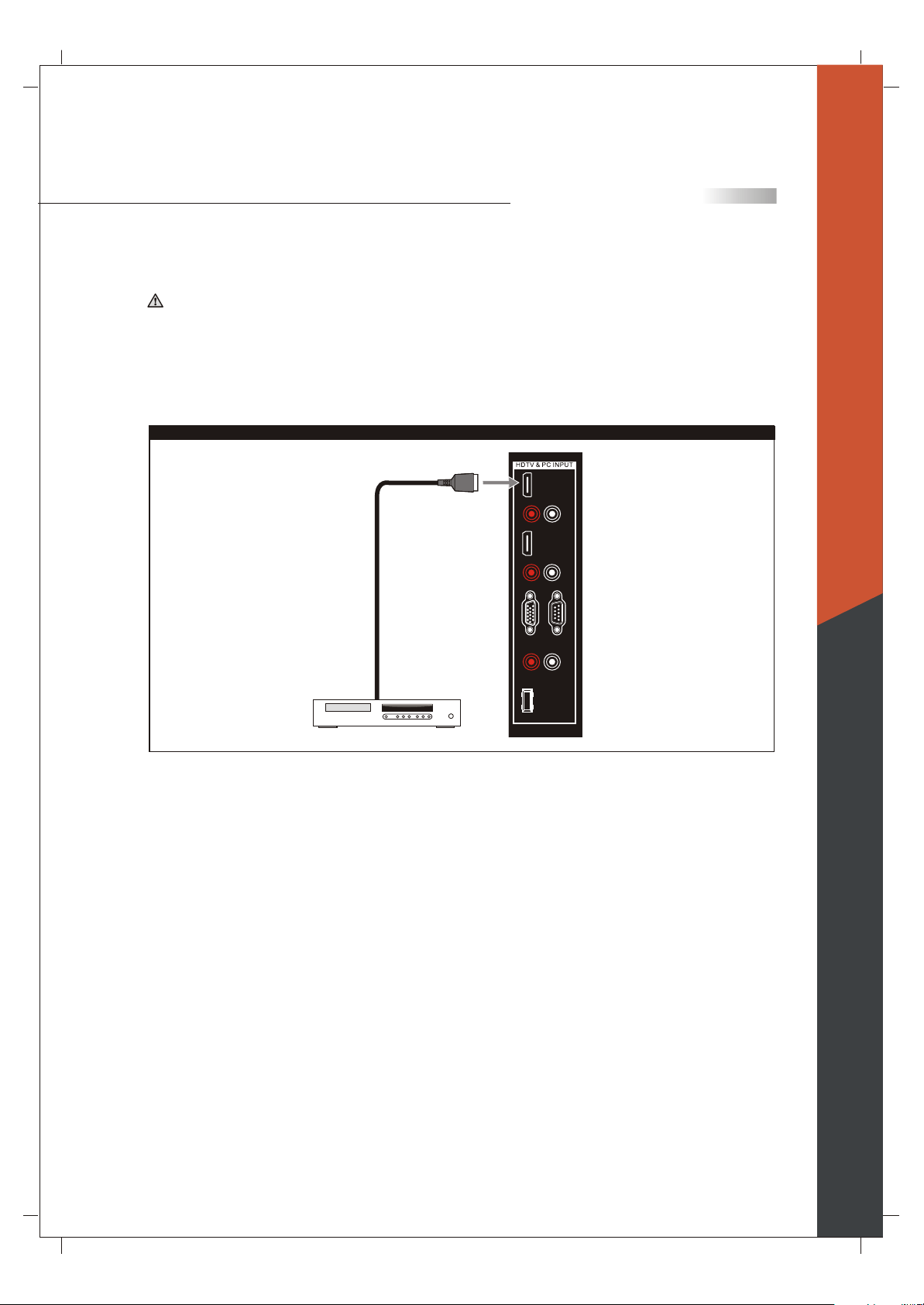
Connecting to a DVD Player with HDMI Cables
Disconnect all power sources before making any connections.
Use this method of connection if your DVD Player has HDMI jacks.
1.Using a HDMI cable, connect the DVD Player's HDMI output terminal to the TV's HDMI-HDCP input
terminal.
For 265 TFHD Model
Rear of TV
HDMI cable
DVD Player
Note: HDCP is a copy protected digital connection that receives analog or digital video and audio signals
from equipment with a HDMI output that features the HDCP function. HDMI allows the transfer of digital
uncompressed data to the TV. This connection is superior when compared to the Component, S Video or AV
(composite) connections.
Note: HDMI signal is purely digital and provides a better picture, it is better than component, S-Video or
Video connections. It is strongly recommended to use this connection if you have this function on your
equipment.
English
20
HDMI 1
R L
HDMI 2
R
L
VGA /
Component 3
RS232C
Control Port
R
L
Firmware
Upgrade Port
English
TV Installation and Connection Guide
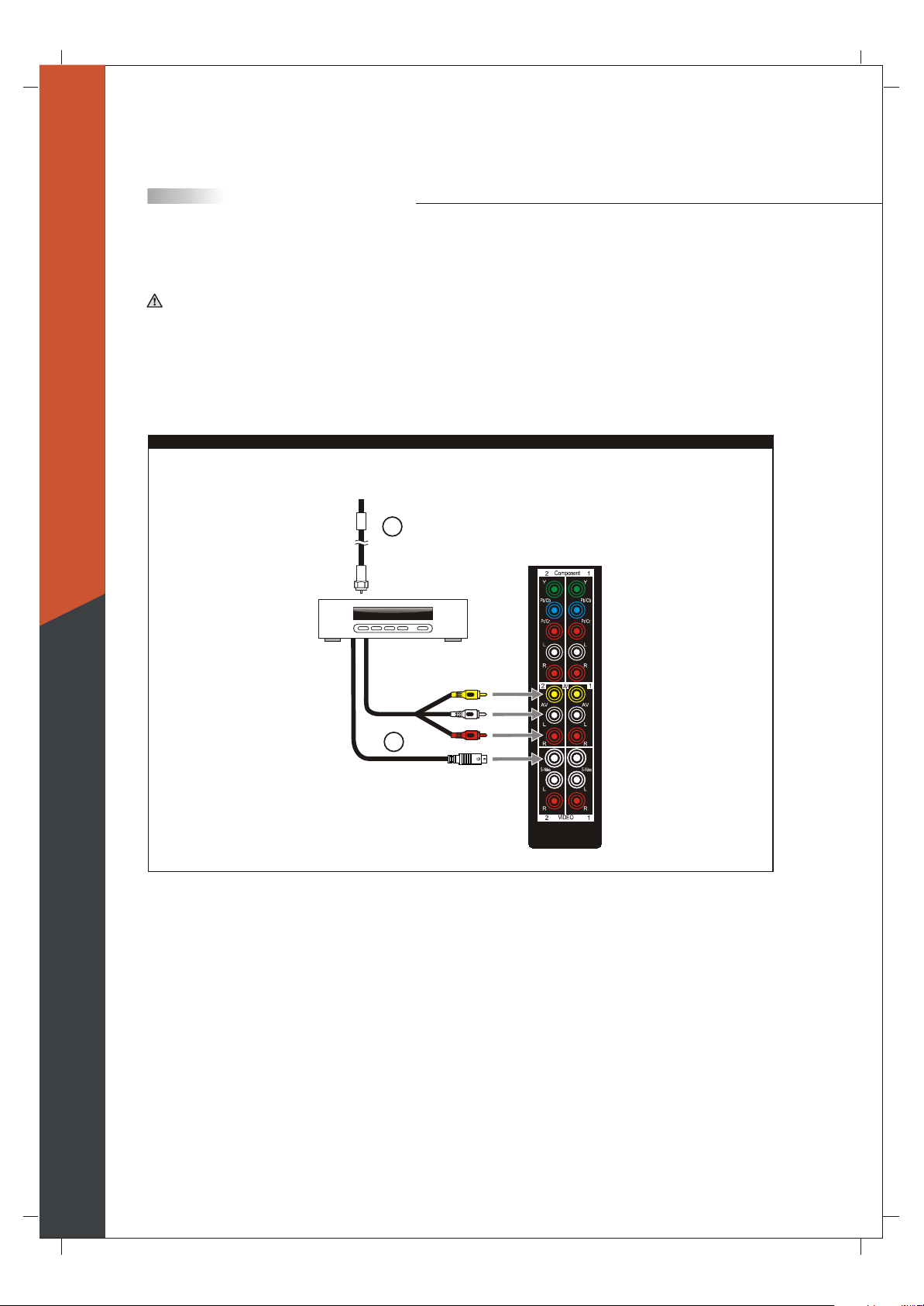
Connecting to a Satellite Receiver or Cable Box with A/V Connectors
Disconnect all power sources before making any connections.
1.Connect a 75-ohm coaxial cable from your Cable TV to the Satellite Receiver's or Cable Box's Ant
(Antenna) jack.
2.Using Audio and S Video cables, connect the satellite receiver's Audio and S-Video OUT jacks to the TV
Audio and S Video IN jacks.
For 265 TFHD Model
Satellite Receiver
or Cable Box
1
(75-ohm
coaxial cable)
Rear of TV
A/V cable with
RCA connector
Yellow
White
Red
2
S Video cable
Note: When you connect video equipment to both the same Video and S-Video input jacks, display will
automatically select S Video first.
To view S-Video signal, please disconnect Video jack or turn off the Video signal on the video equipment.
S-Video is strongly recommended for use if your VCR or video equipment has it because S-Video input has
better quality of picture than a composite Video signal.
21
 Loading...