

Page 1
Oki Data CONFIDENTIAL
C9400/C9200
Color LED Page Printer
MAINTENANCE
MANUAL
ODA/OEL/INT
2002-12-10 Rev.6
41388601TH Rev.6 1 / 142
Page 2
Document Revision History
Oki Data CONFIDENTIAL
Rev.No. Date
No.
Corrected items
Page Description of change
Person in
charge
1 2000-12-05 ISSUE EM3 Murakami
2 2000-12-13 8 Correction of errors in K Yamazaki
the parts list
3 2001-05-15 CN11 Kasuya
4 2001-10-12 K Yamazaki
5 2002-11-27 K Yamazaki
6 2002-12-10 NP34 Ueda
41388601TH Rev.6 2 /
Page 3

Oki Data CONFIDENTIAL
PREFACE
This maintenance manual provides procedures and techniques for the troubleshooting, maintenance, and
repair of C9400/C9200.
This manual is written for maintenance personnel, but it should always be accompanied with the C9400/
C9200 User’s Manual for procedures for handling and operating C9400/C9200. For repairing each
component of C9400/C9200, see the Troubleshooting manual.
[Notices]
The contents of this manual are subject to change without prior notice.
Although reasonable efforts have been taken in the preparation of this manual to assure its accuracy, this
manual may still contain some errors and omissions. OKI will not be liable for any damage caused or
alleged to be caused, by the customer or any other person using this maintenance manual to repair,
modify, or alter C9400/C9200 in any manner.
[Warning]
Many parts of C9400/C9200 are very sensitive and can be easily damaged by improper servicing. We
strongly suggest that C9400/C9200 be serviced by OKI’s authorized technical service engineers.
41388601TH Rev.6 3 /
Page 4

Oki Data CONFIDENTIAL
CONTENTS
1. SPECIFICATIONS ............................................................................................ 6
1.1 Basic System Configuration............................................................................................. 6
1.2 Printer Engine Specifications ........................................................................................... 7
1.3 Option Configuration ........................................................................................................ 8
1.4 Specifications................................................................................................................... 9
2. PARTS REPLACEMENT................................................................................11
2.1 Precautions in Replacing Parts...................................................................................... 11
2.2 Parts Layout................................................................................................................... 13
2.3 Replacing Parts..............................................................................................................20
2.3.1 Top cover.......................................................................................................... 21
2.3.2 LED Assy/ LED Assy spring ............................................................................. 22
2.3.3 Top cover unit................................................................................................... 23
2.3.4 Control panel Assy/ Control panel bezel/ LED control PWB/ Toner sensor/
Stack full sensor/ Control panel tape harness/ Eject roller ............................... 24
2.3.5 Top cover handle/ Tope cover latch/ Top cover latch spring............................ 25
2.3.6 Eject guide Assy ............................................................................................... 26
2.3.7 Cassette Assy/ Blind cover/ Side cover R Assy ............................................... 27
2.3.8 Feed rollers....................................................................................................... 28
2.3.9 Left side cover .................................................................................................. 29
2.3.10 Face-up tray ..................................................................................................... 30
2.3.11 Front cover ....................................................................................................... 31
2.3.12 Rear cover........................................................................................................ 32
2.3.13 Multipurpose tray Assy/ Multipurpose tray cover Assy/ Links/
Multipurpose tray top cover/ Multipurpose tray drive gear................................ 33
2.3.14 Drum contact Assys.......................................................................................... 34
2.3.15 Registration roller Assy (A)/ Registration drive gear (A)................................... 35
2.3.16 Registration roller Assy (B)............................................................................... 36
2.3.17 Registration clutch, Registration motor Assy.................................................... 37
2.3.18 Cooling fan ....................................................................................................... 38
2.3.19 Color registration sensor Assy.......................................................................... 39
2.3.20 Duplex guide Assy............................................................................................ 40
2.3.21 Electrical chassis/ Electrical chassis cooling fan.............................................. 41
2.3.22 Printer engine controller PWB.......................................................................... 42
2.3.23 Printer unit chassis........................................................................................... 43
2.3.24 Entrance cassette sensor actuator................................................................... 44
2.3.25 Entrance sensor PWB...................................................................................... 45
2.3.26 Entrance MT sensor actuator and Entrance belt sensor actuator.................... 46
2.3.27 Main motor fan/ Fuser eject roller..................................................................... 47
2.3.28 Eject sensor Assy............................................................................................. 48
2.3.29 Fuser latching handle (L).................................................................................. 49
2.3.30 Belt motor Assy ................................................................................................ 50
2.3.31 Fuser latching handle (R)................................................................................. 51
2.3.32 Main motor Assy............................................................................................... 52
2.3.33 Contact Assy/ Side plate Assy.......................................................................... 53
2.3.34 Low voltage power supply................................................................................ 54
2.3.35 High voltage power supply ............................................................................... 55
2.3.36 Main feed Assy................................................................................................. 56
2.3.37 Fuser unit.......................................................................................................... 57
2.3.38 Belt unit............................................................................................................. 58
2.3.39 Duplex unit........................................................................................................ 59
2.3.40 CU Assy............................................................................................................ 60
41388601TH Rev.6 4 /
Page 5

Oki Data CONFIDENTIAL
3. Adjustment .................................................................................................... 62
3.1 Maintenance Menu and Its Functions ............................................................................ 62
3.2 Short Plug Settings ........................................................................................................ 63
3.3 Printing Singly Using Controller-Equipped Printer ......................................................... 63
3.4 Adjustment after Part Replacement ............................................................................... 64
3.5 Color Balance Adjustment ............................................................................................. 65
3.6 EEPROM Replacement after SWA Board and K73 Board Replacement ...................... 67
4. Regular Maintenance .................................................................................... 68
4.1 Parts to be Replaced Regularly ..................................................................................... 68
4.2 Cleaning......................................................................................................................... 68
4.3 Cleaning of LED Lens Array .......................................................................................... 68
4.4 Cleaning of Pick-up Roller ............................................................................................. 68
5. TROUBLESHOOTING PROCEDURES .........................................................69
5.1 Tips for Troubleshooting ................................................................................................ 69
5.2 Check Points before Correcting Image Problems.......................................................... 69
5.3 Tips for Correcting Image Problems .............................................................................. 69
5.4 Preparation for Troubleshooting .................................................................................... 70
5.5 Troubleshooting Flow..................................................................................................... 70
5.5.1 LCD Message List ............................................................................................ 71
5.5.2 LCD message troubleshooting ......................................................................... 79
5.5.3 Image troubleshooting...................................................................................... 90
6. WIRING DIAGRAM...................................................................................... 102
6.1 Resistance Check ........................................................................................................ 102
6.2 Parts Layout on Boards ............................................................................................... 107
7. Parts List...................................................................................................... 111
7.1 Printer Unit Parts List ................................................................................................... 111
7.2 C9400/C9200 Finisher for OEL/INT Parts Layout........................................................ 131
41388601TH Rev.6 5 /
Page 6
Job
offset
M
M
M
M
M
M
M
LED Head
Junction Board
Pulse Motors
Engine Controller
Low-Voltage
Power Unit
Fuser Unit
High-Voltage
Power Unit
2nd/3rd T r ay/
Large-Capacity
Tray
Duplex Unit
Belt Unit
<Sensors, Switches and Thermistors>
Paper carrier sensors
Paper size detection
Fuser temperature detection
Ambient temperature and humidity detection
Toner remaining detection
Color registration sensor
ID, belt and fuser checks
C-ID
Unit
M-ID
Unit
Y-ID
Unit
K-ID
Unit
C ID
M
Heater
M ID
Y ID
K ID
Belt
MT/
Registration
Hopping
Geared
motor
DC motor
Operator Panel
Centronics
USB
IDE
HDD
DC
FAN
Ethernet
ROM DIMM × 3
SDRAM DIMM
× 4
Controller
Block
1. SPECIFICATIONS
1.1 Basic System Configuration
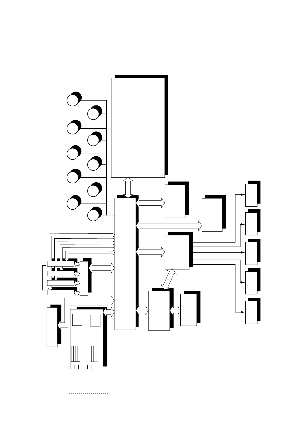
The basic system configuration of C9400/C9200 is illustrated in Figure 1.1.
Oki Data CONFIDENTIAL
Figure 1.1
41388601TH Rev.6 6 /
Page 7
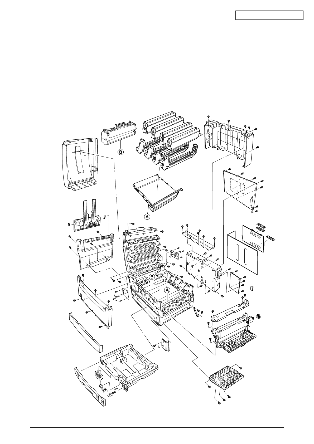
1.2 Printer Engine Specifications
The inside of the printer is composed of the followings:
• Electrophotographic Processor
• Paper Paths
• Controller Block (CU and PU)
• Operator Panel
• Power Units (High-Voltage Unit and Low-Voltage Unit)
Figure 1-2 shows the printer configuration.
Oki Data CONFIDENTIAL
Figure 1.2
41388601TH Rev.6 7 /
Page 8
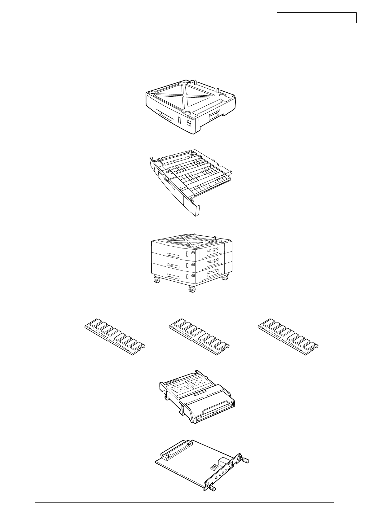
1.3 Option Configuration
The followings are available as options on C9400/C9200.
(1) 2nd Tray/ 3rd Tray
(2) Duplex Unit
Oki Data CONFIDENTIAL
(3) Large-Capacity Tray
(4) Expansion Memory 64/128/256MB
(5) Internal Hard Disk
(6) Ethernet Board
41388601TH Rev.6 8 /
Page 9
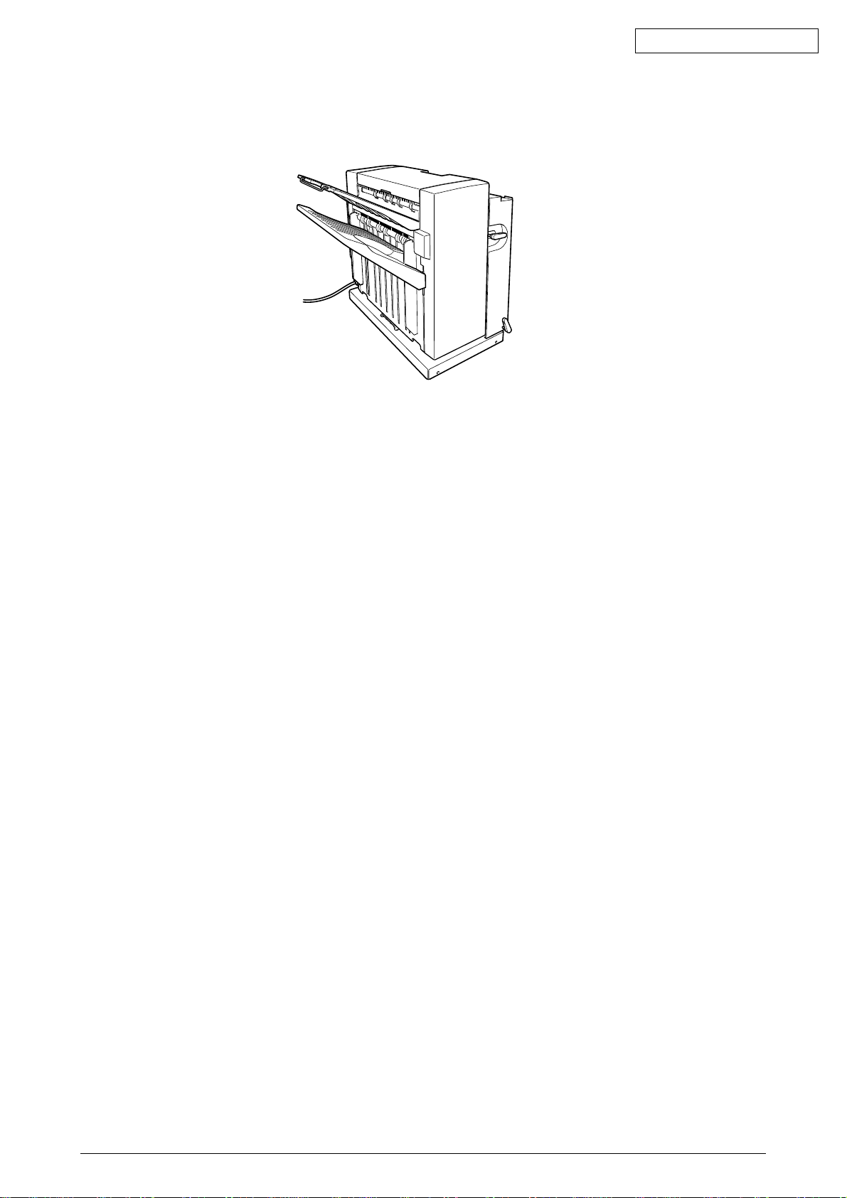
(7) Finisher Unit (for C9400/C9200 OEL/INT Version)
1.4 Specifications
Oki Data CONFIDENTIAL
(1) Dimensions Height: 460mm Width: 666mm Length: 626mm
(2) Weight 72kg
(3) Paper Type: Ordinary paper and transparencies (Recommended: ML OHP01)
Size: Postal card, Legal 13" or 14", Executive, A4, A5, B5, A6, A3 A3-Nobi, B4
(Only the 1st tray and the front feeder support A6 and postal card
sizes.)
Weight: 1st tray 55 kg to 90 kg (64 to 105g/m2)
Front feeder 55 kg to 140 kg (64 to 163g/ m2)
(4) Print Speed Color: 21 pages per minute (Transparency: 5 pages per minute)
Monochrome: 26 pages per minute (Transparency: 15 pages per minute)
Postal Card, Label, Thick Paper: 10 pages per minute
(5) Resolution 600 × 600 dots per inch
(6) Power Input 100VAC ±10%
(7) Power Consumption Peak: 1400W Normal Operation: 550W (5% duty)
Idle: 150W Power Saving Mode: 50W
(8) Frequency 50Hz or 60Hz ± 2%
(9) Noise Operating: 54 dB (without Second tray)
Standby: 45 dB
Power Saving: 43 dB
(10) Consumable Life Toner Cartridge: 7,500 pages (5% duty)
Large-Capacity Toner Cartridge: 15,000 pages (5% duty)
(in each of Y, M, C and K)
Image Drum: 39,000 pages (5% duty, Continuous printing)
(in each of Y, M, C and K)
(11) Parts Replaced Periodically Fuser Unit Assy: Every 80,000 pages
Belt Cassette Assy: Equivalent of 80,000 pages (3P/J)
Transfer Belt cartridge: 60,000 prints
41388601TH Rev.6 9 /
Page 10
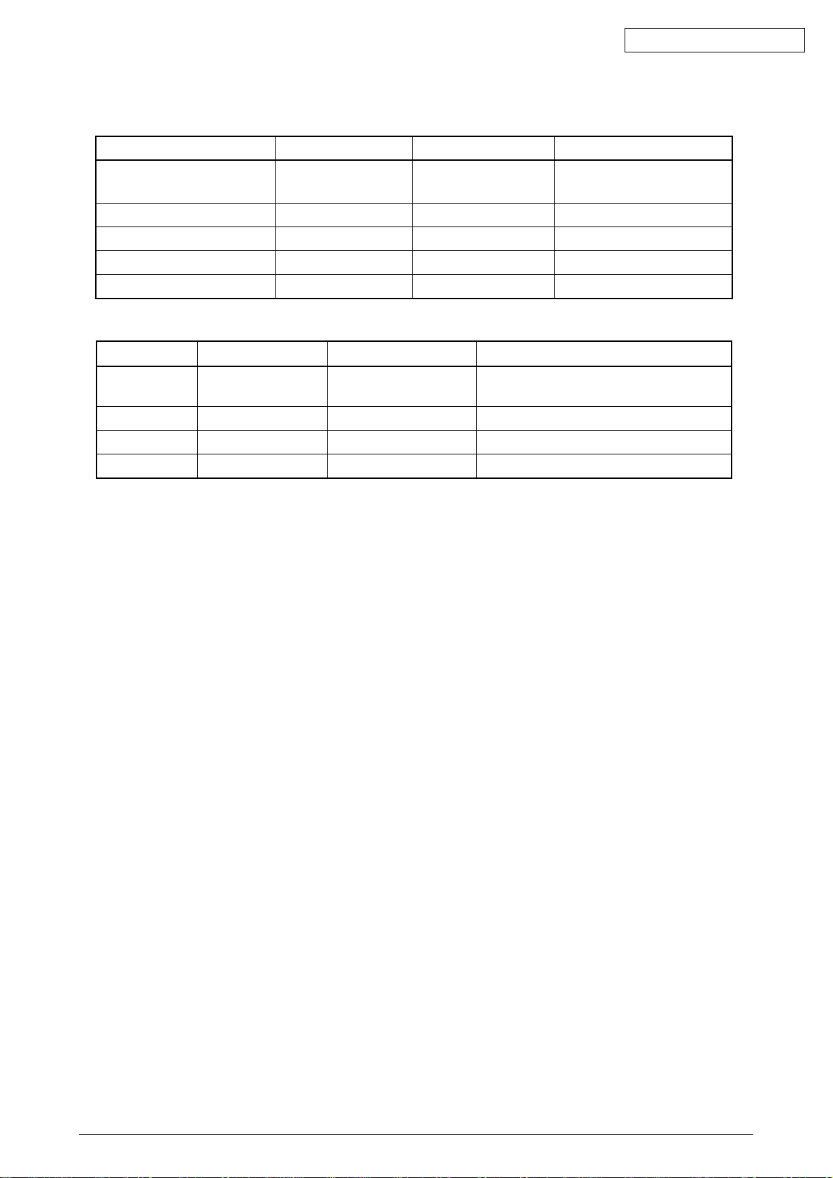
(12) Temperatures and Relative Humidities
Temperature
Temperature (ºF) RemarkTemperature (ºC)
Oki Data CONFIDENTIAL
Operating 50 to 89.6 10 to 32
Non-Operating 32 to 109.4 0 to 43 Power-off
Storage (Max. One Year) -14 to 109.4 -10 to 43 With drum and toner
Transport (Max. One Month) -20 to 122 -29 to 50 With drum and without toner
Transport (Max. One Month) -20 to 122 -29 to 50 With drum and toner
17 to 27ºC (Temperatures to
assure full color print quality)
Humidity
Relative Humidity (%) Max. Wet-Bulb Temperature (ºC) Remark
Operating 20 to 80 25 50 to 70%
(Humidities to assure full color print quality)
Non-Operating 10 to 90 26.8 Power-off
Storage 10 to 90 35
Transport 10 to 90 40
(13 Printer Life 1,000,000 pages (on a A4 basis) or five years
41388601TH Rev.6 10 /
Page 11
2. PARTS REPLACEMENT
This section describes the procedure for replacing the parts, assemblies and units in the field. The
replacing procedure is given for detachment. To attach, use the reverse procedure.
2.1 Precautions in Replacing Parts
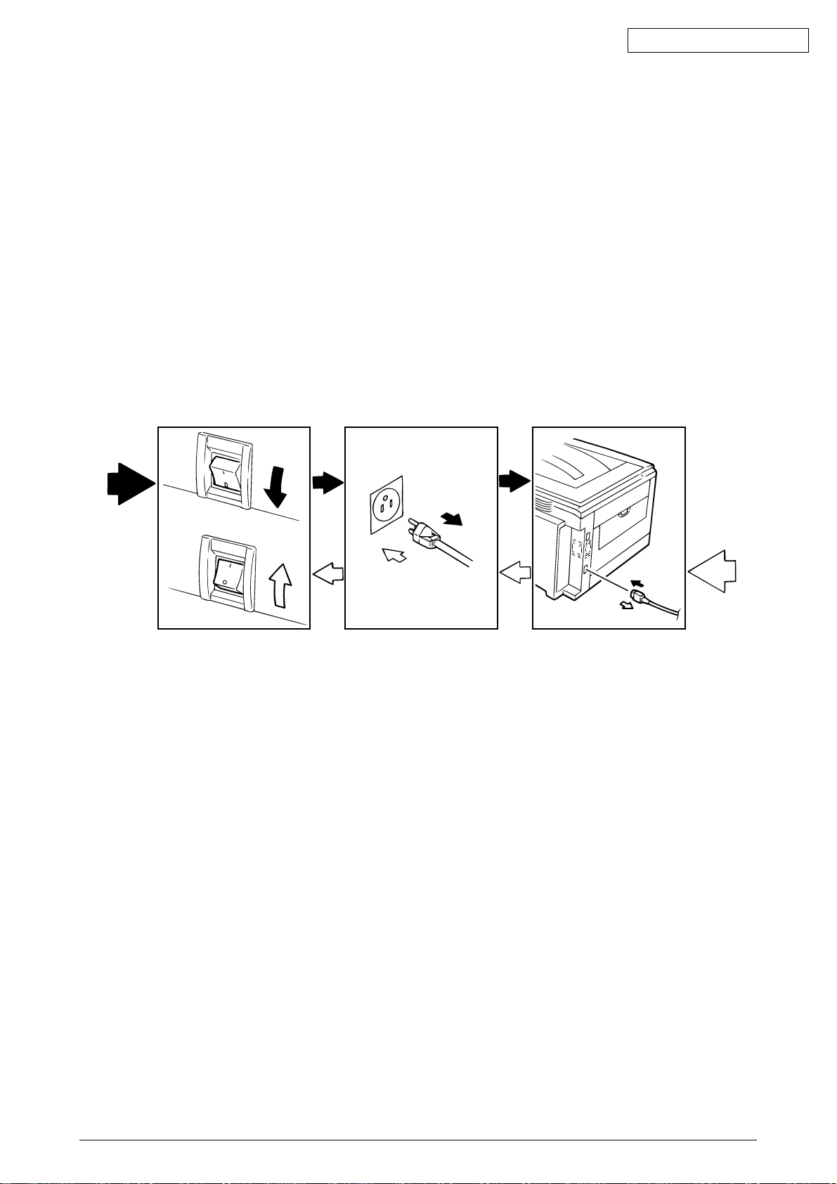
(1) Before replacing the parts, be sure to remove the CA cable and the interface cable.
(a) To remove the AC cable, always use the following procedure.
1 Flip the power switch of the printer off (to “O”).
2 Pull the AC inlet plug of the AC cable out of the AC receptable.
3 Remove the AC cable and the interface cable from the printer.
(b) To connect the printer again, always use the following procedure.
1 Connect the AC cable and the interface cable to the printer.
2 Insert the AC inlet plug into the AC receptacle.
3 Flip the power switch of the printer on (to “I”).
Oki Data CONFIDENTIAL
Disconnect
(2) Do not disassemble the printer so long as it operates properly.
(3) Minimize the disassembly. Do not detach parts other than those shown in the replacing
(4) For maintenance applications, use designated tools.
(5) Follow the order instructed to disassemble the printer. Incorrect order may damage the
(6) Small parts such as screws and collars tend to get lost, so temporarily place and fix them in
(7) When handling ICs and circuit boards such as microprocessors, ROMs and RAMs, do not
(8) Do not place the printed circuit boards directly on the printer or the floor.
Connect
procedure.
parts.
their original positions.
use gloves that likely to have static.
41388601TH Rev.6 11 /
Page 12
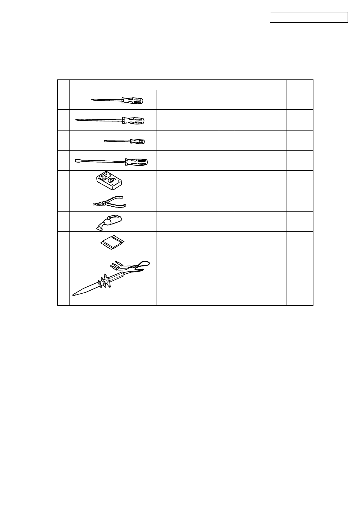
[Maintenance Tools]
Table 2-1 lists tools necessary to replace the units.
Table 2-1 Maintenance Tools
Oki Data CONFIDENTIAL
No.
1
2
3
4
5
6
7 1
8
9
No. 1-100 Philips
screwdriver
No. 2-200 Philips
screwdriver, Magnetized
No. 3-100 screwdriver
No. 5-200 screwdriver
Digital multimeter
Pliers
Handy cleaner
LED Head cleaner
P/N 4PB4083-2248P001
High voltage probe
Q' ty Place of use RemarksService Tools
1
2~2.5 mm screws
1
3~5 mm screws
1
1
1
1
1
Cleans LED head
1
41388601TH Rev.6 12 /
Page 13
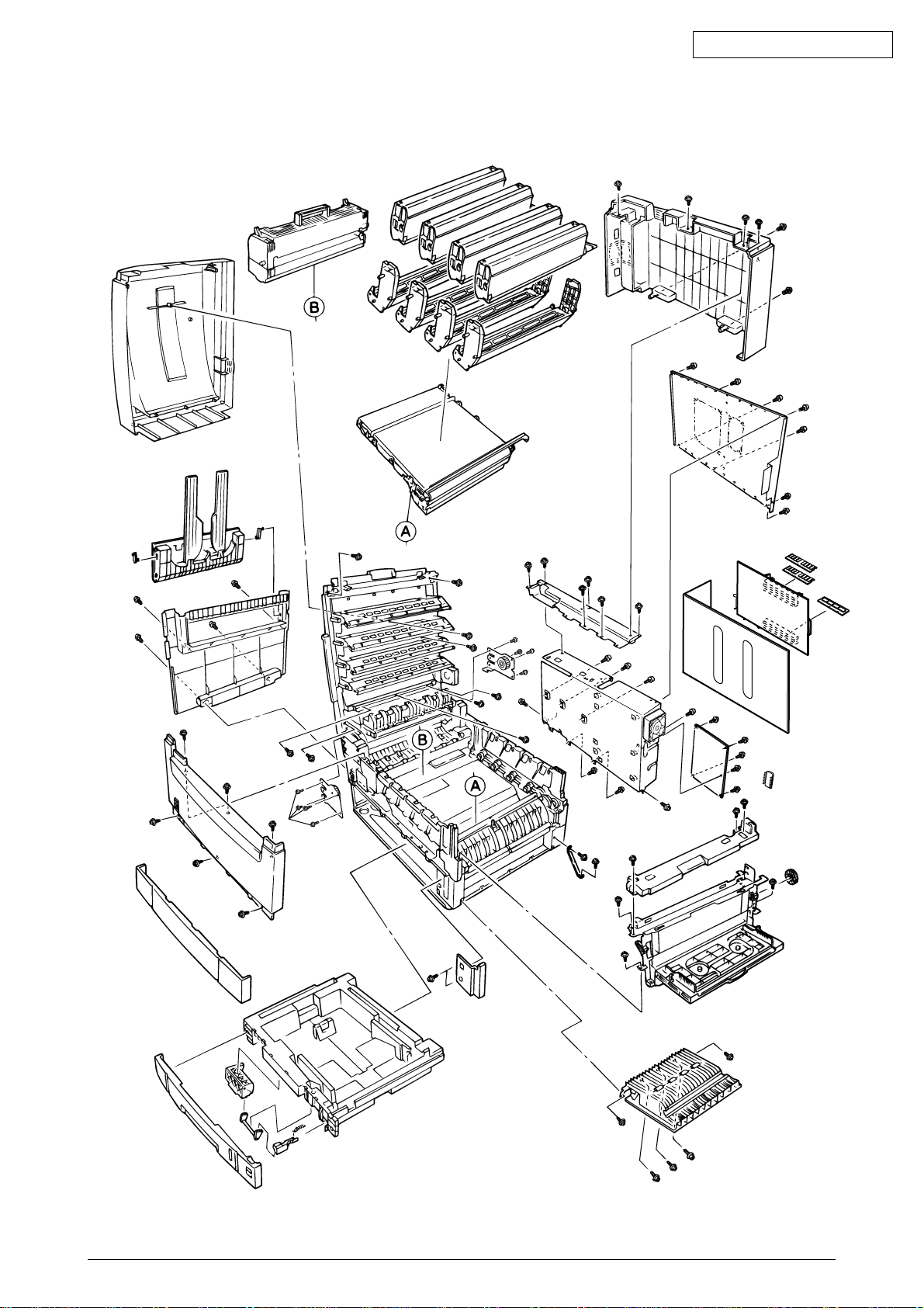
2.2 Parts Layout
Oki Data CONFIDENTIAL
Figure 2.1
41388601TH Rev.6 13 /
Page 14
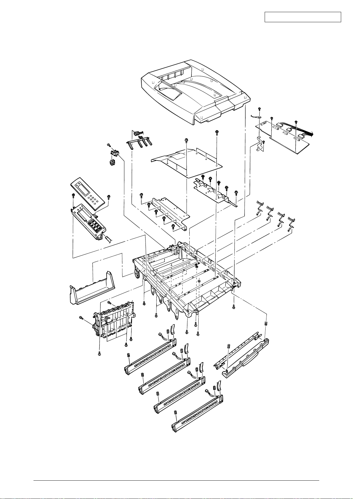
[Top Cover Assy]
Oki Data CONFIDENTIAL
Figure 2.2
41388601TH Rev.6 14 /
Page 15
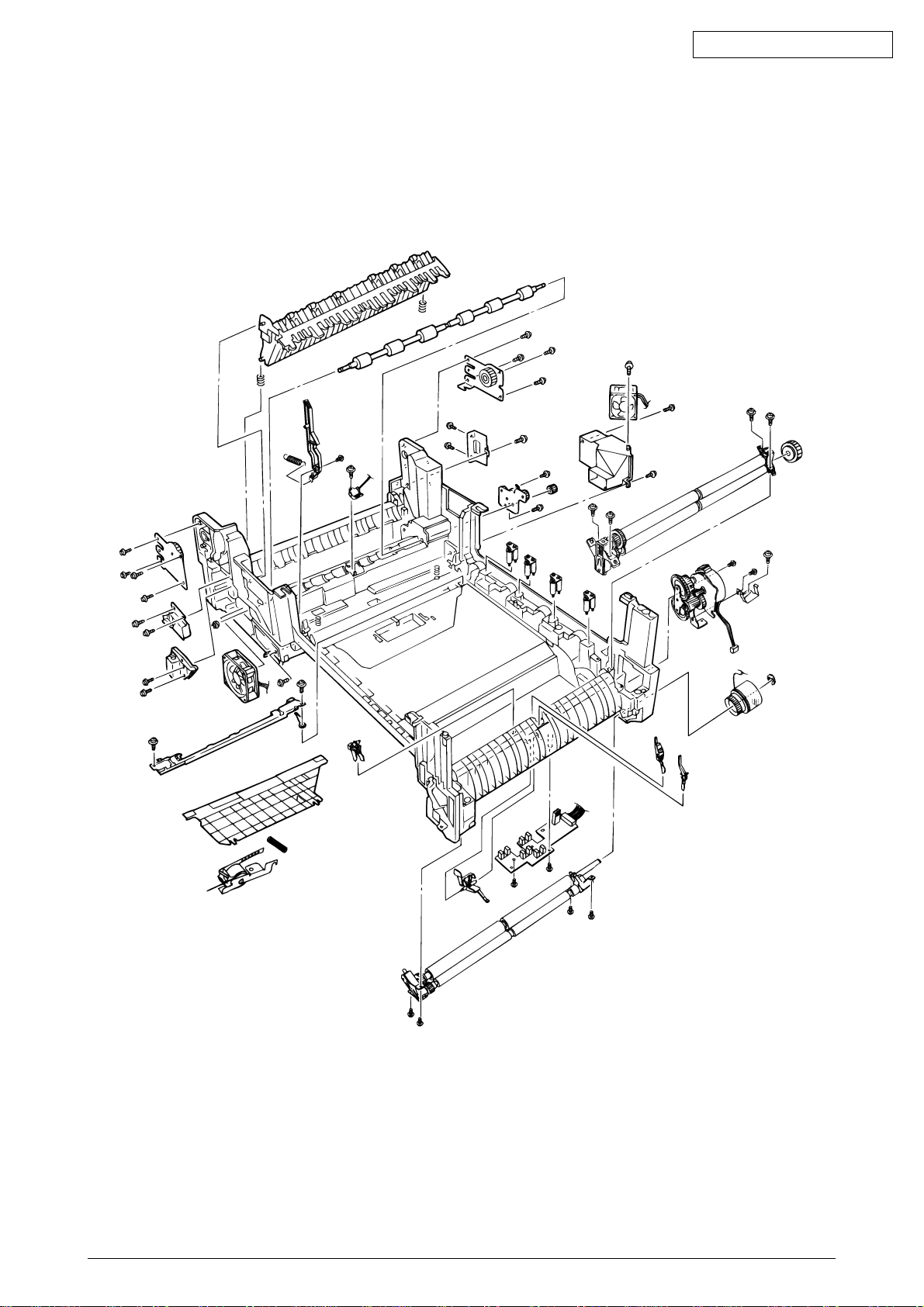
[Printer Unit-1/2]
Oki Data CONFIDENTIAL
Figure 2.3
41388601TH Rev.6 15 /
Page 16
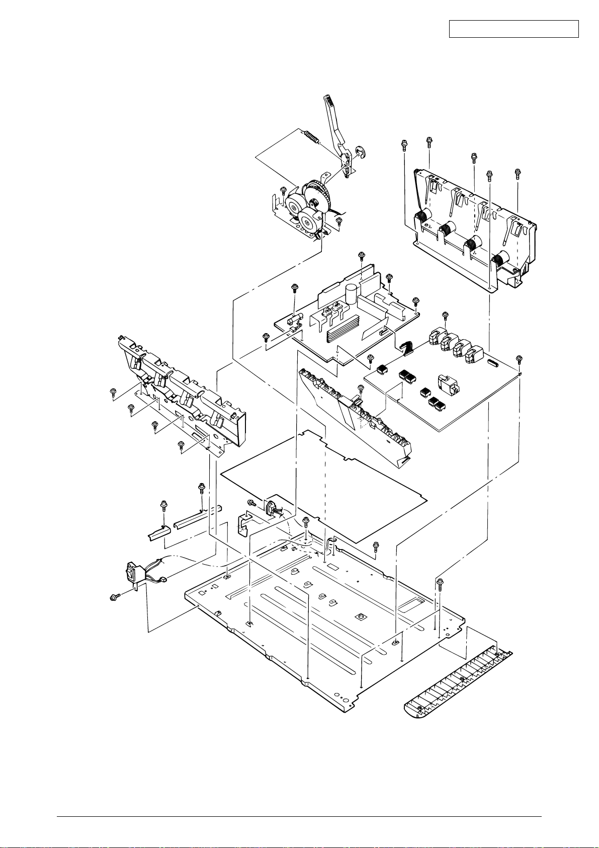
[Printer Unit-2/2]
Oki Data CONFIDENTIAL
Figure 2.4
41388601TH Rev.6 16 /
Page 17
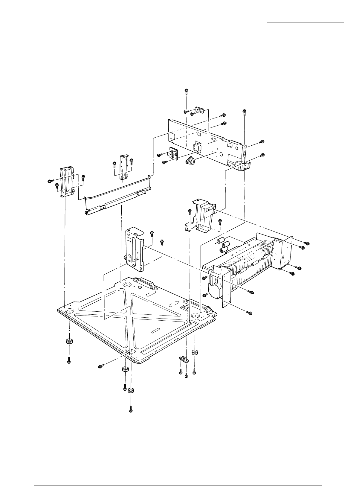
[Cassette Guide Assy (L), (R)]
Oki Data CONFIDENTIAL
Figure 2.5
41388601TH Rev.6 17 /
Page 18
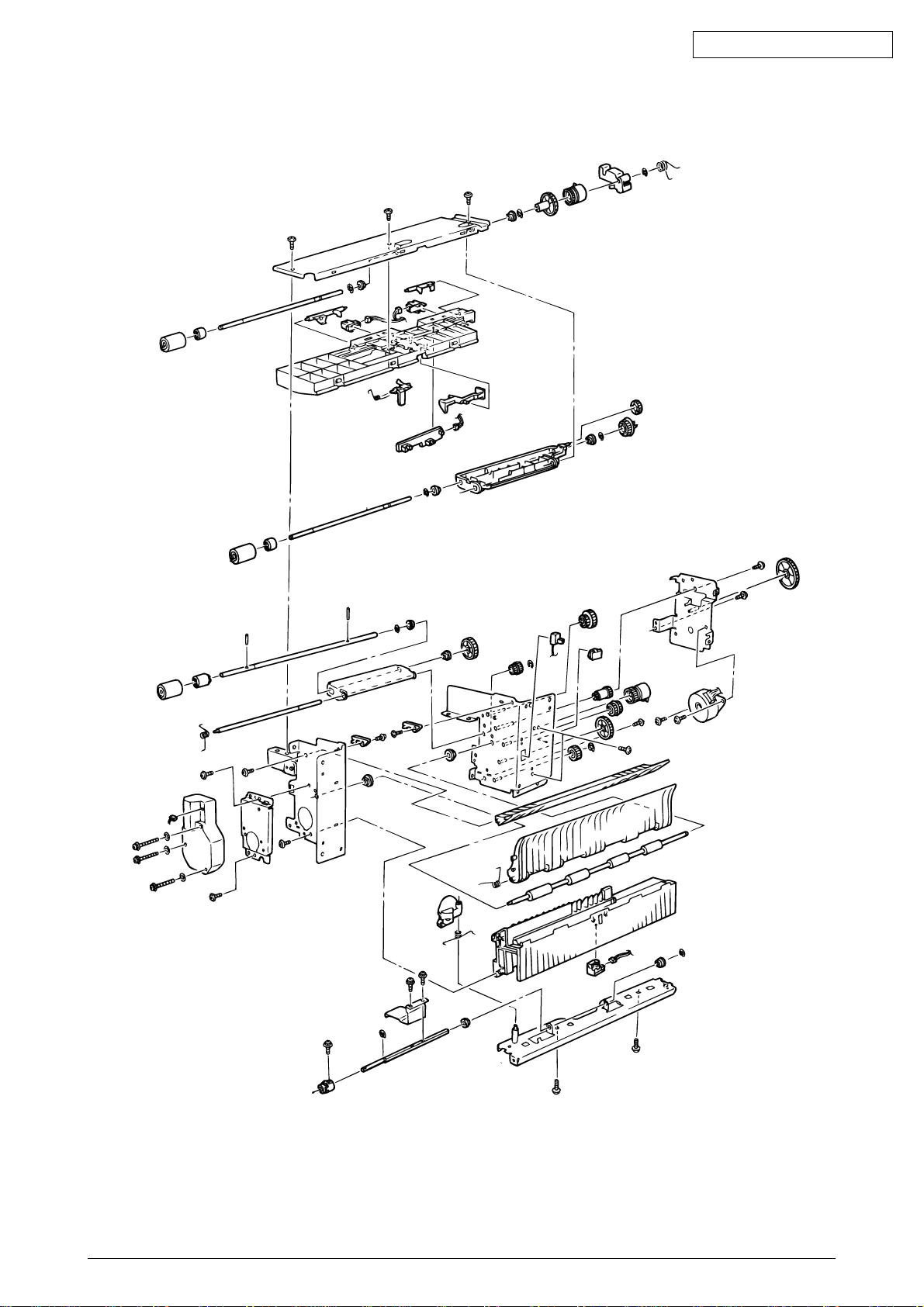
Oki Data CONFIDENTIAL
Figure 2.6
41388601TH Rev.6 18 /
Page 19
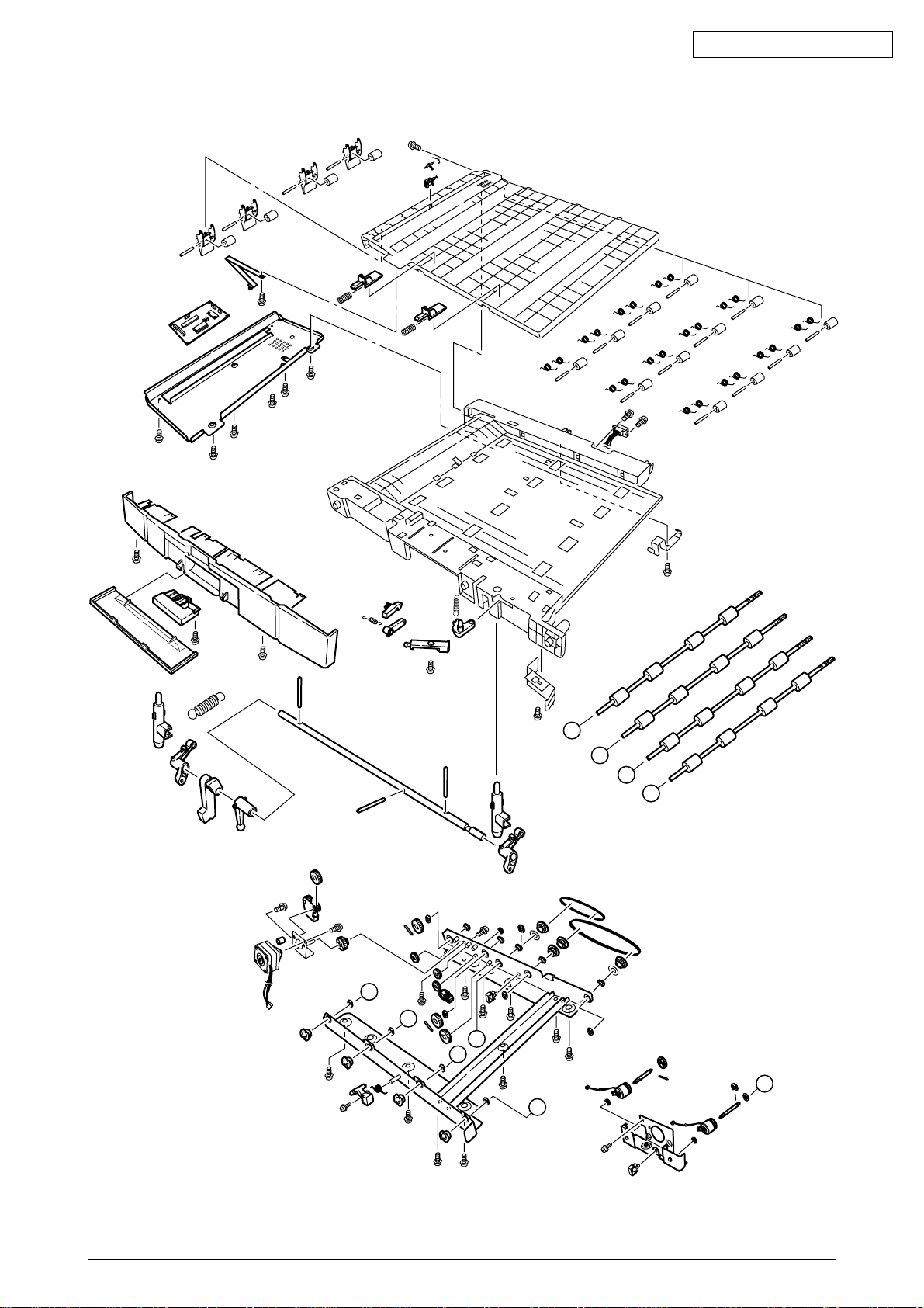
[Duplex Unit]
Oki Data CONFIDENTIAL
D
C
B
A
D
C
E
B
E
A
Figure 2.7
41388601TH Rev.6 19 /
Page 20
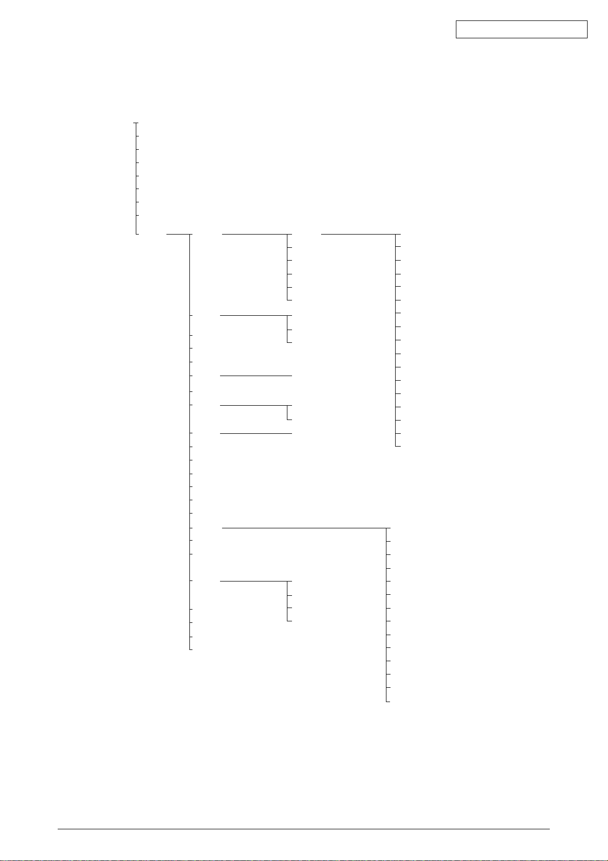
2.3 Replacing Parts
This section describes how to replace the parts and assemblies illustrated below.
41531301 41515110
Print Engine Controller PWB (2.3.22)
41502304 × 4
LED Assy (2.3.2)
40737401
Power-Unit AC-DC Switching (115V) (2.3.34)
40737501
Power-Unit AC-DC Switching (230V) (2.3.34)
40737601
HV Power Supply (2.3.35)
41531402, 41531404
Fuser Unit (2.3.37)
41531502
Belt Unit (2.3.38)
41178202
Duplex Unit (2.3.39)
41480901
Printer NIP
41483001
Printer Unit
41481001
Unit-Lower-Frame (2.3.36)
41500101
Insurator
41483701
Main Cooling Fan Assy (2.3.18)
2381018P0001
HV Tape Harness
41484101
Electrical Chassis (2.3.21)
41483801
Main Motor Assy (2.3.32)
41483902
Belt Motor Assy (2.3.30)
41489001
Plate Assy-Side (2.3.33)
41493002
Multipurpose Tray (2.3.13)
41276502
Rear Cover (2.3.12)
41277402
Left Side Cover (2.3.9)
41481202
Right Side Cover (2.3.7)
41276402
Front Cover (2.3.11)
41277502
Face Up Tray (2.3.10)
41504401
Top Cover
41484402
Top cover (2.3.1)
40866212
Control panel Bezel (2.3.4)
41493002
Multipurpose Tray Assy (2.3.13)
41484902
Cassette Assy (2.3.7)
41277902
Cover-Blind (2.3.7)
41481701
Feed-Roller (2.3.8)
40863801
Plate-Side (2.3.21)
41483102
Printer Chassis (2.3.23)
41483202
Regist Roller Assy (A) (2.3.15)
41483301
Regist Roller Assy (B) (2.3.16)
41483401
Registration Motor Assy (2.3.17)
41187101
Registration Clutch (2.3.17)
41486601
Duplex Guide Assy (2.3.20)
41481301
Main Feed Assy (2.3.36)
41515801
PCE-Size Sence (2.3.36)
22011000P0140
IMSA-9714N-14A (2.3.36)
41490702
Electrical Chassis Cooling Fan
40841402
Fuser Latching Handle (R) (2.3.31)
41628301
Fuser Latching Handle Spring (2.3.31)
40850201
Contact Assy (2.3.33)
41045802 × 2
Link (2.3.13)
41486202
MT Tray Cover Assy (2.3.13)
41278002
MT Top Cover (2.3.13)
40325101
MT Drive Gear (2.3.13)
Oki Data CONFIDENTIAL
40841302
Fuser Latching Handle (L) (2.3.29)
41628301
Fuser Latching Handle Spring (2.3.29)
40841601
Entrance Sensor Actuator #1 (2.3.24)
41578501
Entrance Sensor Actuator #2 (2.3.26)
40841801
Entrance Sensor Actuator #3 (2.3.26)
41621801
Registration Shutter Solenoid Assy
41488801
Registration Shutter
41589401
Registration Shutter Spring
41641701
Fuser Driver Gear-A (2.3.27)
41095901
Fuser Exit Roller (2.3.27)
4PP4043-4489P001
Fuser Exit Roller Bushing (L) (2.3.27)
4PP4076-3949P001
Fuser Exit Roller Bushing (R) (2.3.27)
41189701 × 4
Drum Contact Assy (2.3.14)
41258301
Entrance Sensor PWB (2.3.25)
41491001
Color Registration Sensor Assy (2.3.19)
41073601
Exit Sensor Assy (2.3.28)
41483701
Main Motor FAN Assy (2.3.27)
40861001 × 8
LED Assy Spring (2.3.2)
41257902
LED Control PWB (Y71) (2.3.4)
41349801
Stack Full Sensor (2.3.4)
41349301 × 4
Eject Roller (2.3.4)
41484501
Control Panel Assy (2.3.4)
2381005P0015
Control Panel Tape Harness (2.3.4)
41514101
LED Harness K
41514102
LED Harness Y
41514103
LED Harness M
41514104
LED Harness C
41328402
Top Cover Handle (2.3.5)
41277602
Top Cover Latch (2.3.5)
40861401 × 2
Top Cover Latch Spring (2.3.5)
41484701
Eject Guide Assy (2.3.6)
41388601TH Rev.6 20 /
Page 21
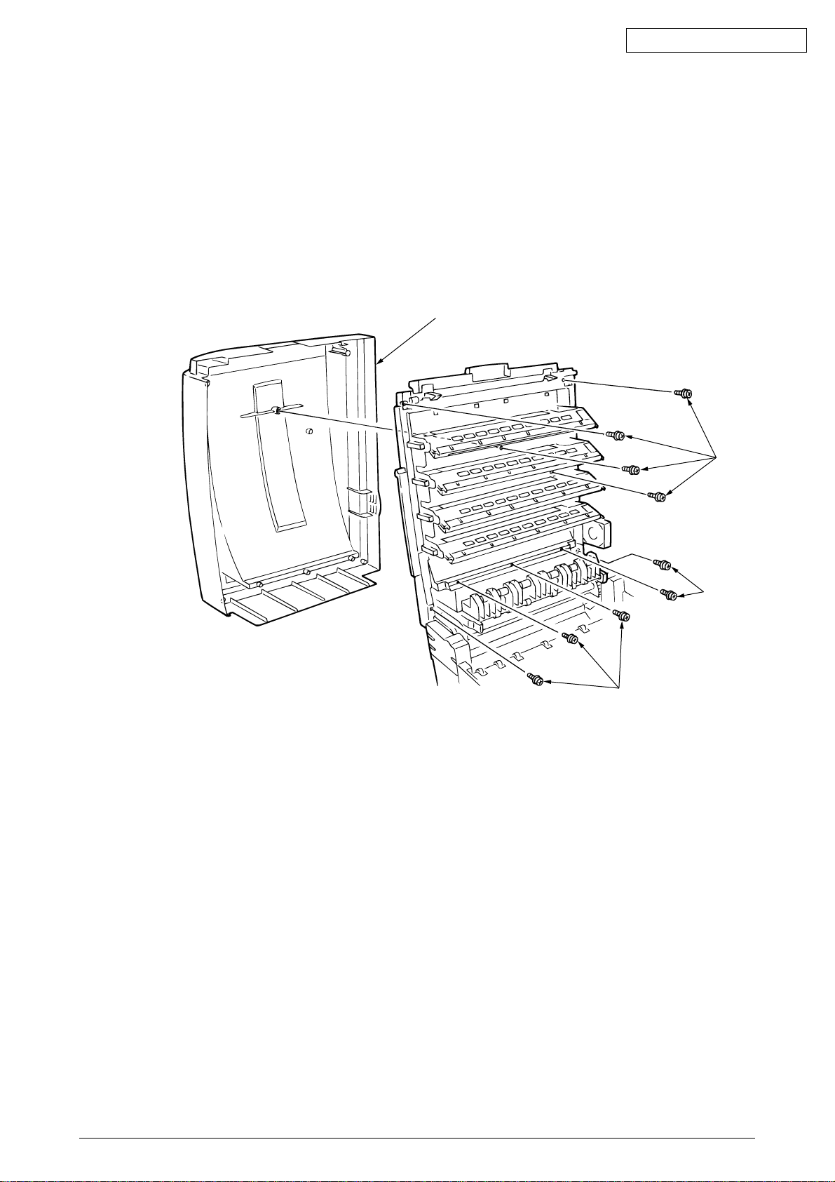
2.3.1 Top cover
(1) Open the top cover Assy.
(2) Remove the nine screws 1 to detach the top cover 2.
Oki Data CONFIDENTIAL
2
1
1
1
41388601TH Rev.6 21 /
Page 22
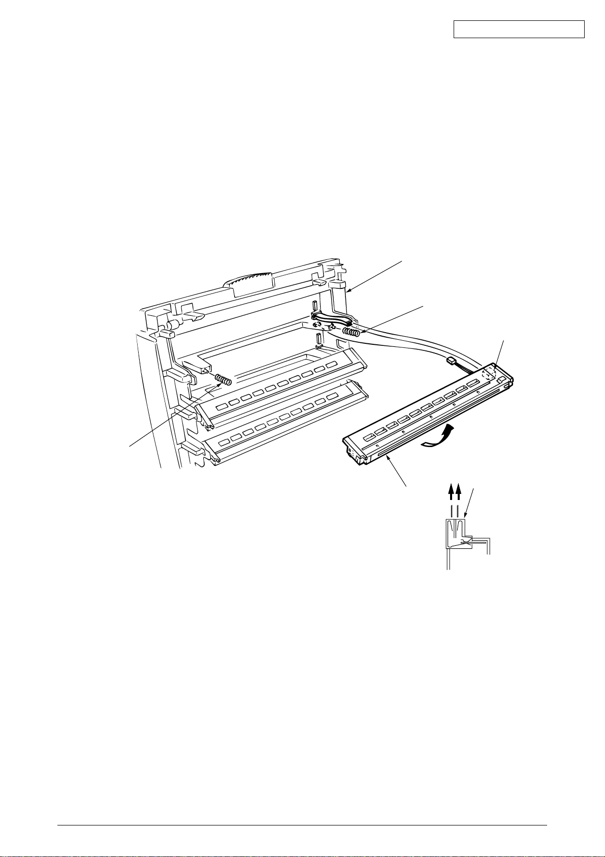
2.3.2 LED Assy/ LED Assy spring
(1) Open the top cove 1.
(2) Remove the three cables, and unhook the LED Assy 2 at the two places to demount it (The
two springs 3 become detached together with the LED Assy 2).
(3) Detach the LED connector 4.
When assembling, attach the LED connector 4 to the LED head and insert the flat cable.
Oki Data CONFIDENTIAL
1
3
3
4
4
2
41388601TH Rev.6 22 /
Page 23
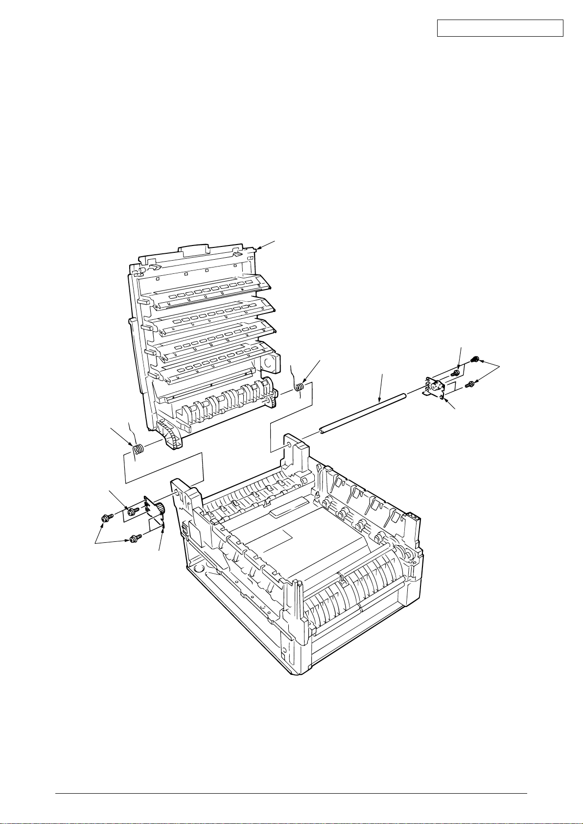
2.3.3 Top cover unit
(1) Remove the top cover (see section 2.3.1).
(2) Remove the rear cover (see section 2.3.12).
(3) Remove the front cover (see section 2.3.11).
(4) Remove the electrical chassis (see section 2.3.21).
(5) Unscrew the screws 1 and 2 to remove the limiters (F) 3 and (R) 4.
(6) Remove the inner shaft 5, then the top cover unit 8 (The inner springs 6 and 7 become
detached).
Oki Data CONFIDENTIAL
8
1
6
2
3
7
5
2
1
4
41388601TH Rev.6 23 /
Page 24
Oki Data CONFIDENTIAL
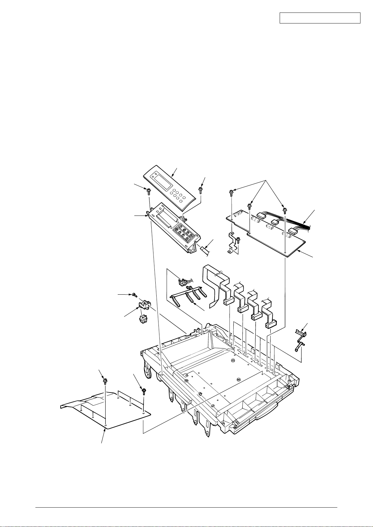
2.3.4 Control panel Assy/ Control panel bezel/ LED control PWB/ Toner sensor/ Stack full sensor/
Control panel tape harness/ Eject roller
(1) Detach the control panel bezel 1.
(2) Remove the screws 2 to demount the control panel 3.
(3) Detach the control panel tape harness 4.
(4) Remove the screws 6, unhook the connector 7 and demount the LED control PWB 8.
(5) Unscrew the screws 9 to remove the plate 0.
(6) Disengage the claw to demount the toner sensor A.
(7) Demount the stacker full sensor B.
(8) Unscrew the eject sensor bracket C, D.
1
2
6
2
9
C
D
7
3
4
8
B
A
9
0
41388601TH Rev.6 24 /
Page 25
2.3.5 Top cover handle/ Tope cover latch/ Top cover latch spring
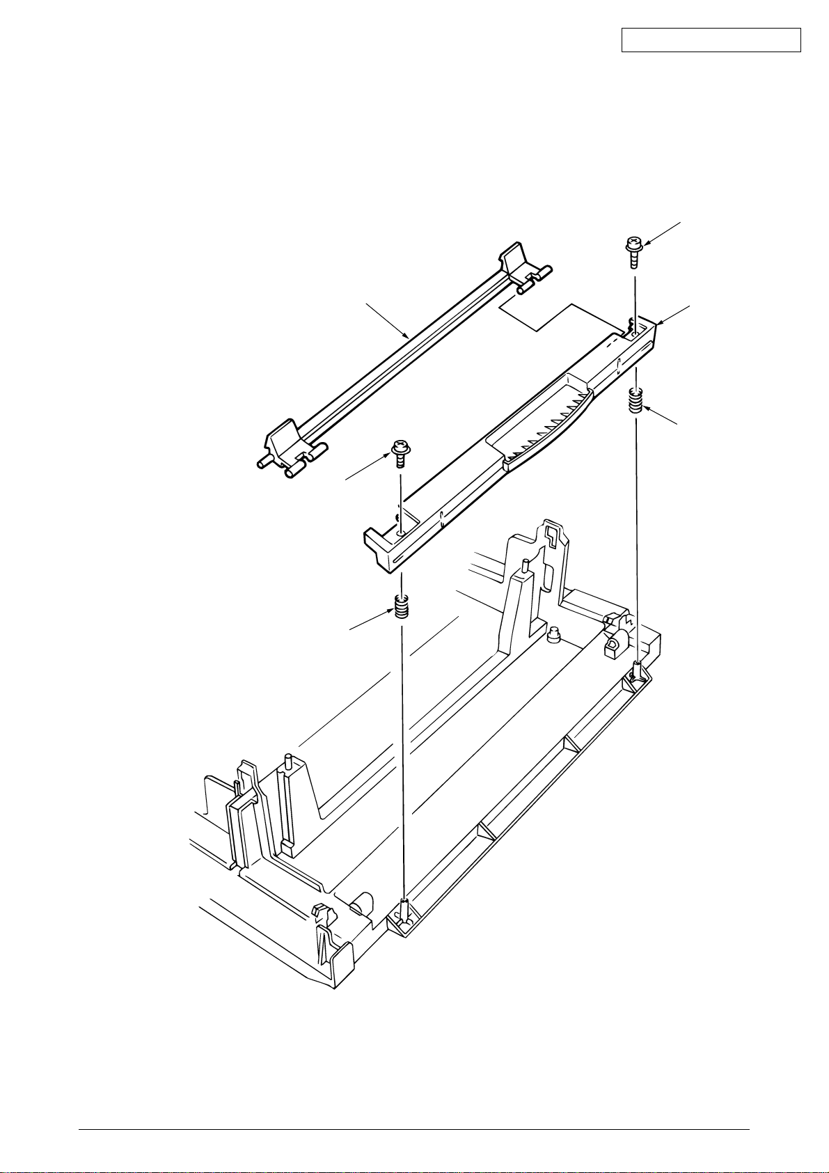
(1) Remove the two screws 1 to detach the top cover handle 2 and disengage the top cover
latch 3 (The two top cover latch springs 4 become detached).
Oki Data CONFIDENTIAL
1
1
4
3
2
4
41388601TH Rev.6 25 /
Page 26
2.3.6 Eject guide Assy
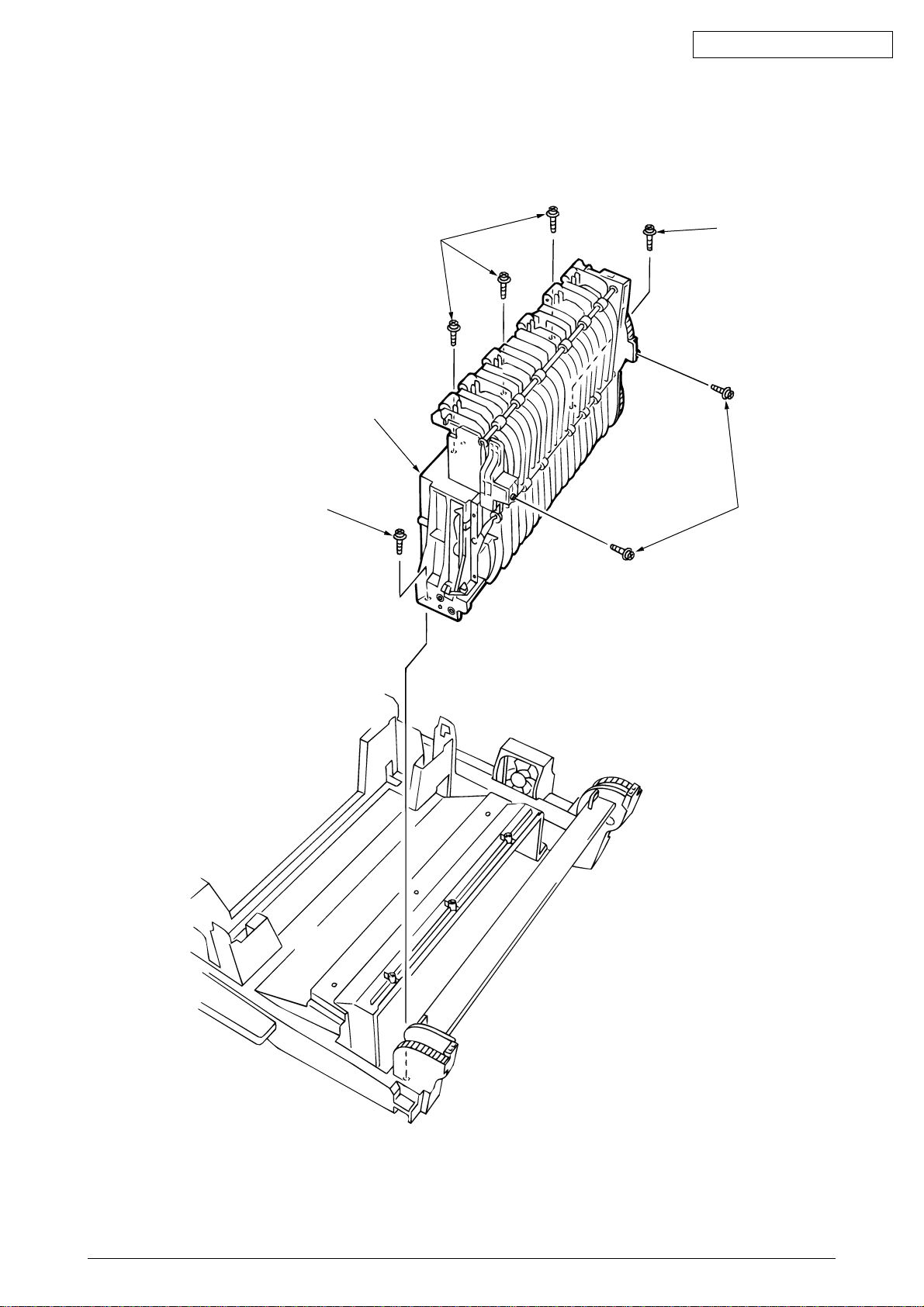
(1) Remove the seven screws 1 to detach the eject guide Assy 2.
Oki Data CONFIDENTIAL
1
2
1
1
1
41388601TH Rev.6 26 /
Page 27
2.3.7 Cassette Assy/ Blind cover/ Side cover R Assy
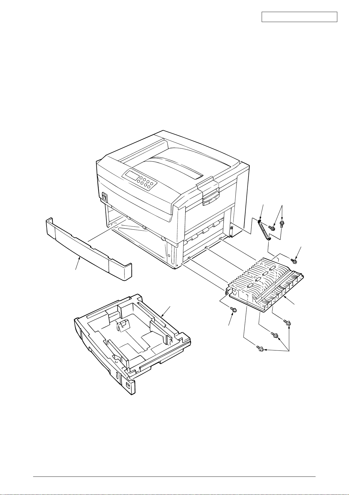
(1) Detach the cassette Assy 1.
(2) Disengage the blind cover 2 at the two places to detach it.
(3) Unscrew the two screws to remove the stopper 4.
(4) Disengage the claw on the left support of the side cover R to detach the side cover R.
Oki Data CONFIDENTIAL
2
1
5
4
5
5
3
5
41388601TH Rev.6 27 /
Page 28
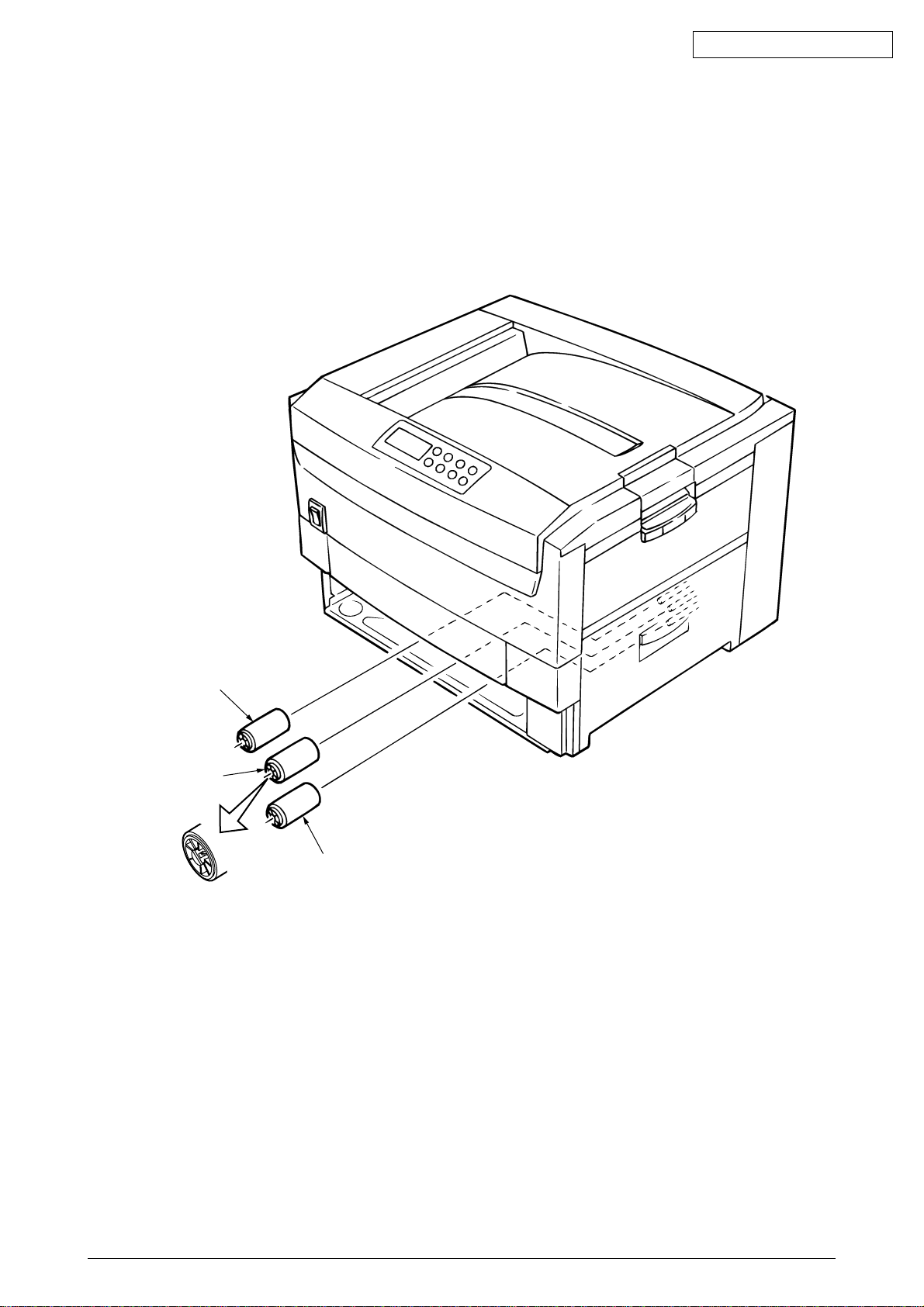
2.3.8 Feed rollers
(1) Remove the cassette.
(2) Unlatch and demount the feed rollers 1.
Oki Data CONFIDENTIAL
1
1
1
41388601TH Rev.6 28 /
Page 29
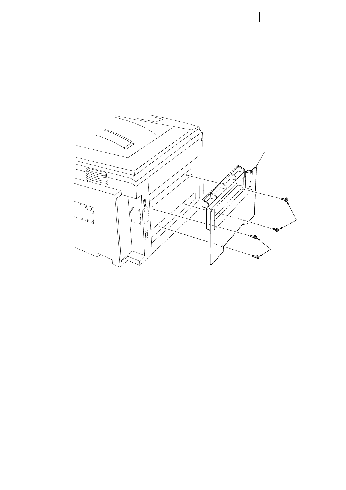
2.3.9 Left side cover
(1) Remove the four screws 1 to detach the left side cover 2.
Oki Data CONFIDENTIAL
2
1
1
41388601TH Rev.6 29 /
Page 30
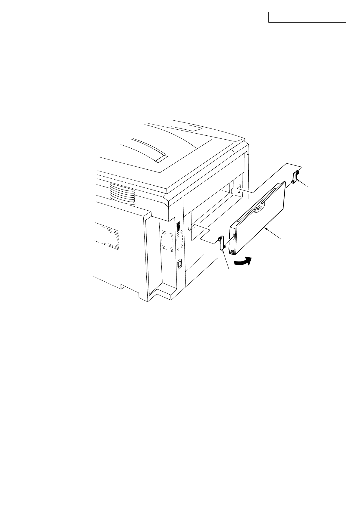
2.3.10 Face-up tray
(1) Open the face-up tray in the arrow direction and move the links 2 out of engagement (at two
places each of the links) to detach the face-up tray 1.
Oki Data CONFIDENTIAL
2
2
1
41388601TH Rev.6 30 /
Page 31
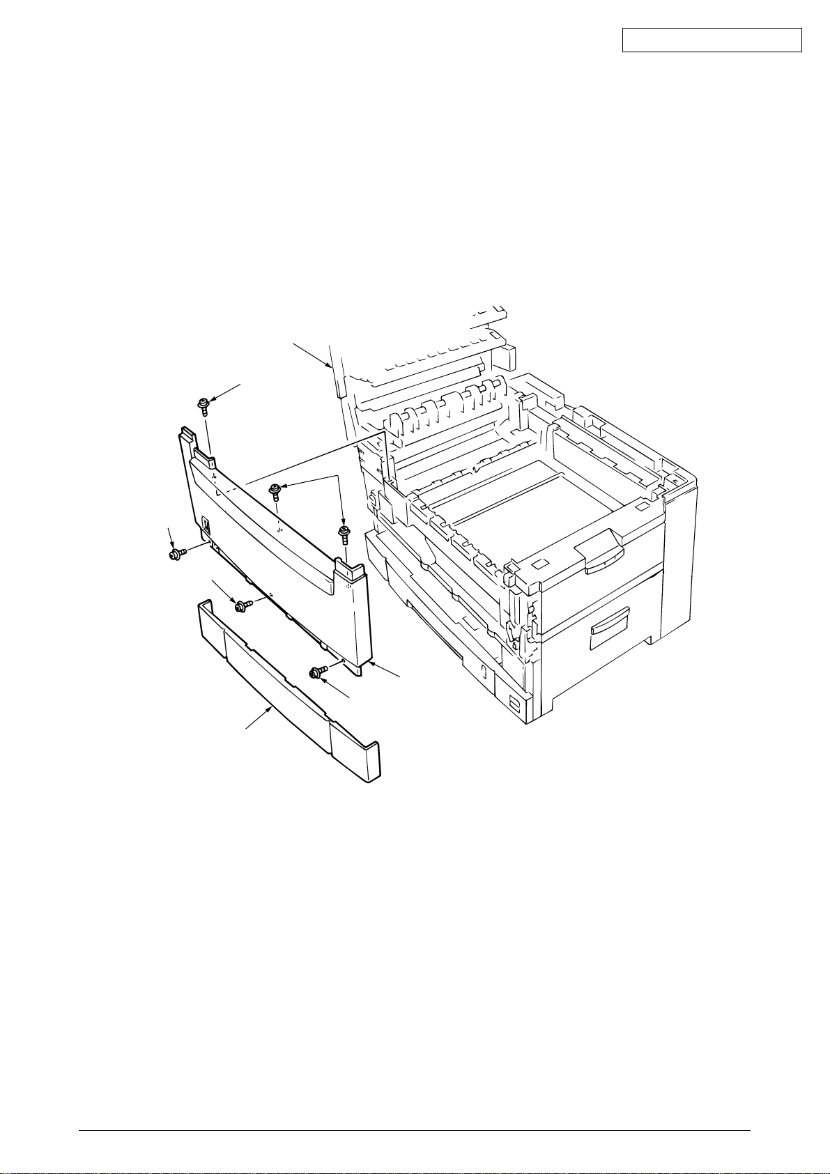
2.3.11 Front cover
(1) Open the top cover 1.
(2) Disengage the claws and remove the blind cover 2.
(3) Unscrew the six screws 4 to detach the front cover 3.
Oki Data CONFIDENTIAL
1
4
4
4
4
3
4
2
41388601TH Rev.6 31 /
Page 32
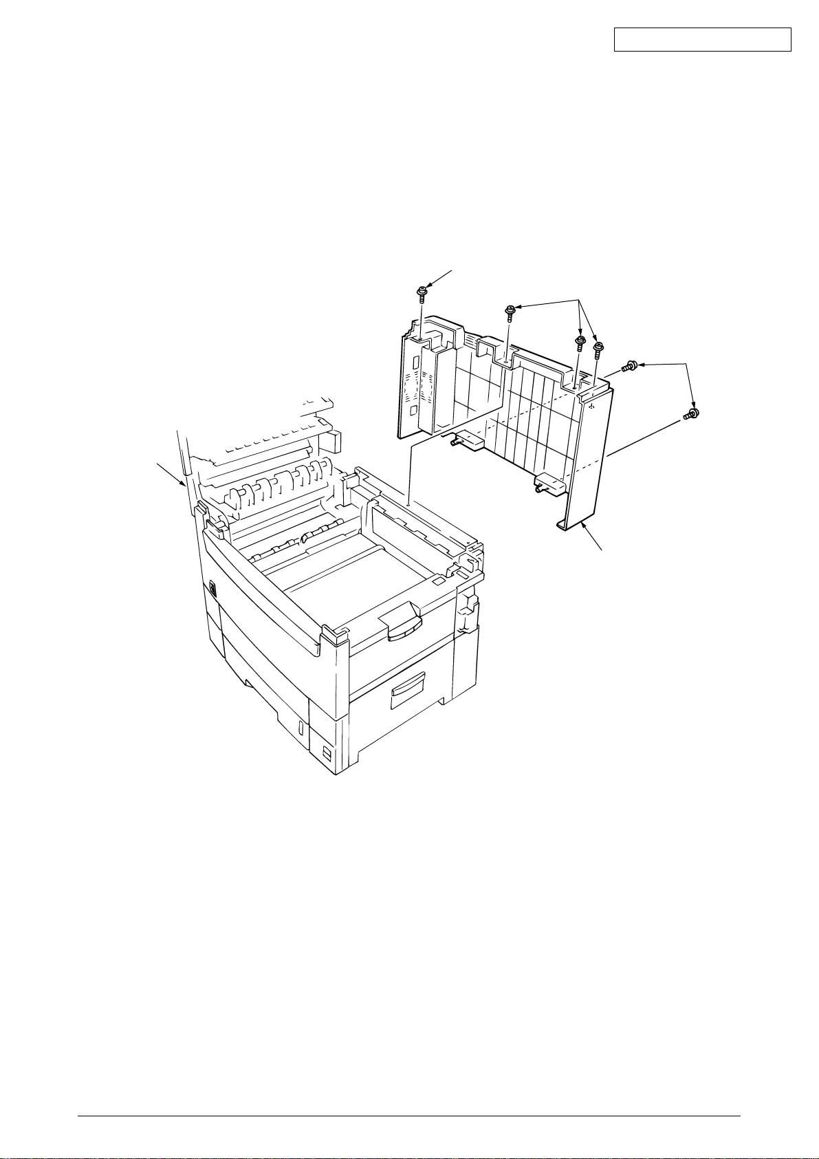
2.3.12 Rear cover
(1) Open the top cover 1,
(2) Remove the five screws 3 and 4 to detach the rear cover 2.
Oki Data CONFIDENTIAL
4
3
3
1
2
41388601TH Rev.6 32 /
Page 33
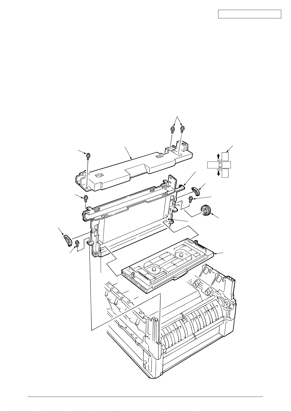
Oki Data CONFIDENTIAL
2.3.13 Multipurpose tray Assy/ Multipurpose tray cover Assy/ Links/ Multipurpose tray top cover/
Multipurpose tray drive gear
(1) Remove the rear cover (see section 2.3.12).
(2) Remove the front cover (see section 2.3.11).
(3) Unscrew the three screws 1 to detach the multipurpose tray top cover 2.
(4) Unscrew the two screws 3 and remove the connector to detach the multipurpose tray 4.
(5) Disengage 4 and 5 to detach the multipurpose tray cover Assy 5 (the links 7 become
detached).
(6) Unhook and detach the multipurpose tray drive gear 8.
1
6
3
5
1
Engagement
2
4
6
Engagement
8
3
8
5
41388601TH Rev.6 33 /
Page 34
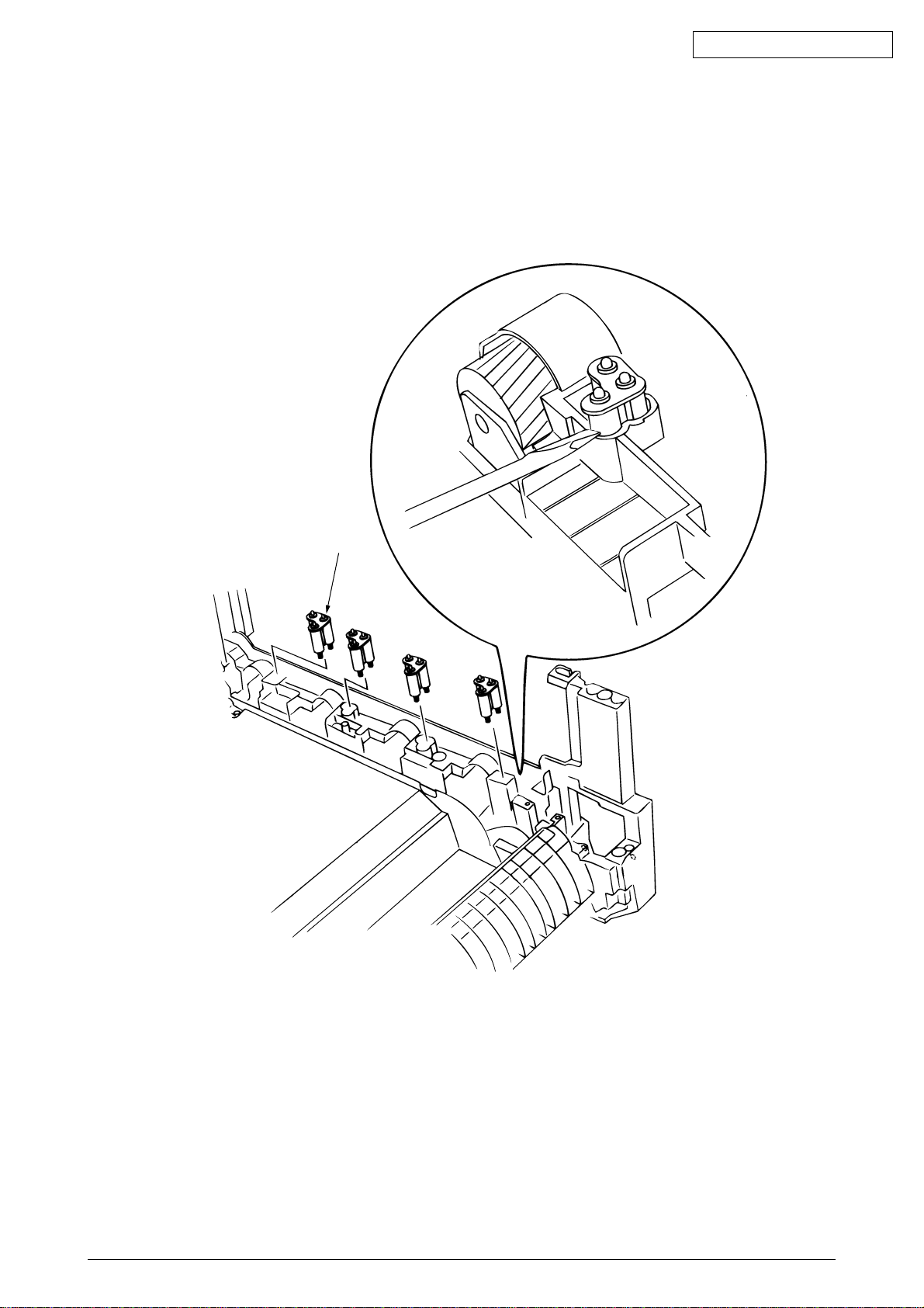
2.3.14 Drum contact Assys
(1) Insert a flatblade screwdriver between the printer case and the drum contact Assy 1 to
demount the drum contact Assy.
Oki Data CONFIDENTIAL
1
41388601TH Rev.6 34 /
Page 35
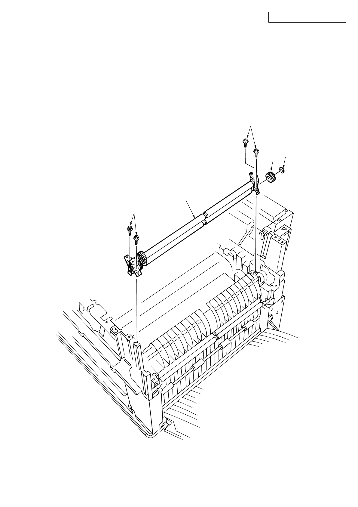
2.3.15 Registration roller Assy (A)/ Registration drive gear (A)
(1) Remove the front cover (see section 2.3.11).
(2) Remove the rear cover (see section 2.3.12).
(3) Remove the multipurpose tray (see section 2.3.13).
(4) Unscrew the four screws 1 to demount the registration roller Assy (A) 2.
(5) Remove the E ring 3 to detach the registration gear (A) 4.
1
Oki Data CONFIDENTIAL
3
4
1
2
41388601TH Rev.6 35 /
Page 36
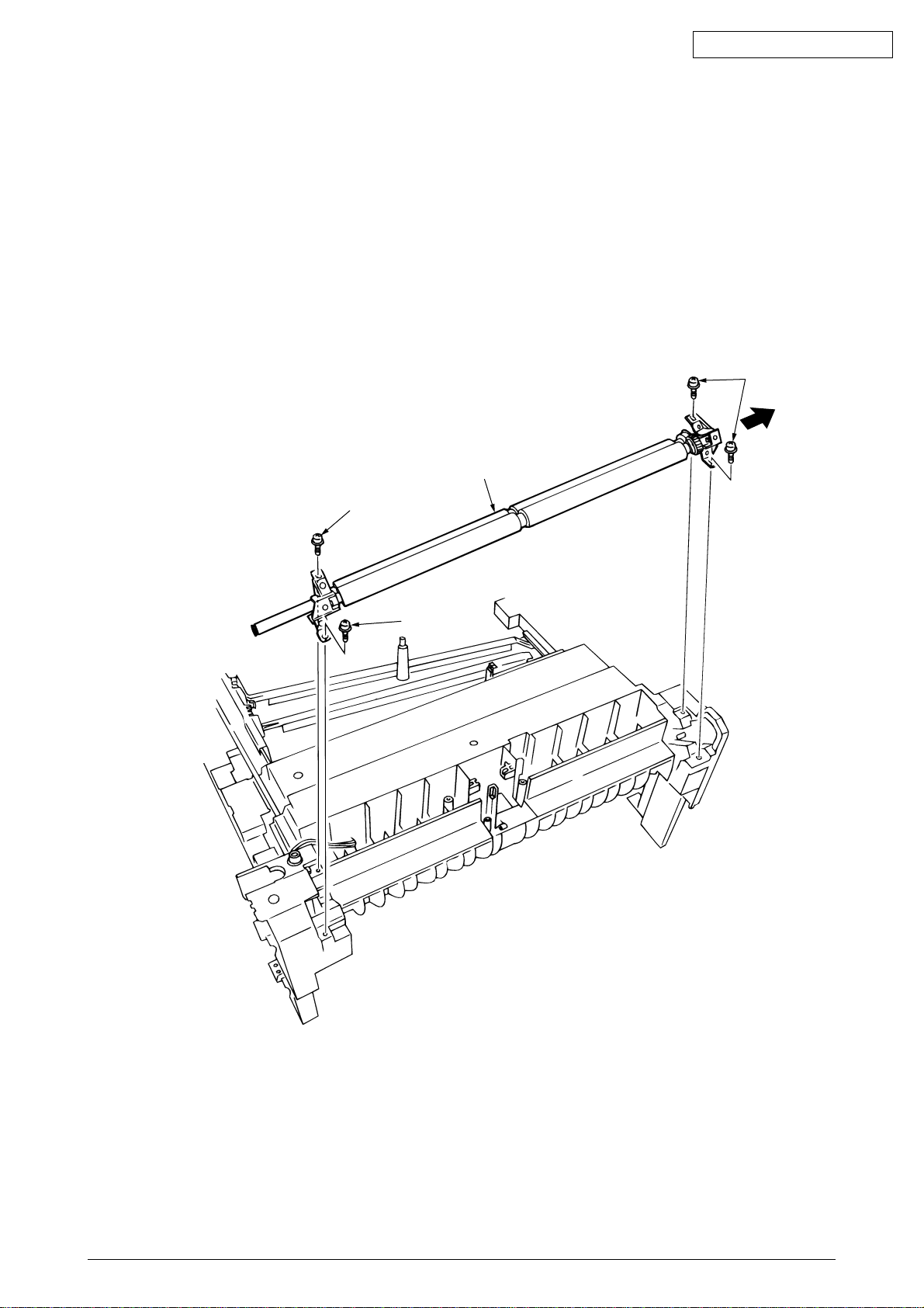
2.3.16 Registration roller Assy (B)
(1) Remove the cassette Assy.
(2) Remove the front cover (see section 2.3.11).
(3) Remove the rear cover (see section 2.3.12).
(4) Remove the electrical chassis (see section 2.3.21).
(5) Remove the registration clutch (see section 2.3.17).
(6) Remove the printer chassis (see section 2.3.23).
(7) Unscrew the four screws and pull out the registration Assy (B) 2 in the arrow direction.
Oki Data CONFIDENTIAL
1
2
1
1
41388601TH Rev.6 36 /
Page 37
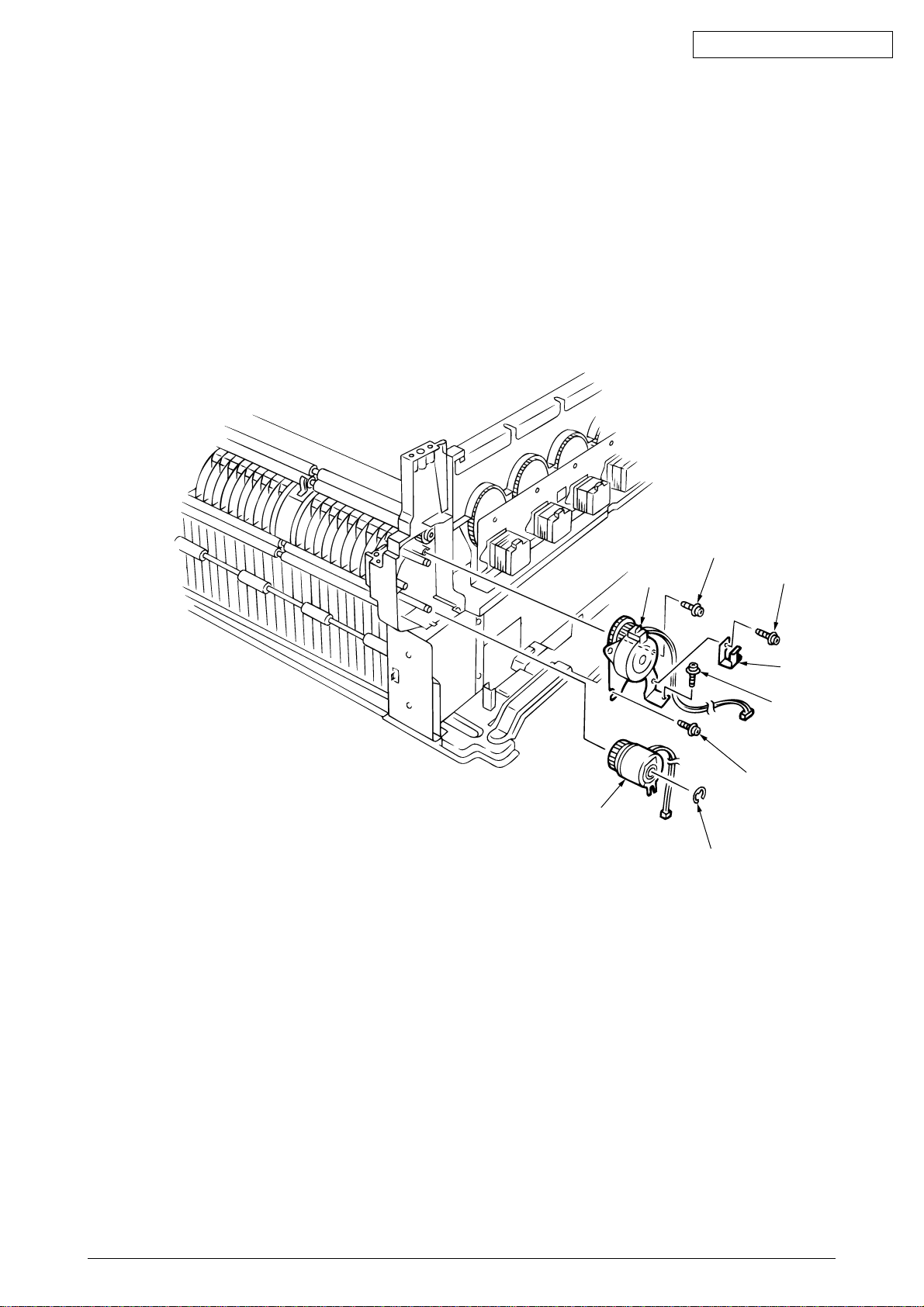
2.3.17 Registration clutch, Registration motor Assy
(1) Remove the left side cover (see section 2.3.9).
(2) Remove the electrical chassis (see section 2.3.21).
(3) Remove the connector and the E ring 1, then screws 3 and 4, and then the earth plate 5.
(4) Remove the connector and unscrew the two screws 6 to demount the registration motor Assy
7.
Oki Data CONFIDENTIAL
2
7
6
3
5
4
6
1
41388601TH Rev.6 37 /
Page 38
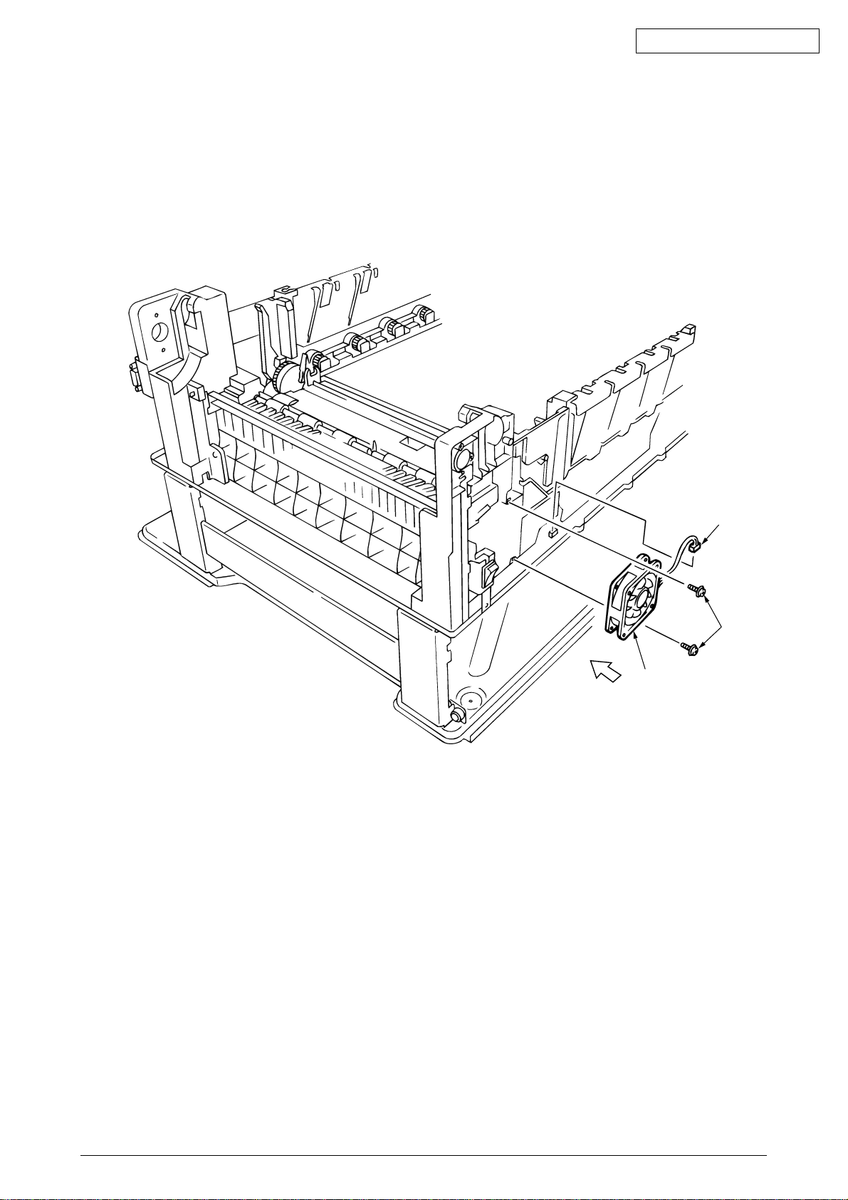
2.3.18 Cooling fan
(1) Unhook the connector 1, and remove the screws 2 and the cooling fan 3.
Oki Data CONFIDENTIAL
air direction
1
2
3
41388601TH Rev.6 38 /
Page 39
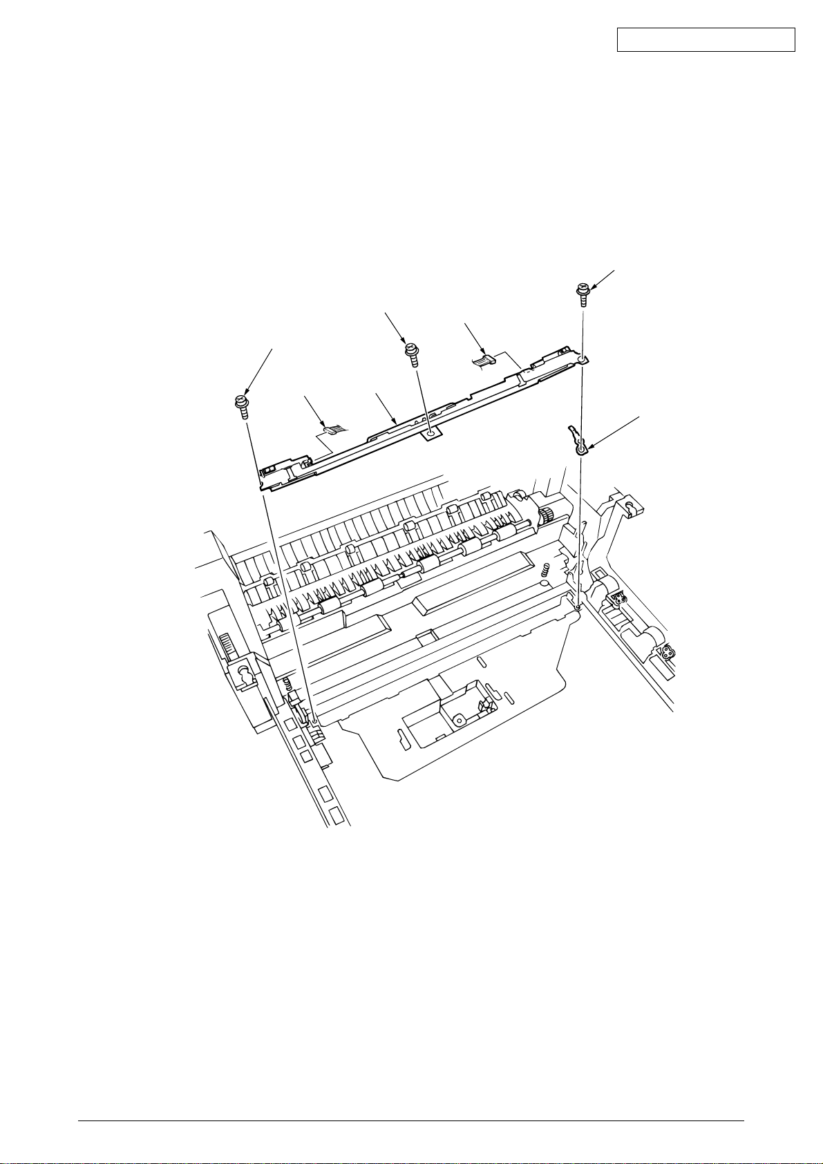
2.3.19 Color registration sensor Assy
(1) Remove the two screws 1 and the three connectors to demount the color registration sensor
Assy 2.
(2) Remove the earth plate B 3.
Oki Data CONFIDENTIAL
1
1
2
3
1
2
4
41388601TH Rev.6 39 /
Page 40
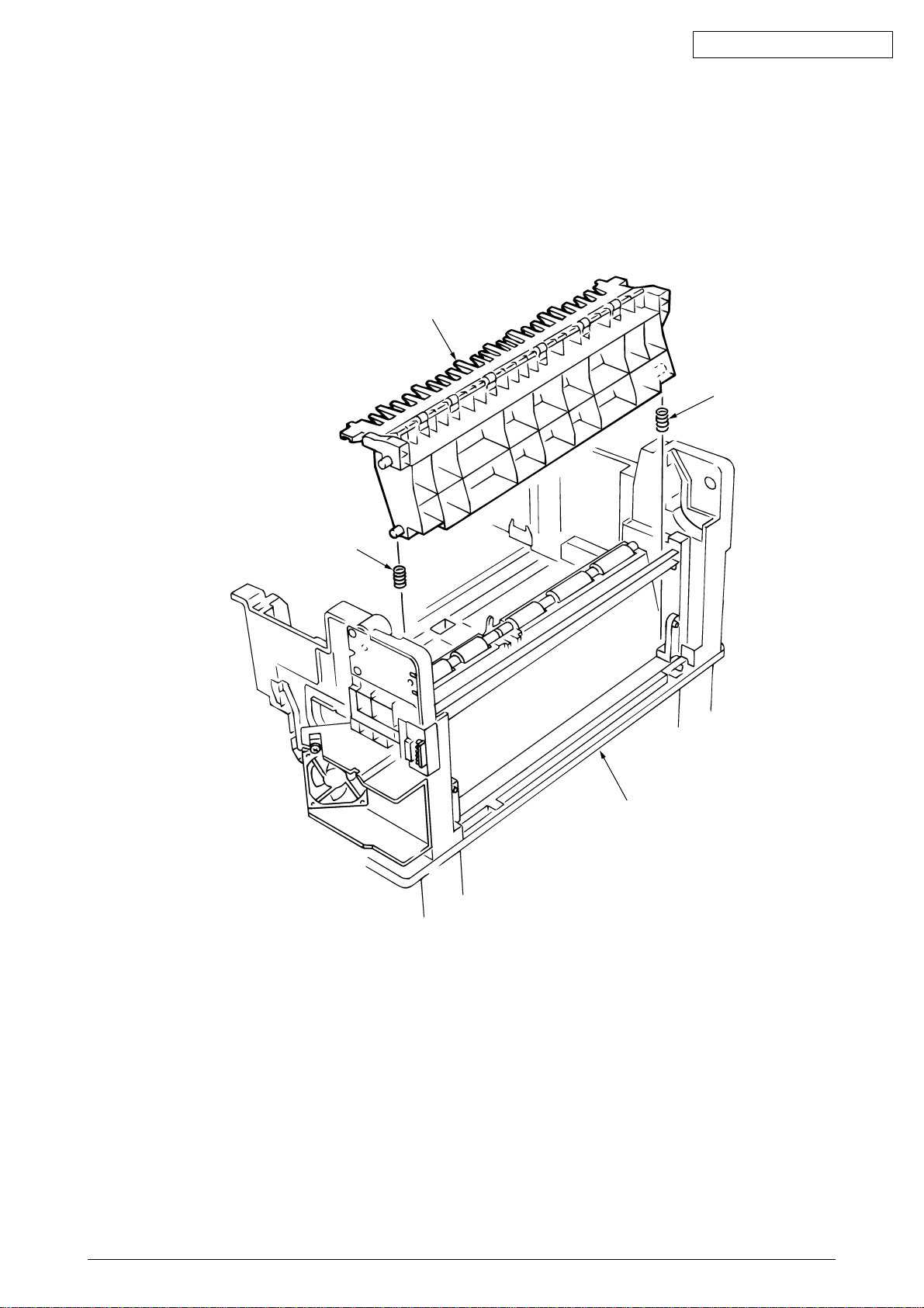
2.3.20 Duplex guide Assy
(1) Unlatch and demount the duplex guide Assy 1.
(2) Remove the springs 2.
Oki Data CONFIDENTIAL
1
2
2
Main chassis (L side)
41388601TH Rev.6 40 /
Page 41
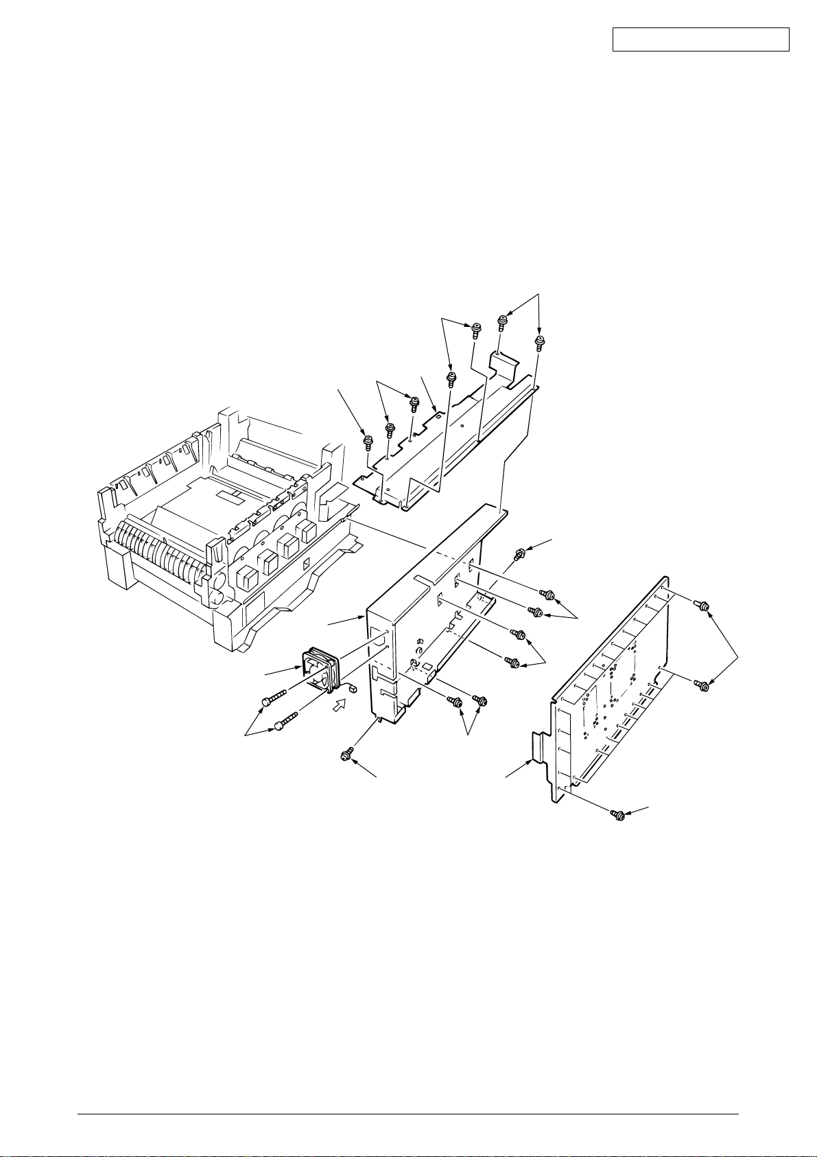
2.3.21 Electrical chassis/ Electrical chassis cooling fan
(1) Unscrew the five screws 1 and two screws 2 to remove the plate A 3.
(2) Unscrew the thirty-one screws 4 to remove the shield plate B 5.
(3) Remove the printer engine controller PWB (see section 2.3.22).
(4) Unscrew the eleven screws 6 to detach the electrical chassis 7.
(5) Unscrew the two screws 8 to demount the electrical chassis cooling fan 9.
Oki Data CONFIDENTIAL
1
1
8
9
1
7
air direction
2
3
6
6
6
6
4
6
5
4
41388601TH Rev.6 41 /
Page 42
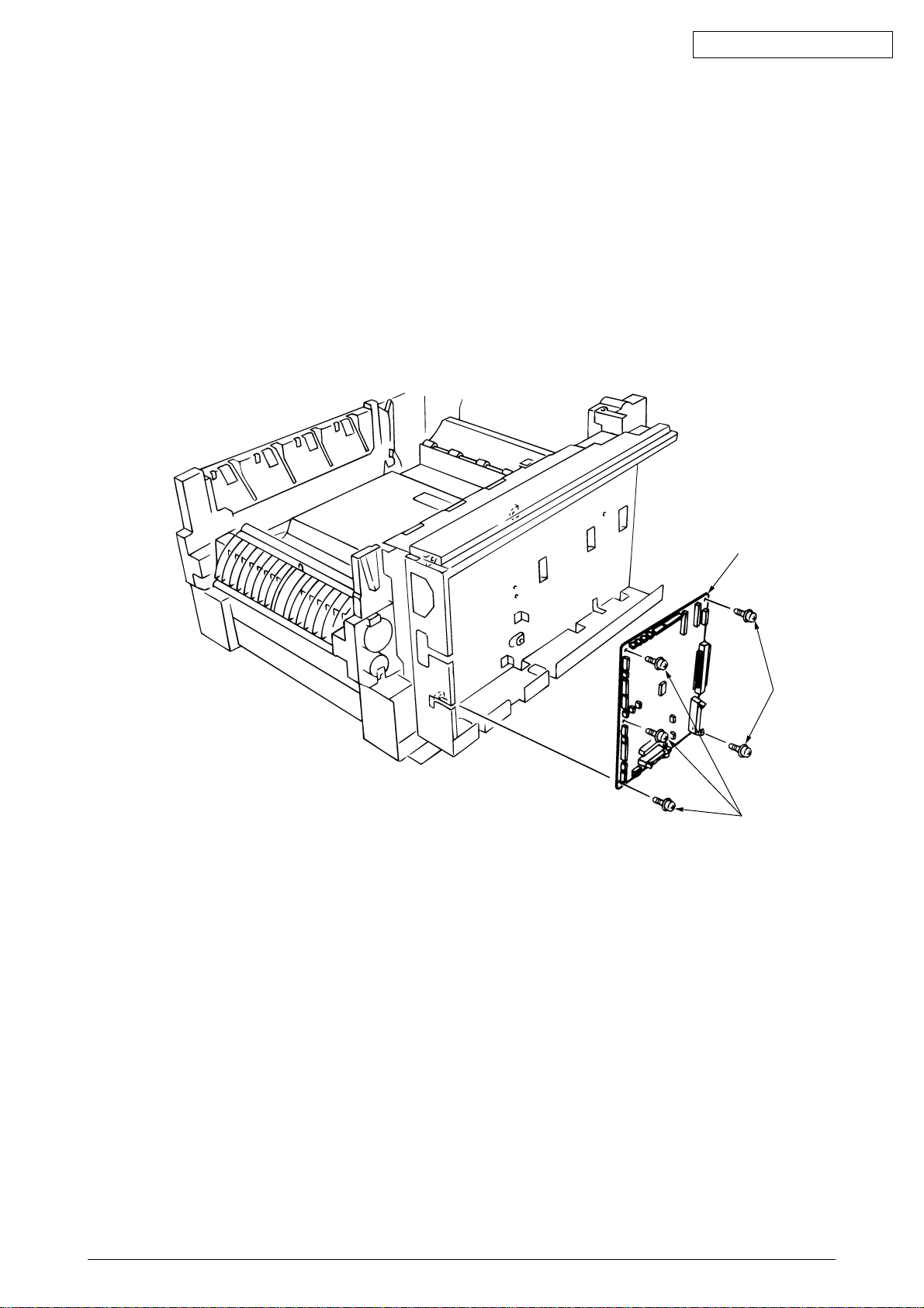
1
2.3.22 Printer engine controller PWB
(1) Remove the rear cover (see section 2.3.12).
(2) Remove the electrical chassis and the electrical cooling fan (see section 2.3.21).
(3) Remove the five screws 1 and all the connectors to demount the printer engine controller
PWB 2.
Oki Data CONFIDENTIAL
2
1
41388601TH Rev.6 42 /
Page 43
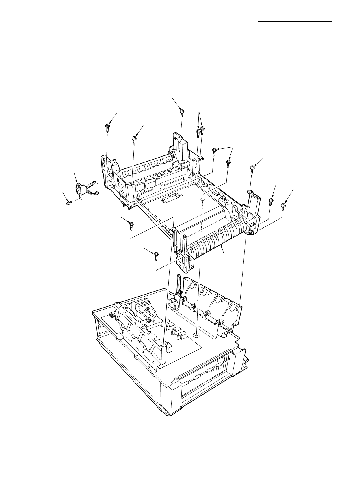
2.3.23 Printer unit chassis
(1) Unscrew the screw 1 and remove the AC switch Assy 2.
(2) Remove the four black screws 3 and six screws 4 to detach the printer unit chassis 5.
Oki Data CONFIDENTIAL
3
1
2
3
4
3
4
4
5
4
4
3
3
41388601TH Rev.6 43 /
Page 44
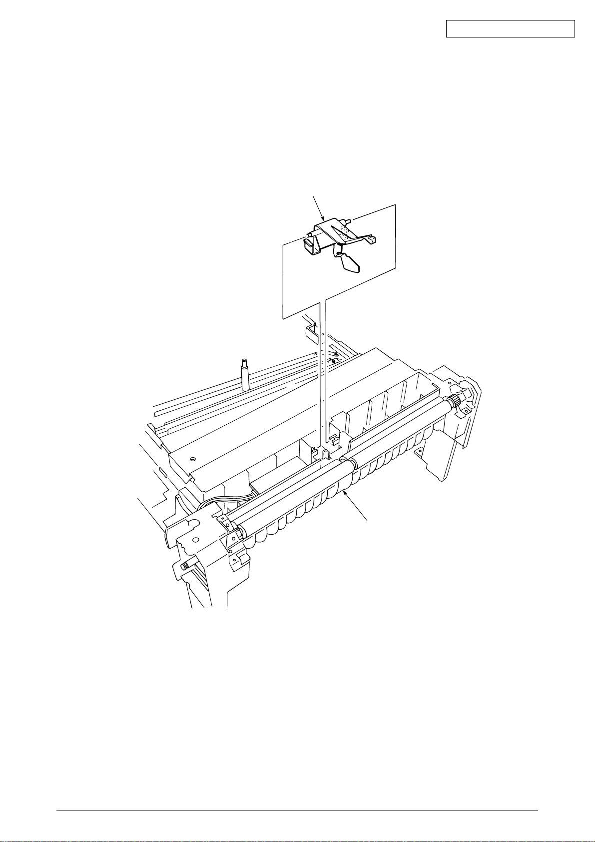
2.3.24 Entrance cassette sensor actuator
(1) Remove the printer unit chassis (see section 2.3.12).
(2) Turn over the main chassis.
(3) Remove the two clamps with tweezers to demount the entrance cassette sensor actuator 1.
Oki Data CONFIDENTIAL
1
Main chassis
41388601TH Rev.6 44 /
Page 45
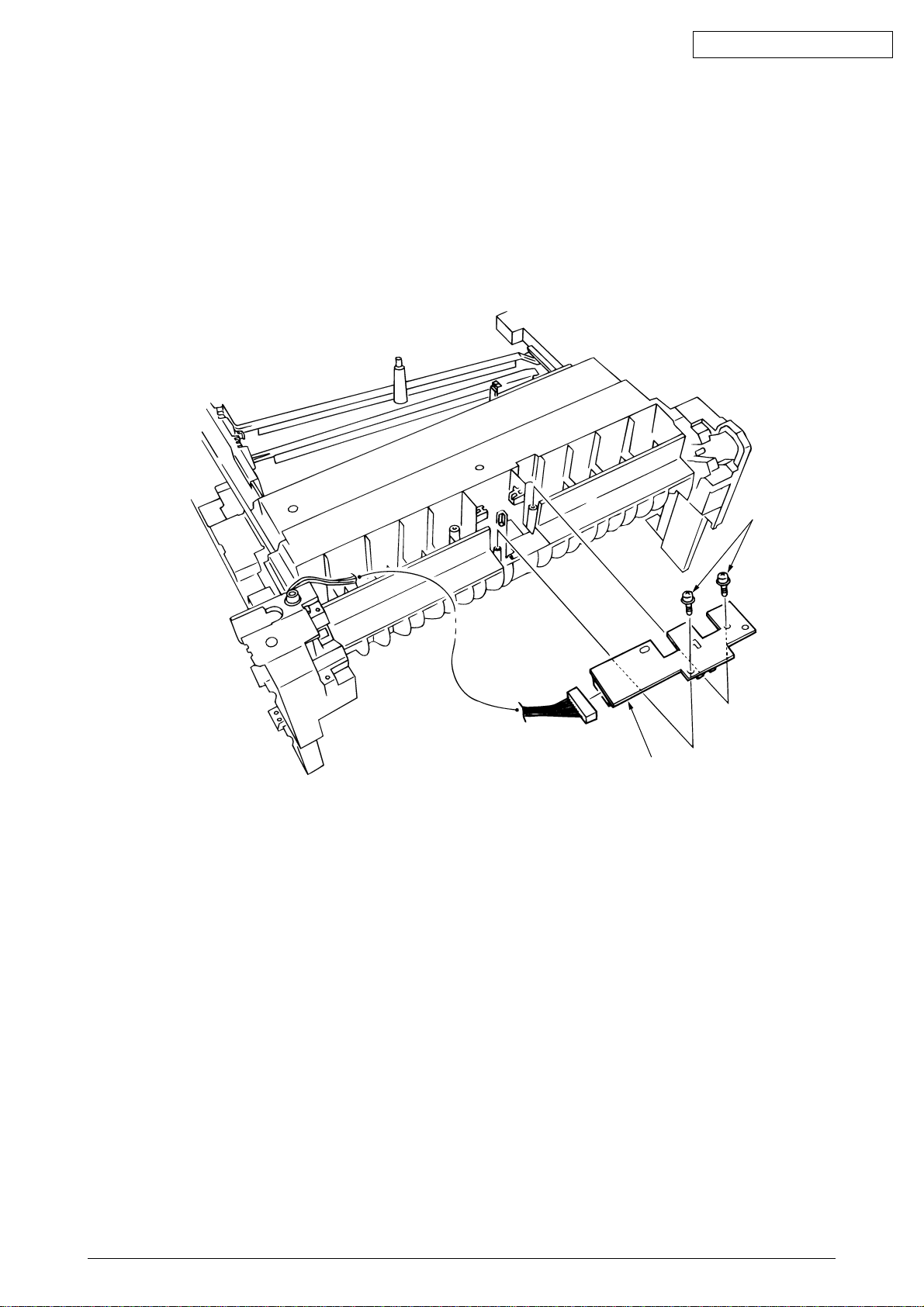
2.3.25 Entrance sensor PWB
(1) Remove the registration roller Assy (B) (see section 2.3.16).
(2) Remove the two screws 1 to demount the entrance sensor PWB 2.
Oki Data CONFIDENTIAL
2
1
41388601TH Rev.6 45 /
Page 46
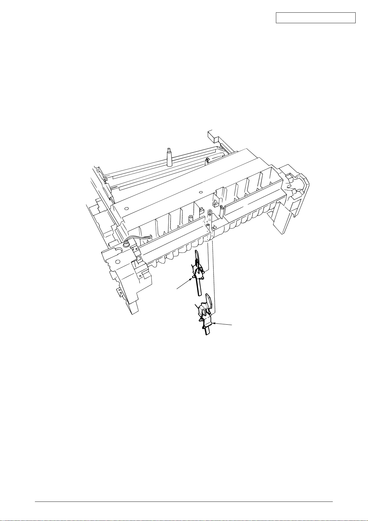
2.3.26 Entrance MT sensor actuator and Entrance belt sensor actuator
(1) Remove the entrance sensor PWB (R71) (see section 2.3.25).
(2) Unlatch and detach the entrance MT sensor actuator 1.
(3) Unlatch and detach the entrance belt actuator 2.
Oki Data CONFIDENTIAL
2
1
41388601TH Rev.6 46 /
Page 47
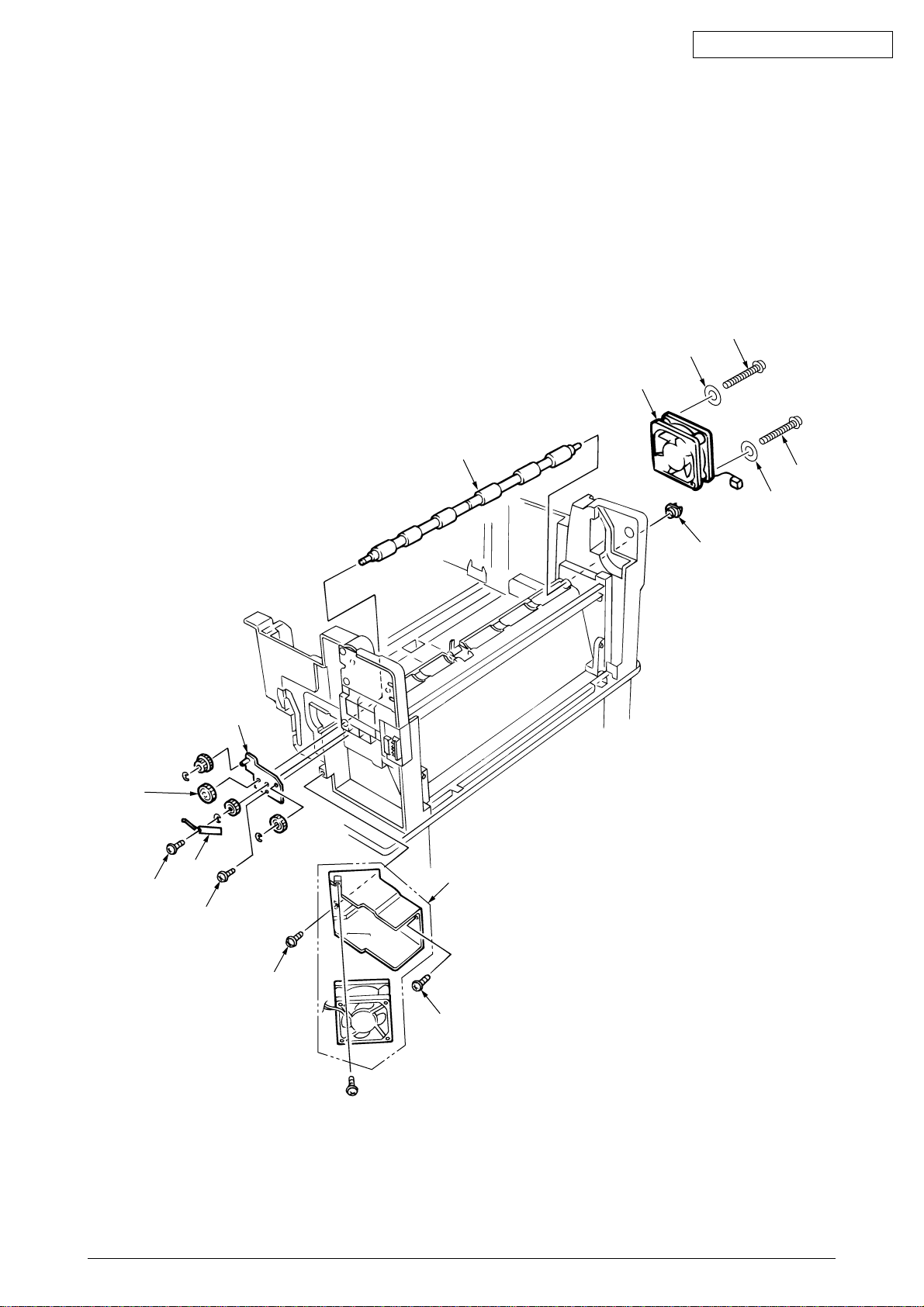
2.3.27 Main motor fan/ Fuser eject roller
(1) Unscrew the two screws 1 to remove the fan Assy 2.
(2) Unscrew the fuser eject roller contact 4.
(3) Remove the fuser drive gear 5.
(4) Unscrew the fuser drive gear Assy 8.
(5) Remove the screws and washers 0 to demount the fan A.
(6) Unlatch and detach the fuser eject roller bearing (L) B and fuser eject roller C.
Oki Data CONFIDENTIAL
9
0
A
C
9
5
3
4
0
B
8
2
7
1
1
41388601TH Rev.6 47 /
Page 48
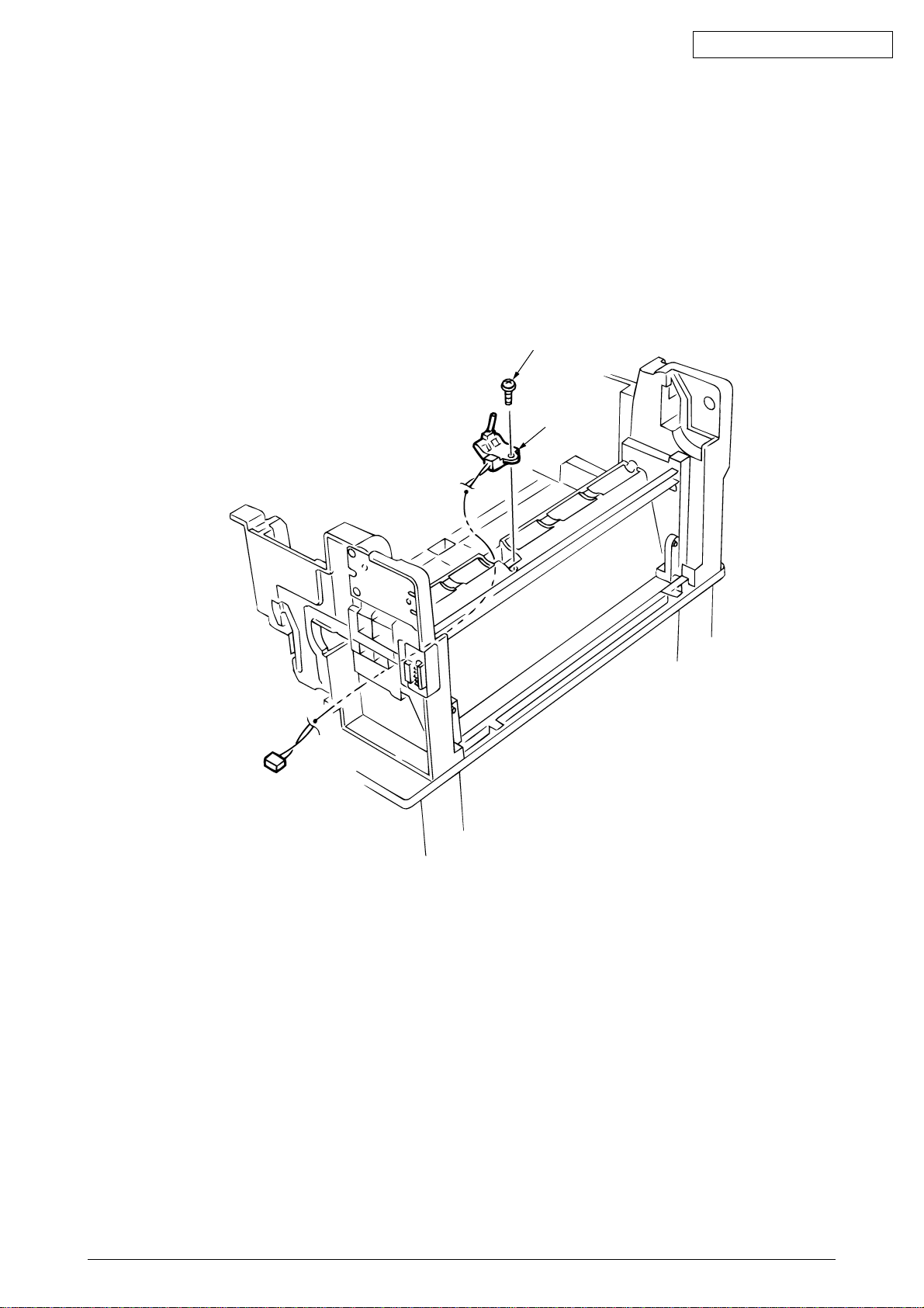
2.3.28 Eject sensor Assy
(1) Remove the fuser eject roller (see section 2.3.27).
(2) Remove the screw 1 and connector 2 to demount the (red/blue) eject sensor Assy 2.
Oki Data CONFIDENTIAL
1
2
41388601TH Rev.6 48 /
Page 49
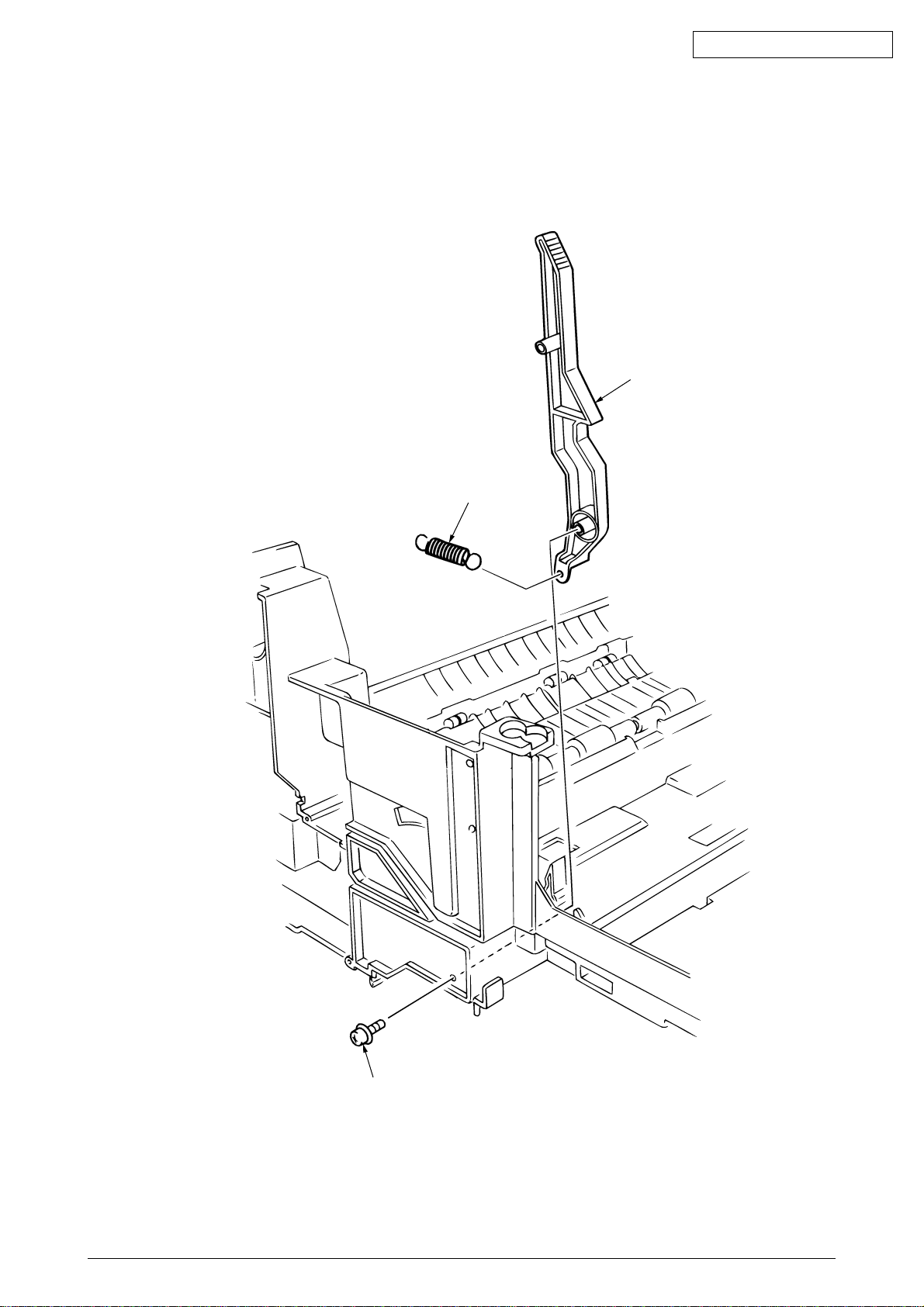
2.3.29 Fuser latching handle (L)
(1) Remove the latching handle spring 1.
(2) Unscrew the fuser latching handle (L) 2, 3.
Oki Data CONFIDENTIAL
3
1
2
41388601TH Rev.6 49 /
Page 50
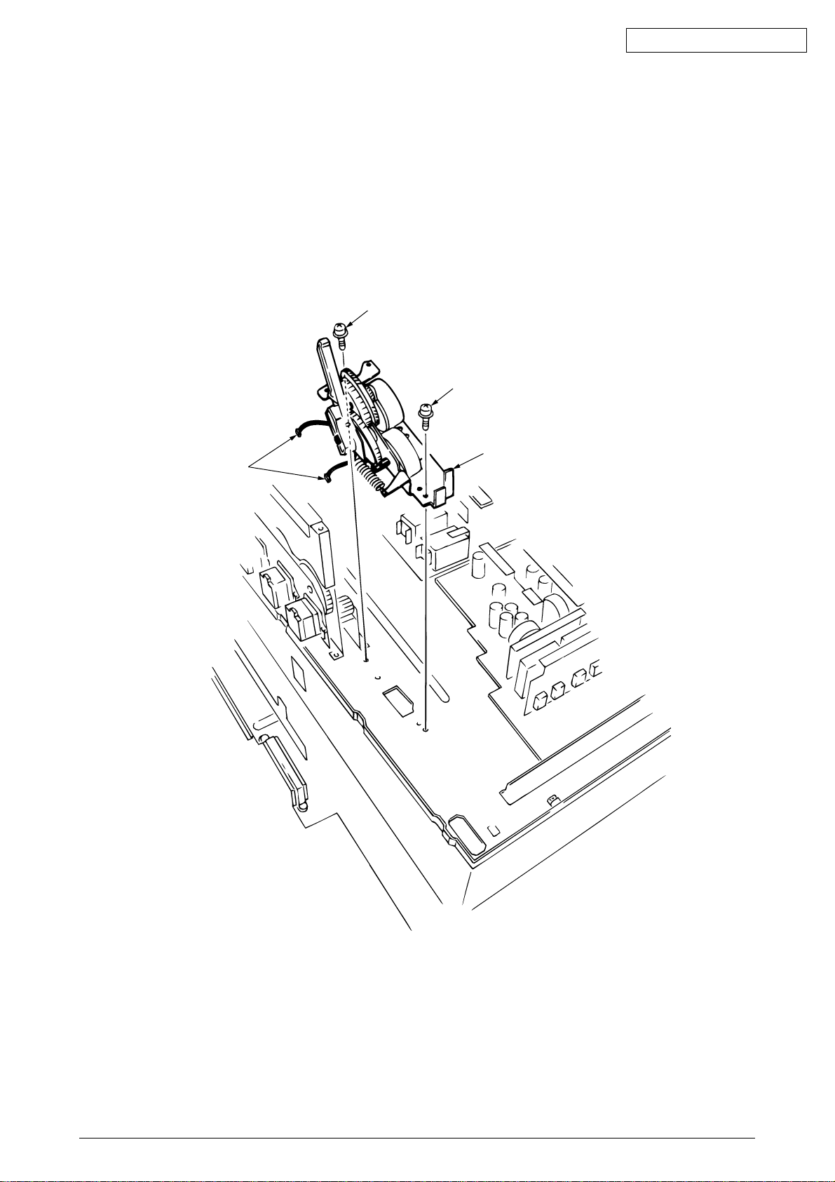
2.3.30 Belt motor Assy
(1) Remove the fuser latching handle (R) (see section 2.3.21).
(2) Unscrew the two screws 1 to detach the two connector 2.
(3) Demount the belt motor Assy 3.
Oki Data CONFIDENTIAL
1
1
2
3
41388601TH Rev.6 50 /
Page 51
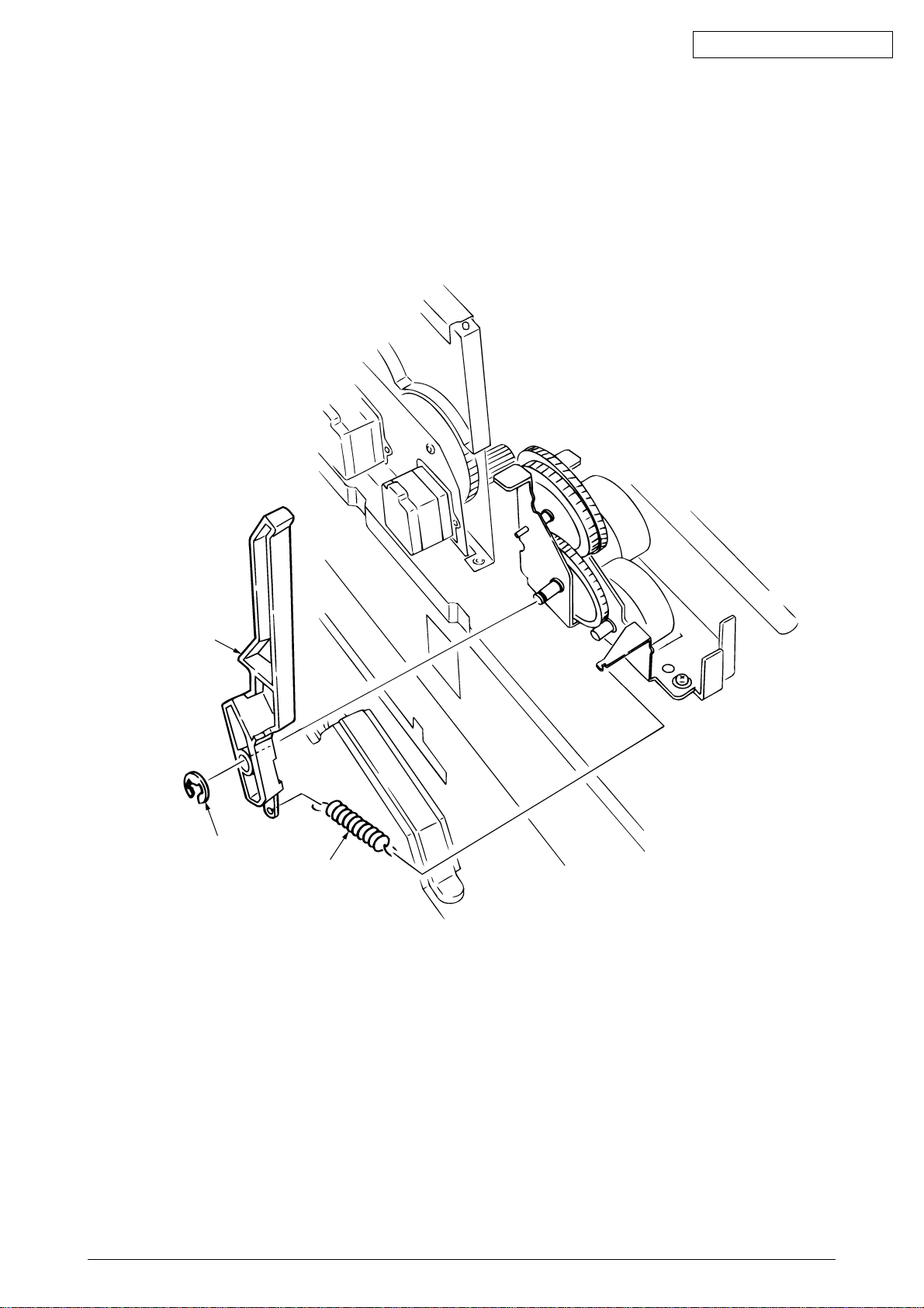
2.3.31 Fuser latching handle (R)
(1) Remove the printer unit chassis (see section 2.3.23).
(2) Remove the E ring 1.
(3) Remove the fuser latching handle spring 2 to detach the fuser latching handle (R) 3.
Oki Data CONFIDENTIAL
3
1
2
41388601TH Rev.6 51 /
Page 52
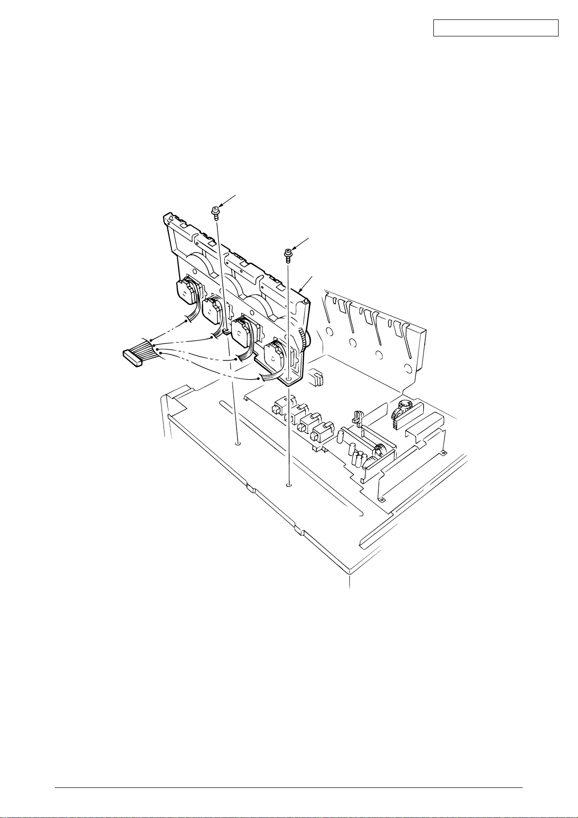
2.3.32 Main motor Assy
(1) Remove the belt motor Assy (see section 2.3.30).
(2) Remove all the connector.
(3) Remove the two screws 1 to demount the main motor Assy 2.
Oki Data CONFIDENTIAL
1
1
2
41388601TH Rev.6 52 /
Page 53
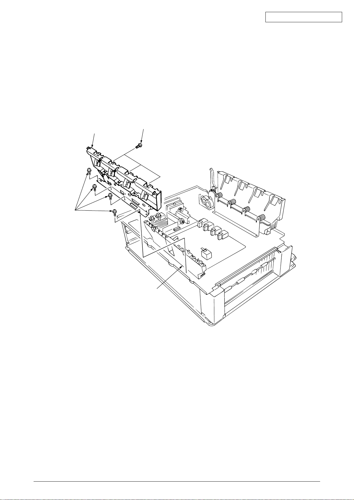
2.3.33 Contact Assy/ Side plate Assy
(1) Remove the printer unit chassis (see section 2.3.23).
(2) Remove the four screws 1 to detach the side plate Assy 2.
(3) Remove the three screws 3 to detach the contact Assy 4.
Oki Data CONFIDENTIAL
1
2
3
4
41388601TH Rev.6 53 /
Page 54

2.3.34 Low voltage power supply
(1) Remove the printer unit chassis (see section 2.3.23).
(2) Unhook the connector 1.
(3) Remove the eight screws 2 to demount the low voltage power supply 5.
Oki Data CONFIDENTIAL
0
2
0
1
0
2
2
7
8
6
3
5
B
A
9
41388601TH Rev.6 54 /
Page 55
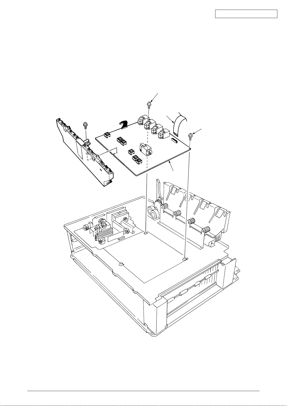
2.3.35 High voltage power supply
(1) Remove the contact Assy (see section 2.3.33).
(2) Unhook the connector of the high voltage power supply 1.
(3) Remove the two screws 2 to detach the high voltage power supply 1 and the tape harness
3.
Oki Data CONFIDENTIAL
2
3
2
1
41388601TH Rev.6 55 /
Page 56
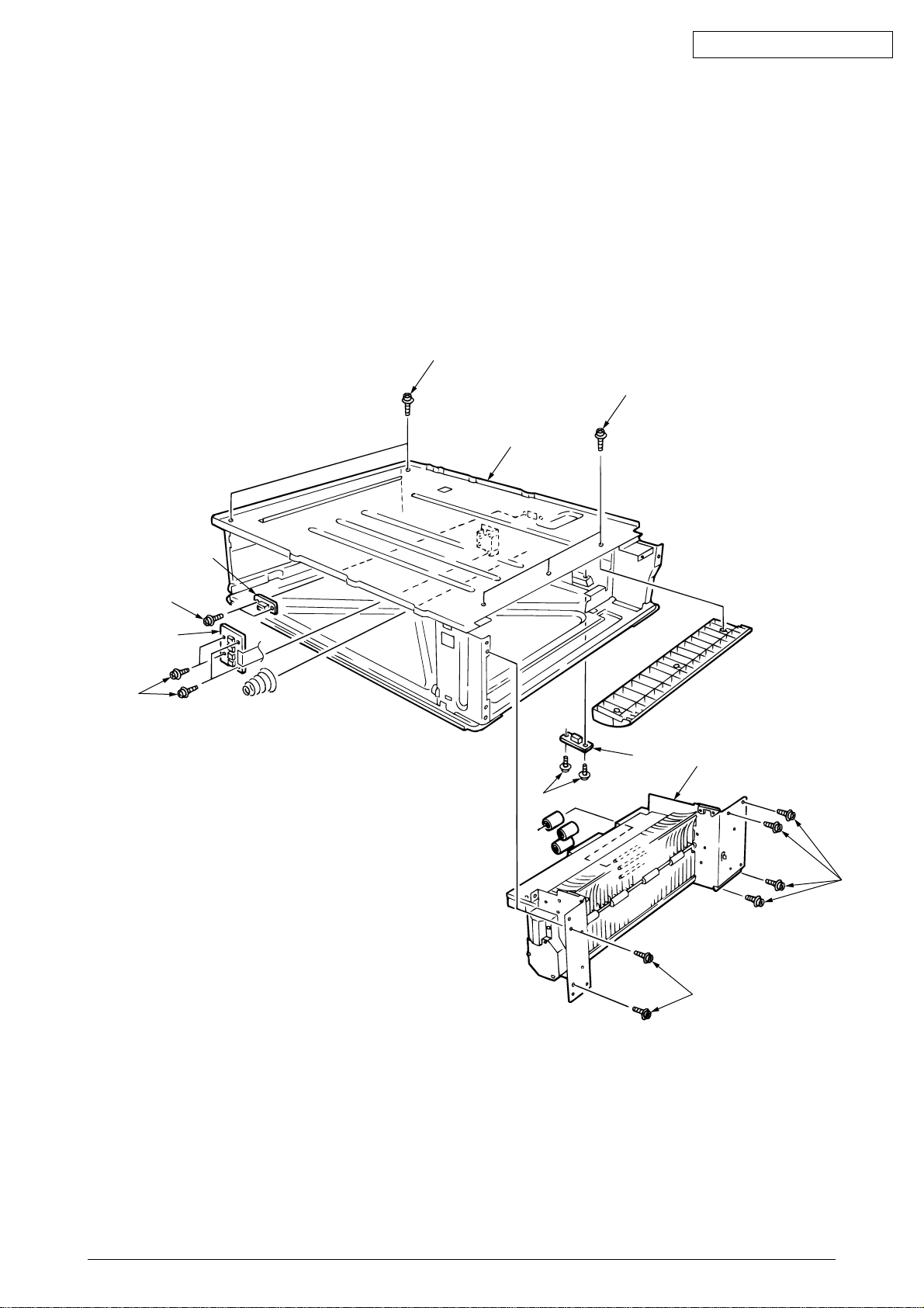
2.3.36 Main feed Assy
(1) Remove the printer unit chassis (see section 2.3.23).
(2) Remove the low voltage power supply and high voltage power supply (see sections 2.3.34
and 2.3.35).
(3) Unscrew the five screws 1 to remove the lower plate 2.
(4) Unscrew the six screws 3 to demount the main feed Assy 4.
(5) Unscrew the screws 5 to detach the cable and then the PCB size board 6.
(6) Unscrew the screw 7 to detach the duplex connector 8.
(7) Unscrew the screws 9 to detach the second tray connector 0.
Oki Data CONFIDENTIAL
1
1
2
5
7
6
8
9
0
4
3
3
41388601TH Rev.6 56 /
Page 57
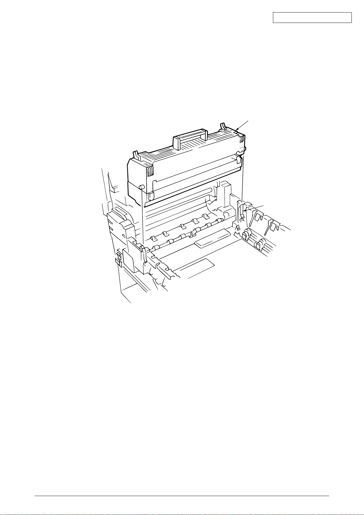
2.3.37 Fuser unit
(1) Open the top cover 1.
(2) Push the right and left fuser levers (blue) 2 in the arrow direction to detach the fuser unit 3.
Oki Data CONFIDENTIAL
3
2
41388601TH Rev.6 57 /
Page 58
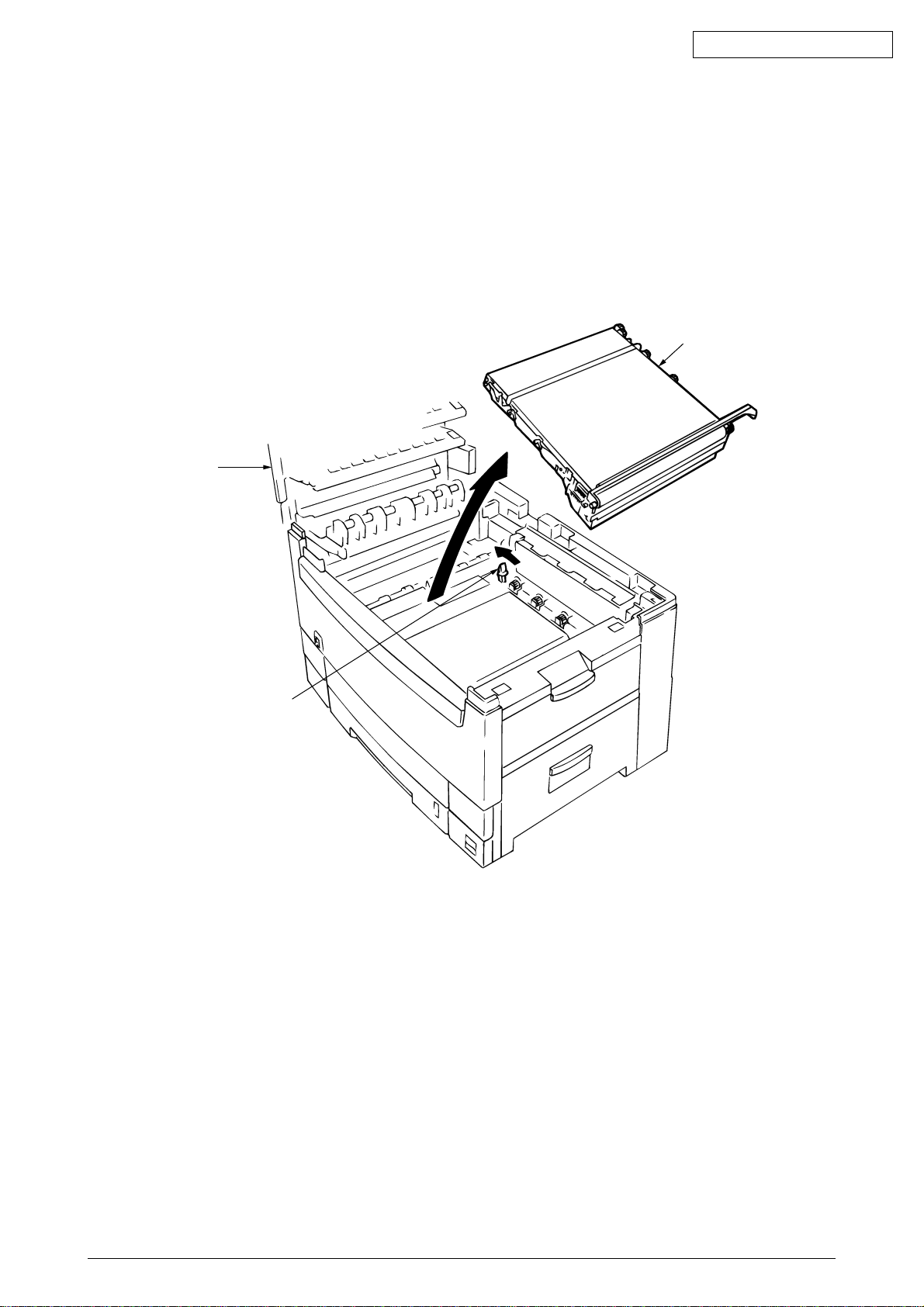
2.3.38 Belt unit
(1) Open the top cover 1.
(2) Remove the I/D unit.
(3) Push the lever (blue) 2 in the arrow direction, raise the handle (blue) and detach the belt unit
3.
1
Oki Data CONFIDENTIAL
3
2
41388601TH Rev.6 58 /
Page 59
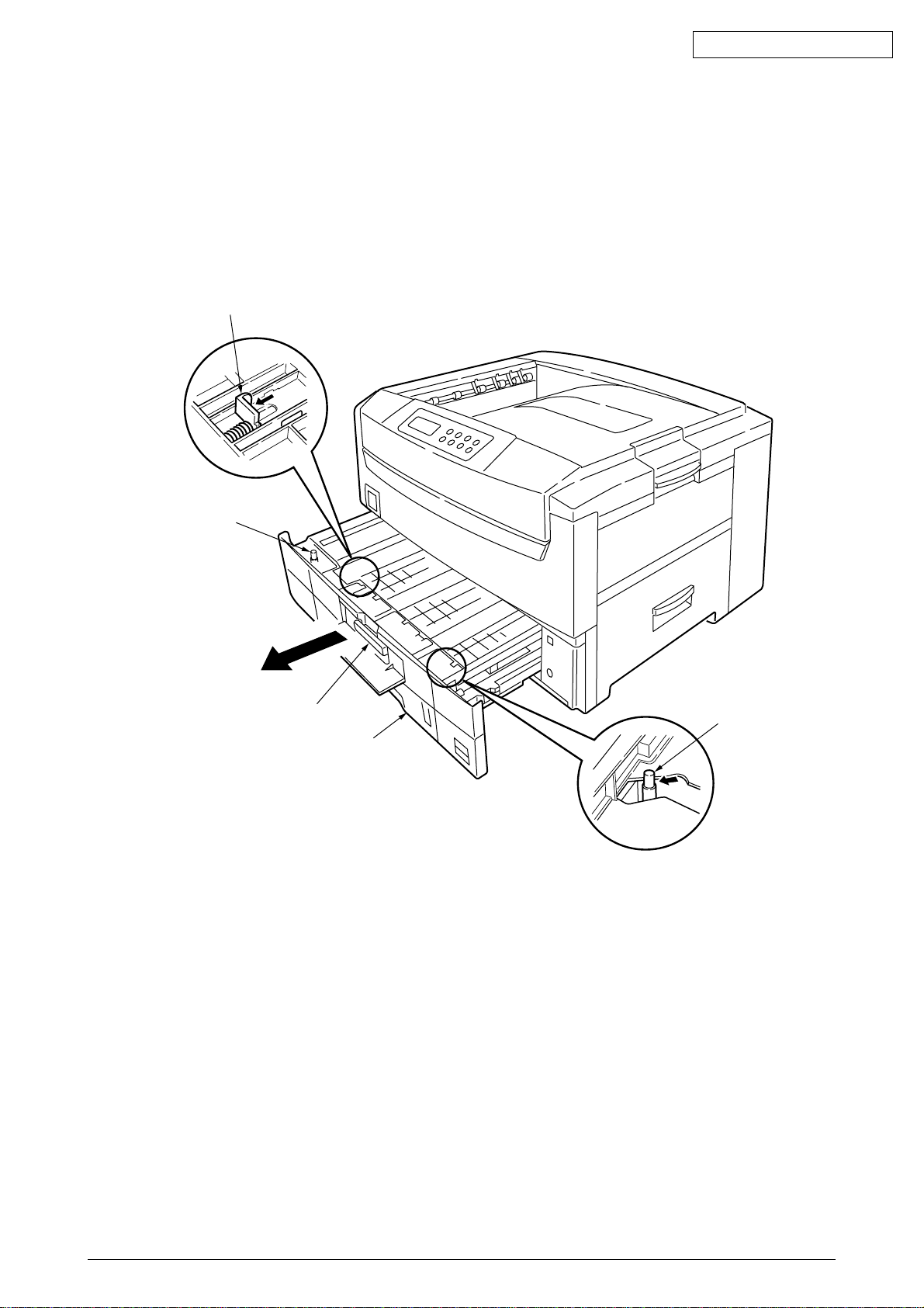
2.3.39 Duplex unit
(1) Remove the cassette Assy, the front cover and the front cover inner buffle.
(2) Unlatch the rear at the right and left and pull the duplex unit 1 toward the front.
4
Oki Data CONFIDENTIAL
5
2
3
1
41388601TH Rev.6 59 /
Page 60
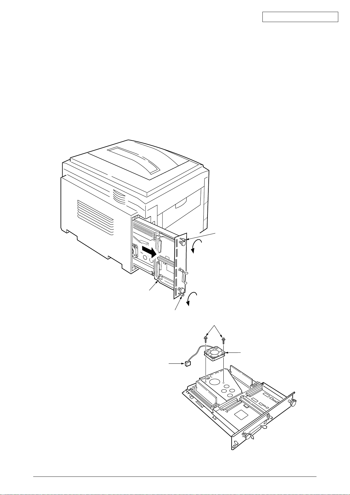
2.3.40 CU Assy
(1) Pulling out Control Board
1. Loosen the two screws 1.
2. Pull the control board 2 out.
3. Place the control board 2 on a flat table.
(2) Detaching Fan
1. Remove the connector 3.
2. Remove the two screws 4.
3. Detach the fan 5.
Oki Data CONFIDENTIAL
2
1
1
4
5
3
41388601TH Rev.6 60 /
Page 61
Oki Data CONFIDENTIAL
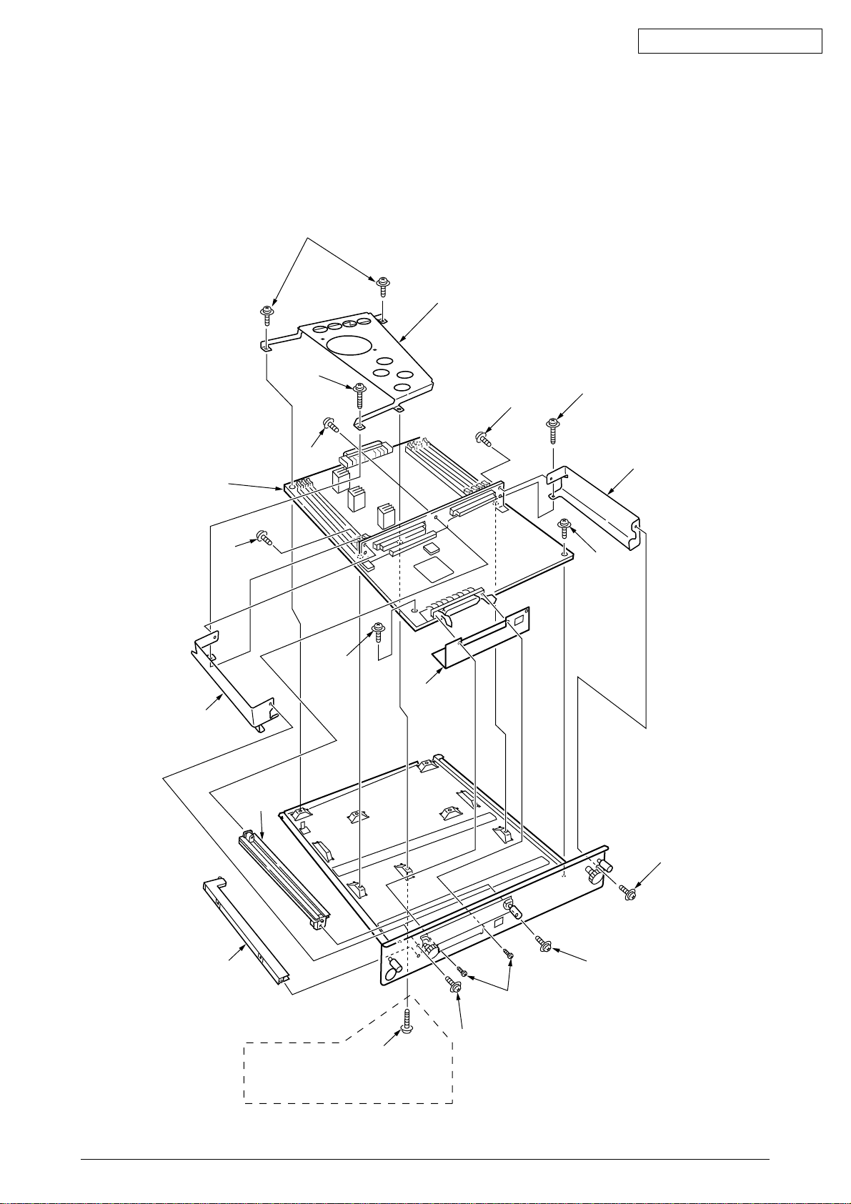
(3) Demounting SWA Board
1. Remove the three screws 6 and screw 7 to detach the fan bracket 8.
2. Remove the screw 9 and four screws 0 to detach the plate support A and the guide rail AB.
3. Remove the two screws C to detach the guide rail BD.
4. Remove the two screws E and two screws F and the plate -FG(Centro) G, then demount
the SWA board H.
6
8
7
9
0
A
H
0
D
C
A
F
F
G
0
B
C
E
0
41848502
(Board Assy .-cu[Maintenance])
Attached screw.
41388601TH Rev.6 61 /
6
Page 62
3. ADJUSTMENT
Adjustments are carried out by key operations on the operator panel.
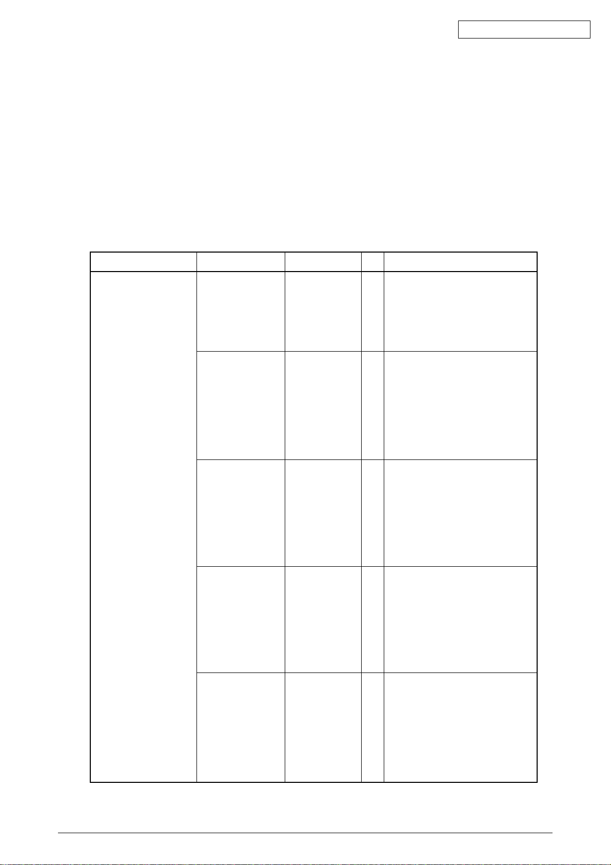
The maintenance menu is included in the general menu of this printer. Choose the maintenance
menu for adjustment.
3.1 Maintenance Menu and Its Functions
The general menu has the category, MAINTENANCE MENU.
The items adjustable in this menu are shown on the next page.
Maintenance Menu
Oki Data CONFIDENTIAL
Category
MAINTENANCE MENU
Item(1st Line)
Power Save Mode
Normal Paper Black
Setting
Normal Paper Color
Setting
Value(2nd Line)
Enabled
Disabled
0
+1
+2
-2
-1
0
+1
+2
-2
-1
DF
Sets the Power Save Mode
*
enabled/disabled. The shift time to
enable the Power Save mode can
be changed according to the
POWER SAVE SHIFT TIME item of
SYSTEM CONFIG MENU.
Implements fine adjustment of
*
BLACK printing on normal paper
when unclear characters or spots
are often found on print results.
With dispersed or snowed printing
in the part at high-density, decrease
the value. With unclear printing,
increase the value.
Implements fine adjustment of
*
COLOR printing on normal paper
when unclear characters or spots
are often found on the print result.
With dispersed or snowed printing
in the part at high-density, decrease
the value. With unclear printing,
increase the value.
Functions
Transparency Black
Setting
Transparency Color
Setting
41388601TH Rev.6 62 /
0
+1
+2
-2
-1
0
+1
+2
-2
-1
Implements fine adjustment of
*
BLACK printing on Transparency
when unclear characters or spots
are often found on the print result.
With dispersed or snowed printing
in the part at high-density, decrease
the value. With unclear printing,
increase the value.
Implements fine adjustment of
*
COLOR printing on Transparency
when unclear characters or spots
are often found on the print result.
With dispersed or snowed printing
in the part at high-density, decrease
the value. With unclear printing,
increase the value.
Page 63

3.2 Short Plug Settings
The SWA board has two short plugs that can be set as follows:
Short Plug (WE1)
Sets flash ROM DIMM to connect WE signals.
(1-2 Short: Disconnects WE signals; 2-3 Short: Connects WE signals.)
The factory-shipped short plug is set to the 2-3 short: Re-programmable the Flash ROM DIMM.
Short Plug (WE2)
(Not use)
3.3 Printing Singly Using Controller-Equipped Printer
Menu Map Printing
Prints the program versions, controller block, and other printer configuration and settings.
Operation: (Press of Switch)
Without HDD: “0” → “3” → “3”
With HDD: “0” → “0” → “3” → “3”
Oki Data CONFIDENTIAL
File List Printing
Prints a list of files stored on a HDD or in ROM.
Operation: (Press of Switch)
Without HDD: “0” → “3” → “1” → “3”
With HDD: “0” → “0” → “3” → “1” → “3”
Font List Printing (PCL)
Prints a list of PCL fonts.
Operation: (Press of Switch)
Without HDD: “0” → “3” → “1” → “1” → “3”
With HDD: “0” → “0” → “3” → “1” → “1” → “3”
Font List Printing (PS)
Prints a list of PS fonts.
Operation: (Press of Switch)
Without HDD: “0” → “3” → “1” → “1” → “1” → “3”
With HDD: “0” → “0” → “3” → “1” → “1” → “1” → “3”
Demo Printing
Prints the demo patterns for destinations.
Operation: (Press of Switch)
Without HDD: “0” → “3” → “1” → “1” → “1” → “1” → “3”
With HDD: “0” → “0” → “3” → “1” → “1” → “1” → “1” → “3”
Ethernet Board Self-Diagnostic Printing
When equipped with an Ethernet board, the printer runs diagnostic checks on itself by holding
the SW on the Ethernet board down for two seconds or more, and prints the results.
41388601TH Rev.6 63 /
Page 64

3.4 Adjustment after Part Replacement
Adjustment to be implemented after each part replacement is described below.
Adjustment and correction of color registration are always required for each part replacement.
Oki Data CONFIDENTIAL
Replaced Part
LED Head
Drum Cartridge (Y, M, C, K)
Fuser Unit
Belt Cassette Assy
PU (K73 Board)
*
Note:
When the EEPROM of the PU (K73 Board) is replaced to a new one, color balance must be
adjusted.
Adjustment
Color balance adjustment
Not required.
Not required.
Not required.
Re-mounting the EEPROM used prior to the replacement *Note
41388601TH Rev.6 64 /
Page 65

3.5 Color Balance Adjustment
Color balance has been adjusted appropriately when a printer is shipped from the plant. However,
it may be out of the appropriate balance during use. In such a case, color balance should be
modified.
Note:
Density of each color depends on each other. Therefore, adjustment must be repeated
several times to reach the correct color balance.
(1) Set A4 papers in the tray specified on the operator panel.
Oki Data CONFIDENTIAL
(2) Press
(3) Press
(4) Press
(5) Press
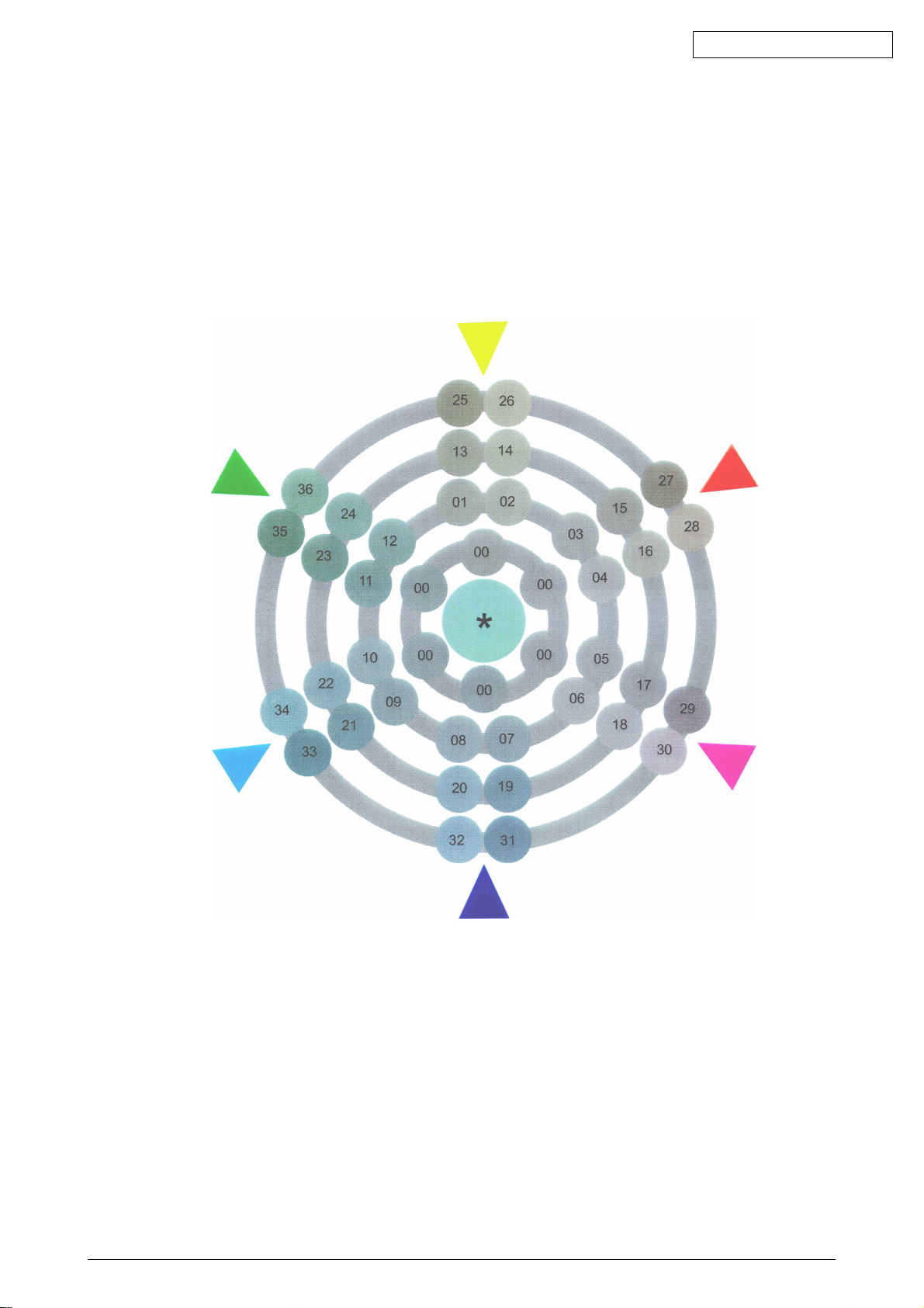
(6) Choose the number of the color closest to the [(] part on the test pattern.
(7) Press
(8) Press
(9) Repeat the steps (6)~(8) to approximate the color at the [(] part on the test pattern to [00]
(10)Press
))
) several times to display [COLOR MENU].
))
11
55
1 or
5 to display [COLOR BALANCE CORRECTION/PATTERN PRINT].
11
55
33
3 to start test printing.
33
11
1 to display [COLOR BALANCE CORRECTION/RESET].
11
If the selected color is [00], the color balance is correct and no adjustment is required.
If it is not [00], the color balance should be adjusted in the procedures below.
22
66
2 or
6 several times to display the value selected in Step (6).
22
66
33
3 to start test printing.
33
as much as possible.
44
4 to display [ON LINE].
44
41388601TH Rev.6 65 /
Page 66
Oki Data CONFIDENTIAL
41388601TH Rev.6 66 /
Page 67

Oki Data CONFIDENTIAL
3.6 EEPROM Replacement after SWA Board and K73 Board Replacement
When replacing the SWA Board or K73 Board, the EEPROM used by the user must be removed
and re-mounted on the new board (to deliver the user setting and font installment information to
the new board).
If the EEPROM used by the user is broken and not suitable for further use, the EEPROM on the
new board may be used.
41388601TH Rev.6 67 /
Page 68
4. REGULAR MAINTENANCE
4.1 Parts to be Replaced Regularly
It is recommended that a user should replace the parts below regularly according to the
replacement standard. (If not replaced, print quality is not assumed or it may result in a failure.)
Oki Data CONFIDENTIAL
Part Name
Large-capacity
Toner Cartridge
Toner Cartridge
ID Cartridge
Fuser Unit
Belt Unit
The above regular part replacement is performed by a user.
4.2 Cleaning
The inside and outside of this printer should be cleaned with wastes and hand cleaner, if necessary.
Note:
Do not touch the Image drum terminal, LED lens array and LED head connectors.
Time for Replacement
When the message “Toner Low”
is displayed.
When the message “Drum Life”
is displayed.
When the message “Fuser Life”
is displayed.
When the message “Belt Life” is
displayed.
Replacement Condition
After 15,000 copies have
been printed.
After 7,500 copies have
been printed.
After 26,000 copies have
been printed. (at 3P/J)
After 80,000 copies have
been printed.
After 80,000 copies have
been printed. (at 3P/J)
Adjustment after Replacement
Replace the Toner cartridge.
Reset the drum counter
after drum replacement.
Reset the fuser counter.
Reset the belt counter.
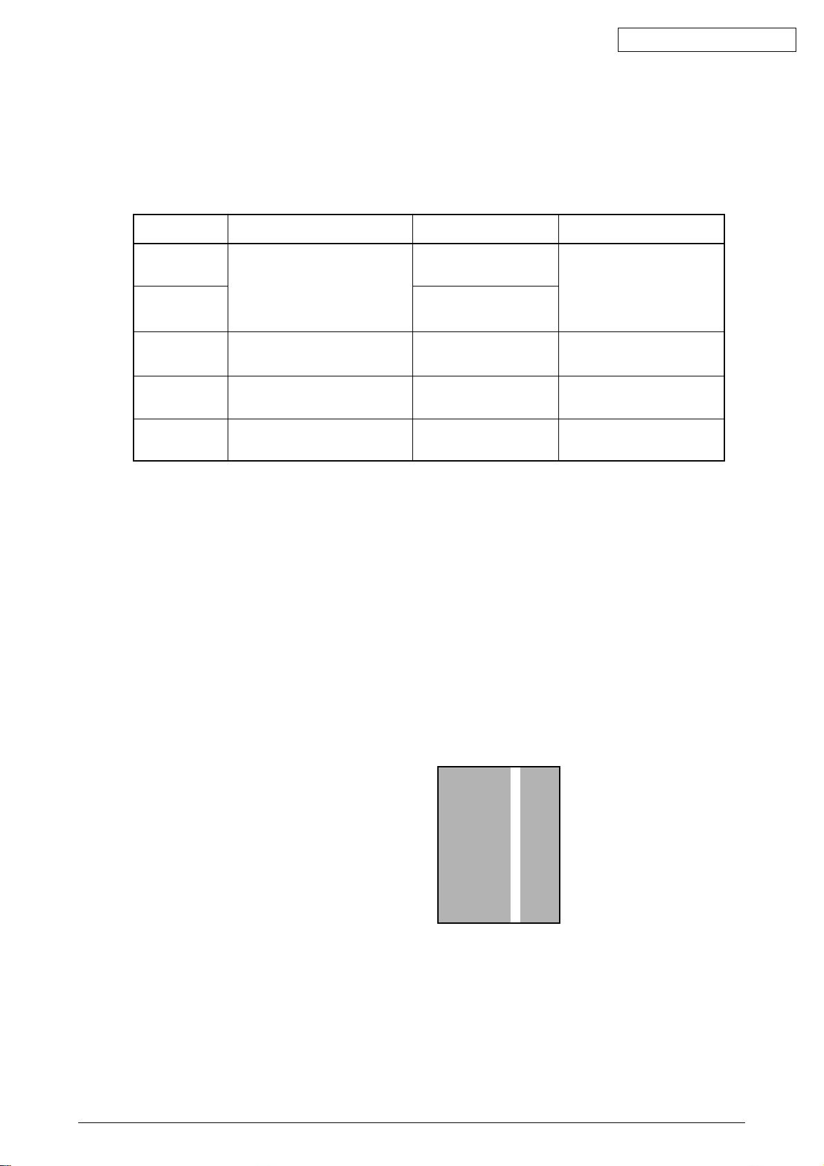
4.3 Cleaning of LED Lens Array
When a longitudinal white band or stripes (that is, void or light printing) appear on a printed paper
surface, the LED lens array should be cleaned.
Note:
The LED head cleaner must be used to clean the LED lens array. (The LED head cleaner
is included in the Toner cartridge box.)
White band, white stripes
(Void or light printing)
4.4 Cleaning of Pick-up Roller
When papers are not fed normally, the Pick-up roller should be cleaned.
Note:
Clean it with such as soft clothes and alcohol. Be cautious not to damage the roller surface.
41388601TH Rev.6 68 /
Page 69

5. TROUBLESHOOTING PROCEDURES
5.1 Tips for Troubleshooting
(1) Check the basic check points covered in the user’s manual.
(2) Gather as much information on the problem from the customer as possible.
(3) Perform inspections in conditions close to those in which the problem had occurred.
5.2 Check Points before Correcting Image Problems
(1) Is the printer being run in proper ambient conditions?
(2) Have the consumables toner and image drum cartridges been replaced properly?
(3) Is the paper normal? See paper specifications section.
Oki Data CONFIDENTIAL
(4) Has the image drum cartridge been loaded properly?
5.3 Tips for Correcting Image Problems
(1) Do not touch, or bring foreign matter into contact with the image drum surface.
(2) Do not expose the image drum to direct sunlight.
(3) Keep hands off the fuser unit as it is heated during operation.
(4) Do not expose the image drum to light for longer than 5 minutes at room temperature.
41388601TH Rev.6 69 /
Page 70
5.4 Preparation for Troubleshooting
(1) Operator panel display
The failure status of this printer is indicated on the LCD (liquid crystal display) of the Operator
panel.
Take the proper corrective action according to the message displayed on the LCD.
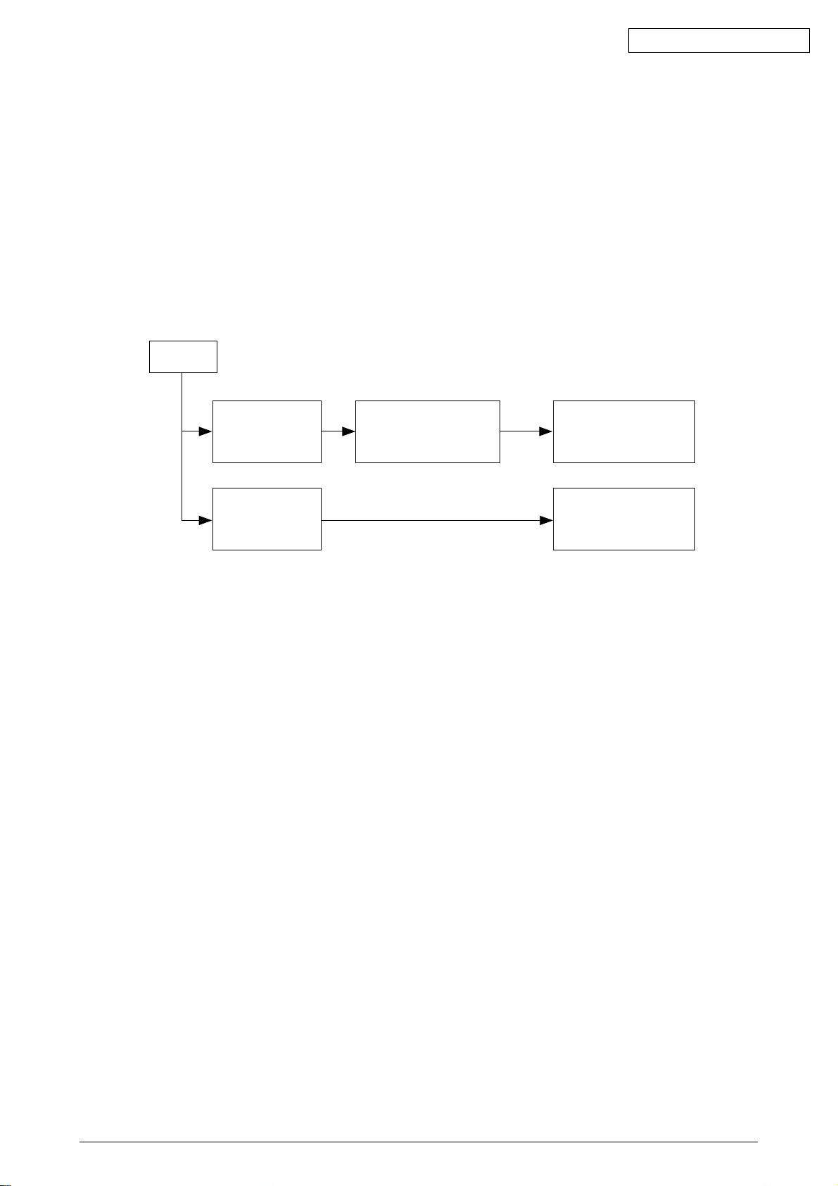
5.5 Troubleshooting Flow
If a problem should develop in this printer, troubleshoot in the following procedure.
Problem
Oki Data CONFIDENTIAL
Problem that results
in LCD message
indication
Image problem
(and a problem that
does not result in LCD
message indication.)
Troubleshoot based on the
LED message list.
See 5.5.1
Perform troubleshooting
with the troubleshooting
flow chart. See 5.5.2
Perform troubleshooting
with the troubleshooting
flow chart. See 5.5.3
41388601TH Rev.6 70 /
Page 71
5.5.1 LCD Message List
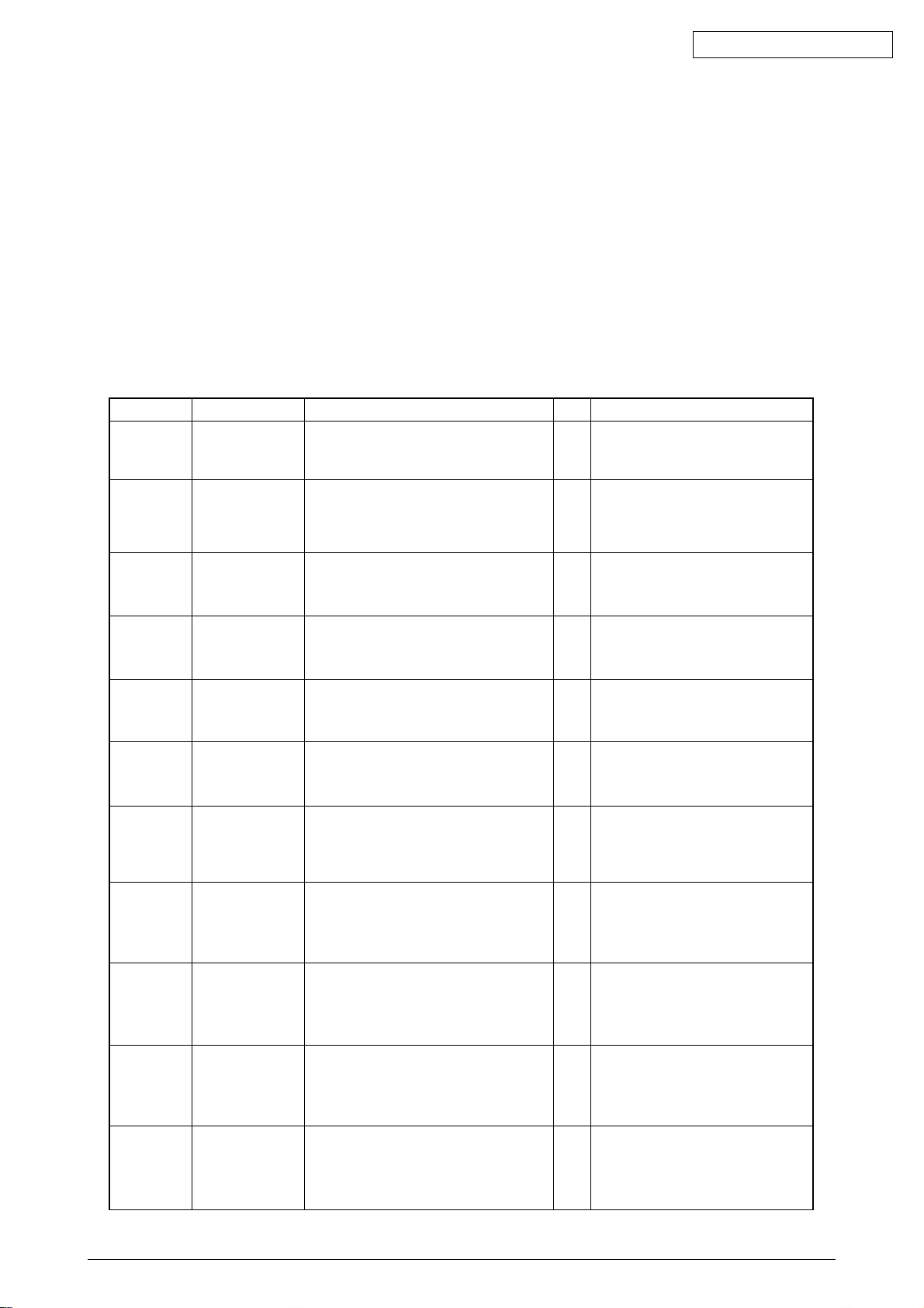
The printer indicates a Service Call Error message on the LCD as shown below, detecting an
unrecoverable error.
Service Call
nnn : Error
Note:
nnn is an error code.
When the Service Call message is displayed, the error information corresponding to the error code
appears on the lower line of the LCD. The meaning and solutions of each error code are listed in
the Table 5-1-1.
Table 5-1-1 Operator Alarms (1/6)
Message Cause Error Description Solutions
Service Call
001: Error
~
011: Error
Service Call
020: Error
Service Call
030: Error
Service Call
031: Error
Service Call
032: Error
Service Call
033: Error
Service Call
034: Error
Service Call
035: Error
Service Call
036: Error
Service Call
037: Error
Service Call
038: Error
CPU Exception
CU ROM Hash
Check Error 1
CU Slot1 DIMM
RAM Check Error
CU Slot2 DIMM
RAM Check Error
CU Slot3 DIMM
RAM Check Error
CU Slot4 DIMM
RAM Check Error
RAM Configuration
Error.
The CU RAM
installation or
derwas not followed.
Slot1 RAM Spec Error.
The CU RAM Slot1
DIMM specification
is not supported.
Slot2 RAM Spec Error.
The CU RAM Slot2
DIMM specification
is not supported.
Slot3 RAM Spec Error.
The CU RAM Slot3
DIMM specification
is notsupported.
Slot4 RAM Spec Error.
The CU RAM Slot4
DIMM specification
is notsupported.
Is the error message displayed again?
Is the error message displayed again?
Is the program ROM DIMM installed
properly?
Can the printer recover from the error by
replacing the program ROM DIMM?
Is the concerned RAM DIMM installed
properly?
Can the printer recover from the error by
replacing the RAM DIMM?
Is the concerned RAM DIMM installed
properly?
Can the printer recover from the error by
replacing the RAM DIMM?
Is the concerned RAM DIMM installed
properly?
Can the printer recover from the error by
replacing the RAM DIMM?
Is the concerned RAM DIMM installed
properly?
Can the printer recover from the error by
replacing the RAM DIMM?
Is the installation order followed?
Can the printer recover from the error by
replacing the RAM DIMMs?
Is the RAM DIMM a genuine part?
Is the concerned RAM DIMM installed
properly?
Can the printer recover from the error by
replacing the RAM DIMM?
Is the RAM DIMM a genuine part?
Is the concerned RAM DIMM installed
properly?
Can the printer recover from the error by
replacing the RAM DIMM?
Is the RAM DIMM a genuine part?
Is the concerned RAM DIMM installed
properly?
Can the printer recover from the error by
replacing the RAM DIMM?
Is the RAM DIMM a genuine part?
Is the concerned RAM DIMM installed
properly?
Can the printer recover from the error by
replacing the RAM DIMM?
Yes
Turn the printer off/on.
Replace the SWA board.
Yes
(The EEPROM needs replacement.)
No
Re-install the program ROM DIMM.
Yes
Replace the program ROM DIMM.
Replace the SWA board.
No
(The EEPROM needs replacement.)
Re-install the concerned RAM DIMM.
No
Replace the RAM DIMM.
Yes
Replace the SWA board.
No
(The EEPROM needs replacement.)
No
Re-install the concerned RAM DIMM.
Yes
Replace the RAM DIMM.
No
Replace the SWA board.
(The EEPROM needs replacement.)
No
Re-install the concerned RAM DIMM.
Yes
Replace the RAM DIMM.
No
Replace the SWA board.
(The EEPROM needs replacement.)
Re-install the concerned RAM DIMM.
No
Replace the RAM DIMM.
Yes
Replace the SWA board.
No
(The EEPROM needs replacement.)
No
Correct the installation order.
Yes
Replace the RAM DIMMs.
No
Replace the SWA board.
(The EEPROM needs replacement.)
Use a genuine RAM DIMM.
No
Re-install the concerned RAM DIMM.
No
Replace the RAM DIMM.
Yes
Replace the SWA board.
No
(The EEPROM needs replacement.)
Use a genuine RAM DIMM.
No
No
Re-install the concerned RAM DIMM.
Replace the RAM DIMM.
Yes
Replace the SWA board.
No
(The EEPROM needs replacement.)
Use a genuine RAM DIMM.
No
No
Re-install the concerned RAM DIMM.
Replace the RAM DIMM.
Yes
Replace the SWA board.
No
(The EEPROM needs replacement.)
Use a genuine RAM DIMM.
No
No
Re-install the concerned RAM DIMM.
Replace the RAM DIMM.
Yes
Replace the SWA board.
No
(The EEPROM needs replacement.)
Oki Data CONFIDENTIAL
41388601TH Rev.6 71 /
Page 72
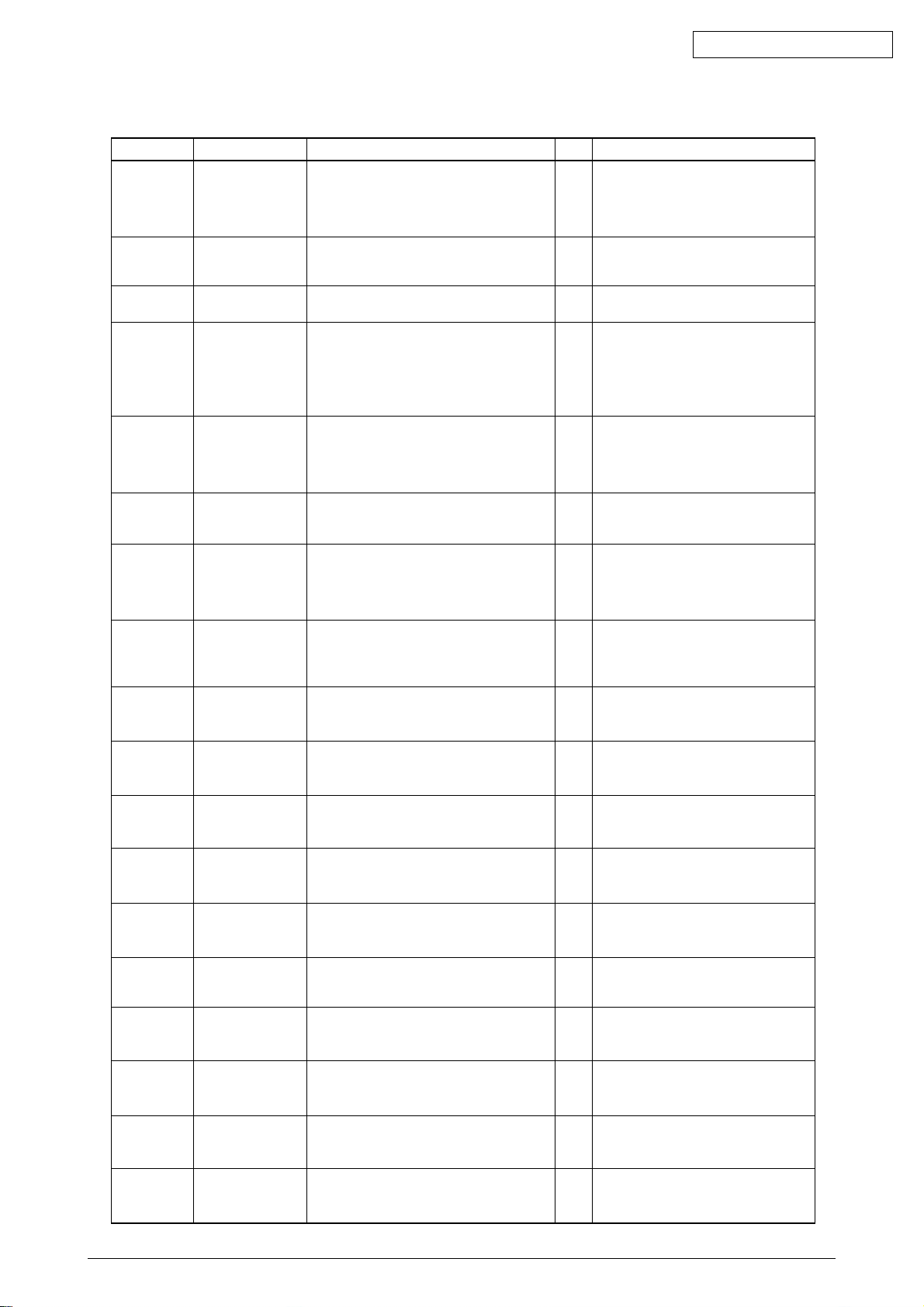
Table 5-1-1 Operator Alarms (2/6)
Message Cause Error Description Solutions
Service Call
040: Error
Service Call
041: Error
Service Call
050: Error
Service Call
051: Error
Service Call
063: Error
Service Call
070: Error
Service Call
072: Error
Service Call
073: Error
~
075: Error
Service Call
090:Error
Service Call
091: Error
Service Call
092: Error
Service Call
093: Error
Service Call
094: Error
Service Call
100/100:Error
Service Call
102: Error
Service Call
103: Error
Service Call
104: Error
Service Call
105: Error
CU EEPROM Error
U Flash Error.
On-CU-board Flash
ROM Error
Operator Panel Error
CU Fan Error.
On-CU-board CPU
Cooling Fan
Problem
Network Comm.Error.
CU ~ NIC H/W I/F
Problem
CANT_HAPPEN.
PS F/W Problem
Detection
Engine Communication
Error
PU ~ CU I/F Error
Video Overrun
Detect
Error detected at
Staple-Motor in the
Finisher.
Error detected at
Tray-Elevator-Motor in
the Finisher.
Error detected at
Ignition-Belt-Motor of
bin#2 in the Finisher.
Error detected at
Jogging-Motor in the
Finisher.
Error detected at
Main-Feed-Motor in the
Finisher.
Error detected at Engine
ROM Checksum when
turned on.
Error detected at Engine
RAM Read/Write when
turned on.
Error detected at Engine
SRAM Read/Write when
turned on.
Error detected at Engine
EEPROM Checksum
when turned on.
EEPROM not detected
when turned on.
Can the printer recover from the error by
replacing the EEPROM on the CU board?
Does the error message appear again? Yes Replace the SWA board.
Does the error message appear again? Ye s See the flowchart for the problems with
Is the on-CU-board connector connected
properly?
Can the printer recover from the error by
replacing the fan?
Is the network board installed properly?
Can the printer recover from the error by
replacing the network board?
Is it recovered by turning the printer off/on. No Replace the SWA board.
Is the CU Assy installed properly?
Can the printer recover from the error by
replacing the SWA board?
Is the CU Assy installed properly?
Can the printer recover from the error by
replacing the SWA board?
1) Is the error message displayed? Ye s
2) Does the error repeat?
1) Is the error message displayed? Ye s Turn off/on the printer.
2) Does the error repeat?
1) Is the error message displayed?
2) Does the error repeat?
1) Is the error message displayed?
2) Does the error repeat?
1) Is the error message displayed?
2) Does the error repeat?
Does the error repeat? No
Does the error repeat? Yes Replace the engine control board (K73).
Does the error repeat? Yes Replace the engine control board (K73).
Does the error repeat? Yes Replace the engine control board (K73).
No EEPROM?
Does the error repeat?
YesNoReplace the EEPROM. (Settings of the
user must be restored on the new.)
Replace the SWA board.
(The EEPROM needs replacement.)
(The EEPROM needs replacement.)
no LCD message displayed.
No
Connect the connector properly.
Yes
Replace the fan.
No
Replace the SWA board.
(The EEPROM needs replacement.)
Install the network board properly.
No
Replace the network board.
Yes
Replace the SWA board.
No
(The EEPROM needs replacement.)
(The EEPROM needs replacement.)
No
Install the CU Assy properly.
Yes
Replace the SWA board.
(The EEPROM needs replacement.)
No
Replace the PU board.
No
Install the CU Assy properly.
Yes
Replace the SWA board.
(The EEPROM needs replacement.)
Turn off/on the printer.
Yes
Replace the Stapler-Motor in the
Finisher.
Ye s Replace the
Finisher.
Yes Turn off/on the printer.
Ye s Replace the
the Finisher.
Yes Turn off/on the printer.
Ye s Replace the
Finisher.
Yes Turn off/on the printer.
Ye s Replace the
Finisher.
Replace the PU board.
Yes
Replace the engine control board (K73).
Yes
Confirm the existence of EEPROM.
Without it, mount an EEPROM.
Replace the engine control board (K73).
Yes
Tray-Elevator-
Ignition-Belt-Motor of bin#2
Jogging-Motor
Main-Feed-Motor
Oki Data CONFIDENTIAL
Motor in the
in
in the
in the
41388601TH Rev.6 72 /
Page 73
Oki Data CONFIDENTIAL
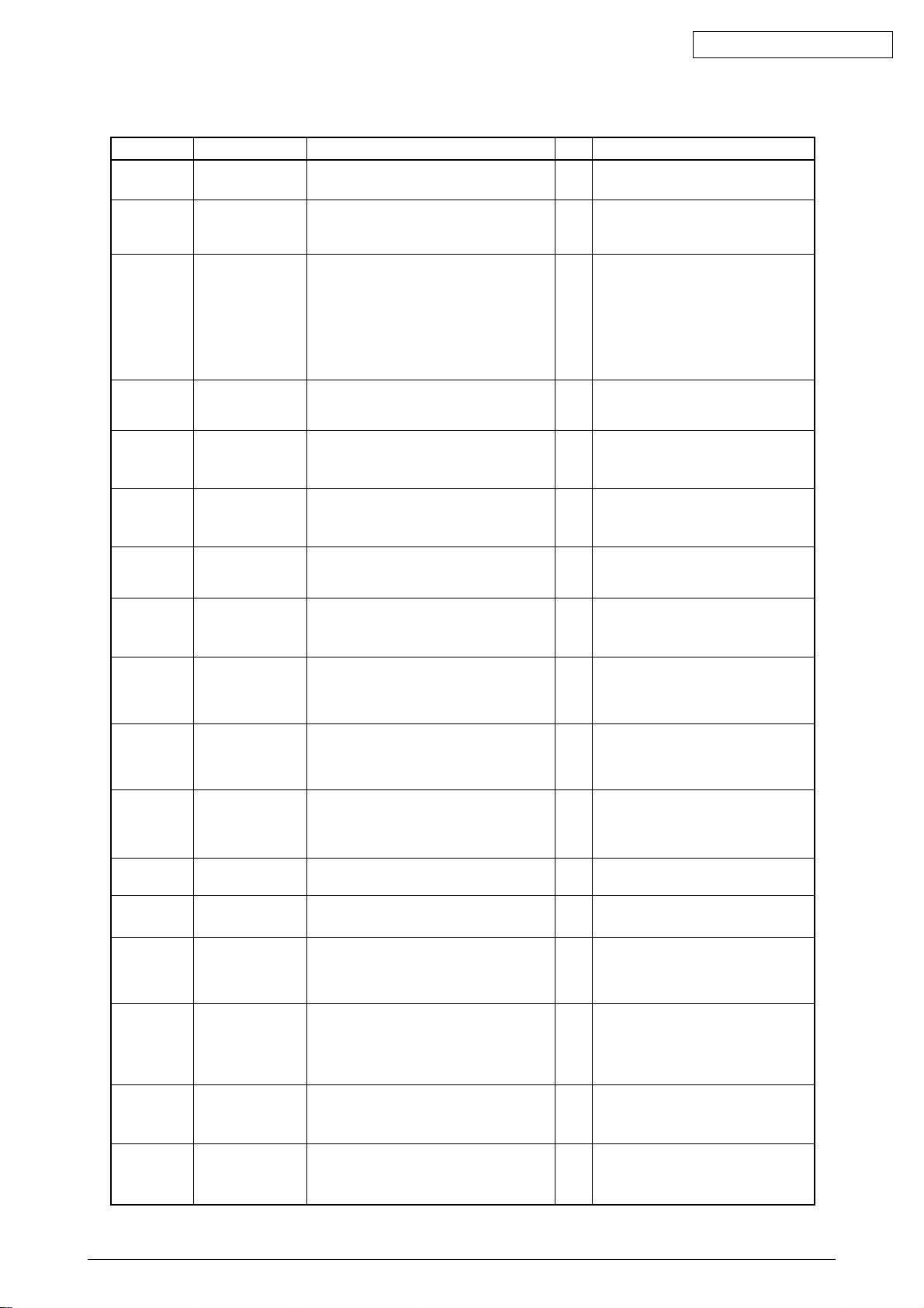
Table 5-1-1 Operator Alarms (3/6)
Message Cause Error Description Solutions
Service Call
106: Error
Service Call
120: Error
Service Call
121: Error
Service Call
122: Error
Service Call
123: Error
Service Call
124: Error
Service Call
125: Error
Service Call
130: Error
Service Call
131: Error
~
134: Error
Service Call
140: Error
~
142: Error
Service Call
150: Error
~
153: Error
Service Call
154: Error
Service Call
155: Error
Service Call
160: Error
~
163: Error
Service Call
170: Error
171: Error
174: Error
175: Error
Service Call
172: Error
176: Error
Service Call
173: Error
177: Error
Error detected at Engine
Control Logic.
Error detected at cooling
fan for Engine PCB
(PCB-K73).
Error detected at two
Power Unit cooling fans.
/Error detected at
Power Unit temperature
rise. /Error detected at
Charge output or
Interface signals in Highvoltage Power Unit.
Error detected at fan for
a heater exhaust gas.
Inappropriate ambient
RH detected by a
sensor.
Inappropriate ambient
temp. detected by a
sensor.
Error detected at the
MT home position.
Temperature rise at
the LED head
detected.
No LED head unit
detected when
turning on the printer
or closing the cover.
Error detected with
the D located at
appropriate position.
Fuse in the ID unit
has not been blown.
Fuse in the Belt unit
has not been blown.
Fuse in the Fuser unit
has not been blown.
Error detected by
Toner sensor.
Short or open circuit
detected at the Fusert
hermistor. (H or L
temperature error)
High temperature
error detected at
Thermistor.
Low temperature
error detected at
Thermistor.
Does the error repeat? Yes
1) Is the error message displayed?
2) Does the error repeat?
1) Is the error message displayed?
2) Does the error repeat?
1) Is the error message displayed?
2) Does the error repeat?
1) Is the error message displayed?
2) Does the error repeat?
1) Is the error message displayed?
2) Does the error repeat?
1) Is the error message displayed?
2) Does the error repeat?
1) Is the error message displayed?
2) Does the error repeat?
1) Is the error message displayed?
2) Is the LED head mounted properly?
3) Does the error repeat?
1) Is the error message displayed?
2) Does the error repeat?
Is the ID unit mounted properly? Yes Confirm the cable connection, or
Is the Belt unit mounted properly?
Is the Fuser unit mounted properly? Yes Confirm the cable connection, or
1) Is the error message displayed?
2) Does the error repeat?
1) Is the error message displayed?
2) Does the error repeat?
1) Is the error message displayed?
2) Does the error repeat?
1) Is the error message displayed?
2) Does the error repeat?
Replace the engine control board (K73).
Turn off/on the printer.
Yes
Yes
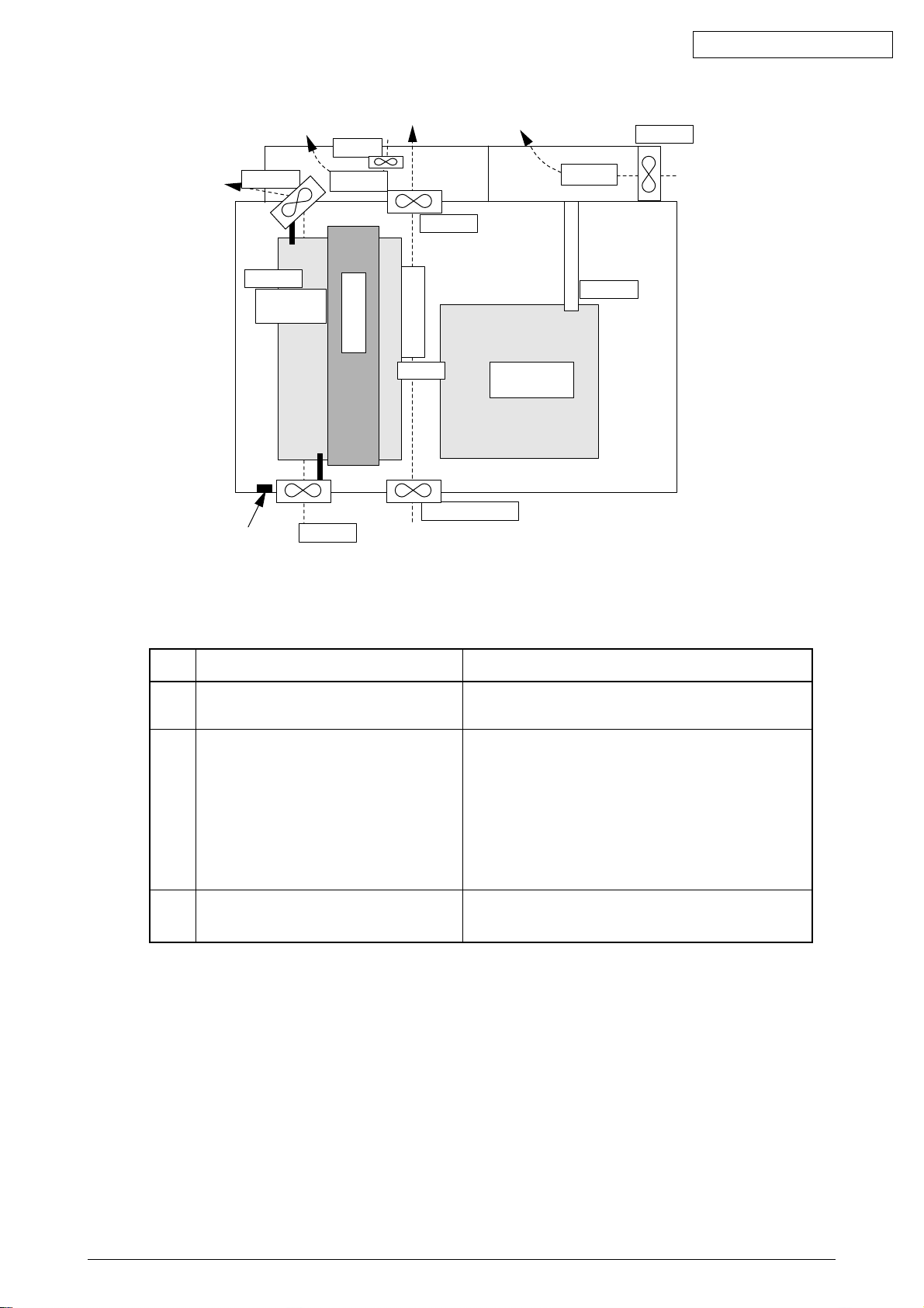
Refer fig.5.5.1 A power supply-related
error.
Turn off/on the printer.
Yes
Yes
Refer fig.5.5.1 A power supply-related
error.
Turn off/on the printer.
Yes
Yes
Refer fig.5.5.1 A power supply-related
error.
Yes
Turn off/on the printer.
Yes
Replace the RH sensor.
Turn off/on the printer.
Yes
Yes
Replace the temperature sensor.
Yes
Turn off/on the printer.
Yes
Replace the MT.
Yes
Turn off the printer, leave it for 30 min and
then turn it on again.
Yes
Replace the LED head unit.
Yes
Verify the installation of the LED head.
Yes
Turn off/on the printer.
Yes
Replace the LED head Assy.
Yes
Turn off/on the printer.
Yes
Replace the Drum Assy.
replace the Engine board.
Yes
Confirm the cable connection, or
replace the Engine board.
replace the Engine board.
Yes
Replace Toner sensor or Assy
(Y71-PWB).
Yes
Same as the above.
Yes
Turn off/on the printer.
Yes
Replace the Thermistor and turn off the
printer. Leave it for 30 min.
Yes
Turn off/on the printer.
Yes
Replace the Thermistor and turn off the
printer. Leave it for 30 min.
Yes
Turn off/on the printer.
Yes
Replace the Thermistor or heater and
turn off the printer.
41388601TH Rev.6 73 /
Page 74
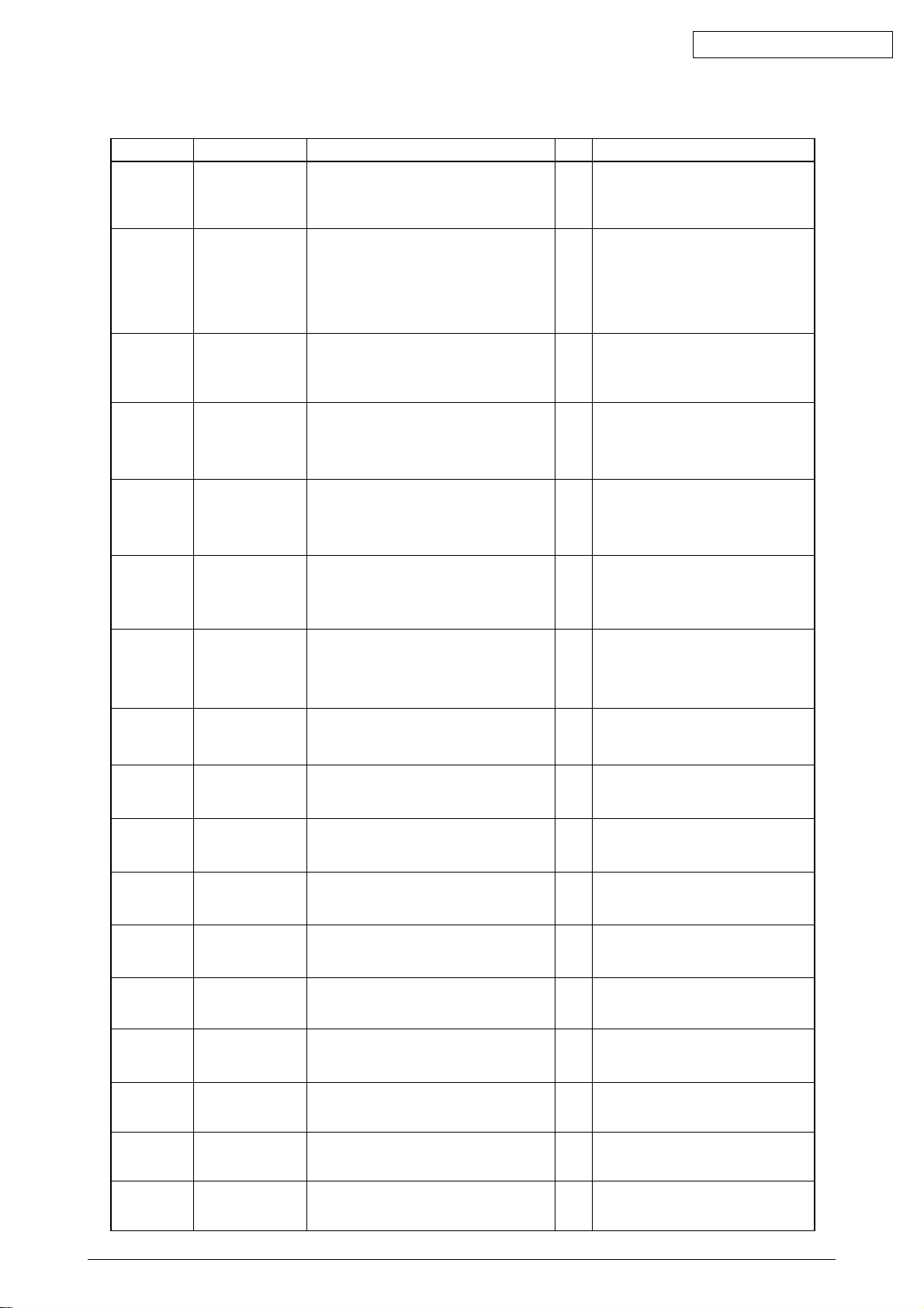
Table 5-1-1 Operator Alarms (4/6)
Message Cause Error Description Solutions
Service Call
181: Error
~
185: Error
Service Call
186: Error
Close Cover
310: CCCC
CoverOpen
(* = A4, B4 etc.)
Check Fuser
320:
Fuser Error
Check Belt
330:
Belt Error
Check Drum
340~343:
Drum Error
Install New Drum
350: Y Drum Life
351: M Drum Life
352: C Drum Life
353: K Drum Life
Install Duplex Unit
360: No Duplex
unit
Remove Finisher
361: Paper Jam
Remove Finisher
362: Paper Jam
Remove Finisher
363: Paper Jam
Remove Finisher
364: Paper Jam
Remove Finisher
365: Paper Jam
Remove Finisher
366: Paper Jam
Remove Finisher
367: Paper Jam
Check DUPLEX
370: Paper Jam
Communication
failure with an option
unit detected by
Engine
Error detected at
Interface to the
Finisher-Unit.
Printer engine cover
is open.
No Fuser unit detected
when turning on the
printer or closing the
cover.
No Belt unit detected
when turning on the
printer or closing the
cover.
No ID unit detected
when turning on the
printer or closing the
cover.
End of the ID unit life.
26,000 or more
copies printed.
The Duplex unit is
removed from the
printer.
Paper jam detected
at befor input area.
Paper jam detected
at input area.
Paper jam detected
at regist roller.
Paper jam detected
at invert path.
Paper jam detected
at invert stack.
Paper jam detected
at Bin#1 exit.
Paper jam detected
at Bin#2 exit.
Paper jam detected
after paper reverse in
the Duplex unit.
1) Is the error message displayed?
2) Does the error repeat?
1) Is the error message displayed?
2) Does Interface cable to the finisher
connect properly?
3) Does AC cable to the finisher connect
properly?
4) Does the error repeat?
1) Is the Top cover open?
2) Does the Cover switch operatenormally?
1) Is the error message displayed?
2) Is the Fuser unit mounted properly?
3) Does the error repeat?
1) Is the error message displayed?
2) Is the Belt unit mounted properly?
3) Does the error repeat?
1) Is the error message displayed?
2) Is the ID unit mounted properly?
3) Does the error repeat?
Is it displayed soon after the ID unit
replacement?
Recovered if the Duplex unit is inserted
again?
Is a paper jammed at befor input area? YesNoRemove the jammed paper.(See Fig.
Is a paper jammed at input area? YesNoRemove the jammed paper.(See Fig.
Is a paper jammed at regist roller? YesNoRemove the jammed paper.(See Fig.
Is a paper jammed at invert path? YesNoRemove the jammed paper.(See Fig.
Is a paper jammed at invert stack? YesNoRemove the jammed paper.(See Fig.
Is a paper jammed at Bin#1 exit? YesNoRemove the jammed paper.(See Fig.
Is a paper jammed at Bin#2 exit? YesNoRemove the jammed paper.(See Fig.
1) Is a paper jammed in the Duplex unit? YesNoRemove the jammed paper.
Yes
Turn off/on the printer.
Yes
Replace the option unit.
Yes
Turn off/on the printer.
Yes Re-connect Interface cable finisher and
turn off/on the printer.
Yes Re-connect AC cable finisher and turn
off/on the printer.
Yes
Replace the Interface cable or AC cable.
Close the Top cover.
Yes
Close the Side cover.
Yes
Replace the Cover switch.
No
Confirm the existence of the unit.
Yes
Re-install the Fuser unit and turn off/on
No
the printer.
Replace the Fuser unit Assy.
Yes
Yes
Confirm the existence of the unit.
Re-install the Belt unit and turn off/on
No
the printer.
Replace the Belt unit Assy.
Yes
Confirm the existence of the unit.
Yes
Re-install the ID unit and turn off/on the
No
printer.
Replace the ID unit Assy.
Yes
YesNoConfirm the life of the ID unit.
Replace the ID unit.
YesNoNormal
Replace the Duplex unit or Engine board.
5.5.2 No.361)
Replace the Finisher unit.
5.5.2 No.362)
Replace the Finisher unit.
5.5.2 No.363)
Replace the Finisher unit.
5.5.2 No.364)
Replace the Finisher unit.
5.5.2 No.365)
Replace the Finisher unit.
5.5.2 No.366)
Replace the Finisher unit.
5.5.2 No.367)
Replace the Finisher unit.
Check the Duplex unit, or replace it.
Oki Data CONFIDENTIAL
Check DUPLEX
371: Paper Jam
Paper jam detected
at the Duplex unit
1) Is a paper jammed in the Duplex unit? YesNoRemove the jammed paper.
Check the Duplex unit, or replace it.
41388601TH Rev.6 74 /
Page 75
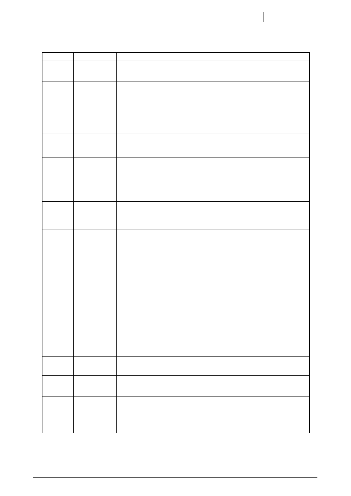
Table 5-1-1 Operator Alarms (5/6)
Message Cause Error Description Solutions
Check DUPLEX
372: Paper Jam
Open Side Cover
380: Paper Jam
Open Stacker
Cover
381: Paper Jam
Open Stacker
Cover
382: Paper Jam
Open Stacker
Cover
383: Paper Jam
Check MP Tray
390: Paper Jam
Check Tray *
391~395: Paper
Jam
Open Stacker
Cover
400: Paper Size
Error
Toner Low
410: Yellow
411: Magenta
412: Cyan
413: Black
Check Stapler
Cartridge
471: Stapler
Cartridge
Missing
Check Punch
Chip Box
472: Punch
Chip Box
Missing
Install Finisher
473: Finisher is
Removed
Remove Printed
Papers
480: Stacker Full
Load *** Papers
490: No paper in
the MP Tray
(*** = A4, B5 etc.)
Paper jam detectedd
uring paper feed
from the Duplex unit.
Paper jam during
paper feed from the
Cassette 1, 2, 3, 4 or 5.
Paper jam detected
btwn the B ID and
Fuser.
Paper jam detected in
the Fuser unit or btwn
the Fuser and paper
ejection.
Paper jam detected
on paper entering
the Duplex unit.
Paper jam during
paper feed from the
MP Tray.
Paper jam detected
btwn a cassette and
the B ID.
Paper in a size different
(45 mm or more) from
the specification
detected at the Printer
engine.
Toner in one of the
four colors is running
short.
Stapler cartridge is not
mounted in the
Finisher.
Punch chip box is not
mounted in the
Finisher.
The Finisher is
separated.
The stacker for ejected
papers is full.
The specified cassette
has no paper or is
removed. Or, the
cassette be ingused for
printing has no more
paper.
1) Does misfeed occur in the Duplex unit? YesNoRemove the misfed paper and close
1) Does misfeed occur in the specified
cassette?
1) Is a paper jammed between the Y ID and
Fuser?
2) Is the load on the Fuser unit normal?
1) Is a paper jammed in the Fuser unit or
between the Y ID and Fuser unit?
2) Is the Paper eject switch work normally?
1) Is a paper jammed at the entrance of the
Duplex unit or in the unit?
1) Does misfeed occur around the MP Tray? YesNoRemove the misfed paper and close the
1) Is a paper jammed around the cassette
or between the B ID and cassette.
2) Does the Paper entry switch operate
normal?
1) Is the paper in a custom size?
2) Is the paper in the standard size?
1) Is the specified toner cartridge almost
empty?
2) Does the Toner sensor of the specified
cartridge operate normally?
1) Is the message displayed?
2) Does the error repeated?
1) Is the message displayed?
2) Does the error repeated?
1) Is the message displayed?
2) Does the error repeated?
1) Is the stacker full?
2) Does the Stacker full sensor operate
normally?
1) No paper in MT?
2) Does the Paper out sensor operate
normally?
the cover.
Check the Duplex unit, or replace it.
YesNoRemove the jammed paper and install
the cassette.
Check the Cassette 1, 2, 3, 4 or 5, or
replace it.
YesNoRemove the jammed paper.
Replace the Fuser unit.
YesNoRemove the jammed paper.
Replace the Fuser unit.
YesNoRemove the jammed paper and close.
Check the Duplex unit, or replace it.
cover.
Check the MP Tray, or replace it.
YesNoRemove the jammed paper.
Replace the Paper entry switch.
Yes
No action required.
Yes
Adjust the Paper size guide of the
cassette.
Replace the Paper size board
No
(B73 PWB).
YesNoReplace it with a new toner kit.
Replace the Toner sensor for the
specified color.
Yes
Turn off/on the printer.
Yes
Mount the Stapler Cartridge.
Yes
Turn off/on the printer.
Yes
Mount the Punch Chip Box.
Yes
Turn off/on the printer.
Yes
Install the Finisher.
YesNoRemove papers from the stacker.
Replace the Stacker full sensor.
YesNoLoad papers in MT.
Replace the Paper out sensor.
Oki Data CONFIDENTIAL
41388601TH Rev.6 75 /
Page 76
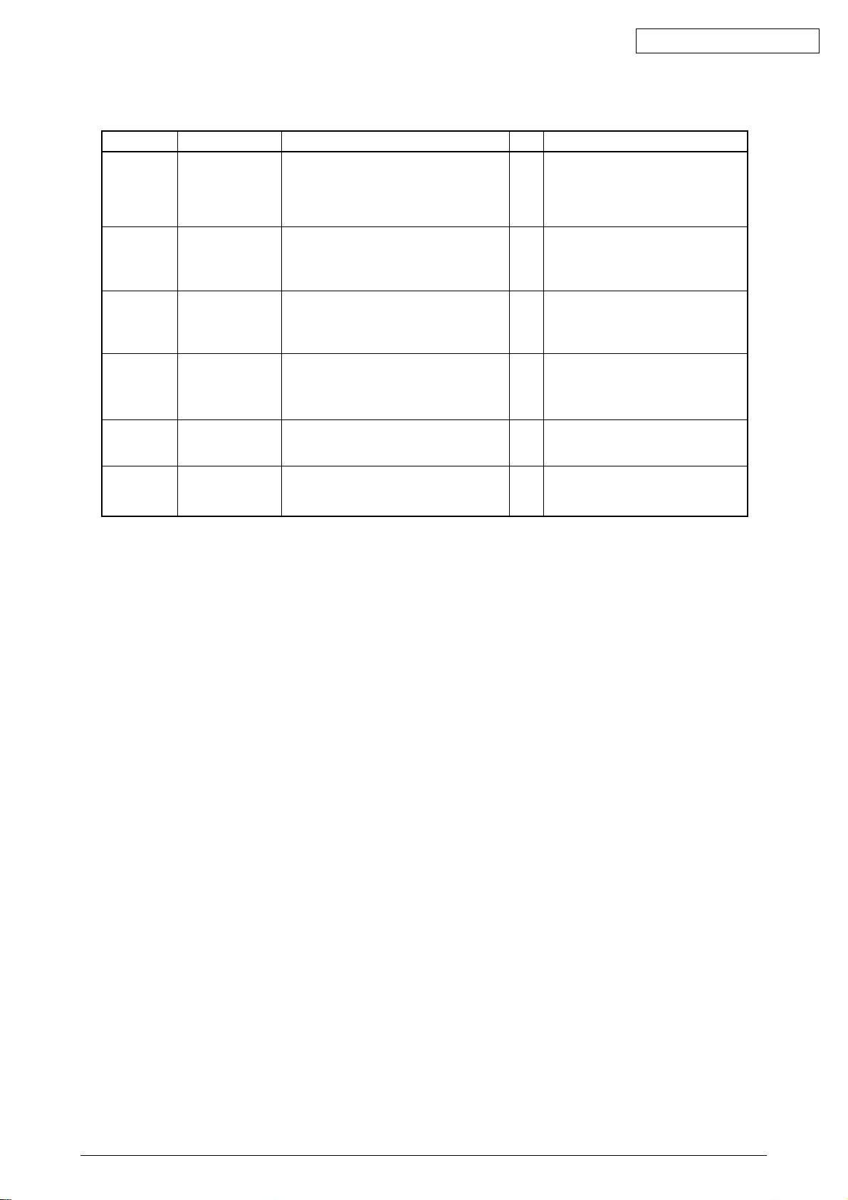
Table 5-1-1 Operator Alarms (6/6)
Message Cause Error Description Solutions
Load *** Papers
491~495: No
paper in the Tray
*
(*** = A4, B5 etc.)
Replace Belt The belt counter has
Replace Fuser The fuser counter has
No paper in the
Cassette 1, 2, 3, 4 or 5
detected.
reached the life value.
reached the lifevalue
1) No paper in the specified cassette?
2) Does the Paper out sensor operate
normally?
1) Is the error message displayed?
2) Does the error occur soon after Belt unit
replacement?
1) Is the error message displayed?
2) Does the error occur soon after
Fuser unit replacement?
YesNoLoad papers in the specified cassette.
Replace the Paper out sensor of the
specified cassette.
YesNoCheck the belt life.
Replace the Belt unit immediately or at
the next maintenance.
YesNoCheck the fuser life.
Replace the Fuser unit immediately or
at the next maintenance.
Oki Data CONFIDENTIAL
Job Offset Home
Error
Running Short of
Paper in Tray *
Disc Operation
Error
The Job offset assy
does not operate or
cannot detect the
home position.
Running short of paper
detected
HDD cannot be written.
Does the Job offset assy operate normally? YesNoReplace the Job offset sensor.
Does only small mount of papers
(approx. 30 sheets or less) remain?
Is the operating procedure correct? No
Replace the Job offset motor or Engine
board.
YesNoLoad papers.
Check the Paper near end sensor.
Confirm the procedure in the manual.
Yes
Replace the HDD as it is broken.
41388601TH Rev.6 76 /
Page 77
Oki Data CONFIDENTIAL
Equipment plane view
S/C-121
FAN#2
S/C-121
Power
Supply Unit
FAN#1
AC SW
S/C-121
FAN#5
S/C-51
CUboaud
Heater
FAN#3
S/C-122
Heater exhaust
S/C-unspecified
S/C-120
PU
FAN#4
S/C-121
High-voltage
Power Supply
Notice: S/C---> Service Call
Figure 5.5.1 A Power Supply-related Error
S/C
120
Error detected at cooling fan for Engine
PCB(PCB-K73 PU board).
121
Error detected at two Power Unit cooling
fans./ Error detected at Power Unit
temperature rise./ Error detected at
charge output or Interface signals in
High-voltage Power Unit.
Error detected at fan for a heater exhaust
122
gas.
Description
Action
Change FAN#4.
Change FAN#1 or / and FAN#2 when a error occurs
and the FAN#1 or FAN#2 are not turnning. In this case,
please also check contents of 5.5.2 LCD message
troubleshooting-6Fan motor error. If Both FAN#1 and
FAN#2 are turnning, change a Belt-Unit. If an error
occurs also with this means, change a High-Voltage
Power Supply Unit. If an error occurs also with this
means, change a Power Supply Unit.
Change FAN#3.
41388601TH Rev.6 77 /
Page 78
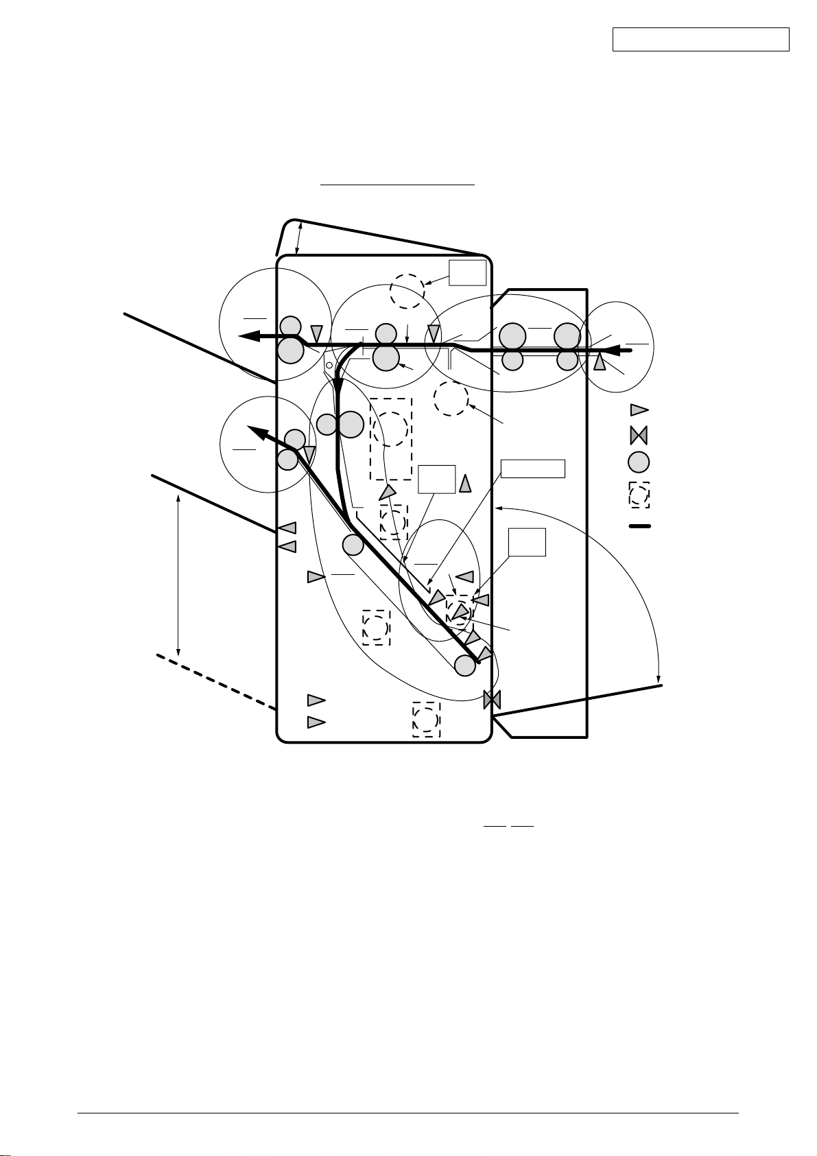
Numbers are error code
Upper cover (no sensor)
Oki Data CONFIDENTIAL
Bin 1 (face up)
Bin 2 (face down)
JAM 06
366
JAM 07
367
g
Invert
path
JAM 05
365
B
c
F
Punch
unit
K
H
JAM 02
362
Paper Feed Knob
Accumulator
Staple
path
J
L
G
D
JAM 01
361
A
Sensor
Switch
Roller
Motor
Paper path
f
JAM 03
C
363
d
M
E
R
364
N
JAM 04
Punch
a
Q
e
b
O
P
h
I
Figure 5.5.2 The position which paper-Jam occurs
*See the Numbers with under line(361-367).
Lower cover
41388601TH Rev.6 78 /
Page 79
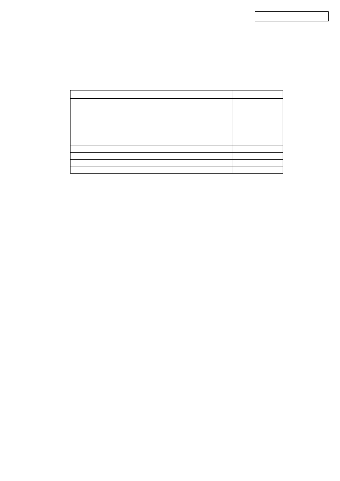
5.5.2 LCD message troubleshooting
(1) LCD Message
The message on the LCD (liquid crystal display) tells the problem situation of the printer.
Implement the appropriate troubleshooting base on the message.
No. Problem Flowchart Number
1 The printer does not work normally after being turned on. 1
2 JAM Error
Paper Input Jam (1st Tray) 2-1
Paper Input Jam (MT) 2-2
Paper Feed Jam 2-3
Paper Eject Jam 2-4
DUPLEX Jam 2-5
3 Paper Size Error 3
4 I/D Unit Up/Down Error 4
5 Fuser Unit Error 5
6 Fan Motor Error 6
Oki Data CONFIDENTIAL
Note:
When replacing the engine board (L73 PWB), demount the EEPROM chip from the old
board and remount it on the new one.
41388601TH Rev.6 79 /
Page 80

1 The printer does not work normally after turned on.
• Turn off the printer, wait a few seconds, then turn it on again.
• Is displayed on the LCD (for about 1 second)?
• No Is the AC cable connected correctly?
No Connect the AC cable correctly.
▼
• Yes Is +5V supplied to the PANEL connector pins on the PU board (K73 PWB)?
+5V: Pin 5 0V: Pin 2
Yes Is the operator panel cable connected correctly?
No Connect the cable correctly.
▼
Yes Replace the operator panel cable. Recovered?
No Replace the cover assembly of the operator panel.
▼
Yes End
Oki Data CONFIDENTIAL
▼
• No Is +5V supplied on the POWER connector of the engine board (K73 PWB)?
Pin 11,12, 13, 14: +5V Pin 3, 4, 5, 6, 23, 24, 25, 26, 27, 28, 29, 30: 0V
No Check the connection of the POWER connector, or replace the low-voltage power
supply unit.
▼
• Yes Replace the engine board.
▼
• Yes Are the following voltages supplied to the PU connector of the main board?
Pin 137-147, 187-197: +5V Pin 125-136, 175-186: +3.3V
Pin 148, 198: +12V Pin 101-124, 149-174, 199, 200: 0V
Yes Is the main board assy inserted correctly?
No Insert it correctly.
Yes Replace the main board.
▼
• No Are the following voltages supplied on the POWER connector of the engine board?
Pin 11, 12, 13, 14: +5V Pin 15, 16, 17, 18: +3.3V
Pin 1: +12V Pin 2: -12V Pin 7, 8, 9, 10: +32V
Pin 3, 4, 5, 6, 25, 26, 27, 28: 0V
Yes Replace the engine board.
▼
• No Replace the low-voltage power supply unit.
41388601TH Rev.6 80 /
Page 81

Oki Data CONFIDENTIAL
2-1 Paper Input Jam (1st Tray)
• Does the jam occur soon after the printer is turned on?
• Yes Is the paper jammed at the entrance cassette sensor or the entrance MT sensor ?
* MT : Multipurpose Tray
Yes Remove the jammed paper.
A
▼
• No Do the sensor levers (of the entrance cassette sensor and the entrance MT sensor) operate
normally?
No Replace the defective sensor lever.
▼
• Yes Do the sensors (the entrance cassette sensor and the entrance MT sensor) work properly?
(Operate each sensor lever and verify the signal on the FSENS connector pins on the PU
board (K73 PWB).)
Pin 4: Entrance cassette sensor, Pin 2: Entrance MT sensor
No Check the signal cable connection, or replace the sensor board (R71 PWB).
▼
• Yes Check the signal cable connection, or replace the engine board (K73 PWB).
▼
• No Does the paper jam occur immediately after the paper is fed?
• Yes Does the paper reach the entrance cassette sensor or the entrance MT sensor?
Yes Go to .
▼
• No Replace the feed roller or the Retard Pad assy in the paper tray.
▼
• No Is the feed motor rotating?
A
Yes Replace the feed roller.
▼
• No Is the resistance of the feed motor at the rated value (approx. 7.9 or 8.4 Ω)?
No Replace the feed motor.
▼
• Yes Is +32V supplied to the POWER connector Pins 7~10 on the engine board?
No Replace the low-voltage power supply unit.
▼
• Yes Check gear engagement and cable connection, or replace the engine board.
41388601TH Rev.6 81 /
Page 82

2-2 Paper Input Jam (Multipurpose Tray (MT))
• Does the paper jam occur immediately after the printer is powered on?
• Yes Is the paper jammed at the entrance cassette sensor or the entrance MT sensor ?
Yes Remove the paper jam.
▼
A
• No Does the lever of the entrance MT sensor operate normally?
No Replace the defective sensor lever.
▼
• Yes Does the entrance MT sensor work properly?
(Operate the sensor lever and confirm that the sensor works properly with the signal on the
FSENS connector pin on the engine board (K73 PWB).)
Pin 2: Entrance MT sensor
No Check the connection of the signal cable, or replace the sensor board (R71 PWB).
▼
• Yes Check the signal cable connection, or replace the engine board.
Oki Data CONFIDENTIAL
▼
• No Does the paper jam occur immediately after paper is fed?
• Yes Does the paper reach the entrance MT sensor ?
Yes Go to .
▼
• No Replace the multipurpose tray assembly.
▼
• No Does the registration motor rotate properly?
A
• No Is +32V supplied to the POWER connector Pins 7~10 on the engine board?
No Replace the low-voltage power supply unit.
▼
• Yes Check the connection of cables, or replace the engine board.
▼
• Yes Go to 2-3 Paper Feed Jam.
41388601TH Rev.6 82 /
Page 83

2-3 Paper Feed Jam
• Does the paper jam occur immediately after the printer is powered on?
• Yes Is the paper jammed at the entrance belt sensor?
Yes Remove the jammed paper.
▼
• No Does the lever of the write sensor work right?
A
No Replace the lever of the write sensor.
▼
• Yes Does the entrance belt sensor work properly?
(Operate the sensor lever and verify the signal on the FSENS connector pin on the engine
board (K73 PWB).)
Pin 6: Entrance belt sensor
No Check the connection of the cable, or replace the sensor board (R71 PWB).
▼
• Yes Check the signal cable connection. Is it attached properly?
Oki Data CONFIDENTIAL
No Connect the cable properly.
▼
• Yes Replace the engine board.
▼
• No Does the paper jam occur immediately after paper is fed?
• Yes Does the paper reach the write sensor?
Yes Go to .
▼
• No Is the registration motor rotating?
A
• No Is the resistance of the registration motor at the rated value (approx. 7.9 Ω)?
No Replace the registration motor.
▼
• Yes Check the gear engagement, or replace the engine board.
▼
• Yes Replace the resistration roller (A) or (B).
▼
• No Does the paper jam occur when paper is loaded?
• Yes Does the belt motor rotate properly?
• No Is the resistance of the belt motor at the rated value (approx. 7.9 Ω)?
No Replace the belt motor.
▼
• Yes Check gear engagement, or replace the engine board.
▼
• Yes Check gear engagement, or replace the belt assy.
▼
• No End
41388601TH Rev.6 83 /
Page 84

2-4 Paper Eject Jam
• Does the paper jam occur immediately after the printer is powered on?
• Yes Is the paper jammed at the ejection sensor?
Yes Remove the jammed paper.
▼
• No Does the lever of the ejection sensor operate normally?
No Replace the ejection sensor lever.
▼
• Yes Does the ejection sensor work properly?
(Operate the sensor lever and confirm that the sensor works properly or verify the signal on
the PARTTEMP connector Pin 8 on the engine board (K73 PWB).)
Pin 8: Ejection sensor
No Check the signal cable connection, or replace the ejection sensor.
▼
• Yes Replace the engine board.
Oki Data CONFIDENTIAL
▼
• No Dose the heat motor rotate properly?
• No Is the resistance of the heat motor at the rated value (approx. 7.9 Ω)?
No Replace the heat motor.
▼
• Yes Is +32V supplied to the POWER connector Pins 7~10 on the engine board?
No Replace the low-voltage power supply unit.
▼
• Yes Check the connection of the cables, or replace the engine board.
▼
• Yes Does the paper separator operate normally?
• No Does the paper separator solenoid work normally?
No Check the cable connection, or replace the solenoid or the engine board.
▼
• Yes Replace the paper separator assy.
▼
• Yes Replace the eject guide assy.
41388601TH Rev.6 84 /
Page 85

Oki Data CONFIDENTIAL
2-5 DUPLEX jam
• Does the paper jam occur immediately after the printer is turned on?
• Yes Is the paper jammed at the in sensor, rear sensor or front sensor in the DUPLEX unit?
Yes Remove the jammed paper.
▼
• No Do the in sensor, rear sensor and front sensor in the DUPLEX unit operate properly?
No Replace the defective sensor.
▼
• Yes Check the cable connections at the in sensor, rear sensor and front sensor of the DUPLEX
unit, or replace the DUPLEX unit board (V73 PWB).
▼
• No Does the paper jam occur immediately after paper is fed into the DUPLEX unit?
• Yes Is the DUPLEX motor rotating?
No Replace the DUPLEX motor.
▼
• Yes Check gear engagement or replace the DUPLEX board (V73 PWB).
▼
• Yes Replace the DUPLEX unit.
41388601TH Rev.6 85 /
Page 86

3 Paper Size Error
• Is paper in the specified size used?
No Use paper that complies with the specification.
Yes Is the paper jammed at the entrance MT sensor or at the paper width sensor?
Yes Remove the jammed paper.
▼
• Yes Does the lever of the entrance MT sensor operate normally?
No Replace the defective sensor lever.
▼
• Yes Does the entrance MT sensor work properly?
(Operate the sensor lever and verify the signal on the FSENS connector pin on the engine
board (K73 PWB).)
Pin 4: Entrance MT sensor
No Check cable connection, or replace the sensor board (R71 PWB).
Oki Data CONFIDENTIAL
▼
• Yes Does the lever of the entrance belt sensor operate normally?
No Replace the defective sensor lever.
▼
• Yes Does the entrance belt sensor work properly?
(Operate the sensor lever and confirm that the sensor works properly, verify the signal on
the FSENS connector pin on the engine board (K73 PWB).)
Pin 6: Entrance belt sensor
No Check cable connection or replace the sensor board (R71 PWB).
▼
• Yes Do all the paper-size detecting switches on the size detecting board (B73 PWB) work right?
(Press the paper-size detecting switches and verify the signal on the engine board PSIZE
connector pins.)
Pin 3: Paper size detector 1
Pin 4: Paper size detector 2
Pin 5: Paper size detector 3
Pin 6: Paper size detector 4
No Check cable connection, or replace the size detecting board (B73 PWB).
▼
• Yes Check cable connection, or replace the engine board.
41388601TH Rev.6 86 /
Page 87

Oki Data CONFIDENTIAL
4 Image Drum Unit (IDU) Up/Down Error
• Turn off the printer, wait a few seconds, then turn it on again.
• Does each drum unit rotate properly while printing?
• No Is the resistance of the IDU motor at the rated value (approx. 4.0 Ω)?
No Replace the defective IDU motor.
▼
• Yes Is +32V supplied to the POWER connector Pins 7~10 on the engine board?
No Replace the low-voltage power unit.
▼
• Yes Check cable connection, or replace the engine board.
▼
• Yes Does the IDU sensor lever work adequately?
• No Check gear engagement and the sensor lever operation, or replace the defective gear or
sensor lever.
▼
• Yes Does the IDU sensor operate properly?
Verify the signal on the JODEN connector pins on the driver board (K73 PWB).
Pin 4: IDU sensor cyan
Pin 14: IDU sensor black
Pin 2: IDU sensor magenta
Pin 12: IDU sensor yellow
No Replace the junction board (N73 PWB).
▼
• Yes Check the cable connection between the junction board (N73 PWB) and engine board (K73
PWB), or replace the engine board.
41388601TH Rev.6 87 /
Page 88
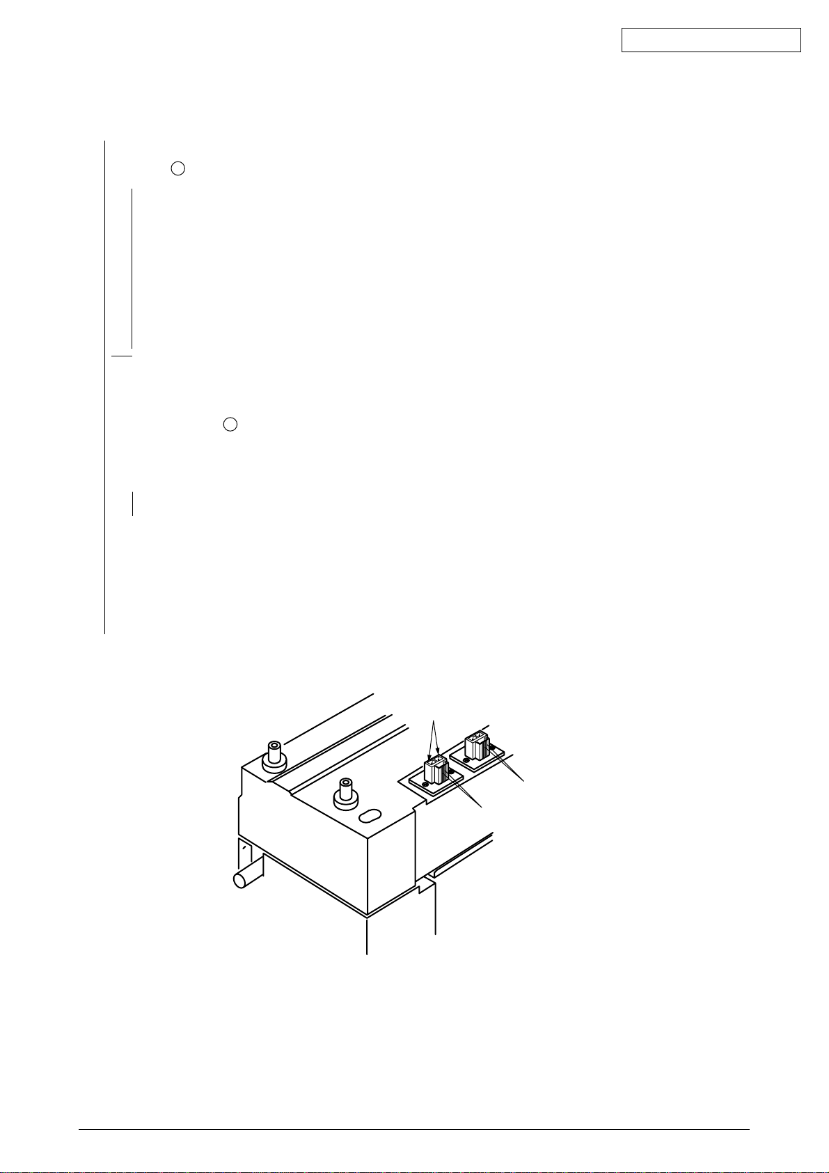
5 Fuser Unit Error
• Does the fuser error occur immediately after the printer is turned on?
A
• Yes Does the heat roller thermistor have a open or short circuit? (See Figure 5.1.)
(at room temperature 0 °C~ 43 °C, approx. 190 ~ 980 Ω)
Yes Replace the fuser unit.
▼
• No Does the back-up roller thermistor have a open or short circuit? (See Figure 5.1.)
(at room temperature 0 °C~ 43 °C, approx. 190 ~ 980 Ω)
Yes Replace the fuser unit.
▼
▼
• No
▼
• No Does the fuser error occur about 3 min. after the printer is turned on?
Oki Data CONFIDENTIAL
• No Go to .
▼
• Yes Is the fuser’s heater on? (Does it get hot?)
A
• Yes Replace the engine board.
▼
• No Replace the fuser unit.
▼
• No Does AC voltage appear between CN1 connector Pin 1 and Pin3 of the low-voltage power
supply unit?
No Replace the low-voltage power supply unit.
▼
• Yes Replace the fuser unit.
Halogen Lamp
Back-up Roller Thermistor
Heat Roller Thermistor
Bottom part of Fuser Unit
Figure 5.1
41388601TH Rev.6 88 /
Page 89

Oki Data CONFIDENTIAL
6 Fan Motor Error
• Does the fan of the low-voltage power supply unit rotate after the printer is turned on?
• Yes Does the error recur after the fan of the low-voltage power supply unit has been replaced?
• Yes Replace the low-voltage power supply unit.
▼
• No End
▼
• Yes Does the engine board fan rotate after the printer is turned on?
• No Is +32V supplied to the FAN connector Pin 1 on the engine board (K73 PWB)?
• No Is +32V supplied to the POWER connector pins on the engine board (K73 PWB)?
+32V: Pin 7, 8, 9, 10
No Check cable connection or replace the low-voltage power supply unit.
▼
• Yes Replace the engine board.
▼
• Yes Replace the fan of the engine board.
▼
• Yes Does the fuser fan rotate after the printer is turned on?
• No Is +32V supplied to the JOBOFF connector Pin 5 on the engine board (K73 PWB)?
• No Is +32V supplied to the POWER connector pins on the engine board (K73 PWB)?
+32V: Pin 7, 8, 9, 10
No Check cable connection, or replace the low-voltage power supply unit.
▼
• Yes Replace the engine board.
▼
• Yes Replace the fuser fan.
▼
• Yes End
41388601TH Rev.6 89 /
Page 90
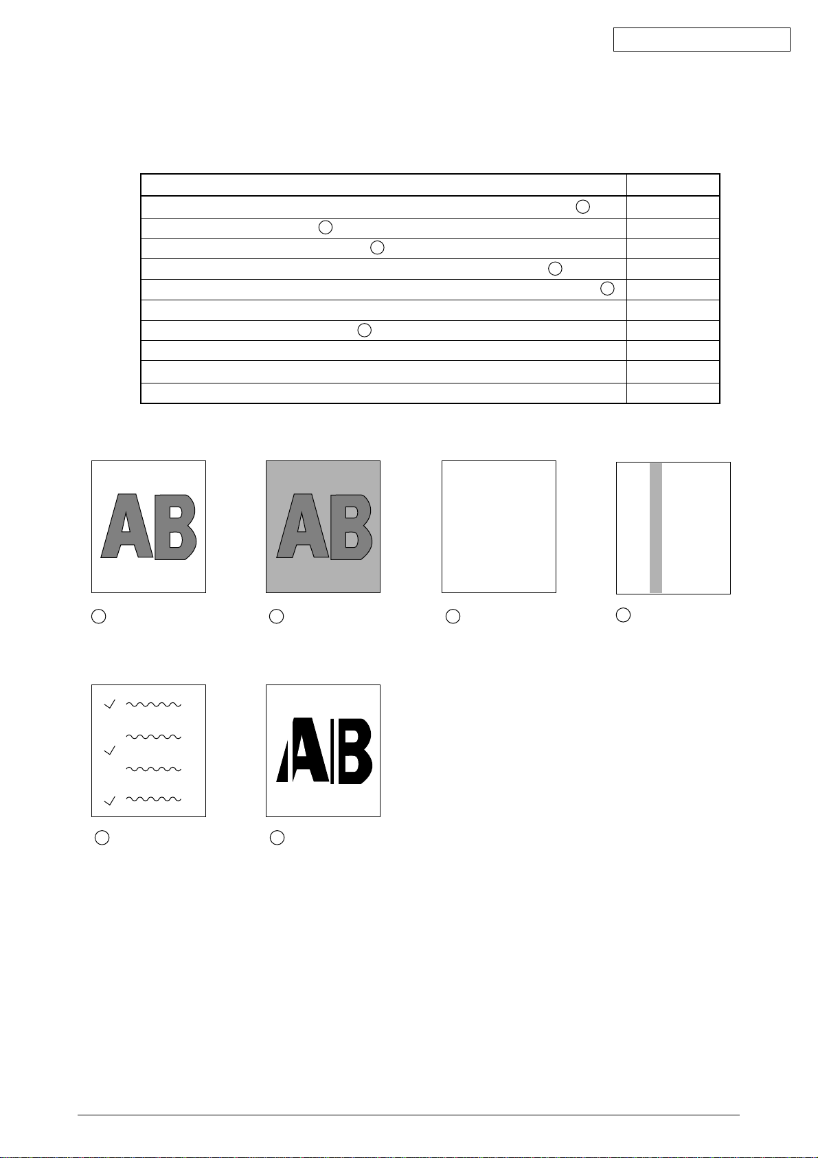
5.5.3 Image troubleshooting
When the printout images are not satisfactory as shown below, follow the troubleshooting
procedures given in this section.
Light or blurred images, or images in inappropriate color tone (Figure 5.2- A ) 1
Dark background (Figure 5.2- B ) 2
No images on print output (Figure 5.2- C ) 3
Band/stripes in black or color in the longitudinal direction (Figure 5.2- D ) 4
Band/stripes in white or irregular color in the longitudinal direction (Figure 5.2- F ) 5
Poor fusing (Images are blurred or peeled off when touched with a hand.) 6
Cyclical printout defects (Figure 5.2- E ) 7
Missing characters 8
Color misalignment 9
Printout colors different from the original 0
Oki Data CONFIDENTIAL
Printout problem Flowchart No.
A
Light or blurred
images as a whole
E
Cyclical defect
B
Dark background
density
White belts or
F
streaks in the
vertical direction
C
Figure 5.2
Blank paper
D
Black stripes in the
vertical direction
41388601TH Rev.6 90 /
Page 91

Oki Data CONFIDENTIAL
1 Light or blurred images or images in inappropriate color tone on the whole printout area
(Figure 5.2- A )
• Is toner low? (Is the message "Toner Low" displayed?)
Yes Supply toner.
▼
• No Is the specified paper used?
No Use the specified paper.
▼
• Yes Is the lens of the LED head dirty?
Yes Clean the LED head lens.
▼
• No Is each LED head assy connected properly to the junction board (Y71 PWB) and engine
board (K73 PWB)?
No Check the cable connection (between each LED head and the engine board) and connect
the cable between the LED head and the engine board properly.
▼
• Yes Is +3.8V supplied to the following POWER connector pins on the junction board(Y71 PWB)?
+3.8V: Pins 1, 2, 3, 4, 5, 6, 7 and 8
• Yes Is +3.8V supplied to each LED head assy from the junction board (Y73 PWB)?
YPOW connector Pin 3: LED head assy yellow
MPOW connector Pin 3: LED head assy magenta
CPOW connector Pin 3: LED head assy cyan
BPOW connector Pin 3: LED head assy black
No Replace the junction board (Y71 PWB).
▼
• Yes Check the cable connection, or replace the LED head assy.
▼
• No Check the cable connection, or replace the low-voltage power supply unit. Recovered?
Yes End
▼
• No Is +32V supplied to the POWER connector pins on the engine board (K73 PWB)?
+32V: Pins 7, 8, 9 and 10
No Check cable connection, or replace the low-voltage power supply unit.
▼
• Yes Is +32V supplied to the HVOLT connector Pin 5 on the engine board (K73 PWB)?
No Replace the engine board.
▼
• Yes Check the cable connection, replace the high-voltage power unit, or belt cassette assembly.
Recovered?
Yes End
▼
• No Is each ID terminal connected correctly to the contact assembly? (See Figure 5.3.)
No Connect the ID terminals with the contact assembly correctly.
▼
• Yes Replace the ID unit.
Notes: 1. When replacing the engine board (K73 PWB), demount the EEPROM chip from the old
engine board and remount it on the new one.
2. In case the EEPROM chip is not replaced, see Item (2) in Sec. 5.5.2.
41388601TH Rev.6 91 /
Page 92

2 Dark background (Figure 5.2- B )
• Was each ID exposed to external light for a long time?
Oki Data CONFIDENTIAL
Yes Replace the ID unit.
▼
• No Are the rollers in the fuser unit contaminated?
Note:
Reset the counter after replacement.
Yes Replace the fuser unit.
▼
• No Adjust the setting of “MEDIA TYPE”.
Light: 60 g/sq.m. Med. light: 64~74 g/sq.m. Medium: 75~90 g/sq.m.
Med. heavy: 91~104 g/sq.m. Heavy: 105~122 g/sq.m. Ultra heavy: 123~175 g/sq.m.
No Set the “MEDIA TYPE” properly.
▼
• No Is each LED head assy connected to the junction board(Y71 PWB) correctly?
No Connect each LED head assy to the junction board(Y71 PWB) appropriately.
▼
• Yes Is +3.8V supplied to the following POWER connector pins on the junction board (Y71 PWB)?
+3.8 V: Pins 1, 2, 3, 4, 5, 6, 7 and 8
• Yes Is +3.8V supplied to the following cable connector pins between the junction board (Y71
PWB) and each LED head assy?
YPOW connector Pin 3: LED head assy yellow
MPOW connector Pin 3: LED head assy magenta
CPOW connector Pin 3: LED head assy cyan
BPOW connector Pin 3: LED head assy black
No Replace the junction board(Y71 PWB).
▼
• Yes Check the cable connection, or replace the LED head assy.
▼
• No Check the cable connection, or replace the low-voltage power supply unit. Recovered?
Yes End
▼
• No Is +32V supplied to the POWER connector pins on the engine board (K73 PWB)?
+32V: Pins 7, 8, 9 and 10
No Check the cable connection, or replace the low-voltage power supply unit.
▼
• Yes Is +32V supplied to the POWER connector pins of the engine board (K73 PWB)?
No Replace the engine board.
▼
• Yes Check the cable connection, or replace the high-voltage power supply unit or belt cassette
assy. Recovered?
Yes End
▼
• No Is each ID terminal connected to the contact assembly correctly? (See Figure 5.3)
No Connect the ID terminals with the contact assembly correctly.
▼
• Yes Replace the ID unit.
Notes: When replacing the engine board (K73 PWB), demount the EEPROM chip from the old
engine board and remount it on the new one.
41388601TH Rev.6 92 /
Page 93

Oki Data CONFIDENTIAL
3 Blank paper (Figure 5.2- C )
• Is each LED head assembly connected to the junction board (Y71 PWB) and Engine board (K73
PWB)correctly?
No Check the cable connection the LED assembly with the junction board (Y71 PWB) and
engine board.
▼
• Yes Is +3.8V supplied to the following POWER connector pins on the junction board (Y71 PWB)?
+3.8V: Pin 1, 2, 3, 4, 5, 6, 7, 8
• Yes Is +3.8V supplied to the following cable connector pins between the junction board (Y71
PWB) and each LED head assembly?
YPOW connector Pin 3 : LED head assembly yellow
MPOW connector Pin 3 : LED head assembly magenta
CPOW connector Pin 3 : LED head assembly cyan
BPOW connector Pin 3 : LED head assembly black
No Replace the junction board (Y71 PWB).
▼
• Yes Check the cable connection, or replace the LED head assembly.
▼
• No Is +32V supplied to the POWER connector pins of the engine board (K73 PWB)?
+32V: Pin 7, 8, 9, 10
No Check the cable connection, or replace the low-voltage power supply unit.
▼
• Yes Is +32V supplied to the HVOLT connector Pin 5 of the engine board (K73 PWB)?
No Replace the engine board.
▼
• Yes Check the cable connection, or replace the high-voltage power supply unit or belt cassette
assembly. Recovered?
Yes End
▼
• No Is each ID terminal connected to the contact assembly correctly? (See Figure 5.3)
No Connect the ID terminals with the contact assembly correctly.
▼
• Yes Replace the ID unit.
Notes: 1. When replacing the engine board (K73 PWB), demount the EEPROM chip from the old
engine board and remount it on the new one.
2. In case the EEPROM chip is not replaced, see Item (2) in Sec. 5.5.2.
41388601TH Rev.6 93 /
Page 94

Oki Data CONFIDENTIAL
4 Band/stripes in black or color in the longitudinal direction (Figure 5.2- D )
• Is each LED head assembly connected to the junction board (Y71 PWB) correctly?
No Connect the LED head assembly to the junction board correctly.
▼
• Yes Check the cable connection, or replace the LED head assembly. Recovered?
Yes End
▼
• No Check the cable connection, or replace the junction board (Y71 PWB). Recovered?
Yes End
▼
• No Is the engine board (K73 PWB) connected with the junction board (Y71 PWB) correctly?
No Connect the engine board with the junction board correctly.
▼
• Yes Check the cable connection, or replace the engine board (K73 PWB). Recovered?
Yes End
▼
• No Is each ID terminal connected to the contact assembly correctly? (See Figure 5.3)
No Connect the ID terminals with the contact assembly correctly.
▼
• Yes Replace the ID unit.
Notes: 1. When replacing the engine board (K73 PWB), demount the EEPROM chip from the old
engine board and remount it on the new one.
2. In case the EEPROM chip is not replaced, see Item (2) in Sec. 5.5.2
41388601TH Rev.6 94 /
Page 95

Oki Data CONFIDENTIAL
5 Band/stripes in white or irregular color in the longitudinal direction (Figure 5.2- F )
• Is each LED head lens contaminated?
Yes Clean the LED head lens.
▼
• No Is each LED head assembly connected to the junction board (Y71 PWB) correctly?
No Connect the LED head assembly to the junction board (Y71 PWB) correctly.
▼
• Yes Check the cable connection, or replace the LED head assembly. Recovered?
Yes End
▼
• No Check the cable connection, or replace the junction board (Y71 PWB). Recovered?
Yes End
▼
• No Is the engine board (K73 PWB) connected with the junction board correctly?
No Connect the engine board with the junction board correctly.
▼
• Yes Check the cable connection, or replace the engine board (K73 PWB). Recovered?
Yes End
▼
• No Is each ID terminal connected to the contact assembly correctly? (See Figure 5.3)
No Connect the ID terminals with the contact assembly correctly.
▼
• Yes Replace the ID unit.
Notes: 1. When replacing the engine board (K73 PWB), demount the EEPROM chip from the old
engine board and remount it on the new one.
2. In case the EEPROM chip is not replaced, see Item (2) in Sec. 5.5.2
41388601TH Rev.6 95 /
Page 96

Oki Data CONFIDENTIAL
6 Poor fusing (Images are blurred or peeled off when touched with a hand.)
• Is the specified paper used?
No Use the proper paper.
▼
• Yes Is the contact of the fuser unit connected correctly?
No Connect the contact of the fuser unit properly.
▼
• Yes Are the rollers in the fuser unit contaminated?
Yes Replace the fuser unit.
▼
• No Is the “MEDIA TYPE” (MENU 1) set correctly?.
Light: 60 g/sq.m. Med. light: 64~74 g/sq.m. Medium: 75~90 g/sq.m.
Med. heavy: 91~104 g/sq.m. Heavy: 105~122 g/sq.m. Ultra heavy: 123~175 g/sq.m.
No Set the proper “MEDIA TYPE”.
▼
• Yes Does AC voltage appear between the CN connector Pin 1 and Pin 3 of the low-voltage power
supply unit?
No Replace the low-voltage power supply unit.
▼
• Yes Is the resistance of the heat roller thermistor within the rated value? (See the Figure 5.1)
(at room temperature 0 °C~ 43 °C, approx. 190 ~ 980 Ω)
No Replace the fuser unit.
▼
• Yes Is the resistance of the back-up roller thermistor within the rated value? (See the Figure 5.1)
(at room temperature 0 °C~ 43 °C, approx. 190 ~ 980 Ω)
No Replace the fuser unit.
▼
• Yes Is the THERM1 signal on the THERM connector Pin 6 on the engine board (K73 PWB) within
the range below?
No Replace the fuser unit assy.
▼
• Yes Replace the fuser unit assy.
Notes: 1. When replacing the engine board (K73 PWB), demount the EEPROM chip from the old
engine board and remount it on the new one.
2. In case the EEPROM chip is not replaced, see Item (2) in Sec. 5.5.2
41388601TH Rev.6 96 /
Page 97

7 Cyclical printout defects (Figure 5.2- E )
Cycle Defective Part Solution
94.3 mm Image Drum Replace the ID unit.
49.6 mm Developing Roller Replace the ID unit.
67.6 mm Toner Supply Roller Replace the ID unit.
44.0 mm Charge Roller Replace the ID unit.
113 mm Fuser Roller Replace the fuser unit.
57.8 mm Transfer Roller Replace the belt cassette assembly.
Oki Data CONFIDENTIAL
Note:
After replacement of the ID unit, fuser unit or belt cassette unit, the corresponding counter
must be reset in the user maintenance mode.
41388601TH Rev.6 97 /
Page 98

Oki Data CONFIDENTIAL
8 Missing characters
• Is each LED head lens contaminated?
Yes Clean the lens of LED head.
▼
• No Is each LED head assembly connected to the junction board (Y71 PWB) correctly?
No Check the cable connection, and connect the LED head to the junction board correctly.
▼
• Yes Is +3.8V supplied to the following HEADPOW connector pins of the junction board (Y71
PWB)?
+3.8V: Pin 1, 2, 3, 4, 5, 6, 7, 8
• Yes Is +3.3V supplied to each LED head assembly from the junction board (Y71 PWB)?
YPOW connector Pin 3 : LED head assembly yellow
MPOW connector Pin 3 : LED head assembly magenta
CPOW connector Pin 3 : LED head assembly cyan
BPOW connector Pin 3 : LED head assembly black
No Replace the junction board (Y73 PWB).
▼
• Yes Check the cable connection, or replace the LED head assembly.
▼
• No Check the cable connection, or replace the low-voltage power supply unit. Recovered?
Yes End
▼
• No Is +32V supplied to the POWER connector of the engine board (K73 PWB)?
+32V: Pin 7, 8, 9, 10
No Check the cable connection, or replace the low-voltage power supply unit.
▼
• Yes Is +32V supplied to the HVOLT connector pin 5 of the engine board (K73 PWB)?
No Replace the engine board.
▼
• Yes Check the cable connection, replace the high-voltage power supply unit or belt cassette
assembly. Recovered?
Yes End
▼
• No Is each ID terminal connected to the contact assembly correctly? (See Figure 5.3)
No Connect the ID terminals with the contact assembly correctly.
▼
• Yes Replace the ID unit.
Notes: 1. When replacing the engine board (K73 PWB), demount the EEPROM chip from the old
engine board and remount it on the new one.
2. In case the EEPROM chip is not replaced, see Item (2) in Sec. 5.5.2
41388601TH Rev.6 98 /
Page 99

Oki Data CONFIDENTIAL
9 Color Misalignment
• Is any of the following gears broken? (Gear assy of ID unit, Multipurpose Tray, belt unit and belt motor)
Yes Replace the broken gear assembly.
▼
• No Is each LED head unit connected to the junction board (Y71 PWB) correctly?
No Connect the LED head unit correctly with the junction board.
▼
• Yes Check the cable connection, or replace the LED head assembly. Recovered?
Yes End
▼
• No Check the cable connection, or replace the junction board (Y71 PWB). Recovered?
Yes End
▼
• No Is engine board (K73 PWB) connected to the junction board (Y71 PWB) correctly?
No Connect the boards correctly.
▼
• Yes Check the cable connection, or replace the EEPROM of the engine board. Recovered?
Yes End
▼
• No Replace the engine board. Recovered?
Yes End
▼
• No Is each ID terminal connected to the contact assembly correctly? (See Figure 5.3)
No Connect the ID terminals with the contact assembly correctly.
▼
• Yes Replace the ID unit.
Notes: 1. When replacing the engine board (K73 PWB), demount the EEPROM chip from the old
engine board and remount it on the new one.
2. In case the EEPROM chip is not replaced, see Item (2) in Sec. 5.5.2
41388601TH Rev.6 99 /
Page 100

Oki Data CONFIDENTIAL
0 Printout colors different from the original
• Is each LED head lens contaminated?
Yes Clean the LED head lens.
▼
• No Is each LED head assembly connected to the junction board (Y73 PWB) correctly?
No Check the cable connection (between each LED head and the junction board) and connect
the LED assy to the junction board correctly.
▼
• Yes Is +3.8V supplied to the following HEADPOW connector pins of the junction board (Y71
PWB)?
+3.8V: Pin 1, 2, 3, 4, 5, 6, 7, 8
• Yes Is +3.8V supplied to each LED head assembly from the junction board (Y71 PWB)?
YPOW connector Pin 3 : LED head assembly yellow
MPOW connector Pin 3 : LED head assembly magenta
CPOW connector Pin 3 : LED head assembly cyan
BPOW connector Pin 3 : LED head assembly black
No Replace the junction board (Y71 PWB).
▼
• Yes Check the cable connection, or replace the LED head assembly.
▼
• No Check the cable connection, or replace the low-voltage power supply unit. Recovered?
Yes End
▼
• No Is +32V supplied to the POWER connector of the engine board (K73 PWB)?
+32V; Pin 7, 8, 9, 10
No Check the cable connection, or replace the low-voltage power supply unit.
▼
• Yes Is +32V supplied to HVOLT connector pin 5 of the engine board (K73 PWB)?
No Replace the engine board.
▼
• Yes Check the cable connection, replace the high-voltage power supply unit or belt cassette
assembly. Recovered?
Yes End
▼
• No Is each ID terminal connected to the contact assembly correctly? (See Figure 5.3)
No Connect the ID terminals with the contact assembly correctly.
▼
• Yes Replace the ID unit.
Notes: 1. When replacing the engine board (K73 PWB), demount the EEPROM chip from the old
engine board and remount it on the new one.
2. In case the EEPROM chip is not replaced, see Item (2) in Sec. 5.5.2
41388601TH Rev.6 100 /
 Loading...