

Page 1
Page 2

Page 3

FCC WARNING
You are cautioned that changes or modifications not expressly approved by the
party responsible for compliance could void your authority to operate the
equipment.
This device complies with Part 15 of the FCC Rules. Operation is subject to the
following two conditions: (1) this device may not cause harmful interference,
and (2) this device must accept any interference received, including
interference that may cause undesired operation.
This equipment has been tested and found to comply with the limits for a Class
B digital device, pursuant to Part 15 of the FCC Rules. These limits are
designed to provide reasonable protection against harmful interference in a
residential installation. This equipment generates, uses and can radiate radio
frequency energy and, if not installed and used in accordance with the
instructions, may cause harmful interference to radio communications.
However, there is no guarantee that interference will no t occ ur in a particular
installation.
If this equipment does cause harmful interference to radio or television
reception, which can be determined by turning the equipment off and on, the
user is encouraged to try to correct the interference by one or more of the
following measures:
- Reorient or relocate the receiving antenna.
- Increase the separation between the equipment and receiver.
- Connect the equipment into an outlet on a circuit different from that to which
the receiver is connected.
- Consult the dealer or an experienced radio/TV technician for help.
AC power cord with ferrite core must be used for RF interference suppression.
Page 4

◆ Contents ◆
Name of Parts ............................... 2
Power .............................................. 6
Computer Connection ................... 8
Paper Setting ................................. 9
Ribbon Setting ..........………….. 11
Does not print correctly .............. 13
When error light is ON ............... 14
Failure? .................. .............. ....... 15
Page 5
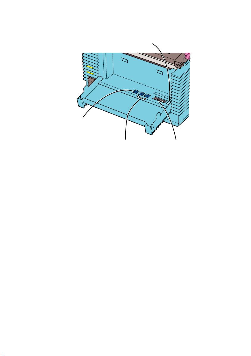
Name of Parts
■Front View
Top cover
Paper check
window
Operation switch
Power switch
Front cover
■Top cover .................... Open th is co ver whe n you set th e pa pe r.
■ Power switch .............. Press th i s sw it c h to t u rn O N/ OF F t h e p ri n te r.
■ Paper check window ... To check the status of paper.
■ Front cover ................. Open this cover to refill or set DIP-SW.
■ Operation switch
2
• POWER .... When you turn on the power, the green light lights up. Refer to
“Starting/Power”.
• ERR OR ..... When an erro r o c c u r s , t h e re d light turns ON . Refer to
“When error light is ON”.
• ONLINE ... When the green light is ON, the printer can receive data. When
the light is OFF, the printer cannot receive.
• [ ONLINE ] button ... Press this b utton to stop rec eiving d ata. Res ume by
pressing this button again. If this button is pressed
while printing, the printing is suspended. To resume
printing, press this button again.
• [FEED] but t o n ........ When yo u press this butto n in the offline state, you
can feed paper. If you turn on the power of the printer
while you keep pressing this button, you can print out
the printer status.
Page 6
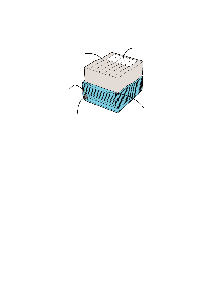
Back View
I/F Cover
Fanfold paper set in place
Optional interface
Connecter
■Power Connector ... Connects AC adapter.
■Optional interface Connecter ... Connects computer.
■Fanfold Paper set in place ...
Open this to use fanfold paper.To open the folder,
remove the Top Cover and release.
■I/F Cover ... It removes by exchange of an I/F board.
※
Handling of an I/F Cover:
Please close with an I/F Cover after shutting off a power supply and
attaching or removing an I/F board, in case an I/F Cover is opened.
Power
Connector
3
Page 7
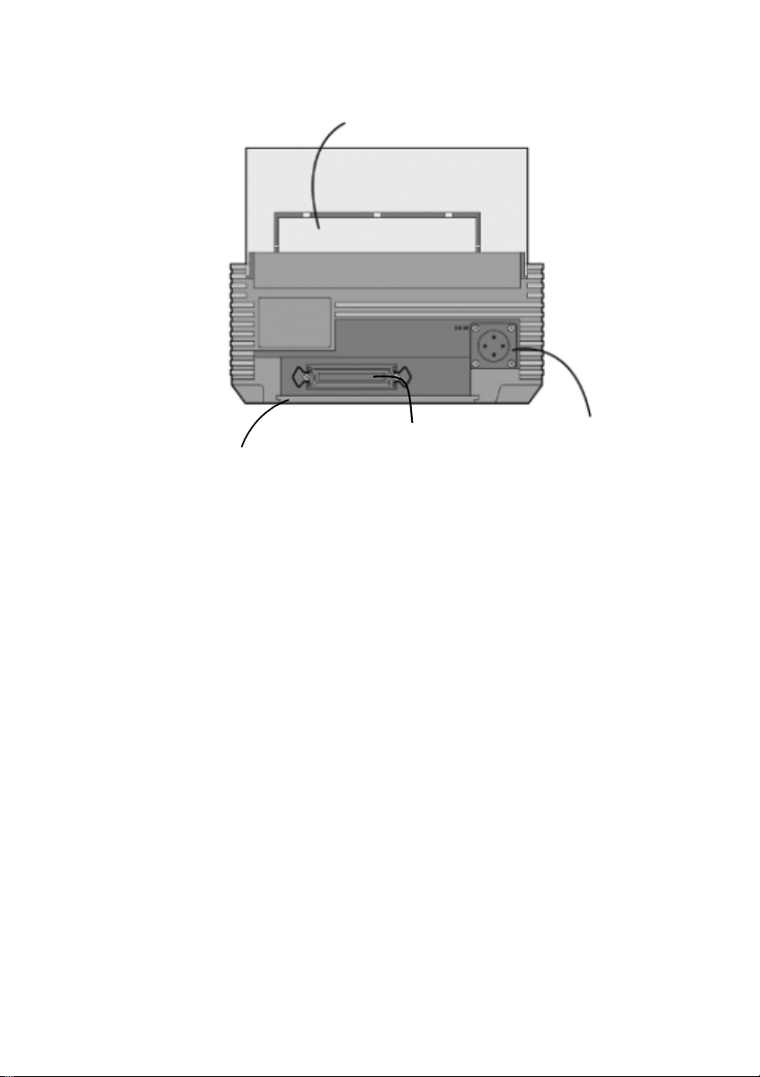
■ Top Cover Open
Thermal head
Head
Sensor
Platen roller
Head Open/Close lever
■ Paper holder ... When you use a roll paper, set the paper here. You can
adjust the width according to the paper size.
■ Paper holder slide lever .. Press this lever to adjust the paper holder wid th.
■ Head ................ Open this p a rt to re fill p a pe r.
■ Head Open/Close lever .. Press this to open the head.
■ Thermal head .... This is the printing area. Please keep this part clean.
■ Platen roller ...... Thi s is th e pa rt th at fe ed s p ap e r. Please kee p th i s p a rt
clean.
■ Sensor ................ Paper travels over this.
■ Driver for darkness adjustment ... This is used to change the print darkness.
4
Driver for darkness
adjustment
Paper holder
Paper holder
slide lever
Page 8
■ Front Cover Open
Error number display
Print darkness
adjustment volume
■ Print darkness adjustment volume .. You can finely adjust the darkness that
■ Sensor level ...... Do not use this. Only f o r u s ed by service p e r s o nnel.
■ DIP-SW ............ Appropri at e settings a r e se t according t o yo u r printer
system environment. You can change the settings. See the
manual for details.
■ Error number display .. When the error light is ON, check the displa yed
Sensor level DIP-SW
is set in the Printer Setting screen. See
the manual for details.
number. This number represents the re ason of the
error. See the manual for details.
5
Page 9
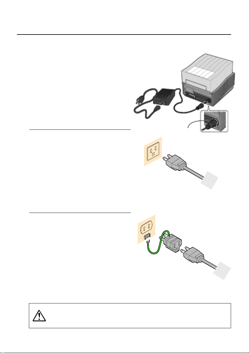
Power
Cable Connection
1 Connect the power cable with the
main unit and AC adapter as shown
in the figure. When you insert the
AC adapter in the main unit, set the
stopper firmly.
2 Plug in the power cable to the outlet.
3 Use a Two-prong adapter if only a
two-prong outlet is available.
1 Connect the power cable with the
main unit and AC adapter as shown
in the figure. When you insert the
AC adapter in the main unit, set the
stopper firmly.
2 Plug in the power cable to the outlet.
3 Use a Two-prong adapter if only a
two-prong outlet is available.
1 Connect the power cable with the
main unit and AC adapter as shown
in the figure. When you insert the
AC adapter in the main unit, set the
stopper firmly.
2 Plug in the power cable to the outlet.
3 Use a Two-prong adapter if only a
two-prong outlet is available.
Always make sure to ground the power cable to the ground connector,
otherwise electric shock may result. Construct the ground facility if it
is not available.
6
Stopper
Page 10
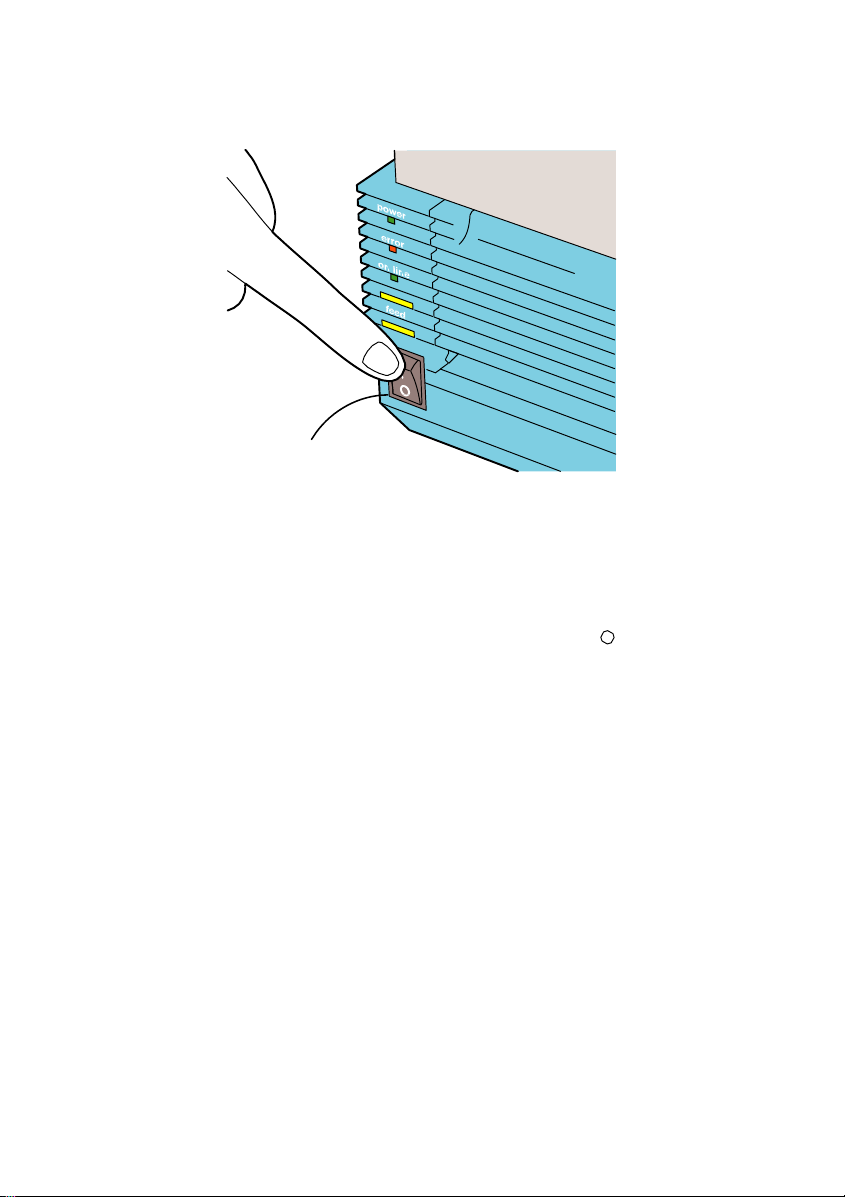
Power Switch
Press the power switch at the front side of the main unit in the “|” direction.
* When you turn on the power, the POWER light lights up. Please confirm
this.
When you turn off the printer, flip the switch to the “ ” direction.
Power Switch
7
Page 11

Computer Connection
Connection example using Bi-directional parallel interface
Use [Bi-directional parallel interfa ce( sold sepa ra tel y)].
This printer operates by being connected to a computer.
interface cable connecting the bi-directional parallel interface connector at
the rear panel of the printer.
* If you are using a different optional interface board, refer to the instructions of
8
Turn off the power of the printer and connect to the computer with an
its “Optional Interface”.
Page 12

Paper Setting
1 Confirm the [PUSH] mark on the
Left/Right side of the main unit.
While depressing the mark on the cover, open
the Top cover
2 Press the Head Open/Close lever to
the direction as shown in Figure.
Confirm that the head is detached from the
platen roller part, then lift the head in the
direction as shown in the Figure.
3 While pressing the paper holder slide
leve r, adjust the paper holder to the paper
size.
4 Set the paper on the paper holder.
9
Page 13

5 Pull the paper,then pass under the sensor.
6 Close the head to the home position.
7 Depress the [PUSH] mark with finger
until fixed firmly.
Close the To p cover.
8 Set the top of the paper by pressing the
[FEED] button.
Finally, press the [ONLINE] button to change
10
the online status.
Page 14

Ribbon Setting
Thermal Transfer model OKI POS T400/T410 only.
1 Confirm the [PUSH] mark on the Left/Right
side of the main unit.
While depressing the mark on the cover, open
the Top cover.
2 Press the Head Open/Close lever to the
direction as shown in Figure.
Confirm that the head is detached from the
platen roller part, then lift the head in the
direction as shown in the Figure.
3 While pressing the Ribbon Core Lock
button, pull the ribbon core from the unit.
* The roller is also opened.
4 Insert the ribbon core in the ribbon supply
spindle on the opposite side.
And insert the empty ribbon core to the
ribbon rewind spindle on this side.
Please confirm the direction of the roll.
Insert the guide part of the ribbon core in the
slot of the ribbon unit side and return the
ribbon core to the unit.
11
Page 15

5 Please insert the ribbon core and fix
firmly.
* There are three depths according
to the ribbon width.
*Insert in the specified position by
pressing the Lock button.
6 Pull out the ribbon along with the
head. Stick the edge of the ribbon
into the empty ribbon core by using
a tape.
Rotate the Ribbon Roll-up Knob
in the clockwise direction and the
wind up the ribbon several times.
7 Close the roller to the home position.
Close the head to the home position.
8 Depress the [Push] mark with finger
until fixed firmly. Close the Top
cover.
*When replace the ribbon the next time, keep
the ribbon core and replace the used ribbon
with new ribbon.
12
Page 16

Does not print correctly
Print error
• Paper set correctly?
➞
• Platen roller clean?
➞
• Paper replenished regularly?
➞
• Is the data or signal from the computer is correct ?
➞
• Setting of paper position correction ad juste d?
➞
• Label adhered the sensor?
➞
• Sensor clean?
➞
Paper is fed but does not print
• Thermal head clean? No label is adhered to the head?
➞
Kit.
➞
➞
Printout is not clear
• Print darkness appropriate?
➞
➞
Please set the paper correctly.
If the platen roller is not clean, clean it using the Cleaning Kit
(refer to the manual).
If the edge of the paper does not set regularly, the paper cannot
be fed to the printer correctly. Please be sure to use paper.
Please turn off and on the power of the printer. Confirm the
contents and communication conditions of the software in your
computer.
Please correct the position. See the manual for details.
Remove the label and clean up.
Clean the sensor.
If the thermal head is not clean, clean the head using the Cleaning
If a label is adhered to the thermal head, remove the label.
Please make sure not to remove the label using metal instruments such
as a screw driver. It may damage the thermal head.
If the stick from the label is adhered to the thermal head, clean
it using the Cleaning Kit.
You can adjust the print darkness (r efer to the manual).
You can adjust the Print Darkness Adjustment Volume (refer to
the manual) by changing the printer darkness settings in the Printer
Setting screen. When you use the Print Darkness Adjustment Volume, be
sure to read the manual.
13
Page 17

• Paper set correctly?
➞
Please confirm that the paper is set correctly.
• Platen roller clean?
➞
If the platen roller is not clean, clean the platen roller using the
Cleaning Kit (refer to the manual).
• Thermal head clean? No label is adhered to the head?
➞
If the thermal head is not clean, clean the head using the
Cleaning Kit.
➞
If a label is adhered to the thermal head, remove the label.
Please make sure not to remove the label using metal instruments such
as a screw driver. It may damage the thermal head.
➞
If the stick from the label is adhered to the thermal head,
clean it by using the Cleaning Kit.
• Paper clean?
➞
Please use a clean paper.
When error light is ON
Error light
When the error light is ON or flashing, there is an error.
Confirm the error number that is shown on the Error Number Display. This
number indicates the reason of the error.
See the manual for details.
14
[ERROR] light
Error Number Display
Page 18

Failure?
Please confirm the following before you decide it’s a mechanical failure.
POWER light is not ON even if you turn on the machine.
AC adapter and power cable are plugged in the outlet correctly?
➞
AC adap ter is plu gg e d in to t he m ain unit correctly ?
➞
No damages of the power cable?
➞
➞
Is there any electricity come from the outlet?
➞
Fuse or breaker is not functioning?
➞
AC adapter light is ON?
➞
Plug in AC adapter and power cable into the outlet correctly.
Plug in the AC adapter to the main unit power connector firmly.
Replace the power ca ble. A new power cable is available in
your local dealer.
Please do not use other power cables.
Confirm the power source of the outlet.
If there is no problem with the power source, confirm that electricity is
supplied to your building.
Please also check for any power cut possibility.
If so replace the fuse and turn on the breaker.
If it is not ON, confirm the power source.
15
Page 19

AVERTISSEMENT DE LA FCC
Les changements ou modifications qui ne sont expressément approuvés par la partie
responsable d’assurer la conformité pourraient résilier votre droit d’utiliser
l’équipement.
Ce dispositif est conforme à la partie 15 de la réglementation FCC. Le
fonctionnement est soumis aux deux conditions suivantes : 1) cet appareil ne doit pas
provoquer d’interférences néfastes, et 2) cet appareil doit tolérer les interférences
reçues, y compris celles qui risquent de provoquer un fonctionnement indésirable.
À l’issue des tests dont il a fait l’objet, cet appareil a été déclaré conforme aux normes
des appareils numériques de classe B conformément à la partie 15 de la
réglementation FCC. Ces normes sont destinées à assurer un niveau de protection
adéquat contre les interférences dans les installations résidentielles. Cet appareil
produit, utilise et peut émettre des fréquences radioélectriques et, sil n’est pas installé
ou utilisé conformément aux directives, peut brouiller les ondes radio. Toutefois, il est
impossible de garantir qu’aucune interférence ne se produira dans une installation
particulière.
Si cet appareil brouille la réception des ondes radio et télévision, ce que vous pouvez
déterminer en éteignant et en rallumant l’appareil, nous vous encourageons à prendre
l’une ou plusieurs des mesures correctives suivantes :
– Réorientez ou déplacez l’antenne.
– Éloignez l’appareil du récepteur.
– Branchez l’appareil à une autre prise ou sur un autre circuit que celui du récepteur.
– Demandez conseil au revendeur de l’appareil ou à un technicien radio/télévision
expérimenté.
Le cordon d’alimentation CA doit être utilisé pour la suppression des interférences
RF.
Page 20

Contenu
Noms des pièces .............................. 2
Alimentation..................................... 6
Connexion ordinateur....................... 8
Réglage papier.................................. 9
Réglage du ruban............................ 11
Impression incorrecte .................... 13
Témoin d’erreur allumé .................14
Panne? . ..........................................15
Page 21

Noms des pièces
■
Vue avant
Couvercle
supérieur
Commutateur de
fonctionnement
■ Couvercle supérieur ........ Ouvrez ce couvercle quand vous réglez le papier.
■ Commutateur d’alimentation ......... Appuyez sur ce commutateur pour allumer et
■ Fenêtre de vérification papier ....... Pour vérifier l’état du papier.
■ Couvercle avant Ouvrez ce couvercle pour remplir ou régler DIP-SW.
■ Commutateur de fonctionnement
• ALIMENTATION......... Quand vous mettez l’appareil sous tension, le témoin vert
• ERREUR ...........Quand une erreur se produit, le témoin rouge s’allume. Consultez la
• EN LIGNE......... Quand le témoin vert est allumé, l’imprimante peut recevoir des
• Touche [ONLINE] ................Appuyez sur cette touche pour arrêter la réception de
• Touche [FEED]...........Quand vous appuyez sur cette touche en état hors ligne, vous
Commutateur d’alimentation
éteindre l'imprimante.
s’allume. Consultez « Démarrage/Alimentation ».
rubrique « Quand le témoin d'erreur s'allume ».
données. Quand le témoin est éteint, l’imprimante ne peut recevoir.
données. Appuyez de nouveau sur la touche pour reprendre
le fonctionnement. Si vous appuyez sur cette touche en cours
d’impression, l’impression est interrompue. Pour reprendre
l’impression, appuyez de nouveau sur cette touche.
pouvez alimenter le papier. Si vous mettez sous tension
l’imprimante tout en continuant d’appuyer sur cette touche, vous
pouvez imprimer l’état de l’imprimante.
Fenêtre de vérification papier
Couvercle avant
2
Page 22

Vue arrière
Papier en accordéon installé en place
Couvercle I/F
Connecteur d’interface
optionnel
■ Connecteur d’alimentation ........ Connecte l’adaptateur CA.
■ Connecteur d’interface optionnel...........Connecte l’ordinateur.
■ Papier en accordéon installé en place.....
Ouvrez pour utiliser du papier en
accordéon. Pour ouvrir la plieuse,
retirez le couvercle supérieur et
relâchez
.
■ Couvercle I/F Vous pouvez le retirer pour installer une carte I/F.
Ú Manipulation d’un couvercle I/F :
Fermez le couvercle I/F après coupure de l’alimentation ou avant la
fixation ou le retrait d’une carte
I/F.
Connecteur
d’alimentation
3
Page 23

■
Ouverture du couvercle supérieur
Tête thermique
Circuit de réglage
d'assombrissement
Support de papier
Tête
Capteur
Levier de
coulissement de
support de papier
Rouleau de platine Levier d’ouverture/de fermeture
de tête
■ Support de papier ....... Quand vous utilisez du papier en rouleau, réglez
le papier ici. Vous pouvez régler la largeur selon
le format papier.
■ Levier de coulissement de support de papier ...... Appuyez sur ce levier
pour ajuster la largeur
du support de papier.
■ Tête...... Ouvrez cette pièce pour remplir le papier.
■ Levier d’ouverture/fermeture de tête.........Appuyez dessus pour ouvrir
la tête.
■ Tête thermique............ Constitue la zone d’impression. Veuillez
conserver cette pièce propre.
■ Galet de platine .......... Pièce chargée de l’alimentation du papier.
Veuillez conserver cette pièce propre.
■ Capteur .........Le papier y passe au-dessus.
■
Circuit pour réglage d’assombrissement .........Utilisé pour modifier la
densité d’impression.
4
Page 24

■
Ouverture du couvercle avant
Affichage du numéro d’erreur
Degré de réglage
de densité
d’impression
Niveau du capteur DIP-SW
■ Volume de réglage de densité d’impression....... Vous pouvez régler
avec précision la
densité paramétrée dans
l‘écran Printer Setting.
Voyez le manuel pour
les détails.
■ Niveau de capteur ....... À ne pas utiliser. Usage réservé uniquement au
personnel du service.
■ DIP-SW.......... Réglages appropriés paramétrés votre environnement de
système d’impression. Vous pouvez modifier les
paramètres. Voyez le manuel pour les détails.
■ Affichage du numéro d’erreur............ Quand le témoin d’erreur est
allumé, vérifiez le numéro
affiché. Le numéro représente la
raison de l’erreur. Voyez le
manuel pour les détails.
5
Page 25

Alimentation
Connexion du câble
1 Branchez le câble d’alimentation dans l’unité
principale et l’adaptateur CA comme montré dans
la figure. Quand vous insérez l’adaptateur CA dans
l’unité principale, réglez la butée fermement.
2 Branchez le câble d’alimentation dans la
prise murale.
3 Utilisez un adaptateur à deux fiches si une
prise de courant à deux trous est
disponible.
1 Connecter le câble d'alimentation avec
l'unité principale et l'adaptateur CS tel que
montré dans la figure. Quand vous insérez
l’adaptateur CA dans l’unité principale,
installez la butée fermement.
2 Branchez le câble d’alimentation dans la
prise.
3 Utilisez un adaptateur à deux fiches si une prise de
courant à deux trous est disponible.
Butée
1 Connecter le câble d'alimentation
avec l'unité principale et l'adaptateur
CS tel que montré dans la figure.
Quand vous insérez l’adaptateur CA
dans l’unité principale, installez la
butée fermement.
2 Branchez le câble
d’alimentation dans la prise.
3 Utilisez un adaptateur à deux fiches si une
prise de courant à deux trous est disponible.
Prenez soin de toujours relier à la terre le câble d’alimentation
au connecteur de masse, sinon un choc électrique peut se
produire. Prévoyez une connexion à la terre si celle ci n’est
pas disponible.
6
Page 26

-
Commutateur d’alimentation
Commutateur
d’alimentation
- Appuyez sur le commutateur d’alimentation à l’avant de l’unité
principale dans la direction “|”.* Quand vous mettez sous tension
l’unité, le témoin POWER s’allume. Veuillez le confirmer.
- Quand vous éteignez l’imprimante, basculez le commutateur à la
position “ ”.
7
Page 27

Connexion à l’ordinateur
L’exemple de connexion illustre une interface parallèle bidirectionnelle
Utilisez une [interface parallèle bidirectionnelle (vendue séparément)].
Pour fonctionner, l’imprimante doit être raccordée à un ordinateur.
Mettez hors tension l’imprimante et connectez-la à un ordinateur à l’aide
d’un câble d’interface raccordant le connecteur d’interface parallèle
bidirectionnelle au panneau arrière de l’imprimante.
* Si vous utilisez une différente carte d’interface optionnelle, voyez les
instructions de son « Interface optionnelle ».
8
Page 28

Réglage papier
1 Confirmer la marque [PUSH] sur le côté
gauche/droit de l’unité principale.
Tout en enfonçant la marque, ouvrez le
couvercle supérieur
2 Appuyez sur le levier d’ouverture/de fermeture
de la tête dans la direction indiquée dans la
figure.
Confirmer que la tête est détachée du galet de
platine, puis lever la tête dans la
indiquée dans la figure.
3 Tout en appuyant sur le levier de coulissement
du support de papier, réglez le support de
papier selon le format de papier.
4 Réglez le papier sur le support de papier.
direction
9
Page 29

5 Tirez le papier, puis faites-le
passer sous le capteur.
6 Fermez la tête à la position repos.
7 Enfoncez la marque [PUSH] avec
le doit jusqu’à ce que le papier soit
bien en place.
supérieur.
Fermez le couvercle
8 Réglez le haut du papier en
appuyant sur la touche [FEED].
Finalement, appuyez sur le bouton
[ONLINE] pour changer l’état en
ligne.
10
Page 30

Réglage du ruban
Modèle à transfert thermique OKI POS T400/T410 seulement.
1 Confirmer la marque [PUSH] sur le
côté gauche/droit de l’unité
principale.
Tout en enfonçant la marque, ouvrez
le couvercle supérieur
2 Appuyez sur le levier d’ouverture/de
fermeture de la tête dans la direction
indiquée dans la figure.
Confirmez que la tête est détachée du
galet de platine, puis levez la tête
dans la
figure.
3 Tout en appuyant sur le bouton de
verrouillage du corps de ruban, tirez
le corps de ruban de l’unité.
* Le rouleau est aussi ouvert.
4 Insérez le corps de ruban dans l’axe
d’alimentation de ruban de l’autre
côté.
Et insérez le corps de ruban vide sur
l’axe de rembobinage de ruban sur ce
côté. Veuillez confirmer la direction
du rouleau.
Insérez la partie du guide du corps de
ruban dans la fente sur le côté du
ruban et réinstallez le corps de ruban
dans l’unité
direction indiquée dans la
.
11
Page 31

5 Insérez le corps de ruban et installez
fermement.
* Il y a trois profondeurs selon la
largeur du ruban.
*Insérez dans la position spécifiée en
appuyant sur le bouton de
verrouillage.
6 Sortez le ruban avec la tête. Collez
avec du ruban adhésif le bord du
ruban dans le corps de ruban vide.
Tournez la molette de rembobinage
de ruban dans le sens horaire et
rembobinez plusieurs fois le ruban.
7 Fermez le rouleau à la position
repos.
Fermez la tête à la position repos.
8 Enfoncez la marque [Push] avec le
doit jusqu’à ce que le papier soit bien
en place. Fermez le couvercle
supérieur.
*Quand vous remplacez le ruban la
prochaine fois, conservez le corps de
ruban et remplacez le ruban usé par
un nouveau
.
12
Page 32

N’imprime pas correctement
-
- Erreur d’impression
• Papier installé correctement?
Installez le papier correctement.
• Galet de platine propre?
Si le galet de platine n’est pas propre, nettoyez-le
avec une trousse de nettoyage
• Papier réapprovisionné régulièrement?
Si le bord du papier n’est pas réglé correctement, le
papier ne peut être alimenté correctement dans l’imprimante.
Utilisez du papier régulièrement.
• Les données ou signaux de l’ordinateur sont corrects?
Veuillez mettre hors tension et sous tension
l'imprimante. Confirmez l’état et le contenu des logiciels de
votre ordinateur.
• Réglage de la position du papier?
Veuillez corriger la position. Voyez le manuel pour
les détails.
• Étiquette collée au capteur?
• Capteur propre?
Retirez l’étiquette et nettoyez.
Nettoyez le capteur.
(voir le manuel).
-
Le papier est alimenté mais ne s’imprime pas
• Tête thermique propre? Étiquette collée à la tête?
Si la tête thermique n’est pas propre, nettoyez la tête
avec une trousse de nettoyage
Si une étiquette est collée à la tête thermique, retirez
l’étiquette.
instruments métalliques comme un tournevis. Ils pourraient
endommager la tête thermique.
thermique, enlevez-la avec la trousse de nettoyage
-
L’impression est estompée
• Densité d’impression appropriée?
d’impression (voir le manuel
densité d’impression dans l’écran de configuration de
l’imprimante. Référez-vous au manuel avant d’utiliser le volume
de réglage de densité d'impression.
Faites attention de ne pas retirer l'étiquette avec des
Si la colle de l’étiquette adhère à la surface de la tête
Vous pouvez régler la densité d’impression (voir le manuel).
Vous pouvez régler le volume de réglage de la densité
.
.
) en modifiant les paramètres de
13
Page 33

• Papier installé correctement?
Confirmez que le papier est réglé correctement.
• Galet de platine propre?
Si le galet de platine n’est pas propre, nettoyez avec le
galet de platine avec une trousse de nettoyage
• Tête thermique propre? Étiquette collée à la tête?
avec une trousse de nettoyage
l’étiquette.
Faites attention de ne pas retirer l'étiquette avec des
instruments métalliques comme un tournevis. Ils pourraient
endommager la tête thermique.
la tête thermique, enlevez-la avec la trousse de
nettoyage
• Capteur propre?
Si la tête thermique n
Si une étiquette est collée à la tête thermique, retirez
Si la colle de l’étiquette adhère à la surface de
.
Utilisez du papier propre :
’est pas propre, nettoyez la tête
.
(voir le manuel).
Quand le témoin d’erreur est allumé
-
Témoin d’erreur
Témoin [ERREUR]
Affichage du numéro
Quand le témoin d’erreur est allumé ou clignotant, il y a une erreur.
Confirmez le numéro d’erreur affiché sur l’écran de numéro d’erreur. Le
numéro représente la raison de l’erreur.
Voyez le manuel pour les détails.
14
d’erreur
Page 34

Échec?
Veuillez confirmer ce qui suit avant de décider si c’est une panne
mécanique.
- Le témoin d’alimentation n’est pas allumé même
si vous allumez l’appareil.
L’adaptateur CA et le câble d’alimentation sont branchés correctement
dans la prise?
Branchez l’adaptateur CA et le câble d'alimentation
correctement dans la prise.
L’adaptateur CA est branché correctement dans l’unité principale?
Branchez l’adaptateur CA fermement dans le
connecteur d’alimentation de l’unité principale.
Endommagement du câble d’alimentation?
Remplacez le câble d’alimentation. Un
nouveau câble d’alimentation est disponi ble au près de
votre revendeur local.
Veuillez ne pas utiliser d'autres câbles
d'alimentation.
La prise électrique est-elle bonne?
Confirmez la source d’alimentation de la prise.
S’il n’y a pas de problème avec la source d'alimentation,
confirmez que votre bâtiment est alimenté correctement en
électricité.
Y a-t-il eu des coupures de courant.
Le fusible ou le disjoncteur ne fonctionne pas?
Si oui, remplacez le fusible et mettez sous tension le
disjoncteur.
Le témoin de l’adaptateur CA est allumé?
S’il n’est pas allumé, confirmez la source
d’alimentation.
15
Page 35

16
 Loading...