

Page 1
Solvent Ink Color Inkjet Printer
IP-6620
日本語
クイックリファレンスガイド
ENGLISH
Quick Reference Guide
FRANÇAIS
Guide de référence rapide
ITALIANO
Guida di riferimento rapido
DEUTSCH
Schnellreferenz
ESPAÑOL
Guía de consulta rápida
PORTUGUÊS
Manual de Consulta Rápida
РУССКИЙ
Краткое справочное руководство
Page 2

IP-6620
目次
◆ 本 機 前 面( 排 紙 側 )............................................2
◆本機背面(給紙側)............................................3
◆本機内部............................................................4
◆ヒーター .............................................................4
◆操 作パネル........................................................ 5
◆ 給 紙 装 置 へ のメデ ィ アの セット ........................6
◆ 巻 き 取り 装 置 へ のメディア の セ ット ..................8
◆巻き取り装置からのメディア取り外し............10
◆ 給 紙 装 置 からのメディア取り外し ..................11
◆送り調整をする...............................................12
◆往 復調整をする...............................................13
◆ ワ イパ ーブレ ード の 汚 れ チェック、
キャッピングユニットの清掃、
クリーニング(開 始前 のメン テ ナンス )...........14
◆ ノズ ルプ リント ................................................16
◆ワイパークリーニング液のチェックと交 換 .....17
◆ ワ イパ ーブレ ード の 汚 れ チェックと 交 換 .........18
◆廃インクボトルのチェックと交換.................. 20
◆その他のメンテナンス.................................... 21
◆そ の日使い 終 わったら ................................... 23
◆インクカートリッジの交換............................. 24
Copyright© 2013 株式会社沖データ
無 断 転載 を 禁じま す。
本書の 内容は 、断りなく変更することがあります。
Copyright© 2013 OKI Data Corporation.
All rights reserved.
The contents of this manual may be changed without prior notice.
1
Page 3
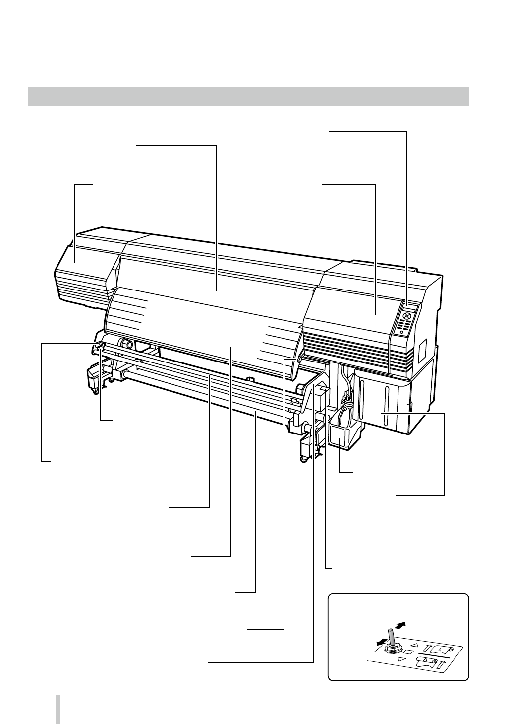
装置外観・各 部の名称と働き
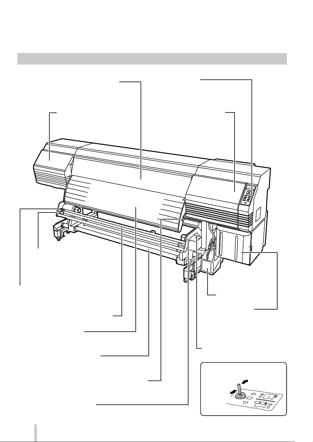
◆ 本機前面(排紙側)
印刷 するときは 必ず閉じて
お き ま す。
プ リント ヘッド のメ ン テ ナ ン ス を 行
う際に開けます。
メディアをカットした後、 メディア
が 落 下しな いように 止 め ま す。
プリンターの状態を表示するランプや
LCD、各 種機能を設定するキーが割り
付 け ら れて いま す。
キャッピングユニットの清 掃やワイ
パーブレードの交換をする時などに
開けます。
メディ ア をカ ットしま す。
インクを乾 燥させるアフターヒーターが内蔵されています。
印刷したメディアを巻き取ります。
メディアを固定また は 解 除するレバ ーです。
たる み 巻 き の と き にメデ ィ ア をガ イド し ま す。
2
カバーを開けてインクカートリッジを
セットしま す。
メディアを巻き取る方向を設定します。
巻き取りオフ
外巻き
外巻き
内巻き
Page 4
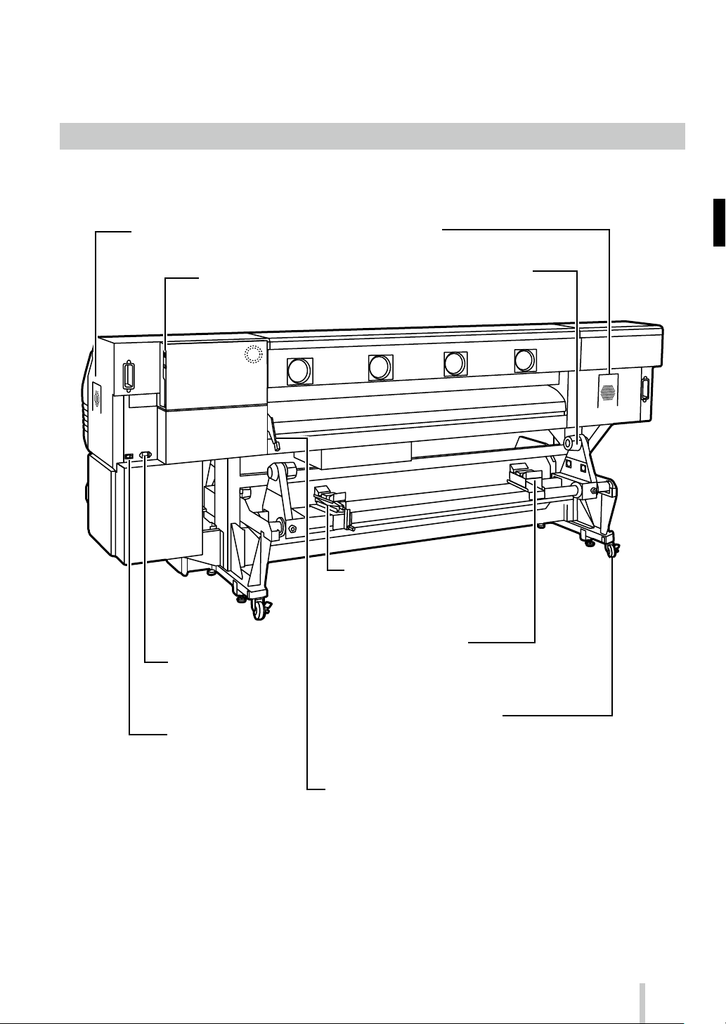
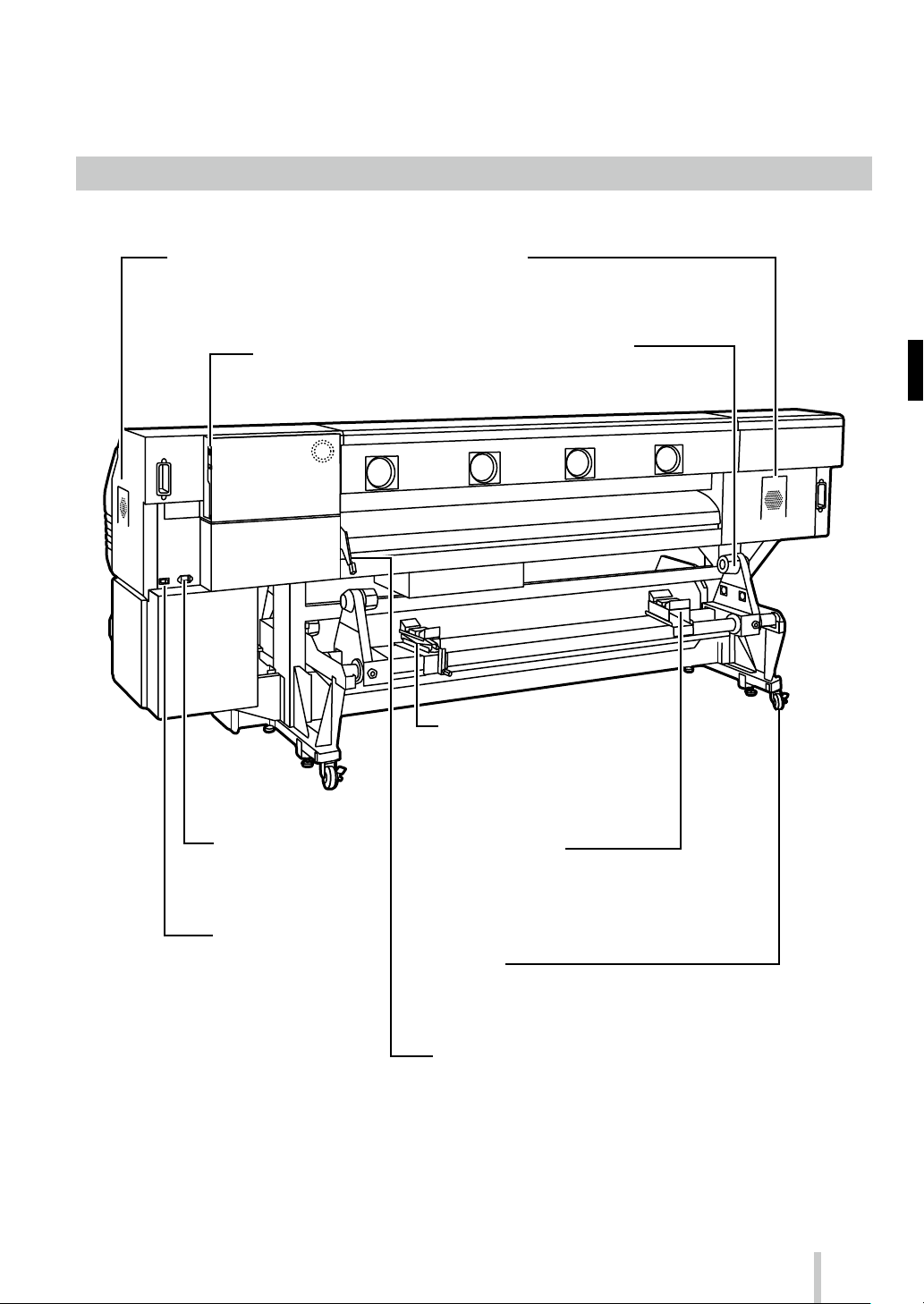
◆ 本機背面(給紙側)
コンピューターと接続します。
電 源コ ード を 接 続しま す。
ロールメディ アの両 端に 取り
付けます。
メディアの 脱 着 作 業 を 補 助 し ま す。
巻 き 取 り 装 置 側に 移 動して使 うこ
ともで きま す。
脱 着 時 に メディア を 一 時 的に 支 え ます。
巻 き 取り装 置 側に 移 動して使 う こ と もで き ま す。
プリンターを移 動 するときは ロックを OFF に
し、 固 定 す る と き は ロ ック を O N に し ま す。
メディアを固定また は 解 除するレバ ーです。
プ リン タ ー 前 面 の 加 圧 ロ ー ラ ーア ッ プ ダ ウ ンレ
バ ー と 同 期 して 動き ま す。
3
Page 5
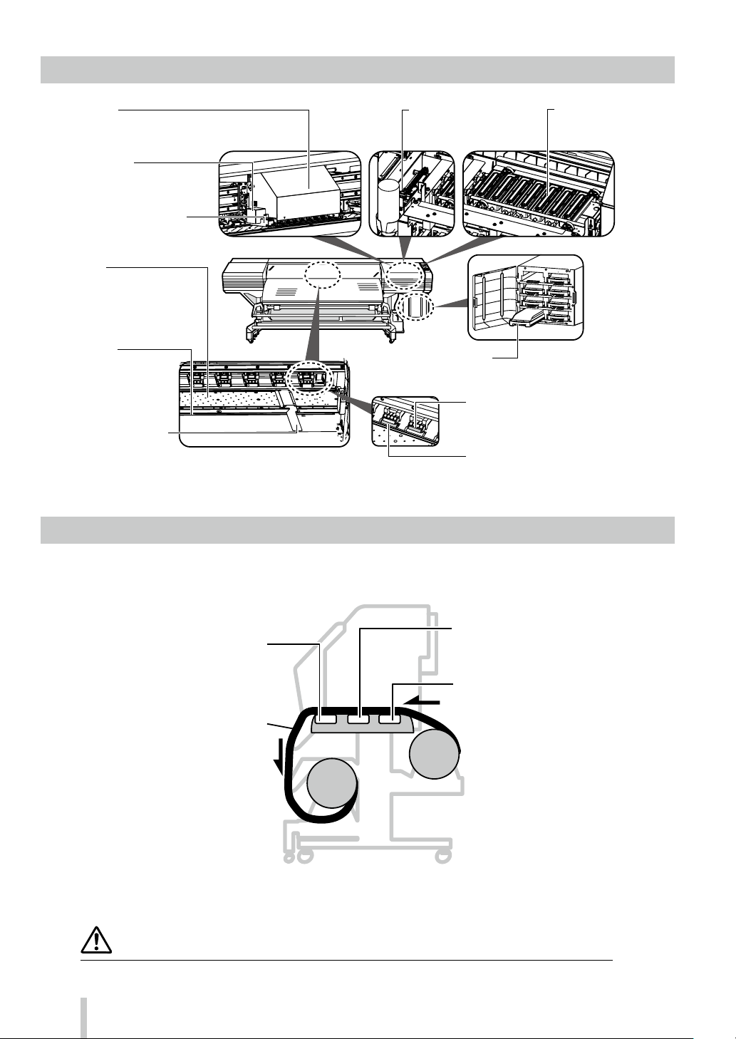
◆ 本機内部
プリントヒーター(前面)
メディア に インクを 浸 透 さ せ 、
アフターヒーター(仕 上げ)
インクを乾燥し、画質を安定させます。
■キャリッジ
プリ
印刷時
■
メデ
ス
■
自
です
■
メデ
やケバか
護し
■
この
挿入
ガイ
とが
■
メデ
かな
を定
さ
■ワイピングユニット
■キャッピングユニット
ントヘッドが 格納されているユニットで、
メディア を走査し て印刷します 。
イオナイザー
ィアの静電気を中和し、イン クミ
トによる印刷汚れを軽減します。
自動印刷調整用センサー
動印刷調整に使用する光学センサー
。
プラテン
ィアの通り道です。メディア が浮
いようにする吸着ファンとインク
着させるプリントヒ ーターが内蔵
れています。
カッター溝
溝にカッターナイフの刃を
してメディア を切ると 刃が
ドされてまっすぐに切るこ
できます。
メディア エッジガード
ィア 両端(エッジ )のカール
らプリントヘッドを保
ます。
◆ ヒーター
プリントヘッドのノズ ル面の
異物を取り除きます。
プリントヘッドのノズ ルが乾く
のを防ぎます。
■インクトレイ
インクカートリッジをセットするためのトレ イです。
■グリットロ ーラー
メディア を送り出したり、戻したり
するローラーです。
■加圧ローラー
加圧ローラーアップダウンレバーを下げると
メディア を挟み込みます。
本機には、印刷メディアへのインクの定着・画質の安定化のために3つのヒーターを搭載しています。
* 3 つのヒーターは各 々 独立にコントロールされます。
ヒーター温度は操作パネル、ソフト RIP および CP_Mana ger からコントロールできます。
警告
◆◆ 各ヒーター面は熱くなりますので、決して触らないでください。火傷をするおそれがあります。
4
メディア
インクを 定 着させ ま す 。
プリヒーター(背面)
メディア を 予 熱し ま す 。
Page 6
◆ 操作パネル
MENU
ADJUST
MAINTENANCE
NOZZLE PRINT
PH.RECOVERY
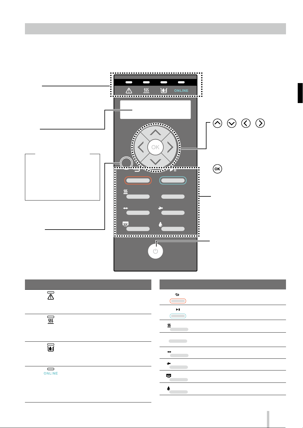
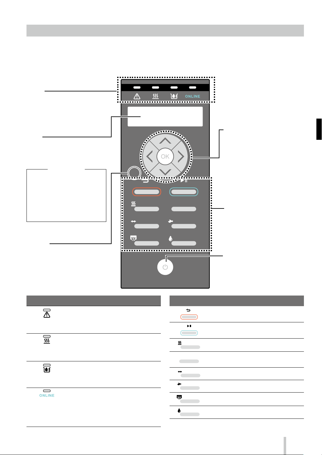
本機の操作パネルには、キー,LED,LCD が下図のようにレイアウトされています。なお、エラー時や無効キー
入力時には、ブザーで通知する機能もついています。
また、一定時間装置を使用しない場 合、ウェイティングモードに遷移します。
点灯、点滅、消灯によって本機の状
態 を 表 示しま す。
下 表 を 参 照してく だ さ い 。
プリンターの 状 態やメニュー 画 面な
ど を 表 示 し ま す 。( 2 0 文 字 2 行 )
( ウェイティングモ ード の状 態 )
LCD:表示および、バックライト O FF
オンライン LED:ゆっくり点滅
オンライン LED 以外:消灯
( ウェイティングモ ード の 解 除 )
いずれかのキーを操作した場合。
印刷データを受信した場 合。
エラー発生時、無効キー入力の警告、
およ び日常メンテナンスなどプリン
ト ヘッド が キャ ッ プ され て い な い 状
態 の 警 告 時 に 鳴 動しま す。
エラ ー の 有/無 を 表 示し ま す。
・ 点 灯 : エ ラ ー あ り
・ 点 滅 : ワ ー ニ ン グ あ り
・ 消 灯 : 正 常( エ ラ ー な し )
メディ ア ヒー ター の 状 態 を 表 示 し ま す。
・点灯: メディアヒーター設定温度に到達
・ 点 滅 : メ デ ィ ア ヒ ー タ ー 昇 温 中
・ 消 灯: メ デ ィ ア ヒ ー タ ー O F F
イン ク の 有 / 無 を 表 示 しま す。
・点灯: すべてのインクあり
・ 点 滅 : イ ン ク の 残 量 が 少 な い
・ 消 灯: イ ン ク な し
プリンターのオンライン / オフライン/データ
受 信 / プ リ ント ポ ーズ 状 態 を 表 示しま す。
・ 点 灯 : オ ン ラ イ ン
・点滅(ゆっくり):プリントポーズ
・点滅(はやい):データ受 信
・消灯: オフライン
SET
ORIGIN
CANCEL
HEATER MENU
ADJUST
NOZZLE PRINT PH.RECOVERY
ONLINE
MAINTENANCE
POWER
CANCEL
ONLINE
HEATER
メニューグル ープの 選 択、メ
ニ ュ ー の 切 り 換 え( 選 択 、 数
値のアップ/ダウン)など に
使 用し ま す。
メニューの確定,パラメータの確定
に使 用しま す。
プリンターのメニュー 操作 などに使
用しま す。
下 表 を 参 照してく だ さ い 。
プリンターの電源をオン / オフする
電 源 スイッ チ と して 使 用し ま す。
手動でウェイティングモ ードに遷移さ
せる 場 合 やウェイティング モ ード を
解 除 す る 場 合 に使 用しま す。
入力した パラメーターをキャンセル、メニュー階層 を戻る
ときに使 用します。
プリンターのオンライン / オフラインの切り 替え、プリン
トポーズ/プリント再開 するとき に使 用します。
ヒーターコントロールメニューに入るときに使 用します。
プリンターの各 種 情 報表 示、各 種 設 定変 更 するとき に使
用し ま す。
調整 メニューに入るときに使 用します。
メンテナンスメニューに入るときに使 用します。
ノズルプリントを 印刷 するとき に使 用します。
クリーニングメニュー に入るときに使 用します。
5
Page 7

メディア の セット と 取 り 外 し
◆ 給 紙 装 置 へ のメデ ィア の セ ット
1
2
4
5
6
3
6
Page 8

7
11
8
9
10
12
13
14
15
SET
ORIGIN
CANCEL
HEATER MENU
ONLINE
7
Page 9
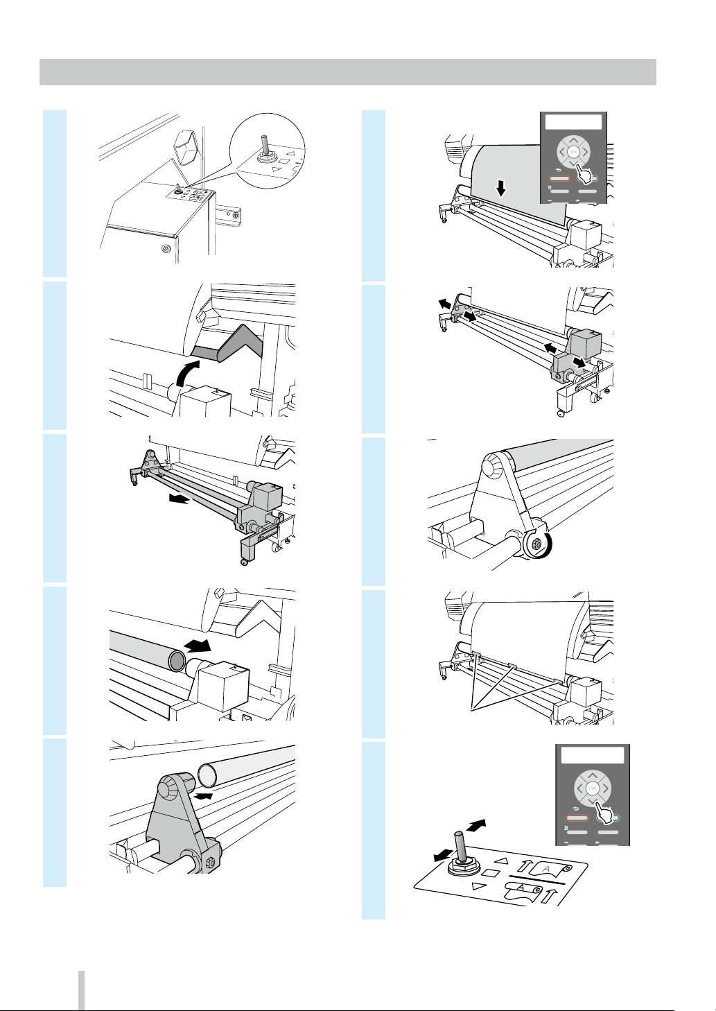
◆ 巻 き 取り 装 置 へ のメデ ィア の セット
ON
1
2
3
OFF
6
7
8
SET
ORIGIN
CANCEL
HEATER MENU
ADJUST
ONLINE
MAINTENANCE
8
4
5
9
10
テープ
SET
ORIGIN
CANCEL
HEATER MENU
ADJUST
ONLINE
MAINTENANCE
Page 10

11
OFF
(
12
15
13
14
SET
ORIGIN
CANCEL
HEATER MENU
ADJUST
ONLINE
MAINTENANCE
16
メディア送り
モード
対象メディア)
内巻き
ON
たるみ巻き巻き取り方式 テンション巻き テンション巻き
チュウ(推奨)吸着ファン ジャク(推奨) ジャク(必須)
ツウジョウ
ジャク
キョウ
シワケイゲン
(塩ビ、コート紙)
使用できません 使用できません
ツウジョウ
シワケイゲン
(ターポリン) (薄手ターポリン)
サイキョウ
外巻き
9
Page 11
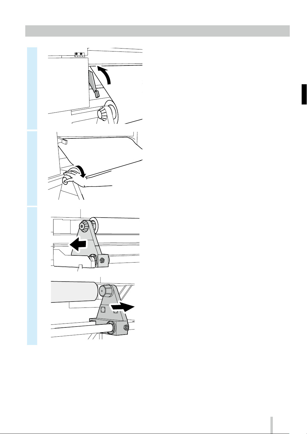
◆ 巻き取り装 置からのメディア取り外し
ON
1
2
3
②
OFF
①
5
6
7
①
②
4
①
②
10
Page 12
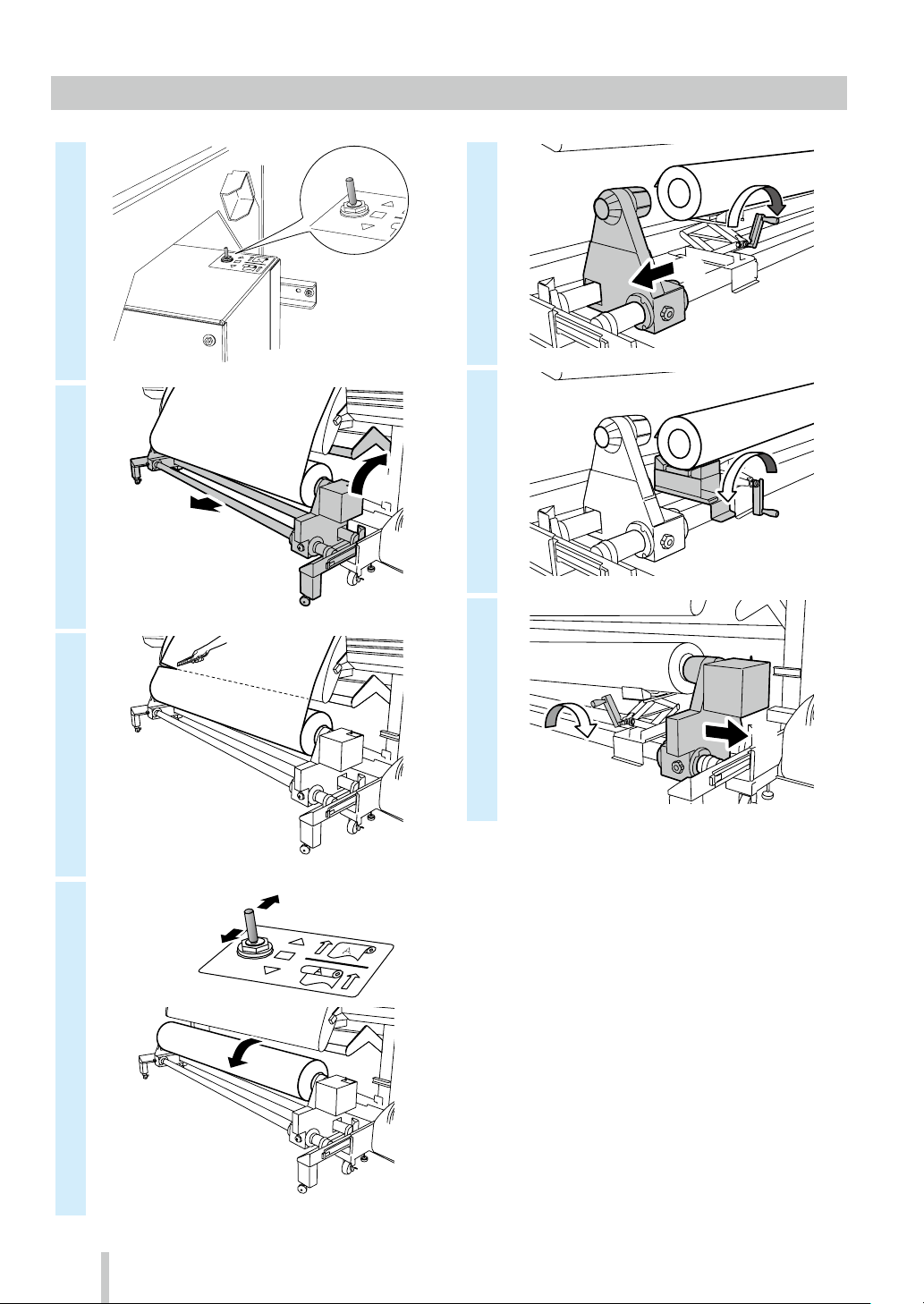
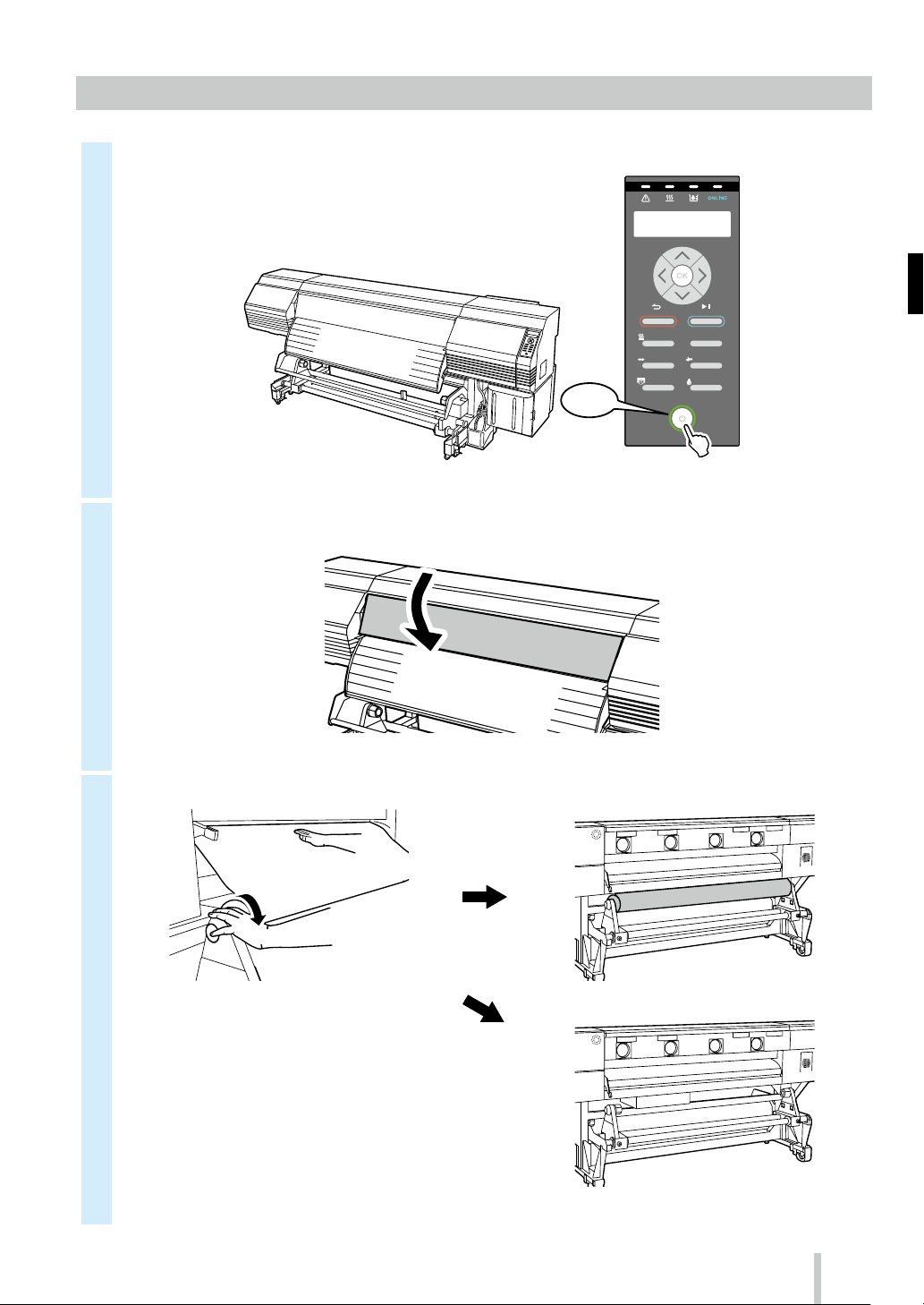
◆ 給 紙 装 置 からのメディア 取り外し
1
2
3
11
Page 13

調整をする
◆ 送り調整をする
1
2
3
4
フ°リントテ゛キマス
01:PAPER/1626mm
ADJUST
↕オクリチョウセイ ◎
>オクリチョウセイ
↕シ゛ト゛ウチョウセイ ◎
6
7
>> シ゛ト゛ウチョウセイ
インサツシ゛ッコウ OK?
12
5
>> シ゛ト゛ウチョウセイ
↕サイコウソク ◎
サイコウソク
コウソク
ソクド ユウ セン
ヒョウジュン
ガシ ツユウ セン
コウガシツ
サイコウ ガ シ ツ
さらに 細 かい調 整 を 行 う場 合は、「マニュアル 調整 」
を 行 ってく だ さ い 。
「マニュアル調整」の方法は、取扱説明書を参照し
てくだ さい 。
Page 14
◆ 往復調整をする
1
2
3
4
フ°リントテ゛キマス
01:PAPER/1626mm
ADJUST
↕オウフクチョウセイ ◎
>オウフクチョウセイ
↕シ゛ト゛ウチョウセイ ◎
6
>> シ゛ト゛ウチョウセイ
インサツシ゛ッコウ OK?
7
さらに 細 かい調 整 を 行 う場 合は、「マニュアル 調整 」
を 行 ってく だ さ い 。
「マニュアル調整」の方法は、取扱説明書を参照し
てくだ さい 。
5
>> シ゛ト゛ウチョウセイ
↕1:サイソク,コウソク,ソクト゛ユウ◎
スベテノ インサツモード
1: サイソク , コウソク ,
ソクド ユウ
2:ヒョウジュン ,
ガシツユウ
3:コウガシツ 高画質
4: サイコウガシツ 最高画質
全ての 印刷 モード
を調整します
最高速、高速、
速度優先
標準、画質優先
13
Page 15
メンテナンスをする
◆ ワイパーブレードの汚れチェック、キャッピングユニットの清掃、クリーニング(開 始前のメンテナンス)
1
2
3
4
フ°リントテ゛キマス
01:PAPER/1626mm
MAINTENANCE
↕カイシマエノメンテナンス ◎
>カイシマエノメンテナンス
OK?◎
7
OK NG
ワイパ ーブ レ ード に 汚 れ や き ず が 見 ら れ た 場
合は、「カイシマエノメンテナンス」終了後に、
「ワイパーブレードコウカン」を実施して、ワ
イパーブレードを交換してください。
8
14
IP7-2 64 クリーニング 棒(大)
※IP6-271 日常メンテナンスキット A にも
含 ま れ ま す。
5
6
マエショリチュウ
シハ゛ラクオマチクタ゛サイ 1:00
カハ゛ーヲアケテ キャッフ゜セイソウ
ワイフ゜カクニンヲ シテクタ゛サイ
IP6-272キャップクリーニング液 A
※IP6-271 日常メンテナンスキット A にも
含 ま れ ま す。
※一度キャップを清掃したクリーニング棒
(大 )をキャップクリーニング 液 ボトル の 中
に入れないでください。キャップクリーニ
ング 液 が 汚 れてしま い ま す。
※1 本のクリーニング 棒(大 )をキャップクリー
ニング液に1 回浸ければ、すべてのキャッ
ピ ングユ ニット を 清 掃 する こ とが で き ま す。
Page 16

9
13
クリーニンク゛ヲシ゛ッシシマスカ?
OK/CANCEL ◎
10
1. は じ め に 、各 キ ャップ上 面 の 外 周 部 分 を、
クリーニング棒( 大 )で 1 周させます。
これにより、各キャップ表面の汚れに
キャップクリーニング液を浸 透させます。
作業は、左のキャップから右方向に向
か って 行 い ま す。
2.次に、各キャップ上面の外周部分を、ク
リーニング棒(大)で 5 周させて、汚れ
を拭き取ります。
作業は、左のキャップから右方向に向
か って 行 い ま す。
キャッフ゜セイソウ ワイフ゜カクニンシテ
カハ゛ーヲシメテクタ゛サイ
14
15
16
クリーニンク゛スタート
ホ゛トルカクニンOK?
クリーニンク゛チュウ 1234567
ノコリシ゛カン Y:YY
NOZZLE PRINTヲ
シ゛ッシシテクタ゛サイ
MAINTENANCE
↕カイシマエノメンテナンス ◎
11
12
>キャッフ゜セイソウカンリョウ
OK? ◎
アトショリチュウ
シハ゛ラクオマチクタ゛サイ 1:00
15
Page 17

◆ ノズルプリント
例
が161番ノズル側に寄っている。
1
フ°リントテ゛キマス
01:PAPER/1626mm
2
NOZZLE PRINT
↕インサツシ゛ッコウOK?◎
3
4
5
NOZZLE PRINT
シ゛ッコウチュウ
ノズ ルプリント の印 刷 サン プ ル
線の抜けが発生している
NG
24番ノズルと133番ノズルが抜けている例 159番ノズルにインク吐出方向の曲がりがある
インク吐出方向の曲がり
が発生している
NG
6
7
8
9
フ゜リントテ゛キマス
01:PAPER/1626mm
ADJUST
↕ノス゛ルマッフ゜セッテイ ◎
>ノス゛ルマッフ゜セッテイ
◎
↕Lc
ノス゛ルマッフ゜セッテイ
>>
↕#1:***/カヘン ◎
Lc
159番ノズルで印刷した線(←の線)
※ノズルプリントで線の抜けや線の曲がりがある場
合には、「通常クリーニング」 を 実 施して、再度 1
の 手 順 か ら 繰 り 返 してく だ さ い 。
通常クリーニングは 、
と で 実 施 で き ま す。
それでも線の抜けや線の曲がりが直らない場合
は、6 以降の手順でそのノズル番号に対して「ノ
ズルマップ」 を設 定してください 。
※「ノズルマップ」の設定には、「マニュアル設定」
と「自動 設定 」 があります。
(自動設定の詳細は、取扱説明書( を
参 照 し て く だ さ い 。)
キーを押すこ
10
11
>>>Lc:#1
↕***/カヘン→133/カヘン ◎
>>>Lc:#1
↕133/カヘン→133/カヘン
※線の抜け、線の曲がりが複数ある場合はこ
の手 順を繰り返しすべ てのノズ ル番 号を 設
定してく ださ い 。
16
Page 18

◆ ワイパークリーニング 液のチェックと交換
終了 2以降の手順を実施
②
1
2
3
OK NG
フ°リントテ゛キマス
01:PAPER/1626mm
MAINTENANCE
↕ワイハ゜ーメンテナンス ◎
8
使 用済 み ワ イパー クリーニング 液
※ 手 袋 を 着 用して 作 業 を 行 ってく だ さ い 。
9
IP6-251ワイパークリーニング液セット A
※IP6-271 日常メンテナンスキット A にも
含 ま れ ま す。
プ リ ン タ ー セ ット 用 キ ャッ プ
新しいワイパークリーニング液
10
4
5
6
7
ワイハ゜ーメンテナンス
↕ワイハ゜ークリーニンク゛エキコウカン◎
11
> ワイハ゜ークリーニンク゛エキコウカン
OK?◎
ワイハ゜ークリーニンク゛エキヲ
コウカンコ゛カハ゛ーヲシメテクタ゛サイ
12
カハ゛ーヲアケテワイハ゜ークリーニンク゛
エキヲコウカンシテクタ゛サイ
①
②
13
コウカン シマシタカ?
↕YES ◎
※毎日のチェックのほか、プリンターの交換
メッセージが 表 示 されたときにもワイパー
クリーニング液を交 換してください。
①
17
Page 19
◆ ワイパーブレ ードの 汚れチェックと交 換
終了 2以降の手順を実施
1
OK NG
2
3
フ°リントテ゛キマス
01:PAPER/1626mm
MAINTENANCE
↕ワイハ゜ーメンテナンス ◎
8
①
②
9
10
4
5
6
7
> ワイハ゜ーメンテナンス
↕ワイハ゜ーフ゛レート゛コウカン ◎
>> ワイハ゜ーフ゛レート゛コウカン
OK?◎
キャリッシ゛イト゛ウチュウ
シハ゛ラクオマチクタ゛サイ
カハ゛ーヲアケテワイハ゜ーフ゛レート゛ヲ
コウカンシテクタ゛サイ
18
Page 20

11
③ スポンジ
平行になっていること
②
①
②
② ゴム
左右の隙間が均等であること
① ゴム
14
コウカン シマシタカ?
↕YES ◎
※毎日のチェックのほか、プリンターの交換
メッセージが 表 示 されたときにもワイパー
ブレードを交換してください。
12
13
ツメが中心にあること
ツメ
左右ともここに当たっていること
IP6-259ワイパーブレード
※取りつける順番を間違えないでください。
※IP6-271 日常メンテナンスキット A にも
含 ま れ ま す。
ワイハ゜ーフ゛レート゛ヲコウカンコ゛
カハ゛ーヲシメテクタ゛サイ
①
19
Page 21

◆ 廃 インクボトルの チェックと交 換
実施
1
OK NG
FULL
終了 2以降の手順を
2
4
5
FULL
IP6-109廃インクボトル
3
6
7
ハイインクカウンターリセット
↕YES ◎
※毎日のチェックのほか、プリンターの交換
メッセージが 表 示 されたときにも廃インク
ボトルを交換してください。
20
Page 22
◆ そ の他 のメンテナンス
ド
加圧ローラー
ペーパー
フロントカバー
そのほか、プリンターの交換メッセージが表示された
ときに「ワイパースポンジ」を交換してください。
プリンターの汚れが目立つ場合には、以下の箇所を清
掃してく ださ い 。
<ヘッド ガード の 清 掃 >
キャリッジ
キャッピングユニットの汚れが目立つ場合は、「シート
マウントクリーニング」 を実 施してください。
<加 圧ローラー、プラテンの清掃>
ヘッドガー
プラテン
<外装(フロントカバー)、ペーパーガイドの清掃>
<メディアエッジ ガ ードの 清 掃>
ガイド
これらの詳細な方法については取扱説明書を参照して
ください。
21
Page 23
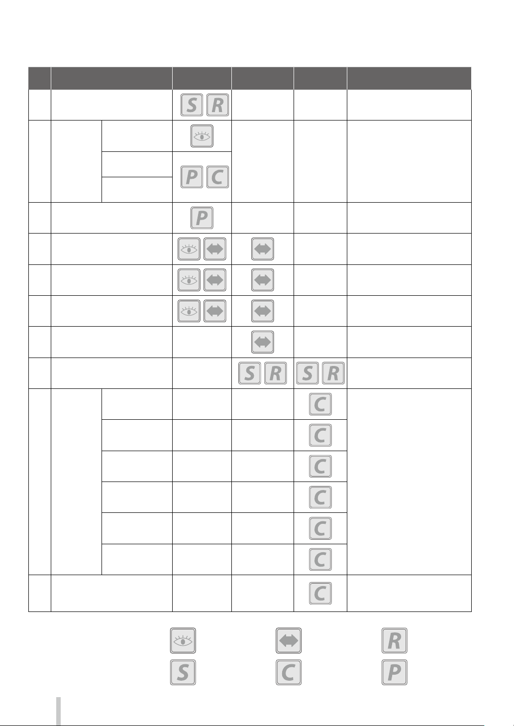
各種メンテナンスを行 う周 期は 以下の通りで す。
・・・パネル操作
メディ アセ ット
ワイパ ーブレ ード
の汚 れチェック
開始前のメ
ンテ ナンス
キャッピ ング
ユ ニ ット の 清 掃
クリーニング
ノズ ルプ リント
廃 インクボトル の チェックと
交換
ワイパー クリーニング液の
チェックと交 換
ワイパ ーブレ ードの 汚 れ チェッ ク
と交換
ワ イパース ポン ジ 交 換
IP6-272
キャップクリーニング 液 A
IP 7- 264
クリーニング 棒(大)
※1
※1
IP6-109廃インクボトル
IP6 -251
ワイパー クリーニング液 セット A
IP6-259ワイパーブレード
IP6-258ワイパースポンジ
※1
※1
シートマウントクリーニング
( 実 施 の目 安 は 1 ヶ月に 1 度 で す )
メディアエッジ
ガード清 掃
ヘッド ガード
清掃
プリンター
の清掃
(実 施の目安
は 1 週間に 1
度です)
プラ テン 清 掃
ペーパーガイド
清掃
加圧ローラー
清掃
外 装( フ ロ ン ト カ
バー) 清 掃
自動印刷 調整用のセンサーと
イオナイザー 周りの 清掃
(実 施の目安 は 1 年に 1 度で す)
※ 1 これらは、IP6-271日常メンテナンスキット A にも含まれます。
・・・確認
・・・交換
IP6-261
シートマウントクリーニングキット A
IP6 -147 クリーニング棒
IP6-272
キャップクリーニング 液 A
IP6 -147
クリーニング 棒
※1
※1
※1
・・・外す
22
・・・セット
・・・清掃
Page 24
◆ そ の日使い終わったら
1
2
ON
SET
ORIGIN
CANCEL
HEATER MENU
ADJUST
NOZZLE PRINT PH.RECOVERY
ONLINE
MAINTENANCE
POWER
3
23
Page 25

◆ インクカ ートリッジ の 交 換
爪2ヶ所を押す
②
新しいインクカートリッジ
1
2
※インク色と装着位置を間違えないでくださ
い。
5
I P 6 - 2 21 イエロ ー
IP6-222 マゼンタ
I P 6 - 2 2 5 ラ イトシ アン
IP 6 -223 シアン
IP 6 -224 ブラック
I P 6 - 2 2 6 ラ イトマゼ ンタ
IP 6 -227 グレー
6
②
①
3
4
使用済みインクカートリッジ
①
7
8
24
Page 26

IP-6620
Table of Contents
Appearance and main components
Cartridge ink system (CIS) ............................. 26
Printer front (take-up side) ............................................. 26
Printer rear (supply side) ................................................. 27
Printer interior ....................................................................28
Printer heater unit ............................................................. 28
Operation panel ................................................................. 29
Appearance and main components
Large capacity ink system (LCIS) ..................30
Printer front (take-up side) ............................................. 30
Printer rear (supply side) ................................................. 31
Printer interior ....................................................................32
Printer heater unit ............................................................. 32
Operation panel ................................................................. 33
Media installation and removal ................... 34
Loading the media on the feeding unit .................... 34
Installing the media on the TUR unit ......................... 36
Removing the media from the TUR unit ................... 38
Removing the media from the feeding unit ........... 39
Quick Reference Guide
ENGLISH
Adjustment ...................................................... 40
Adjusting the media advance ......................................40
Adjusting the bidirectional position .......................... 41
Maintenance .................................................... 42
Start maintenance (wiper blades check,
capping unit cleaning, cleaning) .................................. 42
Nozzle print ......................................................................... 44
Wiper cleaning liquid check and supply ................... 45
Wiper blade cleanliness check and replacement .. 46
Waste ink bottle check and replacement ................. 48
Other maintenance operations .................................... 49
After the operation of the day ...................................... 51
Ink cartridge replacement (CIS)..................................... 52
Ink bottle replacement (LCIS) ........................................ 53
Reading the ink amount extension chip (LCIS) ....... 55
25
Page 27
Appearance and main components
Printer front (take-up side)
•
Operation panel
•
Front cover
Must be closed during printing.
Equipped with LEDs and LCD to display
the printer status, and buttons to set
functions.
Cartridge ink system (CIS)
•
Maintenance area cover
Open to perform print head
maintenance.
•
Media clip (option)
After cutting the media,
clip it to not let it fall.
•
Media cutter blade (option)
It cuts the media.
•
Capping unit cover
Opened when cleaning the capping
unit or the carriage.
•
Waste ink bottle
26
•
Cutter unit (64) (option)
•
Output paper guide
Contains the afterheater that dries ink.
•
Take-up reel unit
Winds the printed media.
•
Pressure roller lever
This lever fixes or releases the media.
•
Guide bar
Guides the media in loose mode.
•
Ink box
Open the cover to install
the ink cartridges.
•
Take-up direction switch
Sets the media take-up direction.
Winding o
Outer take-up
Inner take-up
Page 28
Printer rear (supply side)
•
Position to install optional exhaust attachment
•
USB connector
Used to connect the printer to a
computer.
•
Media holder
To be installed at both ends of
the roll media.
•
Power inlet
Connect the power cable to
the power inlet.
•
Printer power switch
•
Media jack
Lifts or lowers the media during
loading and removal procedures.
Can be used also when moved to the
TUR unit side.
•
Media support
Temporarily supports the media during
loading and removal procedures.
Can be used also when moved to the
TUR unit side.
•
Caster
Set the lock to OFF when moving the printer and set the
lock to ON when locking the printer.
•
Pressure roller lever
A lever used to fixe or release the media.
Moves together with the pressure roller lever at the
printer front side.
27
Page 29

Printer interior
Penetrates ink into media to fuse the ink.
• Afterheater (nishing)
Dries ink to stabilize print quality.
• Ionizer
R
and reduces print def
•
Optical sensors used f
adjustment.
• Carriage
Houses the print heads inside
image with scanning media.
• Media edge guar
Pr
being damaged by the curling
or
• C
T
into this groove when cutting
the media so that it is cut
straight.
• Platen
T
T
and print heater to cure the ink
• Wiping unit
• Capping unit
, and prints
emoves static electricity from the media
ects caused by ink mist.
Sensors for automatic print adjustment
or automatic print
ransports media.
he platen incorporates suction fans
.
utter groove
he cutter blade is inserted
d
otects print heads from
feathering media edge.
Printer heater unit
Removes foreign substances on
the print head’s nozzle surface.
• Ink tray
Supports ink cartridge setting.
• Grit roller
The grit roller advances or rewinds
the media.
• Pressure roller
When lowering the pressure roller
up/down lever, it pinches the media.
Prevents the print head’s
nozzles from drying.
The printer is equipped with three heaters for ink fusing and image quality stabilization.
• Print heater (front)
28
* These three heaters are controlled independently.
The temperature of the heaters can be controlled from the operation panel, the RIP software and CP_
Manager.
WARNING
Do not touch these heaters to avoid burn as they become hot.
Media
• Preheater (rear)
Preheats media.
Page 30
Operation panel
MENU
ADJUST
MAINTENANCE
NOZZLE PRINT
PH.RECOVERY
The buttons, LEDs and LCD are placed on the printer's operation panel as shown below. In addition, the operation
panel is also equipped with a buzzer to draw attention in case an error occurs or an invalid button is pressed.
The printer enters waiting mode if it is not used for a given length of time.
•
LED
ON, blinking and OFF indicate the
status of the printer.
Refer to the table below.
•
Up, Down, Left, Right buttons
•
LCD
It shows the status of the printer and
displays the menu window (2 rows, 20
characters).
Waiting mode
(During waiting mode)
LCD: Display and backlight turned o
Online LED: Flashes slowly
Other LEDs: O
(Exiting waiting mode)
The printer exits waiting mode when
- any button is pressed,
- the printer receives print data.
•
Buzzer
Sounds when an error occurs or an
invalid button is pressed, and warns of
daily maintenance and when the print
heads are uncapped.
SET
ORIGIN
CANCEL
HEATER MENU
ADJUST
NOZZLE PRINT PH.RECOVERY
ONLINE
MAINTENANCE
POWER
Used to select menu options, switch
between menus (selection, increasing/
decreasing values), etc.
•
OK button
Used to confirm the menu and
parameters.
•
Buttons
Use these buttons to operate the menu
of the printer.
Refer to the table below.
•
Power switch
Used to turn on or off the power of the
printer.
Used to manually enter and exit waiting
mode.
Error LED
(Orange)
Media heater LED
(Green)
Ink LED (Green)
ONLINE LED
(Green)
LED
Indicates whether an error has occurred.
ON: An error has occurred.
Blink: Warning state.
OFF: Normal (no error)
Indicates the status of the media heater.
- ON: The set temperature has been reached
- Blink: Currently heating
- OFF: Media heater is o
Indicates whether ink is remaining.
ON: Ink of all colors is present.
Blink: Ink near-end ( The level of any color is low.)
OFF: No ink .
Indicates the online, oine, data reception, and
pause status.
- ON: Online
- Blink (slowly): In pause
- Blink (fast): Data reception
- OFF: Oine
CANCEL
ONLINE
HEATER
Buttons
Cancels entered parameters or returns back to the
upper menu.
Switches between online and oine states, and
puts the printer in pause or resumes printing.
Enters heater control menu.
Used to display information about the printer and
change printer settings.
Used to enter the adjustment menu.
Used to enter the maintenance menu.
Used to per form a nozzle print.
Used to enter the cleaning menu.
29
Page 31

Appearance and main components
Printer front (take-up side)
•
Operation panel
•
Front cover
Must be closed during printing.
Equipped with LEDs and LCD to display
the printer status, and buttons to set
functions.
Large capacity ink system (LCIS)
•
Maintenance area cover
Open to perform print head
maintenance.
•
Media clip (option)
After cutting the media,
clip it to not let it fall.
•
Media cutter blade (option)
It cuts the media.
•
Capping unit cover
Opened when cleaning the capping
unit or the carriage.
•
Waste ink bottle
30
•
Cutter unit (64) (option)
•
Output paper guide
Contains the afterheater that dries ink.
•
Take-up reel unit
Winds the printed media.
•
Pressure roller lever
This lever fixes or releases the media.
•
Guide bar
Guides the media in loose mode.
•
LCIS unit
Open the drawer to install the ink
bottles.
•
Chip reader
To be used with the ink amount extension chip.
•
Take-up direction switch
Sets the media take-up direction.
Winding o
Outer take-up
Inner take-up
Page 32

Printer rear (supply side)
•
Position to install optional exhaust attachment
•
USB connector
Used to connect the printer to a
computer.
•
Lifts or lowers the media during
loading and removal procedures.
Can be used also when moved to
the TUR unit side.
Media jack
To be installed at both ends of
the roll media.
•
Media holder
•
Power inlet
Connect the power cable to
the power inlet.
•
Printer power switch
•
Media support
Temporarily supports the media during
loading and removal procedures.
Can be used also when moved to the
TUR unit side.
•
Caster
Set the lock to OFF when moving the printer and set the
lock to ON when locking the printer.
•
Pressure roller lever
A lever used to fixe or release the media.
Moves together with the pressure roller lever at the
printer front side.
31
Page 33

Printer interior
Penetrates ink into media to fuse the ink.
• Afterheater (nishing)
Dries ink to stabilize print quality.
• Carriage
Houses the print heads inside
prints image with scanning media.
• Media edge guar
Pr
being damaged by the curling
or
• C
T
into this groove when cutting
the media so that it is cut
straight.
• Platen
T
T
and print heater to cure the ink
• Wiping unit
• Capping unit
• Ionizer
R
and reduces print def
•
Optical sensors used f
adjustment.
, and
emoves static electricity from the media
ects caused by ink mist.
Sensors for automatic print adjustment
or automatic print
ransports media.
he platen incorporates suction fans
.
utter groove
he cutter blade is inserted
d
otects print heads from
feathering media edge.
Printer heater unit
Removes foreign substances on
the print head’s nozzle surface.
• Ink bottle
Used to supply ink.
• Grit roller
The grit roller advances or rewinds
the media.
• Pressure roller
When lowering the pressure roller
up/down lever, it pinches the media.
Prevents the print head’s
nozzles from drying.
The printer is equipped with three heaters for ink fusing and image quality stabilization.
• Print heater (front)
32
* These three heaters are controlled independently.
The temperature of the heaters can be controlled from the operation panel, the RIP software and CP_
Manager.
WARNING
Do not touch these heaters to avoid burn as they become hot.
Media
• Preheater (rear)
Preheats media.
Page 34

Operation panel
MENU
ADJUST
MAINTENANCE
NOZZLE PRINT
PH.RECOVERY
The buttons, LEDs and LCD are placed on the printer's operation panel as shown below. In addition, the operation
panel is also equipped with a buzzer to draw attention in case an error occurs or an invalid button is pressed.
The printer enters waiting mode if it is not used for a given length of time.
•
LED
ON, blinking and OFF indicate the
status of the printer.
Refer to the table below.
•
Up, Down, Left, Right buttons
•
LCD
It shows the status of the printer and
displays the menu window (2 rows, 20
characters).
Waiting mode
(During waiting mode)
LCD: Display and backlight turned o
Online LED: Flashes slowly
Other LEDs: O
(Exiting waiting mode)
The printer exits waiting mode when
- any button is pressed,
- the printer receives print data.
•
Buzzer
Sounds when an error occurs or an
invalid button is pressed, and warns of
daily maintenance and when the print
heads are uncapped.
SET
ORIGIN
CANCEL
HEATER MENU
ADJUST
NOZZLE PRINT PH.RECOVERY
ONLINE
MAINTENANCE
POWER
Used to select menu options, switch
between menus (selection, increasing/
decreasing values), etc.
•
OK button
Used to confirm the menu and
parameters.
•
Buttons
Use these buttons to operate the menu
of the printer.
Refer to the table below.
•
Power switch
Used to turn on or off the power of the
printer.
Used to manually enter and exit waiting
mode.
Error LED
(Orange)
Media heater LED
(Green)
Ink LED (Green)
ONLINE LED
(Green)
LED
Indicates whether an error has occurred.
ON: An error has occurred.
Blink: Warning state.
OFF: Normal (no error)
Indicates the status of the media heater.
- ON: The set temperature has been reached
- Blink: Currently heating
- OFF: Media heater is o
Indicates whether ink is remaining.
ON: Ink of all colors is present.
Blink: Ink near-end ( The level of any color is low.)
OFF: No ink .
Indicates the online, oine, data reception, and
pause status.
- ON: Online
- Blink (slowly): In pause
- Blink (fast): Data reception
- OFF: Oine
CANCEL
ONLINE
HEATER
Buttons
Cancels entered parameters or returns back to the
upper menu.
Switches between online and oine states, and
puts the printer in pause or resumes printing.
Enters heater control menu.
Used to display information about the printer and
change printer settings.
Used to enter the adjustment menu.
Used to enter the maintenance menu.
Used to per form a nozzle print.
Used to enter the cleaning menu.
33
Page 35

Media installation and removal
Loading the media on the feeding unit
1
2
4
5
34
3
6
Page 36

7
11
8
9
10
12
13
14
15
SET
ORIGIN
CANCEL
HEATER MENU
ONLINE
35
Page 37

Installing the media on the TUR unit
ON
1
2
3
OFF
6
7
8
SET
ORIGIN
CANCEL
HEATER MENU
ADJUST
ONLINE
MAINTENANCE
36
4
5
9
10
Adhesive tape
SET
ORIGIN
CANCEL
HEATER MENU
ADJUST
ONLINE
MAINTENANCE
Page 38

11
OFF
12
15
<In loose mode>
13
14
SET
ORIGIN
CANCEL
ONLINE
HEATER MENU
MAINTENANCE
ADJUST
<Inner take-up direction>
LOW
ON
LOW (required)
BACK & FWD MAX
16
LOOSETUR MODE TENSION TENSION
SUCTION FAN
POWER
MEDIA ADVANCE
MODE
Target media Banner Thin banner
Inner take-up
HIGH
(recommended)
FORWARD ONLY
BACK & FWD LOW
BACK & FWD HIGH
FWD LESS WRINKLES
Vinyl and coated paper
Cannot be used Cannot be used
(recommended)
FORWARD ONLY
FWD LESS WRINKLES
<Outer take-up direction>
Outer take-up
37
Page 39

Removing the media from the TUR unit
ON
1
2
3
②
OFF
①
5
6
7
①
②
4
①
②
38
Page 40

Removing the media from the feeding unit
1
2
3
39
Page 41

Adjustment
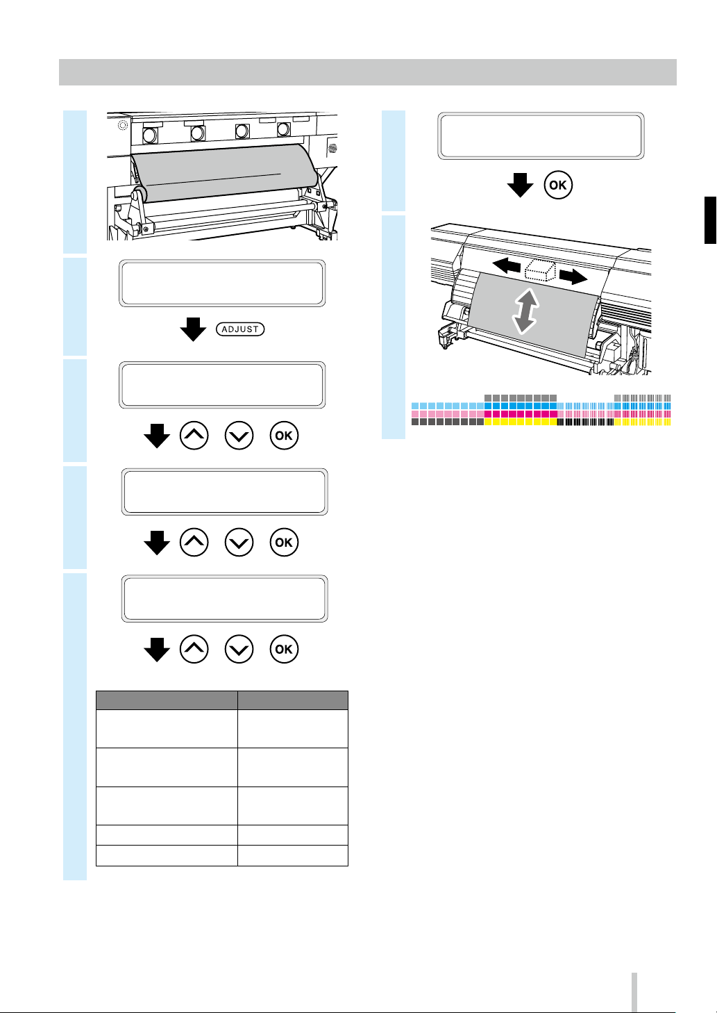
Adjusting the media advance
1
2
3
4
PRINTER READY
01: PAPER / 1626mm
ADJUST
MEDIA ADVANCE
2
, ,
>MEDIA ADVANCE
MEDIA ADVANCE AUTO
2
(LCIS)
Print mode
FAST PRODUCTION
PRODUCTION
STANDARD
QUALIT Y
HIGH QUALITY
MAX QUALITY
6
>>MEDIA ADVANCE AUTO
EXECUTE OK?
7
40
5
(CIS)
DRAFT
FAST PRODUCTION
PRODUCTION
STANDARD
QUALIT Y
HIGH QUALITY
MAX QUALITY
, ,
>>MEDIA ADVANCE AUTO
DRAFT
2
, ,
Print mode
To make finer adjustment, perform manual adjustment.
Refer to the User’s Guide for the manual adjustment
procedure.
Page 42

Adjusting the bidirectional position
1
2
3
4
PRINTER READY
01: PAPER / 1626mm
ADJUST
BIDIR POSITION
2
, ,
>BIDIR POSITION
MEDIA ADVANCE AUTO
2
(LCIS)
Bidirectional
adjustment pattern
ALL PRINT MODES All print modes
1: FAST PRO, PRO Fast production and
2: STD & QUALITY Standard and quality
3: HIGH QUALITY High quality
4: MAX QUALITY Max quality
6
>>MEDIA ADVANCE AUTO
EXECUTE OK?
Print mode
production
7
, ,
5
>>MEDIA ADVANCE AUTO
1: DRA,FAST PR,PRO
2
, ,
(CIS)
Bidirectional
adjustment pattern
ALL PRINT MODES All print modes
1: DRA,FAST PR,PRO Draft, fast production,
2: STD & QUALITY Standard and quality
3: HIGH QUALITY High quality
4: MAX QUALITY Max quality
Print mode
and production
To make finer adjustment, perform manual adjustment.
Refer to the User’s Guide for the manual adjustment
procedure.
41
Page 43

Maintenance
GOOD
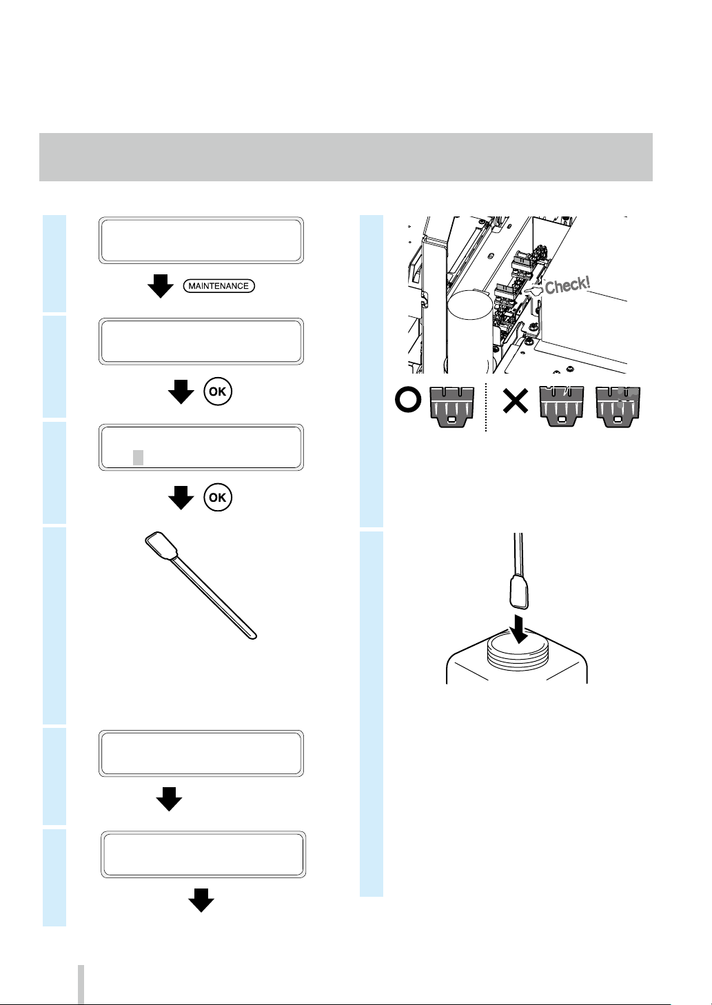
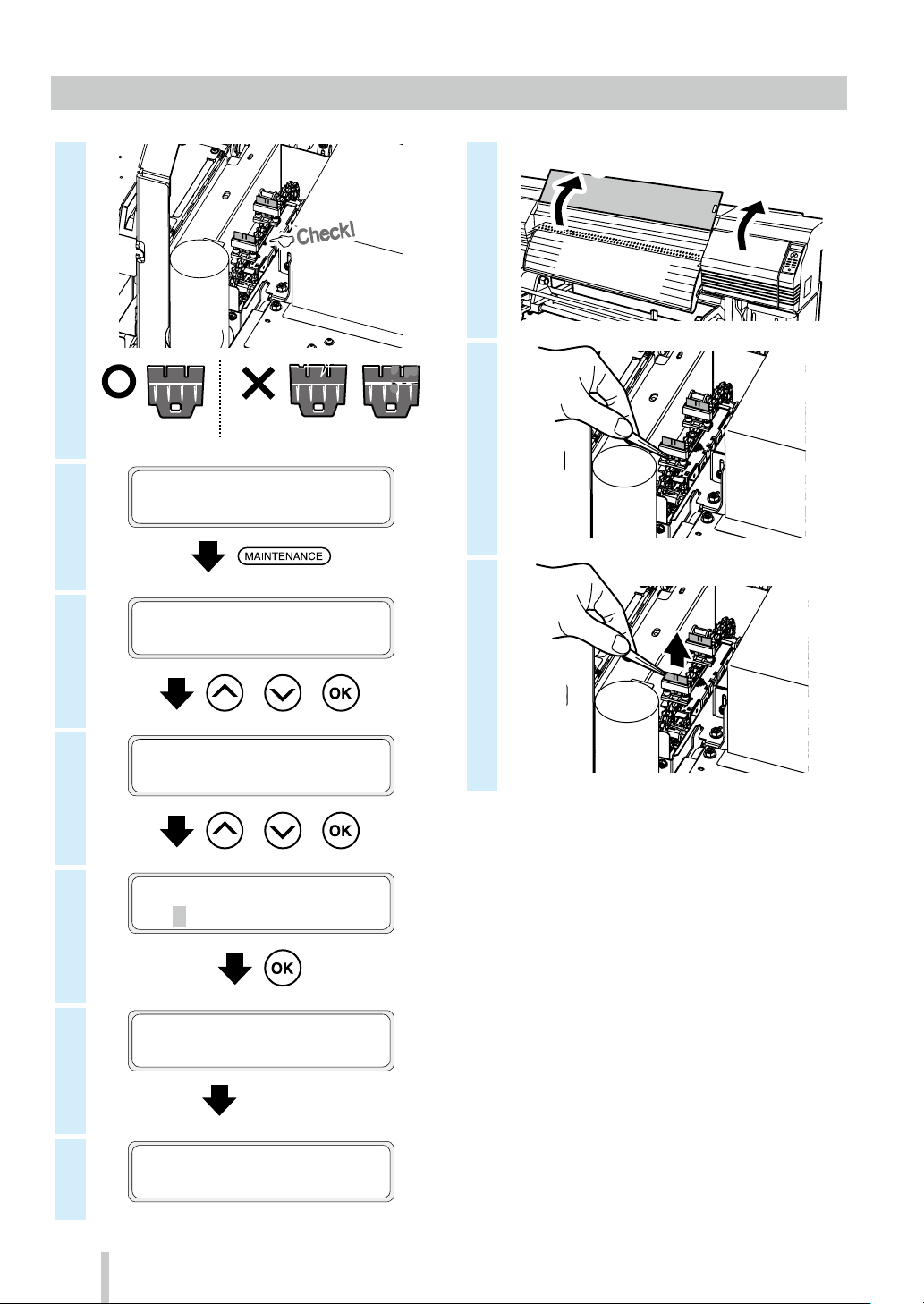
Start maintenance (wiper blades check, capping unit cleaning, cleaning)
1
2
3
PRINTER READY
01: PAPER / 1626mm
MAINTENANCE
START MAINTENANCE
2
>START MAINTENANCE
OK?
7
BAD
If you find that the wiper blades are damaged or
dirty, execute REPLACE WIPER BLADE to replace
the wiper blades after START MAINTENANCE has
finished.
4
IP7-264 Cleaning swab (Thick)
* IP6-264 is also included in the IP6-271 daily
maintenance kit A.
5
6
1ST WIPING OPERATION
PLEASE WAIT 1:00
Carriage stops moving.
OPEN COVERS, CLEAN
CAPS AND CHECK WIPER
8
IP6-272 Cap cleaning liquid A
* IP6-272 is also included in the IP6-271 daily
maintenance kit A.
* To keep the cap cleaning liquid clean, do
not soak the cleaning swab (thick) in the cap
cleaning liquid bottle again after you have
cleaned the caps with it.
* You can clean the entire capping unit with
one cleaning swab (thick) soaked once in cap
cleaning liquid.
42
Page 44

9
13
14
START PH RECOVERY?
OK/CANCEL
PH RECOVERING
BOTTLE IS EMPTY?
(1) First, pass the cleaning swab (thick) over the
entire circumference of each cap top surface
to impregnate the dirt on the surface with cap
cleaning liquid.
Pass the cleaning swab (thick) starting from the
leftmost cap and continue to the rightmost cap
in order.
(2) Next, clean all the dirt by passing the cleaning
swab (thick) 5 times over the circumference of
each cap top surface.
Start from the leftmost cap and continue to the
rightmost cap in order.
10
CLEAN CAPS, CHECK
WIPER & CLOSE COVERS
15
16
PH RECOVERING 1234567
REQUIRED TIME Y:YY
The cleaning is complete.
PERFORM NOZZLE PRINT
MAINTENANCE
START MAINTENANCE
2
11
12
CAP CLEAN COMPLETE?
OK?
2ND WIPING OPERATION
PLEASE WAIT 1:00
43
Page 45

Nozzle print
toward the line of nozzle 161.
1
2
3
4
5
PRINTER READY
01: PAPER / 1626mm
NOZZLE PRINT
PRINT?
2
NOZZLE PRINT
EXECUTING
Example of nozzle print pattern
Missing lines are found
BAD BAD
Example when lines for nozzles 24 and
133 are missing in the printout.
6
7
8
Ink is not ejected
straight
Example when the nozzle 159
does not eject ink straight.
9
PRINTER READY
01: PAPER / 1626mm
ADJUST
SET NOZZLE MAP
2
, ,
>SET NOZZLE MAP
Lc
2
, ,
>>SET NOZZLE MAP Lc
#01:***/VAL
2
, ,
The line printed by the nozzle 159
(shown with the arrow) is bent
* If lines are missing or bent lines are found on the the
nozzle print pattern, perform normal cleaning and
repeat the procedure starting from step 1.
Press the PH.RECOVERY button to perform normal
cleaning.
If the same problems occur even after normal
cleaning, set nozzle map for the defective nozzle
numbers following the procedure from step 6.
* Nozzle map can be set to manual configuration or
automatic configuration.
(Refer to the User’s Guide page 104 for details on
automatic configuration.)
10
11
>>>Lc:#1
VAL
2
***/
>>>Lc:#1
133/ VALg133/ VAL
2
* If several lines are missing or several bent lines
are found, repeat the procedure to set nozzle
map for all defective nozzles.
VAL
g
133/
, , , ,
44
Page 46

Wiper cleaning liquid check and supply
is nished.
procedure from step 2.
GOOD
New wiper cleaning liquid
(2)
1
2
3
BAD
The procedure
PRINTER READY
01: PAPER / 1626mm
MAINTENANCE
WIPER MAINTENANCE
2
, ,
Continue the
8
Used wiper cleaning liquid
* Wear gloves to perform this procedure.
9
IP6-251 Wiper cleaning liquid set A
* IP6-251 is also included in the IP6-271 daily
maintenance kit A.
Printer set cap
10
4
5
6
7
WIPER MAINTENANCE
REPLACE LIQUID
2
, ,
>REPLACE LIQUID
OK?
OPEN COVERS, REPLACE
WIPER CLEANG LIQUID
(1)
(2)
11
12
13
AFTER REPLACING WCL
CLOSE COVERS
REPLACED WCL?
YES
2
* In addition to daily checks, supply wiper
cleaning liquid also when the printer displays
a message that prompts you to do so.
GOODBAD
(1)
, ,
45
Page 47

Wiper blade cleanliness check and replacement
GOOD
1
7
OPEN COVERS AND
REPLACE WIPER BLADE
2
3
4
BAD
The procedure
is nished.
PRINTER READY
01: PAPER / 1626mm
MAINTENANCE
WIPER MAINTENANCE
2
>WIPER MAINTENANCE
REPLACE BLADE
2
Continue the procedure
from step 2.
, ,
8
(1)
(2)
9
10
46
5
6
, ,
>>REPLACE BLADE
OK?
CARRIAGE IS MOVING
PLEASE WAIT
Carriage stops moving.
Page 48

11
(3) Sponge
(1) Rubber
s
They are parallel
(2)
(1)
(2)
(2) Rubber
The spaces on the right and left are equal
14
REPLACED WIPE BLADE?
YES
2
, ,
* In addition to daily checks, replace the wiper
blades also when the printer displays a
message that prompts you to do so.
IP6-259 Wiper blade
* Be sure to install the blades in the right order.
* IP6-259 is also included in the IP6-271 daily
maintenance kit A.
12
13
The protrusion is in the center
Parts are in contact at both the right and left side
AFTER REPLACING WB
CLOSE COVERS
Protrusion
(1)
47
Page 49

Waste ink bottle check and replacement
ntinue the procedure
GOOD
1
2
FULL
The procedure
is nished.
Co
BAD
from step 2.
4
5
FULL
IP6-109 Waste ink bottle
3
6
7
RESET WST INK COUNT?
YES
2
, ,
* In addition to daily checks, replace the waste
ink bottle also when the printer displays a
message that prompts you to do so.
48
Page 50

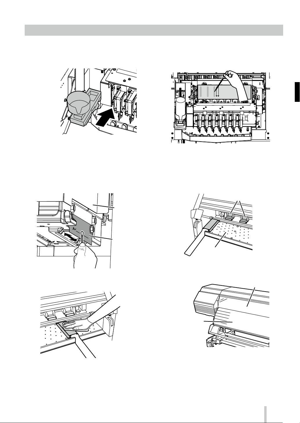
Other maintenance operations
Pressure roller
Replace also the wiper sponge when the printer displays
a message that prompts you to do so.
Clean the following parts when when you notice any dirt.
<Head guard cleaning>
Carriage
Perform sheet mount cleaning if you notice that the
capping unit is not clean.
<Pressure roller and platen cleaning>
<Media edge guards cleaning>
Head guard
Platen
<Front cover and paper guide cleaning>
Front cover
Output paper guide
See the User’s Guide for the cleaning procedures.
49
Page 51

The timing to perform each maintenance item is shown in the table below.
Panel operation
No. Item Daily
When a mess age is
displaye d
noticeably dirty
When it is
Consumables
A Media installation
Wiper blades
check
B Start maintenance
Capping unit
cleaning
Cleaning
C Nozzle print
Waste ink bottle check and
D
replacement
Wiper cleaning liquid check and
E
supply
Wiper blade cleanliness check and
F
replacement
G Wiper sponge replacement
Sheet mount cleaning
(This operation must be performed
H
approximately every month)
Media edge
guard cleaning
IP6-272 Cap cleaning liquid A *
IP7-264 Cleaning swab (Thick) *
1
1
IP6-109 Waste ink bottle
IP6-251 Wiper cleaning liquid set A *1
IP6-259 Wiper blade *1
IP6-258 Wiper sponge
IP6-261 Sheet mount cleaning kit A
Head guard
cleaning
Printer cleaning
(This operation
must be per formed
I
approximately once
per week)
Platen cleaning
Paper guide
cleaning
Pressure roller
cleaning
Front cover
cleaning
Cleaning around the ionizers and the
sensors for automatic print adjustment
J
(This operation must be performed
approximately once per year)
*1 Also included in the IP6-271 daily maintenance kit A.
• • •
• • •
Check
Set
• • •
• • •
Replace
Clean
IP6-147 Cleaning swab *1
IP6-272 Cap cleaning liquid A *
IP6-147 Cleaning swab *1
• • •
Remove
• • •
1
50
Page 52

After the operation of the day
Keep the printer turned on.
1
Keep the front cover closed.
2
ON
SET
ORIGIN
CANCEL
HEATER MENU
ADJUST
NOZZLE PRINT PH.RECOVERY
ONLINE
MAINTENANCE
POWER
Take up the media on the TUR unit, or remove the media from the printer.
3
51
Page 53

Ink cartridge replacement (CIS)
(2)
New ink cartridge
1
2
* Be sure to install the correct ink color in the
corresponding slot.
5
IP6-221 Y (yellow)
IP6-222 M (magenta)
IP6-223 C (cyan)
IP6-224 K (black)
IP6-225 Lc (light cyan)
IP6-226 Lm (light magenta)
IP6-227 Gy (gray)
6
(2)
(1)
3
4
Push two claws
7
8
Old ink cartridge
(1)
52
Page 54

Ink bottle replacement (LCIS)
1
2
PRINTER READY
01: PAPER / 1626mm
MENU
INFORMATION
2
7
3
4
5
6
>INFORMATION
WARNING INFO
2
,
>INFORMATION
INK INFORMATION
2
>>INK INFORMATION
BOTTLES TO SUPPLY
2
>>>BOTTLES TO SUPPLY
Lc*: Lm*: C*: Y*: K*: M*
* Number of ink bottles that can be supplied to
the reservoir
A hyphen “-” is displayed when the reservoir
drawer is open.
8
Lc
Lm
C
9
Turn slowly the B part in the counter-clockwise
direction while holding the A part with your hand
to prevent it from turning.
(2)
FULL
B
(1)
A
FULL
FULL
Y
K
M
53
Page 55

10
IP6-241 Y (yellow)
IP6-242 M (magenta)
IP6-243 C (cyan)
IP6-244 K (black)
IP6-245 Lc (light cyan)
IP6-246 Lm (light magenta)
11
12
13
(2)
(1)
FULL
FULL
FULL
54
Page 56

Reading the ink amount extension chip (LCIS)
1
2
3
4
PRINTER READY
01: PAPER / 1626mm
MENU
INFORMATION
2
MENU
INK AMT EXTENSION
2
>INK AMT EXTENSION
AVAILABLE INK
2
,
8
9
Open
Push
5
6
7
,
>INK AMT EXTENSION
READ EXT. CHIP
2
>>READ EXT. CHIP
OK?
INSERT EXT. CHIP
PRESS CANCEL TO QUIT
10
11
READING...
PLEASE WAIT
Close
Push
55
Page 57

12
OPERATION COMPLETED
X.XXL
X.XXL: Amount of ink that can be used
13
14
15
16
REMOVE THE
EXTENSION CHIP
Open
Close
Push
56
17
Push
INSERT EXT. CHIP
PRESS CANCEL TO QUIT
>INK AMT EXTENSION
READ EXT. CHIP
2
Page 58

IP-6620
Table des matières
Aspect et principaux composants
Système d’encre de la cartouche (CIS) ........58
Avant de l'imprimante (côté sortie papier) ................ 58
Arrière de l'imprimante (côté entrée papier) ............ 59
Intérieur de l'imprimante ................................................. 60
Unité de chauage de l'imprimante ............................ 60
Panneau de commande ................................................... 61
Aspect et principaux composants
Système d’encre à grande capacité (LCIS) ..62
Avant de l'imprimante (côté sortie papier) ................ 62
Arrière de l'imprimante (côté entrée papier) ............ 63
Intérieur de l'imprimante ................................................. 64
Unité de chauage de l'imprimante ............................ 64
Panneau de commande ................................................... 65
Installation et enlèvement de support ....... 66
Chargement du support dans l'unité d'alimentation
Chargement du support dans la bobine réceptrice
Retrait du support de la bobine réceptrice ............... 70
Retrait du support de l'unité d'alimentation ............ 71
.. 66
.. 68
Guide de référence rapide
FRANÇAIS
Réglage ............................................................. 72
Réglage de l'avance du support ................................... 72
Réglage de la position bidirectionnelle ..................... 73
Maintenance ....................................................74
Maintenance au démarrage (contrôle de la
lame de l’essuyeur, nettoyage de l’unité de
protection, nettoyage) .................................. 74
Impression avec les buses ................................................ 76
Alimentation et vérication du liquide de nettoyage
Vérication de la propreté et remplacement de
l'essuyeur ................................................................................ 78
Vérication et remplacement de la bouteille
de résidus d'encre ............................................................... 80
Autres opérations de maintenance .............................. 81
Après le fonctionnement quotidien ............................ 83
Remplacement de cartouche d'encre (CIS) ................ 84
Remplacement de la bouteille d'encre (LCIS) ............ 85
Lecture de la puce d’extension du niveau
d’encre (LCIS) ......................................................................... 87
.. 77
57
Page 59

Aspect et principaux composants
Avant de l'imprimante (côté sortie papier)
•
Panneau de commande
Équipé de voyants DEL et d'un écran LCD
•
Capot avant
Doit être fermé durant l'impression.
•
Capot de la zone de maintenance
Ouvrez-le pour procéder à la maintenance
de la tête d'impression
permettant d'acher l'état de l'imprimante
ainsi que des boutons permettant de
dénir les fonctions.
•
Capot de l’unité de protection
Ouvert lors du nettoyage de l'unité de
protection ou du chariot.
Système d’encre de la cartouche (CIS)
58
•
Clip de support (option)
Après avoir coupé le support, fixez-le
de façon à ce qu’il ne tombe pas.
•
Lame de massicot du support (option)
Elle sert à couper le support.
•
Unité de massicot (64) (option)
•
Guide-papier avant
Comprend le post-chauage permettant
de sécher l'encre.
•
Bobine réceptrice
Enroule le support imprimé.
•
Levier du rouleau presseur
Ce levier sert à xer ou à libérer le support.
•
Barre de guidage
Guide le support en mode feuillet par feuillet.
•
Boîte d'encre
Ouvrez le capot pour installer
les cartouches d'encre.
•
Bouteille de résidus d'encre
•
Commutateur de sens de sortie
Dénit le sens de sortie du support.
Enroulement
désactivé
Chargement vers
l’extérieur
Chargement vers
l’intérieur
Page 60

Arrière de l'imprimante (côté entrée papier)
•
Positions d’installation de l’accessoire d’échappement
•
Connecteur USB
Utilisé pour raccorder l'imprimante à un
ordinateur.
•
Porte-support
Il doit être installé aux deux
bouts du support en rouleau.
•
Prise d'entrée
d'alimentation
Raccordez le câble
d'alimentation à la prise
d'entrée d'alimentation.
•
Commutateur
d'alimentation de
l'imprimante
•
Guide de support
Soulève ou abaisse le support durant
les procédures de chargement et
d’enlèvement.
Peut également être utilisé lorsqu’il
est déplacé sur le côté de la bobine
réceptrice.
•
Soutien du support
Maintient temporairement le support durant les
procédures de chargement et d’enlèvement.
Peut également être utilisé lorsqu’il est déplacé sur le
côté de la bobine réceptrice.
•
Roulette
Placez le verrou sur OFF pour déplacer l'imprimante et sur
ON pour la bloquer en place.
•
Levier du rouleau presseur
Un levier utilisé pour xer ou libérer le support.
Se déplace avec le levier du rouleau presseur sur
l'avant de l'imprimante.
59
Page 61

Intérieur de l'imprimante
• Unité de chauffage de l'imprimante (avant)
• Unité de post-chauffage (nition)
Sèche l'encre de manière à stabiliser
la qualité d'impression.
• Ionisateur
Élimine l’
défauts d’
•
Capteurs optiques utilisés pour
l’
• Chariot
Abrite les têtes d’
l’
• Rainure du massicot
La lame du massicot est
insérée dans cette rainure lors
du découpage du suppor
d’
• Plateau
Déplace le suppor
des ventilateurs aspirants et une unité
de chauage de l’
sécher l’
• Unité d’essuyage
• Unité de protection
•
Pr
dommages causés par les cornes et
les bavures sur les bords du suppor
image avec le support de scannage.
impression, et imprime
électricité statique du support et réduit les
impression causés par le brouillard d’encre.
Capteurs pour l’ajustement
d’impression automatique
ajustement d’impression automatique.
t. Le plateau intègre
imprimante pour
encre.
t, an
assurer un découpage droit.
Protection des bords du support
otège les têtes d’impression des
t.
Unité de chauage de l'imprimante
Retire les corps étrangers de la surface
de la buse de la tête d’impression.
Empêche les buses de la
tête d’impression de sécher.
• Conteneur d’encre
Est destiné à l’installation de la
cartouche d’encre.
• Rouleau d’entraînement
Le rouleau d’entraînement sert à faire
avancer ou reculer le support.
• Rouleau presseur
Lorsque vous abaissez le levier montée/descente
du rouleau presseur, le support est pincé.
L'imprimante est équipée de trois unités de chauage pour la fusion de l'encre et la stabilisation de la qualité d'image.
Fait pénétrer l'encre dans le support en vue
60
* Ces trois unités de chauage sont contrôlées indépendamment les unes des autres.
La température des unités de chauage peut être contrôlée depuis le panneau de commande, le logiciel RIP
et CP_Manager.
AVERTISSEMENT
Ne touchez pas ces unités de chauage. Leur température devient très élevée et vous risquez de vous brûler.
Support
de la fusion de l'encre.
• Unité de post-chauffage (arrière)
Eectue un pré-chauage du support.
Page 62

Panneau de commande
MENU
ADJUST
MAINTENANCE
NOZZLE PRINT
PH.RECOVERY
Les boutons, les voyants DEL et l'écran LCD sont situés sur le panneau de commande de l'imprimante tel que guré cidessous. De plus, le panneau de commande est muni d'une alerte sonore signalant une erreur ou le fait d'appuyer sur
un mauvais bouton.
L’imprimante se met en mode attente si elle n’est pas utilisée pendant un certain temps.
•
Voyants DEL
Ils indiquent l'état de l'imprimante en étant
allumés ou éteints, ou en clignotant.
Voir le tableau ci-dessous.
•
Boutons directionnels
•
Écran LCD
Il montre l'état de l'imprimante et ache la
fenêtre de menu (2 lignes, 20 caractères).
Mode attente
(Pendant le mode attente)
LCD: écran et rétroéclairage désactivés
Voyant LED en ligne: clignote lentement
Autres voyants LED: désactivés
(Quitter le mode attente)
L’imprimante quitte le mode attente quand
- vous appuyez sur un bouton,
- l’imprimante reçoit des données à imprimer.
SET
ORIGIN
CANCEL
HEATER MENU
ADJUST
NOZZLE PRINT PH.RECOVERY
MAINTENANCE
ONLINE
Utilisés pour sélectionner des options de
menu, passer d'un menu à l'autre (sélection,
valeurs croissantes/décroissantes), etc.
•
Bouton OK
Utilisé pour conrmer le menu et les
paramètres.
•
Boutons
Utilisez ces boutons pour naviguer dans le
menu de l'imprimante.
Voir le tableau ci-dessous.
•
Alerte sonore
Résonne lorsqu'une erreur se produit ou
qu'un mauvais bouton est pressé. Elle
avertit également de la maintenance
journalière et de l'ouverture des capots des
têtes d'impression.
Voyants DEL
Indique si une erreur s'est produite.
ALLUMÉ: une erreur s'est produite.
Voyant DEL d'erreur
(orange)
Voyant DEL de l'un ité
de chau age de
Clignote: aver tissement.
ÉTEINT: normal (pas d'erreur).
Indique l'état de l'unité de chauage du support.
- ALLUMÉ: la température dénie a été atteinte
- Clignote: en cours de chauage
- ÉTEINT: l'unité de chauage du support est éteinte
support (vert)
Indique s'il reste de l'encre.
ALLUMÉ: il reste des encres de toutes les couleurs.
Voyant DEL d'enc re
(ver t)
Voyant DEL d'éta t
(ver t)
Clignote: encre en voie d'épuisement (le niveau d'une
des couleurs est bas.)
ÉTEINT: pas d'encre.
Indique l'état de l'imprimante (en ligne, hors ligne,
réception de données, pause).
- ALLUMÉ: en ligne
- Clignote (lentement): en pause
- Clignote (rapidement): réception de données
- ÉTEINT: hors ligne
POWER
CANCEL
ONLINE
HEATER
•
Commutateur d'alimentation
Utilisé pour mettre l'imprimante sous ou
hors tension.
Utilisé pour entrer en mode attente et le
quitter manuellement.
Boutons
Annule les paramètres saisis et retourne au menu
supérieur.
Permet de basculer entre mode en ligne et hors
ligne, de mettre l'imprimante en pause ou de
reprendre l'impression.
Ouvre le menu de commande de l'unité de chauffage.
Utilisé pour acher les informations relatives à
l'imprimante et modier ses paramètres.
Utilisé pour entrer dans le menu de réglage.
Utilisé pour entrer dans le menu de maintenance.
Utilisé pour eectuer une impression avec les
buses.
Utilisé pour entrer dans le menu de net toyage.
61
Page 63

Aspect et principaux composants
Avant de l'imprimante (côté sortie papier)
•
Panneau de commande
Équipé de voyants DEL et d'un écran LCD
•
Capot avant
Doit être fermé durant l'impression.
•
Capot de la zone de maintenance
Ouvrez-le pour procéder à la maintenance
de la tête d'impression
permettant d'acher l'état de l'imprimante
ainsi que des boutons permettant de
dénir les fonctions.
•
Capot de l’unité de protection
Ouvert lors du nettoyage de l'unité de
protection ou du chariot.
Système d’encre à grande capacité (LCIS)
•
Clip de support (option)
Après avoir coupé le support, fixez-le
de façon à ce qu’il ne tombe pas.
•
Lame de massicot du support (option)
Elle sert à couper le support.
•
Unité de massicot (64) (option)
•
Guide-papier avant
Comprend le post-chauage permettant
de sécher l'encre.
•
Bobine réceptrice
Enroule le support imprimé.
•
Levier du rouleau presseur
Ce levier sert à xer ou à libérer le support.
•
Barre de guidage
Guide le support en mode feuillet par feuillet.
•
Bouteille de résidus d'encre
•
Unité LCIS
Ouvrez le tiroir pour installer les bouteilles
d’encre.
•
Lecteur de puce
À utiliser avec la puce d’extension du niveau
d’encre.
•
Commutateur de sens de sortie
Dénit le sens de sortie du support.
Enroulement
désactivé
Chargement vers
l’extérieur
Chargement vers
l’intérieur
62
Page 64

Arrière de l'imprimante (côté entrée papier)
•
Positions d’installation de l’accessoire d’échappement
•
Connecteur USB
Utilisé pour raccorder
l'imprimante à un ordinateur.
•
Prise d'entrée
d'alimentation
Raccordez le câble
d'alimentation à la prise
d'entrée d'alimentation.
•
Guide de support
Soulève ou abaisse le support durant
les procédures de chargement et
d’enlèvement.
Peut également être utilisé lorsqu’il
est déplacé sur le côté de la bobine
réceptrice.
•
Soutien du support
Maintient temporairement le support durant les
procédures de chargement et d’enlèvement.
Peut également être utilisé lorsqu’il est déplacé sur le
côté de la bobine réceptrice.
•
Porte-support
Il doit être installé aux deux
bouts du support en rouleau.
•
Commutateur
d'alimentation de
l'imprimante
•
Roulette
Placez le verrou sur OFF pour déplacer l'imprimante et sur
ON pour la bloquer en place.
•
Levier du rouleau presseur
Un levier utilisé pour xer ou libérer le support.
Se déplace avec le levier du rouleau presseur sur
l'avant de l'imprimante.
63
Page 65

Intérieur de l'imprimante
• Unité de chauffage de l'imprimante (avant)
• Unité de post-chauffage (nition)
Sèche l'encre de manière à stabiliser
la qualité d'impression.
• Ionisateur
Élimine l’
défauts d’
•
Capteurs optiques utilisés pour
l’
• Chariot
Abrite les têtes d’
l’
• Rainure du massicot
La lame du massicot est
insérée dans cette rainure lors
du découpage du suppor
d’
• Plateau
Déplace le suppor
des ventilateurs aspirants et une unité
de chauage de l’
sécher l’
• Unité d’essuyage
• Unité de protection
•
Pr
dommages causés par les cornes et
les bavures sur les bords du suppor
image avec le support de scannage.
impression, et imprime
électricité statique du support et réduit les
impression causés par le brouillard d’encre.
Capteurs pour l’ajustement
d’impression automatique
ajustement d’impression automatique.
t. Le plateau intègre
imprimante pour
encre.
t, an
assurer un découpage droit.
Protection des bords du support
otège les têtes d’impression des
t.
Unité de chauage de l'imprimante
Retire les corps étrangers de la surface
de la buse de la tête d’impression.
• Bouteille d’encre
Utilisée pour l’alimentation en encre.
• Rouleau d’entraînement
Le rouleau d’entraînement sert à faire
avancer ou reculer le support.
• Rouleau presseur
Lorsque vous abaissez le levier montée/descente
du rouleau presseur, le support est pincé.
Empêche les buses de la
tête d’impression de sécher.
L'imprimante est équipée de trois unités de chauage pour la fusion de l'encre et la stabilisation de la qualité d'image.
Fait pénétrer l'encre dans le support en vue
64
* Ces trois unités de chauage sont contrôlées indépendamment les unes des autres.
La température des unités de chauage peut être contrôlée depuis le panneau de commande, le logiciel RIP
et CP_Manager.
AVERTISSEMENT
Ne touchez pas ces unités de chauage. Leur température devient très élevée et vous risquez de vous brûler.
Support
de la fusion de l'encre.
• Unité de post-chauffage (arrière)
Eectue un pré-chauage du support.
Page 66

MENU
ADJUST
MAINTENANCE
NOZZLE PRINT
PH.RECOVERY
Panneau de commande
Les boutons, les voyants DEL et l'écran LCD sont situés sur le panneau de commande de l'imprimante tel que guré cidessous. De plus, le panneau de commande est muni d'une alerte sonore signalant une erreur ou le fait d'appuyer sur
un mauvais bouton.
L’imprimante se met en mode attente si elle n’est pas utilisée pendant un certain temps.
•
Voyants DEL
Ils indiquent l'état de l'imprimante en étant
allumés ou éteints, ou en clignotant.
Voir le tableau ci-dessous.
•
Boutons directionnels
•
Écran LCD
Il montre l'état de l'imprimante et ache la
fenêtre de menu (2 lignes, 20 caractères).
Mode attente
(Pendant le mode attente)
LCD: écran et rétroéclairage désactivés
Voyant LED en ligne: clignote lentement
Autres voyants LED: désactivés
(Quitter le mode attente)
L’imprimante quitte le mode attente quand
- vous appuyez sur un bouton,
- l’imprimante reçoit des données à imprimer.
SET
ORIGIN
CANCEL
HEATER MENU
ADJUST
NOZZLE PRINT PH.RECOVERY
MAINTENANCE
ONLINE
Utilisés pour sélectionner des options de
menu, passer d'un menu à l'autre (sélection,
valeurs croissantes/décroissantes), etc.
•
Bouton OK
Utilisé pour conrmer le menu et les
paramètres.
•
Boutons
Utilisez ces boutons pour naviguer dans le
menu de l'imprimante.
Voir le tableau ci-dessous.
•
Alerte sonore
Résonne lorsqu'une erreur se produit ou
qu'un mauvais bouton est pressé. Elle
avertit également de la maintenance
journalière et de l'ouverture des capots des
têtes d'impression.
Voyants DEL
Indique si une erreur s'est produite.
ALLUMÉ: une erreur s'est produite.
Voyant DEL d'erreur
(orange)
Voyant DEL de l'un ité
de chau age de
Clignote: aver tissement.
ÉTEINT: normal (pas d'erreur).
Indique l'état de l'unité de chauage du support.
- ALLUMÉ: la température dénie a été atteinte
- Clignote: en cours de chauage
- ÉTEINT: l'unité de chauage du support est éteinte
support (vert)
Indique s'il reste de l'encre.
ALLUMÉ: il reste des encres de toutes les couleurs.
Voyant DEL d'enc re
(ver t)
Voyant DEL d'éta t
(ver t)
Clignote: encre en voie d'épuisement (le niveau d'une
des couleurs est bas.)
ÉTEINT: pas d'encre.
Indique l'état de l'imprimante (en ligne, hors ligne,
réception de données, pause).
- ALLUMÉ: en ligne
- Clignote (lentement): en pause
- Clignote (rapidement): réception de données
- ÉTEINT: hors ligne
POWER
CANCEL
ONLINE
HEATER
•
Commutateur d'alimentation
Utilisé pour mettre l'imprimante sous ou
hors tension.
Utilisé pour entrer en mode attente et le
quitter manuellement.
Boutons
Annule les paramètres saisis et retourne au menu
supérieur.
Permet de basculer entre mode en ligne et hors
ligne, de mettre l'imprimante en pause ou de
reprendre l'impression.
Ouvre le menu de commande de l'unité de chauffage.
Utilisé pour acher les informations relatives à
l'imprimante et modier ses paramètres.
Utilisé pour entrer dans le menu de réglage.
Utilisé pour entrer dans le menu de maintenance.
Utilisé pour eectuer une impression avec les
buses.
Utilisé pour entrer dans le menu de net toyage.
65
Page 67

Installation et enlèvement de support
Chargement du support dans l'unité d'alimentation
1
2
4
5
66
3
6
Page 68

7
11
8
9
10
12
13
14
15
SET
ORIGIN
CANCEL
HEATER MENU
ONLINE
67
Page 69

Chargement du support dans la bobine réceptrice
ON
1
2
3
OFF
6
7
8
SET
ORIGIN
CANCEL
HEATER MENU
ADJUST
ONLINE
MAINTENANCE
68
4
5
9
10
Ruban adhésif
SET
ORIGIN
CANCEL
HEATER MENU
ADJUST
ONLINE
MAINTENANCE
Page 70

11
OFF
12
15
<En mode feuillet par feuillet>
13
SET
ORIGIN
CANCEL
HEATER MENU
MAINTENANCE
ADJUST
<Direction du chargement vers l’intérieur>
14
FAIBLE
ON
TENSIONTENSION
FAIBLE (requis)
MAX ARR. & AVANT
16
ONLINE
MODE TUR
PUISSANCE
VENTILATEUR
ASPIRANT
MODE D’ AVANCE
SUPPORT
Support cible Bannière Bannière étroite
Réception
interne
FEUILLET PAR FEUILLET
ÉLEVÉE
(recommandé)
AVANT UNIQUEMENT
BAS ARR. & AVANT
HAUT ARR. & AVANT
AVANT SANS GONDOLEMENT
Vinyle et papier enduit
(recommandé)
AVANT UNIQUEMENT
AVANT SANS GONDOLEMENT
<Direction du chargement vers l’extérieur>
Réception
externe
Ne peut être utilisée Ne peut être utilisée
69
Page 71

Retrait du support de la bobine réceptrice
ON
1
2
3
②
OFF
①
5
6
7
①
②
4
①
②
70
Page 72

Retrait du support de l'unité d'alimentation
1
2
3
71
Page 73

Réglage
Réglage de l'avance du support
1
2
3
4
IMPRIMANTE PRETE
01 : PAPIER / 1.626 mm
ADJUST
AVANCE SUPPORT
2
, ,
>AVANCE SUPPORT
AUTO AVANCE SUPT
2
(LCIS)
Mode d'impression
PRODUCTION RAPIDE
PRODUCTION
NORMAL
QUALITE
HAUTE QUALITE
QUALITE MAX
6
>>AUTO AVANCE SUPT
EXECUTER ?
7
72
5
>>AUTO AVANCE SUPT
IMP. BROUILLON
2
(CIS)
IMP. BROUILLON
PRODUCTION RAPIDE
PRODUCTION
NORMAL
QUALITE
HAUTE QUALITE
QUALITE MAX
, ,
, ,
Mode d'impression
Pour eectuer un réglage plus n, procéder à un réglage
manuel.
Voir le manuel d'utilisation au sujet de la procédure de
réglage manuel.
Page 74

Réglage de la position bidirectionnelle
1
2
3
4
IMPRIMANTE PRETE
01 : PAPIER / 1.626 mm
ADJUST
POSITION BIDIR.
2
, ,
>POSITION BIDIR.
AUTO AVANCE SUPT
2
(LCIS)
Motif d'ajustement
bidirectionnel
TOUS MODES IMP. Tous les modes d’impres-
1: RAPID, PROD Production rapide et
2: NORMAL, QUALITE Standard et qualité
3: HAUTE QUALITE Haute qualité
4: QUALITE MAX Qualité maximale
6
>>AUTO AVANCE SUPT
EXECUTER ?
Mode d'impression
sion
production
7
, ,
5
>>AUTO AVANCE SUPT
1 : BROU,RAPID,PROD
2
, ,
(CIS)
Motif d'ajustement
bidirectionnel
TOUS MODES IMP. Tous les modes d’impres-
1: BROU,RAPID,PROD Brouillon, production
2: NORMAL, QUALITE Standard et qualité
3: HAUTE QUALITE Haute qualité
4: QUALITE MAX Qualité maximale
Mode d'impression
sion
rapide et production
Pour eectuer un réglage plus n, procéder à un réglage
manuel.
Voir le manuel d'utilisation au sujet de la procédure de
réglage manuel.
73
Page 75

Maintenance
Maintenance au démarrage (contrôle de la lame de l’essuyeur, nettoyage de l’unité de protection, nettoyage)
1
2
IMPRIMANTE PRETE
01 : PAPIER / 1.626 mm
MAINTENANCE
MAINTENANCE DEMARR
2
7
3
>MAINTENANCE DEMARR
OK ?
4
IP7-264 Chion de nettoyage (épais)
* IP6-264 est également inclus dans le kit A de
maintenance quotidienne IP6-271.
5
6
1ÈRE OPÉRATION ESSUYAGE
VEUILLEZ PATIENTER 1:00
Le chariot cesse de se déplacer.
OUVRIR CAPOT, NETTOY
PROTEC & VÉRIF ESSUY
Incorrect Correct
Si vous trouvez que la lame de l’essuyeur est
sale ou endommagée, exécutez REMPLACER
ESSUYEUR pour remplacer la lame de l’essuyeur
après la fin de MAINTENANCE DEMARR.
8
IP6-272 Liquide de nettoyage de la protection A
* IP6-272 est également inclus dans le kit A de
maintenance quotidienne IP6-271.
* Pour maintenir la propreté du liquide de
nettoyage de la protection, ne trempez pas le
chion de nettoyage (épais) dans la bouteille
de liquide de nettoyage de la protection après
avoir utilisé celui-ci pour nettoyer les protections.
* Vous pouvez nettoyer l’unité de protection
entière avec un chion de nettoyage (épais)
trempé une seule fois dans le liquide de nettoyage de la protection.
74
Page 76

9
13
14
DEMARR RECUP TI ?
OK/ANNULER
REC TI
BOUTEILLE VIDE ?
(1) Passez d’abord le chiffon de nettoyage
(épais) sur toute la circonférence de la surface
supérieure de chaque protection pour
imprégner la salissure présente sur la surface de
liquide de nettoyage de la protection.
Passez le chiffon de nettoyage (épais) en
commençant par la protection la plus à gauche,
puis continuez dans l’ordre jusqu’à la protection
la plus à droite.
(2) Ensuite, nettoyez toute la salissure en passant
le chiffon de nettoyage (épais) 5 fois sur la
circonférence de la surface supérieure de
chaque protection.
Commencez par la protection la plus à gauche
puis continuez dans l’ordre jusqu’à la protection
la plus à droite.
10
NETTOY PROTEC, VÉRIF
ESSUY & FERM. CAPOTS
15
16
REC TI 1234567
EXECUTI ON Y:Y Y
Le nettoyage est terminé.
IMP. BUSE
MAINTENANCE
MAINTENANCE DEMARR
2
11
12
NETT. PROT TERMINE?
OK?
2ÈME OPÉRATION ESSUYAGE
VEUILLEZ PATIENTER 1:00
75
Page 77

Impression avec les buses
(indiquée par la èche) est recourbée
vers la ligne de la buse 161.
Incorrect
1
IMPRIMANTE PRETE
01 : PAPIER / 1.626 mm
2
IMP BUSE
IMPRESSION ?
2
3
4
5
IMP BUSE
EXECUTION
Exemple de motif d’impression de buse
Des lignes manquantes
sont trouvées
Exemple de lignes manquantes pour les
buses 24 et 133 dans l’impression.
L’encre ne sort pas
droite
Incorrect
Exemple lorsque l’encre ne sort
pas droite de la buse 159.
6
IMPRIMANTE PRETE
01 : PAPIER / 1.626 mm
7
8
9
ADJUST
RÉGL. CORR BUSES
2
, ,
>RÉGL. CORR BUSES
Lc
2
, ,
>>RÉGL. CORR BUSES Lc
#01:***/VAR
2
, ,
La ligne imprimée par la buse 159
* Si des lignes sont manquantes ou que des lignes
courbées apparaissent dans le motif d'impression de
buse, eectuez un nettoyage normal ou répétez la
procédure à partir de l'étape 1.
Appuyez sur le bouton PH.RECOVERY pour eectuer
un nettoyage normal.
Si les mêmes problèmes se reproduisent après un
nettoyage normal, dénir un plan buse pour les
numéros de buses défectueuses en reprenant la
procédure à partir de l'étape 6.
* Le plan de buse peut être réglé en configuration
automatique ou manuelle.
(Voir le Manuel d’utilisation à la page 104 pour plus
de détails sur la configuration automatique.)
10
11
>>>Lc:#1
2
***/VARg133/ VAR
, , , ,
>>>Lc:#1
133/ VARg133/ VAR
2
* Si plusieurs lignes sont manquantes ou que
des lignes courbées apparaissent, répétez
la procédure de réglage du plan buse pour
toutes les buses défectueuses.
76
Page 78

Alimentation et vérication du liquide de nettoyage
Correct
nettoyage d’essuyeur
(2)
1
2
3
Incorrect
La procédure
est terminée.
IMPRIMANTE PRETE
01 : PAPIER / 1.626 mm
Reprenez la procédure
à l’étape 2.
MAINTENANCE
MAINTENANCE ESSUY.
2
, ,
8
Liquide de nettoyage utilisé
* Portez des gants lorsque vous eectuez cette
procédure.
9
Protection de
l’imprimante
Nouveau liquide de
IP6-251 Kit A de liquide de nettoyage
* IP6-251 est également inclus dans le kit A de
maintenance quotidienne IP6-271.
10
4
5
6
7
MAINTENANCE ESSUY.
REMPLIR LIQUIDE
2
, ,
>REMPLIR LIQUIDE
OK ?
OUVR. CAPOTS, REMPL.
LIQUID NETTOY ESSUY.
(1)
(2)
CorrectIncorrect
11
12
13
REMPL. LNE
ET FERMER CAPOTS
(1)
LNE REMPLACE ?
OUI
2
, ,
* En plus des vérications quotidiennes, ali-
mentez en liquide de nettoyage également
lorsque l'imprimante ache un message vous
invitant à le faire.
77
Page 79

Vérication de la propreté et remplacement de l'essuyeur
Incorrect
1
7
OUVRIR CAPOTS ET
REMPLACER ESSUY.
2
3
4
Correct
La procédure
est terminée.
IMPRIMANTE PRETE
01 : PAPIER / 1.626 mm
MAINTENANCE
MAINTENANCE ESSUY.
2
>MAINTENANCE ESSUY.
REMPLAC. ESSUY..
2
Reprenez la procédure
à l’étape 2.
, ,
8
(1)
(2)
9
10
78
5
6
, ,
>>REMPLAC. ESSUY..
OK ?
DEPLACEMENT CHARIOT
VEUILLEZ PATIENTER
L'essuyeur cesse de se déplacer.
Page 80

11
(3) Éponge
(1) Caoutchouc
Les parties sont en contact sur le côté droit comme sur le côté gauche
Les éléments sont parallèles
(2)
(1)
(2)
(2) Caoutchouc
Les espaces sur la droite et la gauche sont égaux
14
REMPLACER ESSUY. ?
OUI
2
, ,
* En plus des vérications quotidiennes, rempla-
cez les essuyeurs également lorsque l'imprimante ache un message vous invitant à le
faire.
IP6-259 Essuyeur
12
13
L’ergot se trouve au centre
* Veillez à installer les essuyeurs dans le bon
ordre.
* IP6-259 est également inclus dans le kit A de
maintenance quotidienne IP6-271.
REMPLACER ESSUY.
ET FERMER CAPOTS
Ergots
(1)
79
Page 81

Vérication et remplacement de la bouteille de résidus d'encre
Reprenez la procédure
Correct
1
2
FULL
La procédure
est terminée.
Incorrect
4
5
FULL
à l’étape 2.
IP6-109 Bouteille de résidus d'encre
3
6
7
BOUTEILLE VIDE ?
OUI
2
, ,
* En plus des vérications quotidiennes, rempla-
cez la bouteille de résidus d'encre également
lorsque l'imprimante ache un message vous
invitant à le faire.
80
Page 82

Autres opérations de maintenance
tion de
Rouleau presseur
Guide
sor
Remplacez également l'éponge de l'essuyeur lorsque
l'imprimante ache un message vous invitant à le faire.
Nettoyez les pièces suivantes su vous remarquez une
quelconque salissure.
<Nettoyage de la protection des têtes>
Chariot
Eectuez un nettoyage par montage de feuille si vous
remarquez que l'unité de protection n'est pas propre.
<Nettoyage du rouleau presseur et du plateau>
Protec
la tête
<Nettoyage des protections des bords du support>
Plateau
<Nettoyage du capot et du guide-papier avant>
Capot avant
-papier de
tie
Voir le manuel d'utilisation pour les procédures de nettoyage.
81
Page 83

La périodicité de chacune des opérations de maintenance est décrite dans le tableau ci-dessous.
Opération du panneau
N° Élément Quotidien
Lorsqu’un message
s'ache
Lorsqu'on
remarque la
salissure
Consommables
A: Inst allation du support
Contrôle d e la lame de
l’e ssu yeur
Maintenance au
B
démarrage
C Impression avec les buses
Véricat ion et remplacement d e la bouteille de rési dus
D
d'enc re
E Alimentation et vérication du liquide de nettoyage
F Vérica tion de la propreté e t remplacement de l'ess uyeur
G Remplacement de l'éponge de l'essuyeur
Nettoyage par montage de feuille
H
(Cette opér ation doit être réali sée environ tous les mo is)
Nettoy age de l'unité de
protection
Nettoyage
Nettoy age de la protecti on
des bords d u support
IP6-272 Liquide de nettoyage de la
protection A *1
IP7-264 Chion de ne ttoyage (épais) *1
IP6-109 Bouteill e de résidus d'encre
IP6-251 Kit A de liquide de nettoyage *1
IP6-259 Essuy eur *1
IP6-258 Épong e de l'essuyeur
IP6-261 Kit A de net toyage par montag e
de feuille
Nettoy age de la protecti on
des têtes
Nettoyage de l'imprimante
(Cette opér ation doit être
I
réalisée env iron une fois par
semaine)
Nettoyage autour des ionisateurs et des capteurs pour
J
l’ajustement d’impression automatique
(Cette opér ation doit être réali sée environ une fois p ar an)
Nettoy age du plateau
Nettoyage du guide-papier
Nettoy age du rouleau
presseur
Nettoy age du capot avant
*1 Également inclus dans le kit A de maintenance quotidienne IP6-271.
• • •
Vérier
• • •
Régler
• • •
Remplacer
• • •
Nettoyer
IP6-147 Chion de nettoyage *1
IP6-252 Kit A de liquide de nettoyage de
la protection *1
IP6-147 Chion de nettoyage *1
• • •
Retirer
• • •
82
Page 84

Après le fonctionnement quotidien
Maintenez l'imprimante sous tension.
1
Maintenez le capot avant fermé.
2
ON
SET
ORIGIN
CANCEL
HEATER MENU
ADJUST
NOZZLE PRINT PH.RECOVERY
ONLINE
MAINTENANCE
POWER
Enroulez le support sur la bobine réceptrice ou retirez le support de l’imprimante.
3
83
Page 85

Remplacement de cartouche d'encre (CIS)
Poussez les deux crans
(2)
Nouvelle cartouche d’encre
1
2
* Veillez à installer la couleur d'encre adéquate
dans son emplacement attribué.
5
IP6-221 Y (jaune)
IP6-222 M (magenta)
IP6-223 C (cyan)
IP6-224 K (noir)
IP6-225 Lc (cyan clair)
IP6-226 Lm (magenta clair)
IP6-227 Gy (gris)
6
(2)
(1)
3
4
Cartouche d’encre usagée
(1)
7
8
84
Page 86

Remplacement de la bouteille d'encre (LCIS)
1
2
IMPRIMANTE PRETE
01 : PAPIER / 1.626 mm
MENU
INFORMATION
2
7
3
4
5
6
>INFORMATION
INFO AVERTISSEMENT
2
,
>INFORMATION
INFORMATION ENCRE
2
>>INFORMATION ENCRE
BOUTEILLES À AJ.
2
>>>BOUTEILLES À AJ.
Lc*: Lm*: C*: Y*: K*: M*
* Nombre de bouteilles d’encre pouvant
approvisionner le réservoir
Un trait d’union «-» s’affiche lorsque le tiroir
du réservoir est ouvert.
8
Lc
Lm
C
9
Tournez doucement la partie B dans le sens inverse
des aiguilles d’une montre tout en maintenant la
partie A avec votre main an de l’empêcher de
tourner.
(2)
FULL
B
(1)
A
FULL
FULL
Y
K
M
85
Page 87

10
IP6-241 Y (jaune)
IP6-242 M (magenta)
IP6-243 C (cyan)
IP6-244 K (noir)
IP6-245 Lc (cyan clair)
IP6-246 Lm (magenta clair)
11
12
13
(2)
(1)
FULL
FULL
FULL
86
Page 88

Lecture de la puce d’extension du niveau d’encre (LCIS)
1
2
3
4
IMPRIMANTE PRETE
01 : PAPIER / 1.626 mm
MENU
INFORMATION
2
,
MENU
AUGM. QUANTITÉ ENC
2
>AUGM. QUANTITÉ ENC
ENCRE DISPONIBLE
2
8
9
Ouvrir
Pousser
5
6
7
,
>AUGM. QUANTITÉ ENC
LIRE PUCE AUGMENT.
2
>>LIRE PUCE AUGMENT.
OK?
INSÉRER PUCE AUGM.
APP. ANNUL. PR QUIT.
10
11
LECTURE…
PATIENTEZ
Fermer
Pousser
87
Page 89

12
OPÉRATION TERMINÉE
X.XXL
X.XXL: Quantité d’encre pouvant être utilisée
13
14
15
16
RETIRER
PUCE D'AUGMENT.
Ouvrir
Pousser
Fermer
88
17
Pousser
INSÉRER PUCE AUGM.
APP. ANNUL. PR QUIT.
>AUGM. QUANTITÉ ENC
LIRE PUCE AUGMENT.
2
Page 90

IP-6620
Indice
Aspetto e componenti principali
Sistema inchiostro della cartuccia (CIS)
Parte anteriore della stampante
(lato di avvolgimento) .....................................................90
Parte posteriore della stampante
(lato di alimentazione) ..................................................... 91
Interno della stampante ................................................. 92
Unità riscaldatore di stampa ......................................... 92
Pannello operatore ........................................................... 93
Aspetto e componenti principali
Sistema di inchiostro a grande capacità (LCIS)
Parte anteriore della stampante
(lato di avvolgimento) .....................................................94
Parte posteriore della stampante (lato di
alimentazione) .................................................................... 95
Interno della stampante ................................................. 96
Unità riscaldatore di stampa ......................................... 96
Pannello operatore ........................................................... 97
Installazione e rimozione dei supporti .......98
Caricamento del supporto sull'unità di
alimentazione ..................................................................... 98
Installazione del supporto sull'unità bobina di
avvolgimento ....................................................................100
Rimozione del supporto dall'unità bobina di
avvolgimento ....................................................................102
Rimozione del supporto dall'unità di
alimentazione ................................................................... 103
Regolazione ...................................................104
Regolazione dell'avanzamento del supporto ......104
Regolazione della posizione bidirezionale ............ 105
Manutenzione ...............................................106
Manutenzione iniziale
(controllo delle lame di pulizia, pulizia
dell’unità capsule, pulizia) ..........................106
Stampa ugelli .................................................................... 108
Controllo e rifornimento liquido di pulizia ............ 109
Controllo pulizia e sostituzione lama di pulizia ... 110
Controllo e sostituzione del contenitore di
inchiostro residuo ............................................................112
Altre operazioni di manutenzione ............................ 113
Dopo l'operazione del giorno ..................................... 115
Sostituzione della cartuccia di inchiostro (CIS) ..... 116
Sostituzione del contenitore di inchiostro (LCIS) ..117
Lettura del chip di estensione della quantità di
inchiostro (LCIS) ................................................................ 119
........................90
..............94
Guida di riferimento rapido
ITALIANO
89
Page 91

Aspetto e componenti principali
Sistema inchiostro della cartuccia (CIS)
Parte anteriore della stampante (lato di avvolgimento)
•
Pannello operatore
•
Coperchio anteriore
Deve essere chiuso durante la stampa.
Dotata di spie e di LCD per visualizzare lo stato
della stampante e di tasti per impostare le
varie funzioni.
•
Coperchio area di manutenzione
Aprirlo per eseguire le attività di
manutenzione della testina di stampa.
•
Clip del supporto (opzionale)
Dopo il taglio del supporto, attaccarlo per
non farlo cadere.
•
Coperchio unità capsule
Aprirlo durante la pulizia dell'unità
capsule o del carrello.
•
Lama della taglierina del supporto (opzionale)
Taglia il supporto.
•
Unità della taglierina (64) (opzionale)
•
Guida di uscita della carta
Contiene il post-riscaldatore che asciuga
l'inchiostro.
•
Unità bobina di avvolgimento
Avvolte il supporto stampato.
•
Leva del rullo di pressione
Questa leva ssa o rilascia il supporto.
•
Barra di guida
Guida il supporto in modalità allentata.
90
•
Vano inchiostro
Aprire il coperchio per installare
le cartucce d'inchiostro.
•
Contenitore di toner residuo
•
Interruttore direzione avvolgimento
Imposta la direzione di avvolgimento del
supporto.
Avvolgimento
disattivato
Avvolgimento
verso l'esterno
Avvolgimento
verso l'interno
Page 92

Parte posteriore della stampante (lato di alimentazione)
•
Posizione per l’installazione dell’accessorio di scarico opzionale
•
Connettore USB
Consente di collegare la stampante a un
computer.
•
Supporto di stampa
Da installare ad entrambi gli
estremi del supporto su rotolo.
•
Presa di
alimentazione
Collegare il cavo di
alimentazione alla presa di
alimentazione.
•
Interruttore di
alimentazione
della stampante
•
Leva supporto
Solleva o abbassa il supporto durante le
operazioni di caricamento e rimozione.
Può essere utilizzato anche mentre è
spostato dal lato dell’unità bobina di
avvolgimento.
•
Sostegno del supporto
Sostiene temporaneamente il supporto durante le
operazioni di caricamento e rimozione.
Può essere utilizzato anche mentre è spostato dal lato
dell’unità bobina di avvolgimento.
•
Rotella
Impostare il blocco su OFF per spostare la stampante e su
ON per bloccare la stampante.
•
Leva del rullo di pressione
Leva utilizzata per ssare o rilasciare il supporto.
È interconnessa con la leva del rullo di pressione
nella parte anteriore della stampante.
91
Page 93

Interno della stampante
Permette la penetrazione dell'inchiostro
• Riscaldatore anteriore (nitura)
Asciuga l'inchiostro per stabilizzare
la qualità di stampa.
• Ionizzatore
Rimuove l'elettricità statica dal suppo
e riduce i dif
nebulizzazione d'inchiostr
• Sensori per la regolazione della
Sensori ottici usati per la regolazione
della stampa automatica.
• Carrello
Co
immagini con il suppor
• Scanalatura della taglierina
La lama della taglierina viene inserita
in questa scanalatura quando si
e
poterlo tagliare in modo dritto
• P
Tr
d
di stampa per ssare l'inchiostr
• Unità di pulizia
• Unità capsule
vita che gli ugelli della testina
•
Pr
possibili danni derivanti da ondulazioni
o irregolarità del bordo del suppor
ntiene le testine di stampa e stampa le
to per la scansione.
rto
etti di stampa causati da
o.
stampa automatica
iastra
asporta il supporto. La piastra include
elle ventole di aspirazione e un riscaldatore
o.
ettua il taglio del supporto per
.
Protezione del bordo supporto
otegge le testine di stampa da
to.
Unità riscaldatore di stampa
Rimuove sostanze estranee dalla supercie
degli ugelli della testina di stampa.
• Vassoio dell'inchiostro
Supporta l'installazione della cartuccia inchiostro.
• Rotolo zigrinato
Il rotolo zigrinato avanza o riavvolge
il supporto.
• Rotolo di pressione
Quando si abbassa la leva di sollevamento/abbassamento
del rotolo di pressione, si schiaccia il supporto.
E
di stampa si asciughino.
La stampante è dotata di tre riscaldatori per la fusione dell'inchiostro e la stabilizzazione della qualità dell'immagine.
• Riscaldatore stampa (anteriore)
Supporto
nel supporto e fonde l'inchiostro.
• Pre-riscaldatore (posteriore)
Preriscalda il supporto.
* I tre riscaldatori sono controllati in modo indipendente.
92
La temperatura dei riscaldatori può essere controllata dal pannello operatore, dal software e da CP_Manager.
ATTENZIONE
I riscaldatori diventano molto caldi: non toccare i riscaldatori per evitare il rischio di ustioni.
Page 94

Pannello operatore
MENU
ADJUST
MAINTENANCE
NOZZLE PRINT
PH.RECOVERY
I tasti, i LED e l'LCD si trovano sul pannello operatore della stampante come illustrato sotto. Inoltre, il pannello operatore è munito di un segnale acustico che avvisa l'operatore quando si verica un errore o si preme un tasto non valido.
Se non si utilizza la stampante per un periodo di tempo determinato, questa entra in modalità di attesa.
•
LED
Acceso, lampeggiante e spento
indicano lo stato della stampante.
Fare riferimento alla tabella sottostante.
•
Tasti su, giù, sinistra e destra
•
LCD
Mostra lo stato della stampante e
visualizza la nestra del menu (2 righe,
20 caratteri).
Modalità di attesa
(Durante la modalità di attesa)
LCD: Display e retroilluminazione spenti
LED Online: Lampeggia lentamente
Altri LED: Spenti
(Uscendo dalla modalità di attesa)
La stampante esce dalla modalità di
attesa quando
- si preme un pulsante,
- la stampante riceve dati di stampa.
•
Segnalatore acustico
Avvisa quando si verica un errore o si
preme un tasto non valido, quando è
necessario eseguire la manutenzione
giornaliera e quando le testine di
stampa risultano senza capsula.
SET
ORIGIN
CANCEL
HEATER MENU
ADJUST
NOZZLE PRINT PH.RECOVERY
ONLINE
MAINTENANCE
POWER
Consentono di selezionare le voci dei
menu, di passare da un menu all'altro
(selezione, aumento/riduzione dei
valori), ecc.
•
Tasto OK
Consente di confermare i menu e i
parametri selezionati.
•
Tasti
Usare i tasti per selezionare le voci del
menu della stampante.
Fare riferimento alla tabella sottostante.
•
Interruttore di alimentazione
Consente di accendere e spegnere la
stampante.
Consente di entrare ed uscire
manualmente dalla modalità di attesa.
LED di errore
(arancio)
LED riscaldatore
supporti (verde)
LED inchiostro
(verde)
LED ONLINE
(verde)
LED
Indica la presenza di un errore.
Acceso: si è vericato un errore.
Lampeggiante: stato di avvertimento.
Spento: normale (nessun errore)
Indica lo stato del riscaldatore supporti.
Acceso: è stata raggiunta la temperatura impostata
-
- Lampeggiante: in fase di riscaldamento
- Spento: il riscaldatore supporti è spento
Indica l'inchiostro residuo.
Acceso: è presente inchiostro di tutti i colori
Lampeggiante: inchiostro quasi esaurito (livello
basso di tut ti i colori)
Spento: inchiostro esaurito.
Indica lo stato online, oine, ricezione dati e pausa.
- Acceso: online
- Lampeggiante (lento): in pausa
- Lampeggiante (rapido): ricezione dati
- Spento: oine
Tas ti
CANCEL
ONLINE
HEATER
Annulla i parametri specicati e torna al menu
superiore.
Passa dallo stato online e oine (e viceversa) e
imposta la pausa o riav via la stampa.
Consente di accedere al menu di controllo riscaldatori.
Consente di visualizzare le informazioni sulla
stampante e di modicare le impostazioni della
stampante.
Consente di accedere al menu di regolazione.
Consente di accedere al menu di manutenzione.
Consente di eseguire una stampa ugelli.
Consente di accedere al menu di pulizia.
93
Page 95

Aspetto e componenti principali
Sistema di inchiostro a grande capacità (LCIS)
Parte anteriore della stampante (lato di avvolgimento)
•
Pannello operatore
•
Coperchio anteriore
Deve essere chiuso durante la stampa.
Dotata di spie e di LCD per visualizzare lo stato
della stampante e di tasti per impostare le
varie funzioni.
•
Coperchio area di manutenzione
Aprirlo per eseguire le attività di
manutenzione della testina di stampa.
•
Clip del supporto (opzionale)
Dopo il taglio del supporto, attaccarlo per
non farlo cadere.
•
Lama della taglierina del supporto (opzionale)
Taglia il supporto.
•
Unità della taglierina (64) (opzionale)
•
Guida di uscita della carta
Contiene il post-riscaldatore che asciuga
l'inchiostro.
•
Unità bobina di avvolgimento
Avvolte il supporto stampato.
•
Coperchio unità capsule
Aprirlo durante la pulizia dell'unità
capsule o del carrello.
•
Unità LCIS
Aprire il cassetto per installare i contenitori
di inchiostro.
•
Lettore di chip
Da usare con il chip di estensione della
quantità di inchiostro.
•
Contenitore di toner residuo
•
Interruttore direzione avvolgimento
Imposta la direzione di avvolgimento del supporto.
94
•
Leva del rullo di pressione
Questa leva ssa o rilascia il supporto.
•
Barra di guida
Guida il supporto in modalità allentata.
Avvolgimento
disattivato
Avvolgimento
verso l'esterno
Avvolgimento
verso l'interno
Page 96

Parte posteriore della stampante (lato di alimentazione)
•
Posizione per l’installazione dell’accessorio di scarico opzionale
•
Connettore USB
Consente di collegare la
stampante a un computer.
•
Presa di
alimentazione
Collegare il cavo di
alimentazione alla presa di
alimentazione.
•
Supporto di stampa
Da installare ad entrambi gli
estremi del supporto su rotolo.
•
Leva supporto
Solleva o abbassa il supporto durante le
operazioni di caricamento e rimozione.
Può essere utilizzato anche mentre è
spostato dal lato dell’unità bobina di
avvolgimento.
•
Sostegno del supporto
Sostiene temporaneamente il supporto durante le
operazioni di caricamento e rimozione.
Può essere utilizzato anche mentre è spostato dal lato
dell’unità bobina di avvolgimento.
•
Interruttore di
alimentazione
della stampante
•
Rotella
Impostare il blocco su OFF per spostare la stampante e su
ON per bloccare la stampante.
•
Leva del rullo di pressione
Leva utilizzata per ssare o rilasciare il supporto.
È interconnessa con la leva del rullo di pressione
nella parte anteriore della stampante.
95
Page 97

Interno della stampante
Permette la penetrazione dell'inchiostro
• Riscaldatore anteriore (nitura)
Asciuga l'inchiostro per stabilizzare
la qualità di stampa.
• Ionizzatore
Rimuove l'elettricità statica dal suppo
e riduce i dif
nebulizzazione d'inchiostr
• Sensori per la regolazione della
Sensori ottici usati per la regolazione
della stampa automatica.
• Carrello
Co
immagini con il suppor
• Scanalatura della taglierina
La lama della taglierina viene inserita
in questa scanalatura quando si
e
poterlo tagliare in modo dritto
• P
Tr
d
di stampa per ssare l'inchiostr
• Unità di pulizia
• Unità capsule
vita che gli ugelli della testina
•
Pr
possibili danni derivanti da ondulazioni
o irregolarità del bordo del suppor
ntiene le testine di stampa e stampa le
to per la scansione.
rto
etti di stampa causati da
o.
stampa automatica
iastra
asporta il supporto. La piastra include
elle ventole di aspirazione e un riscaldatore
o.
ettua il taglio del supporto per
.
Protezione del bordo supporto
otegge le testine di stampa da
to.
Unità riscaldatore di stampa
Rimuove sostanze estranee dalla supercie
degli ugelli della testina di stampa.
E
di stampa si asciughino.
• Contenitore di inchiostro
Usato per fornire inchiostro.
• Rotolo zigrinato
Il rotolo zigrinato avanza o riavvolge
il supporto.
• Rotolo di pressione
Quando si abbassa la leva di sollevamento/abbassamento
del rotolo di pressione, si schiaccia il supporto.
La stampante è dotata di tre riscaldatori per la fusione dell'inchiostro e la stabilizzazione della qualità dell'immagine.
• Riscaldatore stampa (anteriore)
96
* I tre riscaldatori sono controllati in modo indipendente.
La temperatura dei riscaldatori può essere controllata dal pannello operatore, dal software e da CP_Manager.
ATTENZIONE
I riscaldatori diventano molto caldi: non toccare i riscaldatori per evitare il rischio di ustioni.
Supporto
nel supporto e fonde l'inchiostro.
• Pre-riscaldatore (posteriore)
Preriscalda il supporto.
Page 98

MENU
ADJUST
MAINTENANCE
NOZZLE PRINT
PH.RECOVERY
Pannello operatore
I tasti, i LED e l'LCD si trovano sul pannello operatore della stampante come illustrato sotto. Inoltre, il pannello operatore è munito di un segnale acustico che avvisa l'operatore quando si verica un errore o si preme un tasto non valido.
Se non si utilizza la stampante per un periodo di tempo determinato, questa entra in modalità di attesa.
•
LED
Acceso, lampeggiante e spento
indicano lo stato della stampante.
Fare riferimento alla tabella sottostante.
•
Tasti su, giù, sinistra e destra
•
LCD
Mostra lo stato della stampante e
visualizza la nestra del menu (2 righe,
20 caratteri).
Modalità di attesa
(Durante la modalità di attesa)
LCD: Display e retroilluminazione spenti
LED Online: Lampeggia lentamente
Altri LED: Spenti
(Uscendo dalla modalità di attesa)
La stampante esce dalla modalità di
attesa quando
- si preme un pulsante,
- la stampante riceve dati di stampa.
•
Segnalatore acustico
Avvisa quando si verica un errore o si
preme un tasto non valido, quando è
necessario eseguire la manutenzione
giornaliera e quando le testine di
stampa risultano senza capsula.
SET
ORIGIN
CANCEL
HEATER MENU
ADJUST
NOZZLE PRINT PH.RECOVERY
ONLINE
MAINTENANCE
POWER
Consentono di selezionare le voci dei
menu, di passare da un menu all'altro
(selezione, aumento/riduzione dei
valori), ecc.
•
Tasto OK
Consente di confermare i menu e i
parametri selezionati.
•
Tasti
Usare i tasti per selezionare le voci del
menu della stampante.
Fare riferimento alla tabella sottostante.
•
Interruttore di alimentazione
Consente di accendere e spegnere la
stampante.
Consente di entrare ed uscire
manualmente dalla modalità di attesa.
LED di errore
(arancio)
LED riscaldatore
supporti (verde)
LED inchiostro
(verde)
LED ONLINE
(verde)
LED
Indica la presenza di un errore.
Acceso: si è vericato un errore.
Lampeggiante: stato di avvertimento.
Spento: normale (nessun errore)
Indica lo stato del riscaldatore supporti.
Acceso: è stata raggiunta la temperatura impostata
-
- Lampeggiante: in fase di riscaldamento
- Spento: il riscaldatore supporti è spento
Indica l'inchiostro residuo.
Acceso: è presente inchiostro di tutti i colori
Lampeggiante: inchiostro quasi esaurito (livello
basso di tut ti i colori)
Spento: inchiostro esaurito.
Indica lo stato online, oine, ricezione dati e pausa.
- Acceso: online
- Lampeggiante (lento): in pausa
- Lampeggiante (rapido): ricezione dati
- Spento: oine
CANCEL
ONLINE
HEATER
Tas ti
Annulla i parametri specicati e torna al menu
superiore.
Passa dallo stato online e oine (e viceversa) e
imposta la pausa o riav via la stampa.
Consente di accedere al menu di controllo riscaldatori.
Consente di visualizzare le informazioni sulla
stampante e di modicare le impostazioni della
stampante.
Consente di accedere al menu di regolazione.
Consente di accedere al menu di manutenzione.
Consente di eseguire una stampa ugelli.
Consente di accedere al menu di pulizia.
97
Page 99

Installazione e rimozione dei supporti
Caricamento del supporto sull'unità di alimentazione
1
2
4
5
98
3
6
Page 100

7
11
8
9
10
12
13
14
15
SET
ORIGIN
CANCEL
HEATER MENU
ONLINE
99
 Loading...