

Page 1
ES3640e MFP
Technician’s Installation Guide
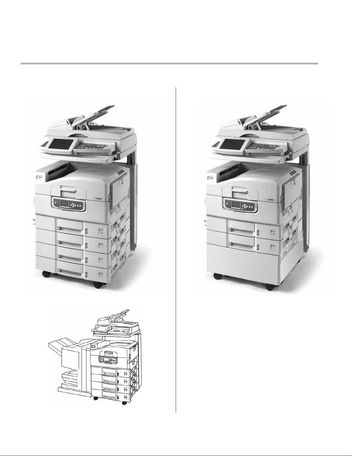
Configuration A
with High Capacity Feeder
ES3640e MFP
HCF.jpg
Configuration B
with Second Tray and Cabinet
ES3640e MFP
cab.jpg
With optional Finisher:
ES3640e
MFP
01_Finis
her.jpg
11
Page 2

ES3640e MFP Warning Icon.jpg
Do not begin installation
of this device
before reading
this entire Installation Guide.
Important safety warnings
follow.
22
Page 3
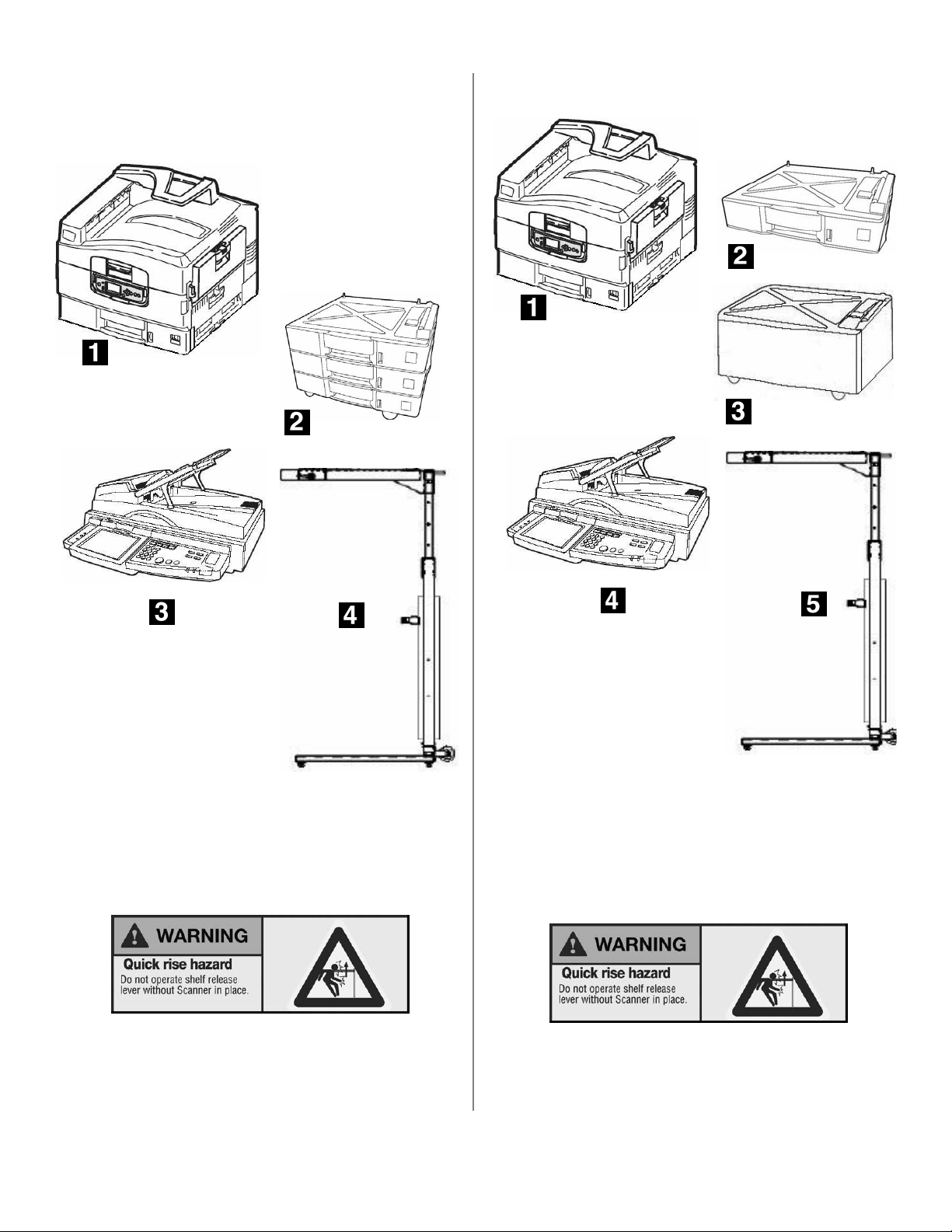
Overview
Configuration A
ES3640e MFP Configuration A is shipped in four units:
ES3640e MFP 05.jpg
ES3640e MFP 07.jpg
Configuration B
ES3640e MFP Configuration B is shipped in five units:
ES3640e MFP 04.jpg
ES3640e MFP 05.jpg
ES3640e MFP 06.jpg
ES3640e MFP 02.jpg
1
Printer
2
High-capacity Feeder
3
Scanner
4
Stand
ES3640e MFP 89a.jpg
ES3640e MFP 06.jpg
ES3640e MFP 02.jpg
1
Printer
2
Second Paper Tray
3
Cabinet
4
Scanner
5
Stand
ES3640e MFP 11.jpg
ES3640e MFP 89a.jpg
See page 11 for more information.
See page 11 for more information.
3
Page 4
Basic Requirements
Assembly
Space
Minimum Height
Minimum Width
•standard
• with optional finisher
Minimum Depth
72 inches (1.83 m)
78 inches (1.98 m)
109 inches (2.77 m)
73 inches (1.85 m)
Electrical:
Voltage: 110-127 VAC, 60 Hz
Power consumption, Operating:
• 1,500 W maximum
• 750 W typical
Environmental:
Temperature: 50-90°F
Humidity: 20-80% RH
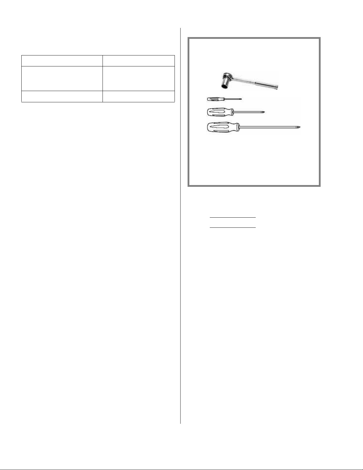
NOTE
You will need the following tools to
assemble the unit:
Socket
Wrenchj
pg
Screwdrviers.jpg
• 14 mm socket wrench
• Standard tip screwdriver
• Small Phillips tip screwdriver
• Larger Phillips tip screwdriver
Assembly involves the following steps:
Install the printer on its Support:
• Configuration A: High Capacity Feeder
• Configuration B
Prepare the printer.
Assemble the stand.
Mount the scanner on the Stand and Secure it to
the Shelf.
Make the Scanner Connections
Attach the Printer to the stand.
Finish the Installation.
Connect to the Network
: Cabinet/Second Paper Tray
4
Page 5
Step 1 Install the Printer on its
Support.
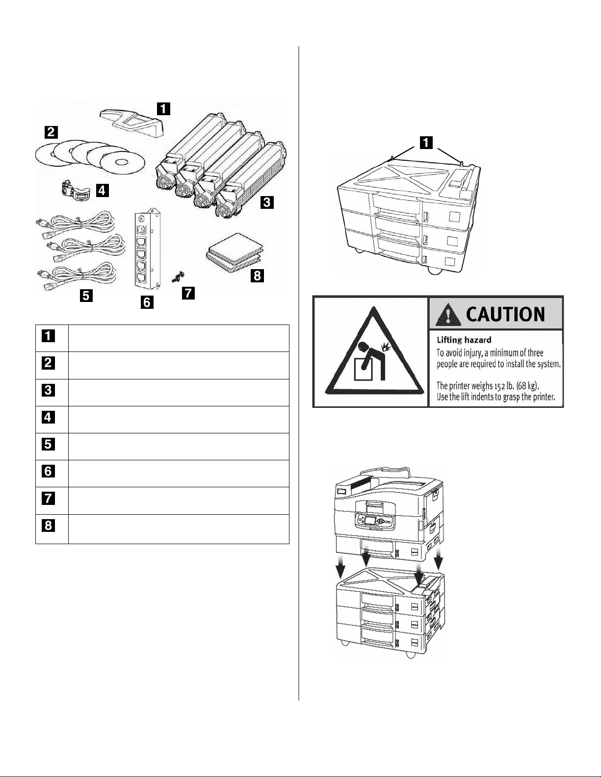
Accessories in Printer Box
ES3640e MFP 101.jpg
Configuration A: High Capacity Feeder
1. Unpack the High Capacity Feeder (HCF) and
remove any external shipping tape/restraints.
2. Unpack the printer and remove any external
shipping tape.
3. Note the location of the pins (
ES3640e MFP 07.jpg
Caution Hurt Back
1
) on the HCF:
Paper Catcher
CDs
Toner Cartridges
Ferrite Core for Network Connection
3 Power Cables (printer, scanner , main)
Power Strip
2 Screws for securing Power Strip to Stand
4 Light Shield Bags (for temporary storage of
drums when outside printer)
4. Lift the printer onto the HCF, aligning the holes on
the bottom of the printer with the pins on the
HCF.
ES3640e MFP 15.jpg
5. Go to “Step 2 Prepare the Printer” on page 7.
5
Page 6
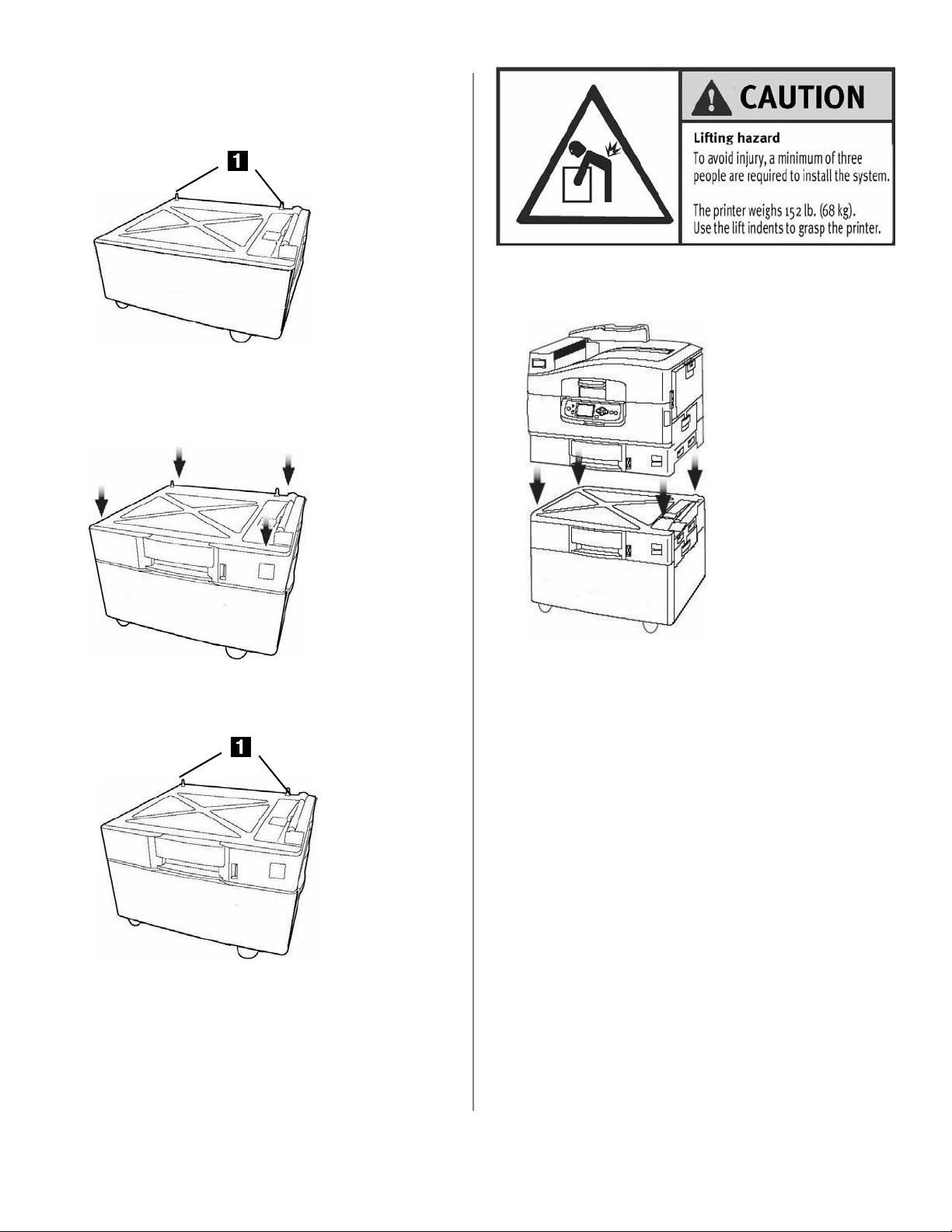
Configuration B: Cabinet/Second Tray
1. Unpack the printer cabinet and remove any
packing materials. Note the location of the pins
(
1
).
ES3640e MFP
11a.jpg
2. Unpack the second paper tray and remove any
packing materials.
3. Place the second paper tray on the cabinet
aligning the pins with the sockets.
ES3640e MFP
07a.jpg
Caution Hurt Back Icon.jpg
6. Align the printer with the second paper tray, then
lower the printer onto the tray/cabinet..
ES3640e MFP
15a.jpg
4. Unpack the printer and remove any shipping tape.
5. Note the location of the pins (1) on the tray.
ES3640e MFP
07b.jpg
6
Page 7
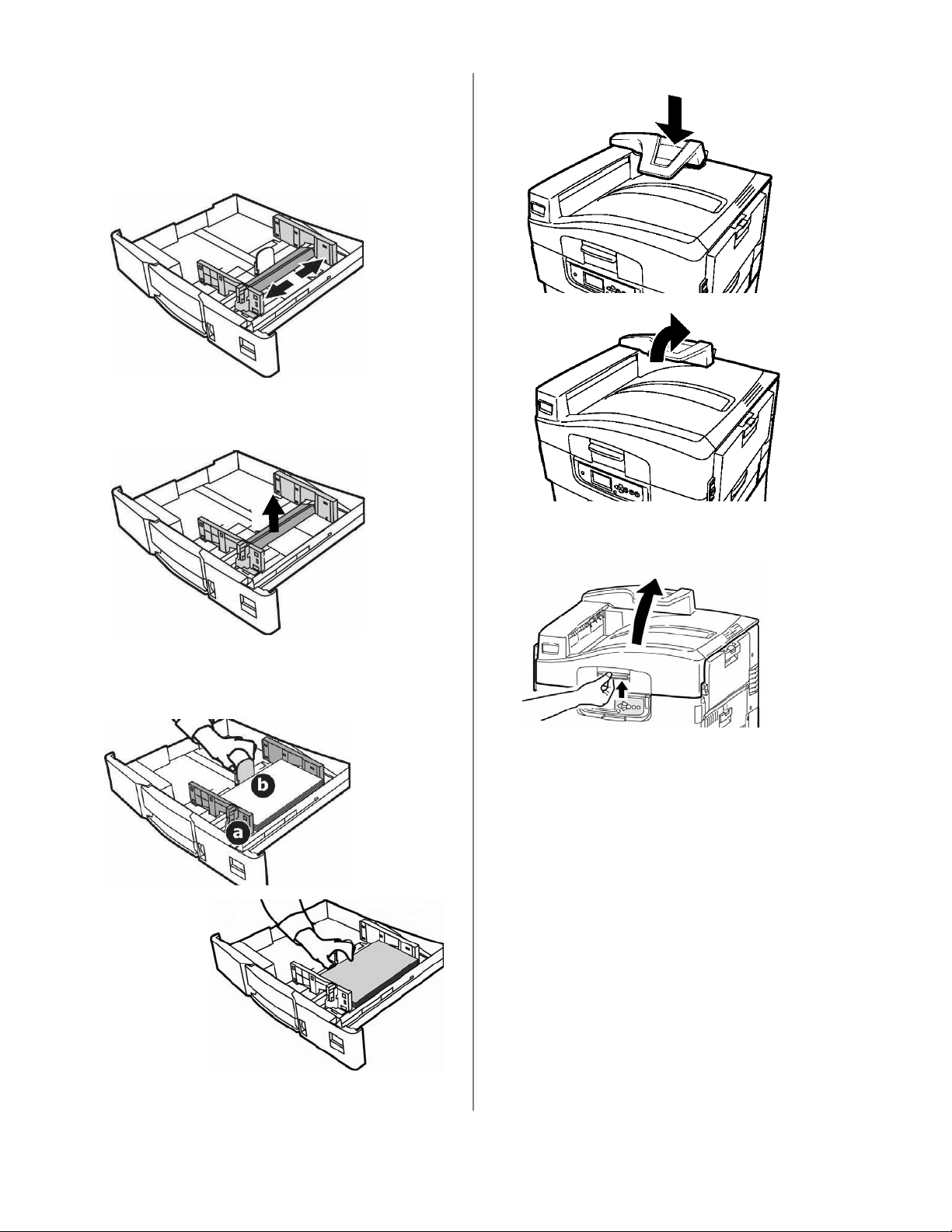
Step 2 Prepare the Printer.
1. Load paper in the trays.
a. Pull out the tray.
b. Squeeze the release on the paper guides and
move them apart.
ES3640e
MFP
27a.jpg
c. Remove the brightly colored shipping
restraint.
ES3640e
MFP
27b.jpg
2. Snap the Paper Catcher into the top of the printer.
ES3640e MFP
65a.jpg
ES3640e MFP
65b.jpg
3. Open the printer cover.
d. Set the guides (a, b) for the paper size and
load paper. Note: The default is letter size,
long edge feed.
ES3640e MFP
28a.jpg
ES3640e MFP
28b.jpg
open_top_cover_f
6_03.jpg
e. Close the tray.
7
Page 8
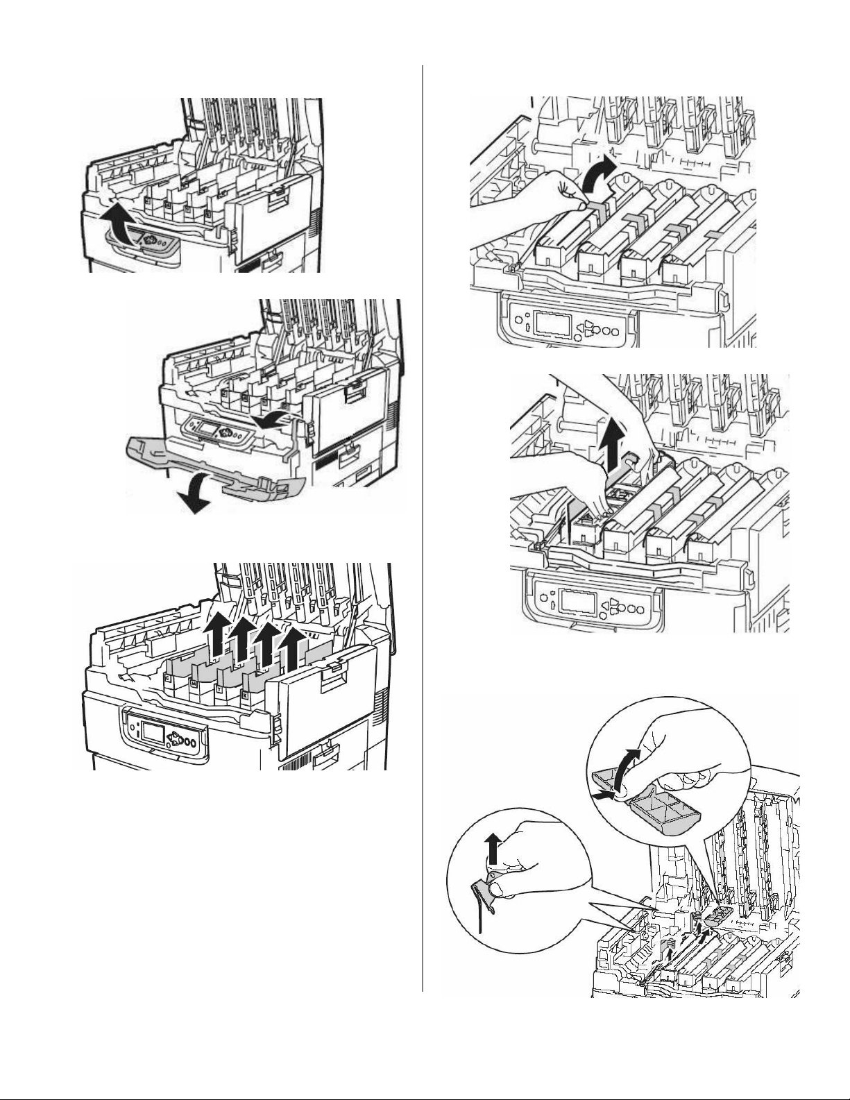
4. Lift the operator panel, open the front cover and
remove the shipping tape. Close the front cover.
ES3640e
MFP 16.jpg
ES3640e
MFP
17.jpg
6. For each drum, remove the tape and the
protective sheets.
ES36
40e
MFP
20.jp
g
5. Remove the colored image drum packing pieces.
ES3640e MFP 19.jpg
ES3640e MFP 21.jpg
7. Remove locks and seals for each drum.
ES3640e MFP 22.jpg
8
Page 9

8. For each color toner cartridge:
a. Shake the toner cartridge from side to side
to distribute toner.
ES3640e MFP 23.jpg
b. Remove sealing tape and insert the cartridge
into the corresponding color drum in the
printer.
ES3640e MFP 24.jpg
c. Lock the toner cartridge with the lever.
ES3640e MFP 26.jpg
9. Close the top cover.
10. Remove the backing from the strip on the back of
the Handy Reference Guide and apply the guide
to the printer.
ES3640e MFP 25.jpg
ES3640e MFP
15b.jpg
HandyRef_Co
ver.jpg
9
Page 10

Step 3 Assemble the Stand.
Accessories in the Stand Box
ES3640e MFP 99.jpg
8 Leg Bolts with Lock Washers and Flat
Washers for Stand Legs
2 Screws with Lock Washers and Flat Washers
for Bottom of Printer Brackets
2 Screws with Lock Washers and Flat Washers
for Plate Lock Mechanism
2 Screws with Lock Washers and Flat Washers
for attaching the Printer to the Bumper
Brackets
4 Small Screws with Lock Washers and Flat
Washers for Top of Printer Brackets
16 Medium Screws with Lock Washers and Flat
Washers
2 Cable Clips for attaching DCD cable (see
“Accessories in Scanner Box”“Accessories in
Scanner Box” on page 15) to the stand.
2 Bumper Brackets
3 Tie Wraps (to secure cabling)
ES3640e MFP 13a.jpg
2 Printer Brackets
10
Page 11

1. Unpack the stand, removing any shipping tape/
materials.
Stand Components:
ES3640e MFP 36a.jpg
ES3640e MFP
33a.jpg
ES3640e MFP 89a.jpg
The stand includes cylinders for moving the
scanner shelf up and down. Use extreme caution
when assembling the stand.
NEVER ATTEMPT TO RAISE OR LOWER THE
SHELF WITHOUT THE SCANNER BOLTED TO
IT
. Without the weight of the scanner on it, the
shelf could rise rapidly when released, potentially
causing severe injury.
• Scanner Support Shelf (1)
• Stand Frame with Posts (2)
• Two Legs with Casters (3)
ES3640e MFP
ES3640e MFP 86.jpg
TO PREVENT ANY POSSIBLE CRUSHING OF
FINGERS, KEEP YOUR HANDS AWAY FROM
THE POSTS AT THE BACK OF THE
SCANNER STAND WHEN MOVING THE
SCANNER SHELF DOWN
ES3640e MFP
90a.jpg
.
ES3640e MFP 85c.jpg
11
Page 12

2. Attach the legs with casters to either end of the
frame, using the eight leg bolts.
ES3640e MFP 92.jpg
3. Turn the stand over on its legs. Place the foam
bumpers in the brackets and attach the two
brackets to the stand using the medium screws
(two per bracket).
5. Place the scanner shelf on the frame and secure it
in place using four of the medium screws.
ES3640e MFP 89a.jpg
NEVER ATTEMPT TO RAISE OR LOWER THE
SHELF WITHOUT THE SCANNER BOLTED TO
IT
.
ES3640e MFP 86.jpg
ES3640e MFP 34.jpg
4. Unpack the plate lock mechanism.
ES3640e MFP
35.jpg
Important!
Do not lower the shelf until you have
placed and secured the scanner on the
shelf.
ES3640e MFP 36.jpg
ES3640e
MFP 37.jpg
12
Page 13

6.
Important!
Make sure the plate lock mechanism cables
are not twisted or kinked.
7. Hold the plate lock mechanism with the flat plates
facing the inner side wall of the shelf (cables
facing the outer side wall) and begin to feed it
into the channel between the walls.
ES3640e MFP 97.jpg
8. Pull the safety lever (
feeding the plate (
scan_stand_2_crop.jpg
Scan_Stand_7.jpg
2
1
) back and hold it while
) through the channel.
scan_stand_9_crop.jpg
13
Page 14

9. First person: pivot the release handle (1) on the
side of the stand down and hold it there. Second
person: hold the safety lever (
2
) back and
maneuver the square hole in the plate lock
mechanism (
3
) toward the handle key (4) inside
the shelf.
scan_stand_6_cri
op.jpg
11. Secure the plate lock mechanism with the two
plate lock mechanism screws.
ES3640e MFP 98 crop.jpg
12. Secure the plate lock cabling to the hole in the
shelf using one of the tie wraps provided with the
stand.
10. Rotate the release handle back and forth while
moving the hole in the plate lock until the handle
key (
1
) is firmly seated in the hole.
scan_stand_3.jpg
scan_stand_1.jpg
14
Page 15

Step 4 Mount the Scanner on
jpg
the Stand and Secure
it to the Shelf.
Accessories in Scanner Box
ES3640e MFP 89a.jpg
NEVER ATTEMPT TO RAISE OR LOWER
THE SHELF WITHOUT THE SCANNER
BOLTED TO IT
.
Important!
Make sure the shelf is in the extended
(uppermost) position.
ES3640e MFP 14.
Data, Control and Display (DCD) Cable
Locking Cap
Power Supply for Scanner
2 Ferrite Cores for Data Portion of DCD Cable
1. Unpack the scanner and Auto Document Feeder
(ADF) lid.
2. Install the ADF on the scanner.
ES3640e MFP 39.jpg
Lifting Hazard Icon.jpg
3. Place the scanner on the shelf, making sure the
foot on the right front of the scanner engages the
release plate (1) on the shelf.
ES3640e MFP 40.jpg
15
Page 16

4. Secure the scanner to the shelf using four
medium screws:
a.
First screw: Pull the safety lever (a) back to
expose the hole in the shelf. Insert one
medium screw up through the hole and into the
scanner, then tighten the screw (1)
scan_stand_4.jpg
.
5. Open the scanner lid and remove all packing
materials.
ES3640e
MFP
42.jpg
6. Close the scanner lid and remove all the shipping
tape.
Remaining three screws: Attach as follows: left
b.
front (
2
), left rear (3), and right rear (4)
scan_stand_5.jpg
scan_stan_8.jpg
ES3640e MFP
43.jpg
.
7. Slide the scanner lock (on the left side of the
scanner) to the UNLOCK position.
ES3640e MFP 59.jpg
16
Page 17

8. Insert the locking cap in the scanner lock.
ES3640e MFP 60.jpg
9. Lift the ADF paper tray, then extend the legs and
lower the tray into position.
ES3640e MFP 61.jpg
2. Attach the power strip to the lower left side
(viewed from the front) of the scanner stand
using the two screws provided in the printer box.
ES3640e MFP 45.jpg
3. Attach the scanner power supply (see
“Accessories in Scanner Box” on page 15) to the
keyhole inside the back of the stand.
ES3640e MFP
52a.jpg
ES3640e MFP 62.jpg
NOTE
If you are installing the optional finisher with the
system, see the instructions provided with the
finisher.
Step 5 Make Scanner
Connections
1. On the back of the scanner, connect the ADF cable
to the scanner.
ES3640e MFP
44.jpg
ES3640e MFP
46.jpg
4. Connect the power supply cable to the back of the
scanner.
ES3640e MFP 47.jpg
5. Connect the scanner power cable (see
“Accessories in Printer Box” on page 5) to the
17
Page 18

scanner power supply. then connect the other end
to the power strip.
ES3640e
MFP 57a.jpg
ES3640e MFP 48.jpg
6. Uncoil the DCD cable and mount the ferrite cores
(
1
) on either end of the USB data cable, next to
the ferrite cores built into the cable (cable and
ferrite cores are supplied in the scanner box: see
page 15), then attach the DCD cable lines to the
back of the scanner.
7. Secure the DCD cable to the top back of the shelf
using one of the cable clips and one of the
medium screws (“Accessories in Scanner Box” on
page 15).
ES3640e
MFP 107
crop.jpg
8. Use the tie wraps to attach the scanner power
supply cable to the DCD cable in two places.
ES3640e MFP 49.jpg
ES3640e MFP 102.jpg
18
Page 19

Step 6 Attach the Printer to
the Stand
1. Mount the brackets on the back of the printer:
a. Remove the two screws shown in the
illustration from the back of the printer.
Fire Hazard Warning Icon.jpg
Be sure to use the 15A AC power cord
supplied with the printer. Use of a power
cord NOT supplied with this printer, or an
extension cord, may result in overheating,
and could be a safety hazard.
2. Connect the printer power cord (supplied in the
printer box) to the printer.
ES3640e MFP 29.jpg
b. Attach the printer brackets. Use two small
screws at the top and one long screw at the
bottom of each bracket (see “Accessories in
the Stand Box” on page 10).
ES3640e MFP 30 crop.jpg
ES3640
e MFP
30a.jpg
Important!!
Do not connect this product to an
uninterruptible power supply (UPS). For
further information please contact Oki Data
at 1-800-OKIDATA .
19
Page 20

3. Move the printer back toward the stand.
ES3640e MFP
52.jpg
6. Connect the DCD cable lines to the printer.
ES3640e MFP 59a.jpg
4. Connect the printer power cord to the power strip.
ES3640e MFP 58a.jpg
5. Use the thumbscrews to attach the printer to the
bumper brackets on either side of the stand.
ES3640e MFP
55.jpg
7. Secure the lower end of the DCD cable to the left
side of the stand (above the power strip) using
one of the cable clips and one of the medium
screws.
ES3640e MFP 53.jpg
20
ES364
0e MFP
106a.j
pg
Page 21

Step 7 Finish the Installation
TO PREVENT ANY POSSIBLE CRUSHING OF
FINGERS, KEEP YOUR HANDS AWAY FROM
THE POSTS AT THE BACK OF THE SCANNER
STAND WHEN MOVING THE SCANNER
SHELF DOWN
1. Press on the release handle to lower the scanner
shelf.
.
ES3640e MFP
90a.jpg
ES3640e MFP 85b.jpg
Step 8 Connect to the
Network
NOTES
The Ethernet cable is not supplied with the
system.
In addition to the Ethernet port, the printer also
has a USB and a parallel port.
1. Remove the plug from the Ethernet port on the
printer.
2. Install the ferrite core supplied in the printer box
on a suitable Ethernet network cable:
Important
This safeguard is an FCC requirement.
In order to reduce electromagnetic interference—
”noise” that interferes with TVs or other
appliances—you must place the enclosed ferrite
core on the network cable.
ES3640e MFP 03d.jpg
2. Insert the main power cord into the power strip,
then connect it to a suitable 120-volt grounded
outlet.
ES3640e MFP
58.jpg
a. Loop the cable if necessary to keep the
ferrite core in place.
b. Place the open core about 1 inch from the
cable connector on the printer end.
ES3640e MFP
68.jpg
c. Press the two halves of the core together
until they click shut.
21
Page 22

3. Connect the ferrite core end of the Ethernet cable
to the printer, then connect the opposite end to
the network.
Install the Software
See the Software Install Guide and CDs supplied with
the printer.
Test the Scan and Print
Function
ES3640e MFP 64 Right.jpg
ES3640e MFP Basic System
1. Make sure the Copy Mode screen (the default) is
displayed. If it is not, press the Copy key on the
scanner.
2. Place a document face
down
on the scanner glass.
3. Press the Start key on the scanner.
up
on the ADF or face
ES3640e MFP 67.jpg
ES3640e MFP System with the
Optional Finisher Installed
1. Make sure the Copy Mode screen (the default) is
displayed. If it is not, press the Copy key on the
scanner.
2. Select the Finishing tab on the touch screen.
3. Select the desired finisher options on the touch
screen.
4. Place a document face up on the ADF or face
down
on the scanner glass.
5. Press the Start key on the scanner.
NOTE
If the paper jams, the finisher is not correctly
aligned with the printer.
Adjust the leveling feet on the finisher until the
paper feeds through smoothly.
22
Page 23

Page 24

Oki Data Americas, Inc., 2000 Bishops Gate Blvd., Mt. Laurel, NJ 08054-4620
Tel: (856) 235-2600 FAX: (856) 222-5320) my.okidata.com
Oki Data Americas, Inc., 2735 Matheson Blvd. East, Unit 1, Mississauga (Ontario), Canada L4W 4M8
Tél. : 1 800 654-3282 Téléc. : (905) 238-4427
OKI, ® / MD / MR, Oki Electric Industry Company, Ltd.
© 2005 Oki Data Americas, Inc. 59375602
 Loading...