

OKI ES1624n, ES1624MFP Service manual

Oki Data CONFIDENTIAL
ES1624n/ES1624MFP
Printer Maintenance Manual
050901A

Oki Data CONFIDENTIAL
42615101TH Rev.5 2 /

Oki Data CONFIDENTIAL
PREFACE
This manual describes the procedures of the maintenance of the ES1624n printers.
The document is produced for maintenance personnel use. For details on the procedures for handling
the ES1624n of printers, see its user documentation.
Note!
• The descriptions in this manual are subject to change without prior notice.
• In preparing the document, efforts have been made to ensure that the information in it is accurate.
However, errors may be crept into the document. Oki Data assumes no responsibility for any
damage resulting from, or claimed to be the results of, those repairs, adjustments or modifications to the printers which are made by users using the manual.
• The parts used for the printers are sensitive and, if handled improperly, may be damaged. It is
strongly recommended that the products are maintained by maintenance men registered with
Oki Data.
• Remove static electricity before working.
42615101TH Rev.5 3 /

Oki Data CONFIDENTIAL
CONTENTS
1. SPECIFICATIONS ............................................................................................... 7
1.1 System Configuration ........................................................................................................... 7
1.2 Printer Configuration .......................................................................................................... 10
1.3 Option Configuration .......................................................................................................... 13
1.4 Specifications ..................................................................................................................... 14
1.5 INTERFACE SPECIFICATIONS ........................................................................................ 18
1.5.1 Parallel Interface Specifications (ES1624n) ........................................................ 18
1.5.1.1 Parallel Interface ................................................................................... 18
1.5.1.2 Parallel Interface Connector and Cable ................................................ 18
1.5.1.3 Parallel Interface Level .......................................................................... 18
1.5.1.4 Timing Charts ........................................................................................ 19
1.5.1.5 Parallel I/F Signals ................................................................................ 20
1.5.2 Universal Serial Bus (USB) Interface Specifications(ES1624n)............................... 21
1.5.2.1 USB Interface ........................................................................................ 21
1.5.2.2 USB Interface Connector and Cable ..................................................... 21
1.5.2.3 USB Interface Signals ........................................................................... 21
1.5.3 Network Interface Specifications(ES1624n) ..........................................................22
1.5.3.1 Network Interface .................................................................................. 22
1.5.3.2 Network Interface Connector and Cable ............................................... 22
1.5.3.3 Network Interface Signals ..................................................................... 22
2. OPERATION DESCRIPTION ............................................................................ 23
2.1 Electrophotographic Process Mechanism .......................................................................... 23
2.2 Printing Processes ................................................................................................................ 28
3. PRINTER INSTALLATION ................................................................................. 38
3.1 Precautions and Prohibition .................................................................................................. 38
3.2 Printer Unpacking Procedure ................................................................................................40
3.3 Printer Installation Instructions .............................................................................................. 41
3.4 Packed Units and Attachments ............................................................................................. 42
3.5 Assembly Procedure ............................................................................................................. 43
3.5.1 Printer Main Body .................................................................................................... 43
3.5.2 Power Cable Connection ......................................................................................... 48
3.5.3 Installation of Optional Components ........................................................................ 51
3.5.4 Checking of Optional-Component Recognition........................................................ 60
3.6 MenuMap Printing ................................................................................................................. 61
3.7 Connection Procedures ........................................................................................................ 64
3.8 Checking of User Paper ........................................................................................................ 66
4. PARTS REPLACEMENT ................................................................................... 67
4.1 Precautions in Replacing Parts .......................................................................................... 67
4.2 Part Replacement Procedures ........................................................................................... 69
4.2.1 Left Side Cover ..................................................................................................... 69
4.2.2 Right Side Cover .................................................................................................. 70
4.2.3 Face-Up Tray........................................................................................................ 71
4.2.4 Rear Cover ........................................................................................................... 72
4.2.5 LED Assy / LED Assy-Springs.............................................................................. 73
4.2.6 Controller PCB...................................................................................................... 74
4.2.7 Print Engine Controller PCB ................................................................................. 76
4.2.8 Top Cover Assy .................................................................................................... 79
4.2.9 Top Cover ............................................................................................................. 80
4.2.10 Controller Panel Assy ........................................................................................... 81
4.2.11 Board-PRP / Top Cover Handle ........................................................................... 82
4.2.12 Low-Voltage Power Unit / ID-FAN / Low-Voltage Power Unit FAN /
Hopping Motor / Fuser Motor................................................................................ 83
42615101TH Rev.5 4 /

Oki Data CONFIDENTIAL
4.2.13 Board-PRT............................................................................................................ 84
4.2.14 Guide-Eject Assy / Color Registration Assy / Board-PRM.................................... 85
4.2.15 FAN (Fuser) / Belt Motor / High Voltage Power Supply Board / Cover Open Switch 87
4.2.16 MPT-Assy ............................................................................................................. 88
4.2.17 Feeder Unit / Board-RSF / MPT Hopping Roller / Frame Assy Separator /
Cover-Front .......................................................................................................... 89
4.2.18 Main Motors / Solenoid / Paper-End Sensor ........................................................ 90
4.2.19 Feed Roller ........................................................................................................... 92
4.2.20 Shaft Assy-Eject (FU) / Shaft Assy-Eject (FD) / Eject Sensor .............................. 93
4.2.21 Fuser Unit ............................................................................................................. 94
4.2.22 Belt Unit ................................................................................................................ 95
4.3 Parts to lubricate ................................................................................................................ 96
5. MAINTENANCE MENU ................................................................................... 111
5.1 System Maintenance Menu(For Maintenance Staff) ........................................................ 111
5.2 Maintenance Utility ........................................................................................................... 114
5.3 Changing the display language ........................................................................................ 118
5.4 Maintenance Menu Function of the User Menu ............................................................... 119
5.4.1 Maintenance Menu(For End-Users) ................................................................... 119
5.4.2 Self-diagnostic Mode .......................................................................................... 120
5.4.2.1 Operator panel .................................................................................... 120
5.4.2.2 Normal self-diagnostic mode (level 1) ................................................. 124
5.4.2.2.1 Entering self-diagnostic mode (level 1) ............................... 126
5.4.2.2.2 Exiting self-diagnostic mode ............................................... 126
5.4.2.3 Switch scan test .................................................................................. 127
5.4.2.4 Motor and clutch test ........................................................................... 130
5.4.2.5 Test printing ........................................................................................ 132
5.4.2.6 Color registration adjustment test ....................................................... 137
5.4.2.7 Print density adjustment test ............................................................... 137
5.4.2.8 Consumable counter display ............................................................... 138
5.4.2.9 Counter display of numbers of prints and images ............................... 138
5.4.2.10 Switching between Factory and Shipping modes ............................... 139
5.4.2.11 Self-diagnosis function setting ............................................................ 140
5.4.2.12 Waste toner counter display................................................................ 141
5.4.2.13 LED head serial number display ......................................................... 141
5.4.2.14 Operator panel display ........................................................................ 142
5.4.3 Printing on Controller-Equipped Printer on a Standalone Basis ......................... 147
5.4.4 Switch Press Functions at Printer Power-On ..................................................... 148
5.5 Settings after Parts Replacement .................................................................................... 149
5.5.1 Instructions to exchange the engine control board ............................................. 149
5.5.2 EEPROM Setting after ARC Board/SPY Board/SPA Board Replacement ........ 152
5.5.3 Destination Setting [Check Method: Printing demo page (ES1624n),
Printing Menu Map (ES1624n)] .......................................................................... 153
5.6 Settings by Hand for Print Density Adjustment ................................................................ 155
6. REGULAR MAINTENANCE ............................................................................ 156
6.1 Parts Replaced Regularly ................................................................................................ 156
6.2 Cleaning ........................................................................................................................... 156
6.3 Cleaning the LED Lens Array .......................................................................................... 156
6.4 Cleaning the Pick-up Roller and the Pad ......................................................................... 158
6.5 Cleaning the Printer Inside ............................................................................................... 159
7. TROUBLESHOOTING PROCEDURES .......................................................... 161
7.1 Precautions before troubleshooting ................................................................................. 161
7.2 Precautions before handling an abnormal image ............................................................ 161
7.3 Precautions upon handling an abnormal image............................................................... 161
7.4 Preparing for Troubleshooting ......................................................................................... 161
42615101TH Rev.5 5 /

Oki Data CONFIDENTIAL
7.5 Troubleshooting Procedure .............................................................................................. 161
7.5.1 LCD message list ............................................................................................... 162
7.5.2 Preparing for troubleshooting ............................................................................. 174
7.5.2.(1)LCD Display Malfunction ................................................................................. 176
7.5.2.(2)Irregular Operation of the device after turning on the power ........................... 179
7.5.2.(3)Paper Feed Jam(Error 391:1st Tray)............................................................... 189
7.5.2.(4)Paper Feed Jam (Error 390:Multi-purpose Tray)............................................. 191
7.5.2.(5)Paper Path Jam(Error 381) ............................................................................. 193
7.5.2.(6)Paper Exit Jam(Error 382)............................................................................... 198
7.5.2.(7)Duplex Print Jam(Error 370,371,372,373,383) ............................................... 201
7.5.2.(8)Paper Size Error (Error 400) ........................................................................... 203
7.5.2.(9)ID Unit Up-Down Error(Service Call 140-143)................................................. 204
7.5.2.(10)Fuser Unit Error(Error 170-177) .................................................................... 205
7.5.2.(11)Motor Fan Error(Error 120,127,051) .............................................................. 206
7.5.2.(12)Print Speed is Slow (Low Performance)........................................................ 207
7.5.2.(13)Option unit is not recognized ......................................................................... 207
7.5.2.(14)LED head is not recognized(Error 131,132,133,134) .................................... 208
7.5.2.(15)Toner cartridge is not recognized(Error 540,541,542,543) ............................ 209
7.5.2.(16)Fuse Cutout Error (Error 150-155) ................................................................ 213
7.5.2.(17)Dew Condensation Errors (Error 123) ........................................................... 213
7.5.3 Image Problem Troubleshooting ........................................................................ 214
7.5.3.(1)Color is totally pale (Fig.7.2 A )........................................................................ 215
7.5.3.(2)Background is dirty (Fig.7.2 B ) ....................................................................... 216
7.5.3.(3)Blank Print (Fig.7.2 C ) .................................................................................... 217
7.5.3.(4)Vertical lines are printed .................................................................................. 218
7.5.3.(5)Cyclic Print Trouble (Refer to Fig.7.2 E )......................................................... 219
7.5.3.(6)Color drift is wide. ............................................................................................ 220
7.5.3.(7)Solid Black Print .............................................................................................. 221
7.5.4 Actions Taken after Forced HDD/Flash Initialization .......................................... 222
7.5.5 Network Troubleshooting.................................................................................... 223
7.5.6 Displaying Details of Service Call Error Codes (ES1624n) ................................ 224
7.6 Fuse Checking ................................................................................................................. 225
8. CONNECTION DIAGRAM ............................................................................... 226
8.1 Resistance Checks .......................................................................................................... 226
8.2 Program/Font ROM Layouts ............................................................................................ 230
42615101TH Rev.5 6 /
1. SPECIFICATIONS
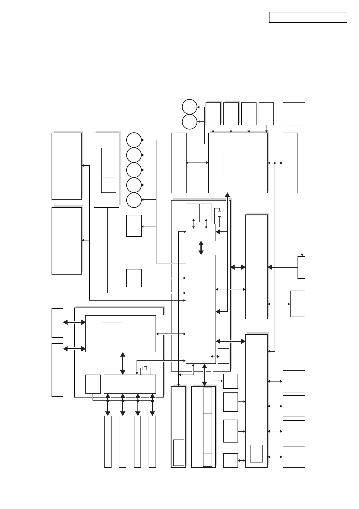
1.1 System Configuration
ES1624n
Figure 1-1-1 shows the system configuration of ES1624n
IN1 IN2 WR
Oki Data CONFIDENTIAL
M
HEAT
Color
Color
M
BELT
M
HOP
M
CID
M
MID
M
YID
Belt Unit
Registration
Belt Unit Fuse
Board-Right
Registration
Cut-Out
Board-Left
Driver Relay Board
Sensor
Density
Up & Low/
Fuser Fuse Cut-Out/
EXIT
Sensor
Thermistor
Inlet
Fuser
Duplex Board 2nd Tray Board
HDD
LAN, USB, Centro I/F
LVDS
CU Board
Front Sensor Board
CU-FAN
Video
Interface
fsync × 4,
Isync, wclk)
(data8bit × 4,
Driver
M
KID
Solenoid
Paperfeed
1st
P. E
Sensor
DCON
Command
CU Area
50MHz
DCON I/F, LSYNC
Interface
PU-Board
Humidity Signals
Environment Temperature
8M bit
FLASH
SRAM
MCON CPU
256Kbit
Color Registration,
Fuse Cut-Out,
28MHz
Signals
Density, Thermistor
Exit,
Motor Control
EEPROM
ID
0VL, 0VP
3.3V, 5V, 24V,
Control, etc
Fan, Heater
High Voltage Interface,
Fan Control, Cover-Open
FAN
Thermistor
Heater Frame
AC-SW
FAN
Low-Voltage
Y LED HEAD
K LED HEAD
C LED HEAD
M LED HEAD
Board
Operator Panel
Toner Sensor Board
Sensor
Environment
cut-out
Image drum fuse
sensor
C toner
sensor
M toner
sensor
Y toner
sensor
K toner
Open
Cover-
Belt
Thermistor
Fusing
Sensor
FAN
High Voltage Board Low Voltage Board
Down
ID UP/
K-ID Y-ID M-ID C-ID
Figure 1-1-1
42615101TH Rev.5 7 /
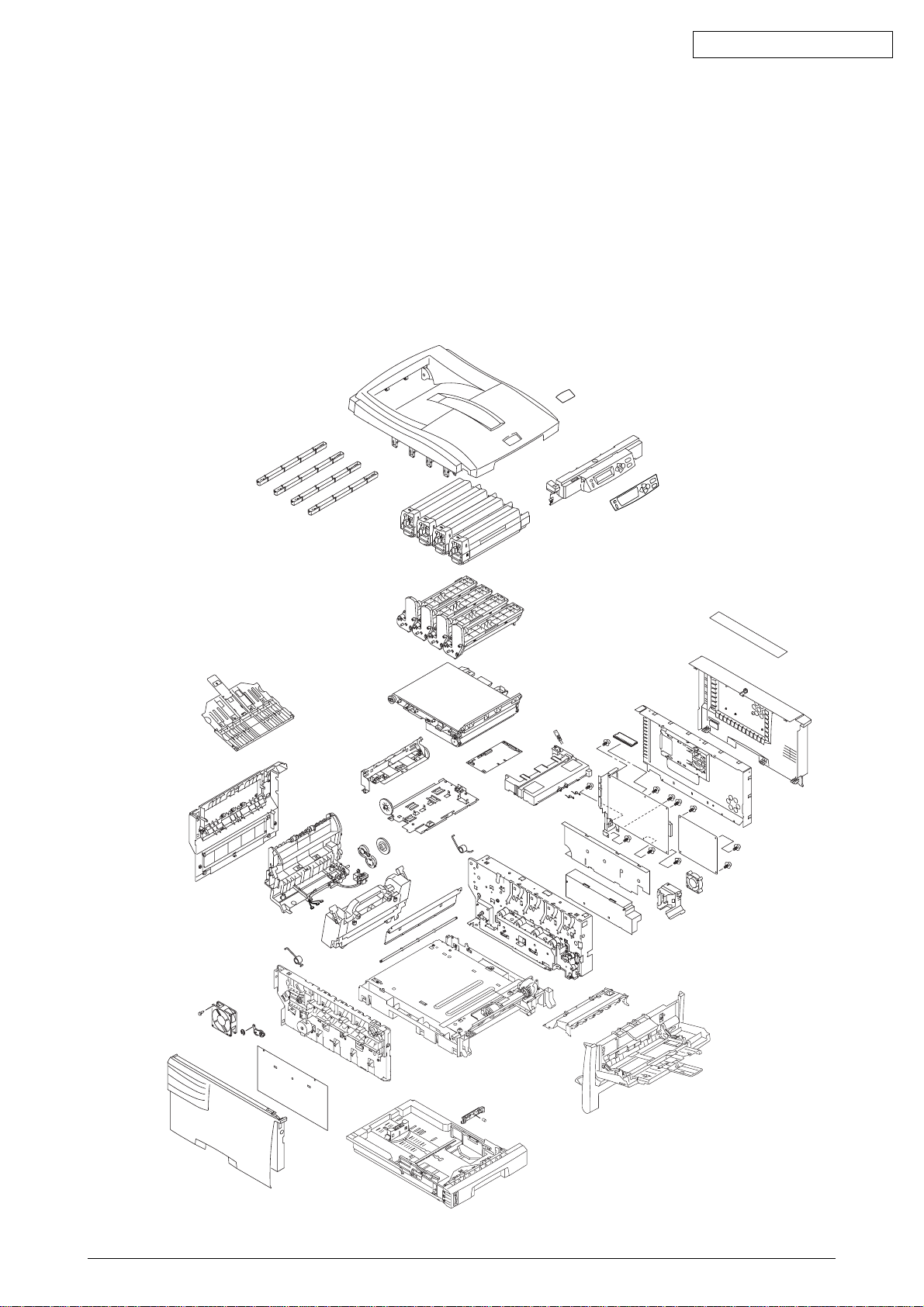
1.2 Printer Configuration
The inside of ES1624n printers is composed of the following:
• Electrophotographic Processor
• Paper Paths
• Controller Block (CU and PU)
• Operator Panel
• Power Units (High Voltage Unit and Low Voltage Unit)
Figure 1-2-1 shows the configuration of each printer.
Oki Data CONFIDENTIAL
Figure 1-2-1
42615101TH Rev.5 10 /
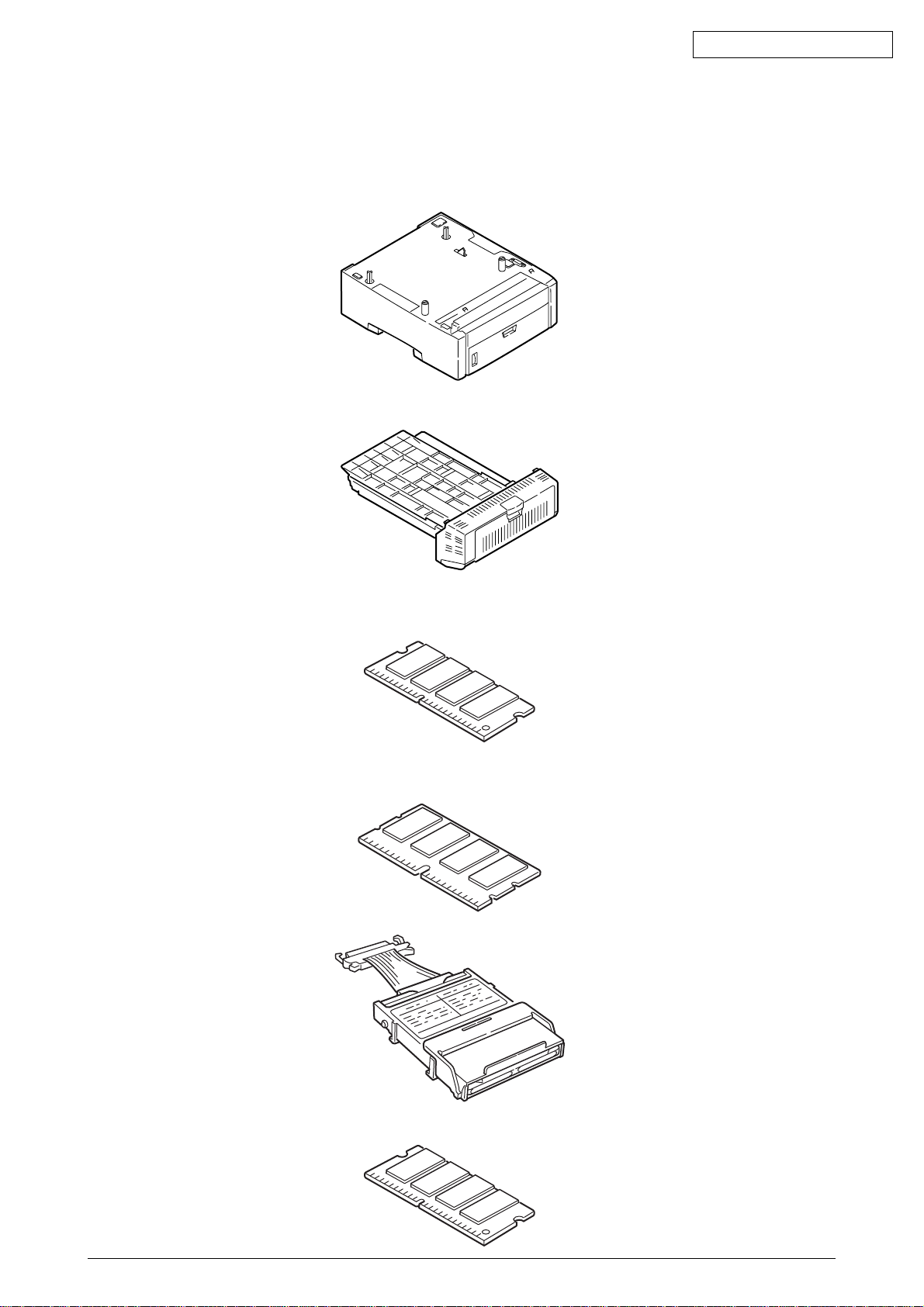
1.3 Option Configuration
The following options are available for ES1624n.
(1) 2nd Tray
(2) Duplex Unit
Oki Data CONFIDENTIAL
(3) Expansion Memory 64 MB
Recommend to add an optional memory for duplex print, banner print.
(4) Expansion Memory 64/256 MB
Recommend to add an optional memory for duplex print, banner print.
(5) Hard Disk
(6) Upgrade DIMM
42615101TH Rev.5 13 /
1.5 INTERFACE SPECIFICATIONS
1.5.1 Parallel Interface Specifications (ES1624n)
1.5.1.1 Parallel Interface
Item Description
Mode Compatibility mode, Nibble mode, ECP mode
Data bit length 8 bits: Compatibility mode, 4bits: Nibble mode,9 bits: ECP mode
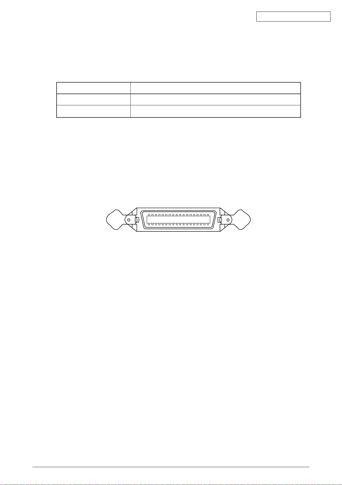
1.5.1.2 Parallel Interface Connector and Cable
1) Connector
Printer side: 36-pin receptacle
Type 57LE-40360-12 (D56) (made by Daiichi Denshi) or equivalent
Cable side: 36-pin plug
Type 57FE-30360-20N (D8) (made by Daiichi Denshi) or equivalent
Oki Data CONFIDENTIAL
Connector Pin Arrangement Viewed from Cable Side
2) Cable
Cable length: 1.8 m max.
(A shielded cable composed of twisted pair wires is recommended for noise prevention.)
1.5.1.3 Parallel Interface Level
LOW: 0 V to +0.8 V
HIGH: +2.4 V to 5.0 V
118
1936
42615101TH Rev.5 18 /
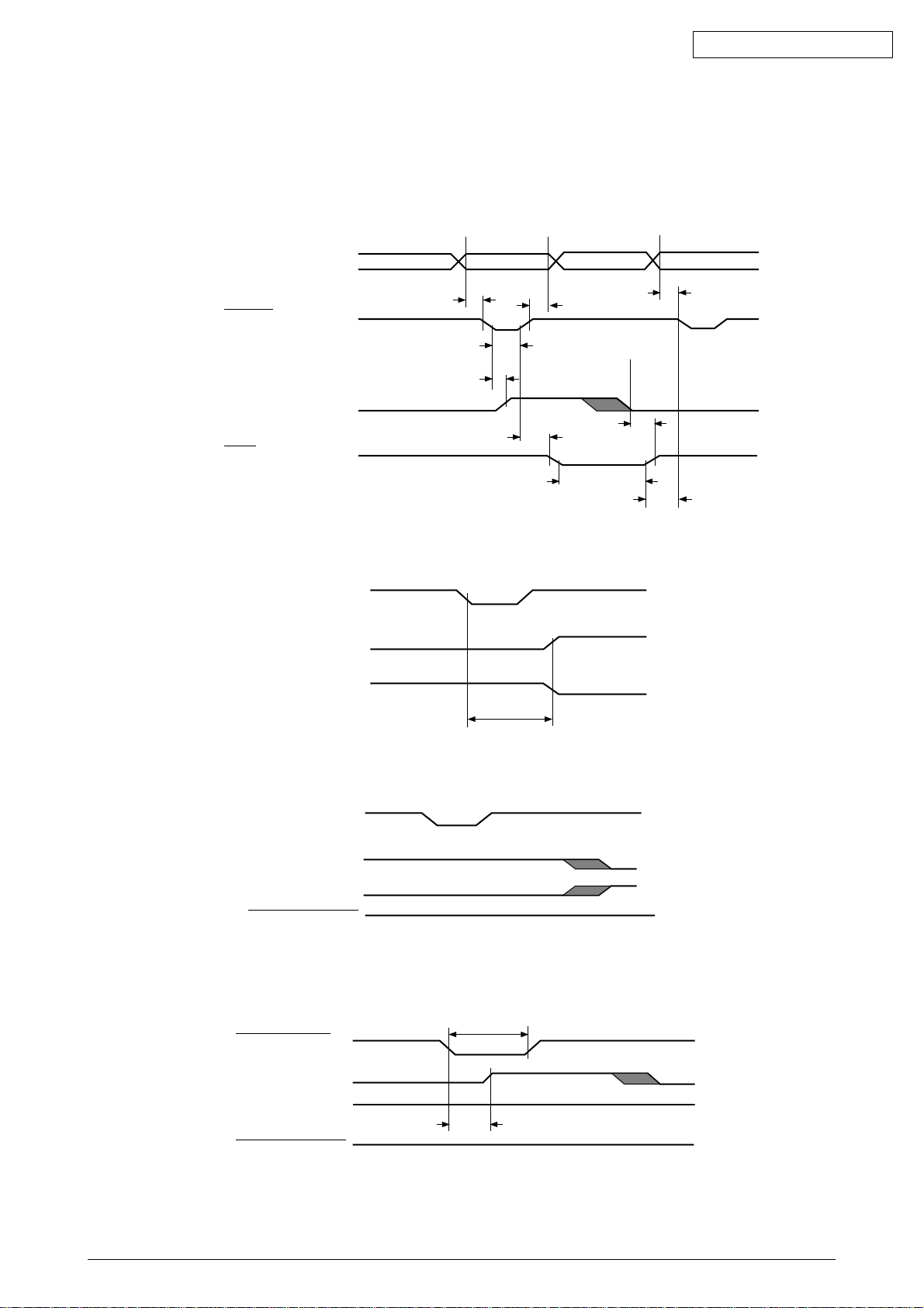
1.5.1.4 Timing Charts
Compatible mode
a) Data receiving timing
PARALLEL DATA
(DATA BITs 1 to 8)
nStrobe
0.5 µs min.
0.5 µs min.
0.5 µs max.
0.5
0.5
µ
s min.
µ
s min.
Oki Data CONFIDENTIAL
BUSY
0 min.
nAck
0.5 µs to 3 µs
b) On-line (off-line switching timing by ON-LINE SW)
ON-LINE SW
BUSY
SELECT
100 ms max.
c) Off-line (on-line switching timing by ON-LINE SW)
ON-LINE SW
BUSY
0 min.
0 min.
SELECT
ACKNOWLEDGE
d) nlnit timing (invalid by default)
* Menu-set
50 µs min.
INPUT. PRIME
BUSY
SELECT
ACKNOWLEDGE
42615101TH Rev.5 19 /
5µs max.

Oki Data CONFIDENTIAL
1.5.1.5 Parallel I/F Signals
Table 1-1 shows interface signal names and pin numbers.
Table 1-1 Signals
Pin No. Signal Name Signal Direction Functions
1 Nstrobe (HostClk) →PR Pulse for reading data in at trailing edge.
2 DATA 1
3 DATA 2
4 DATA 3 8-bit parallel data.
5 DATA 4 →PR Each signal is HIGH when data is logical 1 and
6 DATA 5 LOW when it is logical 0.
7 DATA 6
8 DATA 7
9 DATA 8
10 nAck (PtrClk) ←PR Indicates the completion of data reception.
11 Busy (PtrBusy) ←PR Indicates whether the printer is ready for receiving
data. Data cannot be received while the signal is
HIGH.
12 PError (AckDataReq) ←PR Indicates paper error when held HIGH.
13 Select (Xflag) ←PR HIGH without exception when the parallel
interface is enabled.
14 NAutoFd (HostBusy) →PR Used in bidirectional communication.
15 - - Unassigned.
16 GND - Signal ground.
17 FG - Chassis ground.
18 +5V ←PR Used for supplying +5V. Power cannot be
supplied to the outside of the printer.
19
~ GND - Signal ground.
30
31 Nlnit (nlnit) →PR Initializes the printer when held LOW.
32 NFault (nDataAvail) ←PR LOW during alarm.
33 GND - Signal ground.
34 - - Unassigned.
35 HILEVEL ←PR Pulled up to +5V at 3.3KΩ inside the printer.
36 Nselectin →PR Used in bidirectional communication. Low without
(IEEE 1284 active) exception in compatible mode.
Note:
42615101TH Rev.5 20 /
Parenthesized signal names are used in nibble mode.
Only functions in compatible mode are listed.
This printer supports the IEEE std 1284-1994 nibble mode. Note that, when used with
personal computers or cables that do not comply with the standards, the printers may
exhibit unpredictable behavior.
1.5.2 Universal Serial Bus (USB) Interface Specifications(ES1624n)
1.5.2.1 USB Interface
(1) Basic specifications
Conforms to USB specification, revision 1.1.
(2) Transmission mode
Full speed (max. 12 Mbps + 0.25%)
(3) Power Control
Self-power device
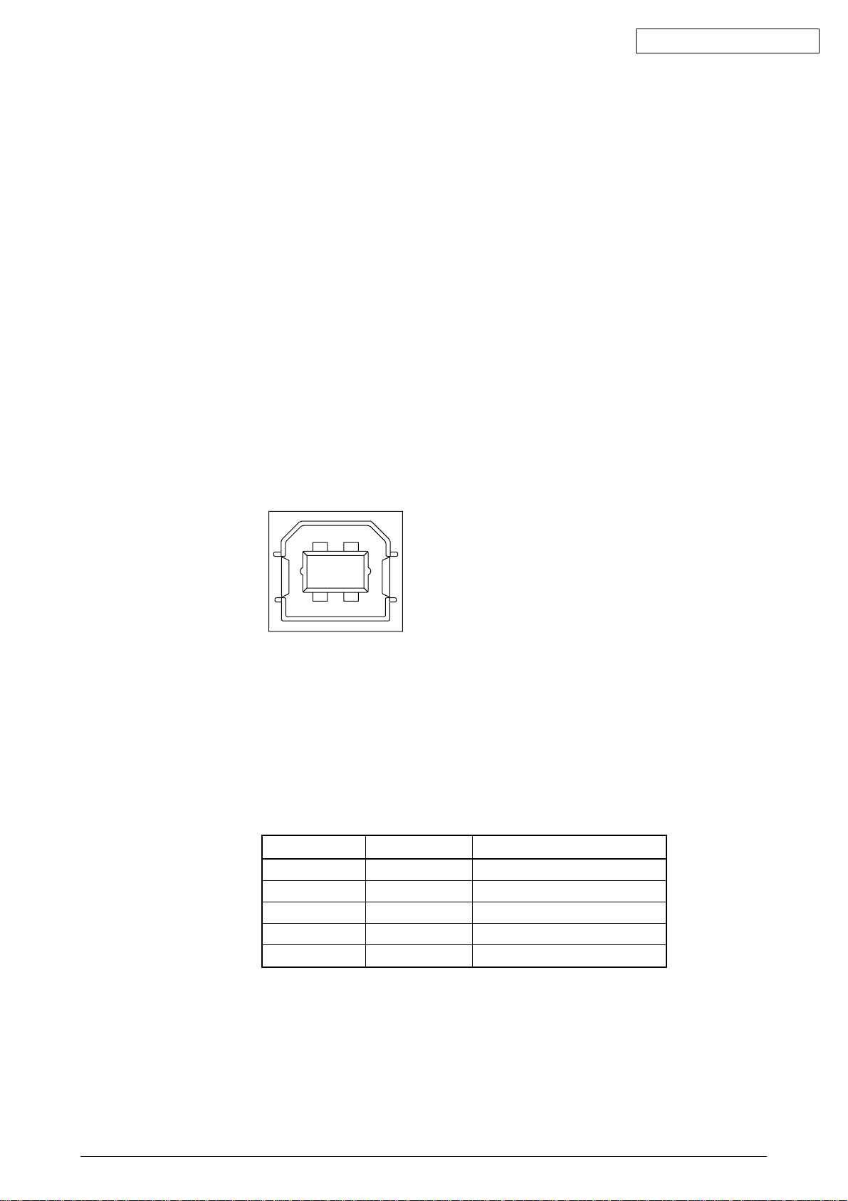
1.5.2.2 USB Interface Connector and Cable
(1) Connector
Printer side: Type B receptacle
Upstrem port
UBB-4R-D14T-1 (made by JST) or equivalent
Oki Data CONFIDENTIAL
Connector pin layout
2
34
Cable side: Type B plug
(2) Cable
Cable length: 5 m max. (cable compliant with USB specification, revision 1.1)
(A shielded cable must be used.)
1.5.2.3 USB Interface Signals
1 Vbus Power Supply (+5V) (red)
2 D - Data transmission (white)
3 D + Data transmission (green)
4 GND Signal ground (black)
Shell Shield
1
R1 Function
42615101TH Rev.5 21 /

1.5.3 Network Interface Specifications(ES1624n)
1.5.3.1 Network Interface
(1) Basic specifications
Network protocol
TCP/IPSpecification Network layer
ARP, RARP, IP, ICMP
Transport layer
TCP, UDP
Application layer
LPR, FTP, TELNET, HTTP, BOOTP, SMTP
1.5.3.2 Network Interface Connector and Cable
(1) Connector
100 BASE-TX / 10 BASE-T
Connector pin layout
Oki Data CONFIDENTIAL
18
(2) Cable
RJ-45 anti-Shield twist pair cable with connector (Category 5 recommended)
1.5.3.3 Network Interface Signals
Pin No. Signals Signal Direction Functions
1 TXD+ FROM PRINTER Send Data +
2 TXD- FROM PRINTER Send Data -
3 RXD+ TO PRINTER Received Data +
4 - - Unassigned
5 - - Unassigned
6 RXD- TO PRINTER Received Data -
7 - - Unassigned
8 - - Unassigned
42615101TH Rev.5 22 /

2. Operation Description
2.1 Electrophotographic Process Mechanism
(1) Electrophotographic Process
Following describes the outline of an electrophotographic process incorporated into printers.
1. Charging
Applying a voltage to a charging (CH) roller charges the surface of an optical
photoconductive (OPC) drum.
2. Exposure
The surface of the drum having a charge is exposed to light an LED head emits under
each image signal. Segments of the surface have a reduced charge according to the
intensities of the light they receive, a static latent image being created on the surface
based on electrical potentials on the surface
3. Development
Charged toner is attracted to the latent image of the drum by static electricity and
makes the image visible on the surface of the drum.
Oki Data CONFIDENTIAL
4. Transfer
Paper is brought into contact with the drum, and applied with a charge by a transfer
roller from the back, the toner image being transferred to the paper.
5. OPC Drum Cleaning
A drum cleaning blade removes residual toner from the drum after the transfer.
6. Transfer Belt Cleaning
A belt cleaning blade removes residual toner from a transfer belt.
7. Fusing
Heat and pressure fuses the toner image to the paper.
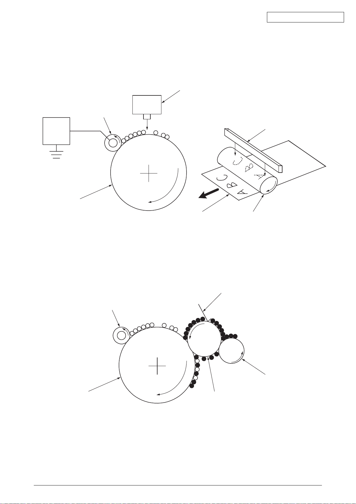
(2) Charging
Voltage is applied to a CH roller contacting the surface of an OPC drum, depositing a charge
over the surface.
CH Roller
Power
Supply
Unit
-
-
-
-
-
-
OPC Drum
42615101TH Rev.5 23 /
Oki Data CONFIDENTIAL
(3) Exposure
The surface of the charged drum is exposed to light emitted from an LED head. Charges of
segments of the surface are reduced according to the intensities of the light the segments
receive, a static latent image being created on the surface.
LED Head
CH Roller
Power
Supply
Unit
OPC Drum
(4) Development
Toner is attracted to the latent image on the surface of the drum, making the image a toner
image.
-
-
-
-
-
-
-
-
-
Paper
1. The sponge roller supplies toner onto the developing roller.
Developing Blade
LED Head
OPC Drum
CH Roller
-
-
-
-
-
-
-
-
-
-
-
-
OPC Drum
Developing Roller
2. The latent image on the surface of the drum is made visible by the toner.
Sponge Roller
42615101TH Rev.5 24 /

Oki Data CONFIDENTIAL
(5) Transfer
The paper made contact with the surface is applied with a charge by the roller from the back.
Applying high voltage provided by a power supply to the roller transfers the roller-induced
charge to the surface of the paper at the contact between the roller and the paper, attracting
the charged toner from the surface of the drum to the surface of the paper.
-
-
-
OPC Drum
-
-
-
-
-
-
-
-
-
-+-
+
Transfer Roller
+
+
-+-+-+-+-+-
-+-
-+-
-
-
-
+
+
-
+
-
+
-
+
-
+
Paper
Transfer Belt
Power
Supply
Unit
42615101TH Rev.5 25 /
Oki Data CONFIDENTIAL
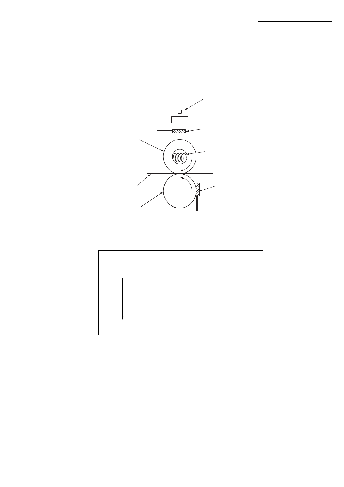
(6) Fusing
When passing between a heat roller and a backup roller, the toner image transferred to the
paper is fused into place with heat and pressure.
A safety thermostat is provided and, when the temperature of the heat roller rises to or exceeds
a predetermined temperature, it opens, cutting off voltage supply to the heater.
Thermostat
Thermistor
Heat Roller
Halogen Lamp
Paper
Backup Roller
Fusing Temperature Settings
Media Weight
Paper Type Settings
Light
Heavy
Light
Medium
Heavy
U.Heavy
OHP
Thermistor
Temperature Settings
Warm
High
Warm
Low
Low
42615101TH Rev.5 26 /
Oki Data CONFIDENTIAL
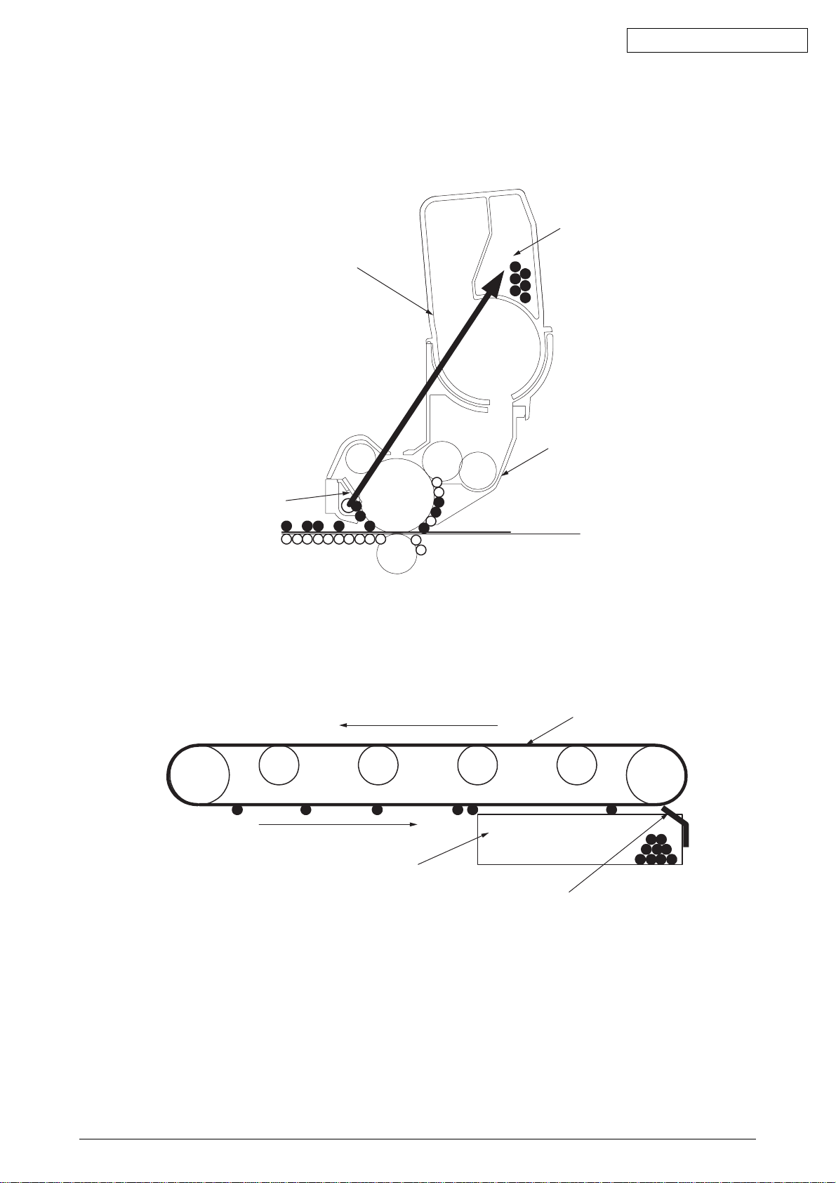
(7) OPC Drum Cleaning
Unfused, residual toner on the drum is scraped off with a drum cleaning blade, and collected
in the waste toner area of a toner cartridge.
Waste Toner Area
Toner Cartridge
Image Drum (ID) Unit
-
Drum Cleaning Blade
-+-
-+-+-+-
-+-
-+-
+
+
+
+
-
-
-
+
-
+
(8) Transfer Belt Cleaning
Residual toner on a transfer belt is scraped off with a belt cleaning blade, and collected in the
waste toner box of a transfer belt unit.
Transfer Belt
Waste Toner Box
Belt Cleaning Blade
42615101TH Rev.5 27 /
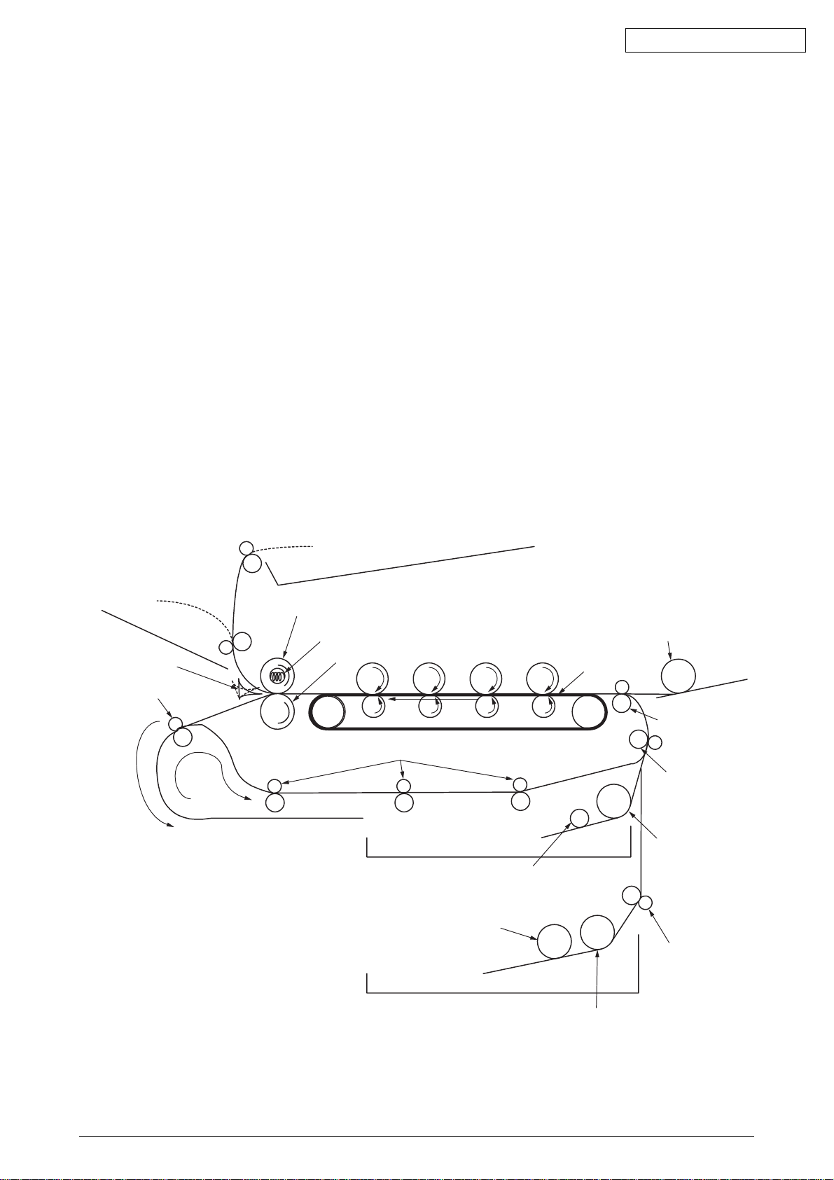
2.2 Printing Processes
Paper fed from a tray 1 or 2 is forwarded by Hopping roller, Registration Roller L and Feed roller.
When feeding paper from a multiple tray, it is forwarded by a MPT Hopping roller and Registration
Roller U. Then, the paper is moved onto a transfer belt and, through K, Y, M and C electrophotographic
processes performed taking their turns, a yet-to-be-fused toner image is produced on the paper.
While the paper passes through a fuser unit, heat and pressure fuses the toner to the paper. After
the fusing process, the paper is ejected to a face-up or face-down stacker, whichever is selected
according to whether the face-up stacker is opened.
These operations are performed in single-side printing. Following are operations in two-side
(duplex) printing.
In duplex printing, paper passed through a fuser unit after it is first printed on the back is fed into
a duplex unit via a dup-in separator. Reversing roller’s reversing operation sends the paper via a
paper reversing path into the duplex unit. After Feed rollers on a paper path in the duplex unit pass
the paper through the unit, the paper is fed via a paper feeding path routed from the unit. Then,
the paper is forwarded to the same route from the tray. After that, the same operation as that
performed after the paper moving by the first registration roller L in single-side printing using tray
feeding is performed.
Oki Data CONFIDENTIAL
Face-up Stacker
Dup-In Separator
Reversing Roller
Face-down Stacker
Heat Roller
Halogen Lamp
Backup Roller
Paper Reversing Path
MPT Hopping Roller
Transfer Belt
MPT
Registration Roller U
Feed Rollers
Registration Roller L
Hopping Roller
Sub Roller
Sub Roller
Feed Roller
Hopping Roller
42615101TH Rev.5 28 /
Oki Data CONFIDENTIAL
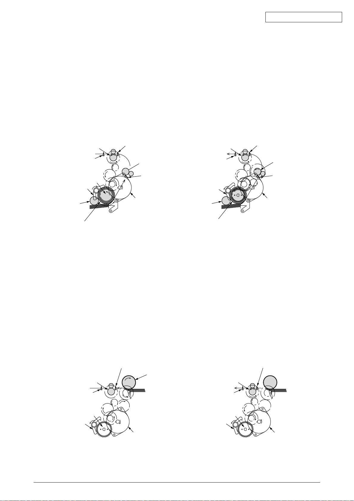
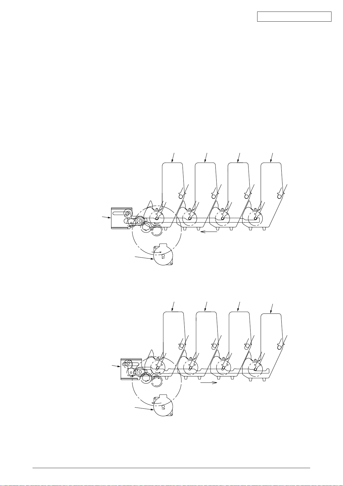
(1) Paper Feed from 1st Tray
1. As indicated in Figure 2-1, when the solenoid is ON, the registration motor rotates (CCW),
and transports the paper until IN1 sensor turns ON. (The hopping roller rotates when the
solenoid is ON.)
2. When IN1 sensor is ON, a constant number of sheets are transported against registration
roller L. (This corrects paper skewing.)
3. As indicated in Figure 2-2, the solenoid is turned OFF and paper is fed with registration roller
L. (The registration roller L feeds the paper when the solenoid is OFF.)
Registration Roller U
(Drive)
WR Sensor
Hopping Gear Assy
Solenoid Lever
(Solenoid ON)
Sub Roller
(Drive)
Hopping Roller
(Drive)
Paper
Figure 2-1 Figure 2-2
(2) Paper Feed from MPT
1. As indicated in Figure 2-3, when the solenoid is OFF, the registration motor rotates (CW)
and continues to transport paper until IN2 sensor turns ON. (The MPT hopping roller drives
the paper until the registration motor rotates in the CW direction.)
2. When IN2 sensor is turned ON, a constant number of sheets are transported against
registration roller U. (This corrects paper skewing.)
IN2 Sensor
Registration Roller L
(Stop)
IN1 Sensor
Registration Motor
(CCW)
Registration Roller U
(Drive)
WR Sensor
Solenoid Lever
(Solenoid OFF)
Sub Roller
(Stop)
Hopping Roller
(Stop)
IN2 Sensor
Registration Roller L
(Drive)
IN1 Sensor
Registration Motor
(CCW)
3. As indicated in Figure 2-4, the registration motor rotates (CCW), and transports the paper
with registration roller U. (The registration roller U feeds the paper when the registration
motor rotates in the CCW direction.)
IN2 Sensor
Registration Roller U
(Stop)
WR Sensor WR Sensor
Hopping Gear Assy
Solenoid Lever
(Solenoid OFF)
MPT Hopping Roller
Paper Paper
Hopping Gear Assy
Solenoid Lever
(Solenoid OFF)
Registration Motor
(CW)
Registration Roller U
(Drive)
IN2 Sensor
Registration Motor
(CCW)
Figure 2-3 Figure 2-4
42615101TH Rev.5 29 /
Oki Data CONFIDENTIAL
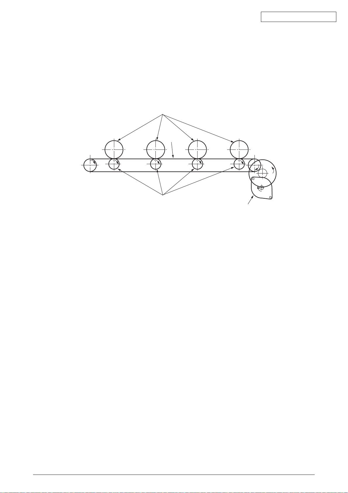
(3) Carrier Belt
1. The running of the carrier belt motor in the direction of the arrow drives the carrier belt. The
belt unit sits with one carrier roller immediately below each color’s drum, and the carrier belt
between them. By the application of a fixed voltage, the carrier belt and carrier roller feed
paper on the carrier belt into the fuser unit, transferring a toner image on each color’s drum.
Drum
Carrier belt
KYMC
Carrier (transfer) roller
Figure 2-5
Carrier (transfer) belt motor
42615101TH Rev.5 30 /
Oki Data CONFIDENTIAL
(4) ID Unit Up/Down Operations
1. The C-ID motor drives the ID unit up and down.
2. Figure 2-6 indicates ID unit operations during color printing. When the C-ID motor rotates
(CCW), the lift uplink slides to the left, and as indicated in Figure 2-6, each ID unit moves
DOWN. The printer is now ready for color printing.
3. Figure 2-7 indicates the ID unit operations during monochrome printing. When the C-ID
motor rotates (CW), the lift uplink slides to the right, and as indicated in Figure 2-7, all units
other than the K-ID moves UP. The printer is now ready for black-and-white printing.
ID Unit Operations During Color Printing
C-ID Unit down
C-ID Unit
M-ID Unit down
Y-ID Unit down
K-ID Unit down
Lift uplink
C-ID Motor
(CCW)
Figure 2-6
ID Unit Operations During Monochrome Printing
C-ID Unit
C-ID Unit lift up
M-ID Unit lift up
Y-ID Unit lift up
K-ID Unit down
M-ID Unit Y-ID Unit K-ID Unit
M-ID Unit Y-ID Unit
K-ID Unit
Lift uplink
C-ID Motor
(CW)
Figure 2-7
42615101TH Rev.5 31 /
Oki Data CONFIDENTIAL
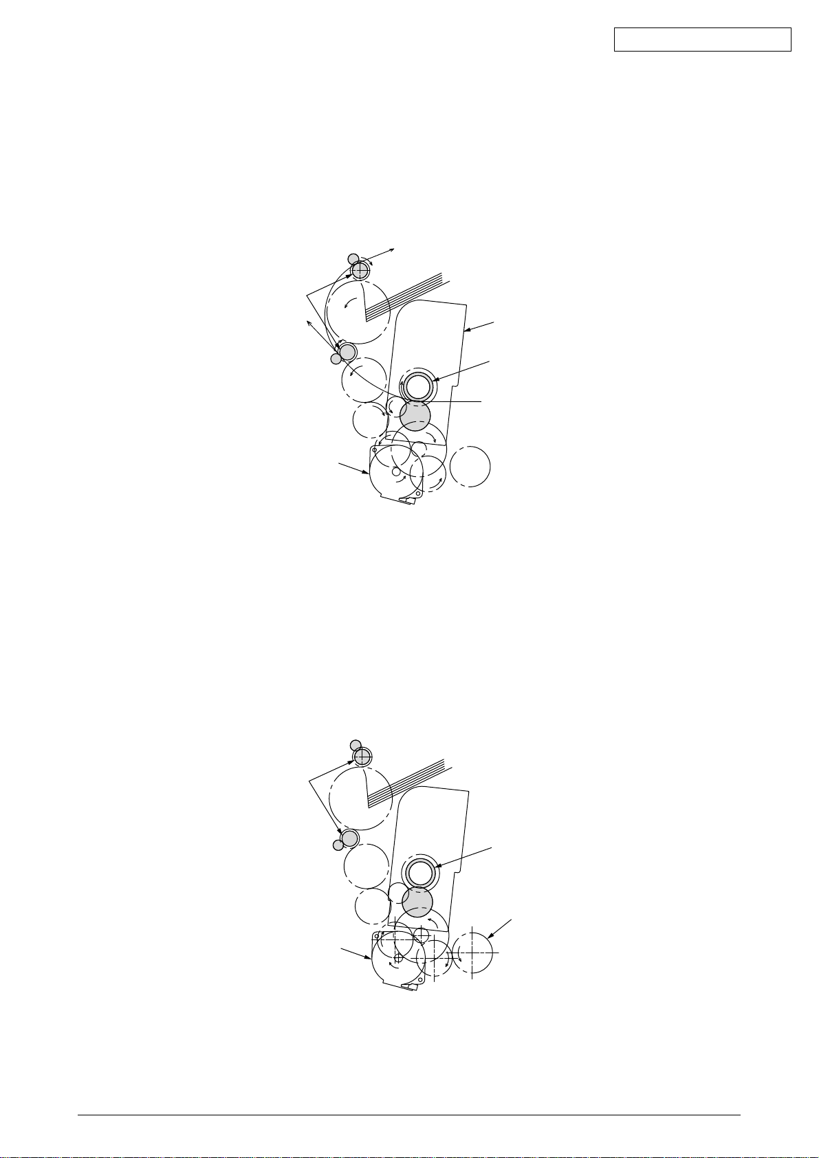
(5) Fuser Unit and Paper Expeller
1. As indicated in Figure 2-8, a single pulse motor drives the fuser unit and expeller roller. The
heat drum turns when the fuser motor turns (CCW). This drum transfers the toner image
on the paper by high temperature and pressure.
2. At the same time, the expeller roller expels the paper.
Eject Roller
(Drive)
Fuser Unit
Heat Roller
(Drive)
Fuser Motor
(CCW)
Figure 2-8
(6) Operations when the Color Drift Sensor and Density Sensor Cover is Opened
1. As indicated in Figure 2-9, when the fuser motor rotates (CW), the cover open gear rotates
and then opens the cover of the color drift sensor and density sensor.
2. When the fuser motor turns in the reverse direction (CCW), the cover open gear bite no
longer meshes, and then the color drift sensor and the density sensor cover closes.
Eject Roller
(Stop)
Heat Roller
(Stop)
Cover Open Gear
Fuser Motor
(CW)
Figure 2-9
42615101TH Rev.5 32 /
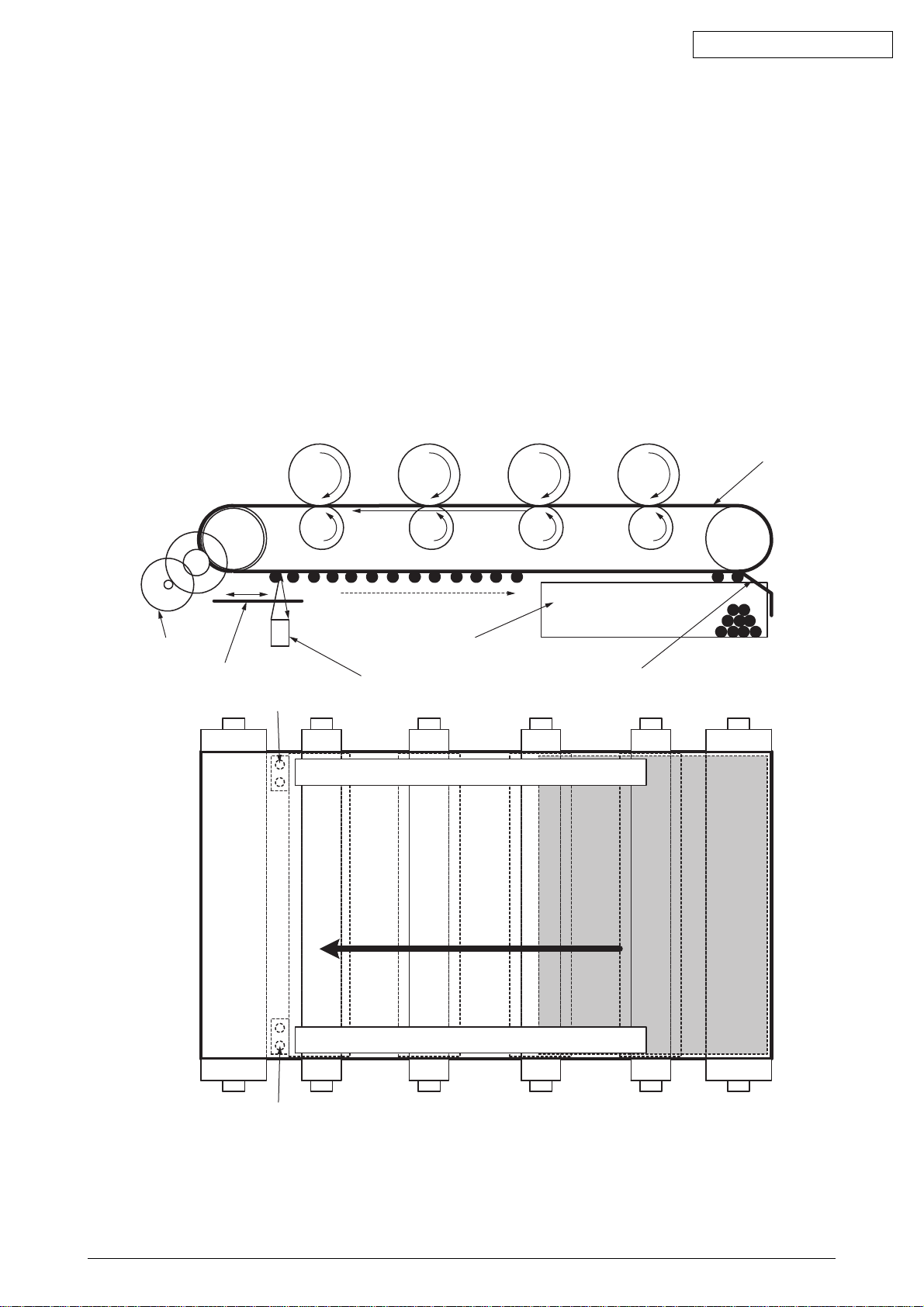
Outline of Color Misalignment Adjustment Method
Adjustment patterns printed on a transfer belt are read using sensors that are installed inside a
sensor shutter placed under a transfer belt unit, for adjusting color misalignments. The sensor
detects the patterns for adjusting color misalignments.
Auto-Start timing for Color registration
• In power-on
• When a cover is closed after the cover is open in a short time
• When printing 400 pages or more after the previous implementation
Toner amounts on the produced patterns, contamination of the sensor with toner, problems with
opening or closing of the sensor shutter, or other reasons, a color misalignment adjustment error
may occur. No control panel display of the error is provided. In such cases, adjustments on any
color misalignments (Section 5.4.2.6) are forced to be executed by the Self-diagnostic Mode and
displayed errors must be checked.
Oki Data CONFIDENTIAL
Transfer Belt
Belt Motor
Sensor Shutter
Color Registration Sensor
Belt Waste Toner Box
Color Registration Sensor
Right Color Misalignment Adjustment Pattern
Left Color Misalignment Adjustment Pattern
Belt Cleaning Blade
Color Registration Sensor
42615101TH Rev.5 33 /

Oki Data CONFIDENTIAL
How to check errors and Handling of the errors
Confirm with the color registration adjustment test of the self-diagnostic mode (Section 5.4.2.6)
Handling for each error
• CALIBRATION(L or R), DYNAMICRANGE(L or R)
Check 1 Check a connection state of a sensor cable (FFC) if the above description
appears.
Correct to a normal state if the connection state is wrong.
Check 2 Check that the surface of the sensor is clean without paper dust and toner.
Wipe it off if it is dirty.
Check 3 Check whether an opening-closing motion of the sensor shutter is normal with
MOTOR&CLUTCH TEST of the self-diagnostic mode.
Exchange the shutter unit when the opening-closing motion is not complete.
• BELT REFLX ERR
Check 4 Check a cleaning state of the toner left on a belt surface besides the above
Check 1, 2, and 3 if this message appears.
Take the belt unit out of the device and check that the belt surface is clearly
cleaned by rotating a drive gear in the back at the left side.
Exchange a belt unit when a toner of the belt surface is left and it is not clean even
if the drive gear rotates.
• (Y or M or C) LEFT, (Y or M or C) RIGHT, (Y or M or C) HORIZONTAL
Check 5 Check that a toner is not deficient due to NG color when the above message
appears.
Exchange a toner cartridge if needed.
42615101TH Rev.5 34 /
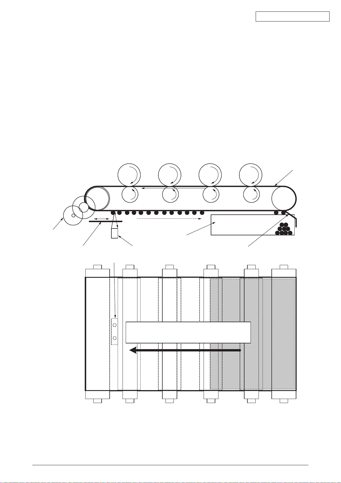
Outline of Print Density Adjustment Method
Adjustment patterns printed on a transfer belt are read using sensors that are installed inside a
sensor shutter placed under a transfer belt unit, for adjusting print density.
Auto-Start timing of Print Density Adjustment
• When environment is different considerably compared to the previous implementation in power-on
• At least 1 or more from 4 ID count values is almost new in power-on
• When ID count value is over 500 from the previous implementation
Toner amounts on produced patterns, contamination of optical sensors with toner, problems with
opening or closing of the sensor shutter, or other reasons, a print density adjustment error may
occur. No control panel display of the error is provided. In such cases, print density adjustments
(Section 5.4.2.7) on defective colors are forced to be executed by the Self-diagnostic Mode and
displayed errors must be checked.
Oki Data CONFIDENTIAL
Transfer Belt
Belt Motor
Sensor Shutter
Density Sensor
Density Sensor
Belt Waste Toner Box
Belt Cleaning Blade
Print Density Adjustment Pattern
42615101TH Rev.5 35 /

Oki Data CONFIDENTIAL
How to check errors and Handling of the errors
Confirm with the color registration adjustment test of the self-diagnostic mode (Section 5.4.2.7)
Handling for each error
• CALIBRATION ERR, DENS SENSOR ERR
Check 1 Check a connection state of the sensor cable when the above message
appears.
Correct to a normal state if the connection state is wrong.
Check 2 Check that the surface of the sensor is clean without paper dust and toner.
Wipe it off if it is dirty.
• EDENS SHUTTER ERR
Check 3 Check whether an opening-closing motion of the sensor shutter is normal with
MOTOR&CLUTCH TEST of the self-diagnostic mode.
• DENS ID ERR
Check 4 Check that there is no abnormal blushing on a drum surface by taking an ID unit
out.
Exchange a LED head (Defocusing) or exchange an ID unit.
Apply FUSE KEEP MODE of the maintenance menu when a new ID unit is used
as a test.
42615101TH Rev.5 36 /
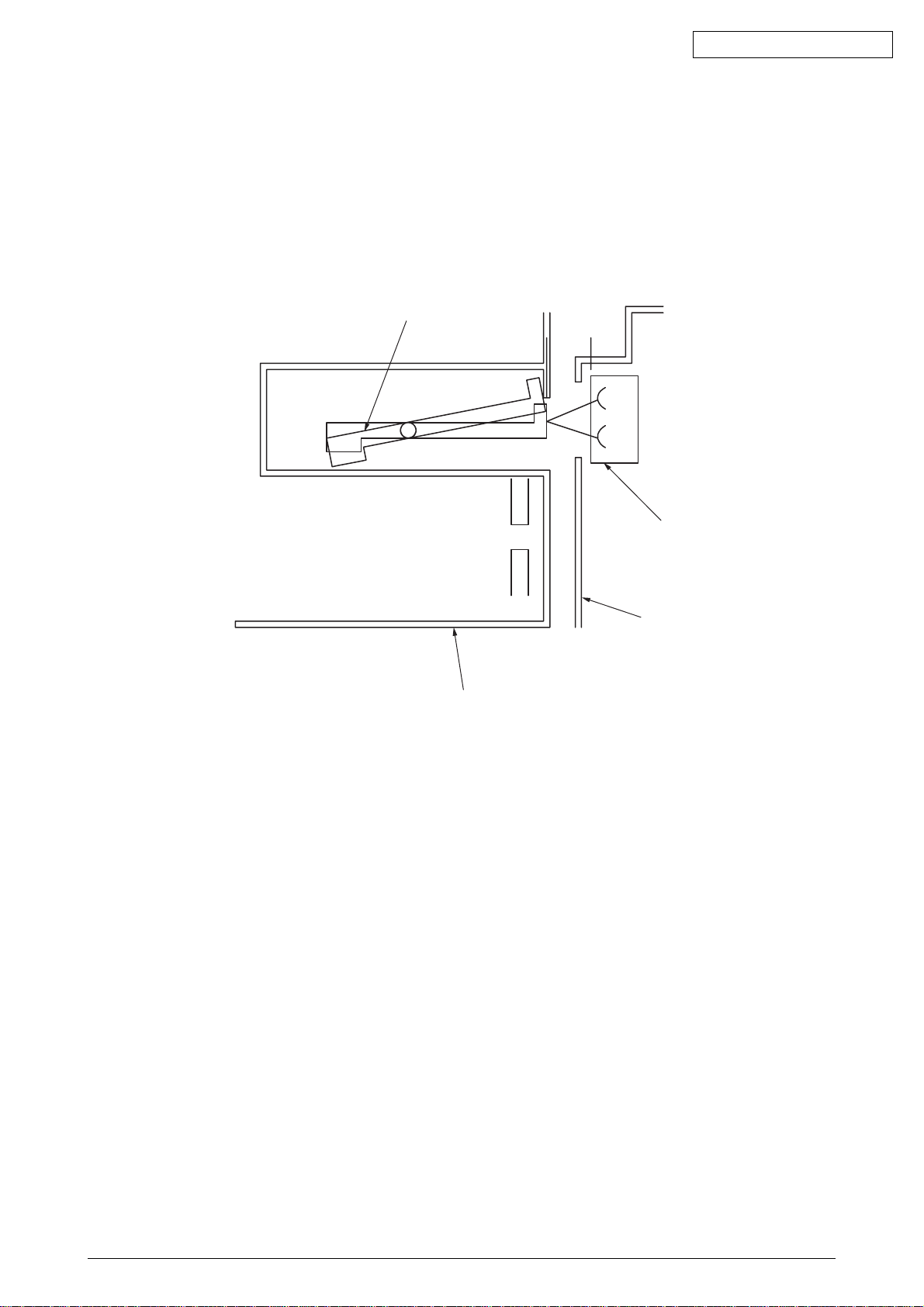
Principle of Detection by Toner Sensors
Movements of that sensor lever of a toner cartridge which is powered by an image drum (ID) motor
are read by a toner sensor for detecting that the cartridge is low on toner. The lever moves
concurrently with movement of a mixing bar placed in the cartridge. With the lever, or the sensor,
contaminated with toner etc., or the cartridge not facing the sensor properly due to improper ID unit
or toner cartridge installation, the sensor may not properly detect the cartridge being low on toner,
causing a toner sensor error.
Sensor Lever
Oki Data CONFIDENTIAL
Principle of the toner counter
After image data is developed to binary data which is printable, Dot counter counts the data as print
dots in LSI. Calculate the amount of the used toner with this count value to display a remaining
amount. Meanwhile, the toner LOW detection by the toner sensor has a function that Toner LOW
is detected when toner quantity in side of the toner cartridge is under a certain amount physically.
Principle of ID, Belt andFuser counter
ID counter : One third of the amount of drum rotation when three sheets of A4 paper is
printed continuously is regarded as one count.
Belt counter : One third of the amount of belt rotation when three sheets of A4 paper is printed
continuously is regarded as one count.
Fuser counter: On the basis of paper length of Leagal 13 inch, if it is 13 inch or less, it is
regarded as 1 count. If it is over 13 inch , the number of counters is determined
by multiples of Leagal 13 inch.(Round off to an integer value)
Toner Sensor
Side Plate
Toner Cartridge
42615101TH Rev.5 37 /

Oki Data CONFIDENTIAL
3. Printer Installation
3.1 Precautions and Prohibition
• Keep away from high temperatures and open flames.
• Please do not install in a place from which a chemical reaction is started (laboratory etc.).
• Do not install near inflammable solutions such as alcohol or thinner.
• Keep out of reach of children.
• Do not install on an unstable surface (the shaky stand, leaning place, etc.).
• Keep away from dust, humidity and direct sunlight.
• Keep away from the sea breeze and corrosive gases.
• Keep away from sources of vibration.
• Pull the power plug out of the socket and contact with a customer's service centre when the printer
is dropped or the cover is damaged.
There is a risk of getting an electric shock and/or causing fire leading to personal injury.
• Do not use a power code, a printer cable, or a ground wire other than those that are indicated in
User's Manual.
Doing so may case fire.
• Do not insert materials in a vent hole.
Doing so may cause an electric shock and/or fire leading to personal injury.
• Do not put a cup with liquids such as water on the printer.
Doing so may cause an electric shock and/or fire leading to personal injury.
• Do not touch the fuser and other parts when opened the cover.
Doing so may result in getting burns.
• Do not throw toner cartridges and image drum cartridges into fire. Doing so may cause dust
explosion leading to get burns.
• Do not use an inflammable spray near the printer. Failure to follow may cause fire since there is
an area heating up within the printer.
• Pull the power plug out of the socket and contact with a customer's service centre when the cover
is unusually hot, smoking, giving off questionable odour, or making a strange noise.
There is a risk of fire.
• Pull the power plug out of the socket and contact with a customer's service centre when a liquid
such as water enters in the internal parts of the printer.
There is a risk of fire.
• Pull the power plug out of the socket and remove foreign materials such as clips when they fall
inside the printer.
There is a risk of getting an electric shock and/or causing fire leading to personal injury.
• Do not operate and/or disassemble the printer other than that which is directed in User's Manual.
Doing so may cause an electric shock and/or fire leading to personal injury.
42615101TH Rev.5 38 /
 Loading...